

Page 1
Consultation with SebaKMT
1
User Manual
GSM Transmitter
Sebalog GT-3
Issue: 01 (01/2015) - EN
Article number: 83923
Mess- und Ortungstechnik
Measuring and Locating Technologies
Elektrizitätsnetze
Power Networks
Kommunikationsnetze
Communication Networks
Rohrleitungsnetze
Water Networks
Abwassernetze
Sewer Systems
Leitungsortung
Line Locating
Page 2

Consultation with SebaKMT
2
Page 3
Consultation with SebaKMT
3
Consultation with SebaKMT
The present system manual has been designed as an operating guide and for
reference. It is meant to answer your questions and solve your problems in as fast and
easy a way as possible. Please start with referring to this manual should any trouble
occur.
In doing so, make use of the table of contents and read the relevant paragraph with
great attention. Furthermore, check all terminals and connections of the instruments
involved.
Should any question remain unanswered or should you need the help of an authorized
service station, please contact:
Seba Dynatronic
Mess- und Ortungstechnik GmbH
Hagenuk KMT
Kabelmesstechnik GmbH
Dr.-Herbert-Iann-Str. 6
D - 96148 Baunach
Phone: +49 / 9544 / 68 – 0
Fax: +49 / 9544 / 22 73
Röderaue 41
D - 01471 Radeburg / Dresden
Phone: +49 / 35208 / 84 – 0
Fax: +49 / 35208 / 84 249
E-Mail: sales@sebakmt.com
http://www.sebakmt.com
SebaKMT
All rights reserved. No part of this handbook may be copied by photographic or other means unless SebaKMT
have before-hand declared their consent in writing. The content of this handbook is subject to change without
notice. SebaKMT cannot be made liable for technical or printing errors or shortcomings of this handbook.
SebaKMT also disclaims all responsibility for damage resulting directly or indirectly from the delivery, supply,
or use of this matter.
Page 4

Terms of Warranty
4
Terms of Warranty
SebaKMT accept responsibility for a claim under warranty brought forward by a
customer for a product sold by SebaKMT under the terms stated below.
SebaKMT warrant that at the time of delivery SebaKMT products are free from
manufacturing or material defects which might considerably reduce their value or
usability. This warranty does not apply to faults in the software supplied. During the
period of warranty, SebaKMT agree to repair faulty parts or replace them with new parts
or parts as new (with the same usability and life as new parts) according to their choice.
This warranty does not cover wear parts, lamps, fuses, batteries and accumulators.
SebaKMT reject all further claims under warranty, in particular those from consequential
damage. Each component and product replaced in accordance with this warranty
becomes the property of SebaKMT.
All warranty claims versus SebaKMT are hereby limited to a period of 12 months from
the date of delivery. Each component supplied by SebaKMT within the context of
warranty will also be covered by this warranty for the remaining period of time but for 90
days at least.
Each measure to remedy a claim under warranty shall exclusively be carried out by
SebaKMT or an authorized service station.
This warranty does not apply to any fault or damage caused by exposing a product to
conditions not in accordance with this specification, by storing, transporting, or using it
improperly, or having it serviced or installed by a workshop not authorized by SebaKMT.
All responsibility is disclaimed for damage due to wear, will of God, or connection to
foreign components.
For damage resulting from a violation of their duty to repair or re-supply items,
SebaKMT can be made liable only in case of severe negligence or intention. Any liability
for slight negligence is disclaimed.
Since some states do not allow the exclusion or limitation of an implied warranty or of
consequential damage, the limitations of liability described above perhaps may not
apply to you.
Page 5

Terms of Warranty
5
Contents
Consultation with SebaKMT ........................................................................................... 3
Terms of Warranty ........................................................................................................... 4
1 Safety Instructions ........................................................................................... 7
1.1 General Safety Instructions and Warnings ......................................................... 7
1.2 General Notes .................................................................................................... 7
2 Technical Description ...................................................................................... 9
2.1 Device construction ............................................................................................ 9
2.2 Function .............................................................................................................. 9
2.3 Communication ................................................................................................ 10
2.3.1 LOG RI / LOG RI+ wireless interfaces for the computer .................................. 10
2.3.2 Reader-3 as a wireless interface for the computer .......................................... 11
2.4 Power supply .................................................................................................... 12
2.4.1 Reading off the battery status .......................................................................... 12
2.4.2 Replacing the batteries ..................................................................................... 13
2.4.3 Resetting the internal logbook .......................................................................... 14
2.5 Specifications ................................................................................................... 15
2.6 Scope of delivery .............................................................................................. 15
3 Setting Up and Starting the Device .............................................................. 16
3.1 Access to SIM card and battery compartment ................................................. 16
3.2 Switching the GSM transmitter on/off ............................................................... 17
4 Preparatory Work in the Office ..................................................................... 19
4.1 Mobile communication, FTP server, email account etc. .................................. 19
4.2 Inserting the SIM card into the GSM transmitter .............................................. 19
4.3 Connecting the wireless interface to the PC/laptop ......................................... 20
4.4 Creating a logger group in the SebaDataView-3 software ............................... 20
4.5 Creating a GSM transmitter in the SebaDataView-3 software ......................... 21
4.6 Programming the GSM transmitter .................................................................. 22
4.6.1 Entering the GSM settings and transferring to the transmitter ......................... 22
4.6.2 Information on the GSM input window ............................................................. 23
4.7 Performing a GSM test ..................................................................................... 25
4.8 Exporting a logger group from the SebaDataView-3 software
and transferring it from the computer to Commander-3 ................................... 27
5 Working On-Site using a Laptop .................................................................. 29
5.1 Determining and storing the GPS position ....................................................... 29
5.2 Programming and linking devices .................................................................... 31
5.3 Installing devices at the place of use ............................................................... 33
5.4 Testing the mobile connection ......................................................................... 35
5.5 Linking the devices ........................................................................................... 35
Page 6

Terms of Warranty
6
5.6 Determining the GPS position using a smartphone/tablet ............................... 36
6 Working On-Site using the Commander-3 ................................................... 37
6.1 Determining and storing the GPS position ....................................................... 37
6.2 Programming the devices................................................................................. 39
6.3 Installing devices at the place of use ............................................................... 41
6.4 Testing the mobile connection ......................................................................... 43
6.5 Linking the devices ........................................................................................... 44
6.6 Determining the GPS position using a smartphone/tablet ............................... 45
6.7 Transferring logger groups from Commander-3 to the computer
and importing them into the SebaDataView-3 software ................................... 46
Page 7
Safety Instructions
7
1 Safety Instructions
1.1 General Safety Instructions and Warnings
• Do not drop the device / the system’s components or subject it / them to
strong impacts or mechanical shocks.
• The limits described under Technical Data may not be exceeded.
• The device / system must be in a technically perfect condition for
measurement.
1.2 General Notes
This manual contains basic instructions for the commissioning and operation of the
device / system. For this reason, it is important to ensure that the manual is always
available to the authorised and trained operator. He needs to read the manual
thoroughly. The manufacturer is not liable for damage to material or humans due to nonobservance of the instructions and safety advices provided by this manual.
Locally applying regulations have to be observed!
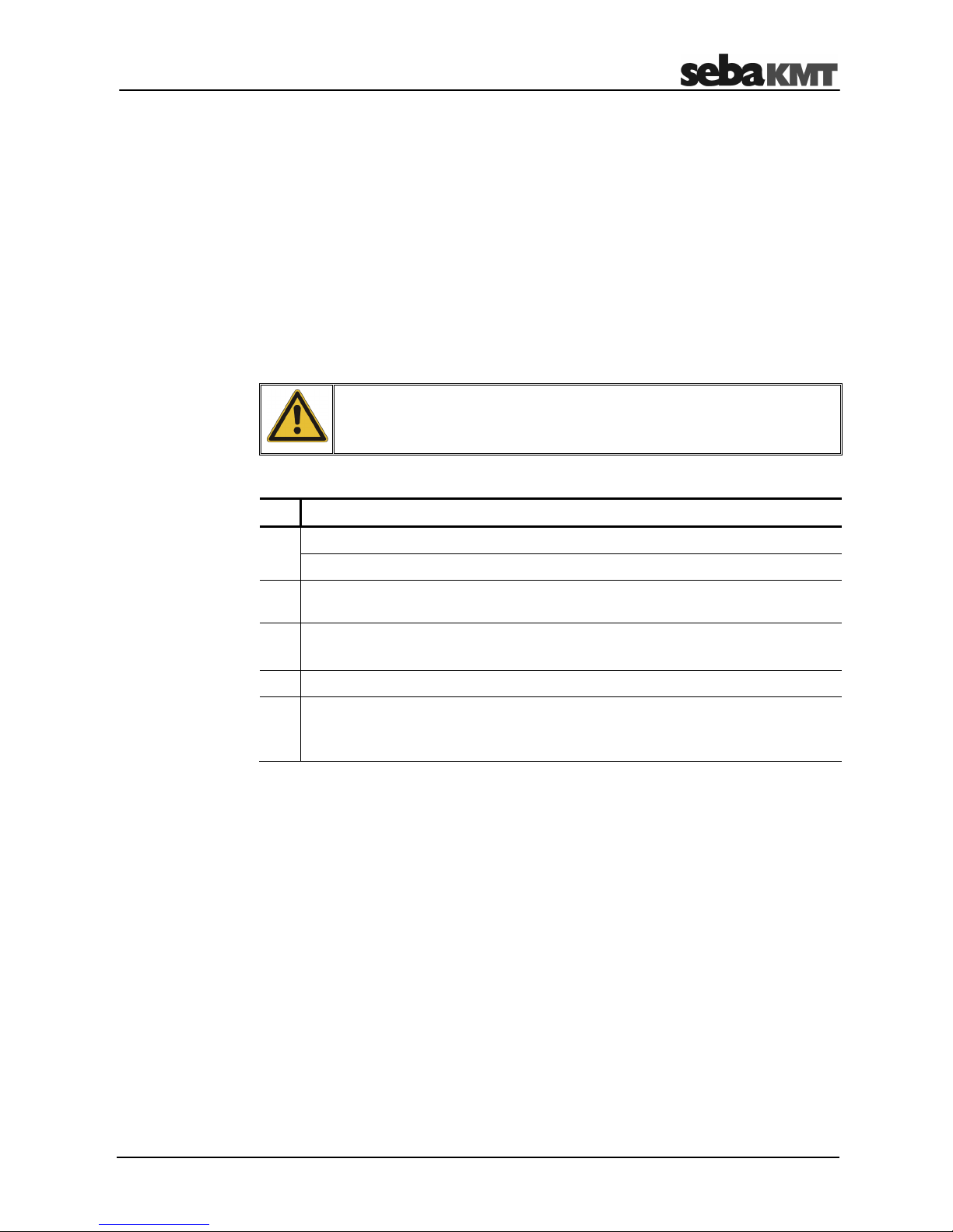
The following signal words and symbols are used in this manual and on the product
itself:
Signal word /
symbol
Description
CAUTION
Indicates a potential hazard which may result in moderate or minor
injury if not avoided.
NOTICE
Indicates a potential hazard which may result in material damage if not
avoided.
Serves to highlight warnings and safety instructions.
As a warning label on the product it is used to draw attention to
potential hazards which have to be avoided by reading the manual.
Serves to highlight important information and useful tips on the
operation of the device/system. Failure to observe may lead to
unusable measurement results.
Check the contents of the package for completeness and visible damage right after
receipt. In the case of visible damage, the device must under no circumstances be taken
into operation. If something is missing or damaged, please contact your local sales
representative.
It is important to observe the generally applicable regulations of the country in which the
device will be operated, as well as the current national accident prevention regulations
and internal company directives (work, operating and safety regulations).
Use genuine accessories to ensure system safety and reliable operation. The use of
other parts is not permitted and invalidates the warranty.
Repair and maintenance work has to be carried out by SebaKMT or authorised service
partners using original spare parts only. SebaKMT recommends having the system
tested and maintained at a SebaKMT service centre once a year.
SebaKMT also offers its customers on-site service. Please contact your service centre if
needed.
Safety precautions
Labelling of safety
instructions
Check contents
Working with products
from SebaKMT
Repair and
maintenance
Page 8

Safety Instructions
8
The lithium batteries of the device are dangerous goods. The transport of the batteries
itselves and of devices which contain such batteries is subject to regulations based on
the UN Model Regulations “Transport of Dangerous Goods” (ST/SG/AC.10-1).
Please inform yourself about the transportation requirements and follow them when
shipping the device.
This device is designed for industrial use. When used at home it could cause
interference to other equipment, such as the radio or television.
The interference level from the line complies with the limit curve B (living area), the
radiation level complies with the limit curve A (industrial area) according to EN 55011.
Given that living areas are sufficiently far away from the planned area of operation
(industrial area), equipment in living areas will not be impaired.
Special transportation
requirements
Electromagnetic
radiation
Page 9
Technical Description
9
2 Technical Description
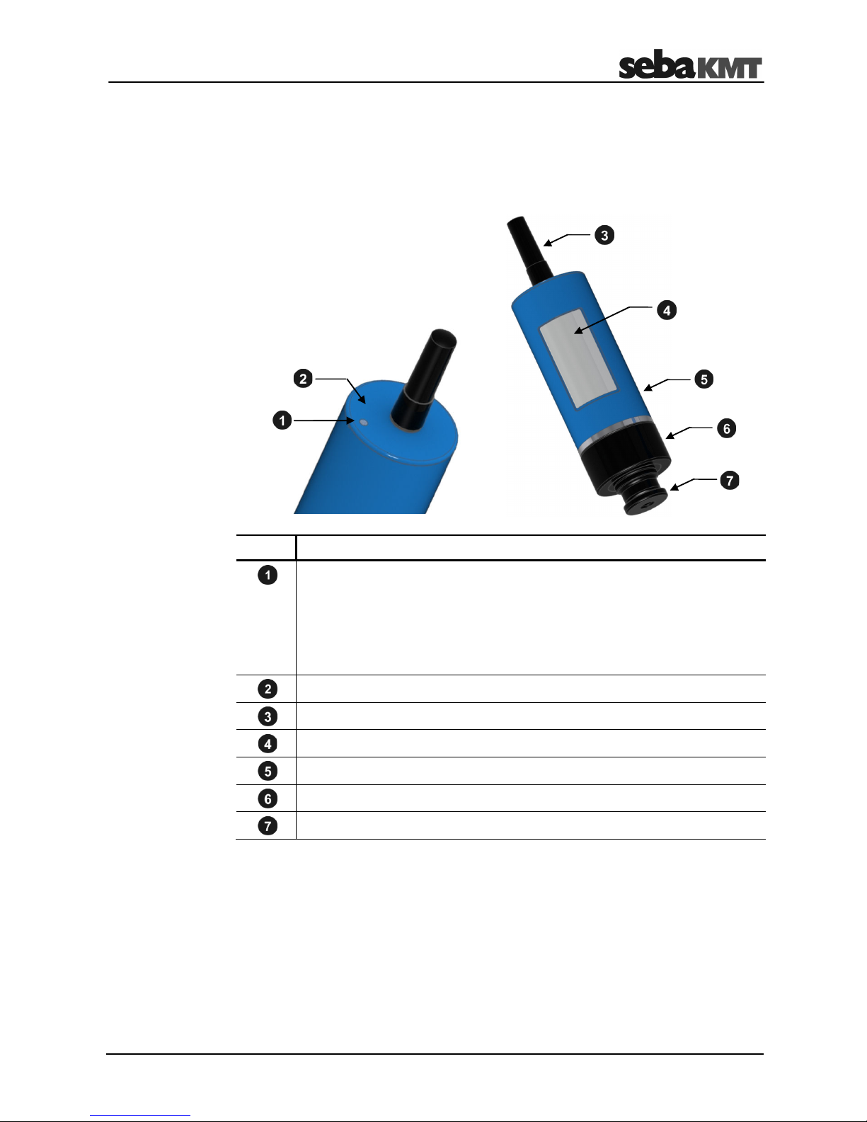
2.1 Device construction
The GSM transmitter has the following control elements and external features:
Element Description
Status LED
1 x red, 3 x green ... when switching on
Flashes blue ... device is switched on and ready for radio
communication
Permanently blue ... data transfer taking place
Yellow, then red ... when switching off
On/Off contact field (magnetic switch)
GSM antenna (interchangeable)
Type label with the identification number (ID) of the device
Housing
Locking ring (unscrewable)
Magnetic adapter (unscrewable)
2.2 Function
The "LOG GT-3" GSM transmitter is a compact, waterproof GSM module with its own
power supply.
The GSM transmitter acts as a mobile phone network interface for the following devices
in the Sebalog series:
• Log N-3 noise level logger
• Log P-3 pressure logger
External features
Page 10
Technical Description
10
The GSM transmitter makes it possible for the loggers with which it is connected to
perform the following functions:
• Regular uploading of measured data to an FTP server (once a day)
• Regular transmission of measured data via email/SMS
• Transmission of alarm messages via email/SMS if limit values are exceeded or
undercut
Up to three loggers can be connected to a GSM transmitter at the same time.
2.3 Communication
The GSM transmitter features an integrated GSM/GPRS modem and an integrated
wireless module for short-distance wireless transmission.
Short-distance wireless transmission:
• Communication between GSM transmitter and a logger
• Communication between GSM transmitter and a PC/laptop
(a wireless interface must be connected to the computer — please see the following
sections).
Mobile wireless communication:
• Transfer of logger-measured data from the GSM transmitter to the FTP server
• Transmission of notifications via email/SMS
2.3.1 LOG RI / LOG RI+ wireless interfaces for the computer
The "LOG RI" compact standard wireless interface is usually included in the scope of
delivery for devices in the Sebalog series.
The "LOG RI+" wireless interface is available from SebaKMT as accessory equipment.
In comparison with the LOG RI, the wireless module in this device is more powerful,
facilitating higher wireless ranges.
LOG RI
LOG RI+
Page 11
Technical Description
11
The LOG RI/LOG RI+ device connects easily to the computer via a USB port. After
connection, it activates itself automatically. The device is detected by the computer
automatically and is immediately ready to establish a wireless connection. No other
settings are required.
The LOG RI/LOG RI+ device features an LED for status indication:
• flashes 1x red, 1x green … when switching on
• lights up blue … during wireless operation
• lights up red … malfunction
It is recommended that the device is always operated using the latest firmware.
Information on updating device firmware can be found in the operating instructions for
the noise or pressure logger.
2.3.2 Reader-3 as a wireless interface for the computer
The "Reader-3" output device from SebaKMT can be used as a wireless interface.
Connect the device to the computer via the associated docking station and switch it on.
The device will then switch automatically to "USB mode". The device is detected by the
computer automatically and is immediately ready to establish a wireless connection. No
other settings are required. Additional information can be found in the user manual for
the Reader-3.
Operation
Status LED
Update
Page 12
Technical Description
12
2.4 Power supply
The GSM transmitter is powered by internal lithium batteries of the brand Energizer
Ultimate Lithium AA, but batteries from other manufacturers can also be used.
The batteries must satisfy the following technical criteria:
Parameters Value
Type Lithium battery
Size AA (ICE LR6)
Quantity 2
Rated voltage 1.5 V
Capacity Min. 3000 mAh
Continual discharge current Min. 3 A
2.4.1 Reading off the battery status
If you want to check the battery charge of a GSM transmitter, you can read the current
configuration for the respective device. The information on the status of the device will
contain one of the following statements:
• Battery full
• Battery OK
• Battery critical
You can request the current configuration of a GSM transmitter. The transmitter must be
switched on and within the wireless range of the output device.
Proceed as follows:
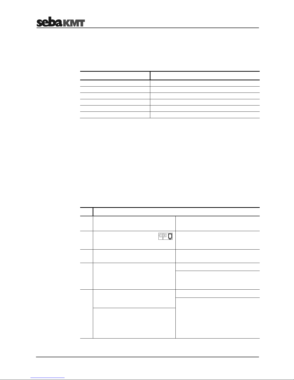
Step Description
Using the Commander-3
Using the computer
1
In Professional mode, open the
menu.
In the SDV-3 software, select the
respective GSM transmitter in the
directory tree.
2 Select the option Read device
configuration.
Click on Program in the menu bar.
4 Select the option Read GSM
transmitter config.
Click on Read in the input window.
Result: The current configuration of the
GSM transmitter is read out and
displayed.
5
Enter and confirm the identification
number (ID) of the GSM transmitter in
question.
Click on Status.
Result: A window opens showing
information on the current status of the
device.
This window also includes information
on the current battery charge status.
Result: The current configuration of the
GSM transmitter is read out and
displayed.
The "Status" line contains information
on the current battery state.
Requesting device
configuration
Page 13
Technical Description
13
2.4.2 Replacing the batteries
Empty batteries can be replaced by the user.
We recommend that batteries of the same brand and type as those supplied with the
device are used.
If you prefer to use batteries from a different manufacturer, you should ensure that these
batteries fulfill the necessary technical criteria (see page 12). Batteries with an
inadequate continuous discharge current are not suitable for use with the
GSM transmitter.
The technical specifications for a battery type are often not indicated on the packaging
or on the battery itself. The technical specifications can be requested from the
manufacturer.
NOTE
The device contains sensitive semi-conductor components.
Take care to avoid damaging the components. Never use force.
Proceed as follows:
Step Description
1
Open the device (see page 16).
Result: You can now access the SIM card slot and the battery compartment.
2
Carefully pull the battery tray out of the device until the batteries are freely
accessible.
3
Replace the batteries.
Make sure that you fit the new batteries with the correct polarity.
4
Carefully push the battery tray back into the device.
5
Close the device.
When doing so, make sure that the rubber seal of the sealing plug and the
sealing thread are free from dirt.
Whenever the batteries are replaced, the internal logbook for the respective
GSM transmitter must be reset (see following section). If this is not the case, this may
lead to incorrect information being provided when the battery charge status is requested
at a later point.
Procedure
Page 14
Technical Description
14
2.4.3 Resetting the internal logbook
This step can be carried out using the Commander-3 or the computer. The
GSM transmitter in question must be switched on and ready for wireless communication.
Proceed as follows:
Step Description
Using the Commander-3
Using the computer
1
In Professional mode, open the
menu.
In the SDV-3 software, select the
respective GSM transmitter in the
directory tree.
2 Select the option Read device
configuration.
Click on Program in the menu bar.
4 Select the option Read GSM
transmitter config.
Click on Read.
Result: The current configuration of the
GSM transmitter is read out and
displayed.
5
Enter and confirm the identification
number (ID) of the GSM transmitter in
question.
Click on Status.
Result: A window opens showing
information on the current status of the
device.
Result: The current configuration of the
GSM transmitter is read out and
displayed.
6
Go to the final configuration data page
using the Next button.
Click on Reset logbook.
(N.B.: If the button is not visible in the
status window, increase the window
size. Click on and drag the window
frame using the mouse whilst keeping
the left mouse button depressed).
7 Select the option Reset logbook.
Result: A connection to the GSM
transmitter is established.
All logbook entries for this device are
reset to "0".
Result: A connection to the
GSM transmitter is established.
All logbook entries for this device are
reset to "0".
Page 15

Technical Description
15
2.5 Specifications
The GSM transmitter has the following technical parameters:
Parameters Value
Display Status LED
Communication Short-distance radio transmission
868 MHz (in Europe)
913/916 MHz (depending on the country)
Mobile communication
GSM/GPRS modem, 850/900/1800/1900 MHz
Power supply 2 x 1.5 V lithium battery
Operating temperature -20 ... +60°C
Storage temperature -20 ... +70°C
Dimensions 124 x 44 mm Ø (without GSM antenna)
Weight 250 g
Degree of protection IP68
2.6 Scope of delivery
The standard scope of delivery includes the following components:
Accessory item Description Item no.
LOG GT-3 GSM transmitter 1003416
Magnetic adapter M8/M6 90008233
90-degree adapter for GSM antenna 90008232
Other accessory items are available in addition to the standard delivery scope:
Accessory item Description Item no.
GSM antenna with cable, 3 m 2004816
Magnetic angled adapter for transmitter 118303355
Magnetic adapter 820015167
Transport container for up to 15 transmitters 128311959
Eye bolt (short) 128302985
GPS receiver for laptop 820013945
LOG GPS-3 GPS receiver for Commander CDR-3 118303791
Standard accessories
Optional accessories
Page 16

Setting Up and Starting the Device
16
3 Setting Up and Starting the Device
3.1 Access to SIM card and battery compartment
The GSM transmitter must be opened in order to gain access to the SIM card slot or the
batteries.
NOTE
The device contains sensitive semi-conductor components.
Take care to avoid damaging the components. Never use force.
Proceed as follows:
Step Description
1
The device must be switched off (status LED permanently off).
2
The magnetic adapter must be screwed onto the device.
(When screwing on: tighten carefully! Do not over-tighten!)
3
Unscrew the black locking ring from the housing.
4
Carefully pull the sealing plug out of the housing.
Result: You can now access the SIM card slot and the battery compartment.
Opening the housing
Page 17

Setting Up and Starting the Device
17
To close the housing, first push the sealing plug carefully back into the housing and then
screw the locking ring back on.
Please note:
• The rubber seal of the sealing plug and all contact surfaces must be free from dirt.
• The thread of the locking ring and the housing must be free from dirt.
• Tighten the locking ring with care. Do not over-tighten!
3.2 Switching the GSM transmitter on/off
The GSM transmitter has an internal magnetic switch to turn it on and off.
Move the magnet provided over the on/off contact field . The status LED first
lights up red and then flashes green three times once the magnet has been removed.
Regular blue flashes then indicate that the device is switched on and ready to receive
data.
To switch off the device, hold the magnet against the on/off contact field for a few
seconds. The LED then lights up yellow. The magnet can be removed as soon as it
lights up red. The device then switches off and the LED goes out.
Closing the housing
Page 18

Setting Up and Starting the Device
18
Page 19

Preparatory Work in the Office
19
4 Preparatory Work in the Office
4.1 Mobile communication, FTP server, email account etc.
For data transfer via mobile communication, a corresponding contract must have been
concluded with a mobile service provider. You will need a SIM card which has been
approved for data transfer via GPRS.
You will need free storage space on an FTP server in order to upload the measured
data. For this purpose, you can either use your company's own server environment, or
you can conclude a user contract with a commercial provider on the Internet.
You can also rent storage space on an FTP server from SebaKMT. To do so, please
contact your SebaKMT sales partner.
Your computer will need read and write permissions for the relevant FTP server.
You will need an email account that sends alarm messages and measured data
overviews. You can either use your company's own mail server, or you can conclude a
usage contract with a commercial provider on the Internet.
Under certain conditions, it is also possible to access SebaKMT's own "Demo Account".
4.2 Inserting the SIM card into the GSM transmitter
A SIM card must be inserted in each GSM transmitter to be used for the purpose of
measurement. You will have received these from your mobile network operator when
you concluded the mobile phone contract.
Open the device (see page 16).
The SIM card slot is located inside the device on the bottom of the PCB. In order to
detach the tray for the SIM card from its fixture, push on the yellow spring mechanism to
the right of the card tray (see illustration), e.g. using a pen or similar item.
Pull out the tray and insert the SIM card. Then slide the tray back into the fixture as far
as the stop.
GSM/GPRS
FTP server
Emails
Inserting the SIM card
Page 20

Preparatory Work in the Office
20
As soon as the SIM card has been inserted, the device should be programmed with the
necessary GSM connection data so that a GSM connection test can be carried out.
Additional information on programming the GSM transmitter and on the GSM connection
test can be found in the following sections.
4.3 Connecting the wireless interface to the PC/laptop
In order to communicate with the GSM transmitter, you will need to connect a wireless
interface to the computer (see page 10).
4.4 Creating a logger group in the SebaDataView-3 software
A group must be created in the SebaDataView-3 software (or SDV-3 for short) on the
PC/laptop which contains all loggers to be used, or which could be used, for the
forthcoming measurement.
You can create a new group for this purpose, or you can add the loggers in question to
an existing group.
Please note:
Use of the GSM transmitter is possible in combination with
• Log P-3 pressure loggers
• Log N-3 noise loggers in the "Lift&Shift" group mode
Use of the GSM transmitter is not possible in combination with
• Log N-3 loggers in the "Patrol" group mode
• Log N-3 loggers in "Network" group mode
To create a new logger group, proceed as follows:
Select the required zone in the directory tree for the SDV-3, open the Directory register,
click on New in the Group segment and create a new group.
To add the required loggers to the group, proceed as follows:
Select this group in the directory tree, open the LogP or LogN3 register in the menu
bar, click on New in the Administration segment and then register the loggers one by
one.
Detailed information on creating and managing logger groups in the SDV-3 can be
found in the user manual for the logger in question.
Testing the GSM
connection
Restriction
Procedure
Page 21

Preparatory Work in the Office
21
4.5 Creating a GSM transmitter in the SebaDataView-3 software
All GSM transmitters that will be used for the forthcoming measurement must be set up
in the SebaDataView-3 software.
Proceed as follows:
Step Description
1
In the directory tree of the SDV-3 software, select the group to which the
GSM transmitter should be added. (The same group that contains the loggers
which will be used for the forthcoming measurement).
2 Click on New in the Administration segment in the menu bar.
(If necessary, first open the GSM transmitter tab).
Result: The window for registering new devices appears.
3
Register the GSM transmitter.
2 Methods
Manually Automatically
Deactivate the
Automatic detection
checkbox and enter the identification
number (ID) for the device.
Activate the
Automatic detection
checkbox and then switch on the GSM
transmitter.
Result: The identification number (ID)
for the device is recognized and
displayed.
Enter a comment for the device and confirm all details by pressing OK.
Result: The GSM transmitter is now registered and appears in the directory tree.
4
Register all additional GSM transmitters.
5 Click on Close to complete the procedure. (Pairing of the device is performed at a
later date at the place of use).
Page 22

Preparatory Work in the Office
22
4.6 Programming the GSM transmitter
4.6.1 Entering the GSM settings and transferring to the transmitter
The GSM transmitter must be programmed before the measurement is carried out.
During this process, all necessary GSM configuration data is assigned to the device.
The GSM transmitter must be switched on and within the wireless range of the
computer.
Proceed as follows:
Step Description
1
In the SDV-3 software, select the respective GSM transmitter in the directory tree.
2 Click on Program in the Communication segment in the menu bar.
(If necessary, first open the GSM transmitter tab).
Result: The window for entering the configuration data appears.
3
Enter all data necessary for the mobile connection (see following section).
4 In the Radio Settings segment, specify the week days and times that the
GSM transmitter should be accessible from outside via short-distance wireless
transmission (i.e. via computer or via Commander-3).
5 Click on Program.
Result: The GSM settings are transferred to the GSM transmitter.
A dialog box then appears, which asks whether you want to connect the GSM
transmitter to any loggers.
6 Click on No in the displayed dialog box.
Prerequisites
Procedure
Page 23

Preparatory Work in the Office
23
4.6.2 Information on the GSM input window
The figure shows the input screen for the GSM configuration data. This screen must be
completed with all parameters that are required for the correct functioning of the mobile
connection from/to the GSM transmitter. (The necessary data is specified in your mobile
phone contract, or can be requested from the mobile network operator).
This table explains the individual items in the configuration window.
Segment Parameters
SIM Card Settings
Enter the telephone number and the PIN code of the SIM card
used in the GSM transmitter.
Internet Settings
Enter the Internet access data for your mobile network operator
(server address, user name, password etc.).
By finding and selecting your mobile network operator in the
Templates drop-down list, the necessary data will be entered
automatically.
FTP Settings
Enter the access data for the FTP server to which the measured
data should be sent (server address, port, user name, password).
This data will have been provided when you concluded the FTP
usage agreement, or can be requested from the FTP server
operator.
If you have already stored the access data for your server in the
software system settings and wish to use this server, select the
Use own server checkbox. The data from the system settings is
then applied and appears in the input fields.
GSM parameters
Page 24

Preparatory Work in the Office
24
Segment Parameters
If you would like to use SebaKMT's demo server, select the
Seba Demo Mode checkbox. The access data is then entered
automatically.
(Please note that this server may only be used on a short-term
basis and for demonstration purposes only!)
Use the checkboxes to specify when the measured data upload
should take place:
Every selected GSM day
… Data is uploaded on a daily
basis (to be precise: on every
"GSM day").
Only in case of alarm
… Data is only uploaded if a
logger's leak threshold has been
exceeded during the last
measurement.
If you do not want any measured data uploads to take place, then
deactivate both checkboxes.
E-Mail Settings
Would you like to receive alarm messages via emails if a leak is
suspected or if a pressure surge occurs?
If so, then enter the access data for the sending email account
(domain, server address, port, user name, password). This data
will be provided by the operator of the email account or by your
system administrator.
If you have already stored the access data for the account in the
software system settings and wish to use this account, select the
Use own server checkbox. The data from the system settings is
then applied and appears in the input fields.
If you would like to use SebaKMT's demo account, select the
Seba Demo Mode checkbox. The access data is then entered
automatically.
(Please note that this account may only be used on a short-term
basis and for demonstration purposes only!)
E-Mail Destination
Would you like to receive alarm messages and measured-data
overviews via email?
If so, then enter up to two receiving addresses here.
Use the checkboxes to specify whether you wish to receive emails
only in the case of alarms or on a daily basis (to be precise: on
every "GSM day").
If you do not wish to receive any emails, then deselect both
checkboxes.
SMS Destination
Would you like to receive alarm messages and measured-data
overviews via SMS?
If so, then enter up to three recipient telephone numbers here.
Do not use any spaces or special characters.
Use the checkboxes to specify whether you wish to receive SMS
messages only in the case of alarms or on a daily basis (to be
precise: on every "GSM day").
If you do not want to receive any SMS messages, then deselect
both checkboxes.
Page 25

Preparatory Work in the Office
25
Segment Parameters
GSM Transmission
Specify the days on which you would like the GSM modem of the
GSM transmitter to be active (known as "GSM days").
It will only be possible to upload or send measured data or
messages on these days.
Segment Parameters
Wireless Settings
Specify the days and times per day that you would like the shortdistance wireless transmission module of the GSM transmitter to
be active (known as "Wireless days").
The GSM transmitter will only be able to communicate wirelessly
with other devices within these defined periods.
Please note: The "Wireless start time" set here is also set
automatically as the time at which the GSM transmitter requests
the previous night's measured data from the connected loggers
and forwards this data to the FTP server.
4.7 Performing a GSM test
In order to avoid on-site complications, an initial GSM test should be carried out in the
office on every GSM transmitter to be used for the measurement. This test checks
whether the device is able to establish a mobile wireless connection without error.
In order to carry out a GSM test using a computer, the following conditions must be met:
• A wireless interface must be connected to the computer (e.g. LOG RI).
• The GSM transmitter in question must be set up in the SDV-3 software.
• The GSM transmitter in question must be ready for GSM operation. (SIM card
inserted, GSM transmitter programmed)
• The GSM transmitter in question must be switched on and within the wireless range
of the computer.
In order to carry out a GSM test using a computer, proceed as follows:
Step Description
1
In the SDV-3 software, select the respective GSM transmitter in the directory tree.
2 Click on Check GSM in the Communication segment in the menu bar.
(If necessary, first open the GSM transmitter tab).
Result: A new window will open.
(continued on the next page)
"GSM days"
"Wireless days"
Prerequisites
Procedure
Page 26

Preparatory Work in the Office
26
Step Description
3 In the window, click on Check GSM.
Result: The GSM test is launched. The GSM transmitter uploads a test file to the
FTP server with the name "ftp-test.csv".
The GSM transmitter also sends a test email or test SMS to all specified
addressees with the following information:
• ID and comment on the GSM transmitter
• Information on the quality of the connection
• The wording "Test email" or "Test SMS"
The individual test steps are listed in the window on the screen. Steps that have
been successfully completed are marked as OK. Otherwise, an error message is
shown.
If the GSM test fails, check the following points again:
• Is a SIM card inserted in the GSM transmitter?
• Does the SIM card support data transfer?
(Check the mobile phone contract or contact the mobile network operator)
• Are GSM and data transfer active for the SIM card?
(Check with the mobile network operator)
• Do the settings match the SIM card in use?
• Do the settings match the GSM transmitter in use?
• Have the GSM settings been transferred to the GSM transmitter?
• Does the GSM transmitter have sufficient battery charge?
Causes of faults
Page 27

Preparatory Work in the Office
27
4.8 Exporting a logger group from the SebaDataView-3 software and
transferring it from the computer to Commander-3
If you are using Log N-3 noise loggers only, then all steps required on-site for
installation of the logger and the GSM transmitter can be carried out using the
Commander-3.
Transfer the logger group in question from the computer to the Commander-3.
The following prerequisites must be met:
• The Commander-3 must be operated in "Professional mode" rather than in
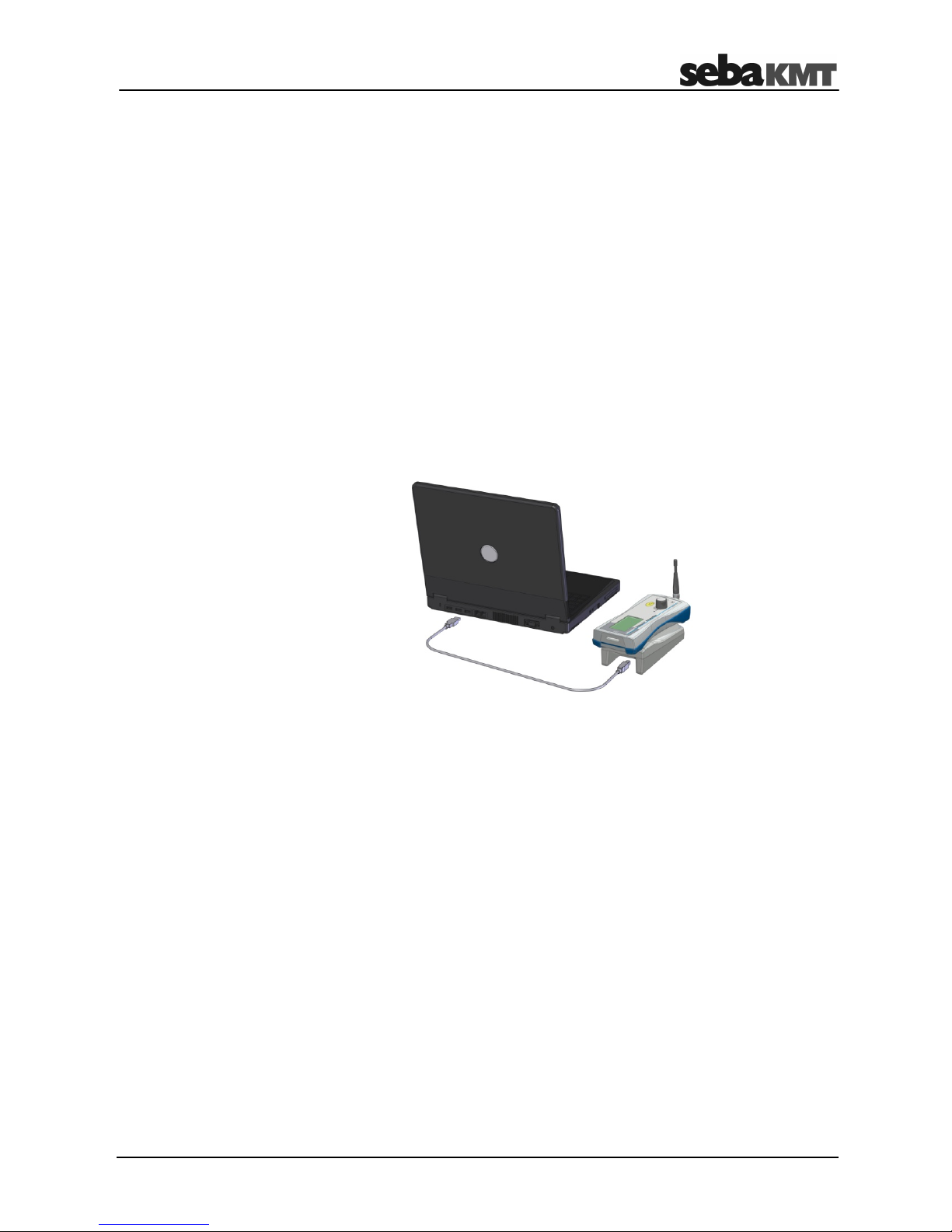
"Easy mode".
• You will need the connection cable VK77, which is supplied with Commander-3.
Proceed as follows:
Step Description
1
Establish a connection between the computer and the Commander-3.
(To do so, open the menu in the main menu bar of the Commander-3.
Select the option Connect to PC. Connect the devices using the connection
cable VK77. Select Connect in the Commander-3.)
2
In the SDV-3 software, select the respective group in the directory tree.
3 Click on Export in the Group segment in the menu bar.
(If necessary, first open the Directory tab.)
4 In the next window, click on Commander-3.
5
In the next window, navigate to the Commander-3 root directory and store the
group data there.
6
Stop the connection between the devices.
Would you prefer to work with the laptop on-site rather than with Commander-3?
If so, then the step described here is not relevant for you.
Prerequisites
Procedure
Page 28

Preparatory Work in the Office
28
Page 29

Working On-Site using a Laptop
29
5 Working On-Site using a Laptop
After completing the preparatory work in the office, all further steps are carried out at the
place of installation using a laptop.
The following prerequisites must be met:
• Laptop with SebaDataView-3 software
• A wireless interface must be connected to the laptop (e.g. LOG RI).
The individual work steps are explained in the following sections.
5.1 Determining and storing the GPS position
Determine the GPS position of the place of installation.
The GPS data for the places of installation is essential in order to perform online data
analysis using the "SebaKMT Cloud".
The GPS data is also useful for performing offline data analysis on the computer. All
devices can be displayed clearly in a chart, allowing them to be retrieved quickly and
securely.
2 Methods
Determining the GPS data
using a laptop
Determining the GPS data
using a smartphone/tablet
Prerequisite:
• External GPS receiver connected to
the laptop (available as an optional
accessory)
Prerequisites:
• GPS and Internet-enabled
smartphone or tablet
• On-site Internet access
• Access authorization
to "SebaKMT Cloud"
If you would like to determine the GPS
coordinates using a laptop, then please
do this as the first step at the place of
installation.
If you would like to determine the GPS
coordinates using your smartphone or
tablet (see page 36), then please do this
as the final step at the place of use
.
In order to determine position data using a laptop, you will need an external GPS
receiver from the range of SebaKMT accessories.
Simply connect the GPS receiver to the laptop via a USB port. Once connected, the
device switches on automatically and starts to search for available satellite signals
immediately.
Prerequisites
GPS receiver
for laptop
Page 30

Working On-Site using a Laptop
30
The GPS receiver features a status LED:
• LED flashes at
regular intervals
… Device is searching for GPS signals;
still not possible to establish position
• LED permanently lit … GPS signals are being received;
possible to establish position
• LED is not lit … Device is not connected
To determine the GPS position using a laptop, proceed as follows:
Step Description
1
Connect the GPS receiver to the laptop.
Result: The GPS receiver switches on and starts to search for available satellite
signals. It may take a few minutes to determine the first GPS position.
2
With your laptop and GPS receiver, move as close as possible to the place of
installation.
3
In the SDV-3 software, select the respective GSM transmitter in the directory tree.
4 Click on GPS in the Communication segment in the menu bar.
(If necessary, first open the GSM transmitter tab).
Result: A new window will open.
5 In the window, click on the GPS button.
Result: The current GPS position is determined and displayed.
(The laptop and GPS receiver should be kept as stationary as possible during this
process).
6 Click on the OK button.
Result: The procedure is complete. The data is stored in the SDV-3 database.
If you already know the GPS coordinates of the place of installation, then these can also
be entered or changed directly in the Latitude and Longitude input fields.
Determining the
GPS data
Entering/modifying
GPS data manually
Status LED
Page 31

Working On-Site using a Laptop
31
5.2 Programming and linking devices
Specify which loggers you wish to use on-site and for linking to the GSM transmitter.
During this step you can also set the measurement parameters for these loggers. You
can set a maximum of three loggers.
Proceed as follows:
Step Description
1
In the SDV-3 software, select the respective GSM transmitter in the directory tree.
2 Click on Program in the Communication segment in the menu bar.
(If necessary, first open the GSM transmitter tab).
Result: The window for entering the GSM settings appears.
The Device connection segment is at the bottom of the input screen.
3
Select the first logger to be linked to the GSM transmitter using the first of the
three drop-down menus.
The list includes all noise and pressure loggers for this group. If the required
logger is not in the list, this indicates that it has not yet been added to this group
(see page 7).
4
Set the measurement parameters for this logger. Follow steps 4a-4d.
4a
Click on the button to the right of the drop-down-menu.
Result: A new window will open showing the input screen for programming this
logger.
4b
Enter the measurement parameters for the forthcoming measurement.
(In order to save power, some input fields or checkboxes cannot be edited here.
Further information on the individual setting options can be found in the detailed
user manual for the logger in question).
4c Click on Save.
4d Click on OK in the success message.
Page 32

Working On-Site using a Laptop
32
Step Description
5
Would you like to select additional loggers for linking to the GSM transmitter?
If so, use the second and third drop-down menus and repeat steps 3 and 4 for
each additional logger.
6 In the GSM configuration window, click on Program at the bottom right-hand side,
and answer "Yes" to the security question.
Result: The configuration data will be sent to the GSM transmitter.
Once the data has been transferred successfully, a dialog box appears, asking
whether you want to link the GSM transmitter to the loggers.
Prerequisite: The loggers must be switched on and be in proximity to the
GSM transmitter.
6
Link devices now?
Click on Yes in the dialog box.
Do not link devices now?
Click on No in the dialog box.
In this case, the devices must
be linked (see page 35) on
another occasion.
Result: The GSM transmitter and the loggers will
be linked. At the same time, the measurement
settings are transferred to the loggers.
If one or more loggers are not connected, check
again whether these are switched on and within
range.
Radio interference may sometimes
occur if loggers are positioned too close
to the GSM transmitter.
Click on Link to logger in the menu bar to
repeat the process.
Page 33

Working On-Site using a Laptop
33
5.3 Installing devices at the place of use
Install the GSM transmitter together with the linked loggers at the place of use. The
devices must be within the same range.
Following installation, return the place of use to the exact state in which you found it
(close the shaft etc.). This will ensure that the subsequent GSM test is performed under
realistic conditions.
Ideally, all devices should be installed in the same shaft.
You can simply place the GSM transmitter in the shaft, or assemble the optional
magnetic base or magnetic angled adapter to secure the device in the shaft.
If the shaft is very narrow, you can fit the 90-degree antenna adapter, thereby bending
the GSM antenna. In some cases, better GSM reception can be an additional effect of
this measure.
If the shaft is very deep, you can replace the standard antenna with the optional
magnetic antenna and cable. Attach the antenna at the very top of the shaft, as close as
possible to the surface of the ground.
Installation information
Magnetic antenna
with cable
Standard antenna with
90-degree adapter
Magnetic angled
adapter
Page 34

Working On-Site using a Laptop
34
The following photos show real-life installation examples:
Log P-3 pressure logger with GSM transmitter in a German underground hydrant.
Log N-3 noise logger with GSM transmitter in a German gate shaft.
Log N-3 noise logger with magnetic angled adapter
and GSM transmitter with magnetic angled adapter and 90-degree antenna adapter
in a German gate shaft.
Installation examples
Page 35

Working On-Site using a Laptop
35
5.4 Testing the mobile connection
Once the logger and GSM transmitter have been installed, checks must be carried out
to verify that the mobile connection from the GSM transmitter has been set up without
error.
Perform a GSM test directly at the place of installation. When doing so, proceed exactly
as you did for the preparatory work in the office (see page 25).
If the GSM test fails, then it may be possible to improve the GSM reception using the
following measures:
• Change the position of the GSM transmitter and therefore the alignment of the
antenna in the shaft.
• Use the 90-degree angled adapter for the antenna.
• Replace the standard antenna with the optional magnetic antenna with cable.
Poor GSM test results may mean you will need to install the GSM transmitter in a
different position to the one originally planned. The determined GPS position may
therefore no longer be correct. In this case, you will need to work out the GPS position
of the new place of installation. You will then also need to repeat the "Programming and
linking devices" step (see page 31).
Has the GSM test been successful and is the GSM transmitter already linked to the
loggers? If so, then the devices are now ready for the measurement to be performed.
5.5 Linking the devices
The GSM transmitter must be "linked" to the loggers in use. As part of this same step,
the loggers are also programmed automatically (i.e. the temporarily stored measurement
settings are transmitted by the GSM transmitter to the individual loggers).
Proceed as follows:
Step Description
1
In the SDV-3 software, select the respective GSM transmitter in the directory tree.
2 Click on Link to logger in the Communication segment in the menu bar.
(If necessary, first open the GSM transmitter tab).
Result: The GSM transmitter and the loggers will be linked. This automatically
programs the loggers at the same time.
A message appears on the screen once the procedure has been completed
successfully.
Performing the
GSM test
Repositioning the
devices
Devices ready
for measurement
Has the GSM transmitter already been linked to the loggers (see page 31)? If so,
then the step described here is not relevant for you and should not be carried
out.
Procedure
Page 36

Working On-Site using a Laptop
36
5.6 Determining the GPS position using a smartphone/tablet
You can determine the GPS position of the place of installation using a smartphone or
tablet instead of the laptop. The data is immediately uploaded to the SebaKMT Cloud or
to your own server.
The following prerequisites must be met:
• GPS and Internet-enabled smartphone or tablet
• Internet access
• Access to the SebaKMT Cloud or to your own server
(have the URL, user name and password to hand!)
Proceed as follows:
Step Description
1
Move close to the installed GSM transmitter.
2
Activate the GPS function on your smartphone/tablet.
3
Open the SebaKMT Cloud web page and log in.
4
In the main menu, select the
GPS -> LOG DX, GT3 option under GPS assignment.
Result: A new menu level will open.
5
Select the checkbox below the GSM transmitter symbol.
6
Enter the identification number (ID) of the GSM transmitter for which you would
like to determine the GPS position.
7 Select Transmit.
Result: The GPS position of the smartphone/tablet is determined and stored in
the SebaKMT Cloud as the position of the GSM transmitters with associated ID.
A message appears on the screen once the procedure has been completed
successfully.
8 Click on the Menu button to return to the SebaKMT Cloud main menu. Here, you
can determine the GPS positions of additional GSM transmitters if needed.
To do so, simply repeat steps 4-6.
Select the logout option to log out of the SebaKMT Cloud.
Have you already established the GPS coordinates using a laptop?
If so, then the step described here is not relevant for you.
Prerequisites
Procedure
Page 37

Working On-Site using the Commander-3
37
6 Working On-Site using the Commander-3
After completing the preparatory work in the office, all further steps are carried out at
the place of use. You can use the Commander-3 for these steps rather than a laptop.
The following prerequisites must be met:
• Only Log N-3 noise loggers in "Lift&Shift" group mode are being used.
• No Log P-3 pressure loggers are being used.
• The Commander-3 must be operated in "Professional mode" rather than in
"Easy mode".
The individual work steps are explained in the following sections.
6.1 Determining and storing the GPS position
Determine the GPS position of the place of installation.
The GPS data for the places of installation is essential in order to perform online data
analysis using the "SebaKMT Cloud".
The GPS data is also useful for performing offline data analysis on the computer. All
devices can be displayed clearly in a chart and retrieved quickly and securely.
2 methods
Determining the GPS data
using the Commander-3
Determining the GPS data
using a smartphone/tablet
Prerequisite:
• External GPS receiver connected to
Commander-3
(available as an optional accessory)
Prerequisites:
• Internet and GPS-enabled
smartphone or tablet
• On-site Internet access
• Access authorization
to "SebaKMT Cloud"
If you would like to determine the GPS
coordinates using the Commander-3,
then please do this as the first step at the
place of use.
If you would like to determine the GPS
coordinates using your smartphone or
tablet (see page 45), then please do this
as the final step at the place of use
.
In order to determine position data using the Commander-3, you will need the
LOG GPS-3 external GPS receiver from the range of SebaKMT accessories.
Simply connect the GPS receiver to Commander-3 via the USB/GPS port. The receiver
switches on automatically when connected and the status LED lights up. The device
starts to search for available satellite signals immediately.
Prerequisites
GPS receiver
for Commander-3
Page 38

Working On-Site using the Commander-3
38
To determine the GPS position using the Commander-3, proceed as follows:
Step Description
1
Connect the GPS receiver to the Commander-3.
2
Move close to the place of installation.
3
Open the menu in the main menu bar of the Commander-3.
Result: The menu opens.
4 Select the Store GPS position option.
Result: A new menu level will open.
5
Select the required logger group using the drop-down menu at the top of the
screen.
6
Select the required GSM transmitter from the list.
7 Select the Store GPS pos button.
Result: A new view will open. The current GPS position is determined. (The
Commander-3 should be kept as stationary as possible during this process).
8 Wait until the position data is displayed reliably. Then select the Store button.
Result: This GPS data is now stored in the group data as the position of the
GSM transmitter.
Determining GPS data
Page 39

Working On-Site using the Commander-3
39
6.2 Programming the devices
Specify which loggers you wish to use on-site and for linking to the GSM transmitter.
During this step you can also set the measurement parameters for these loggers.
You can set a maximum of three loggers.
Proceed as follows:
Step Description
1
Switch on the respective logger.
2
Open the menu in the main menu bar of the Commander-3.
Result: The menu opens.
3 Select the Program GSM Transmitter option.
Result: A new menu level will open.
4
Select the required logger group from the drop-down menu at the top of the
screen.
5
Select the required GSM transmitter from the list.
6 Select the Progr. Transmitter button.
Result: A new menu level will open.
7
Select the first logger to be linked to the GSM transmitter using the first of the
three drop-down menus.
8
Click on the button to the right of the field, in order to specify the
measurement parameters for this logger.
Result: The input screen for the Log N-3 configuration now opens.
For power saving reasons, it is only possible to edit the parameters for
"Measurement period", "Values per measurement" and "Leak threshold value" at
this point.
Select the logger
from the list
Click on the symbol to
change the
measurement
parameters
Page 40

Working On-Site using the Commander-3
40
Step Description
9 Change the parameters and click Accept to confirm.
Result: The screen switches back to the previous menu level.
10
Would you like to select additional loggers for linking to the GSM transmitter?
If so, use the second and third drop-down menus.
Repeat steps 8 and 9 to specify the measurement parameters for each logger.
11 Select the Program button.
Result: The ID and comment for the GSM transmitter are displayed again.
12 Select the Program button.
Result: The configuration data for the loggers is now transferred to the
GSM transmitter where it is temporarily stored.
Page 41

Working On-Site using the Commander-3
41
6.3 Installing devices at the place of use
Install the GSM transmitter together with the loggers at the place of use. The devices
must be within the same range.
Following installation, return the place of use to the exact state in which you found it
(close the shaft etc.). This will ensure that the subsequent GSM test is performed under
realistic conditions.
Ideally, all devices should be installed in the same shaft.
You can simply place the GSM transmitter in the shaft, or assemble the optional
magnetic base or magnetic angled adapter to secure the device in the shaft.
If the shaft is very narrow, you can fit the 90-degree antenna adapter, thereby bending
the GSM antenna. In some cases, better GSM reception can be an additional effect of
this measure.
If the shaft is very deep, you can replace the standard antenna with the optional
magnetic antenna and cable. Attach the antenna at the very top of the shaft, as close as
possible to the surface of the ground.
Installation information
Magnetic antenna
with cable
Standard antenna with
90-degree adapter
Magnetic angled
adapter
Page 42

Working On-Site using the Commander-3
42
The following photos show real-life installation examples:
Log P-3 pressure logger and GSM transmitter in a German underground hydrant.
Log N-3 noise logger and GSM transmitter in a German gate shaft.
Log N-3 noise logger with magnetic angled adapter
and GSM transmitter with magnetic angled adapter and 90-degree antenna adapter
in a German gate shaft.
Installation examples
Page 43

Working On-Site using the Commander-3
43
6.4 Testing the mobile connection
Once the logger and GSM transmitter have been installed, checks must be carried out
to verify that the mobile connection from the GSM transmitter has been set up without
error. A GSM test must be carried out directly at the place of installation for this purpose.
Proceed as follows:
Step Description
1
In the Commander-3, open the menu for programming the GSM transmitter (see
page 39 steps 2-6).
2 Select the Check GSM button.
Result: In the subsequent view, the ID and comment for the specific
GSM transmitter are displayed again.
3 Click the Send command button.
Result: The GSM test is launched.
The GSM transmitter uploads a test file to the FTP server with the name
"ftp-test.csv".
The GSM transmitter also sends a test email or test SMS to all specified
addressees. This message contains the ID and comment for the GSM transmitter
as well as the wording "Test email" or "Test SMS".
The individual test steps are listed on the screen. Steps that have been
successfully completed are marked as OK. Otherwise, an error message is
shown.
If the GSM test fails, check once again that all GSM data has been entered correctly. It
may be possible to improve the transmitter's GSM reception by using a different antenna
or the 90-degree angled adapter for the antenna.
Page 44

Working On-Site using the Commander-3
44
Poor GSM test results may mean you will need to install the GSM transmitter in a
different position to the one originally planned. The determined GPS position may
therefore no longer be correct. In this case, you will need to work out the GPS position
of the new place of installation. You will then also need to repeat the "Programming
devices" step (see page 39).
6.5 Linking the devices
The GSM transmitter must be "linked" to the loggers in use. As part of this same step,
the loggers are also programmed automatically (i.e. the temporarily stored measurement
settings are transmitted by the GSM transmitter to the individual loggers).
Proceed as follows:
Step Description
1
In the Commander-3, open the menu for programming the GSM transmitter (see
page 39 steps 2-6).
2 Select the Link button.
Result: The ID and comment for the GSM transmitter are displayed again.
3 Click on the Send command button.
Result: The GSM transmitter and the loggers will be linked. This automatically
programs the loggers at the same time.
A message appears on the screen once the procedure has been completed
successfully.
Has the GSM test been successful and is the GSM transmitter already linked to the
loggers? If so, then the devices are now ready for the measurement to be performed.
Repositioning
the devices
Devices ready
for measurement
Page 45

Working On-Site using the Commander-3
45
6.6 Determining the GPS position using a smartphone/tablet
You can determine the GPS position of the place of installation using a smartphone or
tablet instead of the Commander-3. The data is immediately uploaded to the SebaKMT
Cloud or onto your own server.
The following prerequisites must be met:
• GPS and Internet-enabled smartphone or tablet
• Internet access
• Access to the SebaKMT Cloud or to your own server
(have the URL, user name and password to hand!)
Proceed as follows:
Step Description
1
Move close to the installed GSM transmitter.
2
Activate the GPS function on your smartphone/tablet.
3
Open the SebaKMT Cloud web page and log in.
4
In the main menu, select the
GPS -> LOG DX, GT3 option under GPS assignment.
Result: A new menu level will open.
5
Activate the checkbox below the GSM transmitter symbol.
6
Enter the identification number (ID) of the GSM transmitter for which you would
like to determine the GPS position.
7 Select Transmit.
Result: The GPS position of the smartphone/tablet is determined and stored in
the SebaKMT Cloud as the position of the GSM transmitters with associated ID.
A message appears on the screen once the procedure has been completed
successfully.
8 Click on the Menu button to return to the SebaKMT Cloud main menu. Here, you
can determine the GPS positions of additional GSM transmitters if needed. To do
so, simply repeat steps 4-6.
Select the Logout option to log out of the SebaKMT Cloud.
Have you already established the GPS coordinates using the Commander-3?
If so, then the step described here is not relevant for you.
Prerequisites
Procedure
Page 46

Working On-Site using the Commander-3
46
6.7 Transferring logger groups from Commander-3 to the computer and
importing them into the SebaDataView-3 software
As the final stage of preparatory work in the office, you exported the group data for the
logger group in question from the computer to Commander-3.
Once on-site work is complete, the data for this group will need to be transferred back
from Commander-3 to the computer and imported into the SebaDataView-3 software.
Proceed as follows:
Step Description
1
Establish a connection between the computer and the Commander-3.
(To do so, open the menu in the main menu bar of the Commander-3
(Professional mode!). Select the option Connect to PC. Connect the devices
using connection cable VK77. Select the Connect command in the
Commander-3).
2
Select the required logger group in the directory tree for the SDV-3 software.
3 Click on Import in the Group segment in the menu bar.
(If necessary, first open the Directory tab).
4 In the next window, click on Commander-3.
5
In the next window, navigate to the Commander-3 root directory, select the
required logger group and click on OK.
Result: The group data is transferred from Commander-3 and stored in the
SDV-3 database. A message appears on the screen once the procedure has
been completed successfully.
6
Stop the connection between the devices.
Procedure
 Loading...