


Consultation with SebaKMT
User Manual
Wireless Reading Device
PocketServer-3
Messund Ortungstechnik
Measuring and Locating Technologies
Elektrizitätsnetze
Power Networks
Kommunikationsnetze
Communication Networks
Rohrleitungsnetze
Water Networks
Abwassernetze
Sewer Systems
Leitungsortung
Line Locating
Issue: |
01 (10/2017) - EN |
Article number: |
** |
1

Consultation with SebaKMT
2

Consultation with SebaKMT
Consultation with SebaKMT
The present system manual has been designed as an operating guide and for reference. It is meant to answer your questions and solve your problems in as fast and easy a way as possible. Please start with referring to this manual should any trouble occur.
In doing so, make use of the table of contents and read the relevant paragraph with great attention. Furthermore, check all terminals and connections of the instruments involved.
Should any question remain unanswered or should you need the help of an authorized service station, please contact:
Seba Dynatronic |
Hagenuk KMT |
Messund Ortungstechnik GmbH |
Kabelmesstechnik GmbH |
|
|
Dr.-Herbert-Iann-Str. 6 |
Röderaue 41 |
D - 96148 Baunach |
D - 01471 Radeburg / Dresden |
Phone: +49 / 9544 / 68 – 0 |
Phone: +49 / 35208 / 84 – 0 |
Fax: +49 / 9544 / 22 73 |
Fax: +49 / 35208 / 84 249 |
|
|
E-Mail: sales@sebakmt.com
http://www.sebakmt.com
SebaKMT
All rights reserved. No part of this handbook may be copied by photographic or other means unless SebaKMT have before-hand declared their consent in writing. The content of this handbook is subject to change without notice. SebaKMT cannot be made liable for technical or printing errors or shortcomings of this handbook. SebaKMT also disclaims all responsibility for damage resulting directly or indirectly from the delivery, supply, or use of this matter.
3

Terms of Warranty
Terms of Warranty
SebaKMT accept responsibility for a claim under warranty brought forward by a customer for a product sold by SebaKMT under the terms stated below.
SebaKMT warrant that at the time of delivery SebaKMT products are free from manufacturing or material defects which might considerably reduce their value or usability. This warranty does not apply to faults in the software supplied. During the period of warranty, SebaKMT agree to repair faulty parts or replace them with new parts or parts as new (with the same usability and life as new parts) according to their choice.
This warranty does not cover wear parts, lamps, fuses, batteries and accumulators.
SebaKMT reject all further claims under warranty, in particular those from consequential damage. Each component and product replaced in accordance with this warranty becomes the property of SebaKMT.
All warranty claims versus SebaKMT are hereby limited to a period of 12 months from the date of delivery. Each component supplied by SebaKMT within the context of warranty will also be covered by this warranty for the remaining period of time but for 90 days at least.
Each measure to remedy a claim under warranty shall exclusively be carried out by SebaKMT or an authorized service station.
This warranty does not apply to any fault or damage caused by exposing a product to conditions not in accordance with this specification, by storing, transporting, or using it improperly, or having it serviced or installed by a workshop not authorized by SebaKMT. All responsibility is disclaimed for damage due to wear, will of God, or connection to foreign components.
For damage resulting from a violation of their duty to repair or re-supply items, SebaKMT can be made liable only in case of severe negligence or intention. Any liability for slight negligence is disclaimed.
Since some states do not allow the exclusion or limitation of an implied warranty or of consequential damage, the limitations of liability described above perhaps may not apply to you.
4

Terms of Warranty
Contents
Consultation with SebaKMT ........................................................................................... |
3 |
|
Terms of Warranty ........................................................................................................... |
4 |
|
1 |
Safety instructions ........................................................................................... |
9 |
1.1 |
General safety instructions and warnings .......................................................... |
9 |
1.2 |
General notes ..................................................................................................... |
9 |
1.3 |
FCC / ISED....................................................................................................... |
10 |
2 |
PS-3 - Basics................................................................................................... |
11 |
2.1 |
Technical data .................................................................................................. |
11 |
2.2 |
Buttons and LEDs ............................................................................................ |
11 |
2.3 |
Connections ..................................................................................................... |
12 |
2.4 |
Type plate......................................................................................................... |
12 |
2.5 |
Switching on/off ................................................................................................ |
12 |
2.6 |
User interface ................................................................................................... |
13 |
3 |
PS-3 – Commissioning .................................................................................. |
15 |
3.1 |
First connection ................................................................................................ |
15 |
3.2 |
Starts after the first connection ........................................................................ |
16 |
3.3 |
Selecting the language..................................................................................... |
16 |
3.4 |
Setting the time zone........................................................................................ |
16 |
3.5 |
Entering the license key ................................................................................... |
16 |
4 |
LOG N-3........................................................................................................... |
17 |
4.1 |
Managing loggers in PS-3 ................................................................................ |
17 |
4.1.1 |
Logger group .................................................................................................... |
17 |
4.1.2 |
Single loggers................................................................................................... |
18 |
4.2 |
Reading the measured data ............................................................................. |
20 |
4.2.1 |
Patrol ................................................................................................................ |
20 |
4.2.2 |
Reading out a Lift&Shift group ......................................................................... |
20 |
4.2.3 |
Reading out single loggers............................................................................... |
21 |
4.3 |
Displaying measurement data.......................................................................... |
21 |
4.3.1 |
Data of a Patrol group ...................................................................................... |
21 |
4.3.2 |
Data of a Lift&Shift group ................................................................................. |
24 |
4.3.3 |
Data of an individual logger.............................................................................. |
26 |
4.4 |
Reading out audio files..................................................................................... |
28 |
4.5 |
Reading out a configuration ............................................................................. |
28 |
4.6 |
Programming.................................................................................................... |
30 |
4.6.1 |
Logger groups .................................................................................................. |
30 |
4.6.2 |
Single loggers................................................................................................... |
31 |
4.7 |
Export data ....................................................................................................... |
32 |
4.8 |
Real-time measurements ................................................................................. |
34 |
|
|
|
|
5 |
|

|
|
Terms of Warranty |
4.9 |
GPS position .................................................................................................... |
35 |
4.10 |
Firmware update .............................................................................................. |
36 |
5 |
LOG P-3 / P-3 mini .......................................................................................... |
38 |
5.1 |
Managing loggers in PS-3 ................................................................................ |
38 |
5.2 |
Reading the measured data ............................................................................. |
39 |
5.3 |
Displaying measurement data.......................................................................... |
39 |
5.4 |
Reading out a configuration ............................................................................. |
41 |
5.5 |
Reading out pressure shocks........................................................................... |
42 |
5.6 |
Real-time measurements ................................................................................. |
42 |
5.7 |
GPS position .................................................................................................... |
44 |
5.8 |
Programming.................................................................................................... |
44 |
5.9 |
Export data ....................................................................................................... |
45 |
5.10 |
Firmware update .............................................................................................. |
46 |
6 |
LOG D-3 / SebaFlow / TDM 300 ..................................................................... |
48 |
6.1 |
Managing devices in PS-3................................................................................ |
48 |
6.2 |
Reading the measured data ............................................................................. |
49 |
6.3 |
Displaying measurement data.......................................................................... |
49 |
6.4 |
Reading out a configuration ............................................................................. |
51 |
6.5 |
Reading out pressure shocks........................................................................... |
52 |
6.6 |
Reading out night values.................................................................................. |
53 |
6.7 |
Reading out an event list.................................................................................. |
53 |
6.8 |
Real-time measurements ................................................................................. |
53 |
6.9 |
GPS position .................................................................................................... |
55 |
6.10 |
Programming.................................................................................................... |
55 |
6.11 |
Export data ....................................................................................................... |
59 |
6.12 |
Firmware update .............................................................................................. |
59 |
7 |
LOG DX / TDM 200.......................................................................................... |
61 |
7.1 |
Managing devices in PS-3................................................................................ |
61 |
7.2 |
Reading the measured data ............................................................................. |
62 |
7.3 |
Displaying measurement data.......................................................................... |
62 |
7.4 |
Reading out a configuration ............................................................................. |
64 |
7.5 |
Reading out pressure shocks........................................................................... |
65 |
7.6 |
Reading out night values.................................................................................. |
65 |
7.7 |
Reading out an event list.................................................................................. |
66 |
7.8 |
Real-time measurements ................................................................................. |
66 |
7.9 |
GPS position .................................................................................................... |
67 |
7.10 |
Programming.................................................................................................... |
68 |
7.11 |
Export data ....................................................................................................... |
71 |
6

Terms of Warranty
7.12 |
Firmware update .............................................................................................. |
72 |
|
8 |
PS-3 |
– Status & settings ................................................................................ |
74 |
8.1 |
Device info........................................................................................................ |
74 |
|
8.2 |
Settings............................................................................................................. |
75 |
|
8.2.1 |
Language ......................................................................................................... |
75 |
|
8.2.2 |
Region and time zone ...................................................................................... |
75 |
|
8.2.3 |
Transfer rate..................................................................................................... |
75 |
|
8.2.4 |
Real-time display.............................................................................................. |
75 |
|
8.3 |
All other options................................................................................................ |
76 |
|
8.4 |
GPL information ............................................................................................... |
76 |
|
9 |
PS-3 |
– Exporting all data ............................................................................... |
77 |
10 |
PS-3 |
– Firmware update................................................................................. |
78 |
7

Terms of Warranty
8

Safety instructions
1 |
Safety instructions |
1.1General safety instructions and warnings
Do not drop the device / the system’s components or subject it / them to strong impacts or mechanical shocks.
The limits described under Technical Data may not be exceeded.
The device / system must be in a technically perfect condition for measurement.
1.2General notes
Safety precautions This manual contains basic instructions for the commissioning and operation of the device / system. For this reason, it is important to ensure that the manual is always available to the authorised and trained operator. He needs to read the manual thoroughly. The manufacturer is not liable for damage to material or humans due to nonobservance of the instructions and safety advices provided by this manual.
Locally applying regulations have to be observed!
Labelling of safety The following signal words and symbols are used in this manual and on the product instructions itself:
Signal word / Description symbol
CAUTION Indicates a potential hazard which may result in moderate or minor injury if not avoided.
NOTICE Indicates a potential hazard which may result in material damage if not avoided.
Serves to highlight warnings and safety instructions.
As a warning label on the product it is used to draw attention to potential hazards which have to be avoided by reading the manual.
Serves to highlight important information and useful tips on the operation of the device/system. Failure to observe may lead to unusable measurement results.
Check contents Check the contents of the package for completeness and visible damage right after receipt. In the case of visible damage, the device must under no circumstances be taken into operation. If something is missing or damaged, please contact your local sales representative.
Working with products It is important to observe the generally applicable regulations of the country in which the from SebaKMT device will be operated, as well as the current national accident prevention regulations
and internal company directives (work, operating and safety regulations).
Use genuine accessories to ensure system safety and reliable operation. The use of other parts is not permitted and invalidates the warranty.
Repair and Repair and maintenance work has to be carried out by SebaKMT or authorised service maintenance partners using original spare parts only. SebaKMT recommends having the system
tested and maintained at a SebaKMT service centre once a year.
SebaKMT also offers its customers on-site service. Please contact your service centre if needed.
9

Safety instructions
Special transportation The lithium batteries of the device are dangerous goods. The transport of the batteries requirements itselves and of devices which contain such batteries is subject to regulations based on
the UN Model Regulations “Transport of Dangerous Goods” (ST/SG/AC.10-1).
Please inform yourself about the transportation requirements and follow them when shipping the device.
Electromagnetic This device is designed for industrial use. When used at home it could cause radiation interference to other equipment, such as the radio or television.
The interference level from the line complies with the limit curve B (living area), the radiation level complies with the limit curve A (industrial area) according to EN 55011. Given that living areas are sufficiently far away from the planned area of operation (industrial area), equipment in living areas will not be impaired.
1.3FCC / ISED
For FCC:
This device complies with Part 15 of the FCC Rules. Operation is subject to the following two conditions:
(1)this device may not cause harmful interference, and
(2)this device must accept any interference received, including interference that may cause undesired operation.
No changes shall be made to the equipment without the manufacturer’s permission as this may void the user’s authority to operate the equipment.
This device complies with the safety requirements for RF exposure in accordance with FCC Part 15.1093 for portable use conditions.
For ISED:
This device contains licence-exempt transmitter(s)/receiver(s) that comply with
Innovation, Science and Economic Development Canada’s licence-exempt RSS(s).
Operation is subject to the following two conditions:
(1)This device may not cause interference.
(2)This device must accept any interference, including interference that may cause undesired operation of the device.
This device complies with the safety requirements for RF exposure in accordance with RSS-102 Issue 5 for portable use conditions.
The highest reported SAR value is 0.15W/Kg.
Pour ISED:
Le présent appareil est conforme aux CNR d'Industrie Canada applicables aux appareils radio exempts de licence. L'exploitation est autorisée aux deux conditions suivantes :
(1)l'appareil ne doit pas produire de brouillage.
(2)l'utilisateur de l'appareil doit accepter tout brouillage radioélectrique subi, même si le brouillage est susceptible d'en compromettre le fonctionnement.
Cet appareil est conforme aux exigences de sécurité concernant l’exposition aux RF selon la norme RSS-102, 5ème édition, pour des conditions d’utilisation portable.
La valeur maximale de SAR rapportée est de 0.15W/Kg.
10
PS-3 - Basics
2 PS-3 - Basics
2.1Technical data
The PocketServer is distinguished by the following technical parameters:
Parameter |
Value |
|
|
Communication |
Short range radio |
|
868 MHz (in Europe) |
|
913.02 MHz (in the US) |
|
913 / 916 MHz (depending on the country) |
|
WIFI Access-Point |
|
2.4 GHz |
|
|
Storage |
Internal 8 GB Micro SD card |
|
(approx. 6.5 GB free for measured and device data) |
|
|
Battery |
Internal rechargeable battery pack (Li-Ion) |
|
3.6 V, 4700 mAh |
|
|
Charger |
5V, 2A |
|
|
Operating time |
approx. 10 h |
|
|
Charging time |
approx. 5 h |
|
|
Connectors |
Micro USB connector for charger |
|
Mini USB connector for radio interface LOG RI+ |
|
USB connector for storage device |
|
|
Operating temperature |
-20 … +60°C |
|
|
Storage temperature |
-25 … +70°C |
|
|
Dimensions |
150 x 92 x 29 mm |
|
|
Weight |
280 g |
|
|
2.2Buttons and LEDs
 On/Off button
 Status LEDs
Displays in operation the battery status of the PocketServer.
 Charging indicator light
Lights up during battery charging. Turns off when the battery is full.
 Wireless LED
Lights when there is radio contact between the PocketServer and a device.
11
PS-3 - Basics
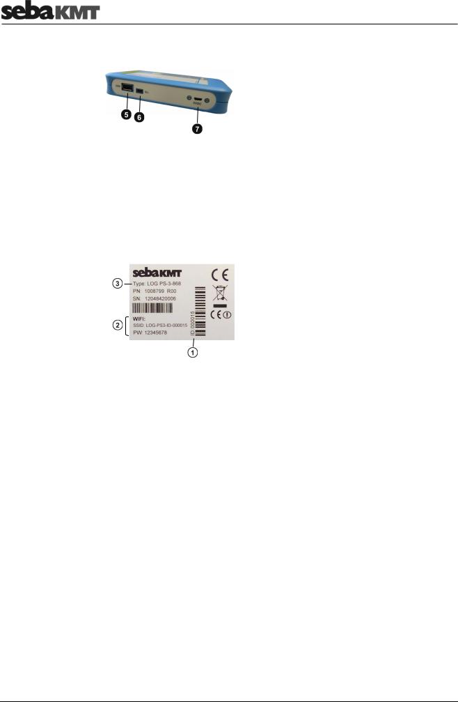
2.3Connections
 USB port
Connects to a USB data storage device.
 Connection for the radio module LOG RI+
 Connection for charger
2.4Type plate
 Identification number (ID)
 Access to PocketServer WLAN
SSID: Name of WLAN PW: Password for WLAN
 Type designation
The last three digits correspond to the radio frequency of the device (here: 868 MHz).
2.5Switching on/off
Switching on To switch on the PocketServer, briefly press the I/O button on the device. The blue and one green LED light up.
The device takes some time to start up the internal processor. During this time, the blue LED flashes at short intervals.
Do not interrupt the power-on procedure!
At the end of the process, the blue LED flashes three times at long intervals and then goes out.
The device is now ready for operation. The PocketServer WLAN network is established and available. The green LED bar indicates the battery status of the PocketServer.
12
PS-3 - Basics
Switching off There are two ways to turn off the PocketServer.
Option 1: in the user interface
► Tap these keys one after the other:
Option 2: with the I/O button on the PocketServer
►Press the I/O button on the unit for about two seconds. Release the button as soon as the green LEDs go out.
The device takes some time to shut down the internal processor. During this time, a single green LED is on.
Do not interrupt the power-off procedure!
Once the green LED goes out, the device is switched off.
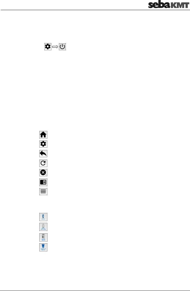
2.6User interface
Quick selection buttons Four quick selection buttons can be found in the corners of the user interface. Which of the following buttons are currently available depends on the active menu.
This button opens the start screen of the PocketServer.
This button opens the configurations of the PocketServer.
This button returns you to the previous screen.
This button refreshes the screen.
This button cancels the current operation.
This button opens the PocketServer help.
This button opens a list of frequently used options. The options that are available in the list depend on the active menu.
The start screen In the start screen, select the device type with the large buttons.
Tap this button, when you want to communicate with LOG N-3 noise-loggers.
Tap this button when you want to communicate with LOG P-3 or LOG P-3 mini pressure-loggers.
Tap this button when you want to communicate with LOG DX data-loggers or with TDM 200 devices.
Tap this button when you want to communicate with LOG D-3 data-loggers with SebaFlow devices or TDM 300 devices
13
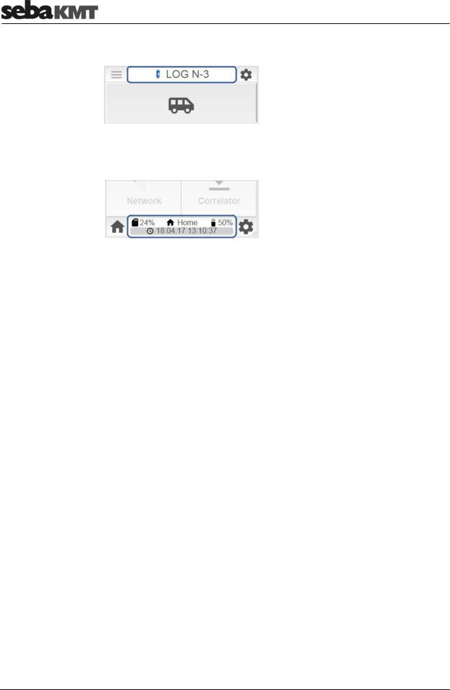
PS-3 - Basics
Header/footer In the segment at the top of the screen, the currently open device type is shown.
In the segment on the bottom of the screen, current information on the status of the PocketServer is shown.
Upper line (from left to right):
Utilization of internal data storage; Name of the displayed menu or ID of the contacted device; Battery level;
Bottom line:
Date and time of the PocketServer; Once a data transfer takes place, a bar here shows the progress of the procedure.
14
PS-3 – Commissioning
3 PS-3 – Commissioning
Here you can find information about what needs to be done after switching on the PocketServer in order to make the device ready for operation.
3.1First connection
First step: Create a WLAN connection
Second step: Open URL
Third step: Create quick-start button
To connect the PocketServer to a smartphone or other mobile device for the first time, follow these steps:
► Switch on PocketServer
►On your mobile device: activate WLAN
►Open list of available WLAN networks
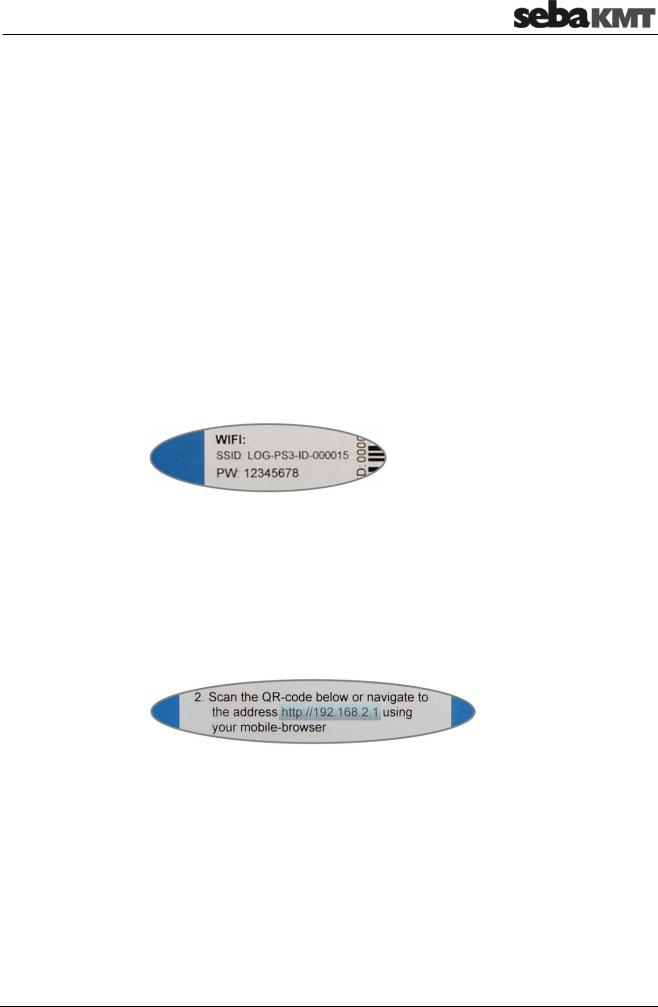
►The PocketServer network is named LOG-PS3-ID-******
If this network is not in the list, it must be added. To this end, look for and open the option ‘Add network’ (or a similarly named setting) in the WLAN settings. Enter the ‘SSID’ of the PocketServer as network name and confirm. The SSID can be found on the type plate.
►Select the PocketServer network in the list.
►Login using the password 12345678. You can also find the password (PW) on the type plate.
The mobile device is now logged into the WLAN network of the PocketServer. In the status bar of the mobile device, the WiFi symbol  should now be visible.
►Open Internet browser and open the following URL: http://192.168.2.1
This URL can also be found on the type plate. Alternatively, you can scan the QR code on the type plate.
The user interface of the PocketServer is now displayed on the mobile device.
You can create a quick-start button for the PocketServer on the start screen of your mobile device. This makes the PocketServer user interface easier to open next time.
►In the browser menu bar look for and open the option ‘Add to start screen’ (or a similarly named setting).
15
PS-3 – Commissioning
3.2Starts after the first connection
After the first connection, access to the PocketServer WLAN is saved in your mobile device. The devices detect each other and automatically connect from then on.
►Switch the PocketServer on.
►Wait until the WiFi symbol  is shown in the status bar of the mobile device.
►Tap on the LOG PS-3 button in the start screen.
 NOTE
NOTE
As long as the mobile device is logged into the PocketServer's WLAN network, there is no reception for other mobile data, meaning the device does not receive and send any e-mails, messages or other data via the mobile network.
3.3Selecting the language
You can change the operating language.
►Tap these buttons one after the other:
►Select your language and confirm with OK.
3.4Setting the time zone
For correct functioning of the PocketServer, it is important that the device knows the region and the time zone in which it is located.
►Tap the button 
 .
.
►Tap Settings.
►Tap Region.
►Select your region and time zone and confirm with OK.
3.5Entering the license key
In the basic version, the PocketServer user interface provides functions for reading measured data. Additional functions (such as programming devices, correlation of data, etc.) can be activated after purchasing a license. The user receives a number code, the license key.
►In the start screen, tap the button 
 .
.
►In the context menu, tap on enter license-code. A dialogue window opens.
►Enter the license key and confirm with OK.
The new functions are now enabled. If they are not available in the user interface, refresh the screen with the button 
 .
.
16
LOG N-3
4 LOG N-3
Here you can find information about all functions that are available for working with LOG N-3 sound loggers.
4.1Managing loggers in PS-3
4.1.1Logger group
To create, edit or delete logger groups in the PocketServer, proceed as follows:
►In the start screen, tap LOG N-3.
►Tap Patrol mode when you want to create or edit a Patrol group.
Tap Lift&Shift when you want to create or edit a Lift&Shift group.
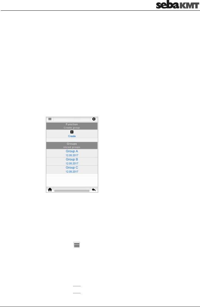
The display area is divided in two. Under the Function section you will find the functions for creating logger groups. Under Groups, all created logger groups are listed.
Creating a group ► Tap Create.
A dialogue window opens.
►Enter a name and a comment for the new group.
►Tap Create.
The dialogue window closes.
The newly created group now appears in the Groups list.
Deleting a group ► Tap the button |
|
. |
►In the context menu, tap Delete.
►Select the desired group in the Groups list.
►Confirm the security prompt with OK.
The group disappears from the group list. All data of the group are deleted from the PocketServer.
►Tap the button 
 .
.
17

LOG N-3
Adding loggers to the group
►In the Group list, select the corresponding group.
►Tap Edit group.
The display area is divided in two. In the Function section you will find the functions for editing the group. In the Devices section, all loggers in this group are listed.
Option 1: Entry of the ID
►Tap Add.
A dialogue window opens.
►Enter the identification number (ID) of the logger.
►Tap Add.
The dialogue window closes. The newly created logger now appears in the device list.
Option 2: Automatic detection
►Tap Auto-Detection.
A dialogue window opens. You can enter a comment on the logger or allow automatic creation of a comment.
►Tap Start.
►Switch the logger on.
The ID of the device is recognised by the PocketServer. The logger now appears in the device list.
►Tap Stop auto-detection.
Deleting loggers from |
► Tap the button |
. |
the group |
►In the context menu, tap Delete.
►Select the desired logger in the Devices list.
►Confirm the security prompt with OK.
The logger disappears from the device list. All data of the logger are deleted from the PocketServer.
►Tap the button 
 .
.
4.1.2Single loggers
To create or edit single loggers in the PocketServer, proceed as follows:
►In the start screen, tap LOG N-3.
►Tap Single device.
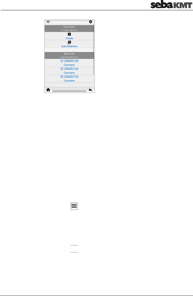
The display area is divided in two. In the Function section you will find the functions for creating loggers. In the Devices section, all created loggers are listed with ID and comment.
18
LOG N-3
Creating loggers Option 1: Entry of the ID
►Tap Create.
A dialogue window opens.
►Enter the identification number (ID) of the new logger. You can also enter a comment on the device.
►Tap Create.
The dialogue window closes. The newly created logger now appears in the Devices list.
Option 2: Automatic detection
►Tap Auto-Detection.
►Switch the logger on.
The ID of the logger is recognised by the PocketServer. The logger now appears in the Devices list.
►Tap Stop auto-detection.
Deleting loggers |
|
► Tap the button |
. |
►In the context menu, tap Delete.
►Select the desired logger from the Devices list.
►Answer the confirmation prompt with OK.
The logger disappears from the device list. All data of the logger are deleted from the PocketServer.
►Tap the button 
 .
.
19

LOG N-3
4.2Reading the measured data
4.2.1Patrol
Requirement:
It is recommended that you connect the optional external wireless module LOG RI+ to the PocketServer because the limited range of the internal wireless module only allows a limited patrol.
Procedure:
►In the start screen, tap LOG N-3.
►Tap Patrol mode.
►Select the desired logger group in the Groups list.
►Tap Start Patrol mode.
The patrol begins. The radio LED on the LOG RI+ or on the PocketServer lights up. The PocketServer searches for loggers of the group within radio range. Once a logger is detected, its data is received and stored. The screen shows which loggers have already been received and which have not.
With the Stop Patrol mode button, you can stop the patrol at any time. Otherwise, the patrol process continues until all the loggers in the group have been recognized and received. A success message appears on the screen. The radio module is deactivated. The radio LED goes off.
The received measurement data can be found as a data record in the Data list. It can be accessed and displayed there.
4.2.2Reading out a Lift&Shift group
Requirement:
The loggers must not have been switched off since the measurement.
Procedure:
►In the start screen, tap LOG N-3.
►Tap Lift&Shift.
►Select the desired logger group in the Groups list.
►Tap Read group.
The measurement data is read. The progress of the operation is shown on the screen. At the end, a message informs you which loggers of the group were read out successfully and which were not. If necessary, repeat the procedure.
 INFO
INFO
All loggers must be in wireless range. The ideal distance is approximately 2 m between PocketServer and loggers.
The received measurement data can be found as a data record in the Data list. It can be accessed and displayed there.
20
LOG N-3
4.2.3Reading out single loggers
To read out measured data from an individual logger, proceed as follows:
►In the start screen, tap LOG N-3.
►Tap Single device.
►Select the desired logger from the Devices list.
►Tap Measurement data.
The connection to the logger is established. The data is received by the PocketServer and displayed on the screen.
After closing the measurement data display, you will find this data record in the Data list. It can be accessed and displayed there at any time.
4.3Displaying measurement data
All read measured data is stored in the PocketServer and can be accessed and displayed at any time.
4.3.1Data of a Patrol group
To access the measured data of a Patrol group, proceed as follows:
►In the start screen, tap LOG N-3.
►Tap Patrol mode.
►Select the desired logger group in the Groups list.
►Select the desired measured data from the Data list. On the screen, the Session area opens.
On the left, all loggers are listed using their ID.
In the middle, a coloured symbol indicates whether the logger is in the alarm state.
GREEN … no alarm.
RED … alarm! Leak threshold exceeded
On the right, you will find the minimum ESA value of the respective logger.
Displaying the When you tap the coloured icon next to a logger ID, an additional line is shown/hidden. minimum values
In this line you will find:
Level and frequency of the leak noise of this logger
21
LOG N-3
The set alarm threshold of this logger
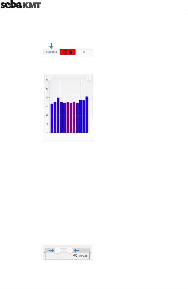
Displaying If you tap the ID of a logger in the alarm state, the complete measurements of this measurements logger are accessed.
The measured data display opens.
X-axis … course of measurement over time
Y-axis … level in dB
Each bar represents a single measurement.
The height of the bar represents the measured level.
The colour of the bar represents the measured frequency.
0 Hz  3300 Hz
The horizontal green line represents the set alarm threshold.
Editing the displays Zoom
You can narrow the chart view to any time range.
Option 1:
►Touch a point on the diagram and slide your finger to the side to highlight the desired area.
Option 2:
► Slide the two control elements to the left/right at the top of the diagram.
Reset:
► Tap Show all to reset the view.
22
LOG N-3
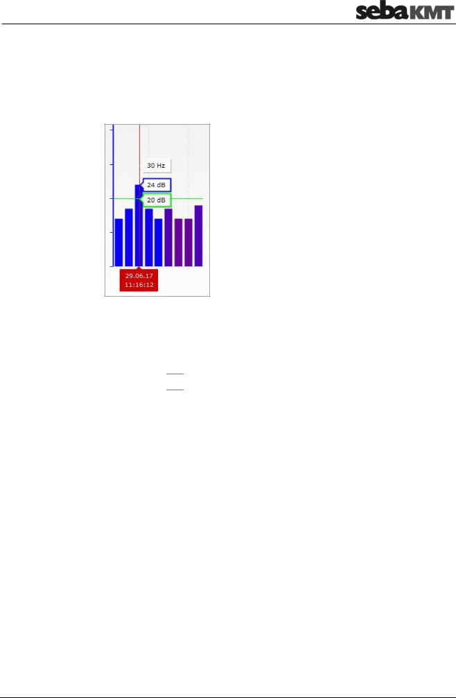
Individual values
For each individual measurement in the digram, you can find the measured level (dB), the frequency (Hz) and the exact time of the measurement.
► Touch the desired bar in the diagram.
A vertical red line appears (cursor). The values can be read on this line.
The green highlighted box indicates the alarm threshold (here: 20 dB).
Legend
You can view additional information about the diagram view.
►Tap the button 
 .
.
►In the context menu, tap Legend.
Above the digram, the Info area opens. It provides, along with other information, a colour scale for easier classification of the frequency values.
To close the area again, repeat the two steps.
23
LOG N-3
4.3.2Data of a Lift&Shift group
To access the measured data of a Lift&Shift group, proceed as follows:
►In the start screen, tap LOG N-3.
►Tap Lift&Shift.
►Select the desired logger group in the Groups list.
►Select the desired measured data from the Data list.
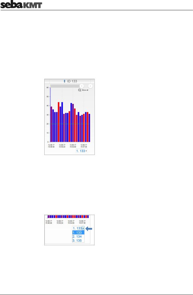
The measured data display opens. The measured values of the first logger of the group are displayed in a diagram.
X-axis … course of measurement over time
Y-axis … level in dB
Each bar represents a single measurement. The height of the bar represents the level.
The colour of the bar represents the frequency.
0 Hz  3300 Hz
The horizontal green line represents the set alarm threshold.
Changing loggers Below the diagram, there is a drop-down list. It contains all loggers, listed using their ID.
► To open the measured data of a logger, tap on the desired logger in the list.
Zoom You can narrow the chart view to any time range.
Option 1:
►Touch a point on the diagram and slide your finger to the side to highlight the desired area.
24
 Loading...