

Page 1
Mess- und Ortungstechnik
Measuring and Locating Technologies
Leitungsortung
Line Locating
Rohrleitungsnetze
Water Networks
Kommunikationsnetze
Communication Networks
Elektrizitätsnetze
Power Networks
Issue: 1 (09/2008)
5 V
Alarm IN
Operating Instructions
Data Logger
Sebalog D
Page 2

Page 3
1-3
Consultation with SebaKMT
The present system manual has been designed as an operating guide and for reference. It is meant to answer your
questions and solve your problems in as fast and easy a way as possible. Please start with referring to this manual
should any trouble occur.
In doing so, make use of the table of contents and read the relevant paragraph with great attention. Furthermore,
check all terminals and connections of the instruments involved.
Should any question remain unanswered, please contact:
Seba Dynatronic
Mess- und Ortungstechnik GmbH
Hagenuk KMT
Kabelmesstechnik GmbH
Dr.-Herbert-Iann-Str. 6
D - 96148 Baunach
Phone: +49 / 9544 / 68 – 0
Fax: +49 / 9544 / 22 73
Röderaue 41
D - 01471 Radeburg / Dresden
Phone: +49 / 35208 / 84 – 0
Fax: +49 / 35208 / 84 249
E-Mail: sales@sebakmt.com
http://www.sebakmt.com
SebaKMT
All rights reserved. No part of this handbook may be copied by photographic or other means unless SebaKMT have before-hand
declared their consent in writing. The content of this handbook is subject to change without notice. SebaKMT cannot be made
liable for technical or printing errors or shortcomings of this handbook. SebaKMT also disclaim all responsibility
for damage resulting directly or indirectly from the delivery, supply, or use of this matter.
Page 4

1-4
Terms of Warranty
SebaKMT accept responsibility for a claim under warranty brought forward by a customer for a product sold by
SebaKMT under the terms stated below.
SebaKMT warrant that at the time of delivery SebaKMT products are free from manufacturing or material defects
which might considerably reduce their value or usability. This warranty does not apply to faults in the software
supplied. During the period of warranty, SebaKMT agree to repair faulty parts or replace them with new parts or
parts as new (with the same usability and life as new parts) according to their choice.
SebaKMT reject all further claims under warranty, in particular those from consequential damage. Each component
and product replaced in accordance with this warranty becomes the property of SebaKMT.
All warranty claims versus SebaKMT are hereby limited to a period of 12 months from the date of delivery. Each
component supplied by SebaKMT within the context of warranty will also be covered by this warranty for the
remaining period of time but for 90 days at least.
Each measure to remedy a claim under warranty shall exclusively be carried out by SebaKMT or an authorized
service station.
To register a claim under the provisions of this warranty, the customer has to complain about the defect, in case of
an immediately detectable fault within 10 days from the date of delivery.
This warranty does not apply to any fault or damage caused by exposing a product to conditions not in accordance
with its specification, by storing, transporting, or using it improperly, or having it serviced or installed by a workshop
not authorized by SebaKMT. All responsibility is disclaimed for damage due to wear, will of God, or connection to
foreign components.
For damage resulting from a violation of their duty to repair or re-supply items, SebaKMT can be made liable only
in case of severe negligence or intention. Any liability for slight negligence is disclaimed.
Page 5

1-5
Contents
1 Safety Advices..................................................................................................................1-7
2 Technical Description......................................................................................................2-8
2.1 Technical Data ..................................................................................................................... 2-8
2.2 Scope of Delivery ................................................................................................................. 2-9
2.3 Available Configurations....................................................................................................... 2-9
2.4 Design ................................................................................................................................ 2-11
2.5 Accessories........................................................................................................................ 2-13
3 Commissioning the Logger...........................................................................................3-14
3.1 Configuring the Logger....................................................................................................... 3-14
3.2 Preparing the Logger for GSM Connectivity....................................................................... 3-14
3.3 Connecting the Logger....................................................................................................... 3-16
3.3.1 Connecting Sensors and Alarm Devices.................................................................... 3-16
3.3.1.1 Basics .................................................................................................................................3-16
3.3.1.2 Connection Equipment for Single-channel Loggers........................................................... 3-18
3.3.1.3 Connection Equipment for Multi-channel Loggers ............................................................. 3-19
3.3.1.4 Wiring Diagram Examples.................................................................................................. 3-21
3.3.2 Connecting a Tube to an Internal Pressure Sensor................................................... 3-25
3.4 Commissioning the Logger................................................................................................. 3-26
3.4.1 Positioning the Logger ............................................................................................... 3-26
3.5 Positioning the GSM Antenna ............................................................................................ 3-26
3.6 Switching the Logger On/Off .............................................................................................. 3-27
4 Setting Up the Software.................................................................................................4-28
4.1 System Requirements........................................................................................................ 4-28
4.2 Installing the Software........................................................................................................ 4-28
4.3 Connecting the Logger to the PC....................................................................................... 4-29
4.3.1 Radio Communication via E-Box ............................................................................... 4-29
4.3.2 Connecting the Logger via Direct Connection............................................................ 4-30
4.4 Starting the Software.......................................................................................................... 4-31
4.5 Registering a Logger.......................................................................................................... 4-32
4.5.1 Adding / Deleting a Logger......................................................................................... 4-32
4.5.2 Adding / Deleting a Group.......................................................................................... 4-33
5 Configuring the Logger.................................................................................................5-35
5.1 Selecting the Logging Interval............................................................................................ 5-36
5.2 Sensor Configuration.......................................................................................................... 5-36
5.2.1 Sensor Type............................................................................................................... 5-37
Page 6

1-6
5.2.1.1 Configuring a „Customer Specific“ Sensor .........................................................................5-37
5.2.1.2 Input Type Examples..........................................................................................................5-38
5.2.2 Configuring Alarm Conditions (Threshold Monitoring)................................................ 5-40
5.2.3 Finishing the Configuration.........................................................................................5-41
5.3 Configuring the Switching Inputs (Alarm Inputs)................................................................. 5-42
5.4 Configuring the Radio Communication............................................................................... 5-44
5.4.1 SIM Card Configuration..............................................................................................5-46
5.4.2 Configuring the Internet Access Point of the Network Operator................................. 5-46
5.4.3 Email Configuration....................................................................................................5-46
5.4.4 FTP Settings...............................................................................................................5-47
5.4.5 SMS Destinations.......................................................................................................5-47
5.4.6 Summary Messages...................................................................................................5-47
5.4.7 Testing the GSM Settings ..........................................................................................5-48
5.4.7.1 Testing SMS / Email Transmission.....................................................................................5-48
5.4.7.2 Testing FTP Data Transfer .................................................................................................5-50
5.4.8 Finishing the Communication Setup...........................................................................5-50
5.5 Start Time........................................................................................................................... 5-50
5.6 Memory Mode..................................................................................................................... 5-51
5.7 State ...................................................................................................................................5-51
5.8 Finishing the Configuration................................................................................................. 5-51
6 Retrieving and Evaluating Data.....................................................................................6-52
6.1 Retrieving Data from the Logger......................................................................................... 6-52
6.2 Collecting Data from the FTP Server.................................................................................. 6-53
6.3 Evaluating Measured Data ................................................................................................. 6-54
7 Miscellaneous Functions...............................................................................................7-56
7.1 Identifying Loggers ............................................................................................................. 7-56
7.2 Real-Time Measurement.................................................................................................... 7-56
7.3 Setting the Clock................................................................................................................. 7-57
7.4 CSV Export......................................................................................................................... 7-57
7.5 Deleting Logged Data......................................................................................................... 7-57
7.6 Firmware............................................................................................................................. 7-58
8 Replacing the Batteries..................................................................................................8-59
Page 7
1-7
1 Safety Advices
Safety precautions This manual contains basic advice for the installation and operation of the Sebalog D.
It is essential to make this manual accessible to the authorized and skilled operator.
He needs to read this manual closely. The manufacturer is not liable for damage to
material or humans due to non-observance of the instructions and safety advices
provided by this manual.
Locally applying regulations must be observed.
Special transportation
requirements
The lithium batteries of the Sebalog D are dangerous goods. The transport of the
batteries itself and of devices which contain such batteries is subject to regulations
based on the UN Model Regulations “Transport of Dangerous Goods”
(ST/SG/AC.10-1).
Please inform yourself about the transportation requirements and follow them when
shipping the device.
General Cautions
•
The limits described under technical data may not be exceeded.
•
Do not drop the device or subject it to strong impacts or mechanical shocks!
•
Do not operate the device with a voltage unequal to the specified operating voltage!
•
Original accessories ensure safe operation of the equipment. It is not allowed and
the warranty is lost if other accessories than the original ones are used with the
equipment.
•
Cover the sockets on the top of the device always with the provided protection caps
,
if no cable is connected to the terminal. Otherwise, penetrating dirt and water may
damage the device.
CAUTION
!
Page 8

2-8
2 Technical Description
Intended application The Sebalog D is a compact, robust and extremely versatile data logger. The device
can record the readings of various sensor types in user-defined intervals. The
collected data can be periodically transmitted to a FTP server or read out with a PC or
special equipment.
Depending on the configuration of the logger, up to 4 freely programmable channels
can be connected to sensors for data recording.
Furthermore, the logger can be used to trigger user-defined alarm signals (e.g. signal
lights, SMS or email), if a threshold is exceeded or special alarm equipment is
triggered.
2.1 Technical Data
Depending on the configuration, the Sebalog D is specified by the following
parameters:
Parameter Value
Communication USB interface
Wireless, 868/915 MHz
GSM/GPRS modem, 850/900/1800/1900 MHz
Inputs / outputs
1, 2 or 4 freely programmable channels, analog or digital
(0…5 V / 0…20 mA / pulse / frequency)
up to 2 switching inputs (alarm trigger)
up to 2 switching outputs (alarm installation)
up to 2 connectors for internal pressure sensors
Internal pressure
sensors
up to 2 sensors (optional)
(10 bar / 16 bar / 25 bar / 40 bar)
Accuracy +/- 0,1%
Interval 1 s … 31 days (programmable)
Memory
2 MByte internal memory (expandable via SD)
Block or roll memory
Alarm - switching input(s) and threshold monitoring
- triggering of switching output(s) and SMS / email
notifocation
Operating voltage 12 V DC
Accumulator Internal lithium battery
Operating
temperature
-10°C … +50°C
Dimensions
(L x W x H)
115 x 115 x 180 mm
Weight 0,8 kg
Protection class IP 68
Page 9

2-9
2.2 Scope of Delivery
Besides of the logger unit and a magnet, the Sebalog D package contains a CD with
the following content:
• SebaDataView configuration and readout software
• Driver
• Sebalog D information materials
Depending on the configuration of the logger, the scope of delivery may contain even
more accessories which can also be ordered from SebaKMT (see section 2.5).
2.3 Available Configurations
Introduction The Sebalog D is available in a wide variety of configurations. It ranges from a basic
version with 1 channel to a full equipped version with 4 channels, integrated pressure
sensors and an internal GSM modem.
The feature options can be combined in almost any possible way which leads to the
many configurations listed in the table below. By means of the item number (PN) on
the bottom of the logger you can identify the type of your device:
Single-channel versions
Item number Type Item number Type
820013543 LOG D1-B 820013549 LOG D1-GSM-P1-16
820013544 LOG D1-P1-16 820013550 LOG D1-GSM-P1-25
820013545 LOG D1-P1-25 820013551 LOG D1-GSM-P1-40
820013546 LOG D1-P1-40 820013552 LOG D1-I-B
820013547 LOG D1-GSM 820013559 LOG D1-I-GSM
2-channel versions
Item number Type Item number Type
820013506 LOG D2-B 820013522 LOG D2-GSM-P2-16
820013507 LOG D2-P1-16 820013523 LOG D2-GSM-P2-25
820013508 LOG D2-P1-25 820013525 LOG D2-GSM-P2-40
820013510 LOG D2-P1-40 820013527 LOG D2-I-B
820013512 LOG D2-P2-16 820013530 LOG D2-I-P1-16
820013515 LOG D2-P2-25 820013531 LOG D2-I-P1-25
820013516 LOG D2-P2-40 820013532 LOG D2-I-P1-40
820013518 LOG D2-GSM 820013536 LOG D2-I-GSM
820013519 LOG D2-GSM-P1-16 820013537 LOG D2-I-GSM-P1-16
820013520 LOG D2-GSM-P1-25 820013538 LOG D2-I-GSM-P1-25
820013521 LOG D2-GSM-P1-40 820013539 LOG D2-I-GSM-P1-40
Page 10
2-10
4-channel versions
Item number Type Item number Type
820012348 LOG D4-B 820012354 LOG D4-I-B
820012349 LOG D4-P1-16 820012355 LOG D4-I-P1-16
820013478 LOG D4-P1-25 820013487 LOG D4-I-P1-25
820013479 LOG D4-P1-40 820013488 LOG D4-I-P1-40
820012350 LOG D4-P2-16 820012356 LOG D4-I-P2-16
820013480 LOG D4-P2-25 820013489 LOG D4-I-P2-25
820013481 LOG D4-P2-40 820013490 LOG D4-I-P2-40
820012351 LOG D4-GSM 820012357 LOG D4-I-GSM
820012352 LOG D4-GSM-P1-16 820012358 LOG D4-I-GSM-P1-16
820013482 LOG D4-GSM-P1-25 820013491 LOG D4-I-GSM-P1-25
820013483 LOG D4-GSM-P1-40 820013492 LOG D4-I-GSM-P1-40
820012353 LOG D4-GSM-P2-16 820012359 LOG D4-I-GSM-P2-16
820013485 LOG D4-GSM-P2-25 820013474 LOG D4-I-GSM-P2-25
820013486 LOG D4-GSM-P2-40 820013493 LOG D4-I-GSM-P2-40
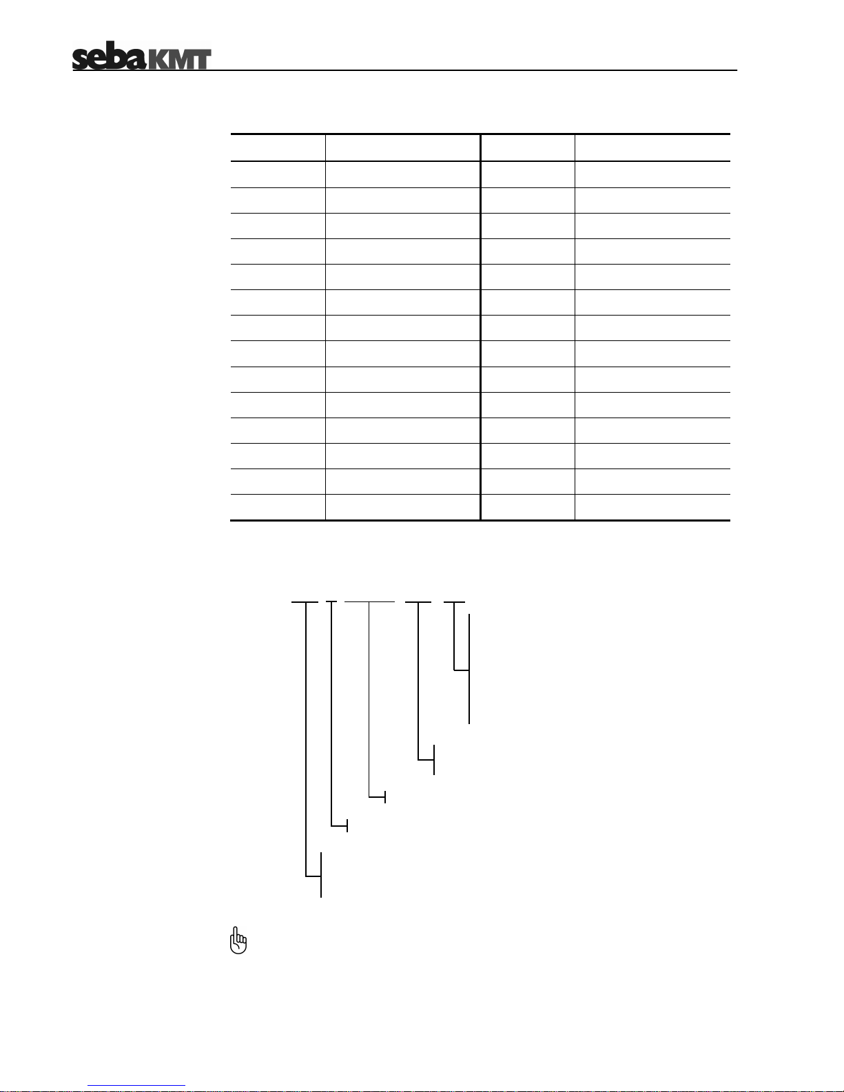
Type number The type number consists of the following segments:
Due to the large amount of possible configurations, this manual cannot state
explicitly whether or not a described function applies to your device. Please use
the information provided within this section to identify the specific capabilities of
your logger.
10 … The internal pressure sensors have a measuring
range of 10 bar
16 … The internal pressure sensors have a measuring
range of 16 bar
25 … The internal pressure sensors have a measuring
range of 25 bar
40 … The internal pressure sensors have a measuring
range of 40 bar
LOG D4
-I-
GSM
-
P2
-
16
D1 … the logger has 1 logging channel
D2 … the logger has 2 logging channels
D4 … the logger has 4 logging channels
The logger can be connected to a sensor via current loop
the logger contains an internal GSM modem
P1 …the logger contains one internal pressure sensor
P2 …the logger contains two internal pressure sensors
Page 11
2-11
2.4 Design
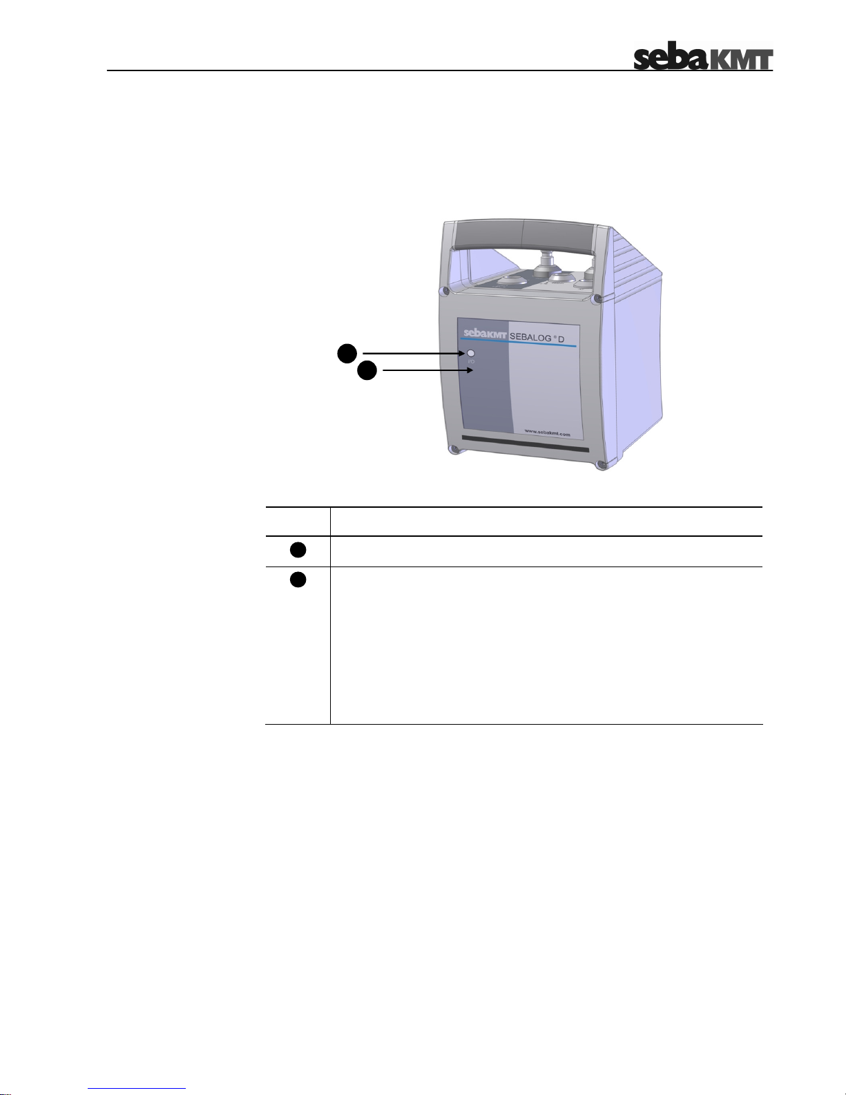
Controls and indicators The following figure shows all the front panel operating controls and indicators. The unit
is in protection class IP 68:
The Sebalog D consists of the following operating controls and indicators:
Item Description
On/off contact area
I/O control lamp
not lit: Logger is switched off
green (flashing): Logger is switched on and in energy saving mode
green (permanent): Logger is switched on and a radio link to a
PC (E-Box) is established
orange (permanent): Data transfer takes place
red (for a moment): Logger is switching off
1
2
1
2
Page 12
2-12
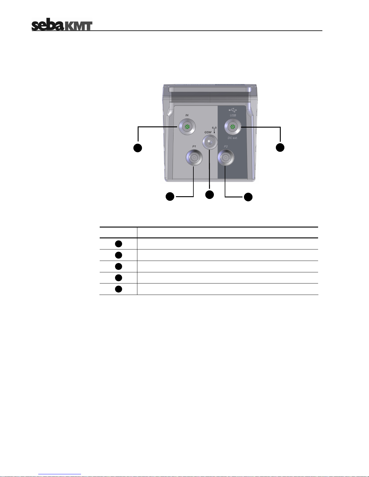
Connectors The following figure shows the connectors of the Sebalog D which are placed on top of
the device. While the USB socket is always part of the assembly, it depends on the
configuration of the logger whether the other connectors are existent:
The Sebalog D offers the following connectors:
Item Description
IN socket
USB / DC ext. socket
internal pressure sensor P1
internal pressure sensor P2
GSM antenna socket
4
7
6
5
3
5
3 4
6
7
Page 13

2-13
2.5 Accessories
In addition to the standard scope of delivery, there is a large amount of optional
accessory parts which can be ordered from SebaKMT.
The following table describes all available accessory parts:
Accessory part Description Item number
Connection cable
VK 75, green
- for connecting the logger to up to 4
sensors
- must be connected to the
IN socket
820012449
Connection cable
VK 76, red
- for connecting a sensor and up to 2
switching inputs / outputs (alarming)
- must be connected to the
USB / DC ext. socket
820012450
Connection cable
VK 77 USB, red
- for connecting the logger to a PC
- must be connected to the
USB / DC ext. socket
820012451
E-Box USB
Allows wireless data transfer between
the logger and a PC within a range of
about 100 m.
820009270
USB cable (1 m) For connecting the E-Box to the PC 820008969
Antenna for E-Box Spare part 122010014
Reader Box For wireless on-site data readout
without PC
on request
GSM antenna with
connection cable (3 m)
- only for logger with GSM modem
- must be connected to the
GSM socket
820012452 (cable)
Coupler
(1/4” male thread)
For connecting a tube with ¼” female
thread to an internal pressure sensor
820014883
AD-21
External pressure sensor Different measuring ranges available on request
External accumulator External power supply for the logger on request
Charger For charging the external
accumulator (see above)
on request
7
3
4
4
Page 14
3-14
3 Commissioning the Logger
3.1 Configuring the Logger
Prior to its on-site installation, the logger must be properly configured using the
supplied SebaDataView software. In doing so, the logger has to be provided with the
channel allocation, the alarm conditions and the wireless connection parameters
among other things.
(For a detailed description of the logger configuration, please refer to chapter 5).
3.2 Preparing the Logger for GSM Connectivity
If the data collected by the logger should be periodically transferred to a FTP server
or if an alarm notification via email / SMS is required, the following steps must be
performed in order to prepare a logger (with built-in GSM modem) for GSM
connectivity:
Step Action
1
In order to get a SIM card enabled for data transfer via GPRS, you have
to close a suitable contract with a mobile phone service provider.
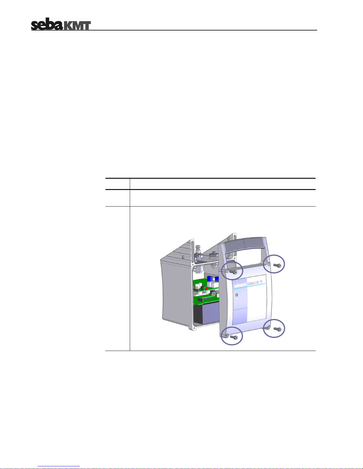
2
Loosen the four marked screws with a M3 allen key or with a crosstip
screwdriver respectively (depending on the logger type) and remove
the front panel.
Page 15

3-15
(Continuation from previous page:)
Step Action
Insert the SIM card into the slot as shown in the figure below. The card
has to snap into the spring mechanism.
If you need to release the card, gently press its protruding edge.
3
Please be careful not to damage any electrical parts within the
logger.
Attach the front panel to the housing again.
4
In order to ensure the total protection against water and dust
ingress compliant with IP 68, the following instructions must be
observed:
• If the logger is older then six months and if the front panel has
not been changed during the last six months, a new front panel
including a new rubber seal must be installed. A new front
panel can be ordered from SebaKMT.
• The rubber seal and the contact surfaces of the housing must
be free of dirt.
• Be careful not to jam the housing parts against each other.
• Tighten the screws with a torque of 1 Nm.
5
Connect the supplied GSM antenna with the GSM socket . Make
sure that the guide on the plug fits in the groove in the socket and that
you feel the plug latch in.
6
Make sure that the GSM settings have been properly configured (see
section 5.4).
7
(cut edge to the left)
Page 16

3-16
3.3 Connecting the Logger
Depending on its configuration, the following peripheral and measring devices can be
connected to a logger:
• up to 4 sensors can be attached and the data can be logged (e.g. pressure,
flow velocity)
• up to 2 alarm-triggering devices (e.g. a light barrier) can be connected to the
switching inputs
• up to 2 devices (e.g. signal lamp, pump) can be connected to the switching
outputs and can be triggered in the case of an alarm
• up to two tubes can be directly connected to the internal pressure sensors
Depending on the type of sensors / alarm devices connected to the Sebalog D, the
appropriate parameter values have to be provided to the logger using the
SebaDataView software. For a detailed description of the necessary configuration
steps, please refer to section 5.2.
3.3.1 Connecting Sensors and Alarm Devices
3.3.1.1 Basics
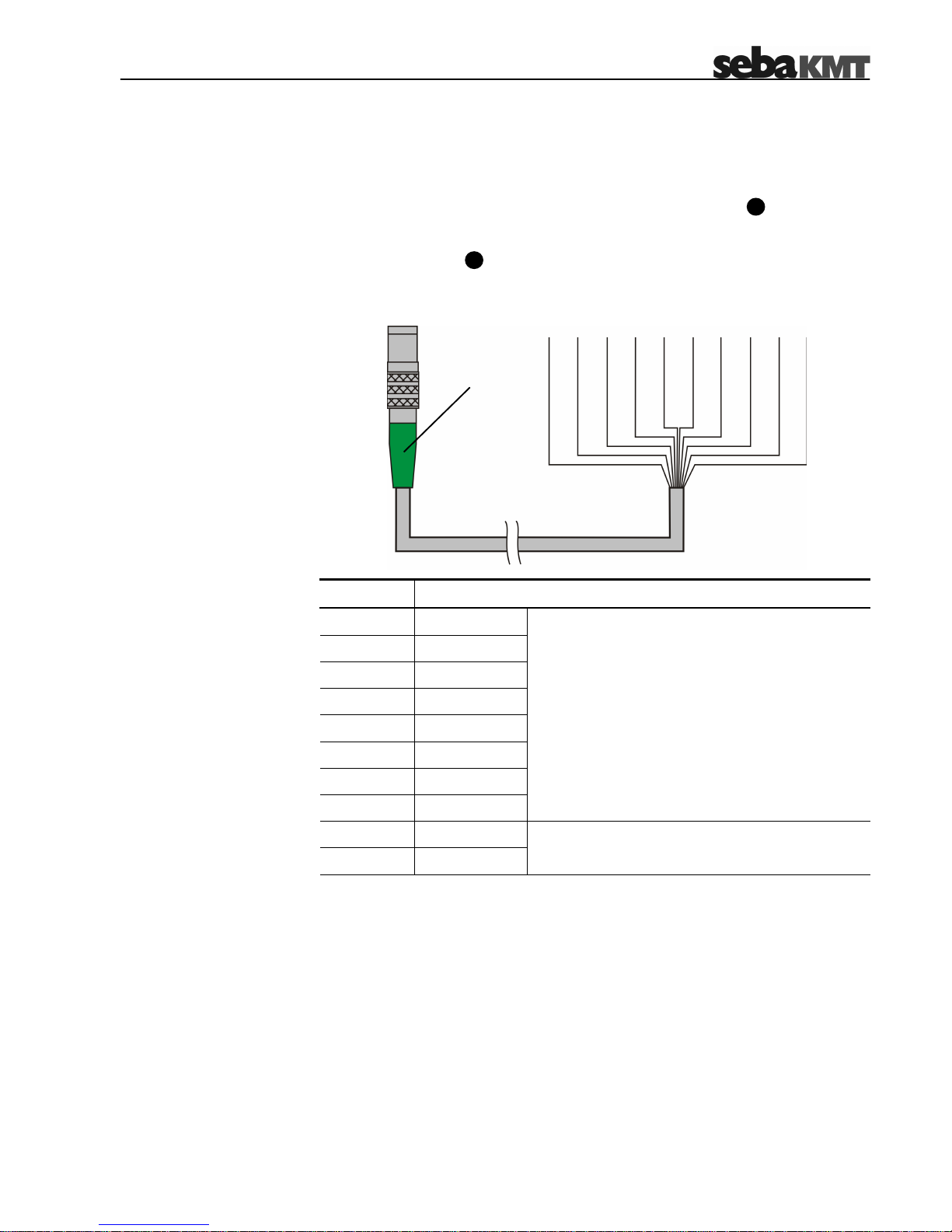
Introduction One end of the VK 75 / VK 76 connection cables used for connecting equipment to
the logger is uncoated and ten colour-coded wires stick out of it. According to its
colour, each of these wires represents a specific input / output of the logger and can
be directly connected to the respective terminal of a peripheral device (e.g. a sensor).
If no adequate terminals are existent, a luster terminal or other accessories can be
used. A proper electrical insulation must be ensured.
For the basic logger version with only one channel, all connections are established
via the VK 76 connection cable attached to the USB / DC ext. socket .
For loggers with 2 or even 4 channels only the switching inputs/outputs and the
external power supply are connected via the VK 76 connection cable. Any
connections to sensors are established via the VK 75 connection cable attached to
the IN socket .
The channels are assigned in numeric order which means that for a 2-channel
logger, the channels 1 and 2 have to be used for the connection setup.
3
4
Page 17

3-17
Fixed channel allocations Due to the internal wiring of the logger, current loops can only be connected to the
channels 2 and 4.
The internal pressure sensors P1 and P2 are always linked to channel 1 and 3. If the
logger is equipped with one or two internal pressure sensors, the respective channels
are in use and must not be connected to external sensors.
Corresponding to these conventions, the following channel allocations apply:
Channel 1 Channel 2 Channel 3 Channel 4
Single-channel Logger
Int. pressure sensor
X
Current loop
X
2-channel Logger
Int. pressure sensor P1
X
Int. pressure sensor P2
X
Current loop
X
4-channel Logger
Int. pressure sensor P1
X
Int. pressure sensor P2
X
First current loop
X
Second current loop
X
Page 18
3-18
3.3.1.2 Connection Equipment for Single-channel Loggers
Introduction Loggers with only one channel (LOG D-1) can be connected to one sensor, a
switching input and a switching output. All of these connections can be established
with only one connection cable (VK 76) attached to the USB / DC ext. socket .
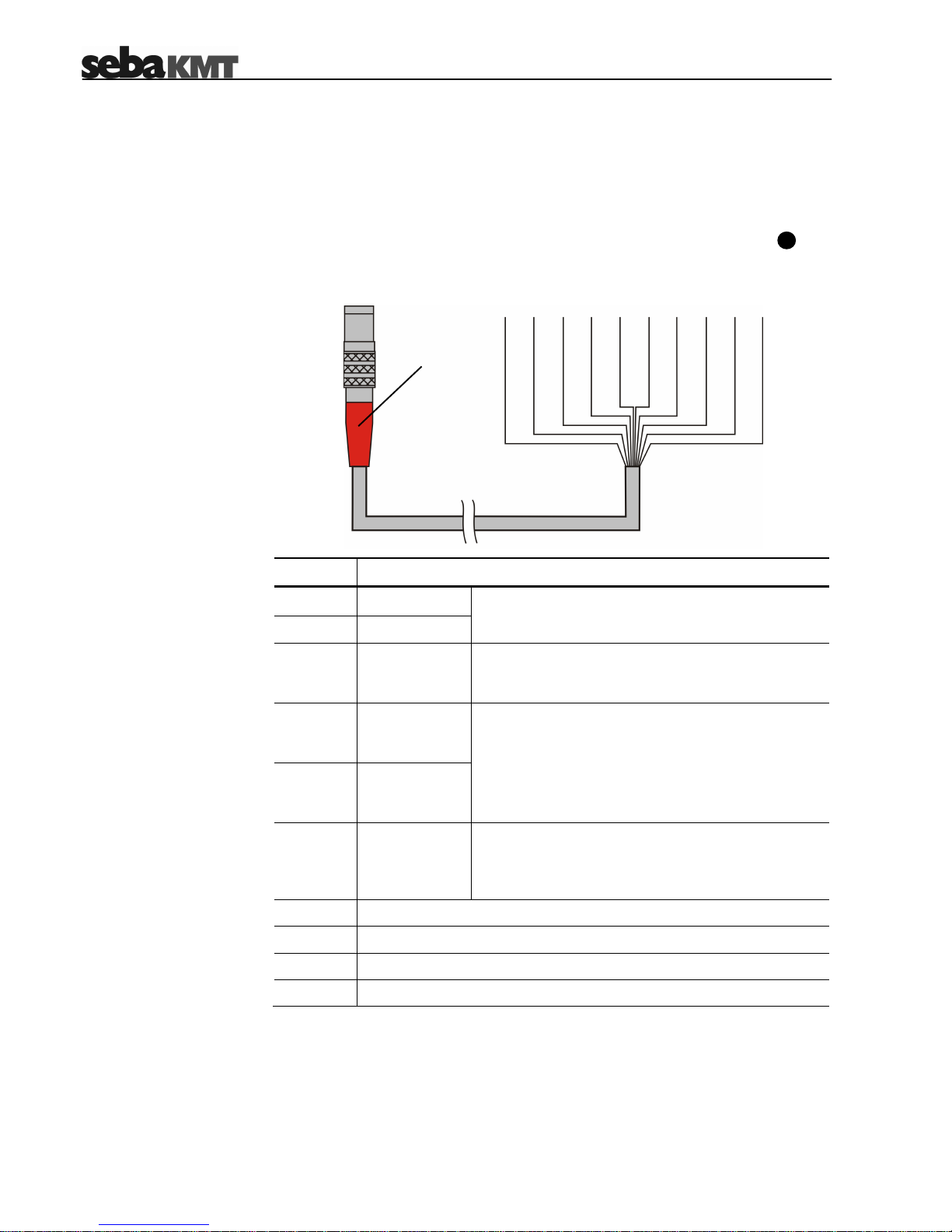
VK 76 pin assignment in
combination with
single-channel loggers
In combination with a single-channel logger, the VK 76 connection cable has the
following pin assignment:
Wire Description
white
Channel +
brown
Channel –
Channel a sensor can be connected to.
green
Switching
input 2
An alarm-triggering device with a voltage output of
0 … 5 V can be connected between this wire and
the purple wire (GND).
yellow
Switching
output
(relay 2) OUT
pink
Switching
output
(relay 2) IN
An electric circuit with an external DC power supply
up to 12 V / 1 A can be connected between these
two wires. If the internal relay is triggered by an
alarm event, the circuit is closed and the connected
load is activated / triggered.
red
External
power supply
An external power supply with 12 V DC can be
connected between this wire and the purple wire
(GND). The internal battery cannot be charged by an
external power supply.
purple
GND
grey
not used
blue
not used
black
not used
4
red
(to be connected to
USB / DC ext.)
Page 19
3-19
3.3.1.3 Connection Equipment for Multi-channel Loggers
Introduction
Multi-channel loggers are equipped with the additional IN socket up to 4 external
sensors can be connected to (via the VK 75 connection cable). The switching
inputs/outputs and the external power supply have to be connected to the
USB / DC ext. socket (via the VK 76 connection cable).
VK 75 pin assignment In combination with a multi-channel logger, the VK 75 connection cable has the
following pin assignment:
Wire Description
white
Channel 1 +
brown
Channel 1 –
green
Channel 2 +
yellow
Channel 2 –
grey
Channel 3 +
pink
Channel 3 –
blue
Channel 4 +
red
Channel 4 –
Channels up to 4 sensors can be connected to.
black
5 V OUT
purple
GND
DC power supply for sensors or other loads
(U = 5 V / I
max
= 20 mA)
4
3
green
(to be connected to IN)
Page 20

3-20
VK 76 pin assignment in
combination with multi-
channel loggers
In combination with a multi-channel logger, the VK 76 connection cable has the
following pin assignment:
Wire Description
white
Switching
Input 1
green
Switching
Input 2
An alarm-triggering device with a voltage output of
0 … 5 V can be connected between a switching
input and the purple wire (GND).
brown
Switching
output
(relay 1) OUT
yellow
Switching
output
(relay 2) OUT
pink
Switching
outputs IN
An electric circuit with an external DC power
supply up to 12 V / 1 A can be connected to each
switching output. If an internal relay is triggered by
an alarm event, the respective circuit is closed and
the connected load is activated / triggered.
red
External
power supply
An external power supply with 12 V DC can be
connected between this wire and the purple wire
(GND). The internal battery cannot be charged by
an external power supply.
purple
GND
grey
not used
blue
not used
black
not used
red
(to be connected to
USB / DC ext.)
Page 21

3-21
3.3.1.4 Wiring Diagram Examples
Introduction The examples described in the following pages can be realized with any type of
logger even with the basic version with only one channel. For multi-channel loggers,
these examples can be combined in many ways depending on the logger
configuration. A 4-channel logger, for example, can be connected to up to four
different types of sensors and can be included in up to two alarm loops.
Depending on the sensor, the actual wiring diagram and the terminal designation
may differ. For some sensor types, it is necessary to integrate a resistance into the
connection setup in order to dampen or amplify the output signal. Please refer to the
respective sensor manual for detailed information.
Connecting a sensor with
the output signal type
voltage
The following example describes how to connect a sensor with a 0 … 5 V voltage
output:
Connecting a sensor with
the output signal type
current
The following example describes how to connect a sensor to a 0 … 20 mA or
4 … 20 mA current loop:
Current loops can only be connected to loggers which are capable of analyzing
this type of signal. Please check the configuration of your device (see
section 2.3).
A current loop can only be connected to channel 2 or 4.
5 V OUT
Channel +
GND
Channel –
Logger
I +
I –
Sensor
Sensor
Logger
5 V IN
Signal
GND
5 V OUT
Channel +
GND
Channel –
Page 22

3-22
Connecting a sensor with
the output signal type
frequency
The following examples describe how to connect a sensor with a 0 Hz … 1000 Hz
frequency output.
Example 1: the logger does not supply the operating voltage for the sensor:
Example 2: the logger supplies the operating voltage for the sensor:
Sensor
Logger
5 V OUT
Channel +
GND
Channel –
5 V IN
GND
Signal
Sensor
Logger
5 V OUT
Channel +
GND
Channel –
GND
Signal
10 k
10 k
Page 23

3-23
Connecting a sensor with
the output signal type
pulse (reed contact)
The following examples describe how to connect a sensor with pulse output. These
types of sensors transmit a pulse to the logger whenever the value of the
measurement crosses a certain threshold.
Example 1: the logger does not supply the operating voltage for the sensor:
Example 2: the logger supplies the operating voltage for the sensor:
Sensor
Logger
5 V IN
Signal
GND
5 V OUT
Channel +
Channel –
GND
1k
Sensor
Logger
Signal
GND
5 V OUT
Channel +
Channel –
GND
1k
Page 24

3-24
Example of an alarm loop The following example shows an electrical circuit with DC power source connected to
the switching input of the loggers. If an alarm is raised by the alarm device (e.g. light
barrier) is activated, the circuit is closed and the switching input is triggered.
Depending on the alarm configuration, one or two of the internal relays are switched
in order to activate / trigger the load connected to the respective switching output (in
this case a signal lamp) and a SMS and / or email can be sent to predefined
receivers.
Alarms can also be triggered when the value of a monitored measurment crosses a
predefined threshold. Please refer to section 5.2 for detailed information on how to
configure the threshold monitoring.
configured
alarm trigger
Alarm device
GND
Alarm IN
Relay IN
Relay OUT
GSM
SMS
email
Logger
Page 25

3-25
3.3.2 Connecting a Tube to an Internal Pressure Sensor
A Sebalog D logger can be equipped with up to two internal pressure sensors
(optional 10 bar, 16 bar, 25 bar or 40 bar) where tubes can be connected to.
The sensors are capable of measuring the pressure of both liquid and gaseous
media. When connecting a tube to a sensor, the following instructions must be
observed:
• Pressure sensors are sensitive to overpressure. Do not exceed the
measuring range in order to avoid irreparable damage to the sensor.
• Make sure no dirt or rust can ingress inside the sensors. In case of doubt,
use a filter.
• There must not be any water inside the sensor. Otherwise, frost can
damage the sensor.
• After a sensor has been in use or in storage for a longer period, it must be
cleaned with compressed air.
In order to connect a tube to the nipple ( or ) of an internal pressure sensor, the
tube has to be equipped with a coupler compatible to Rectus 21 (5 mm nominal
diameter).
A coupler for tubes with ¼“ female thread can be ordered from SebaKMT.
6 5
Page 26

3-26
3.4 Commissioning the Logger
3.4.1 Positioning the Logger
Thanks to its IP68 protection class, the logger housing is protected against the
ingress of dust and water and, thus, especially qualified for the operation in pipeline
shafts where it can be installed next to the measuring point.
The logger can be installed in vertical and horizontal position and can also be hung
up using, e.g., a cable tie.
During field installation, the following instructions must be observed in order to
ensure proper operation of the logger:
• Make sure that all connections to sensors of other peripheral devices are
established in a professional manner and that the connection points are
properly insulated.
• When you plug a connection cable (VK 75, VK 76 or VK 78) in the
respective socket, make sure you feel the plug latch in. Only proper and
positive locking connections provide protection against ingress of water and
ensure error-free data transfer.
• Care shall be taken to ensure that cables and their connections are not
subjected to tensile load.
• Do not hang the logger on its connection cables.
• Do not bend the connection cables.
• Make sure the logger is switched on before you leave the site.
3.5 Positioning the GSM Antenna
If your logger is equipped with a GSM modem and if you want to make use of the
GSM functionality, you have to observe the following instructions when positioning
the GSM antenna:
• The GSM antenna must be properly connected to the logger (see
section 3.2).
• Be aware that thick walls and other barriers do affect the signal strength
negatively.
• If the logger is installed underground, e.g. in a pipeline shaft, the antenna
should be positioned as near as possible to the ground surface.
Check the GSM connectivity using test functions of the SebaDataView software (see
section 5.4.7) right after the GSM antenna has been positioned. If no connection can
be established, a better position has to be found. If necessary, lead the antenna out
of the shaft and bury it a few centimetres under the ground surface.
Page 27

3-27
3.6 Switching the Logger On/Off
The logger is switched on by moving the supplied magnet in front of the contact
area . After the magnet switch has been activated, the I/O control lamp is lit
green for a moment and starts flashing green after the logger has been started up.
The device is now in energy saving mode.
Whenever a connection to an E-Box is established and whenever a data transfer
takes place, the logger automatically switches to data transfer mode.
After the logger has been switched on, it automatically starts logging as specified in
its configuration. The device keeps logging even if a data transfer takes place or an
alarm is triggered.
In order to switch the logger off, the magnet must be held in front of the contact
area for a few seconds while the I/O control lamp is lit orange. As soon as the
lamp switches to red, the magnet has to be taken away from the contact area.
Afterwards, the logger switches off and the lamp goes out.
Make sure to take the magnet away immediately after the lamp switches to red.
Otherwise, the logger reboots right after it has been switched off. Check that the
lamp does not start flashing green again.
1 2
2 1
Page 28

4-28
4 Setting Up the Software
The Sebalog D does not dispose of a display or any controls. Any communication
(configuration, data readout) with the device is performed using the SebaDataView
software.
4.1 System Requirements
Your machine must meet the following minimum system requirements in order to run
the SebaDataView software:
• PC or notebook with Windows XP® or higher
• min. Pentium compatible CPU
• min. 256 MB memory
• CD ROM drive
• USB interface
4.2 Installing the Software
To install the SebaDataView software insert the provided CD into your CD ROM
drive, execute the SDV-setup.exe and follow the instruction on the screen. The
application is installed to the C:\Program Files\SebaKMT\SebaDataView folder.
A database is created in the …\My Documents\SebaDataView\Data folder.
Do not delete any files from the Data folder.
If you would like to make the data available for other accounts, the complete
…SebaDataView\Data folder has to be transferred to the …\My Documents
folder of the respective account.
During start-up, the current version of the SebaDataView software is indicated.
Please check www.sebakmt.com regularly for updates.
Page 29

4-29
4.3 Connecting the Logger to the PC
If you would like to configure a logger or to retrieve data from a logger, a connection
to the logger has to be established first. This connection can be either established via
the VK 77 USB cable or via radio communication using the E-Box.
4.3.1 Radio Communication via E-Box
Introduction The E-Box, while connected to the PC via USB interface, offers you the possibility to
access all loggers in a range of up to 100 m (depending on the environmental
conditions) via radio link. That way, you are able to initiate a data transfer without
sitting next to the device.
If a logger receives a signal from the E-Box addressed to it, it changes from energy
saving mode to data transfer mode. During data transfer, the I/O control lamp
is lit green.
Design of the E-Box The following figure shows the E-Box:
Item Description
Antenna (replaceable)
USB socket
Control lamp
not lit: E-Box is not connected to a PC
red (flashing): E-Box is connected but not initialized
(e.g. due to missing driver)
green (permanent): E-Box is ready
orange (permanent): a data transfer takes place
red (permanent): E-Box is defective
2
10
9
8
10
8
9
Page 30

4-30
Connecting the E-Box Connect the E-Box to the USB port of your PC using the provided USB cable.
After the E-box has been connected to the PC or disconnected from the PC, it is
automatically switched on or off respectively. A green LED indicates that the E-Box is
supplied with power and ready for operation.
Driver Installation When the E-box is connected to a PC for the first time, the driver must be installed.
Windows operating systems (XP or later) will automatically identify the E-Box as new
hardware after it has been connected.
Follow the instructions on the screen and browse to the location
(C:\ Program Files \SebaKMT\SebaDataView\USBDriver) where the driver has been
automatically stored during software installation.
Windows may report that the driver is not certified and warn for possible danger.
Since the driver is not causing any danger for your system you can continue the
installation.
4.3.2 Connecting the Logger via Direct Connection
Connecting the logger To establish a direct connection to a PC, use the VK 77 USB cable supplied to
connect a USB port on the PC to the USB / DC ext. socket on the device. On the
device, make sure that the guide on the plug fits in the groove in the socket and that
you feel the plug latch in.
Driver Installation When the logger is connected to a PC for the first time, the driver must be installed.
Windows operating systems (XP or later) will automatically identify the logger as new
hardware after it has been connected.
Follow the instructions on the screen and browse to the location
(C:\ Program Files \SebaKMT\SebaDataView\USBDriver) where the driver has been
automatically stored during software installation.
Windows may report that the driver is not certified and warn for possible danger.
Since the driver is not causing any danger for your system you can continue the
installation.
4
Page 31

4-31
4.4 Starting the Software
Start the application by double-clicking on the desktop icon created during the
installation process. Alternatively, the application can be started via the Windows
start menu.
During start-up you are asked to select the language of the user interface. Make your
choice and click on OK.
The user interface of the software consists of the following basic elements:
Menu bar
Offers access to all functions of the software
Toolbar
Offers quick access to frequently used
functions of the software.
Logger tree
All registered loggers are arranged in a
directory structure of groups and sub-groups.
Each logger is indicated by its ID and a
comment.
Display area
This area contains the active dialog window.
Page 32

4-32
4.5 Registering a Logger
In order to configure or read out a logger, the device has to be added to the
database, if this has not been done before. All loggers which have been added to the
database are shown in the logger tree on the left side of the screen.
4.5.1 Adding / Deleting a Logger
Adding a logger Perform the following steps in order to add a logger to the database:
Step Action
1
Select a group in the logger tree, the logger shall be assigned to (see
also section 4.5.2).
Proceed in one of the following ways:
o Select Group -> New logger from the menu bar.
o Select from the toolbar.
o Right-click on the group name in the logger tree and select
New logger from the context menu.
2
Result: The following window appears:
Enter the Identification Number of the logger into the respective field.
The ID can be taken from a label which is located at the bottom of the
device and looks as follows:
3
The logger ID is a six-digit number. Prefixed zeros can be ignored.
So 815 can be entered for a logger with the ID 000815.
4 Enter a Comment into the respective field (e.g. location of the logger).
Save the data by clicking OK. 5
Result: The logger is now visible in the logger tree.
ID: 000815
Page 33

4-33
Deleting a logger Perform the following steps in order to remove a logger from the database:
Step Action
1
Select the logger to be deleted in the logger tree.
2
Proceed in one of the following ways:
o Select Logger -> Delete from the menu bar.
o Right-click on the logger in the logger tree and select Delete from
the context menu.
Confirm the deletion by clicking on OK. 3
Result: The logger is removed from the logger tree.
You can move a logger within the logger tree via drag and drop. This way, a
logger can be assigned to another group.
4.5.2 Adding / Deleting a Group
The registered loggers can be combined in groups. These groups and sub-groups
form the folder structure of the logger tree.
Adding a group Perform the following steps in order to add a group to the logger tree:
Step Action
1
Select the parent folder (existing group or root folder) where you want the
new group to be placed in.
Proceed in one of the following ways:
o Select Group -> New group from the menu bar.
o Select from the toolbar.
o Right-click on the group name in the logger tree and select
New group from the context menu.
2
Result: The following window appears:
3 Enter the name of the group into the Group field.
4 Enter a short description of the group into the Description field.
Save the data by clicking OK. 5
Result: The group is now visible in the logger tree.
Page 34

4-34
Deleting a group Perform the following steps in order to remove a group from the logger tree:
Step Action
1
Select the group to be deleted in the logger tree.
If a group is deleted, all loggers assigned to this group and its subgroups are deleted too and the collected data is lost. Move the logger
to another group first, if you want to keep the data.
2
Proceed in one of the following ways:
o Select Group -> Delete from the menu bar.
o Right-click on the group name in the logger tree and select Delete
from the context menu.
Confirm the deletion by clicking on OK. 3
Result: The group is removed from the logger tree.
You can move a group within the logger tree via drag and drop.
Page 35
5-35
5 Configuring the Logger
Introduction Before a logger can be installed in the field, the device has to be properly configured.
In doing so, you can specify the inputs / outputs, the logging intervals, the alarm
conditions and the radio communication settings, among other things.
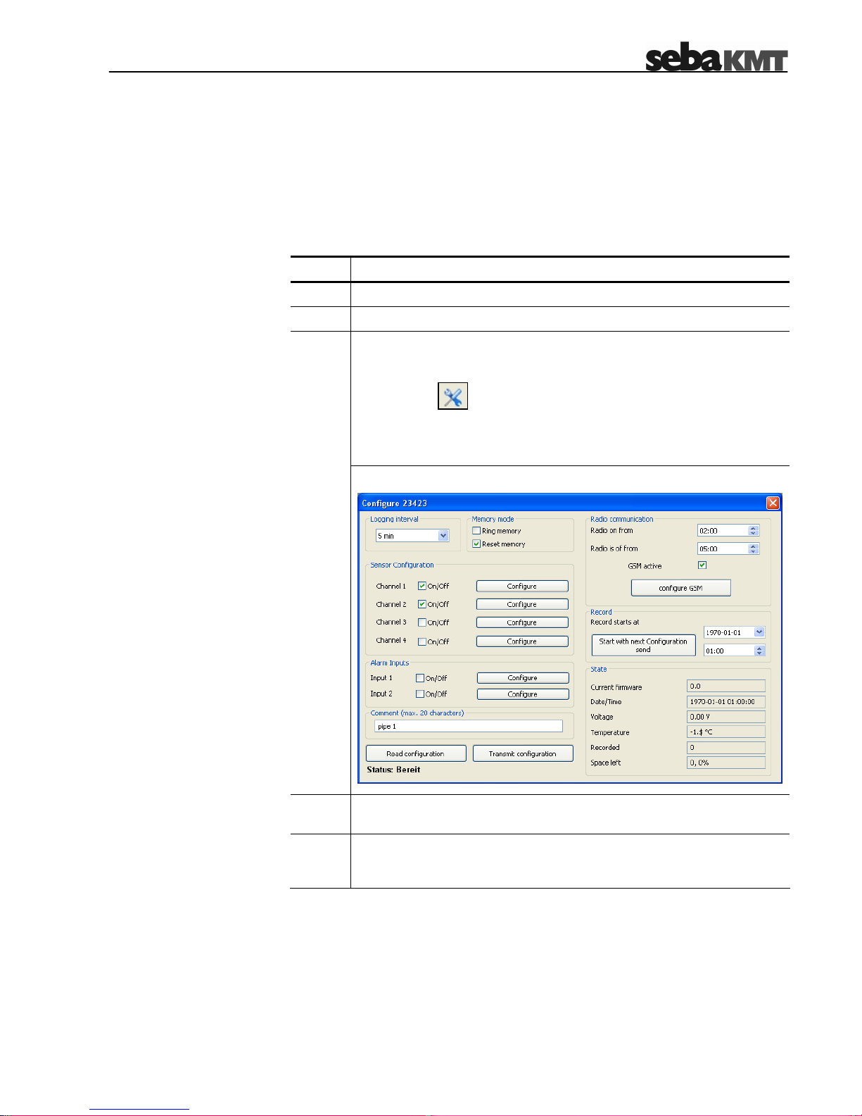
Preparation Proceed as follows to access the configuration of a specific logger:
Step Action
1
Make sure the logger is connected to the PC and switched on.
2
Select the logger you want to configure in the logger tree.
Proceed in one of the following ways:
o Select Logger -> Configuration from the menu bar.
o Select from the toolbar.
o Right-click on the logger in the logger tree and select
Configuration from the context menu.
3
Result: The following window appears:
4
Read out the effective configuration from the logger using the
Read configuration button.
5
Configure the logger as described in the following sections and,
afterwards, transmit the new configuration data to the device as
described in section 5.8.
Page 36
5-36
5.1 Selecting the Logging Interval
You can select the time interval in which the measured values are logged from the
Logging interval drop-down list.
5.2 Sensor Configuration
Depending on its configuration, up to 4 sensors can be connected to a logger. In
order to evaluate the logged data in the right way, the logger needs to know which
type of sensor is connected to which channel.
Introduction
• Make sure that the sensor configuration is consistent with the effective
connection setup. Each channel is linked with specific wires of the
VK 75/76 connection cables. For a detailed description, please refer to
section 3.3.1.
• Please pay regard to the fixed channel allocations when configuring
internal pressure sensors or sensors with current output (see section
3.3.1.1).
• Make sure you enter the values in the same format as shown in the figures.
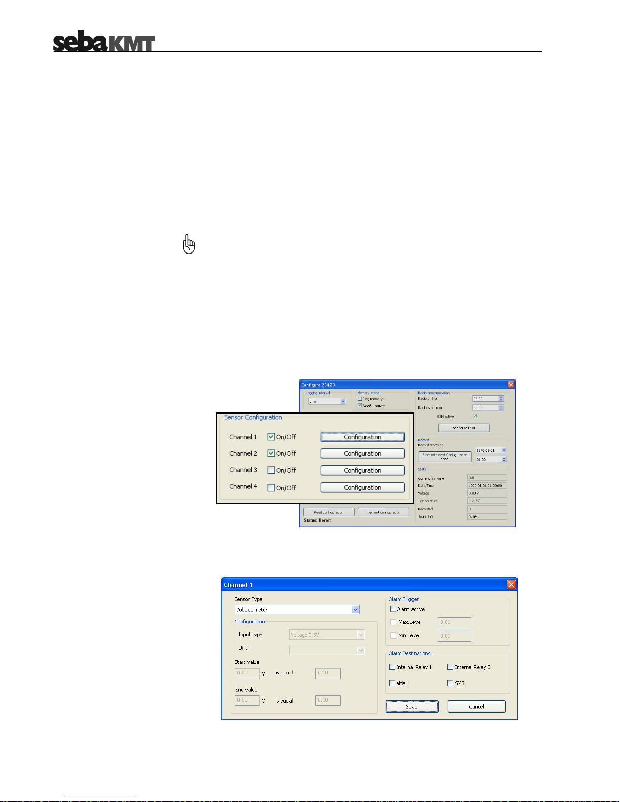
Activating channels First of all, you have to specify which channels are in use (connected to a sensor)
during the upcoming operation period. A channel can be activated by marking the
respective On/Off checkbox exemplified by the following figure:
Configuring a channel After a channel has been activated, it has to be specified which type of sensor is
connected to the channel. Click the respective Configuration button. The following
window appears:
Page 37

5-37
5.2.1 Sensor Type
Selecting the sensor type Select the sensor connected to the channel from the drop-down list. The sensors
contained in this list are parameterized and no further configuration is required. The
internal pressure sensors (Seba Standard Pressure) of the Sebalog D are also part
of this list. The measuring range of the internal pressure senor can be obtained from
the type number of the logger (see section 2.3). If the sensor type is not contained in
the drop-down list, the customer specific entry has to be selected.
5.2.1.1 Configuring a „Customer Specific“ Sensor
Introduction The physical value measured by the sensor is transformed into an electrical signal
(e.g. voltage, pulses, frequency) which is used to transmit the data to the logger. In
order to transform this carrier signal back into the original physical values, the logger
needs to know how the ranges are correlated to each other.
If a predefined sensor from the drop-down list has been selected, these parameters
have been automatically populated.
However, in the case of a customer-specific sensor, the input type (carrier) and the
unit of the physical value have to be specified manually. Furthermore, the upper and
lower thresholds of the input signal and the correlating measurement values have to
be specified.
Configuring the input type Perform the following steps to configure the input type of a customer-specific sensor:
Step Action
1
Select the type of signal, the sensor uses to pass the measured data to
the logger from the Input type drop-down list.
2
Select the unit of the physical value measured by the sensor from the
Unit drop-down list.
Depending on the selected input type and value, some additional fields
may need to be populated with the upper and lower thresholds of the
input signal and the correlating measurement values.
3
For detailed information about the input type and the ranges, please
refer to the manual of the connected sensor.
Correlating measured values
Input signal thresholds
Page 38

5-38
5.2.1.2 Input Type Examples
Input type Voltage
A 10 bar pressure sensor with voltage output is connected to a channel of the
logger.
Input type: Voltage 0-5V
Unit: bar
The lower limit of the measuring range (0 bar) is indicated by a voltage value of 0 V
while the upper limit (10 bar) correlates with 5 V. As a result, the fields must be
populated as follows:
The maximum permissable input voltage is 5 V. Higher input voltages may
damage the device.
Input type Frequency
A level meter with frequency output is installed in a 430 l tank.
Input type: Frequency
Unit: l
The maximum level of 430 l is indicated by a frequency of 1000 Hz. As a result, the
fields must be populated as follows:
The maximum permissable frequency is 1000 Hz. If the connected sensor
transmits higher frequencies, a frequency divider must be interconnected.
Page 39

5-39
Input type Pulse
A flowmeter with a di
gital pulse output is connected to a channel of the logger. The
flowmeter transmits one pulse per 16 litre.
input type: Pulse
Unit: l
The flow can be measured per hour or per second. If per hour is selected, the
logging interval must be higher than 15 minutes. Otherwise, an error message
appears.
Determining the leading
sign for another channel
A flowmeter is connected to channel 2. In addition to the flow rate itself, the flow
direction shall be determined. For this purpose, a sensor which indicates the flow
direction by means of voltage values is connected to another channel of the logger.
Input type: Sign slave for other channel
First of all, it has to be specified which direction is indicated by the 5 V value. A
voltage value of 0 V automatically indicates the opposite direction. Furthermore, the
channel (flow), the determined flow direction applies to, has to be selected (in this
case Channel 2).
Page 40

5-40
5.2.2 Configuring Alarm Conditions (Threshold Monitoring)
Introduction The Sebalog D can trigger an alarm whenever a specified minimum or maximum
threshold is crossed.
That way, up to two connected devices (e.g. a pump or a valve) can be triggered by
the internal relays.
Furthermore, alarm messages can be sent via SMS or email, if GSM connectivity
has been established and properly configured (see sections 3.2 and 5.4).
The alarm thresholds must be individually specified for each channel.
Configuring alarms Perform the following steps to configure the alarm thresholds and the alarm
destinations:
Steps Action
1 Activate the Alarm active checkbox in order to enable alarming for this
channel.
2
Specify whether there is a minimum and / or a maximum threshold to be
monitored by activating the respective checkbox(es).
3
Enter the minimum and / or the maximum threshold into the respective
field(s).
Specify under Alarm Destinations which of the relays shall switch in the
case of an alarm and which type of alarm message shall be sent.
4
The internal relay of single-channel loggers (LOG D-1) is always
Relay 2!
Page 41

5-41
When a maximum threshold is exceeded, the device connected to the internal relay
is switched on. The device is switched off as soon as the measured value falls below
the threshold again. This applies for the lower threshold the other way around.
A relay cannot be assigned to more than one alarm. If a relay is already
included in an existing channel configuration, it cannot be used in combination
with any other channel or switching input (see section 5.3).
5.2.3 Finishing the Configuration
Confirm and save the configuration of a channel by clicking the Save button.
Perform the configuration for the remaining channels.
Page 42
5-42
5.3 Configuring the Switching Inputs (Alarm Inputs)
Introduction Depending on its configuration a logger can be equipped with up to two switching
inputs (alarm inputs) which can be connected to active circuits. For each of these
inputs, it can be specified which input voltage value causes an alarm. An example of
such an alarm loop is shown in section 3.3.1.4.
As known from the channel configuration, an alarm can trigger up to two internal
relays.
Furthermore, alarm messages can be sent via SMS or email, if GSM connectivity
has been established and properly configured (see sections 3.2 and 5.4).
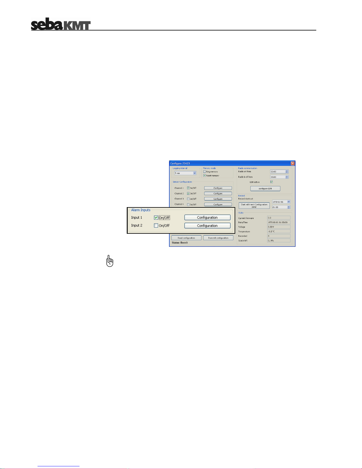
First of all, you have to activate the Alarm inputs which are going to be part of an
alarm input during the upcoming operation period by marking the respective On/Off
checkbox:
Activating an
alarm input
The switching input of single-channel loggers (LOG D-1) is always Input 2!
Page 43

5-43
Configuring an
alarm input
After an alarm input has been activated, it must be specified which input voltage
value causes an alarm and which actions are triggered by an alarm. Click the
respective Configuration button. The following window appears:
Proceed as follows to configure an alarm input:
Step Action
1
Specify the input voltage value which does, when present at the
switching input, trigger an alarm.
The input voltage threshold is 2.5 V. Any voltage value below 2.5 V is
interpreted as 0 V while voltages higher than 2.5 V are interpreted as
5 V. In order to ensure a reliable classification, the actual voltage values
should not be too close to 2.5 V.
2 Specify under Alarm Destinations which of the relays shall switch in
the case of an alarm and which type of alarm message shall be sent.
3 Confirm and save the settings by clicking the Save button.
The internal relay of single-channel loggers (LOG D-1) is always Relay 2!
A relay cannot be assigned to more than one alarm. If a relay has been already
assigned to a switching input, it can neither be assigned to the other switching
input nor be used for threshold monitoring (see section 5.2.2).
Page 44

5-44
5.4 Configuring the Radio Communication
Configuring a timeframe
for radio communication
Data transfer between logger and PC can be performed via radio connection using
the E-Box (see section 4.3.1). If radio communication is going to be established
during a specific timeframe only (e.g. during daytime), the range of this timeframe
has to be specified via the Radio on from and Radio is off from fields. Out of this
timeframe, the logger is not accessible via radio interface. That way, energyintensive changes from energy saving mode to data transfer mode can be avoided.
If the same time value is entered in both fields, radio access is not restricted.
Page 45

5-45
If the logger is equipped with a GSM modem, the logger can be used for alarm
messaging via email and SMS. Furthermore, periodical data transfer to a FTP server
can be set up.
For this purpose, a GPRS-enabled SIM card (data contract) is required which can be
obtained from almost any local mobile network operator.
Configuring the
GSM settings
Usually, all the data required to set up mobile data transfer is provided within the
contract. Further information can be obtained from the website or the hotline of
the mobile network operator. If necessary, request guidance for setting up data
communication in particular. SebaKMT cannot provide any specific technical
advice in this case.
Proceed as follows to set up data communication via GPRS:
Step Action
1
Make sure the logger has been properly prepared for GSM connectivity
(see section 3.2).
2 Activate the GSM active checkbox in order to enable the GSM
functionality.
Click the configure GSM button. 3
Result: The following window appears:
4
Configure the interface settings as described in the following sections.
Page 46

5-46
5.4.1 SIM Card Configuration
Enter the phone number and the PIN code of the SIM card into the respective
fields. These numbers are an essential part of the contract data.
5.4.2 Configuring the Internet Access Point of the Network Operator
Populate the fields under Internet configuration with the access point data
provided by your mobile network operator. Normally, this information can be taken
from the contract data. Otherwise, contact your mobile network operator.
If your operator is contained in the Templates drop-down-list, the data is
automatically filled in.
5.4.3 Email Configuration
Perform the following steps, if you want to enable alarm messaging via email:
Step Action
1 Enter the SMTP server address (SMTP), User and Password of the
account used for email transmission into the respective fields.
If the mail server of your company is not capable for this task (e.g. due
to a firewall), a webmail account from an internet service provider
(e.g. Yahoo or Google) can be used instead, if its SMTP settings are
known. Usually, this kind of information can be obtained from the “How
to configure an email client” tutorial on the providers’ website.
Username and password can be specified during the account setup
procedure or can be requested from your system administrator.
SebaKMT does not provide email accounts.
2 Enter a sender email address into the Name field. This address should
clearly indicate the logger, the email has been sent from
(e.g. Logger815@group2.de). This makes it easier to localize where the
alarm has been raised.
3
Enter the recipient address, the alarm message shall be send to, into
the eMail field.
4
Optionally, enter another recipient address, receiving a copy of the
alarm message, into the eMail CC field.
Page 47

5-47
5.4.4 FTP Settings
If you want the logged data to be transferred to a FTP server at regular intervals, you
have to specify the server settings. You can ask your administrator to set up a FTP
server using the server infrastructure of your company or you can rent a server from
an ISP. In the latter case, all required information (server address, port, username
and password) have to be obtained from the service provider.
In order to activate the FTP transfer, please check the activated checkbox under
FTP Settings and populate the fields with the data of your FTP server.
After the server has been activated and configured, a data transfer takes place each
day or after 500 data sets have been collected respectively.
A logd folder must be created on the FTP server. Furthermore, a subfolder
named similar to the logger ID (plus two leading zeros) must be created inside
this folder.
Example: In order to enable FTP data transfer for a logger with the ID 000815,
the …/logd/00000815 folder must be crated on the FTP server.
5.4.5 SMS Destinations
You can specify up to three mobile numbers where alarm messages via SMS shall
be sent to under SMS destination.
5.4.6 Summary Messages
Under Summary you can specify whether or not a summary message containing the
highest and lowest measured values of the day or week shall be sent to all mobile
numbers / email addresses stored in the database. To do so, please proceed as
follows:
Step Action
1
Check the respective checkbox in order to activate a summary message
via SMS and / or email, whereupon new fields are activated.
2 Specify whether a daily or weekly summary message shall be sent by
checking the respective checkbox.
3
Specify the point in time and, if required, the day of the week, the
message shall be sent.
Make sure to enter the values in proper format. Time values are specified in
24-hour format.
Page 48

5-48
5.4.7 Testing the GSM Settings
You can send a test email or a test SMS in order to check whether a GSM
connection can be established with the active settings. Furthermore, the FTP settings
can be tested by creating a file to the respective FTP folder.
The GSM configuration must have been already finished (see previous
sections) and the settings must have been transferred to the logger before a
test can be performed (see section 5.8).
5.4.7.1 Testing SMS / Email Transmission
Perform the following steps to send a test SMS / email:
Step Action
Click on the Test GSM settings button. 1
Result: A new window appears
Click on the Send Test SMS button or the Send Test eMail button in
order to send a test SMS or email respectively. During transmission, the
I/O control lamp is lit orange.
2
Result: If the transmission has been successfully completed, all
addressees should receive a SMS or email of the following layout:
2
LOG D; ID 00815
(comment):
18.03.2008
12:44:27
SignalQ: 13
NetWorkReg: 1
Identification number of the logger
Date and time of the test
Signal quality
Network registration status
Page 49

5-49
(Continuation from previous page:)
Step Action
If no SMS or email has been received, the logger probably failed to
establish a GSM connection.
Click on the Read GSM log button in order to identify possible sources
of the problem. A message of the following layout appears in the display
area:
3
The comment behind the error code can be a good indication of the
source of the problem. In the case of a PIN ERROR, e.g., you should
check the SIM card configuration (see section 5.4.1).
In the case of bad signal quality (SignalQ 0 or 1), it may help to move
the GSM antenna in a better position (see section 3.5).
If the network registration has failed, use a mobile phone to check
whether the SIM card works.
GSM LOG:
12:44:27 18.03.2008
Code 14, PIN Error
SignalQ: 0 Bad
Net: 0 Not registered,
search stopped
Signal quality: 0-1 … bad
2-15 … average
16-30 … good
Error code with comment
Date and time of the test
Network registration status:
0 … „not registered, search stopped“ 4 … “unknown”
1 … „registered, home network” 5 … “registered, roaming”
2 … “not registered, searching…” default … “unknown code”
3 … “registration denied!”
Page 50

5-50
5.4.7.2 Testing FTP Data Transfer
Perform the following steps to check the FTP settings:
Step Action
Click on the Test GSM settings button. 1
Result: A new window appears.
Click on the Send Test FTP data button. Thereupon, the logger tries to
create a test file inside the respective folder on the FTP server. During
the test procedure, the I/O control lamp is lit orange.
2
Result: If a file has been created in the folder, the test was successful.
3
If no file has been created, the logger probably failed to establish a GSM
connection or was not able to establish a connection to the server. Click
on the Read GSM log button in order to identify possible sources of the
problem (see step 3 of previous section). Do also check the FTP
settings.
5.4.8 Finishing the Communication Setup
Close and save the communication settings by clicking on the Save button.
5.5 Start Time
The point in time, the logger starts logging, has to be defined under Record.
You can specify a point in time using the controls. If you click on the Start with next
Configuration send button, logging starts right after the configuration has been
transmitted to the logger.
2
Page 51

5-51
5.6 Memory Mode
The logger has 2 MB internal memory. By default, the device stops logging as soon
as the memory is full.
By checking the Ring memory checkbox, the logger can be set to ‘ring buffer’ mode.
As the memory fills up with data in this mode, the device keeps logging and the
respective oldest value is overwritten.
By checking the Reset memory checkbox, the memory is cleared. Afterwards, you
have to confirm the deletion of the data. The memory is cleared as soon as the
configuration is transmitted to the logger.
5.7 State
Some characteristic data about the logger are listed under State. The data has been
derived during the last data or configuration readout. Amongst others, the remaining
memory in percent and the supply voltage are indicated.
If EXT is displayed instead of an actual voltage value, the logger is connected to an
external power supply.
5.8 Finishing the Configuration
Adding a comment
By adding a comment to the Comment field you can take some notes, e.g., on the
location of the logger.
Transmitting the
configuration data
Click on the Transmit configuration button in order to finalize the configuration
and to store the settings on the logger. Thereupon, the data is transmitted to the
logger.
After the settings have been saved on the device, a confirmation message appears.
If no connection to the logger can be established, an error message appears.
Check the link between logger and PC (see section 4.3) and try to transmit the data
again.
Page 52

6-52
6 Retrieving and Evaluating Data
6.1 Retrieving Data from the Logger
The data can be readout via cable connection (see section 4.3.2) or radio link (see
section 4.3.1). Proceed as follows, to readout the data from the logger:
Step Action
1
Make sure, the logger is connected to your PC (either via USB cable or
via E-Box).
2
Mark the logger, you want to collect the data from, in the logger tree.
Proceed in one of the following ways:
o Select from the toolbar.
o Right-click on the logger in the logger tree and select Read data
from the context menu.
3
Result: A new window appears.
4
If you would like to receive only these data sets which are not already
contained in the local database, check the Read only new data
checkbox. Otherwise, all data stored on the logger is transmitted which
may considerably increase the transmission time, if the logger is
connected via radio link.
5 Click on the Read data using EBox / USB cable button to readout the
data from the logger.
A progress bar indicates the progress of the transmission.
6 After the data transfer has been finished, click on the Open button. A
new window appears and the data is presented in a diagram.
You can evaluate the data and change the way the data is represented
in the diagram using the functions described in section 6.3.
Page 53

6-53
6.2 Collecting Data from the FTP Server
If the logger is equipped with a GSM modem, the logged data can be automatically
transmitted to a FTP server (see section 5.4.4). You can access a FTP server from
any PC with an internet connection.
Proceed as follows to download the data from the FTP server:
Step Action
1 Select Program Settings -> Settings from the menu bar and enter
server address, username and password into the respective fields under
FTP settings. Confirm the settings by clicking the Save button.
2
Mark the logger, you want to collect the data from, in the logger tree.
Proceed in one of the following ways:
o Select from the toolbar.
o Right-click on the logger in the logger tree and select Read data
from the context menu.
3
Result: A new window appears.
4
If you would like to receive only these data sets which are not already
contained in the local database, check the Read only new data
checkbox. Since, in most cases, the data is downloaded via broadband
connection, this option does not affect the transfer time.
5 Click on the Read data from FTP server button to download the data
from the FTP server.
A progress bar indicates the progress of the transmission.
6 After the data transfer has been finished, click on the Open button. A
new window appears and the data is presented in a diagram.
You can evaluate the data and change the way the data is represented
in the diagram using the functions described in section 6.3.
Page 54

6-54
6.3 Evaluating Measured Data
Displaying the
measured data
After the measured data has been retrieved from the logger (see section 6.1), the
progression of the measured values can be illustrated in a diagram and, by this
means, can be easily evaluated.
Proceed as follows to display the data of a specific logger:
Step Action
1
Mark the logger whose data you want to display in the logger tree.
Proceed in one of the following ways:
o Select Logger -> Display data from the menu bar.
o Right-click on the logger in the logger tree and select Display
data from the context menu.
2
Result: The following window appears:
Diagram The curves of the different channels share in one diagram. The X-axis represents the
timeline while the Y-axis represents the measured values.
By clicking on a curve, the channel is selected and the curve is shifted to the
foreground.
By double-clicking the diagram, the diagram properties can be changed.
Info bar If you click on a channel in the blue info bar at the top right of the window, the
respective curve is shifted to the foreground and some characteristics of the channel
are displayed in the info bar.
The values shown in the info bar result only from the visible part of the curve. Any
maximum or minimum values outside of the current visible time range are not
considered.
By selecting a channel / curve, the unit of the Y-axis is adapted to the respective
measurement. However, the scaling does not change.
Page 55

6-55
Navigating through the
measured values
You can use the navigation panel at the lower right of the window to navigate:
Arrow keys Scrolling along the axes
Magnifier Zooming in and out
In addition you can use the mouse wheel for navigation (you have to click on the
diagram first):
Mouse wheel Scrolling along the X-axis
Shift-key + mouse wheel Scrolling along the Y-axis
CTRL-key + mouse wheel Zooming the Y-axis in and out
If you right-click on the diagram, you can access a few more navigation tools from
the context menu:
Magnify This tool can be used to magnify a specific area of the diagram. After
the menu item has been selected, the cursor changes to . Click
on one corner of the area you want to select and hold down the mouse
button. Afterwards, select the area and release the mouse button.
Move This tool can be used to freely move the curves within the diagram.
After the menu item has been selected, the cursor changes to .
Click on the diagram, hold down the mouse button and move the
mouse in any direction in order to move the curves within the
diagram.
Choose By selecting this item you can leave the Move or Magnify modes
described above.
Reset By selecting this menu item, the default view is restored.
Print By selecting this menu item, the current diagram view can be
printed. It is recommended to use landscape format for printing.
Properties By selecting this menu item, a few diagram properties (e.g.
background colour and grid style) can be changed.
By clicking the middle of the navigation panel, the default view can be restored.
Placing guides In order to accurately read off measured values or time values, you are allowed to
place any amount of guides on the diagram. First, click on an axis (Y-Axis for
horizontal guides; X-Axis for vertical guides). Then, click on a certain point within the
diagram (e.g. on a curve). The measured value or the time value can now be read off
at the axis intersection.
Guides can be moved by left-clicking on them and holding down the mouse button
while moving the mouse in any direction. A guide can be deleted by right-clicking on
it.
Page 56
7-56
7 Miscellaneous Functions
7.1 Identifying Loggers
This function can be used to identify all loggers within the radio range of the E-Box
(see also section 4.3.1). The function can be also used to identify a logger connected
via USB interface.
Proceed in one of the following ways to access this function:
o Select Logger -> Identify from the menu bar.
o Select
from the toolbar.
A new window appears displaying the IDs of all loggers which could be found.
7.2 Real-Time Measurement
Proceed as follows to retrieve and display values of all channels in real-time:
Step Action
1
Make sure, the logger is connected to your PC (either via USB cable or
via E-Box) and that the logger is switched on.
2
Mark the logger in the logger tree.
Proceed in one of the following ways:
o Select Logger -> Real time measurement from the menu bar.
o Select from the toolbar.
o Right-click on the logger in the logger tree and select Real time
measurement from the context menu.
3
Result: A new window appears displaying the present measured value
for each active channel in real-time.
Page 57

7-57
7.3 Setting the Clock
In order to make the measurement results comparable over time, the loggers must
be time-synchronous. For this purpose, the internal clock of all loggers within the
radio range of the E-Box can be adjusted to the system time. This also works if only
one logger is connected to the PC via USB interface.
Proceed in one of the following ways to access this function:
o Select Logger -> Set clock from the menu bar.
o Select from the toolbar.
o Right-click on the logger in the logger tree and select Set clock from the
context menu.
7.4 CSV Export
The data collected from a logger can be exported in CSV (Comma Separated
Values) format. In doing so, a CSV file containing all logged value-time pairs line by
line is saved to the hard disk. Proceed as follows:
Step Action
1
Mark the logger whose data you want to export in the logger tree.
Proceed in one of the following ways:
o Select Logger -> Export CSV from the menu bar.
o Right-click on the logger in the logger tree and select Export
CSV from the context menu.
2
Result: An explorer window appears.
Browse to the folder where you want to save the CSV file and click
Open.
3
Result: The file is saved to the selected folder and can be viewed on
the PC using any CSV-capable application (e.g. Excel).
7.5 Deleting Logged Data
Proceed as follows to delete data which has been already exported in CSV format or
is not needed anymore:
Step Action
1
Mark the logger whose data you want to delete in the logger tree.
2 Right-click on the logger in the logger tree and select Clear from the
context menu.
3 Click Ok in order to clear the data from the database.
Page 58

7-58
7.6 Firmware
Checking the firmware
version
Proceed as follows to check the current firmware version of a logger:
Step Action
1
Make sure, the logger is connected to your PC (either via USB cable or
via E-Box) and that the logger is switched on.
2 Select Program Settings -> Firmware Update from the menu bar.
3
Enter the ID of the logger.
Click on the Show logger version button to query the firmware version
from the logger.
4
Result: The current firmware version is displayed.
Updating the firmware Please check our website www.sebakmt.com frequently for an updated Sebalog D
firmware version. If a newer version is available, save the file to your hard disk and
proceed as follows to update the firmware of the logger:
Step Action
1
Make sure, the logger is connected to your PC (either via USB cable or
via E-Box) and that the logger is switched on.
2 Select Program Settings -> Firmware Update from the menu bar.
3
Enter the ID of the logger.
4 Click on the start update button.
Browse to the location of the firmware file select the file and click Open.
Afterwards, the file is transferred to the logger.
Only update with firmware provided by SebaKMT. If you use other
files, the device will not start and it will have to be repaired by
SebaKMT Service.
Do not switch off the device during the update. If you do, the device
will have to be repaired by SebaKMT Service.
5
Result: After the update has been finished, a notification window
appears and the logger switches off.
6
Switch on the logger again and establish a connection to the PC.
7
Check whether the new firmware version has been successfully
installed on the logger (see above).
Page 59
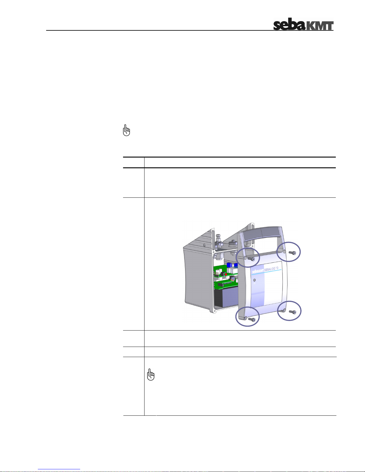
8-59
8 Replacing the Batteries
The internal lithium batteries of the Sebalog D are able to supply a constant voltage
level over a long period. Under ideal conditions, a logger can be operated for up to
five years without changing the batteries. The voltage level can be read off from the
Voltage parameter in the logger configuration window (see section 5.7).
Empty batteries can not be recharged but can be single-handedly replaced by
batteries of the same type.
Introduction
A total protection against water and dust ingress compliant with IP 68 can only
be warranted, if the battery replacement is carried out by SebaKMT or an
authorized service station.
Replacing the batteries Proceed as follows to replace the batteries:
Step Action
1
In order to replace the lithium batteries of the Sebalog D, a special battery
replacement set which contains all required cables and plugs and a new
front panel has to be ordered from SebaKMT. Such a set is not available
in stores.
2
Loosen the four marked screws with a M3 allen key or with a crosstip
screwdriver respectively (depending on the logger type) and remove the
front panel.
3
Keep in mind how the batteries are connected before you disconnect and
remove the old batteries.
4
Insert the new batteries and restore the connections.
Attach the front panel to the housing again.
5
In order to ensure the total protection against water and dust ingress
compliant with IP 68, the following instructions must be observed:
• The rubber seal and the contact surfaces of the housing must be
free of dirt.
• Be careful not to jam the housing parts against each other.
• Tighten the screws with a torque of 1 Nm.
 Loading...