

Page 1

Operating instruction
Hydrolux® Leak locator
HLE 500
Produktbild wie in den Prospekten ohne Rahmen
Ansprechpartner Frau Badziura
HLE 5000
Version 1.0
Mess- und Ortungstechnik
Measuring and Locating Technologies
Elektrizitätsnetze
Power Networks
Kommunikationsnetze
Communication Networks
Rohrleitungsnetze
Water Networks
Leitungsortung
Line Locating
Edition: 02 (2005/02)
Page 2

Operating instructions HLE 500/5000
II
MAN_HLE500_HLE5000_eng_02
Page 3
Operating instructions HLE 500/5000
III
Quality certificate
The quality control system used by Seba Dynatronic® and
sebatel® meet the highest requirements of the
international quality standard DIN ISO 9001 and the
European standard EN 29001. This quality system was
approved by the German Association for the Certification
of Quality Systems with the numbers EN 19677 and DQS
19677-01.
How do you contact us?
SebaKMT
Mess- und Ortungstechnik GmbH
Dr.-Herbert-Iann-Str. 6
96148 Baunach, Germany
Telephone: +49 (0) 9544 680
Fax: +49 (0) 9544 2273
Email: sales@sebakmt.com
MAN_HLE500_HLE5000_eng_02
Internet: www.sebakmt.com
Page 4

Operating instructions HLE 500/5000
IV
MAN_HLE500_HLE5000_eng_02
Page 5
Operating instructions HLE 500/5000
V
Table of contents
1 Description 1
1.1 General 1
1.2 Construction 2
1.3 Technical data 2
1.4 Delivery includes 3
1.4.1 5000/500 equipment 3
1.4.2 Selectable microphone sets 3
1.4.3 Optional accessories 4
2 Getting to know the HLE 5000/500 5
2.1 HLE 5000/500 controls 5
2.2 Connections at the side 5
2.3 Battery chamber 6
2.4 Automatic battery monitoring 7
2.5 Illumination of the LCD display 7
2.6 Microphones 7
2.6.1 PAM W-1 8
2.6.2 PAM U 9
2.7 Headphones 10
3 Practical work 11
3.1 Headphones and microphone connection 11
3.2 Switching on
3.3 Volume and amplification 12
3.3.1 Setting the volume 12
3.3.2 Setting the gain 13
3.4 The amplification display 13
3.5 Filter setting (only HLE5000) 14
3.5.1 Adjusting the cut-off frequencies 14
3.6 Filter selection in practice 15
3.6.1 Filter selection A (Ground microphone PAM W-1, PAM U with 3-point
foot) 16
3.6.2 Filter selection B: Sensor rod (Pam U with spike) 16
3.7 Mute button
3.8 The histogram 16
3.9 Long-term measurement (HLE 5000 only) 18
3.10 Location of pipes using the RSP-3 or PWG (HLE 5000 only) 19
3.11 Switching off
11
X
16
19
4 Faults 20
4.1 Can't switch on 20
4.2 Battery monitor does not react 20
4.3 No sound can be heard 20
4.4 Scratching sounds in the headphones 20
MAN_HLE500_HLE5000_eng_02
Page 6

Operating instructions HLE 500/5000
VI
List of illustrations
Fig 1 : HLE 5000/500 control panel...................................................5
Fig 2 : Side view left and right with connections................................6
Fig 3 : Base plate with locking screws...............................................7
Fig 4 : PAM U with sensor rod...........................................................9
Fig 5 : PAM U with magnet................................................................9
Fig 6 : PAM U with 3-point foot........................................................10
Fig 7 : Start image with version number..........................................11
Fig 8 : Opening menu after switch-on..............................................12
Fig 9 : Setting the volume................................................................12
Fig 10 : Setting the gain.....................................................................13
Fig 11 : Current and minimum value .................................................14
Fig 12 : Filter settings........................................................................14
Fig 13 : Adjusting the lower filter cut-off frequency............................15
Fig 14 : Adjusting the upper filter cut-off frequency...........................15
Fig 15 : Dual segment analysis (DSA)...............................................17
Fig 16 : Histogram measurement ......................................................17
Fig 17 : Long-term measurement ......................................................18
MAN_HLE500_HLE5000_eng_02
Page 7

Operating instructions HLE 500/5000
1 Description
1.1 General
The new HLE 5000/500 leak locator comprehensively deals
with finding leaks in pipe networks for the supply of drinking
water. The equipment can of course be used on other pipe
systems, provided that the liquid comes out of the pipe under
pressure and that the resulting noise carries to the surface of
the ground. With the HLE 5000/500 it is possible to both prelocate and to pinpoint the location of the fault. With a special
Dual Segment Analysis (DSA) display, both the minimum
value of the constant noise as well as the leak noise can be
recognised. With the “Mute” option, used when moving the
ground microphone, a new minimum display results. A
comparison of the measured values is thus always possible.
In the “HISTOGRAM” function, each measurement location is
stored, one by one.
This equipment is the first instance where computer
supported reduction of extraneous noise is used, where
impulse type disturbances are acoustically suppressed.
Preferably, only constant noise (as produced by a leaking
pipe) is displayed as a minimum value.
When locating plastic pipes with the assistance of an RSP3
“pipe pecker”, picking up impulses is then desirable and
improves the results. For this reason, the HLE 5000 has a
special pipe location mode that is activated, after switching
on, by pressing the symbol button.
Another important function of the HLE 5000 is the noise level
recording with which the course of the development of the
noise is shown on the LCD display as a graph over time.
1
MAN_HLE500_HLE5000_eng_02
Page 8

Operating instructions HLE 500/5000
1.2 Construction
The leak location equipment is in a splash-proof housing
made of robust plastic. The few control buttons are so
arranged that they can also be operated wearing gloves. The
display is equipped with backlighting. That means that work is
also possible under poor lighting conditions, or at night.
The batteries required to supply the power are housed in the
base of the equipment behind a cover which is easy to open
to quickly exchange the batteries. The connections for the
microphone and headphones are on the two sides of the
equipment and can be quickly plugged in or removed.
2
1.3 Technical data
Analysis bandwidth: 0 Hz – 4000 Hz
Filter cut-off frequencies: 0 - 70 Hz, 106 Hz, 160 Hz,
Histogram recordings: 9 dual displays
Storage of noise levels: 3 – 10 – 30 min
Display 130 x 36 mm: LCD display
LCD illumination: available
Power supply 1:
Power supply 2 (option):
Operating time: > 35 h (battery),
Storage: 9 measurements
Mute button: available
Operating temperature: -10 to +50 °C
Storage temperature: -10 to +70 °C
Protection class when in
operation:
Dimensions (L x W x D): 215 x 95 x 110 mm
Weight: HLE 5000
Weight: PAM W-1
Weight: PAM U
240 Hz, 360 Hz, 540 Hz,
800 Hz, 1200 Hz, 1800 –
4000 Hz
10 x AA batteries, (1.5 Volt)
12 x rechargeable batteries
(1.2 Volt)
> 15 h (rechargeable battery)
IP 54
1200 g (with batteries)
3.5 kg (with carrying pole)
500 g
MAN_HLE500_HLE5000_eng_02
Page 9

Operating instructions HLE 500/5000
1.4 Delivery includes
1.4.1 5000/500 equipment
Leak location equipment with batteries HLE 5000 or HLE 500
Headphones
(extraneous noises filtered)
Carrying strap
Case HLK
Operating instructions BED HLE 5000
1.4.2 Selectable microphone sets
Professional set consisting of:
Piezo ground microphone
(with wind shield)
Connection cable to PAM W-1 VK65
3-point foot adapter PAM W-1D
Carrying pole for PAM W-1
Universal PAM U microphone PAM U
Magnetic adapter
Sensor rod
3-point foot for PAM U PAM U-D
Extension rod VST T-1
Ground microphone (with wind shield) consisting of:
Piezo ground microphone
(with wind shield)
Connection cable to PAM W-1 VK65
3-point foot adapter PAM W-1D
Carrying pole for PAM W-1
Ground microphone
Piezo ground microphone PAM B-1
Connection cable to PAM W-1 VK65
Carrying pole for PAM B-1
Universal microphone
Universal microphone PAM U
Magnetic adapter
Sensor rod
3-point foot adapter for PAM U PAM U-D
KR 2
PAM W-1
PAM W-1
3
MAN_HLE500_HLE5000_eng_02
Page 10

Operating instructions HLE 500/5000
1.4.3 Optional accessories
4
Radio module for wireless
transmission between microphone
and amplifier
Sensor rod extension VST T-1
Special headphones
(highly insulated from extraneous
noise)
Sliding adapter 42 mm AD S-42
Sliding adapter 20 mm AD S-20
Magnetic adapter
PAM 868
KM2
MAN_HLE500_HLE5000_eng_02
Page 11

Operating instructions HLE 500/5000
I/O
HYDROLUX
®
with backlight
2 Getting to know the HLE 5000/500
Before putting the equipment into operation, you should get
to know all of the controls, the devices which can be
connected and the power supply.
2.1 HLE 5000/500 controls
5
ON/OFF/
backlight
button
Mute button
2.2 Connections at the side
LCD display
X
Fig 1 : HLE 5000/500 control panel
Volume
control
Soft keys
The sockets for the microphone and the headphones are on
the two sides of the equipment. The connections are shown
in fig 2.
MAN_HLE500_HLE5000_eng_02
Page 12

Operating instructions HLE 500/5000
connection
6
Headphones
connection
2.3 Battery chamber
Microphone
Fig 2 : Side view left and right with connections
The sockets are only suitable for headphones and
microphones from SebaKMT. Connecting other headphones
or microphones can lead to equipment failure or damage to
the HLE 5000/500.
After opening the base flap (fig. 3) the battery chamber is
accessible. When fitting the batteries make sure that the
polarity is correct.
MAN_HLE500_HLE5000_eng_02
Page 13

Operating instructions HLE 500/5000
Locking screws
Fig 3 : Base plate with locking screws
2.4 Automatic battery monitoring
7
When working with the leak detection equipment, the state of
the batteries is monitored continuously. Should the battery
voltage drop too far, this will be indicated by a flashing
battery symbol in the top right of the display.
From that point, there is about 4 hours of battery life
remaining.
When you have to change the batteries, change all
10 batteries at one time!
2.5 Illumination of the LCD display
By briefly pushing the on/off button
equipment is turned on, the illumination for the display will be
activated / deactivated.
2.6 Microphones
The microphones are connected to the leak location
equipment via a cable. The socket for this connection is on
the right hand side of the equipment (see fig. 2). To record
the sound of leaks there are various sensors/ground
microphones available. A sensor rod microphone is used to
listen to sounds from directly accessible pipe parts, such as
hydrants or valves. Each sensor is used as follows:
when the
MAN_HLE500_HLE5000_eng_02
Page 14

Operating instructions HLE 500/5000
2.6.1 PAM W-1
The PAM W-1 is an active piezo ground
microphone for roads and hard ground
coverings. The microphone is particularly well
shielded from the wind, using a bell-shaped
guard. The carrying pole can be removed with
a quarter turn to the left. This is particularly
useful in reducing extraneous noise to a
minimum when there is a strong wind.
For this ground microphone a VK 65
connection cable is required.
Important note: Piezo-electric microphones should not
be subject to shocks so place them gently in position!
8
MAN_HLE500_HLE5000_eng_02
Page 15

Operating instructions HLE 500/5000
2.6.2 PAM U
PAM U was developed primarily as a sensor rod or contact
microphone, but can be used universally by exchanging the
contact point for various adapters.
Sensor rod variant:
In this variant the PAM U is suitable for listening to
valves, hydrants or even directly on a pipe.
It is particularly good when used as a ground
microphone on soft ground (soil, meadow etc.). Push
the point as deep as possible into the ground to get
optimum acoustic contact to the source of the noise.
When using an extension rod VST 1 the working
posture is more comfortable but, due to the extension,
wind and surrounding sources of noise are more
intrusive.
Take care: When pulling the microphone out, always
pull the body of the microphone and not the cable,
otherwise you may damage the cable.
9
Fig 4 : PAM U with sensor rod
Magnetic variant:
When you hold the microphone, even the smallest
movement creates loud noises that can interfere
with the measurement. It is thus ideal if you can let
go of the microphone during a measurement. The
magnet screwed in at the front is suited to that. Due
to the high holding force of the magnet an excellent
acoustic coupling is achieved. This is however only
possible when in contact with ferromagnetic
materials, not with plastic, some stainless steels,
etc.
Fig 5 : PAM U with magnet
MAN_HLE500_HLE5000_eng_02
Page 16

Operating instructions HLE 500/5000
Take care: When removing the microphone from a valve,
always pull the body of the microphone and not the cable,
otherwise you may damage the cable.
3-point foot variant:
By screwing in a 3-point foot, the PAM U can
also be used as a ground microphone on a hard
surface. Surrounding noise, particularly wind, is
not so well screened off as with the ground
microphone PAM W-1, but nevertheless very
good results can be achieved with this variant.
10
Fig 6 : PAM U with 3-point foot
2.7 Headphones
The KR 2 headphones with ambient sound insulation are
supplied as standard. These electrodynamic headphones
reproduce leak sounds well. Other models of headphone
should be avoided if at all possible, as hearing protection to
VBG 121 can not be guaranteed. According to para. 10 VBG
121 the headphone volume may not exceed 85 dB.
The KR 2 headphones with particularly effective ambient
sound insulation are available as an accessory and can also
be used on the HLE 5000/500.
MAN_HLE500_HLE5000_eng_02
Page 17
Operating instructions HLE 500/5000
3 Practical work
Now that you have got to know the HLE 5000/500 leak
detector, you can start with the practical use.
3.1 Headphones and microphone connection
Before switching on the HLE 5000/500, connect both the
headphones and the microphone. The reverse is true when
switching off: Always switch the equipment off first and then
remove the microphone and headphones.
11
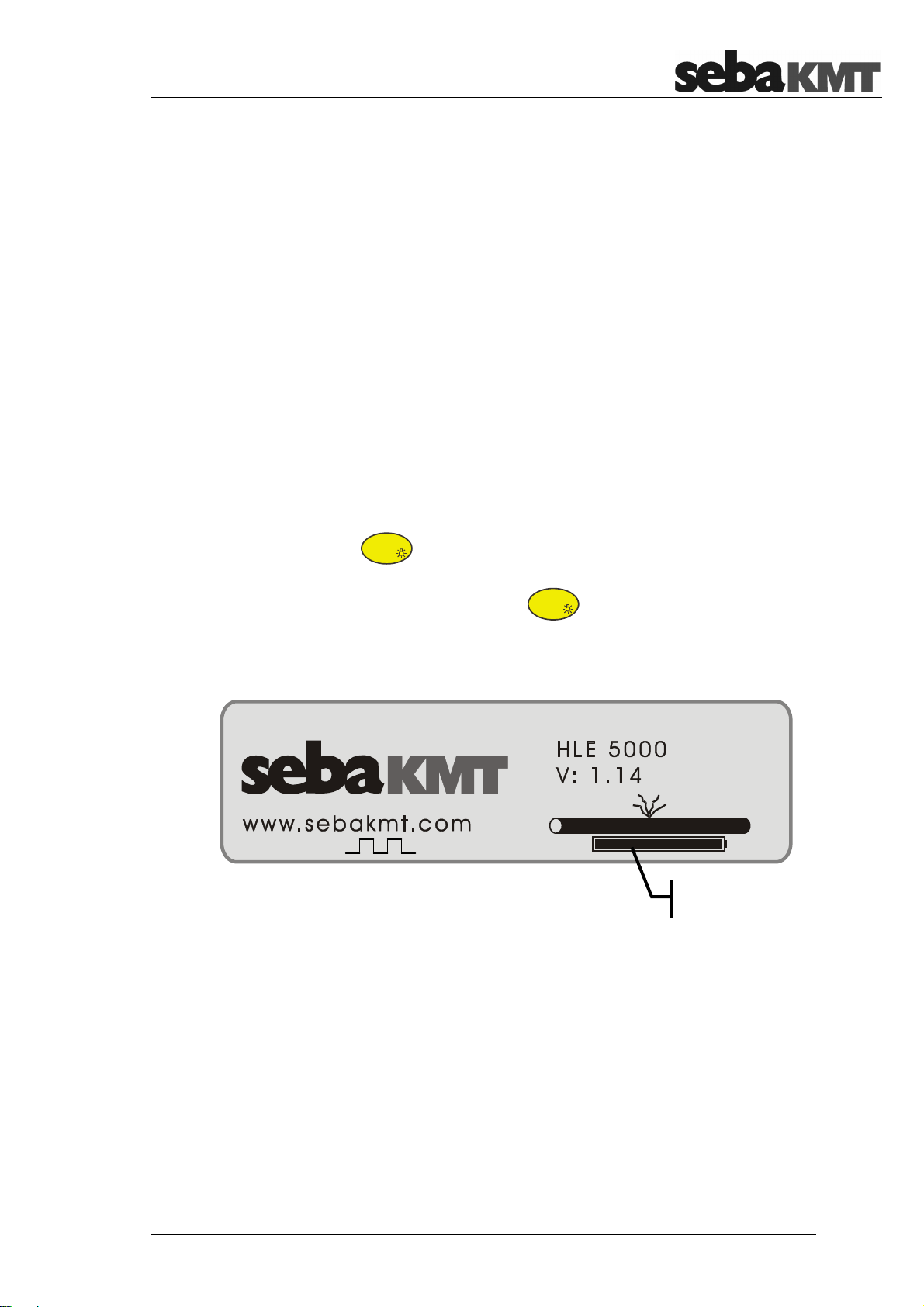
3.2 Switching on
By pushing the on/off button
turned on. The start image then appears, together with the
current version number and the battery status.
Fig 7 : Start image with version number
After a few seconds, the opening menu appears with the last
equipment settings.
the equipment will be
Battery status
MAN_HLE500_HLE5000_eng_02
Page 18

Operating instructions HLE 500/5000
0
headphone volume
setting
100 200
150
50
Setting the
0 – 4000 Hz
12
Fig 8 : Opening menu after switch-on
3.3 Volume and amplification
The HLE 5000/500 is equipped with separate controls for
volume and amplification. Thus, every user can make the
best settings for their personal characteristics.
3.3.1 Setting the volume
Using the two buttons on the right (see fig. 9) the headphone
volume can be set. To start a measurement, medium volume
- 3 scale units - should be selected.
Amplification
Fig 9 : Setting the volume
MAN_HLE500_HLE5000_eng_02
Page 19

Operating instructions HLE 500/5000
3.3.2 Setting the gain
The amplification of the microphone signal, the gain, is set
via the two soft keys, bottom right (see fig. 10). The gain is
shown via a horizontal bar. On top of this bar the gain values
of 1 to 8 can be seen.
13
Fig 10 : Setting the gain
To start a measurement, medium gain e.g. 3-4 should be
selected.
Changing the gain affects the level bar and the volume in the
headphones.
3.4 The amplification display
The bar display (fig. 11) shows both the current value of the
sound picked up and the amplified sound.
The lower, thicker bar shows the minimum value of the
measurement. When considering the nature of a leak sound,
which is a continuous noise, the display of this value provides
a much better result and is much less susceptible to pulses of
interference. This minimum value is recalculated after the
mute button has been pushed.
MAN_HLE500_HLE5000_eng_02
Page 20

Operating instructions HLE 500/5000
0
1800
–
4000
0 –
70
Curre
nt value
Minimum value
cut-off
cut-off
14
100 200
150
50
Fig 11 : Current and minimum value
0 – 4000 Hz
3.5 Filter setting (only HLE5000)
Filter settings on the HLE 5000 are very easy.
Use the soft key button in the main menu, to
get in to the filter settings.
As you can see in fig. 12, in the centre of the display, there
are 9 vertical level bars. Underneath, there is a horizontal
bar, which identifies the selected filter range.
The lower and upper cut-off is shown to the left and right of
the bars respectively.
Lower
0 - 70Hz
106Hz
240Hz
160Hz
540Hz
360Hz
1200Hz
800Hz
1800 4000Hz
Upper
Fig 12 : Filter settings
The following 9 cut-off frequencies can be set:
0 - 70, 106, 160, 240, 360, 540, 800, 1200, 1800 -4000 Hz
3.5.1 Adjusting the cut-off frequencies
To adjust the lower cut-off frequency, use the two soft key
buttons underneath , as you can see in fig. 13.
MAN_HLE500_HLE5000_eng_02
Filter range
Page 21

Operating instructions HLE 500/5000
1800
–
HYDROLUX
0 –
®
HYDROLUX
Fig 13 : Adjusting the lower filter cut-off frequency
The upper cut-off frequency is adjusted in a similar way,
using the two soft key buttons to the right, underneath
(see fig. 14).
4000 Hz
®
15
Hz
70
Fig 14 : Adjusting the upper filter cut-off frequency
For the two cut-off frequencies, you can set the 9 frequencies
specified above and can thus easily set the special filter
range for every measurement.
After the filter range has been correctly set, use the soft key
button “ESC” to return to the main menu.
3.6 Filter selection in practice
The decision about the filter settings has to be made by the
user. In general, one can say that, for measurements with
ground microphones, lower frequency ranges should be
chosen. For measurements directly on the pipe or valve
using the sensor rod, higher frequency ranges should be
MAN_HLE500_HLE5000_eng_02
Page 22

Operating instructions HLE 500/5000
chosen. Should a measurement not be successful, then a
broadband setting is to be recommended, to ensure that
none of the leak sound is filtered away.
3.6.1 Filter selection A (Ground microphone PAM W-1, PAM U with
3-point foot)
As a standard setting, a filter from 240 Hz - 540 Hz should be
used. Particularly with plastic pipes and pipes at low
operating pressures, lower frequencies can occur.
3.6.2 Filter selection B: Sensor rod (Pam U with spike)
For measurements directly on the pipe with the sensor rod,
the frequency range should be set to 540 Hz - 1200 Hz.
16
X
3.7 Mute button
To move the ground microphone, you should first of all push
the mute button
the headphones to be interrupted and the current level will be
“frozen”. This means that your hearing is protected as the
loud contact noises are suppressed. After you have chosen a
new location for the ground microphone, the mute button
X
should be pushed again. This switches the headphones
back on, the level display is updated and the minimum is
recalculated.
3.8 The histogram
The “Histogram” function is used to be able to compare a series
of sequentially recorded measurements. This can be used when
pre-locating a burst pipe with a sensor rod microphone as well
as when pinpointing the actual leak. For the HLE 5000/500 a
maximum of 9 measurements are displayed.
X
(see fig. 1). This causes the sound in
After pressing the soft key button (see fig. 1) the LCD
display switches to the histogram view and the first histogram
is activated.
MAN_HLE500_HLE5000_eng_02
Page 23

Operating instructions HLE 500/5000
The individual histogram displays consist of a dual segment
analysis (DSA), which show the current value and the
minimum value. This DSA is shown in fig. 15. The narrow
segment stands for the current value and the wide segment
shows the minimum value, which is of particular significance
when looking for burst pipes.
17
Fig 15 : Dual segment analysis (DSA)
X
With the first push of the mute button
measurement is stored and simultaneously displayed. In this
way, nine values can be stored, one after the other. When
more than nine values are measured, the first value will be
deleted and all other values will be shifted one position to the
left. The last nine values are thus always available.
Fig 16 : Histogram measurement
the current
MAN_HLE500_HLE5000_eng_02
Page 24

Operating instructions HLE 500/5000
The histogram measurement as shown in fig. 16 shows very
different current values. On the other hand the 5th DSA
shows a clear maximum for the minimum values. The burst
pipe is thus in the vicinity of the 5th measurement location.
Additionally a small graphical symbol indicates the maximum
measurement for easy recognition. To leave the histogram
measurement, press the “ESC” soft key.
3.9 Long-term measurement (HLE 5000 only)
This function is intended to record sounds over a
programmable period and then display as a graph. With this
method the identity of a water pipe can be established by
recording the flow noise of a valve. To do that, the
microphone is put onto the pipe and the long-term
measurement is started. Then, you close the valve for a
certain time (at least 2 minutes) and then open it again. If the
pipe at the listening location is identical to the shut-off pipe,
then this should be visible on the sound level curve. In fig. 17
a sound level curve like this is shown.
18
Fig 17 : Long-term measurement
To set this function, from fig. 1 the soft key is pushed.
The menu for the long-term measurement will appear as in
fig. 17. To specify the duration press the soft key (time)
repeatedly until the required measurement time is set, as
shown top right in the display. Recording durations of 3 - 10 30 minutes are available. After setting the duration, push the
(start) soft key. The measurement will start and could be
stopped early by pressing the (stop) soft key.
MAN_HLE500_HLE5000_eng_02
Page 25

Operating instructions HLE 500/5000
3.10 Location of pipes using the RSP-3 or PWG
(HLE 5000 only)
To switch the HLE 5000 into this mode, after switching on,
soft key 2 (underneath the impulse symbol ) should be
pressed whilst the welcome image is displayed.
The HLE 5000 is now in pipe location mode, shown by the
impulse symbol at the top edge of the display.
This mode of operation is particularly suited to display
impulse noise, such as the tapping of the pipe pecker or the
PWG. The horizontal level bars respond particularly
sensitively to impulses, the bar is shown much larger and is
delayed more and the filters are set to lower frequencies Of
course, if required, the filter frequencies can be altered as
usual.
The HLE5000 stays in pipe location mode until it is switched
off. After being turned on again, it will be in normal mode.
19
3.11 Switching off
The equipment is switched off by a longer press on the
button. Any measurements stored will be lost. After 35
minutes in operation, the equipment switches off
automatically.
In histogram mode the equipment will also switch off
automatically after 35 minutes, as long as the mute and the
illumination button are not used.
MAN_HLE500_HLE5000_eng_02
Page 26

Operating instructions HLE 500/5000
4 Faults
4.1 Can't switch on
Presumably the headphones are not plugged in or
headphones are being used which do not belong to the
system.
4.2 Battery monitor does not react
One or more batteries are incorrectly fitted. Open base flap
and check the polarity of the batteries. See fig. 3.
If the polarity of all of the batteries is OK, the state of every
single battery must be checked.
20
4.3 No sound can be heard
With working equipment there are two possibilities:
a. Headphones not fitted, or fitted incorrectly
X
b. The mute button
headphones are switched off. Press the mute button
X
again to restore the sound.
4.4 Scratching sounds in the headphones
This is usually caused by a poor contact. Check all contacts.
is active, which means that the
MAN_HLE500_HLE5000_eng_02
Page 27

 Loading...