

Page 1

Consultation with SebaKMT
Abwassernetze
User Manual
Correlator
COR C-300-RI
Mess- und Ortungstechnik
Measuring and Locating Technologies
Elektrizitätsnetze
Power Networks
Kommunikationsnetze
Communication Networks
Rohrleitungsnetze
Water Networks
Sewer Systems
Leitungsortung
Line Locating
Issue: 0.9 (03/2017) - EN
Article number: 88888
1
Page 2

Consultation with SebaKMT
2
Page 3
Consultation with SebaKMT
Consultation with SebaKMT
The present system manual has been designed as an operating guide and for
reference. It is meant to answer your questions and solve your problems in as fast and
easy a way as possible. Please start with referring to this manual should any trouble
occur.
In doing so, make use of the table of contents and read the relevant paragraph with
great attention. Furthermore, check all terminals and connections of the instruments
involved.
Should any question remain unanswered or should you need the help of an authorized
service station, please contact:
Seba Dynatronic
Mess- und Ortungstechnik GmbH
Dr.-Herbert-Iann-Str. 6
D - 96148 Baunach
Phone: +49 / 9544 / 68 – 0
Fax: +49 / 9544 / 22 73
E-Mail: sales@sebakmt.com
http://www.sebakmt.com
Hagenuk KMT
Kabelmesstechnik GmbH
Röderaue 41
D - 01471 Radeburg / Dresden
Phone: +49 / 35208 / 84 – 0
Fax: +49 / 35208 / 84 249
SebaKMT
All rights reserved. No part of this handbook may be copied by photographic or other means unless SebaKMT
have before-hand declared their consent in writing. The content of this handbook is subject to change without
notice. SebaKMT cannot be made liable for technical or printing errors or shortcomings of this handbook.
SebaKMT also disclaims all responsibility for damage resulting directly or indirectly from the delivery, supply,
or use of this matter.
3
Page 4

Terms of Warranty
Terms of Warranty
SebaKMT accept responsibility for a claim under warranty brought forward by a
customer for a product sold by SebaKMT under the terms stated below.
SebaKMT warrant that at the time of delivery SebaKMT products are free from
manufacturing or material defects which might considerably reduce their value or
usability. This warranty does not apply to faults in the software supplied. During the
period of warranty, SebaKMT agree to repair faulty parts or replace them with new parts
or parts as new (with the same usability and life as new parts) according to their choice.
This warranty does not cover wear parts, lamps, fuses, batteries and accumulators.
SebaKMT reject all further claims under warranty, in particular those from consequential
damage. Each component and product replaced in accordance with this warranty
becomes the property of SebaKMT.
All warranty claims versus SebaKMT are hereby limited to a period of 12 months from
the date of delivery. Each component supplied by SebaKMT within the context of
warranty will also be covered by this warranty for the remaining period of time but for 90
days at least.
Each measure to remedy a claim under warranty shall exclusively be carried out by
SebaKMT or an authorized service station.
This warranty does not apply to any fault or damage caused by exposing a product to
conditions not in accordance with this specification, by storing, transporting, or using it
improperly, or having it serviced or installed by a workshop not authorized by SebaKMT.
All responsibility is disclaimed for damage due to wear, will of God, or connection to
foreign components.
For damage resulting from a violation of their duty to repair or re-supply items,
SebaKMT can be made liable only in case of severe negligence or intention. Any liability
for slight negligence is disclaimed.
Since some states do not allow the exclusion or limitation of an implied warranty or of
consequential damage, the limitations of liability described above perhaps may not
apply to you.
4
Page 5

Terms of Warranty
Contents
Consultation with SebaKMT ........................................................................................... 3
Terms of Warranty ........................................................................................................... 4
1
1.1
1.2
2
2.1
2.2
2.3
2.4
3
3.1
3.2
4
4.1
Safety Instructions ........................................................................................... 8
General Safety Instructions and Warnings ......................................................... 8
General Notes .................................................................................................... 8
Technical description .................................................................................... 10
Function ............................................................................................................ 10
Features of the set ........................................................................................... 11
Power supply .................................................................................................... 11
Scope of delivery .............................................................................................. 13
COR C-300-RI .................................................................................................. 16
Function and design ......................................................................................... 16
Power supply .................................................................................................... 16
The Power transmitters ................................................................................. 17
Function and Design ........................................................................................ 17
4.2
4.3
4.4
4.5
5
5.1
5.2
5.3
5.4
5.5
5.6
6
6.1
6.2
6.2.1
6.2.2
6.2.3
6.2.4
Identification number (ID) ................................................................................. 19
Power supply .................................................................................................... 19
Commissioning ................................................................................................. 20
Installation ........................................................................................................ 20
The Multi sensors ........................................................................................... 21
Design and function .......................................................................................... 21
Identification number (ID) ................................................................................. 21
Power supply .................................................................................................... 22
Switching ON/OFF ........................................................................................... 22
Installation ........................................................................................................ 23
Angle adapter ................................................................................................... 23
CorreluxView Software .................................................................................. 25
User interface ................................................................................................... 25
Basic settings ................................................................................................... 27
Storage location for application database ........................................................ 27
GPS receiver port ............................................................................................. 27
System of units ................................................................................................. 27
Logarithmic or linear coherence display ........................................................... 28
6.3
6.4
6.5
Creating, renaming and deleting directories .................................................... 28
Importing data .................................................................................................. 29
Editing a map ................................................................................................... 29
5
Page 6

Terms of Warranty
6.6
Correlation ........................................................................................................ 31
6.6.1
Perform and display a correlation .................................................................... 31
6.6.2
Display and select audio blocks (Offline measurements only) ......................... 32
6.6.3
Call up the correlation analysis menu .............................................................. 33
6.6.4
Select a correlation method (Offline measurements only) ............................... 34
6
Page 7

Terms of Warranty
7
Page 8
Safety Instructions
1 Safety Instructions
1.1 General Safety Instructions and Warnings
•
Do not drop the device / the system’s components or subject it / them to
strong impacts or mechanical shocks.
•
The limits described under Technical Data may not be exceeded.
•
The device / system must be in a technically perfect condition for
measurement.
•
The indicated degree of protection can only be ensured if plugs or the
provided protection caps are put in all sockets of the device.
•
The plugs of the supplied connection cables are only compliant to the
indicated degree of protection as long as they are plugged in. Plugs
which are not connected or which are connected in a wrong way are not
protected from water and dust ingress.
•
If the O-ring seal of a socket is obviously damaged, it must be replaced
in order to ensure the total protection against water and dust ingress.
1.2 General Notes
Safety precautions
Labelling of safety
instructions
This manual contains basic instructions for the commissioning and operation of the
device / system. For this reason, it is important to ensure that the manual is always
available to the authorised and trained operator. He needs to read the manual
thoroughly. The manufacturer is not liable for damage to material or humans due to nonobservance of the instructions and safety advices provided by this manual.
Locally applying regulations have to be observed!
The following signal words and symbols are used in this manual and on the product
itself:
Signal word /
Description
symbol
CAUTION
Indicates a potential hazard which may result in moderate or minor injury
if not avoided.
NOTICE
Indicates a potential hazard which may result in material damage if not
avoided.
Serves to highlight warnings and safety instructions.
As a warning label on the product it is used to draw attention to potential
hazards which have to be avoided by reading the manual.
Serves to highlight important information and useful tips on the operation
of the device/system. Failure to observe may lead to unusable
measurement results.
Check contents
Check the contents of the package for completeness and visible damage right after
receipt. In the case of visible damage, the device must under no circumstances be taken
into operation. If something is missing or damaged, please contact your local sales
representative.
Working with products
from SebaKMT
It is important to observe the generally applicable regulations of the country in which the
device will be operated, as well as the current national accident prevention regulations
and internal company directives (work, operating and safety regulations).
8
Page 9
Safety Instructions
Use genuine accessories to ensure system safety and reliable operation. The use of
other parts is not permitted and invalidates the warranty.
Repair and
maintenance
Special transportation
requirements
Electromagnetic
radiation
Repair and maintenance work has to be carried out by SebaKMT or authorised service
partners using original spare parts only. SebaKMT recommends having the system
tested and maintained at a SebaKMT service centre once a year.
SebaKMT also offers its customers on-site service. Please contact your service centre if
needed.
The lithium batteries of the device are dangerous goods. The transport of the batteries
itselves and of devices which contain such batteries is subject to regulations based on
the UN Model Regulations “Transport of Dangerous Goods” (ST/SG/AC.10-1).
Please inform yourself about the transportation requirements and follow them when
shipping the device.
This device is designed for industrial use. When used at home it could cause
interference to other equipment, such as the radio or television.
The interference level from the line complies with the limit curve B (living area), the
radiation level complies with the limit curve A (industrial area) according to EN 55011.
Given that living areas are sufficiently far away from the planned area of operation
(industrial area), equipment in living areas will not be impaired.
For FCC:
User Information gem. FCC 15.2:
Changes or modifications not expressly approved by the party responsible for
compliance could void the user’s authority to operate the equipment
Part 15 Statement gem. FCC 15.19/RSS Gen Issue 4 Sect. 8.4
This device complies with Part 15 of the FCC Rules. Operation is subject to the following
two conditions: (1) this device may not cause harmful interference, and (2) this device
must accept any interference received, including interference that may cause undesired
operation.
9
Page 10

Technical description
2 Technical description
2.1 Function
The Correlux C-300-RI is a digital correlation system to locate leaks in drinking water
pipes.
Pressurized water at the leak location creates a noise which travels out in all directions
of the pipe. This noise is recorded, amplified and sent wirelessly to the correlation
system by two sensors (piezo microphone, hydrophone) which are attached to the pipe
(e.g. valve, hydrants).
The PC software compares both signals (correlation) and calculates the exact distance
to the leakage on the basis of the delay time of the signals, the sensor spacing and the
sound velocity in the pipe.
The Correlux C-300-RI is suitable for both immediate measurement
("Online measurement") as well as time-delayed measurement ("Offline measurement").
Online measurement
In a so-called Online measurement, the noise recording and the correlation of the data
take place at the same time.
Step Description
1
Installing the Power transmitters "A" and "B" at two measuring points.
2
Noise recording, at the same time data transfer and live data correlation on the
Correlator.
Offline measurement
In a so-called Offline measurement, the correlation of the measured data takes place
only after the noise recording has been terminated.
Step Description
1
Programming the sensors (Multi sensors and Power transmitters)
2
Installing the Power transmitters and/or Multi sensors at up to 8 measuring points.
3
Noise recording, immediately or at a preset time (e.g. at night).
4
Collecting the sensors.
5
Reading and analyzing the measured data using the Correlator.
Pinpointing
To determine the exact location of the leak after the correlation, a pinpoint search can
be performed using the Multi sensors or the ground microphone connected to the
Correlator.
10
Page 11
Technical description
2.2 Features of the set
The Correlux C-300-RI set mainly comprises the following components:
•
CorreluxView-3 Software for PC/laptop
•
C-300-RI radio interface for USB connection
•
2 Power transmitters with microphone (Transmitter A / Transmitter B)
for recording the leak noise at two measuring points and sending the recorded data
to the Correlator
The set can be extended by the following components:
•
up to 8 multi sensors
for recording the leak noise of up to 8 measuring points at the same time followed
by an "Offline-correlation"
•
hydrophones
for recording the leak noise directly at the water column
The Transport case offers space for the C-300-RI, 2 Power transmitters and
3 Multi sensors. The case is not only for storage and transportation purposes, but also
functions as a charging station for the devices.
2.3 Power supply
The COR C-300-RI is supplied by USB.
The Power transmitters and the Multi sensors come with internal rechargeable Li-Ion
batteries.
The storage places of the individual devices in the transport case function as charging
stations. As soon as a device is placed in/on its station in the case, the device is
automatically charged, provided the case is connected to the mains.
The case can be connected via the connection socket and the supplied connection
cable to either a 12 V connector of a vehicle or to the mains
11
Page 12

Technical description
NOTE
When connected to the electrical system of a car, the transport case is
powered by the vehicle's battery, even while the vehicle is not in
operation. This could result in the complete discharge of the vehicle
battery.
When you park the car, disconnect the Correlux transport case from the
vehicle power supply.
You can find more information in the chapters which describe the individual devices.
12
Page 13

Technical description
2.4 Scope of delivery
Standard accessory
Additional accessory
The basic set comprises the following devices and accessories:
Accessory Description Art.no.
COR C-300-RI USB interface 1008480
COR PT-3A Power transmitter A 1004779
COR PT-3B Power transmitter B 1004780
PAM CORR-2 2 x active universal microphone for PT-3 820019615
LG C-3 Charging unit for CPK 3/CMK 3 1006646
LK 13 Car charging adaptor, 3.5m 810000006
KR 22-5 Stereo headphones 810002087
VST T-1 2 x extension rod for PAM CORR-2 810000103
2 x nylon cord 3mm blue, 2m 304035025
CSW CorreluxView PC software 1006584
The following devices and accessories are available to extend the basic set.
Accessory Description Art.no.
COR MS-3 Multi sensor 1004815
Technical data
Power transmitter
COR PT-3A/B
CMK 3-8-MS Case for 8 Multi sensors COR MS-3 2005301
LOG TP Trivet adaptor for Sebalog Corr 128309877
LOG MWA Magnetic angled adaptor 118303355
Mounting set for COR MWA
(Screws for angled adapters)
Set of labels COR MS-3 (1 - 8) 2007321
Correlux C-300-RI is specified by the following parameters:
dimensions
Weight
Connector / Supply
Parameter Value
Sensor Piezo sensor with active amplifier (standard) /
Indicators I/O LED (device On/Off)
170 x 110 x 60 mm (without antenna)
0.6 kg
USB
hydrophone (optional)
Radio LED (radio module On/Off))
Row of LEDs (battery status or measured noise level)
2007393
Operation On/Off pushbutton
Power supply Internal rechargeable Li-Ion battery,
inductive charging
13
Page 14

Technical description
Parameter Value
Operating time min. 12 h
Connections
Dimensions (without
handle)
Weight (without sensor)
Degree of protection
Sensor (microphone/hydrophone),
Radio antenna
Ø 125 x 111 mm
0.9 kg
IP 65
14
Page 15

Technical description
Sensor
PAM CORR-2
Multi sensor
COR MS-3
Parameter Value
Type Piezo sensor with magnetic adaptor
(to be connected to Power transmitter or Correlator)
Active amplification yes
Dimensions Ø 38 x 78 mm
Weight 0.4 kg
Degree of protection IP 68
Parameter Value
Sensor Integrated piezo sensor with active amplifier
Adapter Magnetic adaptor
Indicators Status LED
Operation On/Off magnetic switch
Power supply Internal rechargeable Li-Ion battery,
inductive charging
Operating time min. 16 h
Dimensions
Ø 45 x 115 mm
Weight
Degree of protection
0.4 kg
IP 68
15
Page 16

COR C-300-RI
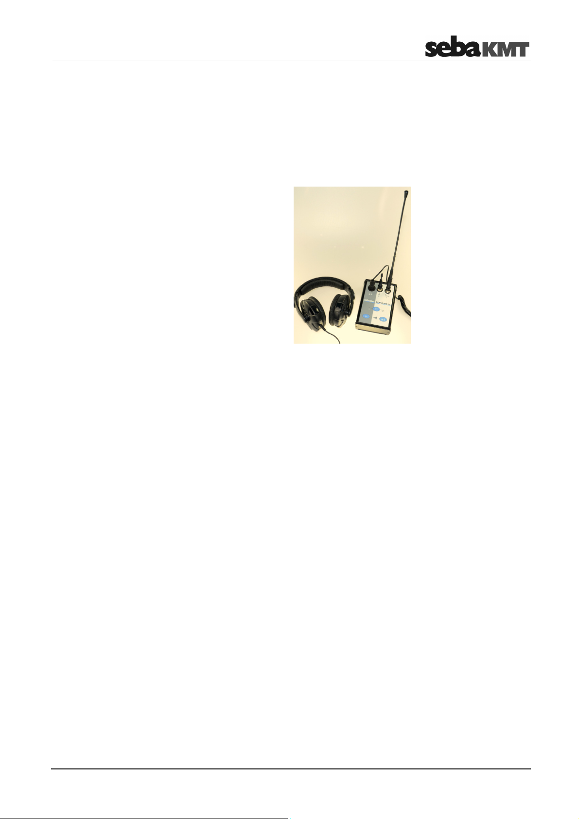
3 COR C-300-RI
3.1 Function and design
The COR C-300-RI is a portable device, acting as a radio interface between a PC or
laptop and the sensor devices of the COR C-3 system. With the C-300-RI it is possible
to program/configure the Multisensors (COR MS-3) and receive the analog signal of the
Power-Transmitters (COR PT-3).
The C-300-RI has two external connectors to connect two different antennas - one for
digital communication and one for long range analog communication.
Element Description
Headset connector
Digital antenna socket
Analog antenna socket
Audio channel switch button
A/B, A mono, B mono
Volume up/down button
3.2 Power supply
The USB connector is used for data transfer and power supply
16
Page 17

The Power transmitters
4 The Power transmitters
4.1 Function and Design
Each Power transmitter has an active amplifier for the microphone signal, a data
memory, a rechargeable Li-Ion battery, a digital radio module and an analogue radio
module with antenna inside.
The sensors have the following external characteristics:
Element Description
Microphone storage place
Sensor socket
for connecting the microphone / hydrophone
I/O pushbutton
short pressing ... switches the device on
long pressing ... Switches the device off
Antenna socket
Antenna socket for connecting the analogue radio antenna
Ventilation/venting membrane
17
Page 18

The Power transmitters
Indicator lights
The Power transmitters have the following lights (LEDs):
Element Description
LED bar
lit green ... represents the current battery level
lit red ... represents the noise level
I/O LED
lit green ... the transmitter is switched on
flashing ... the device is charging
not lit ... the transmitter is switched off
Radio LED
lit red ... the transmitter is in "Active" mode,
not lit ... the transmitter is in "Stand-by" mode,
noise measurement in progress,
measurement data is being sent to the Correlator
no measurement in progress,
no radio traffic
18
Page 19

The Power transmitters
4.2 Identification number (ID)
Each Power transmitter has its own six-digit identification number (short: ID). Using this
ID the device can be managed and clearly identified in the Correlator, computer and
within the SebaKMT-Cloud.
The ID is deduced from the last six digits of the device's serial number (short: SN). You
find the serial number on the nameplate of the device.
When entering an ID on the Correlator or computer, the preceding zero digits can be
omitted.
4.3 Power supply
Battery level
Charging
The Power transmitters are fitted with internal rechargeable Li-Ion batteries This can
power the device for approximately 12 hours.
In the Start menu of the Correlator two battery icons indicate the current battery status
of the Power transmitters.
On the Power transmitters, the current battery status is indicated by the LED bar
when it is green. If only one of five LEDs is lit, the device should be charged. Otherwise,
it switches itself off automatically.
Red light represents the recorded noise during the measurement and not the battery
status.
The Power transmitters are charged wirelessly in the transport case. The case must be
connected to a power supply. As soon as the Power transmitters are situated at their
storage places in the case, they are recharged inductively.
Charging takes approximately 12 hours. The I/O LED flashes when loading. The
LED bar indicates the progress of charging The I/O LED turns back to permanent
light as soon as the battery is full.
CAUTION
No objects must be put into empty charging stations.
Risk of fire!
The charging stations are for transport and charging of the devices only.
NOTE
Any repairs must be carried out by SebaKMT or an authorized service
partner.
Otherwise, the devices' resistance against water and dirt cannot be
guaranteed.
Do not open the device yourself. If you have problems with the battery,
please contact your SebaKMT service partner.
19
Page 20

The Power transmitters
4.4 Commissioning
Switching ON/OFF
Stand-by
4.5 Installation
To turn on, briefly press the I/O pushbutton . The I/O LED is lit green when the
device is turned on. To turn the device off, press the button until the LED goes out.
The microphone's storage place is fitted with a magnetic switch. As a result, the
Power transmitter "knows" whether the microphone is currently in use or not.
As long as the microphone rests in its storage place, the Power transmitter remains in
"Stand-by" mode. The internal analogue radio module stays off as no measuring data
needs to be transferred to the Correlator. This saves battery power.
As soon as the microphone is taken from the storage place, the Power transmitter
switches from "Stand-by" to "Active" mode. The radio module is activated. From now on,
the recorded data are directly sent to the Correlator. The row of LEDs switches from
green to red and represents the recorded noise level.
The sensors should be installed directly on the pipe but, however, you can also attach
them to valve rods or hydrants, for example, or any other position along the pipeline that
is easily accessible.
There must be the best possible contact between the sensor foot or the mounted
adapter (see below) and the pipe. If need be, clean the contact point thoroughly
(preferably with a wire brush).
In some situations it might be helpful to use one of the supplied magnetic angle
adapters.
20
Page 21

The Multi sensors
5 The Multi sensors
5.1 Design and function
Each Multi sensor has a highly sensitive piezo microphone with active amplifier, a data
memory, a rechargeable Li-Ion battery and a radio module with antenna inside.
The sensors have the following external characteristics:
Element Description
Status LED
flashes green ... Battery OK
flashes yellow ... Battery critical
flashes red ... Device needs to be re-charged
flashes rapidly ... Device is charging
no light ... Device is turned off
ON/OFF contact area I/O
Magnetic foot (detachable)
Type plate
Carrying ring (detachable)
5.2 Identification number (ID)
Each Multi sensor has its own six-digit identification number (short: ID). Using this ID the
device in the Correlator and the CorreluxView PC software can be managed and clearly
identified.
The ID is deduced from the last six digits of the device's serial number (short: SN). You
find the serial number on the nameplate of the device.
When entering an ID on the Correlator or computer, the preceding zero zero digits can
be omitted (see page Fehler! Textmarke nicht definiert.).
21
Page 22

The Multi sensors
5.3 Power supply
Battery level
Charging
The Multi sensors are fitted with internal rechargeable Li-Ion batteries This can power
the device for at least 16 hours.
In the Start menu of the Correlator up to eight battery icons can be seen. They indicate
the current battery status of the registered Multi sensors in reach. To know the exact
battery state of a Multi sensor, read the unit's configurations menu (see page Fehler!
Textmarke nicht definiert.). In the line battery status the battery level of the sensor is
shown as a percentage.
When the battery level of a Multi sensor falls below a certain threshold, the indicator
light of the device will flash red. The device must be charged. Otherwise, it switches
itself off automatically.
To charge the Power transmitters place them in the transport case. The case must be
connected to a power supply. As soon as the sensors are situated at their storage
places in the case, they are recharged inductively.
Charging takes approximately 6 hours. The units' indicator lights are rapidly flashing
during the charging process. The indicator lights turn to permanent green light as soon
as the battery is full.
CAUTION
No objects must be put into empty charging stations.
Risk of fire!
The charging stations are for transport and charging of the devices only.
NOTE
Any repairs must be carried out by an authorized service partner.
Otherwise, the devices' resistance against water and dirt cannot be
guaranteed.
Do not open the Multi sensors yourself. If you have problems with the
battery, please contact your SebaKMT service partner.
5.4 Switching ON/OFF
The Multi sensors have an internal magnetic switch.
To turn a Multi sensor on, briefly hold a magnet (e.g. the foot of another Multi sensor) in
front of the sensor's I/O area . The device turns on. The indicator light flashes
3 times.
To turn the device off, hold a magnet in front of the I/O area for approximately
2 seconds. The indicator light will flash 2 times before it goes out.
22
Page 23

The Multi sensors
5.5 Installation
The Multi sensors should be installed directly on the pipe However, you can also attach
them to valve rods or hydrants, for example, or any other position along the pipeline that
is easily accessible. Due to their powerful magnet, the sensors can also be attached
horizontally.
There must be the best possible contact between the sensor foot or the mounted
adapter (see below) and the pipe. If need be, clean the contact point thoroughly
(preferably with a wire brush).
5.6 Angle adapter
In some situations, the Multi sensor cannot be attached directly to the desired
measurement point due to its size, e.g. in very narrow shafts or similar. In such cases, it
can be helpful to use one of the supplied angle adapters.
Magnetic connection
Screw connection
Thanks to its magnetic foot, the sensor is simply placed on the
adapter. Then, the magnetic adapter can be attached to the
pipe or fitting etc.
NOTE
The sensor's type plate and I/O area must face
away from the angle adapter - as can be seen on
the picture.
Otherwise, the magnet of the angle adapter would
You can screw the angle adapter firmly to the sensor.
This can be useful as the holding strength between the angle adapter and the pipe in
general is higher than the holding strength between the angle adapter and the sensor.
When collecting the sensors, it may happen that you pull the sensor from the angle
without intention. The adapter then remains on the pipe and it could be difficult to
remove it.
Unscrew the magnetic foot from the sensor. Take one of the
supplied screws from the COR C-300-RI set to screw the angle
adapter on the sensor.
turn off the Multi sensor unintentionally.
Make sure that the sensor's type plate does face away from the
angle adapter.
23
Page 24

The Multi sensors
24
Page 25

CorreluxView Software
Menu bar
6 CorreluxView Software
6.1 User interface
The CorreluxView screen is divided into three sections - menu bar, directory tree and
display area. This screen layout remains unchanged regardless of menu level.
Directory tree
Menu bar
Directory tree
Display area
The menu bar (ribbon) allows you to access any command or function.
Function keys are combined appropriately into different segments. The CorreluxView
symbol at the top left of the menu bar allows you to access system settings for the
application.
Example: 'Folder' segment containing function buttons for managing
directories in the directory tree
The directory structure (the so-called "directory tree") of the application's internal
database is displayed to the left of the screen. Users are free to create, edit and delete
directories and subdirectories in any way they wish.
25
Page 26

CorreluxView Software
Display area
The display area is divided into the following sections:
Measurement information
(name of correlation, time of measurement,
measurement comments)
List of sensors in use
Map
(at the very top: function keys
for map management)
Element Description
Button to
•
edit the GPS data for this sensor
•
edit the comment text for this sensor
Sensor number
Identification number for this sensor
Button for deleting this sensor from the list
Button for listening to the quietest recording made by this sensor
Minimum value of this sensor (ESA value, level in dB, frequency in Hz).
The color of the field reflects the ESA value.
blue yellow
low level high level
26
Page 27

CorreluxView Software
6.2 Basic settings
You should always check basic CorreluxView software settings and adjust these if
necessary before using the application.
To open the system settings menu, proceed as follows:
Step Description
1
Click on the CorreluxView symbol at the top left of the menu bar.
2 Click on Settings in the context menu.
Result: The system settings menu opens.
6.2.1 Storage location for application database
In the Data location segment the storage location for the CorreluxView application
database is shown. This target directory was created upon initial installation of the
software. All measurement data sets that are imported to the CorreluxView application
by the Correlator are saved under this location.
You can use the Open button to open the directory.
You can use the Browse button to specify a new storage location. The application will
display a window allowing you to navigate to the new target directory for the application
database. When you are finished, click OK to confirm your change.
6.2.2 GPS receiver port
The CorreluxView application allows you to connect a GPS receiver to your computer so
you can use the software to specify GPS coordinates for sensors.
Use the drop-down menu in the GPS device segment to select the connection port for
your GPS receiver.
6.2.3 System of units
You can select whether Metric or Imperial (Anglo-American) units of measurement
are to be used in your CorreluxView application.
Open the Correlation tab. Use the drop-down menu in the Unit segment.
27
Page 28

CorreluxView Software
6.2.4 Logarithmic or linear coherence display
In the Correlation menu a Coherence curve is shown. You can select whether the
frequency axis for the coherence curve should rise linearly or logarithmically.
Open the Correlation tab. Use the drop-down menu in the Coherence segment.
Explanation: The frequency range of the Correlux C-300 system is from 0 to 3300 Hz.
Experience shows that the frequency of leak noise ranges from 0 to 1000 Hz. The
logarithmic view results in a wider display area for these lower frequencies.
Logarithmic view:
Linear view:
6.3 Creating, renaming and deleting directories
Creating a directory
Renaming a directory
To create a new directory in the directory tree, proceed as follows:
Step Description
1
In the directory tree, select the directory under which your new directory is to be
added as a subdirectory.
2 Click on New in the Folder segment.
Result: A new window opens.
3 Enter the name of your new directory, then click OK to confirm your input.
Result: The new directory has now been created in the database and appears in
the directory tree.
You may also change the name of an existing directory. Proceed as follows:
Step Description
1
Select the relevant directory in the directory tree.
2 Click on Edit in the Folder segment.
Result: A window opens.
3 Enter the new name for your directory, then click on OK to confirm your input
28
Page 29

CorreluxView Software
Deleting a directory
6.4 Importing data
To remove a directory from the directory tree, proceed as follows:
Step Description
1
Select the relevant directory in the directory tree.
2 Click on Delete in the Folder segment.
3 Answer Yes to the delete confirmation prompt.
Result: The directory as well as all measurements stored under that directory are
deleted from the database.
To import a measurement data set from the Correlator into the CorreluxView application,
proceed as follows:
Step Description
1
Connect the Correlator to your computer.
(First, establish the cable connection. Then go to the Correlator's main menu, click
on the button, then on Connect Correlator to PC, then on Connect.)
Result: Your computer will automatically recognize the Correlator as a data
storage device and display it under the name 'CORRELUX'.
2
Go to the CorreluxView directory tree and select the directory under which the
measurement is to be added. If necessary, first create a new directory.
3 Click on Import in the menu bar.
Result: A new window opens.
4
Navigate to the Correlator's root directory ('CORRELUX'). This directory will list a
set of subdirectories that contain all measurement data sets saved.
5 Select the measurement data set you want, then click on OK.
Result: The data import begins. The process may take a few seconds.
After the data transfer is complete, the measurement will appear in the directory
tree, and will also be opened for processing in the display area.
6.5 Editing a map
The Map section is intended to provide a realistic overview of the sensors and pipelines
in the measuring area.
The sensors used are shown as icons. Pipelines can be drawn between these icons and
the pipe parameters can be specified.
Provided that GPS data for the measuring points are known (i.e. the coordinates of the
measuring points have been determined and saved prior to measurement), the
CorreluxView application will automatically arrange the sensor icons in the map section
so that they correspond to reality.
29
Page 30

CorreluxView Software
Arrange sensor icons
Draw pipelines
To move and reposition sensor icons in the map section, proceed as follows:
Step Description
1
The button must be deactivated.
2
Click once on the sensor symbol you want to move.
Result: The symbol is now highlighted and "stuck" to your mouse cursor.
3
Move your mouse cursor to the new position for the symbol, then click your
mouse button again.
Result: The sensor now occupies the new position.
To draw in a new pipe section between two sensors, proceed as follows:
Step Description
1
Activate the button . It will appear highlighted.
2
In the map section, click on the first sensor (start of pipe section).
3
Move your mouse cursor to the second sensor (end of pipe section) and click on
it.
Result: A line will now connect the two sensor icons on the screen.
A window opens, allowing you to enter parameters for the new pipeline.
Edit a section /
change pipe data
4 You can use the Add and Delete buttons to divide the displayed pipeline into
individual sections if the line between the sensors is not consistently of the same
material or does not have a consistent diameter.
5
Enter pipe data (material, diameter, length) for each pipe section.
To select a section, click directly on the relevant section in the graphic.
6 Click OK to confirm your input.
Result: The window will close, and the map section will now include the new
information you entered.
Go to the map section and double-click on a given pipeline to make changes to that
pipe's data or to the way you divided it into sections. The window for inputting pipe data
will open.
30
Page 31

CorreluxView Software
6.6 Correlation
6.6.1 Perform and display a correlation
To display the correlation result for a measurement, proceed as follows:
Step Description
1
Select the relevant measurement in the directory tree.
2 Click on the Correlation button in the menu bar.
3 Result: In the case of Online measurements, a single window will appear and
display the correlation result as a curve (left graphic).
In the case of Offline measurements, the application will provide up to
28 miniature windows (thumbnails) to display the result of the multi-correlation
(right graphic).
You will probably already be familiar with these correlation diagrams from your
work with the Correlator.
Set frequency filters
Change
display area view
The frequency diagram at the very top of the screen allows you to set a frequency filter
and to repeat the correlation.
First, go to the graphic and click on your desired lower frequency limit, keeping your
mouse key held down. Then move your mouse cursor to the right and let the key go
when you've reached your desired upper frequency limit. The correlation/multicorrelation will update immediately, taking into consideration only the frequency range
marked in blue.
Using the Measurement tab at the top of the display area you can return to the view
that shows the sensor list and the map. Use the Correlation tab to call the correlation or
multicorrelation view again.
31
Page 32

CorreluxView Software
6.6.2 Display and select audio blocks (Offline measurements only)
Show audio blocks
Select audio blocks
Once you click on the thumbnail of a sensor pair, 10 additional thumbnails will open at
the right of the screen, showing the individual correlations of the 10 audio blocks
recorded by these two sensors during measurement.
Using the 10 checkboxes on the right, you have the chance to exclude, from the overall
correlation, those individual audio block correlations which are "unusable".
To do this, just deactivate the checkbox next to the audio block in question.
The thumbnail of the sensor pair's overall correlation, highlighted by a red rectangular
frame, will be updated immediately.
The "disabled" audio block will be excluded from any correlation analysis until the
corresponding checkbox is ticked again.
32
Page 33

CorreluxView Software
6.6.3 Call up the correlation analysis menu
Call up analysis menu
Design
Once you click twice on a correlation displayed by CorreluxView, the analysis menu
appears which can be used to more closely examine the correlation.
The menu which opens is very similar to the Correlator's Correlation menu.
Correlation
Coherence
Element Description
Correlation curve
with the Lag value top left whose color indicates the quality of the correlation
Tools
Coherence curve
Pipeline between A and B
Tapping the graphic opens the menu for entering pipe parameters.
Sensor number
Distance from sensor to leak
Comment field
for notes on this correlation
The buttons for analyzing correlation curve and coherence will probably also be familiar
to you from your work with the Correlator.
Zoom … To magnify a section of the correlation curve
Click on the button, then select the area in the diagram on which you want
to zoom.
Zoom opt. … Click on the button to toggle between the following two
displays:
•
Display of the entire correlation range
•
Display of only that portion of the correlation curve which refers to
the pipe section between the two measuring points
Peak suppression … To hide a section of the curve from view
Click on the button, then select the area in the diagram that you want to
suppress.
Reset … Sets all analysis tools as well as the correlation curve back to
their initial states.
33
Page 34

CorreluxView Software
Automatic search for filter … Provides 10 possible filter settings for
selection
Click on the button. The application will open a window which suggests 10
possible frequency filter settings, with the most sensible highlighted.
Bandpass … To delimit a frequency range
The button must first be activated. Then go to the coherence diagram and
select your desired frequency range.
The correlation is updated, suppressing those frequencies which fall
outside the range you selected.
Broadband … Resets the frequency filter
Bandstop … To suppress a frequency range.
The button must first be activated. Then go to the coherence diagram and
select your desired frequency range.
The correlation is updated, hiding the selected frequency range from view.
Print … Allows to print out the correlation and coherence curves that are
currently displayed. Clicking on the button will open the printer dialog
window.
Using the radio buttons in the Show segment bottom right, you can
select whether the two sensors (left and right of the correlation
curve) are described by their Sensor number, Identification number
or commentary.
6.6.4 Select a correlation method (Offline measurements only)
In the case of Offline measurements, one of the following two correlation methods for
the multi-correlation can be chosen:
Correlation methods
Averaged correlation
ABC
The CorreluxView application calculates
an average over the 10 individual audio
block correlations carried out for a sensor
pair. This "averaged correlation" is
displayed in the sensor pair's thumbnail.
"Disabled" audio blocks are excluded from
the calculation.
Minimum Block Correlation
The CorreluxView application selects the
quietest audio block out of the 10 individual
correlations for a sensor pair and displays
this in the sensor pair's thumbnail.
"Disabled" audio blocks are excluded from
the calculation.
MBC
In the menu bar, set the ABC slide control
to ON.
In the menu bar, set the MBC slide control
to ON.
34
Page 35

CorreluxView Software
Tento symbol indikuje, že výrobek nesoucí takovéto označení nelze likvidovat společně s běžným domovním odpadem. Jelikož se jedná o produkt obchodovaný mezi
podnikatelskými subjekty (B2B), nelze jej likvidovat ani ve veřejných sběrných dvorech. Pokud se potřebujete tohoto výrobku zbavit, obraťte se na organizaci specializující
se na likvidaci starých elektrických spotřebičů v blízkosti svého působiště.
Dit symbool duidt aan dat het product met dit symbool niet verwijderd mag worden als gewoon huishoudelijk afval. Dit is een product voor industrieel gebruik, wat betekent
dat het ook niet afgeleverd mag worden aan afvalcentra voor huishoudelijk afval. Als u dit product wilt verwijderen, gelieve dit op de juiste manier te doen en het naar een
nabij gelegen organisatie te brengen gespecialiseerd in de verwijdering van oud elektrisch materiaal.
This symbol indicates that the product which is marked in this way should not be disposed of as normal household waste. As it is a B2B product, it may also not be disposed
of at civic disposal centres. If you wish to dispose of this product, please do so properly by taking it to an organisation specialising in the disposal of old electrical equipment
near you.
Този знак означава, че продуктът, обозначен по този начин, не трябва да се изхвърля като битов отпадък. Тъй като е B2B продукт, не бива да се изхърля и в
градски пунктове за отпадъци. Ако желаете да извърлите продукта, го занесете в пункт, специализиран в изхвърлянето на старо електрическо оборудване.
Dette symbol viser, at det produkt, der er markeret på denne måde, ikke må kasseres som almindeligt husholdningsaffald. Eftersom det er et B2B produkt, må det heller ikke
bortskaffes på offentlige genbrugsstationer. Skal dette produkt kasseres, skal det gøres ordentligt ved at bringe det til en nærliggende organisation, der er specialiseret i at
bortskaffe gammelt el-udstyr.
Sellise sümboliga tähistatud toodet ei tohi käidelda tavalise olmejäätmena. Kuna tegemist on B2B-klassi kuuluva tootega, siis ei tohi seda viia kohalikku jäätmekäitluspunkti.
Kui soovite selle toote ära visata, siis viige see lähimasse vanade elektriseadmete käitlemisele spetsialiseerunud ettevõttesse.
Tällä merkinnällä ilmoitetaan, että kyseisellä merkinnällä varustettua tuotetta ei saa hävittää tavallisen kotitalousjätteen seassa. Koska kyseessä on yritysten välisen kaupan
tuote, sitä ei saa myöskään viedä kuluttajien käyttöön tarkoitettuihin keräyspisteisiin. Jos haluatte hävittää tämän tuotteen, ottakaa yhteys lähimpään vanhojen
sähkölaitteiden hävittämiseen erikoistuneeseen organisaatioon.
Ce symbole indique que le produit sur lequel il figure ne peut pas être éliminé comme un déchet ménager ordinaire. Comme il s’agit d’un produit B2B, il ne peut pas non plus
être déposé dans une déchetterie municipale. Pour éliminer ce produit, amenez-le à l’organisation spécialisée dans l’élimination d’anciens équipements électriques la plus
proche de chez vous.
Cuireann an siombail seo in iúl nár cheart an táirgeadh atá marcáilte sa tslí seo a dhiúscairt sa chóras fuíoll teaghlaigh. Os rud é gur táirgeadh ghnó le gnó (B2B) é, ní féidir
é a dhiúscairt ach oiread in ionaid dhiúscartha phobail. Más mian leat an táirgeadh seo a dhiúscairt, déan é a thógáil ag eagraíocht gar duit a sainfheidhmíonn i ndiúscairt
sean-fhearas leictrigh.
Dieses Symbol zeigt an, dass das damit gekennzeichnete Produkt nicht als normaler Haushaltsabfall entsorgt werden soll. Da es sich um ein B2B-Gerät handelt, darf es
auch nicht bei kommunalen Wertstoffhöfen abgegeben werden. Wenn Sie dieses Gerät entsorgen möchten, bringen Sie es bitte sachgemäß zu einem Entsorger für
Elektroaltgeräte in Ihrer Nähe.
Αυτό το σύµβολο υποδεικνύει ότι το προϊόν που φέρει τη σήµανση αυτή δεν πρέπει να απορρίπτεται µαζί µε τα οικιακά απορρίµατα. Καθώς πρόκειται για προϊόν B2B, δεν
πρέπει να απορρίπτεται σε δηµοτικά σηµεία απόρριψης. Εάν θέλετε να απορρίψετε το προϊόν αυτό, παρακαλούµε όπως να το παραδώσετε σε µία υπηρεσία συλλογής
ηλεκτρικού εξοπλισµού της περιοχής σας.
Ez a jelzés azt jelenti, hogy az ilyen jelzéssel ellátott terméket tilos a háztartási hulladékokkal együtt kidobni. Mivel ez vállalati felhasználású termék, tilos a lakosság
számára fenntartott hulladékgyűjtőkbe dobni.Ha a terméket ki szeretné dobni, akkor vigye azt el a lakóhelyéhez közel működő, elhasznált elektromos berendezések
begyűjtésével foglalkozó hulladékkezelő központhoz.
Questo simbolo indica che il prodotto non deve essere smaltito come un normale rifiuto domestico. In quanto prodotto B2B, può anche non essere smaltito in centri di
smaltimento cittadino. Se si desidera smaltire il prodotto, consegnarlo a un organismo specializzato in smaltimento di apparecchiature elettriche vecchie.
Šī zīme norāda, ka iztrādājumu, uz kura tā atrodas, nedrīkst izmest kopā ar parastiem mājsaimniecības atkritumiem. Tā kā tas ir izstrādājums, ko cits citam pārdod un lieto
tikai uzņēmumi, tad to nedrīkst arī izmest atkritumos tādās izgāztuvēs un atkritumu savāktuvēs, kas paredzētas vietējiem iedzīvotājiem. Ja būs vajadzīgs šo izstrādājumu
izmest atkritumos, tad rīkojieties pēc noteikumiem un nogādājiet to tuvākajā vietā, kur īpaši nodarbojas ar vecu elektrisku ierīču savākšanu.
Šis simbolis rodo, kad juo paženklinto gaminio negalima išmesti kaip paprastų buitinių atliekų. Kadangi tai B2B (verslas verslui) produktas, jo negalima atiduoti ir buitinių
atliekų tvarkymo įmonėms. Jei norite išmesti šį gaminį, atlikite tai tinkamai, atiduodami jį arti jūsų esančiai specializuotai senos elektrinės įrangos utilizavimo organizacijai.
Dan is-simbolu jindika li l-prodott li huwa mmarkat b’dan il-mod m’għandux jintrema bħal skart normali tad-djar. Minħabba li huwa prodott B2B , ma jistax jintrema wkoll
f’ċentri ċiviċi għar-rimi ta’ l-iskart. Jekk tkun tixtieq tarmi dan il-prodott, jekk jogħġbok għamel dan kif suppost billi tieħdu għand organizzazzjoni fil-qrib li tispeċjalizza fir-rimi ta’
tagħmir qadim ta’ l-elettriku.
Dette symbolet indikerer at produktet som er merket på denne måten ikke skal kastes som vanlig husholdningsavfall. Siden dette er et bedriftsprodukt, kan det heller ikke
kastes ved en vanlig miljøstasjon. Hvis du ønsker å kaste dette produktet, er den riktige måten å gi det til en organisasjon i nærheten som spesialiserer seg på kassering av
gammelt elektrisk utstyr.
Ten symbol oznacza, że produktu nim opatrzonego nie należy usuwać z typowymi odpadami z gospodarstwa domowego. Jest to produkt typu B2B, nie należy go więc
przekazywać na komunalne składowiska odpadów. Aby we właściwy sposób usunąć ten produkt, należy przekazać go do najbliższej placówki specjalizującej się w
usuwaniu starych urządzeń elektrycznych.
Este símbolo indica que o produto com esta marcação não deve ser deitado fora juntamente com o lixo doméstico normal. Como se trata de um produto B2B, também não
pode ser deitado fora em centros cívicos de recolha de lixo. Se quiser desfazer-se deste produto, faça-o correctamente entregando-o a uma organização especializada na
eliminação de equipamento eléctrico antigo, próxima de si.
Acest simbol indică faptul că produsul marcat în acest fel nu trebuie aruncat ca şi un gunoi menajer obişnuit. Deoarece acesta este un produs B2B, el nu trebuie aruncat nici
la centrele de colectare urbane. Dacă vreţi să aruncaţi acest produs, vă rugăm s-o faceţi într-un mod adecvat, ducând-ul la cea mai apropiată firmă specializată în colectarea
echipamentelor electrice uzate.
Tento symbol znamená, že takto označený výrobok sa nesmie likvidovať ako bežný komunálny odpad.Keďže sa jedná o výrobok triedy B2B, nesmie sa likvidovať ani na
mestských skládkach odpadu. Ak chcete tento výrobok likvidovať, odneste ho do najbližšej organizácie, ktorá sa špecializuje na likvidáciu starých elektrických zariadení.
Ta simbol pomeni, da izdelka, ki je z njim označen, ne smete zavreči kot običajne gospodinjske odpadke. Ker je to izdelek, namenjen za druge proizvajalce, ga ni dovoljeno
odlagati v centrih za civilno odlaganje odpadkov. Če želite izdelek zavreči, prosimo, da to storite v skladu s predpisi, tako da ga odpeljete v bližnjo organizacijo, ki je
specializirana za odlaganje stare električne opreme.
Este símbolo indica que el producto así señalizado no debe desecharse como los residuos domésticos normales. Dado que es un producto de consumo profesional,
tampoco debe llevarse a centros de recogida selectiva municipales. Si desea desechar este producto, hágalo debidamente acudiendo a una organización de su zona que
esté especializada en el tratamiento de residuos de aparatos eléctricos usados.
Den här symbolen indikerar att produkten inte får blandas med normalt hushållsavfall då den är förbrukad. Eftersom produkten är en så kallad B2B-produkt är den inte
avsedd för privata konsumenter, den får således inte avfallshanteras på allmänna miljö- eller återvinningsstationer då den är förbrukad. Om ni vill avfallshantera den här
produkten på rätt sätt, ska ni lämna den till myndighet eller företag, specialiserad på avfallshantering av förbrukad elektrisk utrustning i ert närområde.
35
 Loading...