

Sears 315.17506 User Manual
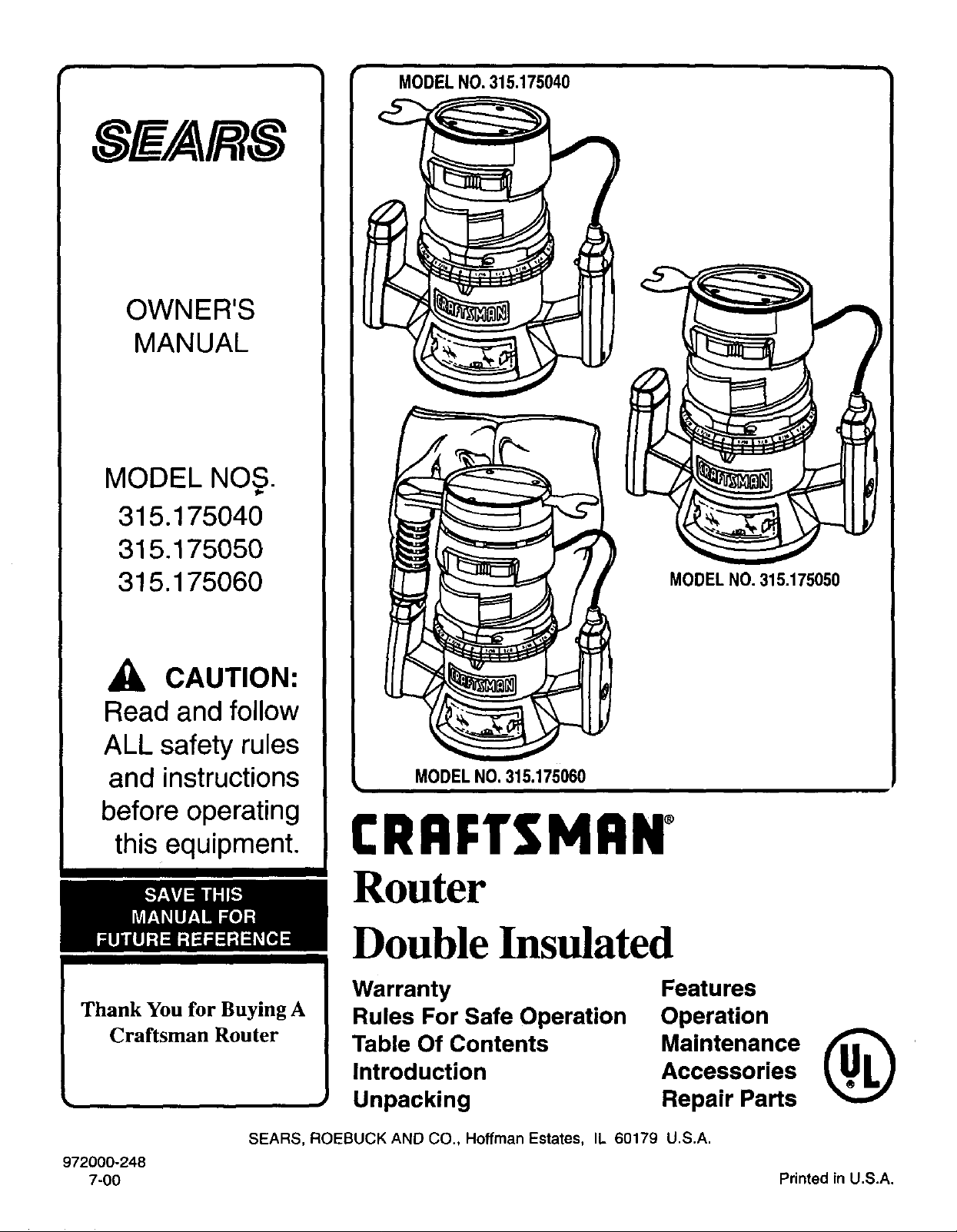
OWNER'S
MANUAL
MODEL NOS.
315.175040
315.175050
315.175060
CAUTION:
Read and follow
ALL safety rules
and instructions
before operating
this equipment.
Thank You for Buying A
Craftsman Router
MODEL NO.315.175050
MODELNO. 315.175060
CRRFTSMRNo
Router
Double Insulated
Warranty
Rules For Safe Operation
Table Of Contents
Introduction
Unpacking
Features
Operation
Accessories
Maintenance (_
Repair Parts
SEARS, ROEBUCK AND CO., Hoffman Estates, IL 60179 U.S.A.
972000-248
7-00 Printed in U.S.A.

FULL ONE YEAR WARRANTY ON CRAFTSMAN ROUTER
If this Craftsman Router fails to give complete satisfaction within one year from the date of purchase, RETURN IT
TO THE NEAREST SEARS STORE IN THE UNITED STATES, and Sears will repair it, free of charge.
If this Craftsman Router is used for commercial or rental purposes, this warranty applies for only 90 days from the
date of purchase.
This warranty gives you specific legal rights, and you may also have other rights which vary from state to state.
Sears, Roebuck and Co., DEPT. 817 WA, Hoffman Estates, IL 60179
The purpose of safety symbols is to attract your attention to possible dangers. The safety symbols, and their
explanations with them, deserve your careful attention and understanding. The safety warnings do not by
themselves eliminate any danger. The instructions or warnings they give are not substitutes for proper accident
prevention measures.
SYMBOL
i
A
MEANING
SAFETY ALERT SYMBOL:
Indicates caution or warning. May be used in conjunction with other symbols or pictographs.
WARNING: Failure to obey a safety warning can result in serious injuryto yourself or to others. Always
follow the safety precautions to reduce the risk of fire, electric shock and personal injury.
CAUTION: Failure to obey a safety warning may result in property damage or personal injuryto yourself
or to others. Always follow the safety precautions to reduce the risk of fire, electric shock and personal
injury.
J
NOTE: Advises you of information or instructionsvital to the operation or maintenance of the equipment.
DOUBLE INSULATION isa safety concept inelectric power
tools which eliminates the need for the usual three wire
grounded power cord and grounded supplysystem. Wherever
there iselectric current inthe toolthere are twocomplete sets
of insulation to protect the user. All exposed metal parts are
isolatedfrom internal metal motorcomponents with protecting
insulation.
ELECTRICAL CONNECTION
Your router has a precision built electric motor. It should be connected to a power supply that is 120 volts, 60 Hz, AC only
(normal household current), Do not operate this tool on direct current (DC). A voltage drop of more than 10 percent will
cause a loss of power and the motor will overheat. If your tool does not operate when plugged into an outlet, double-check
the power supply.
Look for this symbol to point out important safety precautions. [
IMPORTANT - Servicing of a tool with double insulation
requires extreme care and knowledge of the system and
should be performed only by a qualified service technician.
For service we suggest you return the tool to your nearest
Sears Storefor repair. Always'useoriginalfactory replacement
parts when servicing.
,&
L
It means attention!!! Your safety is involved.
I
J
Page 2

,WARNING:
WARNING:
Do not attempt to operate this tool until you have
read thoroughly and understand completely all
instructions, safety rules, etc. contained in this
manual. Failure to comply can result in accidents
involving fire, electric shock, or serious personal
injury. Save owner's manual and review frequently
for continuing safe operation, and instructing others
who may use this tool.
READ ALL INSTRUCTIONS
.
KNOW YOUR POWER TOOL. Read owner's
manual carefully. Learn its applications and
limitations as well as the specific potential hazards
related to this tool.
.
GUARD AGAINST ELECTRICAL SHOCK by
preventing body contact with grounded surfaces.
Forexample: Pipes, radiators, ranges, refrigerator
enclosures.
3. KEEP GUARDS IN PLACE and in working order.
4. KEEP WORK AREA CLEAN. Cluttered areas
and benches invite accidents.
The double insulated system is intended to protect the
user from shock resulting from a break in the tool's
internal wiring. Observe all normal safety precautions
related to avoiding electrical shock.
11.
ALWAYS WEAR SAFETY GLASSES. Everyday
eyeglasses have only impact-resistant lenses;
they are NOT safety glasses.
12.
PROTECT YOUR LUNGS. Wear a face or dust
mask if operation is dusty.
13.
PROTECT YOUR HEARING. Wear hearing
protection during extended periods of operation.
14.
DON'T ABUSE CORD. Never carry tool by cord
or yank it to disconnect from receptacle. Keep
cord from heat, oil and sharp edges.
15.
SECURE WORK. Use clamps or a vise to hold
work. Both hands are needed to operate the tool.
16.
DON'T OVERREACH. Keep proper footing and
balance at all times. Do not use on a ladder or
unstable support.
5. AVOID DANGEROUS ENVIRONMENT. Don't 17.
use power tool in damp or wet locations or expose
to rain. Keep work area well lit.
6. KEEP CHILDREN AND VISITORS AWAY. All
visitors should wear safety glasses and be kept 18.
a safe distance from work area. Do not let
visitors contact tool or extension cord.
.
STORE IDLE TOOLS. When not in use tools
should be stored in a dry and high or locked-up
place - out of the reach of children.
,
DON'T FORCE TOOL. It will do the job better
and safer at the rate for which it was designed.
9.
USE RIGHT TOOL. Don't force small tool or
attachment to do the job of a heavy duty tool.
Don't use tool for purpose not intended - for
example - A circular saw should never be used
for cutting tree limbs orlogs.
10.
WEAR PROPER APPAREL. Do notwear loose
clothing or jewelry that can get caught in tool's
moving parts and cause personal injury. Rubber
gloves and non-skid footwear are recommended
when working outdoors. Wear protective hair
covering to contain long hair and keep it from
being drawn into nearby air vents.
MAINTAIN TOOLS WITH CARE. Keep tools
sharp at all times, and clean for best and safest
performance. Follow instructionsfor lubricating
and changing accessories.
DISCONNECT TOOLS. When not in use, before
servicing, or when changingattachments, blades,
bits,cutters, etc., alltools shouldbe disconnected
from power supply.
19.
REMOVE ADJUSTING KEYS AND WRENCHES.
Form habit of checking to see that keys and
adjusting wrenches are" removed from tool be-
fore turning it on.
20.
AVOID ACCIDENTAL STARTING. Don't carry
plugged-in tools with finger on switch. Be sure
switch is off when plugging in.
21.
MAKE SURE YOUR EXTENSION CORD IS IN
GOOD CONDITION. When using an extension
cord, be sure to use one heavy enough to carry the
current your product will draw. An undersized cord
will cause a drop in line voltage resulting in loss of
power and overheating. A wire gage size (A.W.G.)
of at least 14 is recommended for an extension
cord 100 feet or less in length. A cord exceeding
100 feet is not recommended. If in doubt, use the
next heavier gage. The smaller the gage number,
the heavier the cord.
Page 3
RULES FOR SAFE OPERATION (Continued)
22. OUTDOOR USE EXTENSION CORDS. When tool 33.
is used outdoors, use only extension cords suitable
for use outdoors. Outdoor approved cords are
marked with the suffix W-A, for example - SJTW-A
34.
orSdOW-A.
23. KEEP CUTTERS CLEAN AND SHARP. Sharp
cutters minimize stalling and kickback.
24. KEEP HANDS AWAY FROM CUTTING AREA.
Keep hands away from cutters. Do not reach
underneath work while cutter is rotating. Do not
attempt to remove material while cutter is rotating.
25. NEVER USE IN AN EXPLOSIVE ATMOSPHERE.
Normal sparking of the motor could ignite fumes.
26. INSPECT TOOL CORDS PERIODICALLY and
if damaged, have repaired at your nearest Sears
Repair Center. Stay constantly aware of cord
location.
INSPECT EXTENSION CORDS PERIODI-
27.
CALLY and rep,lace if damaged.
28.
KEEP HANDLES DRY, CLEAN, AND FREE
FROM OIL AND GREASE. Always use a clean
cloth when cleaning. Never use brake fluids,
gasoline, petroleum-based products or any strong
solvents to clean your tool.
29.
STAY ALERT. Watch what you are doing and
use common sense. Do not operate tool when
you are tired. Do not rush.
CHECK DAMAGED PARTS. Before further use
30.
of the tool, a guard or other part that is damaged
should be carefully checked to determine that it
will operate properly and perform its intended
function. Check for alignment of moving parts,
binding of moving parts, breakage of parts,
mounting, and any other conditions that may
affect its operation. A guard or other part that is
damaged should be properly repaired or replaced
by an authorized service center unless indicated
elsewhere in this instruction manual.
31. DO NOT USE TOOL IF SWITCH DOES NOT
TURN IT ON AND OFF. Have defective switches
replaced by an authorized service center.
32. INSPECT FOR and remove all nails from lumber
before routing.
35.
36. DO NOT USE TOOL UNDER "BROWN-OUT"
37. WHEN USING THIS ROUTER WITH A
38. SAVE THESE INSTRUCTIONS. Review them
DRUGS, ALCOHOL, MEDICATION. Do not
operate tool while under the influence of drugs,
alcohol, or any medication.
WHEN SERVICING USE ONLY IDENTICAL
CRAFTSMAN REPLACEMENT PARTS.
POLARIZED PLUGS. To reduce the risk of
electric shock, this tool has a polarized plug (one
blade is wider than the other). This plug will fit in
a polarized outlet only one way. If the plug does
not fit fully in the outlet, reverse the plug. If it still
does not fit, contact a qualified electrician to
instatl the proper outlet. Do not change the plug
in any way.
OR OTHER LOW VOLTAGE CONDITIONS.
Also, do not use with any device that could cause
the power supply voltage to change.
ROUTER TABLE, HELP PREVENT POS-
SIBLE SERIOUS INJURY BY KEEPING THE
CUTTER GUARDED AT ALL TIMES. Use only
router tables, with guards, that have been de-
signed for use on routers that are of this type,
size, and weight.
frequently and use them to instruct others who
may use this tool. If you loan someone this tool,
loan them these instructions also.
WARNING:
Some dust created by power sanding, sawing, grinding,
drilling, and other construction activities contains
chemicals known to cause cancer, birth defects or
other reproductive harm. Some examples of these
chemicals are: •.
• lead from lead-based paints,
• crystalline silica from bricks and cement
and other masonry products, and
• arsenic and chromium from chemically-
treated lumber.
Your risk from these exposures varies, depending on
how often you do this type of work. To reduce your
exposure to these chemicals: work in a well ventilated
area, and work with approved safety equipment, such '
as those dust masks that are specially designed to filter
out microscopic particles.
Page 4
• Warranty ................................................ 2
• Rules For Safe Operation ................. 2-4
• Table Of Contents ................................. 5
• Introduction and Product
Specifications ....................................... 6
• Unpacking ............................................. 7
• Features .............................................. 7-9
Switch .................................................. 7
Lock-On Button ....................................... 7
Chip Shield ............................................. 7
Wrench Storage Area ............................. 7
Variable Speed (Model Nos.
315.175050 and 315.175060 Only) ........ 7
Dust Bag Assembly
(Model No. 315.175060 Only) ................ 7
To Install Dust Bag ............................ 7
To Empty Du_ Bag ........................... 7
Know Your Router .................................. 8
Model No. 315.175040 ...................... 8
Model No. 315.175050 ...................... 9
Model No. 315.175060 ...................... 9
• Operation ........................................ 10-17
Installing/Removing Cutters .................. 10
Depth Of Cut Adjustments .................... 11
Depth Of Cut Adjustments When
Mounted To A Router Table ................. 12
Variable Speed (Model Nos.
315. 175050 and 315.175060) ............. 12
Practice Before Actual Use ................... 12
Routing ................................................ 13
Freehand Routing ................................. 13
Proper Feeding ..................................... 14
Speed Selections (Model Noso
315.175050 and 315.175060 Only) ...... 14
Rate Of Feed ........................................ 14
Force Feeding ...................................... 14
Too Slow Feeding ................................. 14
Depth Of Cut ......................................... 15
Direction Of Feed and Thrust ............... 15
Routing ................................................ 15
Starting and Ending A Cut
Internal Routing ............................... 16
Edging With Pilot Bits ........................... 16
Edge Routing ........................................ 16
Routing With Guide Bushings ............... 17
Router Tables ....................................... 17
• Maintenance ................................... 17-22
Switch Replacement
(Model No. 315.175040) ....................... 17
Switch Replacement (Model Nos.
315.175050 and 315.175060) .............. 18
Light Bulb Replacement ....................... 19
Proper Care Of Cutters ......................... 19
Proper Care Of Collet ........................... 19
Lubrication ............................................ 19
Helpful Hints ......................................... 19
General ................................................ 20
Extension Cords. .................................. 20
• Accessories ........................................ 21
• Exploded View and Parts List ...... 22-27
• Parts Ordering / Service ..................... 28
t j
Page 5
Congratulations and thank you for buying this
Craftsman router. It has been designed, engineered and
manufactured to provide you with Sears high standard of
dependability, ease of operation, and operator safety.
Properly cared for, it will give you years of rugged, trouble-
free performance.
Your router has many features for making routing operations
more pleasant and enjoyable. Safety, performance and
dependability have been given top priority in the design of
this router making it easy to maintain and operate.
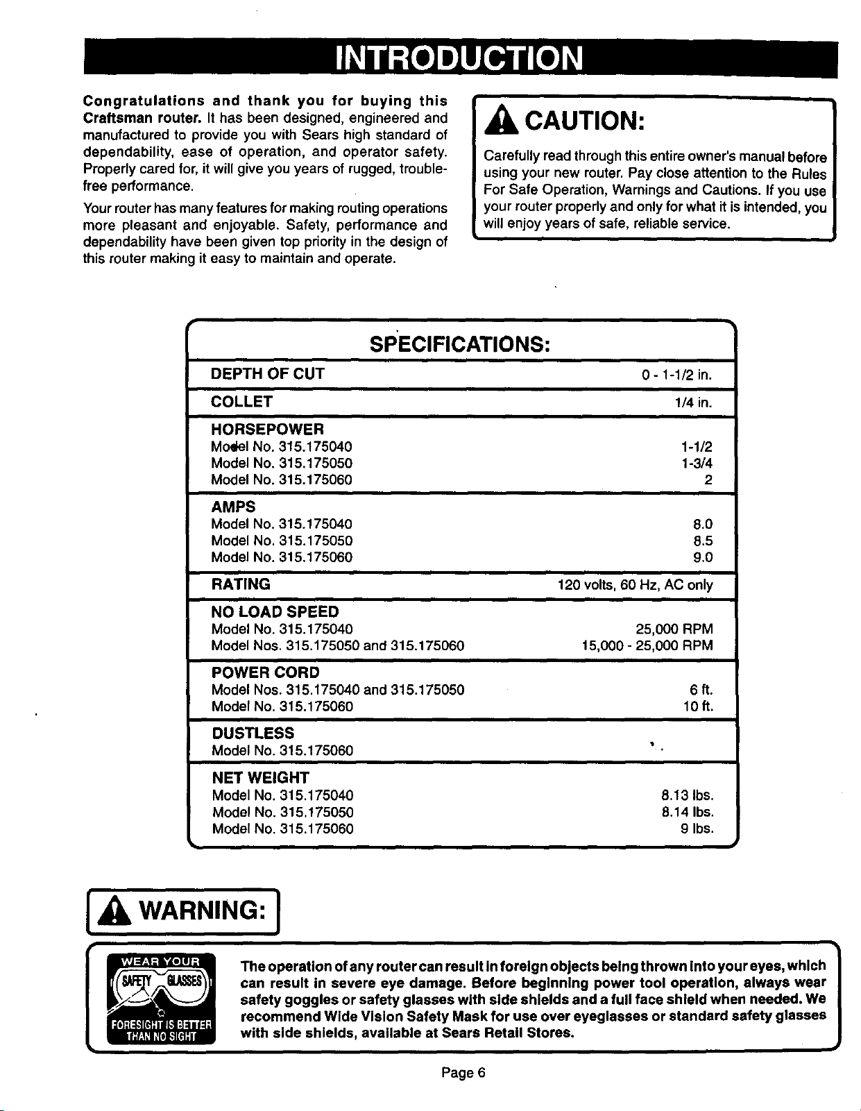
SPECIFICATIONS:
CAUTION:
Carefully read through this entire owner's manual before
using your new router. Pay close attention to the Rules
For Safe Operation, Warnings and Cautions. If you use
your router properly and only for what it is intended, you
will enjoy years of safe, reliable service.
DEPTH OF CUT
COLLET
HORSEPOWER
Model No. 315.175040
Model No. 315.175050
Model No. 315.175060
AMPS
Model No. 315.175040
Model No. 315.175050
Model No. 315.175060
RATING
NO LOAD SPEED
Model No. 315.175040
Model Nos. 315.175050 and 315.175060
POWER CORD
Model Nos. 315,175040 and 315.175050
Model No. 315.175060
DUSTLESS
Model No. 315.175060
0 - 1-1/2 in.
1/4 in.
1-1/2
1-3/4
2
8.0
8.5
9.0
120 volts, 60 Hz, AC only
25,000 RPM
15,000 - 25,000 RPM
6ft.
10ft.
NET WEIGHT
Model No. 315.175040
Model No. 315, t 75050
Model No. 315.175060
WARNING: ]
The operation of any router can result in foreign objects being thrown into your eyes, which
can result in severe eye damage. Before beginning power tool operation, always wear
safety goggles or safety glasses with side shields and a full face shield when needed. We
recommend Wide Vision Safety Mask for use over eyeglasses or standard safety glasses
with side shields, available at Sears Retail Stores.
8.13 Ibs.
8.14 Ibs.
9 Ibs.
Page 6
Your router has been shipped completely assembled and
ready for use. Inspect it carefully to make sure no breakage
or damage has occurred during shipping. If any parts are
damaged or missing, contact your nearest Sears Retail
Store to obtain replacement parts before attempting to
operate router. A wrench and this owner's manual are also
included.
SWITCH
To turn your router ON, depress the switch trigger, Release
switch trigger to turn your router OFF,
LOCK-ON BUTTON
The switch ofyour router is equipped with a lock-on feature
which is convenient when operating for extended periods of
time. To lock on, depress the trigger, push inthe lock button
located on the side ofthe handle_then while holding the lock
button pushed in, release tke trigger. To release the lock,
depress the trigger and release it.
,WARNING:
Before connecting your router to power supply source,
always check to be sure it is not in lock-on position
(depress and release switch trigger). Failure to do so
could result in accidental starting of your router resulting
in possible serious injury. Also, do not lock the trigger on
jobs where your router may need to be stopped suddenly.
CHIP SHIELD
A clear plastic chip shield is installed on the front of your
router for protection against flying dustand chips. The shield
isdesigned to fit the opening ofthe router base. If necessary
to remove chip shield, squeeze thetabs on each end and pull
outward. To replace, squeeze the tabs at each end, fit into
opening, then release. NOTE: Model No. 315.175060 has a
chip shield on the front and rear opening of the router base.
For your protection, do not use router without chip
shield(s) properly in place. Ifdesired, the horsepower label
can be removed from chip shield by simply peeling off.
WRENCH STORAGE AREA
Your router has a wrench storage area located onthe topend
cap portionofthe motor housing.When installingor removing
cutters, remove the wrench from its storage area. Proper
storage of wrench when not in use will help reduce the
possibility of losing wrench.
VARIABLE SPEED SWITCH WITH ELECTRONIC
SPEED CONTROL
(MODEL NOS. 315.175050 AND 315.175060 ONLY)
See Figures lb and lc.
Your router has advanced electronic features, designed to
assist you in getting the maximum use from your router. By
WARNING:
If any parts are missing, do not operate your router until
the missing parts are replaced. Failure to do so could
result in possible serious personal injury.
making proper speed selections, your router can be adjusted
to specific routing needs. This eliminates much of the guess
work previously needed to perform a given job. Both the
experienced and inexperienced router users benefit,
obtaining professional like results with fewer job errors.
The variable speed control allows the router speed to be
adjusted from 15,000 to 25,000 rpm. The variable speed
control selector is conveniently located outside the right
handle near the operator's thumb or hand.
Speed can be set according to the approximate cutter
diameter you wilt be using and to the hardness of the
material being cut. The best cuts are made when the cutter
is fed through material at the proper rate of feed.
DUST BAG ASSEMBLY
(MODEL NO. 315.175060 ONLY)
See Figure lc.
The dust bag located on the side of your router provides a
dust collection system for your router. For more efficient
operation, empty dust bag when half full.
Do not connect router to power supply before installing dust
bag or connecting it to a dust collection system.
WARNING:
To prevent the possibility of sb.wdustor foreign objects
being thrown into your face and eyes, never attempt to
use your router without dust bag properly installed.
Sawdust or foreign objects being thrown into your face or
eyes could result in possible serious injury.
TO INSTALL DUST BAG:
The dust bag should be installed by slipping it witha twisting
motion over the blower exhaust. The bag should be installed
with the zipper down when router is in upright position.
TO EMPTY DUST BAG:
Remove dust bag from router, open zipper and shake out
dust.Occasionally turn the dustbag inside outand brushthe
accumulation of dust from the inside of the bag. This will
allow the air to flow through the bag better.
Page 7
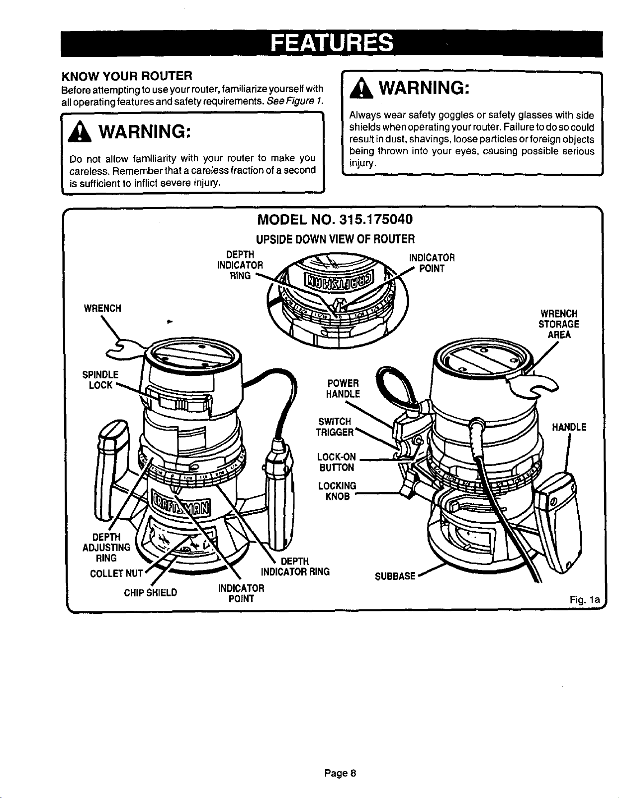
KNOW YOUR ROUTER
Before attempting to use yourrouter, familiarize yourself with
all operating features and safety requirements. See Figure I.
WARNING:
Do not allow familiarity with your router to make you
careless. Remember that a careless fraction of a second
is sufficient to inflict severe injury.
MODEL NO. 315.175040
UPSIDEDOWN VIEW OF ROUTER
DEPTH
INDICATOR
RiNG
WARNING:
Always wear safety goggles or safety glasses with side
shields when operating your router. Failure to do so could
result indust, shavings, loose particles or foreign objects
being thrown into your eyes, causing possible serious
injury.
INDICATOR
POINT
WRENCH
SPINDLE
DEPTH
ADJUS_NG
RING
COLLETNUT'
CHIPSHIELD
INDICATOR
POINT
SWITCH
BUTTON
LOCKING
DEPTH
INDICATORRING
WRENCH
STORAGE
AREA
POWER
HANDLE
HANDLE
KNOB
SUBBASE
Fig. la
Page 8
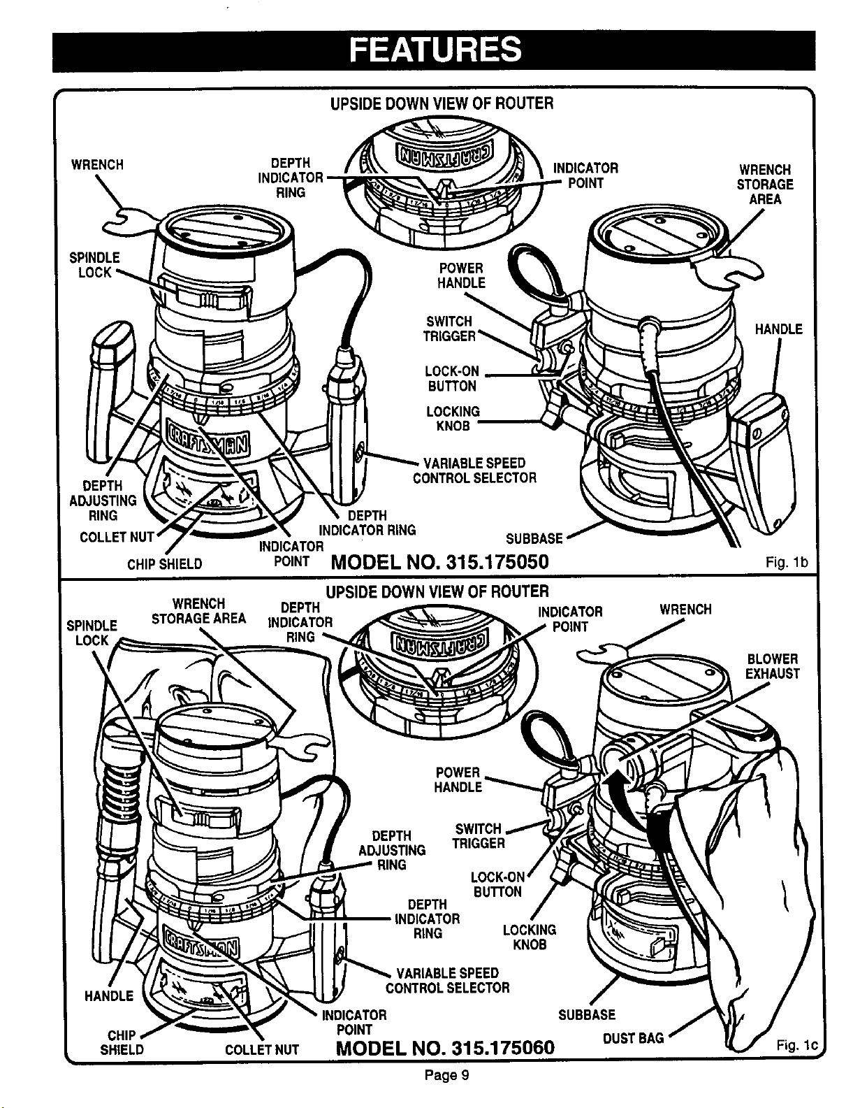
UPSIDE DOWNVIEW OF ROUTER
WRENCH
SPINDLE
DEPTH
ADJUSTING
RING
CHIPSHIELD
DEPTH
RING
POWER
HANDLE
SWITCH
TRIGGER_
LOCK-ON
BUTTON
LOCKING
KNOB
/ARIABLESPEED
CONTROLSELECTOR
DEPTH
INDICATORRING
INDICATOR SUBBASE
INDICATOR
POINT MODEL NO, 315.175050
POINT
WRENCH
STORAGE
AREA
HANDLE
Fig, 1b
WRENCH
SPINDLE STORAGEAREA
UPSIDE DOWNVIEW OF ROUTER
DEPTH INDICATOR
INDICATOR POINT
RING
WRENCH
BLOWER
MODEL NO. 315.175060
Page 9
 Loading...