

Page 1
612547-480
SEARS
OWNERS
MANUAL
MODEL NO.
315.109240
CAUTION"
Read Rules for
Safe Operation
and Instructions
Carefully
SAVE THIS
MANUAL FOR
FUTURE REFERENCE
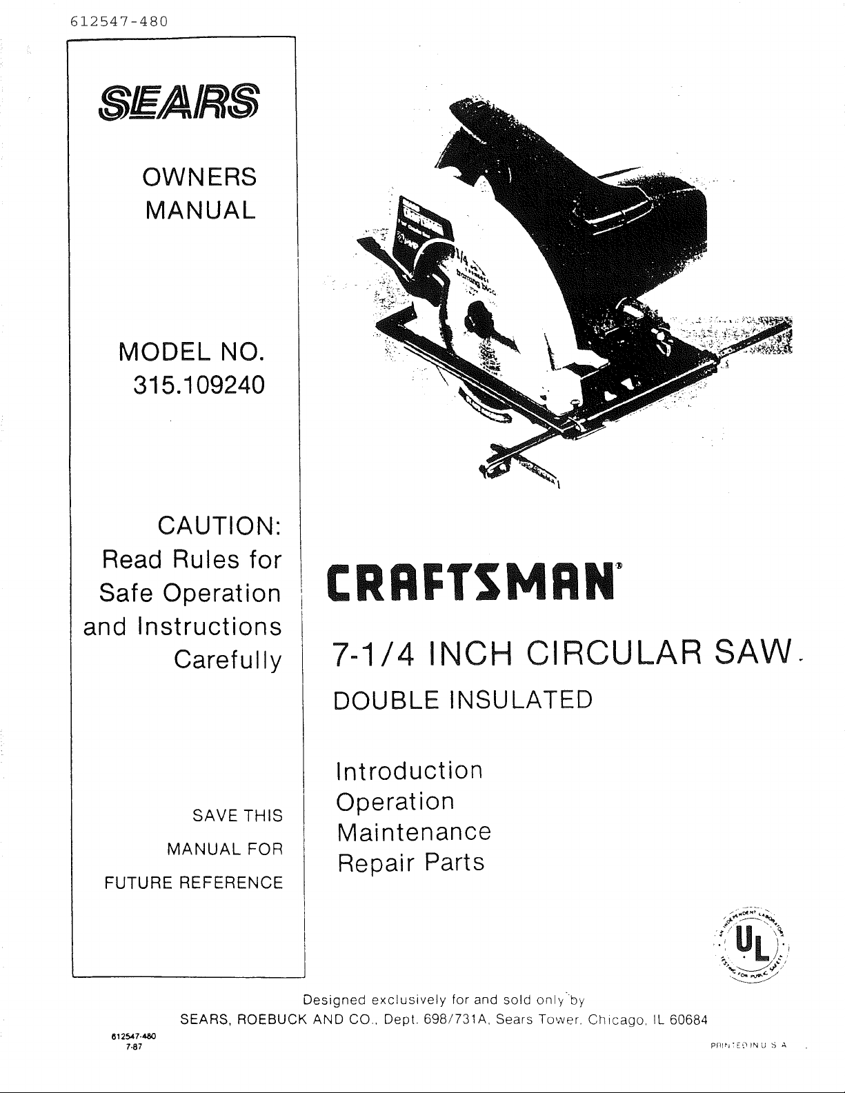
7-1/4 INCH CIRCULAR SAW.
DOUBLE INSULATED
Introduction
Operation
Maintenance
Repair Parts
8125.47-480
7-87
Designed exclusively for and sold onlyby
SEARS, ROEBUCK AND CO., Dept. 698/731A, Sears Tower. Chicago, IL 60684
pf]I_'I:EOPNU S A
Page 2
FULL ONE YEAR WARRANTY ON CRAFTSMAN CIRCULAR SAW
If this Craftsman Circular Saw fails to give complete satisfaction within one yearTff_o-_w-thedate of
purchase, RETURN IT TO THE NEAREST SEARS STORE THROUGHOUT THE UNITED STATES and
Sears will repair it, free of charge.
If this circular saw is used for commercial or rental purposes this warranty applies for only 90 days
from the date of purchase.
This warranty gives you specific legal rights, and you may also have other rights which vary from
state to state.
SEARS, ROEBUCK AND CO.
DEPT. 698/731A
SEARS TOWER
CHICAGO, IL 60684
INTRODUCTION
DOUBLE INSULATION is a concept in safety, in
electric power tools, which eliminates the need for
the usual three wire grounded power cord and
grounded supply system. Wherever there is electric
current in the tool there are two complete sets of in-
sulation to protect the user. All exposed metal parts
are isolated from the internal metal motor com-
ponents with protecting insulation.
RULES FOR SAFE OPERATION
READ ALL INSTRUCTIONS
1. KNOW YOUR POWER TOOL m Read owner's manual carefully. Learn its
applications and limitations as well as the specific potential hazards related to
this tool.
2. GUARD AGAINST ELEC_'RICAL SHOCK BY PREVENTING BODY CONTACT
WITH GROUNDED SURFACES. For example: Pipes, radiators, ranges,
refrigerator enclosures.
3. KEEP GUARDS IN PLACE and in working order. Never wedge or tie lower blade
guard open. Check operation of lower blade guard before each use. Do not use
if lower blade guard does not close briskly over saw blade. WARNING: IF SAW
IS DROPPED, LOWER BLADE GUARD MAY BE BENT, RESTRICTING FULL
RETURN. If lower blade guard becomes bent or damaged, replace it before
reuse.
4. KEEP WORK AREA CLEAN. Cluttered areas and benches invite accidents.
5. AVOID DANGEROUS ENVIRONMENT. Don't use power tool in damp or wet
locations or expose to rain. Keep work area well lit.
6. KEEP CHILDREN AWAY. All visitors should wear safety glasses and be kept a
safe distance from work area. Do not let visitors contact tool or extension cord.
7. STORE IDLE TOOLS. When not in use, tools should be stored in a dry, high or
locked-up place -- out of the reach of chiidren.
8. DON'T FORCE TOOL. It will do the job better andsafer at the rate for which it
was designed.
IMPORTANT -- Servicing of a tool with double in-
sulation requires extreme care and knowledge of the
system and should be performed only by a qualified
service technician. For service we suggest you
return the tool to your nearest Sears Store for repair.
Always use original factory replacement parts when
servicing.
Page 2
Page 3

Lheavy
t usea
loving
doors.
nask if
,t from
;ded to
Jot use
or best
anging
anging
:d.
to see
it on.
ger on
)nly ex-
marked
lg _and
Jes. Do
ove cut
N OFF.
. motor
at your
Always
roleum-
Do not
qer part
aperate
moving
qer con-
_maged
r.
defec-
IPPORT
_tion re-
d on the
Page 4
RULES FOR SAFE OPERATION (Continued)
WARNING: ALWAYS RAISE THE LOWER BLADE GUARD WLT_._I';I]'H E HANDLE
31.
TO AVOID SERIOUS INJURY. See Figure 14, Page 10.
GUARD AGAINST KICKBACK. See Pages 7 and 8.
32.
33.
BEFORE MAKING A CUT, BE SURE THE DEPTH AND BEVEL ADJUSTMENTS
ARE TIGHT.
34.
DO NOT USE BLADES WITH INCORRECT SIZE HOLES. Never use blade
washers or bolts that are defective or incorrect. The maximum blade capacity of
your saw is 7-1/4" diameter.
35.
Inspect for and remove all nails from lumber before cutting.
36.
DRUGS, ALCOHOL, MEDICATION. Do not operate tool while under the
influence of drugs, alcohol, or any medication.
WEAR HEARING PROTECTION DURING EXTENDED PERIODS OF OPERATION.
37.
SAVE THESE INSTRUCTIONS. Refer to them frequently and use them to
38.
instruct third party users. If you loan someone this tool, loan them these
instructions also.
b --
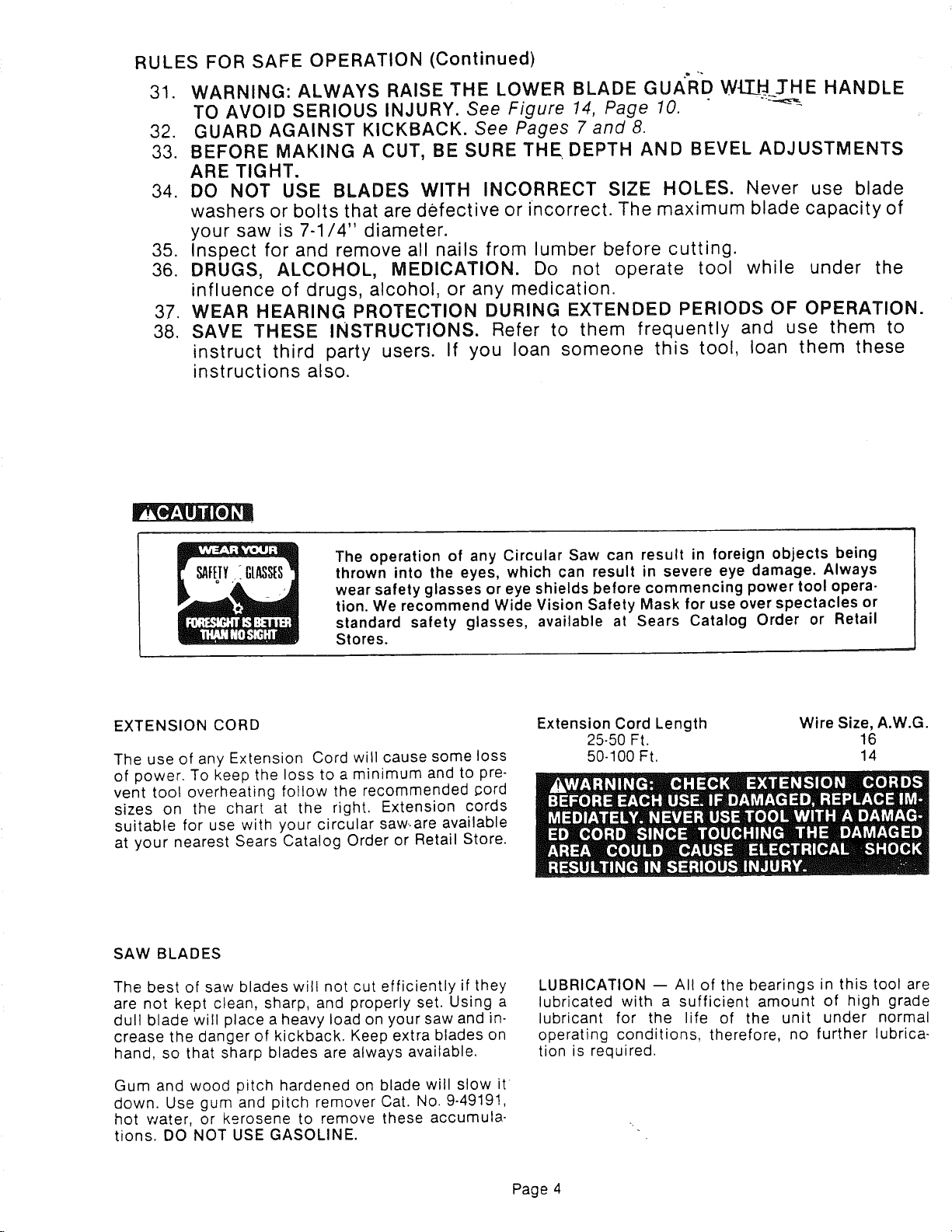
The operation of any Circular Saw can result in foreign objects being
thrown into the eyes, which can result in severe eye damage. Always
wear safety glasses or eye shields before commencing power tool opera-
tion. We recommend Wide Vision Safety Mask for use over spectacles or
standard safety glasses, available at Sears Catalog Order or Retail
Stores.
EXTENSION CORD
The use of any Extension Cord will cause some loss
of power. To keep the loss to a minimum and to pre-
vent tool overheating follow the recommended cord
sizes on the chart at the right. Extension cords
suitable for use with your circular saw-are available
at your nearest Sears Catalog Order or Retail Store.
SAW BLADES
The best of saw blades will not cut efficiently if they
are not kept clean, sharp, and properly set. Using a
dull blade will place a heavy load on your saw and in-
crease the danger of kickback. Keep extra blades on
hand, so that sharp blades are always available.
Extension Cord Length Wire Size, A.W.G.
25-50 Ft. 16
50-100 Ft. 14
LUBRICATION -- All of the bearings in this tool are
lubricated with a sufficient amount of high grade
lubricant for the life of the unit under normal
operating conditions, therefore, no further lubrica-
tion is required.
Gum and wood pitch hardened on blade will slow it
down. Use gum and pitch remover Cat. No. 9-49191,
hot water, or kerosene to remove these accumula-
tions. DO NOT USE GASOLINE.
Page 4
Page 5
OPERATION
FEATURES
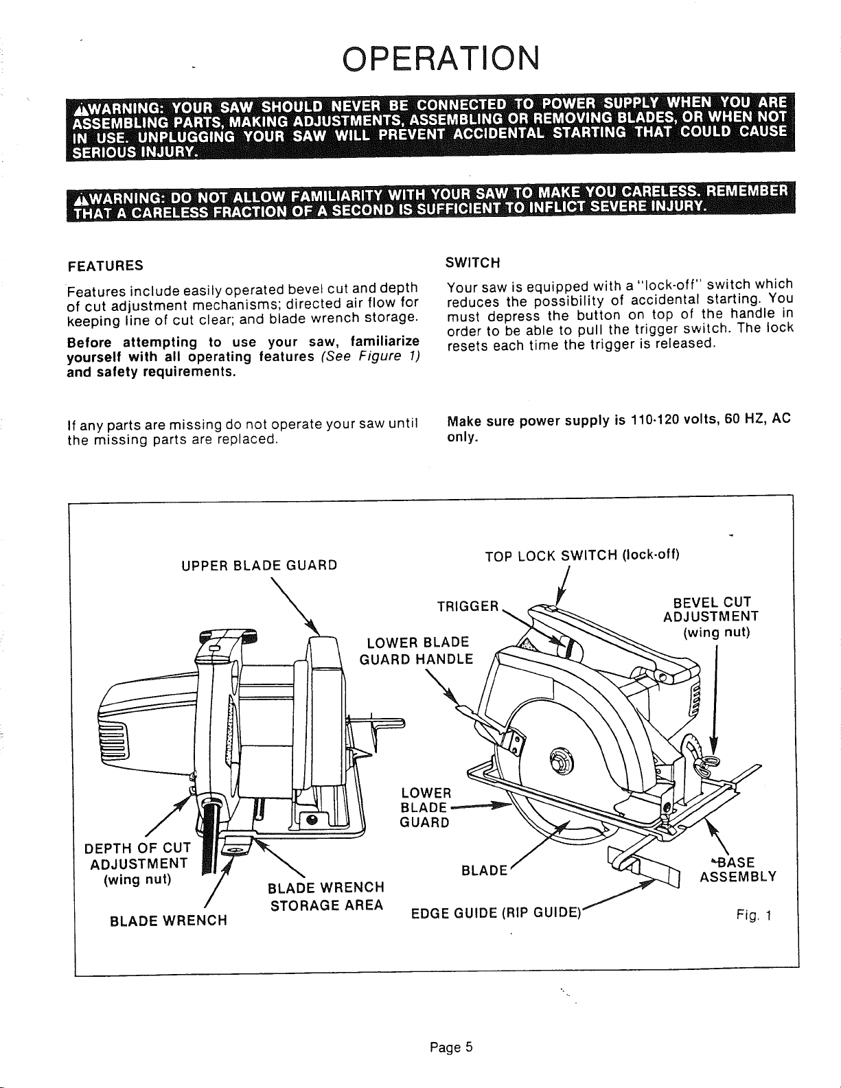
Features include easily operated bevel cut and depth
of cut adjustment mechanisms; directed air flow for
keeping line of cut clear; and blade wrench storage.
Before attempting to use your saw, familiarize
yourself with all operating features (See Figure 1)
and safety requirements.
If any parts are missing do not operate your saw until
the missing parts are replaced.
UPPER BLADE GUARD
LOWER BLADE
GUARD HANDLE
SWITCH
Your saw is equipped with a "lock-off" switch which
reduces the possibility of accidental starting. You
must depress the button on top of the handle in
order to be able to pull the trigger switch. The lock
resets each time the trigger is released.
Make sure power supply is 110.120 volts, 60 HZ, AC
only.
TOP LOCK SWITCH (lock-off)
TRIGGER
BEVEL CUT
ADJUSTMENT
(wing nut)
DEPTH OF CUT
ADJUSTMENT
(wing nut)
BLADE WRENCH
BLADE WRENCH
STORAGE AREA
LOWER
BLADE
GUARD
BLADE
EDGE GUIDE (RIP GUIDEI
Page 5
"-BASE
ASSEMBLY
Fig. 1
Page 6

OPERATION
TO ASSEMBLE BLADE
1. UNPLUG YOUR SAW.
2. Remove blade wrench from storage area, See
Figure 2,
3. Position your saw on end of motor housing and
remove blade screw. NOTE: Turn blade screw
counterclockwise to remove.
4. Remove spring washer and "D" washer.
BLADE WRENCH LOWER BLADE
STORAGE GUARD HANDLE
SPINDLE
OUTER BLADE
"D" WASHER
SPRING
WASHER
LOWER INNER
BLADE BLADE
GUARD WASHER
BLADE
BLADE
.
Fit saw blade inside blade guard and onto spindle.
NOTE: The saw teeth point upward at the front of
saw.
,
Replace "D" washer and spring washer. NOTE:
"Cupped" side of spring washer goes against
outer blade "D" washer. See Figure 2,
,
Replace blade screw and tighten until spring
washer is flattened. NOTE: Turn blade screw
clockwise to tighten.
.
Return blade wrench to storage area. NOTE:
Always place angled portion of blade wrench up
as shown in figure 2.
TO REMOVE BLADE
1. UNPLUG YOUR SAW.
2. Remove blade wrench from storage area. See
Figure 2.
3. Place your saw on a piece of scrap wood as shown
in figure 3 with the blade teeth embedded in the
wood.
,
Turn blade screw counterclockwise and remove.
5,
Remove spring washer, "D" washer, and blade.
Before replacing blade, wipe a drop of oil onto
washers where they contact blade.
,
Return blade wrench to storage area. NOTE:
Always place angled portion of blade wrench up
as shown in figure 2.
OUTSIDE OF SPRING WASHER
CUPPED SIDE AGAINST
OUTER BLADE "D" WASHER
Fig. 2
TOP LOCK SWITCH (lock-off)
LOWER BLADE
GUARD HANDLE
/
BLADE
WRENCH
X
BLADE SCREW
Fig. 3
Page 6
Page 7

OPERATION
BLADE GUARD SYSTEM
The lower blade guard attached to your circular saw
is there for your protection and safety. It should
never be altered for any reason. If it becomes damag-
ed, do not operate your saw until the damage has
been repaired or replaced. Always leave guard in
operating position when using your saw.
When sawing through 'work, lower
blade guard does not cover blade on underside of
work. See Figure 4.
Since blade is exposed on underside of work, keep
hands and fingers away from cutting area. Any part
of your body coming in contact with moving blade
will result in serious injury. Never use saw when
guard is not operating correctly. Guard should be
checked for correct operation before each use.
NOTE: The guard is operating correctly when it
moves freely and readily returns to the down posi-
tion. If you drop your saw, check the lower blade
guard for damage to all depth settings before reuse.
KICKBACK
THE BEST GUARD AGAINST KICKBACK IS TO
AVOID DANGEROUS PRACTICES.
LOWER BLADE GUARD
IS IN UP POSITION WHEN
MAKING CUT
T
BLADE EXPOSED ONE WHOLE Fig. 4
TOOTH ON UNDERSIDE OF WORK
Kickback occurs when the blade stalls rapidly and
the saw is driven back towards you.
RELEASE SWITCH IMMEDIATELY IF BLADE BINDS
OR SAW STALLS. See Figure 5. Kickback could
cause you to lose control of your saw. Loss of con-
trol can lead to serious injury.
KICKBACK IS CAUSED BY:
1. Incorrect blade depth setting. See Figure 5.
2. Sawing into knots or nails in work.
3. Twisting blade while making a cut.
4. Making a cut with adull, gummed up, or improper-
ly set blade.
5. Incorrectly supporting work. See Figure 6.
6. Forcing a cut.
7. Cutting warped or wet lumber.
8. Tool misuse or incorrect operating procedures.
TO LESSEN THE CHANCE OF KICKBACK:
1. Always keep the correct blade depth setting
the correct blade depth setting for all cuts has one
whole tooth projected below the material to be
cut. (For carbide-tipped blades, only one-half of a
tooth). See Figure 4.
2. Inspect the work for knots or nails before begin-
ning a cut. Never saw into a knot or nail.
BLADE SET L_j_
TOO D EEp _.,=,,,==..,_ Fig. 5
RIGHT
WRONG
Fig. 6
Page 7
Page 8

OPERATION
TO LESSEN THE CHANCE OF KICKBACK (Cont'd.)
.
Make straight cuts. Always use a straight edge
guide when rip cutting. This helps prevent
twisting the blade in the cut.
.
Always use clean, sharp, and properly .set blades.
Never make cuts with dull blades.
.
To avoid pinching the blade, support the work
properly before beginning a cut. The right and
wrong ways to support large pieces of work are
shown in figure 6.
6. When making a cut use steady, even pressure.
Never force cuts.
7. Do not cut warped or wet lumber.
8. Always hold your saw firmly with both hands and
keep your body in a balanced position so as to
resist the forces of kickback should it occur.
WHEN USING YOUR SAW ALWAYS STAY ALERT
AND EXERCISE CONTROL. DO NOT REMOVE YOUR
SAW FROM WORKPIECE WHILE THE BLADE IS
MOVING.
DEPTH OF CUT ADJUSTMENT
Always keep correct blade depth setting. The correct
blade depth setting for all cuts has one whole tooth
projecting below the material to be cut. (For carbide-
tipped blades, only one-half of a tooth). More blade
depth will increase the chance of kickback and
cause the cut to be rough.
TO ADJUST BLADE DEPTH
1. UNPLUG YOUR SAW.
/
BASE
ASSEMBLY
WING NUT
Fig. 7
RIGHT
Fig. 8
2. Loosen wing nut. See Figure 7.
3. Hold base flat against the work and raise or lower
saw until the required depth is reached.
4. Tighten wing nut securely.
STARTING A CUT
KNOW THE RIGHT WAY TO USE YOUR SAW. See
Figure 8.
NEVER USE YOUR SAW AS SHOWN IN FIG. 9.
NEVER PLACE YOUR HAND ON THE WORKPIECE
BEHIND YOUR SAW WHILE MAKING A CUT.
WRONG
Fig. 9
Page 8
Page 9

OPERATION
STARTING A CUT (Cont'd)
TO HELP MAINTAIN CONTROL:
1. Always support your work near the cut.
2. Support your work so the cut will be on your right.
3. Clamp your work so it will not move during the
cut.
Place your work with its good side down. NOTE: The
good side is the side on which appearance is impor-
tant.
Before beginning a cut, draw a guide line along the
desired line of cut. Then place front edge of base on
that part of your work that is solidly supported. See
Figure 10.
TOP LOCK SWITCH (lock.off)
RIGHT
Fig. 10
NEVER PLACE YOUR SAW ON THAT PART OF THE
WORK THAT WILL FALL OFF WHEN THE CUT IS
MADE. See Figure 11.
Keep the cord away from cutting area. ALWAYS
place the cord to prevent it from hanging up on the
work while making a cut.
_lf the cord hangs up on the work during
a cut, release the switch trigger immediately. Unplug
your saw and reposition the cord to prevent it from
hanging up again.
_Using your saw with a damaged cord
could result in serious injury or death. If the cord has
been damaged, have it replaced before using your
saw again.
Hold your saw firmly with both hands. See Figure 10.
Push the lock-off button down and squeeze the
switch trigger. NOTE: The lock-off button is located
on top of the handle. ALWAYS LET THE BLADE
REACH FULL SPEED, THEN GUIDE YOUR SAW IN-
TO THE WORK.
WRONG
Fig. 11
REMEMBER:
When sawing through work, the lower blade guard
does not cover the blade, exposing it on the under-
side of work. Keep your hands and fingers away from
cutting area. Any part of your body coming in con-
tact with the moving blade will result in serious
injury.
After you complete your cut release the trigger and
allow the blade to come to a complete stop. DO NOT
REMOVE YOUR SAW FROM WORKPIECE WHILE
THE BLADE IS MOVING.
When making a cut use steady, even pressure. Forc-
ing causes rough cuts, could shorten the life of your
saw and could cause "kickback."
_When lifting your saw from the work
the blade is exposed on the underside of your saw
until the lower blade guard closes, Make sure lower
blade guard is (}tosed before setting your saw down
on work surface.
Page 9
Page 10

OPERATION
TO CROSS CUT OR RIP CUT
When making a cross cut or rip cut, align your line of
cut with the outer edge of the notch in the saw base
as shown in figure 12. Since the thickness of blades
vary, always make a trial cut in scrap material along a
guideline to determine how much, if any, the
guideline must be offset to produce an accurate cut.
NOTE: The distance from the line of cut to the
guideline is the amount you should offset the
guideline.
RIP GUIDE
Use a rip guide when making rip cuts up to five
inches wide. It helps prevent the blade from twisting
in a cut. The blade twisting in a cut causes kickback.
If needed, Rip Guide Cat. No. 9 27679 is available at
your Sears Catalog Order or Retail Store.
TO ASSEMBLE RIP GUIDE
1. UNPLUG YOUR SAW.
, ---=_
TOP VIEW OF SAW FRONT OF SAW
u ll !i
NOTCH IN SAWiBASE r J
#
ALIGN OUTER EDGE OF NOTCH IN SAW
BASE WITH LINE OF CUT AS SHOWN
WHEN MAKING CROSS CUTS OR RIP CUTS
/
GUIDELINE
Fig. 12
2. Place rip guide through holes in saw base as
shown in figure 13.
3. Adjust rip guide to the length needed for the cut.
4. Tighten screw securely.
When using a rip guide, hold the face of the rip guide
firmly against the edge of work. This makes for a true
cut without pinching the blade. The guiding edge of
work must be straight for your cut to be straight. Use
caution to prevent the blade from binding in the cut.
TO POCKET CUT
With the bevel setting adjusted to zero, swing the
lower blade guard up using the lower blade guard
handle.
TOP VIEW RIP GUIDE
OF SAW
SCREW
LOWER
BLADE
GUARD
PLACE RIP
GUIDE THRU
HOLES
Fig. 13
LOWER BLADE
GUARD HANDLE
While holding lower blade guard by the handle, firm-
ly rest the front of the base flat against the
workpiece with the rear of the base raised so the
blade does not touch the work. See Figure 14. Push
the lock-off button down and squeeze the switch
trigger. ALWAYS LET THE BLADE REACH FULL
SPEED THEN SLOWLY LOWER BLADE INTO THE
WORK UNTIL BASE IS FLAT AGAINST WORK.
POCKET CUT
Fig. 14
Page 10
Page 11

OPERATION
TO POCKET CUT (Cont'd.)
After you complete your cut release the trigger and
allow the blade to come to a complete stop. DO NOT
REMOVE YOUR SAW FROM WORKPIECE WHILE
THE BLADE IS MOVING.
Corners may then be cleaned out with a hand saw or
sabre saw.
TO BEVEL CUT
The angle of cut of your saw may be adjusted to any
desired setting between zero and 45 degrees. There
is a notch in the saw base to help you line up the
blade with the line of cut. See Figure 15. Align your
line of cut with the inner edge of the notch in the saw
base when making full 45 degree bevel cuts. Since
the thickness of blades vary and different angles re-
quire different settings, always make a trial cut in
scrap material along a guideline to determine how
much you should offset the guideline on the board to
be cut.
When making a bevel cut hold your saw firmly with
both hands as shown in Figure 16. Rest the front
edge of the base on the work. Push in the lock-off
button and squeeze the switch trigger. ALWAYS LET
THE BLADE REACH FULL SPEED, THEN GUIDE
YOUR SAW INTO THE WORK.
TOP VIEW
OF SAW
MOTOR
ISING
BEVEL SCALE
WING
NOTC[ IN _
SAW BASE
GUIDELINE
After you complete your cut release the trigger and
allow the blade to come to a complete stop. DO NOT
REMOVE YOUR SAW FROM WORKPIECE WHILE
THE BLADE IS MOVING.
TO ADJUST BEVEL SETTING
1. UNPLUG YOUR SAW.
2. Loosen wing nut. See Figure 15.
3. Raise motor housing end of saw until you reach
the desired angle setting on bevel scale. See
Figure 15.
4. Tighten wing nut securely.
ALIGN INNER EDGE OF NOTCH IN SAW
BASE WITH LINE OF CUT AS SHOWN
WHEN MAKING 45 ° BEVEL CUTS
Fig. 15
LOWER BLADE
GUARD
,.,.Fig. 16
Page 11
Page 12

MAINTENANUI=
WHEN SERVICING USE ONLY IDENTICAL REPL'/_CEMENT PARTS
POWER CORD OR SWITCH REPLACEMENT
1. UNPLUG YOUR SAW.
2. Remove screws and wing nut securing handle
cover. See Figure 17.
3. Carefully lift handle cover away from tool.
4. Note the locations of all lead wiring inside the
handle and how each connection has been made.
IMPORTANT: When the new cord or switch is in-
stalled, identical connections must be made.
5. Remove the lead wires from the switch by insert-
ing a 1/32" diameter pin or nail into each switch
lead receptacle and pull the lead wires as shown
in Figure 16. This will release the wires. Remove
the pin or nail with a twisting motion.
6. To replace lead wires, push each lead wire into its
proper receptacle. NOTE: Be sure to push lead
wires into switch as far as possible.
7. Locate the switch in the handle and place all wir-
ing so it cannot be pinched or contact screws
when handle cover is replaced.
8. Replace handle cover, screws, and wing nut.
9. Tighten screws and wing nut securely.
HANDLE
COVER
SCREWS
WING NUT /
SCREW
1/32" DIAMETER
NAIL OR PIN
Fig. 17
GENERAL
Only the parts shown on parts list, page 15, are in-
tended to be repaired or replaced by the customer.
All other parts represent an important part of the
double insulation system and should be serviced on-
ly by a qualified s_rvice technician.
Avoid using solvents when cleaning plastic parts.
Most plastics are susceptible to various types of
commercial solvents and may be damaged by their
use. Use clean cloths to remove dirt, carbon dust,
etc.
THE FOLLOWING RECOMMENDED ACCESSORIES WERE AVAILABLE AT THE TIME THIS MANUA
WAS PRINTED.
Cord Lock _ 2595)
Carrying Case (914702)
Rip Guide (9_27679)
50' 14 A.W.G. Ext. Cord (9 5821)
71/4Saw Blade _ 32303)
71/4Saw Blade _ 32423)
71/4Saw Blade _ 32494)
71/4Saw Blade _ 32564)
100' 14 A.W.G. Ext. Cord (9 83508)
When electric tools are used on fiberglass boat
sports cars, etc., it has been found that they are sut
ject to accelerated wear and possible prematut
failure, as the fiberglass chips and grindings a_
highly abrasive to bearings, brushes, commutato
etc. Consequently it is not recommended that th
tool be used for extended work on any fibergla_
material. During any use on fiberglass it is extremel
important that the tool is cleaned frequently by blov
ing with an air jet. ALWAYS WEAR SAFET
GLASSES, DUST MASK, OR EYESHIELDS BEFOR
BEGINNING POWER TOOL OPERATION OR BLOV
ING DUST.
71/4Saw Blade _ 32664)
71/4Saw Blade _ 32444)
71/4Saw Blade _ 32526)
71/4Saw Blade (932518)
7l/;_Saw Blade _ 32489)
_The use of attachments or accessories not listed above might be hazardous.
Page 12
Page 13

MAI NTENANCE (Cont'd.)
TO CLEAN SAWDUST FROM LOWER BLADE
GUARD
Periodically sawdust will accumulate behind the
lower blade guard causing it to be clogged. This
clogging could prevent guard from moving freely and
readily returning to the down position after use.
1. UNPLUG YOUR SAW.
2. Remove saw blade from your saw. See "To
Remove Blade" instructions on page 6. Also
remove inner blade washer.
3. Remove pan head screw and bumper. See Figure
18.
4. Remove wing nut, lower depth of cut on base
assembly until carriage bolt can be removed, then
remove carriage bolt. Rotate base assembly until
it clears lower blade guard.
5. Using a 3/16" flat blade screwdriver or needle-
nose pliers, remove retaining ring from blade
guard support. ALWAYS WEAR SAFETY
GLASSES OR EYESHIELDS.
TO REASSEMBLE
See Figure 18.
.
Check torsion spring and make sure it has not
been bent or damaged. Replace if necessary.
2.
Place lower blade guard in normal operating posi-
tion and secure to blade guard support with retain-
ing ring. NOTE: Retaining ring can easily be in-
stalled by spreading it apart similar to a spring and
rolling around the groove on blade guard support.
See Figure 18.
.
Rotate lower blade guard approximately 1-1/2
turns clockwise until tension on torsion spring is
tight. NOTE: The hook on torsion spring must be
aligned with tab on spring retainer before tension
can be applied to spring. See Figure 18. If lower
blade guard does not become tight, the hook on
tension spring is not engaged with tab on blade
guard. Do not attempt to use your saw until lower
blade guard has the proper amount of tension.
.
Reposition base assembly, then replace carriage
bolt, wing nut, bumper, and screw.
5.
Reassemble saw blade. See "To Assemble Blade"
instructions on Page 6.
6. Remove lower blade guard from your saw and
clean. Also clean blade guard support area. NOTE:
When cleaning use an air hose, clean soft cloth or
brush.
BLADE GUARD
SUPPORT
',,___ SC R EW
/
WING NUT
BASE ASSEMBLY
CARRIAGE BOLT /
HOOK ON TORSION SPRING
BUMPER
LOWER
BLADE
GUARD
SPRING
RETAINER
TAB
RETAINING
RING
INNER BLADE WASHER
OUTER BLADE
"D" WASHER
BLADE
Page 13
SPRING WASHER
BLADE SCREW
Fig. 18
Page 14

Page 15

Page 16

OWNERS
MANUAL
7-1/4 INCH CIRCULAR SAW
DOUBLE INSULATED
SERVICE
MODEL NO.
315.109240
HOW TO ORDER
REPAIR PARTS
Now that you have purchased your Circular Saw,
should a need ever exist for repair parts or service,
simply contact any Sears Service Center and most
Sears, Roebuck and Co. stores. Be sure to provide
all pertinent facts when you call or visit.
The model number of your Circular Saw will'be
found on the plate attached to the motor housing.
WHEN ORDERING REPAIR PARTS, ALWAYS GIVE
THE FOLLOWING INFORMATION:
• PART NUMBER ,, PART DESCRIPTION
MODEL NUMBER _ NAME OF ITEM
315.109240 Circular Saw
All parts listed may be ordered from any Sears Ser-
vice Center and most Sears stores.
If the parts you need are not stocked locally, your
order will be electronically transmitted to a Sears
Repair Parts Distribution Center for handling.
SEARS, ROEBUCK AND CO., Dept. 698/731A, Sears Tower, Chicago, IL 60684
 Loading...