

Page 1

(6)- (110 SOURCE) DRYER MOTOR KIT #279787.
Page 2
INSTALLATION AND WIRING INSTRUCTIONS
for Pluggable Motor Replacement - _7q'1ul
ThlsKitContains:
I Motor Assembly 3 • _ _"_" _ _/'
2 Vg'FemaleTem!lnals(Insulated) 3 3 q E q_
I Sheet, I_slr_oUon _ _€_-1 8
NOTETOTHEINSTALLER: Thlsm tarkitlsenButho zedFSP_rvicereplscemerltparlloryourapplloation.
The motor m this kit may or mw not be Identical to your old motor. If your culTentmotor has the pluggable.
motor marltch, replaoe the serv|c.e..,motor in the same manner as you removed your dele_llve motor. If
your defeolive mof_r has the switch where the w[m lead from the main harness eannects to the motor
I" ° "L
s_tch Indivklually, carefully follow Instructions below-- ......
Electrical Shock Hazard
OLsoonneat power before
_;ervi_ng.
Failure to do so eould result In
I I ii1
Potent|al Rre Hazard and/or
Nulsanoe "l'dpptng of Motor Protector
DO NOT under any oiroumstance attempt
to remove or replace the motor 8witoh
from this p|uggable service motor. The
swituh is a non..serviceable.bomponent.
Failure to do so oould result in fire, serious
injury or death.
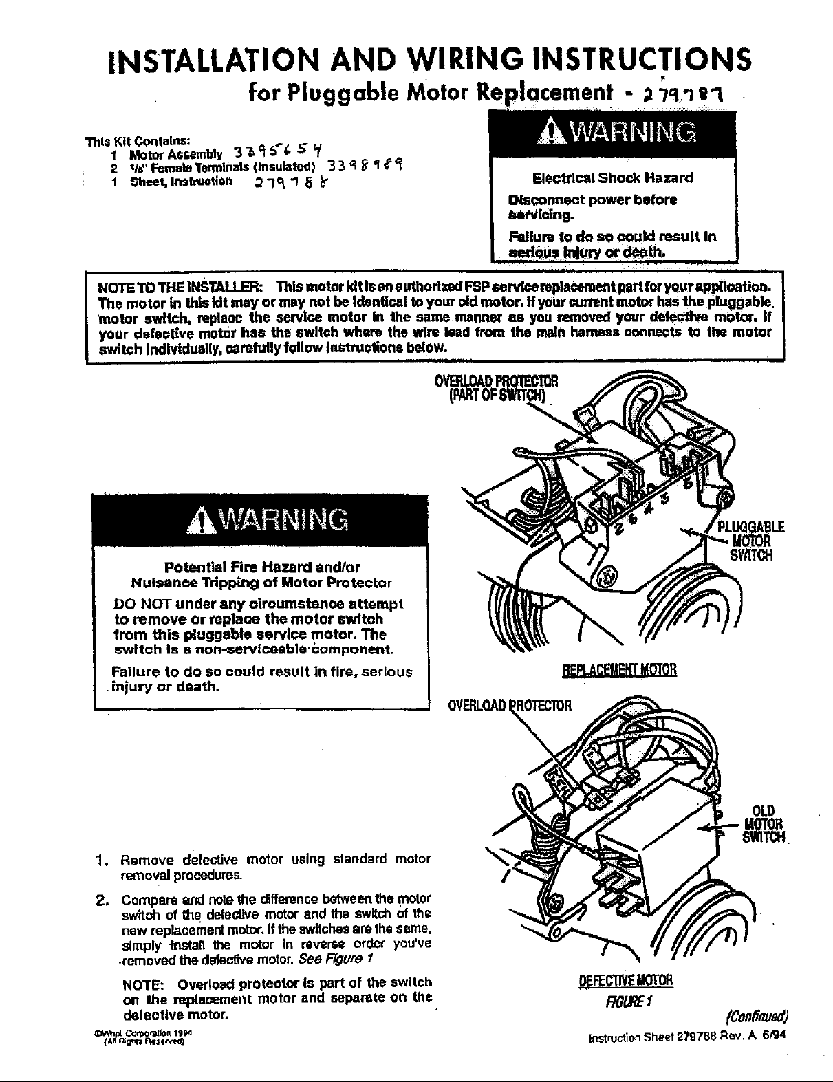
1. Remove defective motor using standard motor
removal proaedures
2. Compare and no_ethe differencebetween the motor
switch of fire delective motor and the switch of the
new replaoement motor, ffthe switchesare thesame,
simply -instal! the motor In reverse order you've
-removed the defectivemotor. See Figure 1.
NOTE: Overload proteotor Is part of the switch
on the replaoBrnent motor and separate on the
deleotive motor.
Corpo_to. 1111H
OVERLOADI
OLD
0EFECllVEg01_
P,0/JqE/
InstrucSonSheet279788Rev.A 6/94
Page 3

34 13o Connect thet_ack(6M)wke leadOntothelie" terminal
Positionmotoras shown in Figure2. Notethe location
of the motor switch.Secure motor to bradder with the
marked "6" onthe motorswitch_,-'_eFigure.3.
origim_motor damps,
BLACK "fELLOW,
.yVIRING INSTRUCTIONS
NOTE: Read =rid follow Instructions carefully. If the
unit you are replacing the motor on has the option
which included the momentary switches for the drum,
proceed to section title WlRIN_3JNSTRUCTIONS---
MOMENTARY SWITCH APPUCATIONt otherwise,
proceed to s_ep 4.
_,_ Connect the blue (4M) wire lead from the broken belt
switch to the vacant terminal located on the ba_ of
the overload prote_or of _he motor switch. See
Figure 3
5o ConneCt the red (1M) wire lead. to 'Jle _/4_ terminal
marked "1" onthe motor switch. 'See Figure 3.
6o Connect the red (2M} wire lead to the _/4"terminal
rr_xked "2" on the motor sv#ftch.See _Tgure3.
"7. Connect the yellow (BK2) wire lead to the vacant
termth_J onthe broken belt switch. See Figure 3.
8. 'To connect the black (6M} wire lead and the while
(5M) wire lead to the motor switch, you must replace
the _/4"female terminalswiththe 1/8"insulated female
_erminals includedwith the replacement motor.
9_ Cut _e _14'female terminal from the black (6M) and
white (SM) wire leads as close to the terminaJ as
possible with wire eL,tiers.
! O_Strip wires back approxim_,tely _14elan inch.
t"_[h barrel c_mpers, crimp _!_ insulated female:
terminals, ]no4t_dedwith motor, onto the w&'eleads.
RGURE3
14. Reconnectgroundwire to motor. _ee Figure 3_
"_5.All wire lead (_nnections are completeat this point.
you can now reinstall themotor andbracket assembly
into the unit.
WIRING INSTRUCTION_
MOMENTARY SWITCH APPLICATION
1_ Connect the blue (4M) wire lead from the broken belt
switchtO the vacantterminal located on the back of
the overload protector of the meter switch. See
Figure 4.
2_
Connect the red (1M} wire lead to the _/4°tem]ina!
m_ked "I" on the motor switch. See Figure 4.
Connect the red (2M) wire lead ta the _14"terminal
markeO "2" on the meier switch. See Figure 4.
4_
Connect the yellow (8K2) wire lead to the vacant
terminal on the broken belt switch See Figure 4.
,5.
To connect the purple (3M_ wire lead and the white
(5_'_ wire lead to the motor switch, you must replace
lll e _/4"female terrninalwith the tIs"insulated terminals
included wffhthe replacementmotor.
_f.'_TE: _ake sure ter_r_inals 8_'ecr_rr_dseeurely
_mp_aoe.
2_Connec_ the white (5M)wlre lead onto _he_/e"termi_al .
m_rked "5" on the motor sw_teh See Figure 3
27£788-A .... 2
Cut the t/_,, female terminaJ from the purple (3M) and
white (5M) wire leads as close to the terminal as
possible w_h wire cutters
Page 4

7, Strip w_ee back approximately 1/4of an indl.
8. W_h ba_el crimpers, _lmp _/*" ir_vteted female
ten_nlnal$,Inclucleclwith motor, ontothe wire leads
NOTE: Make sure terminals are crimped securely
In place.
9. Connect the white(SM)wire lead ontothe i/€ terminal
marked "5" on the motor swlte,h. See _ 4.
10. Connec_the purple_ wire !eadontothe 1M terminal
,.a'_d"_"?, the...motors_ch.seeRg_ur_e_....
11, RcconneGtgroundwire to motor. See Rgura 4.
12. All wire lead conneotlOns are complete at this polnL
You can now reln_tlhe'motor and brackete._embly
intounit.
_4
 Loading...