

Page 1
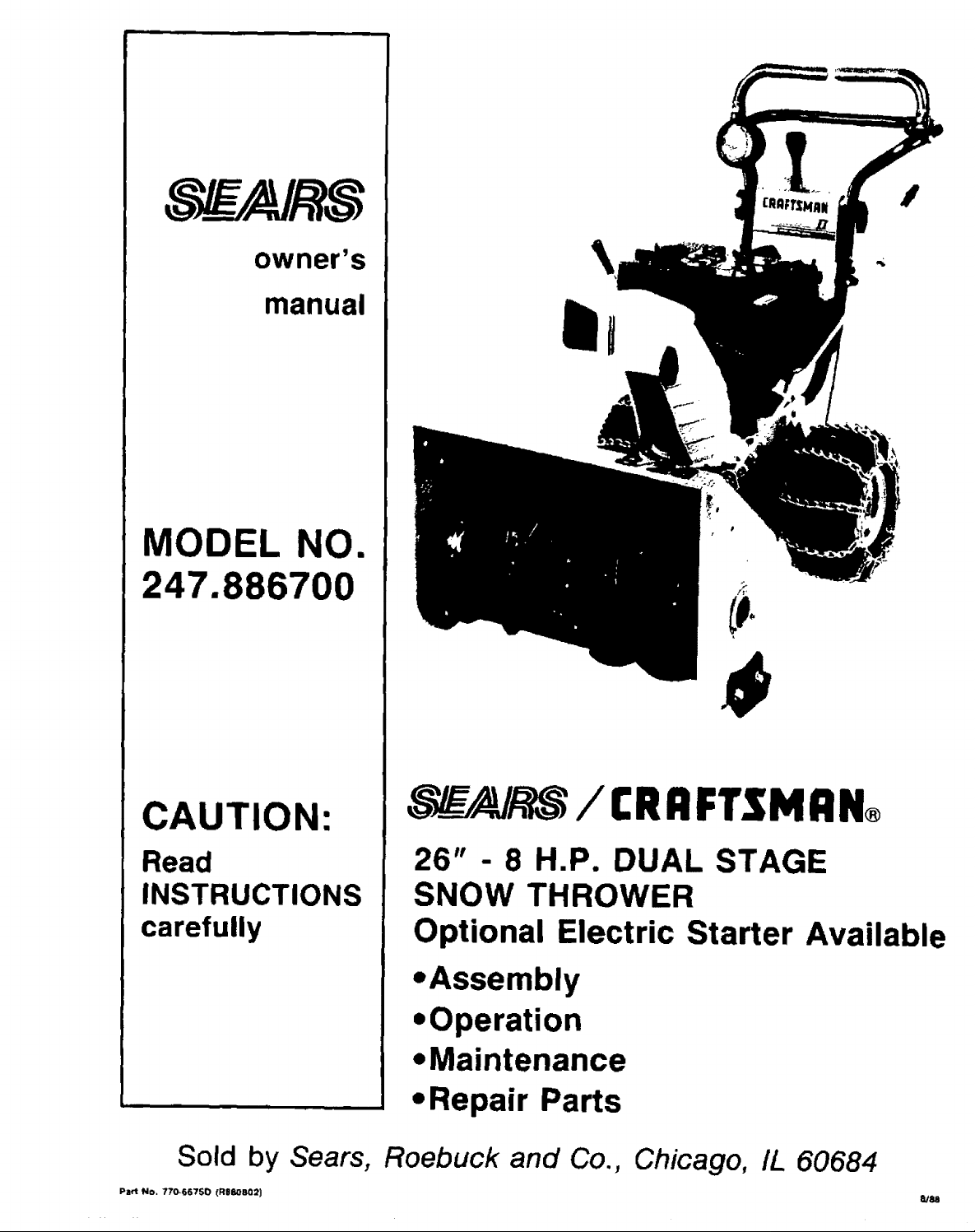
owner's
manual
MODEL NO.
247.886700
\
CAUTION:
Read
INSTRUCTIONS
carefully
Sold by Sears,
Part No. 770-66750 (RBJO802)
___/__ / CRAFTSMAN®
26" - 8 H.P. DUAL STAGE
SNOW THROWER
Optional Electric Starter Available
-Assembly
=Operation
-Maintenance
• Repair Parts
Roebuck and Co., Chicago, IL 60684
8188
Page 2
IIIIIIIIIIIz I U IIII i1 III III i . • I IIIIII UIIIIIIII
CRAFTSMAN WARRANTY
LIMITED TWO YEAR WARRANTY ON CRAFTSMAN SNOW THROWER
For two years from the date of purchase, when this Craftsman Snow Thrower :smaintained, lubricated and tuned up
according to the instructions in Ihe owner's manual, Sears will repa=r, free of charge, any defect in materia{ and
workmanship.
if this Craftsman Snow Thrower _sused for commercial or rental purposes, this warranty applies for only 90 days from
the date of purchase.
This warranty does not cover: Expendable items which become worn during normal use, such as spark plugs, tire
chains and shear pins.
Repairs necessary because el operator abuse or negligence, including bent crank-shafts and the failure to main-
lain the equipment according to the instructLons contained in the owner's manual.
WARRANTY SERVICE IS AVAILABLE BY CONTACTING THE NEAREST SERVICE CENTER/DEPARTMENT IN THE
UNITED STATES. This warranty applies only while {hfs product iS in use in the United States.
This warranty gives you specific legaI rights, and you may also have ether rights which vary from state to stale.
SEARS, ROEBUCK AND CO.
, iiiiiiiiiiiiiiiiiiiiiiiiiiiiiiiiiiiiiiIll I I
DEPT. 698/731A
SEARS TOWER
CHICAGO, IL 50684
OWNER'S INFORMATION
Record the following information about your unit so that you will be able to provide it in case of loss or theft.
DATE PURCHASED: MODEL NO./CODE: 247.886700t__
STORE WHERE PURCHASED: ADDRESS
CITY: ____. STATE: TELEPHONE:
MAINTENANCE AGREEMENT
A SEARS MAINTENANCE AGREEMENT IS AVAILABLE FOR THIS PRODUCT. CONTACT YOUR NEAREST
SEARS STORE FOR DETAILS.
TABLE OF CONTENTS
CRAFTSMAN WARRANTY ..................... 2
Page
OWNER'S INFORMATION ..................... 2
MAINTENANCE AGREEMENT ................... 2
SAFE OPERATION PRACTICES ................. 3
ASSEMBLY INSTRUCTIONS .................. 4-6
Tools Required for Assembly ............... 4
Contents of Shipping Carton .................. 4
Unpacking ........................... 4
installing the Chute Crank ............... 4, 5
Checking Adjustment of Clutch Cables ........ 5
Installing the Headlight Assembly ............. 6
Tire Pressure .......................... 6
Final Adjustments .......................... 6
OPERATING INSTRUCTIONS ................ 6-10
Engine Operating Controls .............. 6, 7
Snow Thrower Operating Controls .......... 7, 8
To Service Engine ......................... 8
To Start Engine ....................... 8, 9
Page
To Stop Engine ............................. 9
Operating the Snow Thrower ............... 9. 10
MAINTENANCE ........................... 10, 11
Maintenance Check List .................... 10
Lubrication ............................ 11
STORAGE ................................ 12
ADJUSTMENT/REPAIRS ................... 12-16
Skid Shoe Adjustment ................. 12, 13
Speed Select Lever Adjustment .............. 13
Cable Adjustment ........................ 13
Belt Replacement ...................... 13-15
Auger Shear Bolt Replacement ............ 15
Spark Plug ............................. 15
Carburetor Adjustment ..................... 16
TROUBLE SHOOTING GUIDE ................ 17
SNOW THROWER REPAIR PARTS .......... 18-25
ENGINE REPAIR PARTS ................. 26-30
HOW TO ORDER REPAIR PARTS ....... Back Cover
2
Page 3
II
IMPORrAN
SAFE OPERATION PRACTICES FOR WALK-BEHIND SNOW THROWERS
THIS SYMBOL POINTS OUT IMPORTANT SAFETY INSTRUCTIONS WHICH, IF NOT FOLLOWED COULD
ENDANGER THE PERSONAL SAFETY ANDIOR PROPERTY OF YOURSELF AND OTHERS. READ AND
FOLLOW ALL INSTRUCTIONS IN THIS MANUAL BEFORE ATTEMPTING TO OPERATE YOUR SNOW
THROWER.
To reduce the potential for any injury, comply with the following safety instructions. Failure to comply with
the instructions may result in personal injury.
TRAINING
1. Read this owner's gurde carelutly. Be thoroughly faro, liar with
the controls and proper use of the equipment. Know how to
stop the unit and disengage the controls quickly.
2. Never allow ch=ldren to operate equipment, Never allow
adults to Qperate equipment without proper instruclions
3. No one should operate this unit while intoxicated or while
taking medication that Jmpabrs the senses or react,ons.
4. Keep the area of operabOn clear of all persons, especially
small chlldren ana pets.
5. Exerose caution to avo_o shpplng or failing, especially when
operating in reverse,
PREPARATION
1. Thoroughly inspect the area where the equipment is to be
used an=: remove all door mats, sleds, boards, wires and
other foreign objects.
2. D_sengage all ctutches and shift into neul;al before starting
engine
3. Do nol operate equipment wJlhout wearing adequate w=mer
ouler garments. Wear footwear which will improve footing
on slippery surfaces.
4. Check the fuel before starting the engine, Gasoline is an ex-
tremely flammable fuel. Do not fill the gasoline tank _ndoors,
while the engine is running, or while the engine is Still hot
Replace gasoline cap securely and wipe off any spilled
gasoline before starting Ihe engine as it may cause a fire or
explosion.
5. Use a grounded three wire plug-in for all units with electric
drive motors or eleclnc starting motors.
6. Ad:lust auger housing height 1o clear gravel or crushed rock
surface
7 Never attempt to make any adlustmenls while engine is run-
ning (except where specifically recommended by
manulacturer).
8 Le! engine and machine adjust to outdoor temperature before
starting tO clear snow.
9. Always wear safety glasses or eye shtelds during operation
or wh;Ie performing an adjustment or repanr, to protecl eyes
trom foreign objects that may be thrown from the machine
_n any direction.
OPERATION
1. Do not put hanc_s or feet near rotating paris Keep clear of
discharge opening at all times.
2. Exercise extreme caution when operating on Or crossing
gravel drives, walks, or roads. Stay alert for hidden hazards
or traffic DO not carry passengers.
3. Aher strtklng a foreign object, stop the engine, remove wire
from spark plug, and thoroughly inspect the snow lhrower
for any damage. Repair the _amage before restarting and
operating the snow thrower.
4. If the snow thrower should start to vnbrate abnormally, stop
the engine and check immediately for the cause. Vibration
is generally a warmng of trouble.
I IIIII Im II
5. Stop engine whenever you leave the operating position,
before unclogging the auger!impeller housing or discharge
guide, and making any repairs, adjustments, or inspections.
6. Take all possible precautMons when leaving the unit un-
attended. Disengage the augerlimpeller, shift rote neutral,
slop the engine, and remove the key,
7, When cleaning, repairing, or respecting, make certain
auger/impeller and all moving parts have stopped. D_seon-
nee( spark plug wire and keep away from plug to prevent
accidental starling.
8. Do net run engine indoors, except when starting engine and
transporting snow thrower inor out el building. Open doors.
Exhaust fumes are dangerous+
9. Do not clear snow across the face of slopes. Exercise ex-
treme caution when changing direction on slopes. Do n,otat-
tempt to clear steep slopes.
10. Never operate snow thrower without guards, plates, or oLher
safety protection devices in place.
11 Never operate snow thrower near glass enclosures,
automobiles, windows wells, drop oils, etc., without proper
adjustment ol snow thrower discharge angle. Keep chntdren
and pets away.
12,
Do not overload machine capacity by attempting to clear
snow at too fasl a rate,
13.
Never operate 1hemachine at high transport speeds on slip-
pery surfaces. Look behind and use care when backing.
14.
Never direct discharge at bystanders or allowanyone in front
of unit.
15.
Oise_gage power to augertimpellet when transporting or not
in use.
16.
Use only attachments and accessories approved by the
manufacturer of snow thrower (SuCh as wheel weights,
counterweights, cabs, etc.).
17.
Never operate the snow throwerwithout good ws_bility orlight.
Always be sure of your fooling and keep a firm hold on the
handles. Watk, never run,
MAINTENANCE AND STORAGE
1. Check shear bolts, engine mounting bolls, etc, at frequent
intervals for proper tightness to be sure equipment is in safe
working condition.
2. Never slore the machine w_tn fuel in the fuel lank reside a
building where ignition sources are present, such as hot water
and space heaters, clothes dnters, and the Iqke. Allow engine
to cool before storing _n any enclosure.
3. Always refer to owner's manual instructions for important
details if snow thrower nSto be store0 for an extended penod.
4. Mainta, n or replace safety and instruction labels, as
necessary.
5. Run machine a few minutes alter throwing snow to prevent
freeze up of auger/impeller.
3
Page 4
ASSEMBLY INSTRUCTIONS
Carriage Bolt Washers
5116" Cupped
Washers
FIGURE 1.
'! fHand Knob
\
Upp_
Handle
FIGURE 2.
Nut
FIGURE 3.
/_\ Cotter
({ }) Pin
_...,/X 3/8"
!= Flat
Long Carriage Bolts
314" Long
\
Washer
(_.5116"
Bolt 2"
II "l TOOLS REQUIRED FOR ASSEMBLY
Hex
Nuts
arriage
Long
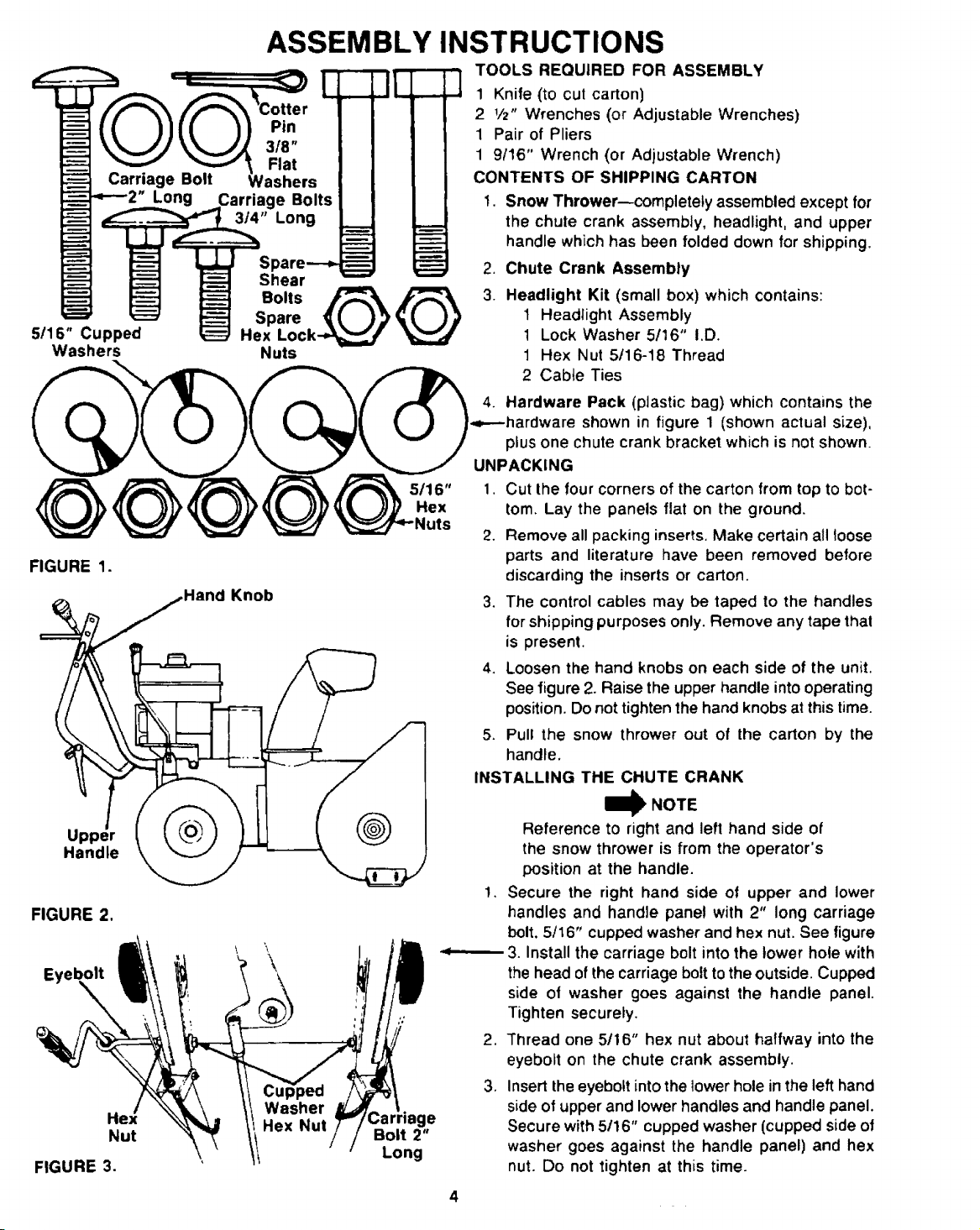
1 Knife (to cut carton)
2 1/2" Wrenches (or Adjustable Wrenches)
1 Pair of Pliers
1 9/16" Wrench (or Adjustable Wrench)
CONTENTS OF SHIPPING CARTON
1. Snow Thrower--completely assembled except for
the chute crank assembly, headlight, and upper
handle which has been folded down for shipping.
2. Chute Crank Assembly
3. Headlight Kit (small box) which contains:
1 Headlight Assembly
1 Lock Washer 5116" I,D.
1 Hex Nut 5/16-t8 Thread
2 Cab4e Ties
4. Hardware Pack (plastic bag) which contains the
-,---hardware shown in figure 1 (shown actual size),
plus one chute crank bracket which is not shown.
UNPACKING
1. Cut the four corners of the carton from top to bot-
tom. Lay the panels flat on the ground.
2. Remove all packing inserts, Make certain all loose
parts and literature have been removed before
discarding the inserts or carton.
3. The control cables may be taped to the handles
for shipping purposes only. Remove any tape thai
is present.
4. Loosen the hand knobs on each side of the unit.
See figure 2. Raise the upper handle into operating
position. Do not tighten the hand knobs at this time.
5. Pull the snow thrower out of the carton by the
handle.
INSTALLING THE CHUTE CRANK
I_ NOTE
Reference to right and left hand side of
the snow thrower is from the operator's
position at the handle.
!. Secure the right hand side of upper and lower
handles and handle panel with 2" long carriage
bolt. 5116" cupped washer and hex nut. See figure
3. Install the carriage bolt into the lower hole with
the head of the carriage bolt to the outside. Cupped
side of washer goes against the handle panel.
Tighten securely.
2. Thread one 5/16" hex nut about halfway into the
eyebolt on the chute crank assembly.
3. Insert the eyebolt into the lower hole in the left hand
side of upper and lower handles and handle panel.
Secure with 5/16" cupped washer (cupped side of
washer goes against the handle panel) and hex
nut. Do not tighten at this time.
4
Page 5
Chute
Crank
Bracket
Cupped
Hex,
Nuts
FIGURE 4.
Cotter
Pin
Washers
FIGURE 5.
Flat
Chute
Bracket
Crank /
Lever
Carriage,/4.LongB°ltsi
Rubberl,II II / //
I
!f
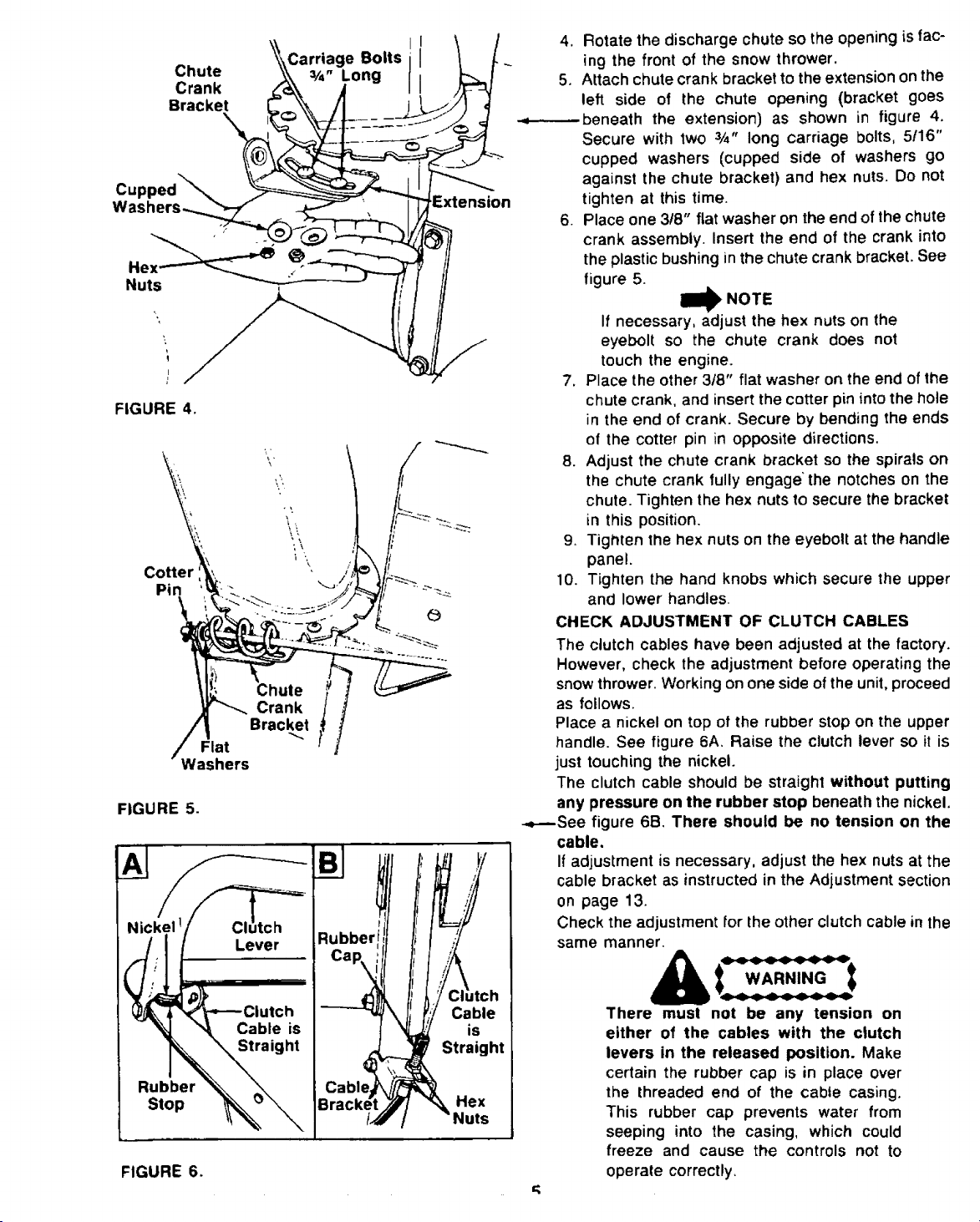
4. Rotate the discharge chute so the opening is fac-
ing the front of the snow thrower.
5, Attach chute crank bracket to the extension on the
left side of the chute opening (bracket goes
-,----.---beneath the extension) as shown in figure 4.
Secure with two 3/4" long carriage bolts, 5/16"
cupped washers (cupped side of washers go
against the chute bracket) and hex nuts. Do not
tighten at this time.
6. Place one 3t8" flat washer on the end of the chute
crank assembly, insert the end of the crank into
the plastic bushing in the chute crank bracket. See
figure 5.
I_ NOTE
If necessary, adjust the hex nuts on the
eyebolt so the chute crank does not
touch the engine.
7. Place the other 3/8" flat washer on the end of the
chute crank, and insert the cotter pin into the hole
in the end of crank. Secure by bending the ends
of the cotter pin in opposite directions.
8. Adjust the chute crank bracket so the spirals on
the chute crank fully engage"the notches on the
chute. Tighten the hex nuts to secure the bracket
in this position.
9. Tighten the hex nuts on the eyebolt at the handle
panel,
10. Tighten the hand knobs which secure the upper
and lower handles.
CHECK ADJUSTMENT OF CLUTCH CABLES
The clutch cables have been adjusted at the factory.
However, check the adjustment before operating the
snow thrower. Working on one side of the unit, proceed
as follows.
Place a nickel on top of the rubber stop on the upper
handle. See figure 6A, Raise the clutch lever so it is
just touching the nickel.
The clutch cable should be straight without putting
any pressure on the rubber stop beneath the nickel.
-.,----See figure 6B. There should be no tension on the
cable.
If adjustment is necessary, adjust the hex nuts at the
cable bracket as instructed in the Adjustment section
on page 13.
Check the adjustment for the other clutch cable in the
same manner.
Rubber
Stop
FIGURE 6.
Cable is
Straight
,_ is
Straight
Cable_ i/t_j_'_
Bracket _Y_ "_ Hex
t_/" / "Nuts
WARNING
There must not be any tension on
either of the cables with the clutch
levers in the released position. Make
certain the rubber cap is in place over
the threaded end of the cable casing.
This rubber cap prevents water from
seeping into the casing, which could
freeze and cause the controls not to
operate correctly.
Page 6
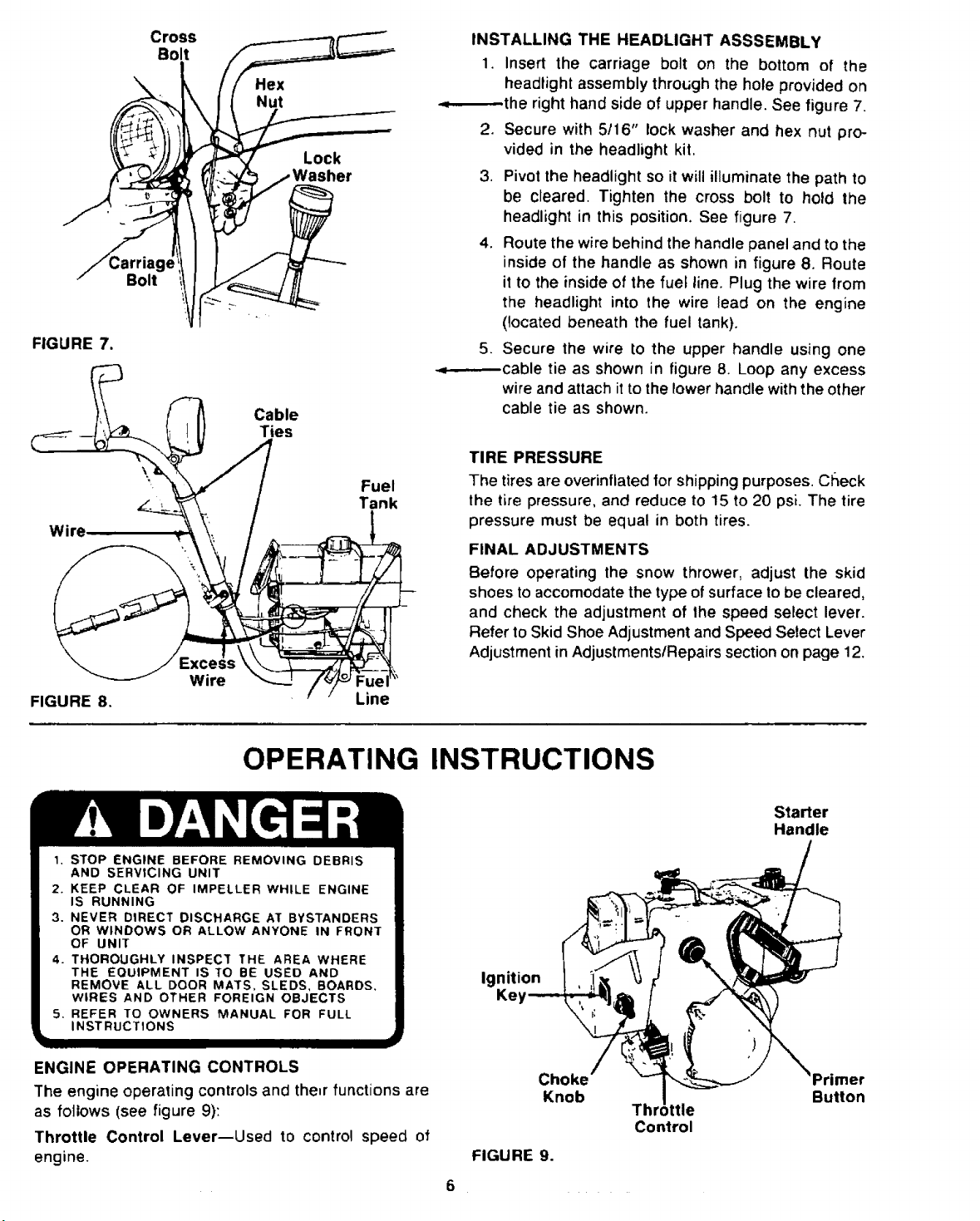
FIGURE7.
Wire
FIGURE8.
\
Bolt
Cross
Bolt
Wire
Hex
Nut
Cable
Ties
Lock
Fuel
Tank
Line
INSTALLING THE HEADLIGHT ASSSEMBLY
1. Insert the carriage bolt on the bottom of the
headlight assembly through the hole provided on
the right hand side of upper handle. See figure 7.
2. Secure with 5/16" lock washer and hex nut pro-
vided in the headlight kit,
3, Pivot the headlight so it will illuminate the path to
be cleared. Tighten the cross bolt to hold the
headlight in this position. See figure 7,
4. Route the wire behind the handle panel and to the
inside of the handle as shown in figure 8. Route
it to the inside of the fuel line. Plug the wire from
the headlight into the wire lead on the engine
(located beneath the fuel tank).
5. Secure the wire to the upper handle using one
-. cable tie as shown in figure 8. Loop any excess
wire and attach it to the lower handle with the other
cable tie as shown.
TIRE PRESSURE
The tires are overinflated for shippingpurposes. Cl_eck
the tire pressure, and reduce to 15 to 20 psi. The tire
pressure must be equal in both tires.
FINAL ADJUSTMENTS
Before operating the snow thrower, adjust the skid
shoes to accomodate the type of surface to be cleared,
and check the adjustment of the speed select lever.
Refer to Skid Shoe Adjustment and Speed Select Lever
Adjustment in Adjustments/Repairs sectionon page 12.
OPERATING INSTRUCTIONS
1. STOP ENGINE BEFORE REMOVING DEBRIS
AND SERVICING UNIT
2. KEEP CLEAR OF IMPELLER WHILE ENGINE
IS RUNNING
3. NEVER DIRECT DISCHARGE AT BYSTANDERS
OR WINDOWS OR ALLOW ANYONE IN FRONT
OF UNIT
4. THOROUGHLY INSPECT THE AREA WHERE
THE EQUIPMENT IS TO BE USED AND
REMOVE ALL DOOR MATS, SLEDS, BOARDS,
WIRES AND OTHER FOREIGN OBJECTS
5. REFER TO OWNERS MANUAL FOR FULL
INSTRUCTIONS
ENGINE OPERATING CONTROLS
The engine operating controls and the,r functions are
as follows (see figure 9):
Throttle Control Lever--Used to control speed of
engine.
Ignition
FIGURE 9.
6
Ke_
Choke
Knob
Thr, ,ttle
Control
Starter
Handle
Primer
Button
Page 7
ChokeKnob--UseFULLchokepositionto start a cold
engine.
Primer Button--Used toinject fuel directlyintothe car-
buretor to insure fast starts in cold weather.
Ignition Key--Must be inserted into ignition key slot
to startengine. Pull out tostop. Do not turn ignition key.
Starter Handle--Used tomanually start the engine. An
ElectricStarter kitisavailable. See Engine Repair Parts
section of this manual for kit number.
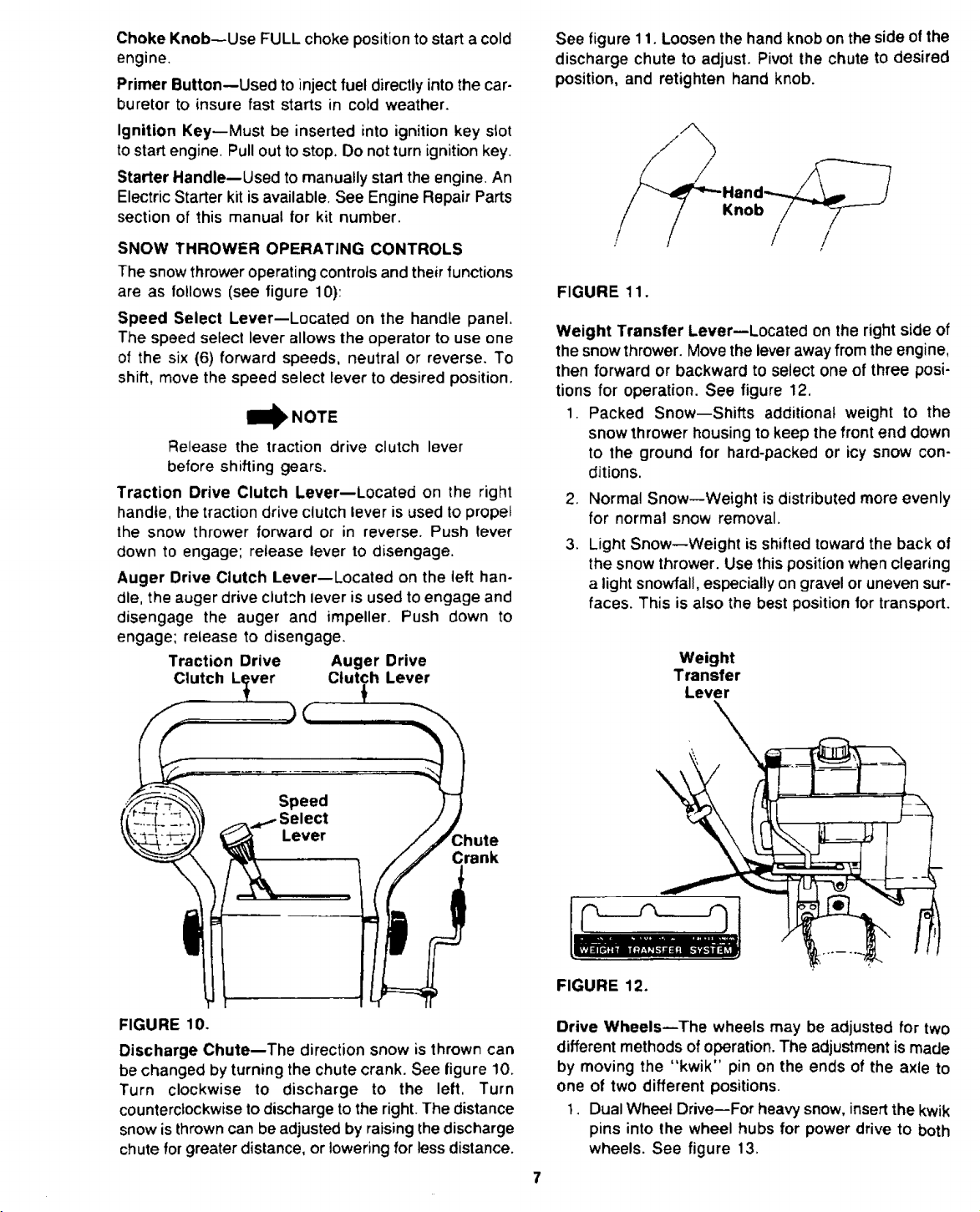
SNOW THROWER OPERATING CONTROLS
The snow thrower operating controtsandtheir functions
are as follows (see figure 10):
Speed Select Lever--Located on the handle panel.
The speed select lever allows the operator to use one
of the six (6) forward speeds, neutral or reverse. To
shift, move the speed select lever to desired position.
I_ NOTE
Release the traction drive clutch lever
before shifting gears.
Traction Drive Clutch Lever--Located on the right
handle, the traction drive clutch lever is used to propel
the snow thrower forward or in reverse. Push lever
down to engage; release lever to disengage.
Auger Drive Clutch Lever--Located on the left han-
dle, the auger drive clutch lever is used to engage and
disengage the auger and impeller. Push down to
engage; release to disengage.
Traction Drive Auger Drive
Clutch L_ver Clutch Lever
See figure 11. Loosen the hand knobon the side of the
discharge chute to adjust. Pivot the chute to desired
position, and retighten hand knob.
Knob
/ ,
FIGURE 11.
Weight Transfer Lever--Located on the right side of
the snow thrower. Move thelever away fromthe engine,
then forward or backward to select one of three posi-
tions for operation. See figure 12.
1. Packed Snow--Shifts additional weight to the
snow thrower housing to keep the front end down
to the ground for hard-packed or icy snow con-
ditions.
2. Normal Snow--Weight isdistributed more evenly
for normal snow removal.
.
Light Snow--Weight is shifted toward the back of
the snow thrower. Use this position when clearing
a light snowfall, especially on gravel or uneven sur-
faces. This is also the best position for transport.
Weight
Transfer
Lever
3hute
Crank
FIGURE 10.
Discharge Chute--The direction snow is thrown can
be changed by turning the chute crank. See figure 10.
Turn clockwise to discharge to the left, Turn
counterclockwise to discharge to the right. The distance
snow is thrown can be adjusted by raising the discharge
chute for greater distance, or lowering for less distance.
FIGURE 12.
Drive Wheels--The wheels may be adjusted for two
different methods ofoperation.The adjustmentismade
by moving the "kwik" pin on the ends of the axle to
one of two different positions.
t. DualWheel Drive--For heavy snow, insertthe kwik
pins into the wheel hubs for power drive to both
wheels. See figure 13.
Page 8
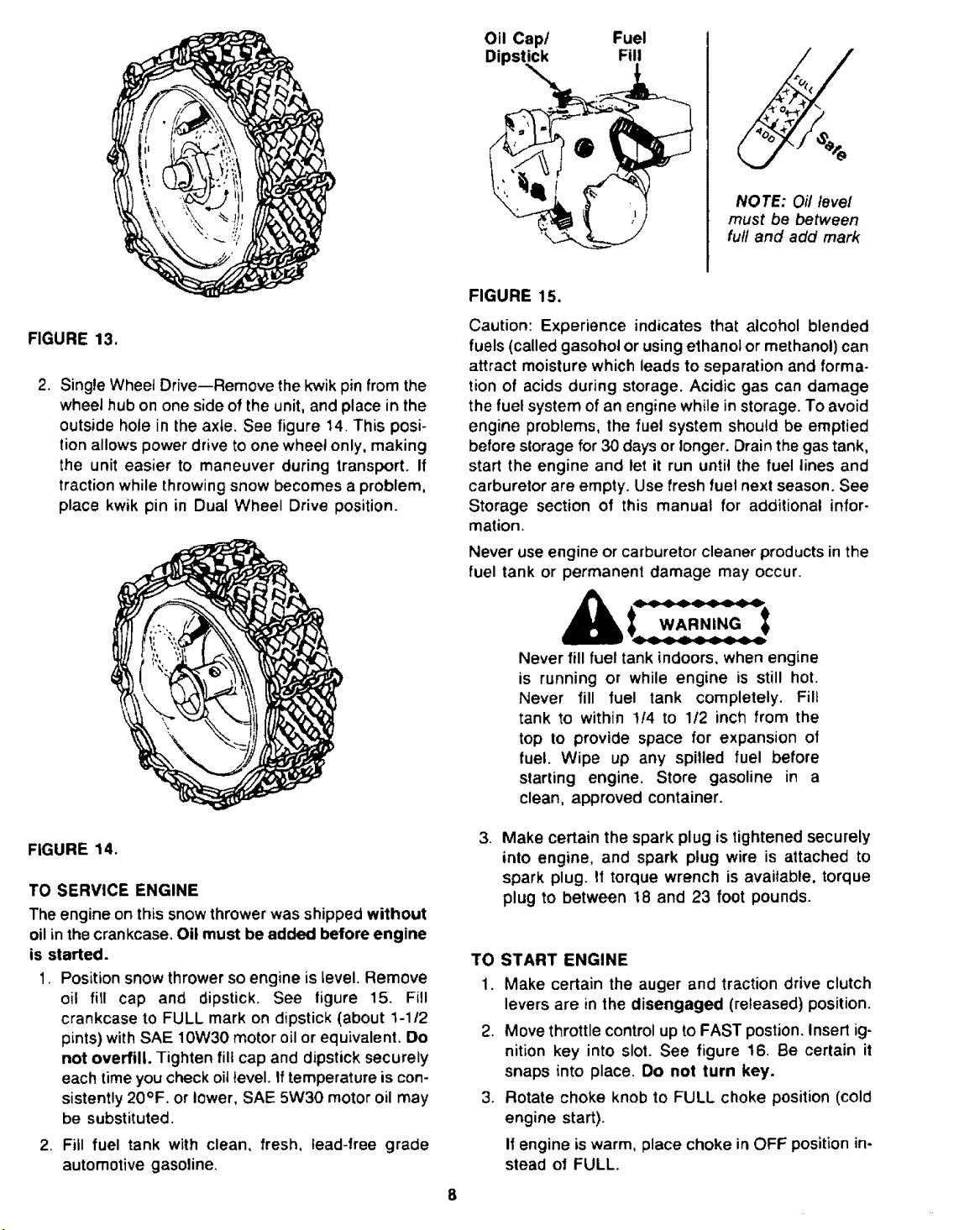
Oil Cap/ Fuel
Dipstick Fill
FIGURE 15.
NOTE: Oil level
must be between
full and add mark
FIGURE 13.
2. Single Wheel Drive--Remove the kwik pin from the
wheel hub on one side of the unit, and place in the
outside hole in the axle. See figure 14. This posi-
tion allows power drive to one wheel only, making
the unit easier to maneuver during transport. If
traction while throwing snow becomes a problem,
place kwik pin in Dual Wheel Drive position.
Caution: Experience indicates that alcohol blended
fuels (called gasohol or using ethanol or methanol) can
attract moisture which leads to separation and forma-
tion of acids during storage. Acidic gas can damage
the fuel system of an engine while in storage. To avoid
engine problems, the fuel system should be emptied
before slorage for 30 days or longer. Drain the gas tank,
start the engine and let it run until the fuel lines and
carburetor are empty. Use fresh fuel next season. See
Storage section of this manual for additional infor-
marion.
Never use engine or carburetor cleaner products in the
fuel tank or permanent damage may occur.
WARNING
Never fill fuel tank indoors, when engine
is running or while engine is still hot.
Never fill fuel tank completely. Fill
tank to within !!4 to 1/2 inch from the
top to provide space for expansion of
fuel. Wipe up any spilled fuel before
starting engine. Store gasoline in a
clean, approved container.
FIGURE 14.
TO SERVICE ENGINE
The engine on this snowthrower was shipped without
oil in the crankcase, Oil must be added before engine
is started.
1, Position snow thrower so engine is level. Remove
oil fill cap and dipstick. See figure 15. Fill
crankcase to FULL mark on dipstick (about 1-112
pints) with SAE 10W30 motor oil or equivalent. Do
not overfill. Tighten fill cap and dipstick securely
each time you check oit level. If temperature is con-
sistently 20°F. or lower, SAE 5W30 motor oil may
be substituted.
2. Fill fuel tank with clean, fresh, lead-free grade
automotive gasoline.
3. Make certain the spark plug is tightened securely
into engine, and spark plug wire is attached to
spark plug. If torque wrench is available, torque
plug to between !8 and 23 foot pounds.
TO START ENGINE
1. Make certain the auger and traction drive clutch
levers are in the disengaged (released) position.
2. Move throttle control up to FAST postion. Insert ig-
nition key into slot. See figure 16. Be certain it
snaps into place. Do not turn key.
3. Rotate choke knob to FULL choke position (cold
engine start).
If engine iswarm, place choke in OFF position in-
stead of FULL.
8
Page 9
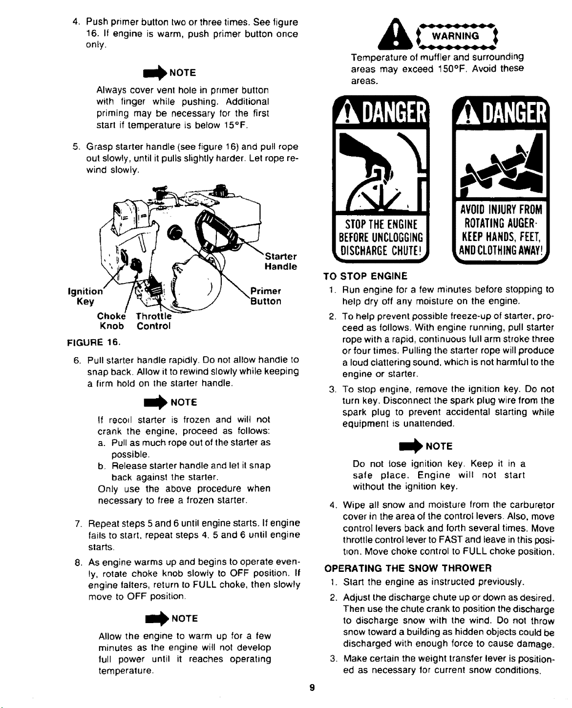
4, Push primer button twoor three times. See figure
16. If engine is warm, push primer button once
only.
Always cover vent hole in primer button
with finger while pushing. Additional
priming may be necessary for the first
start if temperature is below 15°F.
.
Grasp starter handle (see figure 16) and pull rope
out slowly, until it pulls slightly harder. Let rope re-
wind slowly,
'Starter
Handle
Ignition
Primer
Key
Throttle
Knob
Control
FIGURE 16.
6.
Pull starter handle rapidly. Do not allow handle to
snap back. Allow it to rewind slowly while keeping
a firm hold on the starter handle.
Iml_ NOTE
If recoil starter is frozen and will not
crank the engine, proceed as follows:
a. Pull as much rope out of the starter as
possible.
b. Release starter handle and let it snap
back against the starter.
Only use the above procedure when
necessary to free a frozen starter.
7=
Repeat steps 5 and 6 until engine starts. If engine
fails to start, repeat steps 4. 5 and 6 until engine
starts.
.
As engine warms up and begins to operate even-
ly, rotate choke knob slowly to OFF position, If
engine falters, return to FULL choke, then slowly
move to OFF position.
I_ NOTE
Allow the engine to warm up for a few
minutes as the engine will not develop
full power until it reaches operating
temperature.
WARNING4_4__e'_I
Temperature of muffler and surrounding
areas may exceed 150°F, Avoid these
areas.
AVOIDINJURYFROM
ROTATINGAUGER-
KEEPHANDS,FEET,
LANDCLOTHIN(;AWAY
TO STOP ENGINE
1. Run engine for a few minutes before stopping to
help dry off any moisture on the engine.
2. To help prevent possible freeze-up of starter, pro-
ceed as follows. With engine running, pull starter
rope with a rapid, continuous lull arm stroke three
or four times. Pulling the starter rope will produce
a loud clattering sound, which is not harmful to the
engine or starter.
3. To stop engine, remove the ignition key. Do not
turn key. Disconnect the spark plug wire from the
spark plug to prevent accidental starting while
equipment is unattended.
11_ NOTE
Do not lose ignition key. Keep it in a
sale place. Engine will riot start
without the ignition key.
4. Wipe all snow and moisture from the carburetor
cover in the area of the control levers. Also, move
control levers back and forth several times. Move
throttle control lever to FAST and leave in this posi-
t_on. Move choke control to FULL choke position.
OPERATING THE SNOW THROWER
1. Start the engine as instructed previously.
2. Adjust the discharge chute up or down as desired.
Then use the chute crank to positionthedischarge
to discharge snow with the wind. Do not throw
snow toward a buildingas hidden objectscould be
discharged with enough force to cause damage.
3, Make certain the weight transfer lever is position-
ed as necessary for current snow conditions,
IIIII
Page 10
4_
With the traction drive clutch lever released, use
the speed select lever to set desired speed, Use
a slower ground speed for wet, heavy or deep
snow. Reduce speed if the wheels slip. Operate
the engine at full throttle for maximum efficiency.
WARNING,I_ _
Be certain the traction drive clutch
lever is released before moving the speed
select lever.
.
Making certain no bystanders or obstacles are in
front of the unit, engage the auger drive clutch
lever (located on left handle).
.
Engage the traction drive clutch lever, located on
the right handle. As the snow thrower starts to
move, maintain a firm hold on the handle, and
guide the snow thrower along the path to be
cleared. Do not attempt the push the snow thrower.
MAINTENANCE
To stop the forward motion, release the traction drive
clutch lever. Release the auger drive clutch lever to stop
the snow throwing action.
Operating Tips
1. Formostefficient snow removal, remove snow im-
mediately after it falls.
2. Discharge snow downwind whenever possible.
Slightly overlap each previous swath,
3. Set the skid shoes 1/4" below the scraper bar for
normal usage, The skid shoes may be adjusted up-
ward for hard-packed snow. Adjustdownward (rais-
ing the scraper bar) when using on gravel or
uneven surfaces.
4. Be certain to follow the precautions listed under
"To Stop Engine" on page 9 to prevent possible
freeze-up.
5. Clean the snow thrower thoroughly after each use.
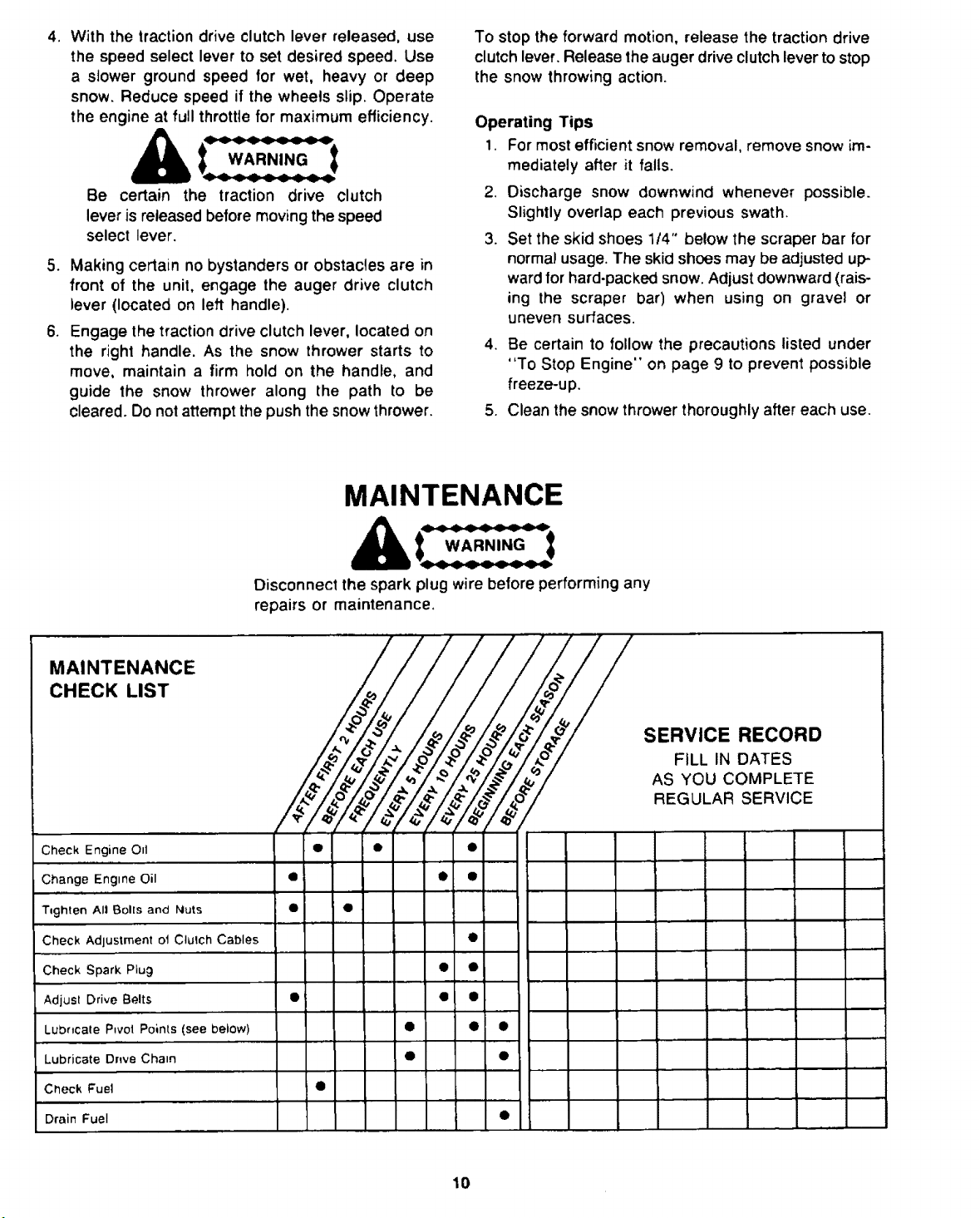
WARNING
Disconnect the spark plug wire before performing any
repairs or maintenance,
CHECK LIST _ I
._ v ,v -- '_ _ "_ FILL IN DATES
_ _ "_ _ _ _ AS YOU COMPLETE
! REGULAR SERVICE
Check Engine O_t • • •
Change Engine Oil O i • t
T_ghten All Bolls and Nuts • •
Check Adjustment o1 Clutch Cables •
Check Spark Piug • •
Adjust Drive Belts • • •
Lubricate Pivot Points (see below) • • •
Lubricate Drwe Chain • @
, ,,,,,,,,, ,.......
,.d
,,,,,,,,,,,,,,,,,,,
SERVICE RECORD
Check Fuel •
Drain Fuel I •
10
Page 11

The Maintenance Check List is supplied to assist the
operator in proper maintenance of the snow thrower.
This is only a check list; instructions for adjustments
will be found in the Adjustments/Repairs section of this
manual.
Some adjustments will need to be made periodically
to properly maintain your snow thrower.
Drive Chain--Using engine oil, lubricate the drive
chain after each 10 hours of operation and before
storage as follows.
1. Make certain the speed select lever is in Neutral.
Tip the snow thrower forward so it rests on the
housing.
All adjustments in AdjustmentstRepairs section of this
manual should be checked at least once a season, The
following should be performed more than once each
season.
All Bolls and Nuts--Should be checked often to make
certain they are tight, preferably after each use.
Engine and Snow Thrower--Lubricate as instructed
in the following section.
LUBRICATION
Engine Lubrication--Check Oil Level before starting
engine and every 5 hours of operation. Oil level must
be maintained between the "Full" and "Add" marks
on dipstick. Refer to "'To Service Engine" instructions
on page 8.
Change Oil after first 2 hours of operation and every
25 hours thereafter, Change at least once a year if the
snow thrower is not used for 25 hours.
, There are two openings in the bottom cover. The
drive chain can be oiled through the left opening.
Turn the left wheel by hand to rotate the chain so
the entire chain can be lubricated.
Pivot Points--Grease pivot slots and pivot arms (both
sides of unit) before each season, before storage and
after each 10 hours of operation, using a mufti-purpose
automotive grease. See figure 18. After applying
grease, work the weight transfer lever back and forth
to distribute the grease.
I_1) NOTE
Figure 18 isshown withthe wheel removed
for clarity only. It is not necessary to
remove the wheel to lubricate the pivot
slots and pivot arms.
Pivot
To drain oil, position snow thrower so the oil drain plug
is the lowest point on the engine. Remove oil drain plug
and oil fill cap. See figure 17. Drain oil into a suitable
container. Oil will drain more freely when warm.
Replace oil drain plug and tighten securely. Refill
crankcase with SAE 10W30 motor oil, SAE 5W30 motor
oil may be substituted when temperature is consistently
20°F, or lower.
Oil
Dipstick
j,,
NOTE: Oil level
Plug
FIGURE 17.
must be between
full and add mark
Slot
FIGURE 18.
Transmission--The transmission is lubricated at the
factory and does require not additional lubrication. If
the transmission is disassembled for service, lubricate
with 12 ounces of Benalene grease. Order part number
737-0223 (10 ounce tube)through yournearest Sears
Service Center.
11
Page 12

STORAGE
: w...,.o:
• +
Never store engine with fuel in tank
indoors or in poorly ventilated
enctosures, where fumes may reach an
open flame, spark or pilot light such
as on a furnace, water heater, clothes
dryer, etc.
It is important to prevent gun deposits from forming Jn
essential fuel system parts such as the carburetor, fuel
hose or fuel tank during storage. Aiso, experience in-
dicates that atcohol blended fuels (called gasoho! or
using ethanol or methanol) can attract moisture which
leads to separation and formation of acids during
storage. Acidic gas can damage the fuel system of an
engine while in storage.
To avoid engine problems, the fuel system should be
emptied before storage of 30 days or longer. Follow
these instructions.
!. Run engine until fuel tank is empty and engine
stops due to lack of fuel.
2. Disconnect fuel hne at carburetor or fuel tank. Be
careful not to damage tuel line, fittings or fuel tank.
Drain any remaining fuel from the system.
WARNINGS:
Drain fue! into approved container
outdoors, away from open flame.
If gasohol has been used, complete the
preceding instructions. Then put a small
amount of unleaded (or regular) grade
gasoline into fuel tank and repeat steps
1 and 2.
,
Change oil if it has not been changed recently.
Refer to Maintenance section.
4,
Remove the spark plug and squirt one ounce of
clean engine oil into spark plug hole. Cover the
spark plug hole with a clean rag. Purl the starter
rope slowly to allow the piston to coat the internal
engine parts. Reinstall the spark plug. Do not con-
nect spark plug wire.
5. Thoroughly clean the snow thrower, if unit is to be
stored in an unventilated or metal storage shed,
coat any metal parts with a light oil or silicone to
prevent rust.
6. Store in a clean, dry area.
ADJUSTMENTS/REPAIRS
_ WARNING_
Always stop engine and disconnect spark
plug wire before performing any
adjustments or repairs.
SKID SHOE ADJUSTMENT
The snow thrower is equipped with two adjustable skid
shoes, located on each side ofthe auger housing. The
skidshoes determine the distance between the scraper
bar and the ground, which varies according to the type
of surface to be cleared.
Normal, Hard Surfaces
When removingsnow from a normal, hard surface such
as a paved driveway or walk, the skid shoes should be
adjusted to be approximately 114" lower than the
scraper bar.
To adjust, proceed as foltows.
1. Place the weight transfer lever in the "Normal
Snow" (m+ddle)position.
2. Make certain both tires are inflated equally (15 to
20 psi),and that neither tire is resting on a link of
the tire chains.
3. Place the threaded ends of the spare shear bolts
(provided in hardware pack) under the scraper bar,
one at each end, See figure 19.
4. Loosen the four hex nuts on the skid shoes. Push
each skid shoe up or down until it touches the
ground. Retighten the hex nuts securely.
Make certain the snow thrower is set at the same height
on both sides, and the entire bottom surface of skid
shoe is against the ground to avoid uneven wear.
Uneven or Rocky Surfaces
When removing snow from uneven, rocky or gravel sur-
faces, raise the scraper bar by moving the skid shoes
down to avoid throwing gravel. Adjust as instructed
above, using thicker objects under the scraper bar to
act as spacers.
I_ NOTE
Both the skid shoes and the shave
plate are subject to wear and should
be replaced when necessary.
Page 13

_ _ Auger 7_
...... --Shear-
Bolts
/.: _/_
Shear Bolts _j_€ _
(Normal, Hard
FIGURE 19.
SPEED SELECT LEVER ADJUSTMENT
TO check the neutral adjustment for the speed select
lever, proceed as follows.
Place the speed select lever Jn the Neutral position.
With the traction drive clutch lever (right hand clutch
grip) engaged, rol! lhe unit back and forth, It should
move freely.
Move the shift lever to Reverse position. Engage the
fraction drive clutch lever, and roll the unit back and
forth. The wheels should lock up.
If adjustment is needed, loosen the hex nuts near the
top and bottom of the speed select rod (bottom nut has
left hand threads). See figure 20. Place the unit in
neufrat (unit will roll freety with the traction drive clutch
lever engaged). Check to see that the speed select
lever lines up with the "N" on the handle panel. If the
indicator on the lever is to the left of the "'N", turn the
rod clockwise to lengthen the rod as shown in figure
20. If the indicator on the lever is to the right of the "N",
turn the rod counterclockwise to shorten the rod.
Retighten the hex nuts when the correct adjustment is
reached.
Loo
Hex
Surfaces) Shoe
is necessary if there is excess slack in either cable with
the clutch lever released.
To adjust, loosen the hex nuts at the cable bracket. See
figure 21A. Place a nickel on top of the rubber stop on
the upper handte. Raise the clutch lever so it is just
touchingthe nickel. See figure 21B. Adjust the hex nuts
at the cable bracket so the clutch cable is straight
without putting any pressure on the rubber stop on
the handle. Move the hex nuts up toward the end of
the cable casing to tighten the cable; move the hex nuts
down to loosen the cable. When correct adjustment is
reached, retighten the hex nuts at the cable bracket.
Make certain to slide the rubber cap over the threaded
end of the cable casing.
I_ NOTE
There must not be any tension on
either cable with the clutch levers
in the released position.
Rubber ';l
Clutch
Lever
Bracket
Clutch
Cable
Straight
Hex
--Nuts
is
Rubber,s.
Stop
FIGURE 21.
BELT REPLACEMENT
Auger Drive Belt
1.
Disconnect the spark plug wire from the spa_k
plug.
,
Disconnect chute crank assembly at the discharge
chute by removing the cotter pin and flat washer.
,
Remove the plastic belt cover on the front of the
engine by removing three self-tapping screws. See
figure 22. A 112" wrench is required.
L°°sen H_hrNeU__
(Left Hand
FIGURE 20.
CABLE ADJUSTMENT
Periodic adjustment of the cables may be required due
to normal stretch and wear on the belts. Adjustment
Belt
Cover
Self-Tapping
FIGURE 22.
13
Page 14

4. Remove the hairpin clip shown in figure 23.
Unhook the brake spring from the weld pin on the
idler bracket.
Auger
j Belt
t]l_ NOTE
Figure 23 is show with the chute
assembly removed for clarity only.
It is not necessary to remove the
chute when replacing the belts.
5. Using a 1!2" wrench, loosen upper left hand belt
guard and pivot out of the way. Remove the right
hand belt guard and cupped washer, A 9116"
wrench is requJred.
6. Roll belt off the engine pultey.
7. Unhook the cable from the weld pin on the idler
bracket. See figure 23.
Right Upper Left
Belt Guard Belt Guard
pring
Weld Pin on
Idler Bracket
FIGURE 23.
Remove
Weig
Transfer
Lever
(Do Not
FIGURE 24.
I NOTE
Be certain to check the condition of
the drive belt when the two halves of
the unit are separated. Replace if
necessary.
.
Using a 15116" wrench, remove the four shoulder
bolts and cupped washers which act as belt
keepers. See figure 25.
10.
Roll belt off the auger pulley.
11.
Remove the second hairpin clip from the weld pin
on the idler bracket.
!2. Push the idler to the right to extend the spring.
Remove belt from between idler pulley and weld
pin. See figure 25.
13. Reassemble new belt in reverse order.
Idler
8. Separate the snow thrower
into two halves as
follows.
a. Move weight transfer lever to the "Packed
Snow" position.
b. Using a 9/16" wrench, remove the top bolts
which attach the auger housing to the frame
assembly. Loosen (do not remove) the bottom
bolts. See figure 24.
c. Lift up on the auger drive belt to pull the auger
housing off the frame assembly, The snow
thrower will separate into two halves.
d. Tip the auger housing forward so it rests on the
front of the housing.
Auger_ 'X_k.-_,-=J_/'//]_ /
Pulley _l "_.'\_/ !_/
Belt Keepers
FIGURE 25.
14
Page 15

Drive Belt
1. Follow steps 1 through 8 of the previous section.
Allen
Wrench
2. Disconnect the drive cable from the traction drive
clutch lever (on right side of handle) by removing
the hex nut and slipping the cable off the weld pin.
3. Unhook the spring from the idler bracket. See
figure 26.
Unhook
!pring
FIGURE 26.
4.
Slip belt from between belt guard and fixed idler
pulley as shown in figure 27.
5r
Using a 1/8" Allen wrench, loosen (do not remove)
the two set screws in the groove of the fixed idler
pulley.
NOTE
The lwo set screws are on opposite
sides of the pulley. It may be
necessary to pull the starter rope
slightly to rotate the pulley, which
wil! allow access to the set screws.
Be certain spark plug wire is discon-
nected.
.
Remove the fixed idler putley and belt. Remove
belt from around idler pulley.
Idler
Fixed
Idler
Center
Nut
FIGURE 27.
AUGER SHEAR BOLT REPLACEMENT
The augers are secured to the auger shaft with two
specialshear bolts and hexlock nuts.if youhita foreign
object or icejam, snow thrower isdesigned sothe bolts
will break (to protect the snow thrower). Refer tofigure
19,
If the augers will not turn, check to see if the hex bolts
have sheared. Two spare bolts and hex lock nuts have
been provided with the snow thrower. Use only original
equipment shear bolts and nuts, part numbers
710-0890 (shear bolt)and 712-0429 (hex lock nut).
SPARK PLUG
Clean spark plug and reset gap periodically. Clean area
around spark plug base before removing to prevent dirt
from entering engine. Replace spark plug ifelectrodes
are pitted or burned, or if porcelain is cracked. Spark
plugreplacement is recommended at beginning ofeach
season. Reter to Engine Repair Parts section of this
manual for proper replacement plug. If reusing spark
plug, clean by carefully scraping electrodes (do not
sand blast or use wire brush). Be certain entire spark
plug is clean. Cleck electrodes gap with a wire feeler
gauge, and reset gap to 0.030 if necessary. See figure
28.
Install spark plug in engine, and tighten securely. If tor-
que wrench is available, torque plug to between t8 and
23 foot pounds.
.030
7.
Using a 3/4" socket wrench, remove the center nut
from the drive pulley. Slide pulley out, and remove
the belt.
8.
Reassemble the new belt, following instructions in
reverse order.
FIGURE 28.
15
Page 16

CARBURETOR ADJUSTMENT
WA RNiNG4_'4_'e'_' t
Allow the engine to run undisturbed for a few seconds
between each new setting so that the engine can react
to each setting.
If any adjustments are made to the
engine while the engine is running
(e.g., carburetor), keep clear of all
moving parts. Be carefuZ of heated
surfaces and muffler.
The carburetor has been pre-set at the factory and
should not require adjustment. However, if the car-
buretor needs adjustment, proceed as follows. See
figure 29.
1. Close high speed adjusting screw by hand. Do not
overtighten. Then open it 1 114 to 1 !t2 turns.
2. Close idle adlusting screw by hand. Do not over-
tighten. Then open it 1 1/4 to 1 1/2 turns.
3. Start the engine, and allow it to warm up.
4, Set the throttle control to FAST. Adjust high speed
adjusting screw in or out until the engine runs
smoothly at full throttle. If the engine has a tenden-
cy to stall under load, open high speed adjusting
screw slightly to obtain a richer fuel mixture.
5. Set the throttle control to SLOW. Adjust idle a0-
justing screw in or out until the engine runs
smoothly at idle.
WARNING
Never tamper with the engine governor,
which is set at the factory for proper
engine speed. Overspeeding the engine
above factory high speed setting is
dangerous. If you think the engine
governed high speed needs adjusting,
contact your nearest SEARS Service
Center, who has the proper equipment
and experience to make any necessary
adjustments.
_,,...--. High*Speed Adjustment Needle
(Close Finger Tight Only)
FIGURE 29.
16
Page 17

TROUBLE SHOOTING GUIDE
TROUBLE POSSIBLE CAUSE(S) CORRECTIVE ACTION
Engine fails to start
Engine runs erratic
Loss of Dower
Engine overheats
Excessive wbration
Hard to shift, or will
not shift
1, Fuel tank empty, or stale fuel.
2. B_ocked fuel line.
3. Key not in switch on eng,ne.
4+ Spark plug wire disconnecled.
5. Faulty spark plug.
1. Unit running on CHOKE.
2. Blocked fuel line or stale fuel.
3. Water or dirt in fuel system.
4. Carburetor out of adjustment.
1. Spark plug wire loose.
2. Gas cap vent hole plugged.
1. Carburetor not adjusted
properly.
2+
Engine oil level low.
Loose parts or damaged
impeller.
Speed select rod misadjusted
1 Fill tank with clean, fresh gasoline.
2. Clean fuel line.
3, Insert key+
4. Connect wire to spark plug.
5. Clean, adjust gap or replace.
1, Turn choke knob to OFF position.
2, Clean fuel line; fill tank with clean
fresh gasoline.
3, Remove carburetor bowl to drain fuel tank.
Refill with fresh fuel.
4, Adjust carburetor (see Carburetor Adjustment in
Adjustments/Repairs section of this manual).
........ , ., ,,,,,,,,,
1. Connect and tighten spark plug wire.
2. Remove ice and snow from cap.
Be certain vent hote is clear,
1+ Adiust carburetor (see Carburetor
Adjustment in Adjustments/Repairs section
of this manual).
2. Fill crankcase with the proper oil+
Stop engine immediately and disconnect
spark plug wire, Tighten all bolls and nuts.
Make all necessary repairs. Ifvibration continues,
have unit serviced by a SEARS Service Center.
Readjusl speed select rod (see Speed Select
Lever Adjustment in Adjustments/Repairs
section of this manual).
Unit fails to propel
itself
1. Unit in neutral.
t. Move speed select lever to one of the 6
forward speeds or reverse (readjusl speed
select lever if needed),
2. Kwik pins not in proper position.
3. Incorrect adjustment el traction
drive cable.
2. Place kwik pins in wheel hub.
3. Adjust traction drive cable. Refer to Cable
Adjustment in Adjustments/Repairs section
of this manual.
4. Drive bell loose or damaged.
4. Replace drive belt. Refer to Belt
Replacement in Adjustments/Repairs
section of this manual.
5. Transmission problem.
5, Have unit serviced by a SEARS Service
Center.
Unit fails to
discharge snow
1. Shear bolt broken.
1. Replace shear bolt. Refer to Auger Shear
Bolt Replacement in Adjustments/Repairs
section of this manual.
2. Discharge chute clogged.
2. Stop engine immediately and disconnect
spark piug wire. Clean discharge chute
and inside of auger housing.
3. Foreign object lodged in auger.
3. Stop engine immediately and disconnect
spark plug wire. Remove object from auger.
4. Incorrect adjustment of auger
drive cable,
4. Adjust auger drive cable. Refer to Cable
Adjustment in Adjustments/Repairs section
of this manual.
5. Auger drive belt loose or
damaged.
5. Replace auger drive belt. Refer to Belt
Replacement in AdjustmentslRepairs
section el this manual.
NOTE: For repairs beyond the minor adjustments listed above, please contact your nearest SEARS Service Center.
17
Page 18

SEARS CRAFTSMAN 26" SNOW THROWER MODEL NO. 247.886700
Repair Parts--Handle Details
"23
14
47 39
/
_42
24
6
4132 5_?
9 13
.
36 45
18
49
Page 19

SEARS CRAFTSMAN 26" SNOW THROWER MODEL NO. 247.886700
Repair Parts
KEY
NO.
1
2
3
7
8
9
10
11
12
13
14
15
!6
17
18
19
20
21
22
23
24
25
26
31
32
i33
PART
NO.
09966
710-0136
7t0-0216
710-0572
712-0291
712-0798
712-0392
712-0267
731-0496
735-0199
736-0169
736-0242
738-0560
738-0561
746-0692
746-0693
749-0779
749-0780
749-0783
784-5394
784-5395
784-5431
784-5432
784-5433
736-0142
712-0181
712-0241
712-0312
DESCRIPTION
Hand Knob
Hex Bolt 1/4-20x 1,75" Lg.
Hex Bolt 318-16 x .75" Lg.*
Carriage Bolt 5116-18 x 2,5" Lg,
Hex L-Nut 1/4-20Thd
Hex Nut 318-16 Thd,"
Hex Lock Stop Nut 1/4-28Thd.
Hex Nut 5/16-18 Thd."
Plastic Plug
Rubber Bumper
L-Wash. 318" I.D.*
Bell-Wash..345" I.D,
Shld, 8olt ,374" Dia,
Shld, Nut 1/4-20 Thd.
Clutch Cable 25.5" Lg.
Auger Cable 25.5" Lg.
Lower Handle--R,H.
Lower Handte--L.H,
Upper Handle Ass'y.
Cable Bracket--R,H.
Cable Bracket--L.H,
Clutch Grip Ass'y,--L,H.
Clutch Grip Ass'y,--R,H
Handle Panel Ass'y.
R-Wash. 114" I,D, x 1t2" O.D.
Hex Ins. L-Nut 3/8-t6 Thd.
Hex Nut 3/8-24 Thd.
Hex Nut 3t8-24 L.H. Thd.
KEY
NO.
341
351
39
40
41
42
43
45
46
47
48
49
5O
51
52
53
54
55
56
57
58
59
60
6!
62
PART
NO,
712-0711
723-0156
723-0351
736-0169
736-0185
736-0256
736-0219
738-0372
747-0577
784-5390
784-5392
720-0218
710-0487
784-5388
710-0599
O598O
715-0138
720-0201A
726-0100
741-0475
747-0416A
784-5386
736-0119
710-0116
13359
725- t 300
725-0586
770-6675D
DESCRIPTION
Hex Jam Nut 3/8-24 Thd,
Ball Joint Ass'y, 318-24 Thd.
Bali Joint Ass'y. 3!8-24 LH. Thd.
L-Wash, 3/8" I.D.*
FI-Wash..406" I.D.
FI-Wash..635" I.D.
Bell-Wash..39" I,D.
Shoulder Spacer
Shift Rod
Shift Arm
Shift Lever Ass'y.
Shift Knob
Carriage Bolt 5/16-18 x 2" Lg.
Bottom Cover
Hex TT-Tap Scr, 1/4-20 x .5" Lg.
Chute Crank Ass'y.
Roll Pin 1/8" Dia,
Chute Crank Knob
Pushnut 318" Rod
Plastic Bushing .38" I.D.
Eyebolt
Shift Support
L.Wash, 5t16" I.D,
Hex Bolt 5/16-18 x 2.0" Lg."
Lamp Mounting Brkt,
Headlight
Headlight Housing
Owner's Manual
"Common Hardware--May be purchased locally,
19
Page 20

SEARS CRAFTSMAN 26" SNOW THROWER MODEL NO. 247.886700
Repair Parts--Auger/Housing Details
36
35
9n
Page 21

SEARS CRAFTSMAN 26" SNOW THROWER MODEL NO. 247.886700
Repair Parts
"KEY { PART
NO, NO.
731-0848
710-0276
3 710-0166
4 731-0844
5 714-0507
6 710-0451
7 741-0475
8 738-0140
9 05980
10 74!-0155
11 750-0118
12 784-5123
13 756-0418
!4 714-0388
15 738-0154A
16 736-0105
17 736-0242
18 710-0255
19 784-5398
20 710-0790
21 05002
22 736-0105
23 7t2-0342
24 784-5244
25 715-0114
26 05865A
27 714-0133
28 741-0493
29 7t2-0429
30 738-0711A
31 736-0188
32 741-0300
33 O5845
34 710-0726
35 710-0890
36 05923
05924
37 721-0176
38 717-0456
39 74t-0293
4O 717-0457B
DESCRIPTION
Upper Chute
Carriage Bolt 5!16-18 x 1.0""
Truss Mach. Scr. t/4-20 x 1" *
Lower Chute
Cotter Pin
Carriage Bolt 5!16-18 x .75""
Bushing
FI-Wash..385 I.D. x .62" O.D.
Chute Crank Ass'y.
Ball Brg. ,62" I.D. x 1.38"
Spacer ,63" I.D. x .88" O.D.
Chute Crank Brkt.
518.... V"-Pulley .625" I.D. x
7.5" O,D.
#61 Hi-Pro Key 3tt6" x 518" Dia,
Shtd. Bolt .50" Dia. x 2.11"
Bell-Wash..40" I.D. x .88"
Bel!-Wash..34" ID. x .88"
Truss Mach. Scr. V4-20 x .75""
26" Blower Housing Ass'y.
Carriage Bolt 3/8-16 x ,62""
Slide Shoe
Bell-Wash. 3t8" I.D.
Hex Jam Nut 318-16 Thd.
26" Shave Plate
Spring Pin Spiral 1/=. Dia.
x 1.50" Lg.
11" Dia, Blower Fan Ass'y.
Sq. Key 3116" x 1.5" Lg.
Flange Brg. ,75" !.D. x 88"
Hex Ins. L-Nut 5116-18
Spiral Axle
Ft-Wash..75" I.D. x 1.50"
Flange Brg. w/Flats .755" I.D.
Bearing Housing
Hex Wash. Hd. Self-Tap Scr.
5116-24 x .62" Lg.
Shear Bolt 5/t6-18 x 1.5" Lg.
26" Spiral Ass'y.--L.H.
26" Spiral Ass'y.--R.H.
(Not Shown)
"O"-Ring--314" I.D.
Bevel Gear Housing--Lower Half
Plastic Flange Brg..755" I.D.
I
Bevel Gear
KEY
PART
NO.
41
NO,
712-0237
736-0264
748-0237
736-0287
748-0171
748-0106
738-0649
717-0455
710-0588
712-0267
710-0260
710-0427
736-0169
O5895
7!0-0723
09966
714-0104
736-0t42
61 712-0t07
62 731-085t
63 736-0116
64 712-0923
65 736-0231
66 712-0158
67 710-0323
68 750-0190
69 717-0836A
70 732-0550
71 732-0599
72 736-0219
73 738-0281
74 738-0347
76 754-0357
77 756-0225
78 784-5048
79 784-5426
80 710-0459
81 736-0169
82 736-0247
83 756-0533
84 714-0114
85 712-0266
86 784-0273
DESCRIPTION
Hex Cent. L-Nut 5/16-24 Thd.
Fl-Wash..34" I.D. x .62"
Pinion Gear
FI-Wash..75" I.D. x 1.25"
Flange Brg..755" I.D,
Sleeve Brg..755" I.D.
Blower Axle
Bevel Gear Housing--Upper Half
Hex Wash. Hd, Self-Tap
Scr. 1/4-20 x 100" Lg.
Hex Nut 5f16-1B Thd.*
Carriage Bolt 5!16-18 x .62" Lg,*
Hex Bolt 3/8-16 x 2" Lg."
L-Wash. 3/8" I.D."
Auger Clutch Idler Brkt.
Hex Bolt 3t8-16 x 125" Lg."
Knob
Int, Cotter Pin 5t16" Dia.
FI-Wash. 1/4" I.D
Hex L-Nut 1/4-20 Thd. °
Chute Flange Keeper
FI-Wash. °64" I.D. x .94"
Hex Jam Nut 518-18 Thd,
Ff-Wash..344 I,D. x 1.125
Hex L-Nut 5116-18 Thd.
Truss Mach. Scr. 5tt6-18 x ,75"
Lg.'
Spacer
Gear Box Complete
Extension Spring 4" Lg.
Extension Spring 3.3" Lg.
Bell-Wash, .4" I.D x 1.13"
Shld. Bolt .625" Dia.
Shld, Spacer .625" I.D.
V-Belt
Fl-tdler 3,12" O.D.
8rake Brkt. Ass'y,
Brake Link Ass'y.
Hex Bolt 318-24 x 1,5" Lg.
L-Wash, 3t8" I.D.*
Washer .39" I.D. x t.25"
Sq. Key I/4" x Lg.
Hex Jam Nut 3/8-16 Thd.
i ngine Pulley 2"
Chute Stop
"Common Hardware--May be purchased locally,
')t
Page 22

SEARS CRAFTSMAN 26" SNOW THROWER MODEL NO. 247.886700
Repair Parts--Drive Mechanism Details
/.,3
\
\
93
6
.\
62
59 55
22
/2
Page 23

SEARS CRAFTSMAN 26" SNOW THROWER MODEL NO. 247.886700
Repair Parts
KEY
NO.
10
11
12
13
15
!6
17
18
20
21
22
23
24
25
26
27
28
29
30
31
32
33
34
35
36
37
38
39
40
41
42
43
44
45
46
PART
NO, DESCRIPTION
1
784-5384
2
784-5386
3
784-5382
4
736-0329
5
712-0287
6
710-0599
7
710-0623
Frame Ass'y.
Shift Support
Back Plate Ass'y.
L-Wash. I/4" I.D."
Hex Nut 1/4-20 Thd."
Hex TT-Tap Scr. I/4-20 x .5" Lg.
Hex Self-Tap Scr. 318-16 x .75"
Lg.
8
736-0217
714-0143
734-1417
734-1375
734-0255
734-1145
741-0401
736-0287
736-0315
750-0442
710-0118
7!0-0442
710-0603""
L-Wash. 3!8" I.D.
Kwick Pin
Wheet Ass'y. Comp.
Tire Only
Air Valve
Rim Only
Sleeve Brg..755" I.D.
FI-Wash. ,793" I.D.
FI-Wash..75" I.D.
Spacer .75" I.D.
Hex Bolt 5116-18 x .75" Lg."
Hex Bolt 5116-18 x 1.5" Lg."
Hex Wash. Hd. B-Tap Scr.
5/16-18 x .5" Lg,"
710-0459
710-0874
711-0640
712-0241
712-0267
712-0333
712-0342
717-0944
732-0429
736-0119
73_0t69
736-0921
738-0689
750-0539
754-0356
756-0536
756-0537
784-5314
784-5315
714-0129
143.796132
710-0559
736-0270
784-5390
Hex Bolt 3/8-24 x 1.5" Lg.
Hex Bolt 5116-18 x 1.25" Lg."
Stud 3/8-16 x 2.75" Lg.
Hex Nut 3/8-24 Thd.
Hex Nut 5!16-18 Thd.*
Nut 1/2-20Thd.
Hex Jam Nut 3/8-16 Thd.
Transmission Comp.
Extension Spring 3.97" Lg.
L-Wash. 5/16" I.D.*
L-Wash. 318" I.D."
L-Wash. 1/2" I.D.*
Shld. Bolt 1/2" Dia. x ,175"
Spacer .315" f.D.
V-Belt
Flat Idler 1.88" Dia.
Trans. Pulley 7" O.D. x 3L
Trans. Idler Arm
Trans. Support Plate
Key
Engine
Hex Bott 1/4-28x 1.75" Lg.
Bell-Wash. 114" I.D.
Shift Arm
KEYi
NO,W
47J
481
491
501
5!!
531
541
551
561
57!
581
591
601
61_
621
63 i
64
65
7O
71
73
74
75
76
78
80
81
82
86
88
89
90
9t
92
93
94
95
96
97
98
99
100
PART
NO. DESCRIPTION
748-0327
736-0256
710-0289
710-0152
710-0603
Shift Arm Extension
FI-Wash, .63" I,D. x .93" O.D,
Hex Bolt 1/4-20 x .5" Lg.*
Hex Bolt 3/8-24 x 1" Lg.*
Hex Wash. Hal. B-Tap Scr.
5/16-18 x ,5"
712-0241
712-0267
712-0116
720-0223
736-0119
736-0169
738-0372
784-5318
784-5319
784-5321
784-5389
746-0692
746-0693
710-0188
710-0237
710-0502A
710-0938
711-0769
712-0123
7!4-0131
725-1377
736-0105
736-0119
747-0716
756-O538
784-5396
713-0394
713-0723
715-0143
731-0973
738-0766
741-0490
784-5393
710-0603
Hex Nut 3t8-24 Thd,*
Hex Nut 5t16-18 Thd.*
Hex L-Nut 318-24 Thd. Gr. 5
Grip
L-Wash. 5116" I.D.*
L-Wash. 318" I.D."
Shoulder Spacer
Side Arm Ass'y,--R.H.
Side Arm Ass'y.--L.H.
Pivot Handle Ass'y.
Position Selector Plate
Clutch Cable 25.5" Lg,
Auger Cable 25.5" Lg.
Set Scr. 1/4-'28x .18"
Hex Bolt 5/16-24 x .62"
Hex L-Wash. TT-Tap Scr. 3/8-!6
Set Scr. 1/4-28 x .25"
Stud 3/8-t6 x 3.37" Lg.
Hex Nut 5t16-24 Thd.*
Key 3132" x 5!8" Dia,
Plastic Key--Craftsman
Belt-Wash ,38" I.D. x .88"
L-Wash. 5/16" I.D.*
Belt Guard Scr.
Auxiliary PTO Pulley
Engine Plate Ass'y.
Chain #420 1/2Pitch x 41 Links
#41 Master Link
Spring Spiral Pin
Slide Washer
Free Wheeling Axle
Flange Brg. wlFlats .752 I.D.
30 T-Sprocket Hub Ass'y.
Hex B-Tap Scr. 5/16-18 x .5"
Lg.
731-1042
723-0396
726-0175
725-0157
Belt Cover
Tire Chains
Clamp
Cable Tie
"Common Hardware--May be purchased locally.
""Early Production Uses:
710-0781 Hex Wash. Hd. B-Tap Scr.
318-16 x .875" Lg.
23
Page 24

SEARS CRAFTSMAN 26" SNOW THROWER MODEL NO. 247.886700
Repair Parts--Transmission Model No. 143.700031
13A
'1o
/
29
27
/
/'/
31
II_ NOTE
Lubricate with 12 oz. of
Benalene Grease, Part
Number 737-0223 (10 oz.
tube).
Page 25

SEARS CRAFTSMAN 26" SNOW THROWER MODEL NO. 247.886700
Repair Parts--Transmission Model No. 143.700031
KEY
NO.
1
2
3
4
5
6
7
8
8A
9
10
11
12
13
13A
14
14A
15
16
17
18
19
PART
NO. DESCRIPTION
770061
772083
776238
778209
778190
778187
778185
778183
778191
784266
786060
786061
776134
778137A
778192
778193
778184
778186
778189
778163
776140
778113A
Case, Transmission
Cover. Transmission
Shaft, Output
Gear, Spur (19 Teeth)
Gear, Spur (22 Teeth)
Gear, Spur (25 Teeth)
Gear, Spur (30 Teeth)
Gear, Spur (35 Teeth)
Gear, Spur (37 Teeth)
Collar, Shift
Sprocket (14 Teeth)
Sprocket (10 Teeth)
Shaft, Counter
Gear, Bevel (42 Teeth)
Gear, Spur (12 Teeth)
Gear, Spur (15 Teeth)
Gear, Spur (20 Teeth)
Gear, Spur (25 Teeth)
Gear, Spur (28 Teeth)
Gear, Spur (31 Teeth)
Shaft, Input
Bevel Pinion, input
I No.
20
27
28
29
30
31
32
33
34
35
36
37
40
41
42
43
44
45
46
1-
PART
NO.
786077
780105A
786062A
780072
780086
792072
792035
780139
788040
784347
792073
792089A
792077
792078
792079
780108
792074
792001
788054
143.700031
DESCRIPTION
Sprocket (7 Teeth)
Bushing, Flanged
Chain, Roller (No. 41 Chain,
22 Links)
Washer, Thrust
Bearing, Needle
Ring, Retaining
Ring, Retaining
Washer, Thrust
Ring, Retaining
Rod and Fork Ass'y., Shift
Screw, Flanged Hex Hd. Thd.
Forming, 1/4-20 x 11/4
Key
Ball, Steel, 5/16
Screw, Set, 318-16 x 3!8
Spring
Wash, Thrust
Plug
"O"-Ring
Gasket
Transmission
25
Page 26

SEARS CRAFTSMAN 8 H.P. ENGINE MODEL NO. 143.796132
Repair Parts
L58
60
54
\
49
5_
\
56
119"-._.
118
24
I
117
26
194
Page 27

SEARS CRAFTSMAN 8 H.P. ENGINE MODEL NO. 143.796132
Repair Parts
PART I
NO. !
35385
650820
27642
35319
5 27652
6 35326
7 650561
8 35372
9 34552
9 34553
9 34554
9A 34329A
9A 34330A
9A 34331A
10 27888
11 34332
11 34333
11 34334
17 35373A
18 35374
19 650908
19A 65O882
20 34034
21 35444
22 33273A
23 650128
24 "35262
25 35445
26 35377
27 35319
26 28926
33 30699C
34 30700
35 65O494
36 29642
37 31845
38 30588A
39 30590A
40 29193
41 35378
42 33369
43 650836
49 29916
DESCRIPTION
Cylinder (incl. Nos. 3, 4 & 5)
Screw, Hex Hd. Shoulder,
114-20 x V2
Plug, Pipe
Seal, Oil
Pin, Dowel
Baffle, Blower Housing
Screw, Hex Wash. HD, Duflok,
V4-20 x 5!8
Crankshaft
Piston, Pin & Ring Ass'y. (Incl.
Nos. 9A, 10 & 1!) (Std.)
Piston, Pin & Ring Ass'y. (Incl.
Nos. 9A, 10 & 11)
(.010 Oversize)
Piston, Pin & Ring Ass'y. (tncl.
Nos. 9A, !0 & 11)
(.020 Oversize)
Piston & Pin Ass'y. (Incl.
No. 10) (Std.)
Piston & Pin Ass'y. (Incl.
No. 10) (.010 Oversize)
Piston & Pin Ass'y. (Incl.
No. 10) (.020 Oversize)
Ring, Piston Pin Retaining
Ring Set, Piston (Std.)
Ring Set, Piston (,010 Oversize)
Ring Set, Piston (.020 Oversize)
Rod Ass'y., Connecting (Incl.
Nos. 18, 19 & 19A)
Dipper, Oi!
Bolt, Connecting Rod
Bolt, Connecting Rod
Lifter, Valve
Camshaft (Mechanical
Extension. Blower Housing
Screw, Hex Hd. Seres, 10-24 x 1/2
Compression Release) [
Gasket, Cylinder Cover
Cover Ass'y., Cylinder (Incl.
Nos. 26, 27 & 37)
Bushing, Crankshaft
Sea!, Oil
Seal Oil (Camshaft)
Rod Ass'y., Governor (Incl.
Nos. 34 & 35)
Yoke, Governor
Screw, Fil. Hd. Sems, 6-40 x
5/16
Ring, Retaining
Shaft. Governor
Spool, Governor
Washer, Flat
Ring, Retaining
Gear, Governor (Incl. No. 39)
Bracket, Governor Gear
Screw, Hex Washer Hd. Thd.
Forming, 10-24 x f!2
Clamp. Governor Lever
KEY
NO.
50
51
52
53
54
55
59
I 58
60
62
66
66
67
67
68
68A
69
70
76
77
78
79
8O
81
82
82A
83
85
86
95
96
• 98
l99
104
J105
,106
107
108
109
114
!15
117
118
PART
NO.
29826
29216
33454
29918
650548
30322
650832
650833
35555
35499
35554
35540
27878A
27880A
34035
34036
27882
34689
27881
32581
32589
29443
611093
650880
650881
650872
35135
610118
650814
650873
611111
35253
"3404!
34030
6021A
33636
650691
650727
"27896
28423
28424
28425
35350
650128
29752
"33263
33877
30088A
DESCRIPTION
Screw, Hex Washer Hd,,
10-32 x 3/4
Locknut, Hex "Keps," 10-32
Lever, Governor
Washer, E.T, Lock
Screw, Hex Washer Hd,,
8-32 x 5!16
Locknut, Hex "Keps," 8-32
Screw, Hex Washer Hd.
Powerlok, 1/4-20 x 1-11!16
Screw, Hex Washer Hd
Powerlok, 1/4.20 x 1-31t6
Dipstick, Oil
"O" Ring
Tube, Oil Fill
Clip, Fill Tube
Valve, Exhaust (incl. No. 70)
(Std.)
Valve, Exhaust (Incl. No. 70)
(1/32" Oversize)
Valve, Intake (IncL No. 70) (Std.)
Valve, Intake (Incl. No. 70)
(1/32" Oversize)
Cap, Upper Valve Spring
Seal Ass'y., Intake Valve
Spring, Valve
Cap, Lower Valve Spring
Key, Flywheel
Clip, Spring
Flywheel (wiRing Gear)
Washer, Lock
Nut, Flywheel
Stud, Solid State Mounting
Solid State Ass'y.
Cover, Spark Plug
Screw, Hex Hd. Sems,10-24 x 1
Screw, Hex Hd. Sems, 1/4-20 x 3/4
Coil Ass'y, Alternator (18 Watt)
Wire, Ground
Gasket, Cylinder Head
Head, Cylinder
Screw, Hex Flange Hd. 5/16-18
xlV2
Spark Plug (Champion J-8C or
Equivalent)
Washer. Fiat
Screw, Special Hex Hd.
Tapped, 5t16-18 x 13/_
Gasket, Breather
Body, Breather
Element. Breather
Cover, Breather
Tube, Breather
Screw, Hex Hd. Seres, 10-24 x 1/2
Nut & Lock Washer, 1/4-28
Gasket, Carburetor
Pipe, Inlake
Screw, Fil. Hd. Sems, 1/4-28 x 1
*Jndicates Parts Included in 27
Page 28

SEARS CRAFTSMAN 8 H.P. ENGINE MODEL NO. 143.796132
Repair Parts
KEY
NO.
!19
120
121
122
!23
124
130
131
132
133
134
135
136
137
138
139
140
143
144 29747B
45
146
PART
NO. DESCRIPTION
650378
°27915
34587
28820
33377
650767
34822A
57O682
32180C
34664
31342
650549
610973
650821
34663
34667
33878
650788
33013
650760
147 35440
152 34126
153 28545
!54 650760
155 35057
156 28942
57 1650765
58 34586
Screw, Torx Fil. Hd. Sems,
5116-18 x 1-118
Gasket, intake Pipe
Bracket, Choke
Screw, Fil_ Hd. Seres, 10-32 x 1/2
Bracket, Carburetor Cover
Mounting
Screw, Hex Washer Hd. Sems,
Taptite, 8-36 x 5/8
Housing, Blower
Primer Ass'y.
Line, Primer
Bracket Ass'y., Control (Incl,
Nos. 134, 135, 136 & 138)
Spring, Compression
Screw, Fi! Hd., 5-40 x 7!16
Terminal Ass'y.
Screw, Hex Washer Hal. Thread
Cutting, 10-32 x 1/2
Spring, Speed Control
Link, Governor
Link, Governor-to-Throttle
Screw, Hex Hd, Spinlock
Thread Forming, 5/16-18 x 3/4
Screw, Phil. Hex Hd. Sems,
5116-24 x 21132
Cover, Starter Hole
Screw, Pan Hd. Taptite, 8-32
x 318
Knob, Control
Bracket, Grommet Mounting
Grommet, Plastic
Screw, Pan Hd Taptite, 8-32
x 3/8
Cover, Carburetor
Screw, Hex Washer Hd. Sems,
10-32 x 3!8
Screw, Hex Washer Hd. Self-
Drilling. 10-32 x 1/2
Rod, Choke
NO.J
159
160
161
162
168
169
170
171
172
173
! 74
175
176
177
178
187
_88
189
194
96
197
198
199
210
210B
210C
210D
212
213
215
216
PART
NO. DESCRIPTION
35438
35593
35305
610973
33272A
650802
Knob, Choke
ignition, Key
Wire, Ground
Terminal Ass'y.
Cover, Cylinder Head
Screw, Hex Washer Hd. Taptite,
1/4-20x 5/8
34154
650713
34155
650561
Plate, Fuel Tank Mounting
Screw, Hex Hd., 5116-18 x 518
Bracket, Fuel Tank
Screw, Hex Washer Hd. Durlok,
1/,-20 x 5/8
650665
Screw, Hex Washer Hd. Thread
Cutting, t/4-15 x 7/8
34156A
Tank, Fuel (Incl. NOS. 176 &
178)
35355
30705
26460
35056
31588
792093
Cap, Fuel Tank
Line, Fuel
Clamp, Fuel Line
Muffler
Plate, Lock
Screw, Flanged Hex Hd.,
5/16-18 x 4-3/16
35287
35446
29752
590574
650168
35392
34346
35077
34144
34414
632334
590630
33279F
Hub, Starter
Screen, Starter
Nut & Lock Washer, V4-28
Starter Handle, Mitten Grip
Washer, Fiat
Plug, Starter
Decal. Instruction
Decal. Choke
Decal, Primer
Decal, Warning (Bilingual)
Carburetor (incl. No. tt5)
Starter, Rewind
Gasket Set (Incl. Items
Marked *)
Electric Start Kit No. 143.88924
(Optional) Order as an
accessory.
"Indicates Parts Included in
Gasket Set, Ref. No. 215.
28
Page 29

SEARS CRAFTSMAN 8 H.P. ENGINE MODEL NO. 143.796132
Repair Parts
PARTS LIST FOR CARBURETOR
_ __16
"_ 15
!
I
i
KEYI
NOm_
1
2
3
4
5
5A
6
7
8
9
10
11
12
NO. DESCRIPTION
PART 1
631776
631970
631778
650506
630766
630738
650417
632112
630735
632174
"630748
*631027
"631021
Shaft & Lever Ass'y, Throttle
Spring, Throttle Relurn
Shutter, Throttle
Screw, Throttle & Choke Shutter
Spring, Regulating Screw
Spring, Main Adjustment Screw
Screw, Idle Regulating
Shaft & Lever Ass'yo, Choke
Spring, Choke Positioning
Shutter, Choke
Plug, Welch
Plug, Welch
Inlet Needle, Seat & Clip Ass'y.
(Incl. No. 13)
13
631022
14
632019
28
U
20
15
16
"631024
631867
"632239
Clip, Inlet Needle
Float, Carburetor
Shaft, Float
Bowl, Float
Adjustment Screw Ass'y., Main
(Incl. Nos. 5A, 21, 23 & 27)
i 28
27110
"630740
"630898
"631028
632164
630739
632240
632334
Gasket, Bowl-to-Body
"O" Ring, Adjustment Screw
Screw, Idle Adjustmenl
Gasket, Bowl-to.Body
Fitting, Fuel Inlet
Washer
Repair Kit (Incl. Items Marked *)
Carburetor, Comp.
-----1
29
IKEYI
NO.
11
12
PARTS LIST FOR REWIND STARTER
PART
NO, DESCRIPTION
5
6
7
8
9
590599A
590600
590598
590627
590641
590617
590601
590628
590451A
590629
590574
Pin, Spring (Incl. No. 7)
Washer
Spring, Brake
Retainer
Dog, Starter
Spring, Dog
Washer
Pulley
Rope, Starter
Spring & Keeper Ass'y,
Handle, Mitten Grip (Not
Included wlStarter)
590631
590630
Housing Ass'y., Starter
Rewind Starter Comp.
Page 30

SEARS CRAFTSMAN OPTIONAL 120 VOLT ELECTRIC STARTER KIT NO. 143.88924
30
Page 31

HOW TO ORDER REPAIR PARTS
Each SNOW THROWER has its own MODEL NUMBER.
Each ENGINE has its own MODEL NUMBER.
The MODEL NUMBER for the ENGINE will be found on the ENGINE
BLOWER HOUSING.
owner's
manual
MODEL NO.
247.886700
Always mention these MODEL NUMBERS when requesting service
or Repair Parts for your SNOW THROWER.
All parts listed herein may be ordered through any Sears Service
Center/Departments and most Sears Stores.
WHEN ORDERING REPAIR PARTS, ALWAYS GIVE THE FOLLOW-
ING INFORMATION:
1. PART NUMBER
2. PART DESCRIPTION
3. MODEL NUMBER -- 247.886700
4. NAME OF THE ITEM -- SNOW THROWER
5. ENGINE MODEL NUMBER -- 143.796132
SEARS
SERVICE
"Your Sears merchandise has added va)ue when you consider that
is at
YOUR
Sears has service units nationwide staffed with Sears trained techni-
cians.., professional technicians specifically trained on Sears products,
having the parts, tools and equipment to insure that we meet our pledge
to you...we service what we sell."
SERVICE
Sold by Sears, Roebuck and Co., Chicago, IL 60684
Part No, 770-66750 (R880802) 8/86 Printed in U.S,A.
 Loading...