

Page 1

BASIC FIELD MANUAL
FOR
CANISTER V ACUUM CLEANER
DIVISION 20
MODEL 721.21195000
721.21295000
20.21125
20.21325
MODEL 721.21195000
721.21295000
20.21125
20.21325
September, 2001
Page 2

- 2 -
1. SAFETY PRECAUTIONS...................................................................................................................... 3
2. CAUTIONS............................................................................................................................................. 3
3. DESCRIPTION / SPECIFICATIONS
3.1 MODEL 721.21195000, 20.21125...............................................................................................4
3.2 MODEL 721.21295000, 20.21325...............................................................................................5
4. DISASSEMBLY................................................................................................................................... 6-9
5. TROUBLE SHOOTING.................................................................................................................. 10~12
6. WIRING DIAGRAM / SCHEMATIC DIAGRAM
6.1 MODEL 721.21195000, 20.21125.............................................................................................13
6.2 MODEL 721.21295000, 20.21325.............................................................................................14
7. POWER AND CONTROL CIRCUIT BOARD
7.1 MODEL 721.21195000, 20.21125.............................................................................................15
7.2 MODEL 721.21295000, 20.21325.............................................................................................16
8. EXPLODED VIEW / REPLACEMENT PARTS LIST
8.1 MODEL 721.21195000, 20.21125.......................................................................................17~22
8.2 MODEL 721.21295000, 20.21325.......................................................................................23~30
FOREWORD
BEFORE SERVICING THE UNIT, READ THE “SAFETY PRECAUTIONS” IN THIS
MANUAL.
MODEL 721.21195000
721.21295000
20.21125
20.21325
MECHANICAL SERVICE INFORMATION
TABLE OF CONTENTS
MODEL 721.21195000
721.21295000
20.21125
20.21325
Page 3

1. Change the paper bag in case the indicator
moves toward red.
1) If the dust bag is full, intake power will be reduced.
2) When the dust bag is full of dust, pull out the dust bag
from the bag mount.
2. Filter
1) The filter is composed of a clean filter, a exhaust filter
and filter bag.
2) Never use the vacuum cleaner without filters.
It may harm to the motor.
NOTE : Re-use of the clean filter.
• Never wash the filter in a washing machine or in a
dishwasher.
• Never use hot water for washing the filter.
• Re-use the filter after drying it completely in the shade.
• Do not dry near fire or direct sun ray.
3. Dust indicator
Dust indicator shows you red color when the filter is full of
dust.
Then, change the bag with new one.
4. Avoid suction such materials as :
1) Liquid or wet dust :
Clog the ventilation holes and reduces the intake power
significantly and harms the motor.
2) Inflammable liquids such as benzene, alcohol or
solvents.
3) Burning objects such as cigarette butts.
4) Bulky objects such as vinyl, paper etc.
5) Sharp objects such as needles, pins, metal or glass
particles etc.
5. Attachments
• Nozzle : for cleaning wooden floor, the room floor and
carpet.
• Brush/Crevice Tool(without brush): for cleaning any
crevice, inside corners of window frames.(However, do
not use the crevice tool more than 20 minutes.)
Brush/Crevice Tool (with brush): for delicate vacuuming
of fabrics on the furniture, curtains, etc.
• Upholstery Nozzle : for vacuuming the dust on the
upholstery.
6. Close supervision is necessary when this
vacuum cleaner is used by or near children.
Children's carelessness may cause damage to
the cleaner or injure persons.
7. Air exhausted from the vacuum cleaner is
normally warm. But if extraordinarily hot air is
exhausted, check if the extension pipe, hose or
dust bag is clogged or not.
8. Electric shock could occur if used outdoors or
on wet surfaces.
1.SAFETY PRECAUTIONS
- 3 -
MODEL 721.21195000
721.21295000
20.21125
20.21325
BEFORE OPERATING THIS VACUUM CLEANER, READ THIS SERVICE MANUAL THOROUGHLY, AND
OBSERVE EACH POINT CAREFULLY.
1. Motor exchange
1) Separate the Body Cover and Body Base by unfastening
the screws.
2) Disconnect the lead wires.
3) Lift the old motor and replace it with a new one.
2. In case of exchanging other parts, refer to the
exploded view.
2.CAUTIONS
BEFORE ATTEMPTING TO SERVICE OR ADJUST ANY PART OF THE VACUUM CLEANER, DISCONNECT THE
ELECTRICAL POWER SUPPLY CORD FROM THE WALL OUTLET.
Page 4
MODEL 721.21195000
721.21295000
20.21125
20.21325
SPECIFICATIONS
• POWER SOURCE: ON RATING PLATE
• POWER CONTROL:
MAIN: SLIDE CONTROL ON HANDLE
• CAPACITY: 2
L
• CORD LENGTH: 5 m
• HOSE LENGTH: 1.5 m
• NET WEIGHT: 4.5 kg
• PACKING WEIGHT: 8.4 kg
• NET DIMENSION: 293
×
334
× 243(W× D×
H)mm
• PACKING DIMENSION:
325 × 565 × 307(W × D × H)mm
• ATTACHMENTS
FLEXIBLE HOSE ASSY............................................. 1EA
TELESCOPIC WAND................................................. 1EA
RUG/FLOOR NOZZLE................................................1EA
BRUSH/CREVICE TOOL............................................ 1EA
UPHOLSTERY NOZZLE............................................ 1EA
ACCESSORY HOLDER ............................................. 1EA
3.DESCRIPTION/SPECIFICATIONS
- 4 -
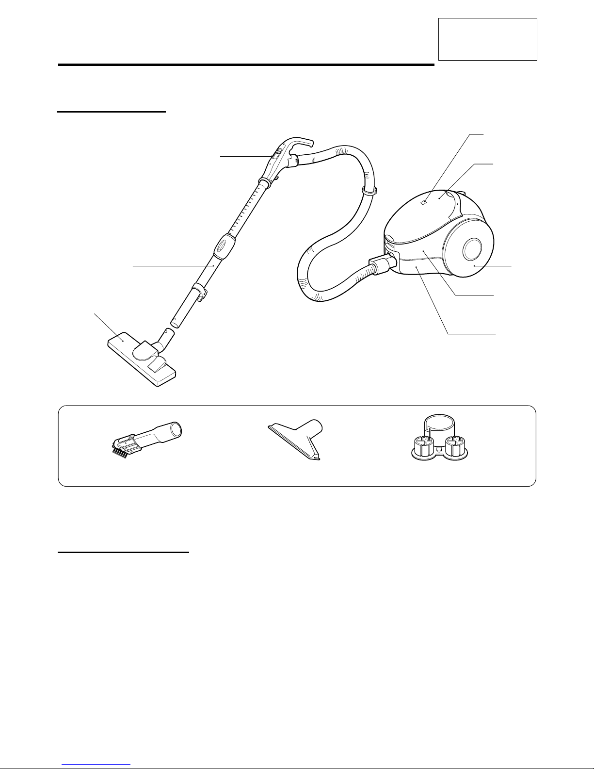
ATTACHMENTS
UPHOLSTERY NOZZLEBRUSH / CREVICE TOOL ACCESSORY HOLDER
Body cover
Body base
Handle
Dust Indicator
Filter cover
Flexible Hose ASS'Y
Telescopic Wand
Wheel
Rug/Floor Nozzle
3.1 MODEL 721.21195000, 20.21125
DESCRIPTION
Page 5

- 5 -
MODEL 721.21195000
721.21295000
20.21125
20.21325
• POWER SOURCE: ON RATING PLATE
• POWER CONTROL:
MAIN: SLIDE CONTROL ON HANDLE
• CAPACITY: 2
L
• CORD LENGTH: 5 m
• HOSE LENGTH: 1.8 m
• NET WEIGHT: 4.5 kg
• PACKING WEIGHT: 10.2 kg
• NET DIMENSION: 293
×
334× 243 (W× D× H)mm
• PACKING DIMENSION:
325 × 613 × 328(W × D × H)mm
• ATTACHMENTS
FLEXIBLE HOSE ASSY............................................. 1EA
TELESCOPIC WAND................................................. 1EA
Power-Mate ®..............................................................1EA
SANI-PUNCH NOZZLE...............................................1EA
BRUSH/CREVICE TOOL............................................ 1EA
UPHOLSTERY NOZZLE............................................ 1EA
ACCESSORY HOLDER ............................................. 1EA
Power Cord
(Not Shown)
Cord Reel
Button
Cord and
Cord Holder
Dust Indicator
Suction Inlet
Fitting Hook
Latch
Power
-Mate
®
Pawer
-Mate
®
Plug
Hose
Wand Holder
Wand Button
Telescopic
Wand
Cord Holder
Power Cord
Handle Button
Power-Mate
®
ON/OFF Switch
Slide Switch
ATTACHMENTS
UPHOLSTERY NOZZLE
BRUSH / CREVICE TOOL
ACCESSORY HOLDER
SANI-PUNCH NOZZLE
3.2 MODEL 721.21295000, 20.21325
DESCRIPTION
SPECIFICATIONS
Page 6
MODEL 721.21195000
721.21295000
20.21125
20.21325
4.DISASSEMBLY
• Almost all the parts of this vacuum cleaner can be
assembled with a screw driver and each connecting
component easily fits each other.
Disassemble one by one referring to the exploded view.
• If possible, don’t disassemble except for the necessary
parts. It is not necessary to disassemble the parts that
are not detailed in the exploded view.
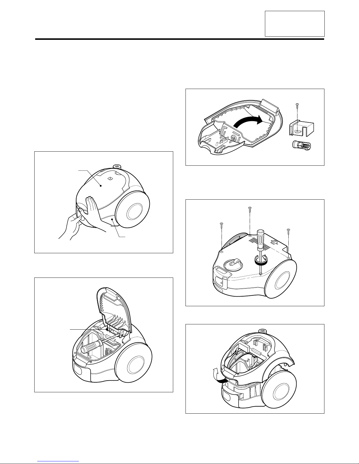
4.1 Filter Cover Assembly Replacement
l) Grasp body base and open filter cover.
2) Push the hinge side by inserting flat screw driver in
crack between hinge and body cover.
4.2 Indicator Assembly Replacement
4.3 Body Cover Assembly Replacement
1) Open the filter cover and remove the two screws and
remove the four screws fastening the body base.
2) Lift body cover in the direction of the arrow.
- 6 -
NOTE: Before attempting to service or adjust any part of the vacuum cleaner, disconnect the electrical power supply cord
from the wall outlet.
Filter Cover
Body Base
Hinge
Page 7
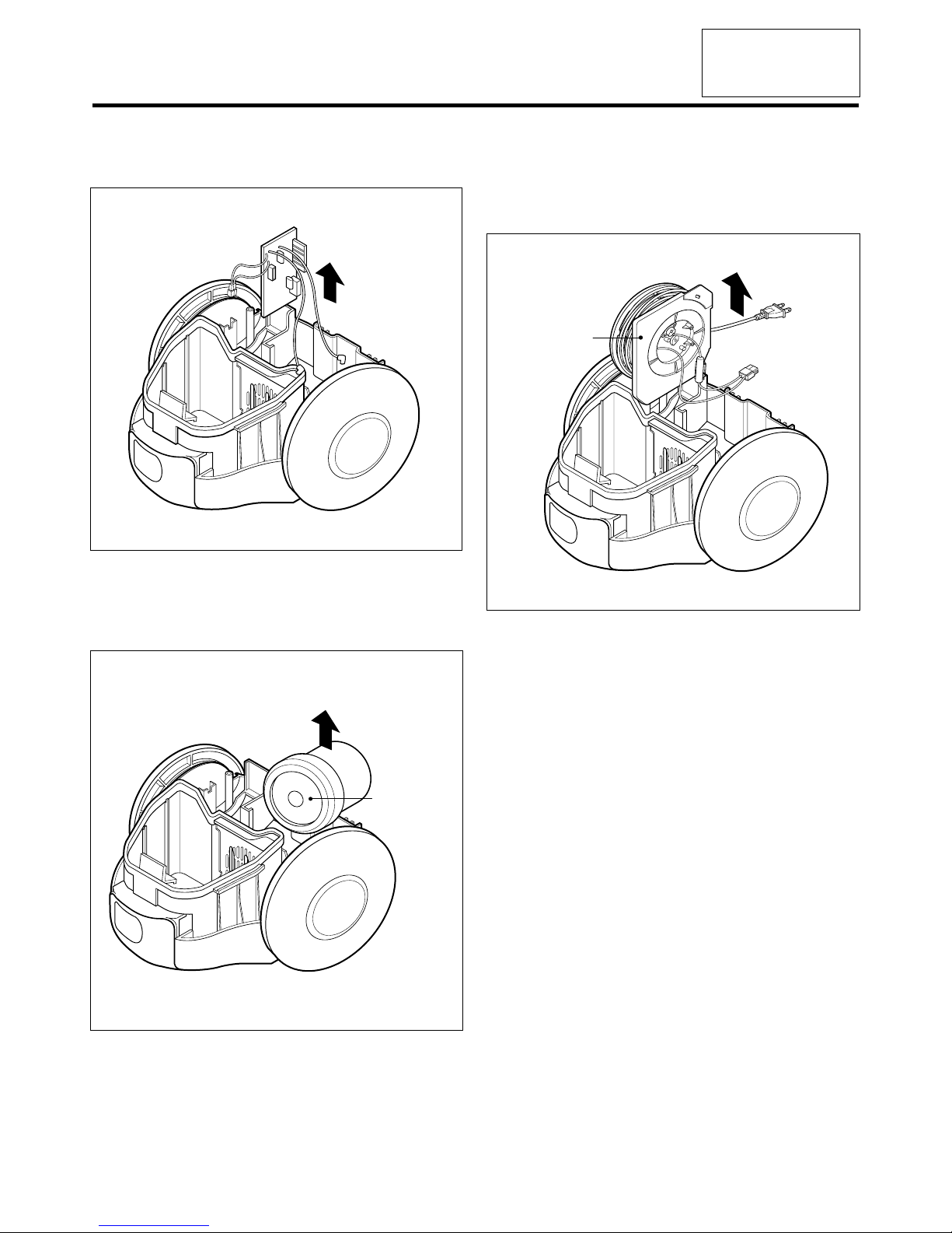
4.4 P.W.B ASS’Y Replacement.
1) Lift the P.W.B ASS’Y in the direction of the arrow.
4.5 Motor Assembly Replacement
• Lift the motor assembly in direction of the arrow after
stripping off the lead wires.
4.6 Cord reel assembly replacement
1) Lift the cord reel assembly from the body base in
direction of the arrow.
2) Strip off the lead wires.
- 7 -
MODEL 721.21195000
721.21295000
20.21125
20.21325
Motor ASS'Y
Cord Reel
ASS'Y
Page 8
- 8 -
MODEL 721.21195000
721.21295000
20.21125
20.21325
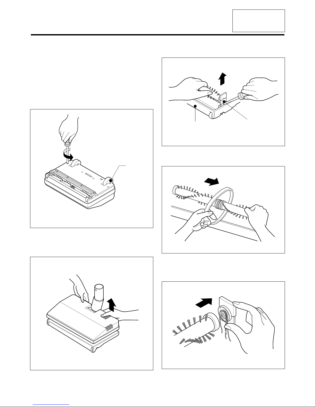
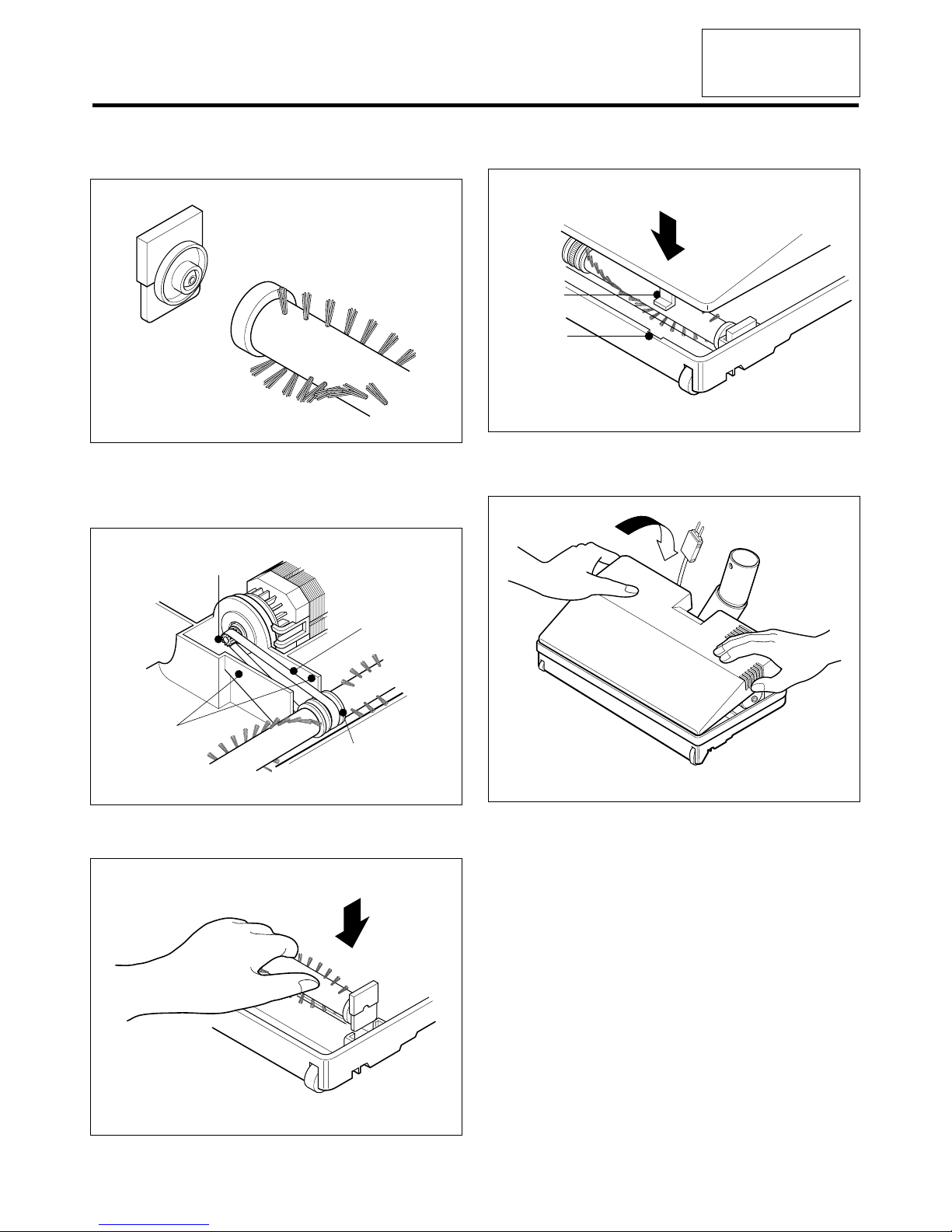
4.7 Belt Changing and Brush Cleaning
(ONLY MODEL 721.21295000, 20.21325)
• Disconnect cleaner from electrical outlet. Check and
remove hair, string and lint build-up frequently in the
Power-Mate®brush and brush support areas. If build-up
becomes excessive, disconnect Power-Mate® from
Telescopic wand.
TO REMOVE BELT
1) Turn power-Mate® upside down.
2) Unscrew the for Power-Mate® cover screws.
3) Turn Power-Mate®rear side up and tilt cover forward
from back until front snaps free.
4) Carefully insert and lift screwdriver at each brush support
to free brush from base.
4) Remove worn belt.
6) Slide brush supports off to check and clean brush
support areas. See BRUSH ASSEMBLY for picture of
complete brush assembly.
Wheel
Brush Support
Base
Page 9
- 9 -
MODEL 721.21195000
721.21295000
20.21125
20.21325
TO REPLACE BELT:
1) Install brush supports onto brush assembly.
2) Install new belt in belt groove on the brush assembly,
than over the motor shaft. Be sure belt in between the
belt guards.
3) Insert each support into its base slots.
4) Line up tabs on cover with slots inside the base.
5) Push cover and base together.
Base Slot
Cover Tab
Motor Shaft
Belt Guard
Belt Groove
Belt
Page 10
MODEL 721.21195000
721.21295000
20.21125
20.21325
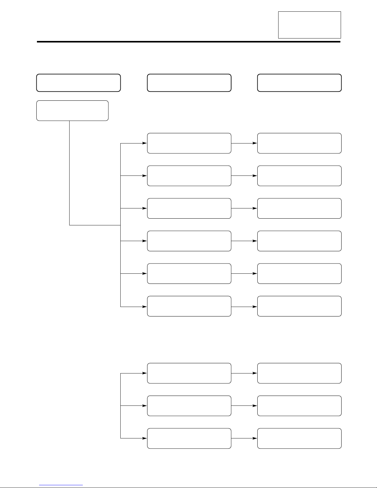
CHECKING CAUSE SOLUTION
Check the power source
Poor plug insertion
Power cord cut
Interior lead wire cut
Motor(stator armature) coil
cut or damaged
Poor contact carbon brush
defaced
Motor armature cut
Ball bearing defacement
Impeller hindrance
(Caused by foreign matters)
Insert again
Repair or exchange
Exchange the lead wire
Exchange the motor
Exchange or repair
Poor switch contact point Exchange the switch
Exchange the motor
Exchange the motor
Remove the foreign matters
Normal
5.TROUBLE SHOOTING
- 10 -
1) SWITCH ON BUT MOTOR DOES NOT TURN
2) SWITCH ON, MOTOR DOES NOT TURN BUT BUZZES
Page 11

MODEL 721.21195000
721.21295000
20.21125
20.21325
- 11 -
Carbon brush defaced
Motor armature cut
Foreign matters attached to
the impeller
Low voltage
Exchange the carbon brush
or the motor
Exchange the motor
Remove the foreign matters
Inquire to the power utility
company
Low rotation speed
Poor connection
Poor switch
Repair
Exchange the switch
Filter bag or cloth bag is filled
with inhaled foreign matters
Hose and extension wands are
clogged with foreign matters
Remove the foreign matters
in the hose or extension wands
The slide knob on the handle
is opened
Close the slide knob by
sliding it
Motor turns normally,
but suction power is weak
Remove the foreign matters
or exchange the filter bag or
clean the cloth bag
3) SWITCH OFF BUT MOTOR TURNS
4) WEAK SUCTION POWER
Page 12

MODEL 721.21195000
721.21295000
20.21125
20.21325
- 12 -
5) VIBRATION NOISES
6) RADIO, TV RECEPTION DISTURBANCE
7) IMPROPER HOSE OR NOZZLE CONNECTION
Poor cord, lead wire
Poor carbon brush rectified
Poor electric connector
or receiver
Poor capacitor
Exchange cord, lead wire
Exchange the carbon brush
or the motor
Repair the electric connector
or receiver
Exchange the capacitor
Bent connection parts
Poor connection
(Caused by foreign matters)
Exchange the parts
Remove the foreign matters
and reconnect
Loose parts
Unbalanced motor assembly
Foreign matters are attached
to the impeller
Poor carbon brush rectification
Secure firmly
Exchange or repair the motor
Remove the foreign matters
Exchange the carbon brush
or the motor
Armature is cut or foreign
matters attached
Exchange motor
Remove foreign matters
Page 13

MODEL 721.21195000
721.21295000
20.21125
20.21325
- 13 -
6.
WIRING DIA GRAM / SCHEMATIC DIA GRAM
SCHEMATIC DIAGRAM
M
C4
0.47µF
/AC
250V
C5
0.47µF
100V
C1
0.1µF
630V
R2
220
1/2W
R1
100
1/2W
R4
470
1/2W
Transformer
Fuse
T.S
R12
470K
R12-1
470K
R7
10K
R11
10K
R10
100
R6
22K
IC1
Opto-triac
TLP762
16
4
G
SS
_
+
T1
TRIAC
T2
2
VR1
VR1
20K
Q2
A1015
D5
1N4148
Q1
C3198
BD1
DF01M
R8
1K
R9
100
WH
BL
BL
BK
BL
BR
TS
P.W.B. ASS'Y
MOTOR
C/REEL ASS'Y
BR
BL
SLIDE VOLUME S/W
FLEXIBLE HOSE ASS'Y
FUSE
250V/15A
6.1 MODEL 721.21195000, 20.21125
WIRING DIAGRAM
Page 14

- 14 -
MODEL 721.21195000
721.21295000
20.21125
20.21325
SCHEMATIC DIAGRAM
M
M
R1
100
1/2W
C2
0.1µF
250V
C4
2200µF
16V
C4
0.47µF
Power
-Mate
®
S/W
D1
1N4007R610K, 5W
Power
-Mate
®
MOTOR
R4
33
1/2W
R2
33
1/2W
OPTION
R3
3.9K
1/2W
R9
100
R8
1K
R7
3K
Q1
C3198
R10
100K
OPTO-TRIAC
TLP762JF
6
4
1
2
MAIN MOTOR
R5 VR1
C3
T1
TRIAC
DIAC
T2
WH
WHWHWH
BKBK
PROTECTOR,
AGITATOR
Power-Mate
®
MOTOR
BL
Power-Mate
®
ON/OFF SWITCH
RD
WH
BK
BL
RD
BK
BL
BR
6
1
TS
P.W.B. ASS'Y
MOTOR
C/REEL ASS'Y
BL
BR
SLIDE VOLUME S/W
F/ HOSE ASS'YTELESCOPIC
WAND
Power-Mate
®
FUSE
250V/15A
6.2 MODEL 721.21295000, 20.21325
WIRING DIAGRAM
Page 15

- 15 -
MODEL 721.21195000
721.21295000
20.21125
20.21325
7.
PO WER AND CONTROL CIRCUIT BO ARD
7.1 MODEL 721.21195000, 20.21125
COMPONENT SIDE SOLDER SIDE
Page 16

- 16 -
MODEL 721.21195000
721.21295000
20.21125
20.21325
7.2 MODEL 721.21295000, 20.21325
COMPONENT SIDE
SOLDER SIDE
Page 17

MODEL 721.21195000
721.21295000
20.21125
20.21325
- 17 -
139202
146811
152302
149801
150401
144411
130401
168711
152301
139201
144801
149704
368011
TPL428
449801
135502
146601
TPL433
545805
135505
139206
152311
8.
EXPLODED VIEW/REPLA CEMENT PAR TS LIST
8.1 MODEL 721.21195000, 20.21125
EXPLODES VIEW
MODEL721.21195000
20.21125
Page 18

MODEL 721.21195000
721.21295000
20.21125
20.21325
- 18 -
146871
164111
10FZZ1
169301
MODEL 721.21195000
20.21125
Page 19

MODEL 721.21195000
721.21295000
20.21125
20.21325
- 19 -
335506
TPL328
349701
340261
235501
247661
335501
340361
236501
252302
239401
250202
249701
335211
MODEL721.21195000
20.21125
Page 20

- 20 -
MODEL 721.21195000
721.21295000
20.21125
20.21325
435507
444802
449701
449321
435001
TPL324
436501
452151
449401
652481
652031 649311
552491
649301
652012
MODEL 721.21195000
20.21125
Page 21

MODEL 721.21195000
721.21295000
20.21125
20.21325
- 21 -
REPLACEMENT PARTS LIST
MODEL721.21195000
20.21125
LOCATION NO. PART NO. DESCRIPTION REMARK
130401 3040FI1111D Base, Body
146601 4660FI1114D Wheel
135505 4660FI3238N Cover, Wheel
144801 3I23004B Locker, Filter
149704 4I23017A Spring
152301 5230FI3248A Filter, Motor Safety
135502 3550FI1113D Cover, Front
139206 4036FI3036A Gasket, Terminal
368011 3I23038G Harness, Single
139201 3920FI1115A Gasket, Dust
449801 3I23009L Block, Terminal
TPL428 1TPL0402818 Screw, Tapping
545805 4I22017F Roller
152311 5231FI2390J Filter Assembly, Paper 721.21195
152312 5231FI3018B Filter Assembly, Paper 20.21125
144411 4441FI3605J CASTER ASSEMBLY
146871 6411FI1071W Reel Assembly
164111 6411FI2422M Power Cord
10FZZ1 4I60037W Fuse, Time Delay
169301 6931FI3523E Thermostat
168711 6871FX2130C PCB Assembly, Main
235501 3070FI1110N Cover, Body
335501 3550FI1551K Cover, Filter
236501 3650FI2132N Handle, Carrier
340261 4026FI3234A Locker
349701 4970FI4260A Spring, Coil
250202 5020FI3233N Button, Cord Reel
249701 4I70024A Spring, Coil
247661 4766FI3251A Mop
239401 3940FI3252A Filter, Exhaust
335211 3I23019L Indicator Assembly
335506 3550FI3307G Cover, Indicator
340361 4036FI4074A Gasket
TPL328 1TPL0302818 Screw, Tapping
252302 5230FI3558A Filter, Exhaust
149801 4980FI3702A Damper, Motor
Page 22

LOCATION NO. PART NO. DESCRIPTION REMARK
146811 4681FI2373G Motor,AC
139202 3920FI3600C Damper,Motor Mount
150401 5040FI2449B Damper,Sound
152302 3940FI3646A Damper,Absorbing
452151 5214FI1453R Hose Assembly,Flexible
436501 3650FI1474C Handle,Grip
435501 3550FI1377X Cover,Grip
435001 3500FI3616X Panel,Switch
449321 4932FI2360C Hose Assembly,Connector
449401 4940FI3431A Knob,Control
TPL324 1TPL0302416 Screw,Tapping
444802 3I23013P Locker,Connector
449701 4I23028A Spring,Coil
435507 3550FI2358F Cover,Pipe
652012 5201FI2442A Pipe Assembly,Telescopic
649301 4930FI2231F Holder,Pipe
552491 5249FI1399A Nozzle Assembly,Floor
652481 5248FI2259C Nozzle,Upholstery
652031 3I22005N Brush Assembly,Dust
650581 3I22006M Nozzle,Crevice
649331 4930FI2378B Holder,Accessory
638901 3890FG1060A Box,Color
- 22 -
MODEL 721.21195000
721.21295000
20.21125
20.21325
MODEL721.21195000
20.21125
Page 23

MODEL 721.21195000
721.21295000
20.21125
20.21325
- 23 -
139202
146811
152302
149801
150401
144411
130401
168711
152301
139201
144801
449801
TPL428
149704
135502
146601
135505
TPL433
545805
139206
152311
368011
8.
EXPLODED VIEW/REPLA CEMENT PARTS LIST
8.2 MODEL 721.21295000, 20.21325
EXPLODES VIEW
MODEL 721.21295000
20.21325
Page 24

- 24 -
MODEL 721.21195000
721.21295000
20.21125
20.21325
146871
164111
10FZZ1
169301
MODEL 721.21295000
20.21325
Page 25

- 25 -
MODEL 721.21195000
721.21295000
20.21125
20.21325
335506
TPL328
349701
340261
235501
247661
335501
340361
236501
252302
239401
250202
249701
335211
MODEL721.21295000
20.21325
Page 26

- 26 -
MODEL 721.21195000
721.21295000
20.21125
20.21325
266011
236503
450202
236502
435001
442771
449401
435501
452151
652012
652481
652031 649311
444802
435507
649301
546603
MODEL721.21295000
20.21325
Page 27

- 27 -
MODEL 721.21195000
721.21295000
20.21125
20.21325
552493
552001
533003
435503
550201
MODEL 721.21295000
20.21325
Page 28

- 28 -
MODEL 721.21195000
721.21295000
20.21125
20.21325
552494
537402
564111
552013
537401
139205
546811
548202
548741
542801
535501
545803
545804
545801
545802
530401
558821
559731
344001
MODEL 721.21295000
20.21325
Page 29

- 29 -
MODEL 721.21195000
721.21295000
20.21125
20.21325
REPLACEMENT PARTS LIST
MODEL721.21295000
20.21325
LOCATION NO. PART NO. DESCRIPTION REMARK
130401 3040FI1111D Base, Body
135505 4660FI3238N Cover, Wheel
146601 4660FI1114D Wheel
144801 3I23004B Locker, Filter
149704 4I23017A Spring
152301 5230FI3248A Filter, Motor Safety
135502 3550FI1113F Cover, Front
139206 4036FI3036A Gasket, Terminal
368011 6801FI3256C Harness, Single
139201 3920FI1115A Gasket, Dust
449801 3I23009R Block, Terminal
TPL428 1TPL0402818 Screw, Tapping
545805 4I22017F Roller
152311 5231FI2390J Filter Assembly, Paper 721.21195
152312 5231FI3018B Filter Assembly, Paper 20.21325
144411 4441FI3605B Roller Assembly
146871 6411FI1071W Reel Assembly
164111 6411FI2422M Power Cord
10FZZ1 4I60037W Fuse, Time Delay
169301 6931FI3523E Thermostat
168711 6871FX2125A PCB Assembly, Main
235501 3070FI1110N Cover, Body
335501 3550FI1551K Cover, Filter
236501 3650FI2132N Handle, Carrier
340261 4026FI3234A Locker
349701 4970FI4260A Spring, Coil
250202 5020FI3233N Button, Cord Reel
249701 4I70024A Spring, Coil
247661 4766FI3251A Mop
239401 3940FI3252A Filter, Exhaust
335211 3I23019L Indicator Assembly
335506 3550FI3307G Cover, Indicator
340361 4036FI4074A Gasket
TPL328 1TPL0302818 Screw, Tapping
252302 5230FI3558A Filter, Exhaust
149801 4980FI3702A Damper, Motor
Page 30

- 30 -
MODEL 721.21195000
721.21295000
20.21125
20.21325
MODEL721.21295000
20.21325
LOCATION NO. PART NO. DESCRIPTION REMARK
146811 4681FI2373G Motor, AC
139202 3920FI3600C Damper, Motor Mount
150401 5040FI2449A Damper, Sound
239402 3940FI3646A Damper, Absorbing
452151 5215FI1316A Hose Assembly, Flexible
236502 3650FI1484A Handle, Grip
236503 3650FI1483A Handle, Grip
435501 3550FI2496A Cover, Grip
442771 6601FI3486M Slider Assembly, Volume
449401 4940FI3727A Knob, Control
266011 6601FI3472C Switch Assembly
450202 5020FI3765A Button, Control
435001 3500FI3619A Panel, Switch
435507 3550FI2501A Cover, Pipe
444802 3I23013P Locker, Connector
652012 5201FI1002A Pipe Assembly, Telescopic
649301 4930FI2231F Holder, Pipe
550201 5020FI4513B Button, Release
552494 5249FI1400A Nozzle Assembly, Power
564111 6411FI3298A Power Cord Assembly
537401 3740FI4259A Bush, Cord
535501 3550FI5001A Cover, Nozzle
545804 4580FI5003A Roller
545801 4580FI5001A Shaft
545802 4580FI5002A Roller
545803 4580FI5001B Shaft
552013 5201FI5001A Pipe Assembly, Suction
537402 3740FI5001A Mechanical Part, Unclassified
139205 3920FI5001A Damper, Motor
546811 4680FI5001A Motor, Unclassified
530401 3040FI5001A Base, Nozzle
558821 5882FI5001A Sweeper
548202 4820FI5001A Bumper, Nozzle
559731 5973FI5001A Shaft Assembly, Agitator
344001 4400FI5001A Belt
548741 4874FI5001A Eyelet
Page 31

- 31 -
MODEL 721.21195000
721.21295000
20.21125
20.21325
MODEL721.21295000
20.21325
LOCATION NO. PART NO. DESCRIPTION REMARK
542801 4280FI5001A Bearing, Ball
552493 5249FI1395J Nozzle Assembly, Quilt
435503 3550FI2462D Cover, Button
533033 3300FI4238B Plate, Beater
552001 5200FI2470A Pipe, Suction
652481 5248FI2259C Nozzle, Upholstery
652031 3I22005N Brush Assembly, Dust
650581 3I22006M Nozzle, Crevice
649331 4930FI2378B Holder, Accessory
638901 3890FG1060B Box, Color
Page 32

P/No. : 3828Fi9002H
 Loading...