

Sears 180.260250 Owner's Manual
Sears
owners
manual
MODEL NO.
180.260250
CAUTION:
Read Rules for
Safe Operation
and Instructi
Carefully!
ons
42" SNOW
ATTACHMENT
• ASSEMBLY
• ADJUSTMENT
e OPERATING
• MAINTAINENCE
PARTS LISTING
•
THROWER
M14-8002
Sears, Roebuck and Co., Chicago, Ill. 60684 U.S.A.
PRINTED IN U.S.A.
12/80
ATTENTION!! ASSEMBLY TIME
-
--------
----~
--
----~
The initial
tach
this
tractor
one half
time
Snow Thrower
required
to
assemble and at-
Attachment
will consume approximately o
(1-1/2)
hours. Future assembly times
to
ne
your
and
will be much less as you become familiar
with
the attachment.
TABLE
Assembly
Instructions
Adjustment Instructions
Operating
Maintenance
Parts
A
Instructions
Instructions
Listing
LOOK FOR THIS SYMBOL
PORANT SAFETY PRECAUTIONS. IT MEANS
ATIENTION! BECOME
TV IS INVO LVED.
OF
CONTENT
S
TO
POINT O
ALERT! YOUR SAFE·
20-23
UT
IM·
FULL ONE YEAR WARRANTY
For one year from the date of purchase, Sears ·
defect in material or workmanship in this trac
no charge.
If the tractor attachment is used
poses,
chase.
Warranty service is
simply
throughout the Unit
This warranty gives you specific legal rights, and you may a sc
have other rights which vary from state to state.
2
this
warranty applies only thirty da
available at your
c
onta
ctin g the nearest Sears s
ed States.
for comfT'
l"lo
<ore or
Sear, Roebuck and C
Sears Tower
sse
41
-3
Chicago,
w,..
e'"
:::
a O
ts
:,.
om
,.,..e
. at no charge. o;
IL
60684
~==~
~
e-
~::~:--s-:
'"
...
e...,<a our-
Lr.
e oate o' pur-
Service
Cen~e
o.
:
e:
...
RULES FOR SAFE OPERATION
1.
Know
the contro
OWNER'S
2. Do
not
allow
3. Do
distance away.
4.
Always
fitting
5. Keep
and the area being cleaned.
distract
6. Do
not
7.
Always
hand side.
8. Clear the work area of objects which
and
9. Disengage all attachment clutches and
before
10.
Disengage power
before leaving
11.
Disengage all power
and disconnect spark
before cleaning making an adjustme
allow
adults to operate
not
carry passengers. Keep children and pets a safe
wear substantial footwear. Do
clothing
your
you.
not
attempt
in the
get
thrown.
attempting
12. Disengage power
not in use.
attachment is in transport position.
13. Take
14.
all
unattended, such
lowering the attachments,
the parking brake, stopping
the key.
Do
not
stop or start suddenly when going
downhill.
15. Reduce speed
prevent
caution when changing
16. Do not
Choose a gear
without
move
17. Stay al
hazards.
18.
Do
highwa
shift
stopping and
throttle
ert for
not
drive
ys.
19. Exercise special care when removing snow around fixed
objects in
them. Never deliberately run tractor
over any foreign object.
ls
and how
MANUAL,
children to operate
that
could
eyes and
to operate
drivers
seat.
on
or
off
to
to
the
operator's
to
Drive
slowly when
possible precautions when leaving :he venicle
tipping
as
on
slopes and make
or
gears
low enough to negotiate
lever
to
holes in the terrain and
too close to creeks, ditches and public
order
to
to
stop
quickly,
without
get
mind
on
your
your
tractor
start
the engine.
attachments and stop the engine
to
snow
plug
attachments when
disengaging the power-
shifting
loss
of
direction
while
shifting
slow.
prevent the auger
the
proper Instruction.
caught
your
tractor, snow
Don't
tractor
from the operators.Jeft
position.
thrower
wire
(s)
front
into
the
engine, and
control. Exercise extreme
on
slopes.
going up
gears. To reduce speed,
READ
THE
vehicle. Do not
not
wear loose
in
moving parts.
thrower
let
other
interests
or
mower when
might
be picked
shift
into
neu
, stop the e
from spark plug(s)
nt
or
repa1rs.
traospon
or
rear
neutra
turns
or
down slopes.
from
or
mower Into
removing
gradua
the
other
ngine
.:-~
g
rrount
<aJ<e-off
l. settin
uphill
lly
slope
hidden
striking
up
tra
ed
or
or
to
or
20. Never
21. Never place hands
22. Use care when
23.
24.
25.
l
26. Keep the vehicle and
27.
g
28. Never store equ
29. To
30. The vehic le and attachments should be stopped and
31.
32.
shift
gears
until
tractor
comes
to
stop.
or
in the deflector (discharge chute)
parts
while
tractor
clear
of
discharge chute.
a.
Use
only
approved draw
b.
Limit
loads
c.
Do not
turn
d. Use counterweights
chains when suggested In
e.
Never run snow
speeds.
Watch
out for
When
using
any
material toward bystanders nor
vehicle
while
in operation.
Handle
a.
b. Never remove the cap
c.
condition, and keep
using Three Point
before making a
Keep all nuts, bo ts. and screws
and reta
is
a
spark.
enclosure.
leaves
inspected
and damage should be repaired before restarting and
operating the
Do not change the engine
speed
When using
follows.
a. Remove snow
b. Never make
c.
gasoline
Use approved gasoline cont
line
to a
running
indoors.
Open doors
exhaust fumes are
engine indoors.
in safe
building
reduce
light
runni
Shut the engine
Wipe
iner
springs
work
where fumes may reach an open flame
Allow
fire
or
excessive grease.
for
the
engine.
the vehicle
.
ng
if
feet near the snow
or
mower are
pulling
loads
or
using heavy
bar
hitch
to
those you can safely control.
sharply. Use care when backing.
or
wheel weights
this
thrower
traffic
when crossing
attachments, never
with
up spilled gaso
if
the engine is r..,.-r
Hucn
ny
repairs on attachment
ing conditiOn.
ipment
the engine to
hazard, keep the engine free of grass
damage
equipment.
on
any
the operator
off
into
heavy material
allow
care
it
is
highly
a ners.
of
the
or
hot e
ngire.
dange·ous Do not run the
attachments
sa'et
y devices in place.
remove attachments
'n place
ly
to
be sure the
with
gaso
coo
l before storing in any
after
striking
governor
with
snow
in
daylight
adjustments
must
when unclogging chute.
dismount
thrower
or
near any
running.
points.
owner's
or
near roadways.
direct
anyone near the
flammable.
iuel
tank
or
fill the fuel tank
~e
:19
in
good operating
tight
, all cotter pins
lin
e in the tank inside
a foreign object,
setti ngs
thrower
or
in good
while
moving
Always
equipment.
and
manual.
at
discharge
or
add gaso-
in the garage
from
or hitch.
equipment
or
, proceed
artificial
the engine is
to
do
so
auger,
keep
tire
high
of
When
hitch
or
over-
as
.
3
ASSEMBLY
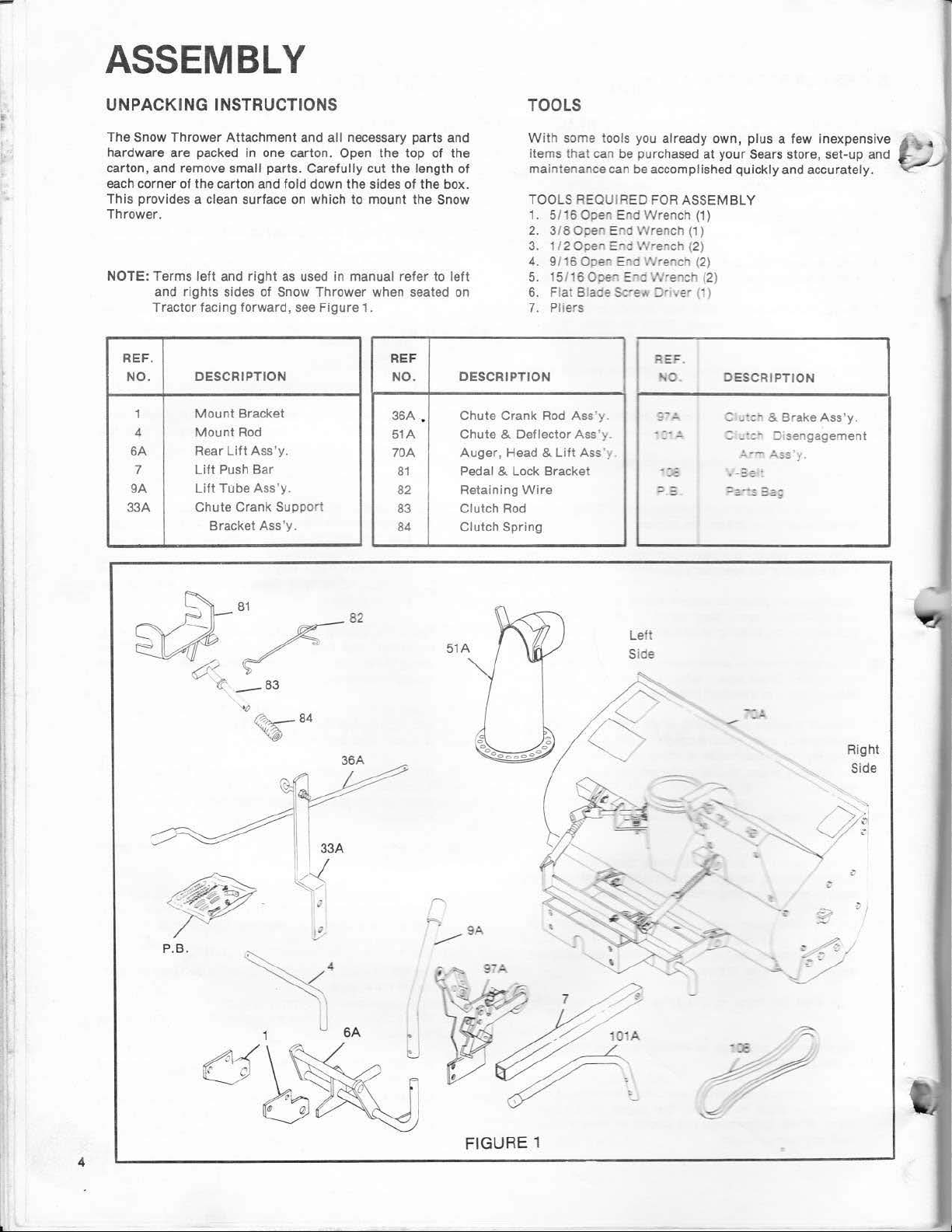
UNPACKING INSTRUCTIONS
The Snow Thrower Attachment and
hardware are packed
carton, and remove
each corner
This provides a
Thrower.
NOTE: Terms
REF. REF
NO.
6A
9A
33A
of
the
left
and rights sides
Tractor facing forward ,
DESCRIPTION
1
4
7
Mount
Mount
Rear
Lift
Lift
Chute Crank Supp
in
one carton. Open the
small parts. Carefully
carton and fold down the sides
clean surface
and
right
of
Snow Thrower when seated
Bracket
Rod
Lift
Ass'y.
Push
Bar
Tube
Ass 'y.
Bracket Ass
all
necessary parts and
cut
on
which to mount the Snow
as
used in manual refer to
see
Figure
1.
ort
'y.
TOOLS
top
of the
the lengt h
of
NO. DESCRIPTION
36A .
51
A
70A
81
82
83
84 Clutch Spring
of
the
box.
left
on
Chute Crank
Chute
Auger
Pedal & Lock Bracket
Retaining
Clutch
W
items that can be purchased
ma
TOOLS REQUIRED FOR ASSEMBLY
1. 5/16 Open End Wrench
2. 3/8 Ooen E
3. 1/2 Open e"O Vlrench (2)
4. 9/16 Open Eno
5. 15/1
6. Flat
7. Pliers
& Deflector Ass
, Head &
Wire
Rod
ith
some tools you already own, plus a few inexpensive
at
your Sears store, set-up and
int
enance can
600€
Blade Sc•e"'
Rod
Ass ·y.
Lift
Ass
'y.
'y
be
accomplished quickly and accurately.
(1)
rd
...
E.,c
Wrer"lch
'Nr
ench (2)
J'
.rench (2)
::Jr
.
REF.
.,0
~
-.!.
-
e•
(1)
(1
J
D
ESC
RIPTION
c
_:en
& Brake
:
_·:-
::J1sengag
.:.·-
~
.SS
Ass'y.
ement
i·
~
P.B.
·
~.,
Yf
_83
"()
~
~
84
;
·
J
6A
r
51
A
Le
ft
Side
-·
--
Right
Side
4
FIGURE 1
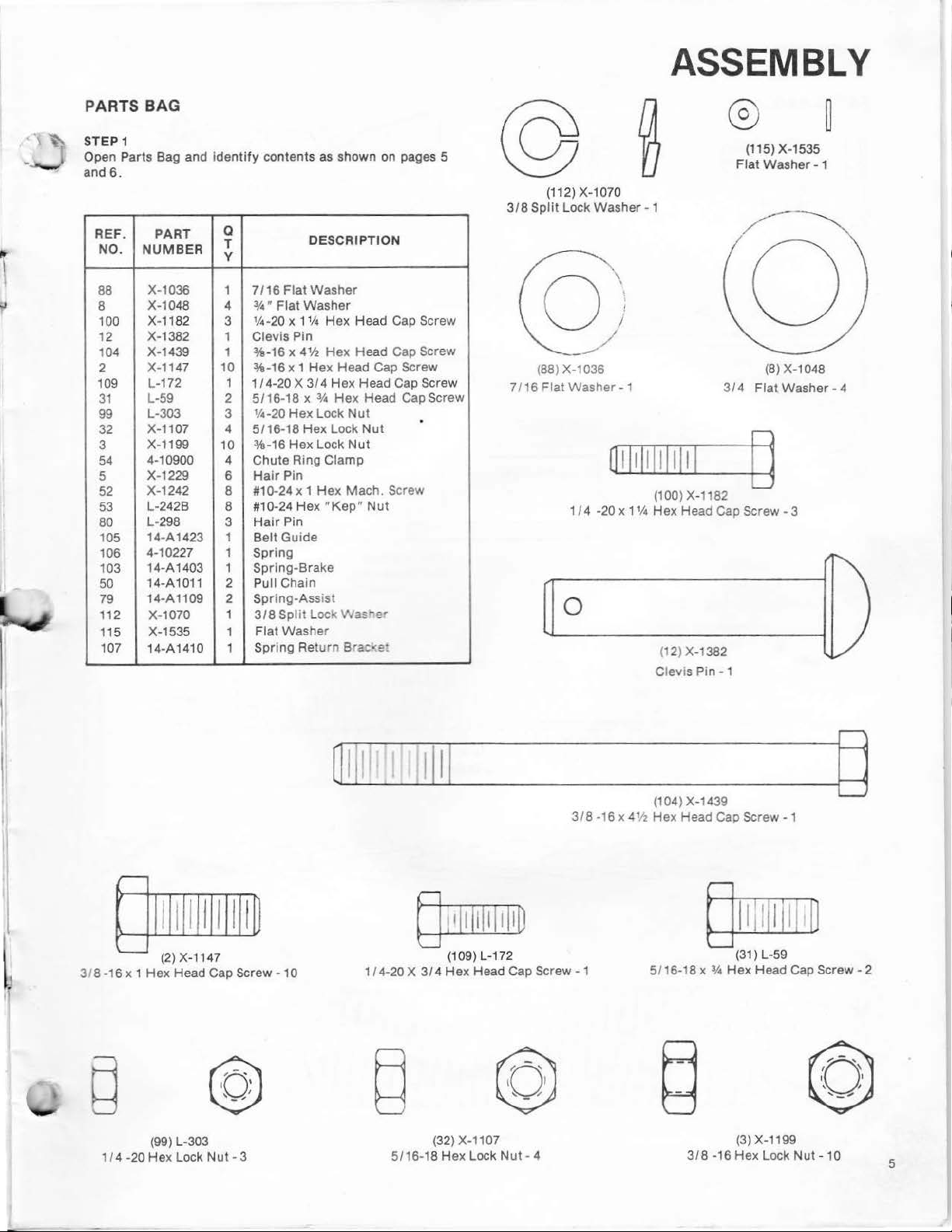
PARTS BAG
STEP 1
Open Parts Bag and
and
6.
REF. PA
NO. NU
RT
MBER
identify
a
T
y
contents as shown on pages 5
DESCRIPTION
318
(112) X-1070
Split
Lock
Washer
ASSEMBLY
®
(115) X-1535
Flat
Washer
- 1
~
- 1
88
8
100
12
104 X-1439 1
2
109
31
99
32
3
54
5
52
53
80
105
106
103
50
79
112
115
107
X-1036 1
X-1048
X-1182
X-1382 1
X-1147
L-172 1
L-59 2
L-303
X-1107 4
X-1199
4-10900
X-1229
X-1242
L-242B
L-298
14-A1423 1
4-10227
14-A1403
14-A1011
14-A1109 2
X-1070
X-1535
14-A1410
10
10
7/16
3,4 • Flat
4
1
.4-20 x
3
Clevis Pin
%-16 x 41/2
%-16
1 I 4-20 X
5/16-18 x 3.4
1.4-20
3
5/16-18
%-16
Chute
4
Hair
6
8
#1
0-24 x 1
#10-24
8
Hair
3
Belt
1
Spring
1
Spring-Brake
Pull Chain
2
Spr
1
3/8 Spli
Flat
1
Spring Ret
1
Flat
Washer
Washer
11.4
Hex
Hex
x 1
Hex
3/4
Hex
Lock
Hex
Hex
Lock
Ring
Clamp
Pin
Hex
Hex
"Kep•
Pin
Guide
ing-Assist
t Lock
Washe
r
urn
Head Cap Screw
Head Cap Screw
Head Cap Screw
Hex
Head Cap Screw
Hex
Head Cap Screw
Nut
Lock
Nut
Nut
Mach.
Screw
Nut
Wasrer
Brac-:e:
.
7116
(88)
Flat
X-1036
Washer
1/4
0
-20 x
-1
1114
(100) X-1182
Hex
Head Cap
(12} X-1382
Clevis Pin - 1
314
Screw-
(8) X-1048
Flat
Washer-
D
3
4
318-16 x 1
1/4-20
(2) X-1147
Hex
Head Cap Screw
(99) L-303
Hex
Lock
Nut-
@
3
-10
~
"--'---
11
~
1/4-20 X 3/4
dl
l
_
~
(109) L-172
Hex
Head Cap
___
318-16
Screw-
1
x 4
1/z
©
(32) X-1107
5116-18
Hex
Lock
Nut
- 4
(104)X-1439
Hex
Head Cap
~
5/16-18 x
3.4
318
(31) L-59
Hex
(3)X-1199
-16
Hex
_ g
Screw-
1
Head Cap
Lock
Nut-
Screw-
10
2
5
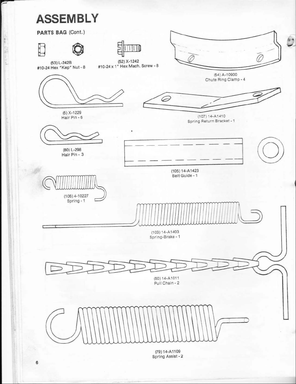
ASSEMBLY
PARTS BAG (Cont.)
(53) L-242B
#110-24
Hex wKep
• N
ut-
8
1110-24
~
(52) X-1242
x 1"
Hex
Mach .
Screw-
8
(54) A-10900
Chute
Ring Clamp - 4
(5) X-12
Hair
Pin-
29
6
~I
(80) L-298
Hair Pin-
{106) 4-10227
Spring-
3
1
{105) 14-A1423
Belt
(1
03) 14-A 1403
Spring-Brake-
Guide-
1
(
107
Spnng Reh
1
•4-A14•0
..
r., B
..
acl(et
-1
6
(50) 14-A
Pull
Chain-
14-A1109
{79)
Spring
1011
2
Assist - 2
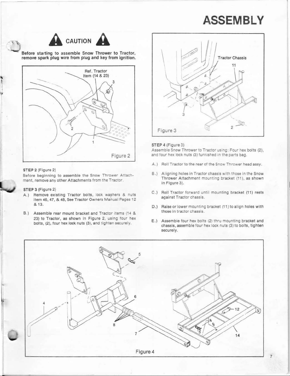
A CAUTION A
ASSEMBLY
Before
starting
to
assemble Snow Thrower
to
Trac
tor
remove spark plug wire from plug and key from ignition.
Ref. Tract
Item
(14
or
& 23)
Figure 2
STEP 2 (F
Befo
ment, remove any othe r
STEP
.)
A
B.) Assemble rear mount bracket and Tractor
igur
e 2)
re
beginning to assemble
Attac
3 (Fi
gure
2)
Remove existing Tractor bolts , lock Nashers &
46, 47
, & 48,
Item
&
13
.
23) to Tractor,
bolts,
(2)
, four hex lock nuts (3),
See
as
the Snow
hments from the - ·actor
Tractor Owners
shown In Figure 2 us
and
Thrower
Marua.
tighte'l
re~s
.,,
sec
Attac~>
nut
Pa;es
12
·
.!
&
'c...• r ex
..
•e y
,
Tract
or
Chassis
3
Ftgure 3
STEP 4 (Figure 3)
Assemble
and four hex lock nuts
A.
B.)
C.
s
) Roll Tractor forward
D.) Rai
E.
) Assemb le four hex
Snow Thrower to Tractor us ng.
) Roll Tractor to the rear
Ali
gning holes in Tractor chass•s w•tn those In the
Thrower
in Figure
against
those
chassis, assemble
securely.
se
or low
in
Attachment
Tr
trac
(3)
furnished m the parts bag.
of
the Snow - nrower head assy.
mount
ing
3).
until
mounting bracket
actor chass.s
er
mount ng bracket (11) to a
tor
chass s.
bo
ts 12 thru
'our
hex locrt nuts
brQCI(et
mounting bracket and
(3)
~our
hex bolts (2),
(1 1 ),
as
(11)
lign
holes
to bolts, tighten
Sno
w
shown
rests
with
Figure 4
7

ASSEMBLY
STEP 5 (Figure 4)
lift
Assemble
assembly.
A.)
Assemble
li
ft
bar
B.)
Place
lift
bar
rear
C.)
Raise
brackets
D.)
Insert mount rod (4) through holes and secure w
pin
E.)
Raise
mechanism
.)
Insert clevis pin (12) and secure
F
furnished in parts bag.
G.)
Assemble
hair
NOTE
: Location
H.)
Raise auger head asse
tube (9),
position •
podiy
•u
p lock
mechanism to Tractor and auger head
four
washers (8), furn ished
(7)
onto
lift lever
lift
assembly/lift
(7)
towards front and
of
Tractor.
lift
assembly (6), locating
(1)
and align holes, Figure 4.
(5)
furnished
lif
t bar
(7)
(14)
and align holes. Figure 4.
lift
tube
pin (5) Figure
it1
with
ion•,
is
cab (Figure 5).
lift
mechanism should oc n the up lock
.If
lift
remove washer
position.~
rod
(6)
as
shown
bar
(6
& 7)
lift
assembly
it
between rear mount
in
parts bag, Figu
locating
it
(9)
over
5.
used
without
mbly
mechanism does not
re
between bracket
lift
arm
(6)
cab Location
by
PtJ
(8)
as
required to obtain the
under
in
parts bag, and
in Figure
Tractor with
(6)
4.
of
with
hair
and secure
r.g
back on the
OCI(
towards
ith
front
pin
#2
is used
in
4.
hair
lift
with
lift
lock
(5)
STEP 6 (FigtJ•e c
Assemble V-be t
A .) Remove pu
Tractor
B.
) Remove hex
(See
C.)
Assemble Vguard (18), placmg '/-::-: • :-:_
D.) Place V-belt (108
Tractor
and locate in first
Owners
Page
grille.
•·::-
e
::::::-.:·
1
bo
~a-::
18ofya
belt
oo:
::-:•
'!a--~
...
·-·ac·-;·
·r,e :.::-...:-:- :
·-·:.;-
;•:>::"O:
---;:
...
~
~
'A~-=-
:.-,..
-::
-=~
·
"J:
:'
:-;
:•
~::achment
;_•e
1~
Page 6
se~--
-;
ruft'er
s :Vanua ).
..
ey
121)
:'
2"
- •
gnt
hand side
a·:-·o
-:
=-
et
engine pulley
to Tractor.
of
your
support
and be
of
lt
Figure 5
E.) Assemb le
hex
I
boltremoveo
bolt
Joel(
...
as-:· · ·:
(1~
'-·-
rS::: : =-::.:
!·:-:
:._-::
:.::; gutde
·
:::::.~
3ag replaci ng hex
(10
5) onto
Figure 7
_1
..
...::
-
--
......
"
5
STEP 7 (F
Assemble I
8
two
furnished in
pull
gure
It
charns
Pans
7
assis<s
~ r~t
Sa;
a"'C a ..
c
!Or nvs
,e•
·saa
"'"9
stab
zer springs using
a"'d two
hair
pins (5),
 Loading...