

Page 1
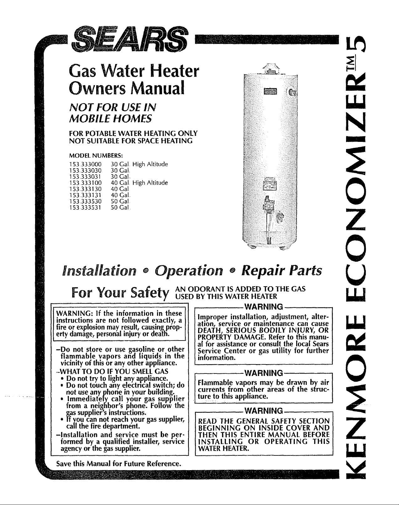
Gas Water Heater
OwnersManual
NOT FOR USE IN
MOBILE HOMES
FOR POTABLE WATER HEATING ONLY
NOT SUITABLE FOR SPACE HEATING
MODEl- NUMBERS"
153333000 30 Gal High Altitude
153,333030 30 Gal.
I $3,333031 30 GaL
153333100 40 Gal, High Altitude
153.333130 40 Gal
153333131 40 Gal.
153,333530 50 Gal
153.333531 50 Gal,
N
G
Installation + Operation + Repair Parts
For
WARNING: If the information in these
instructions are not followed exactly, a
fire or explosion may result, causin_ prop-
erty damage, personal inJury or dea_ti.
-Do not store or use gasoline or other
flammab!e vapors and liquid.s in the
vicinity of this or any other appliance.
-WHAT TO DO IF YOU SMELL GAS
Do not touch any electrical switch; do
i Do not try to light any appliance.
not useany phone in your building.
Immediately call your gas supplier
from a neighbor's phone. Follow the
I_as supplier s instructions.
• rf you can not reach your gas supplier,
call the fire department.
-Installation and service must be per-
formed by a qualified installer, service
agency or the gas supplier.
Your Safe usEDBYTHISWATER.EATER
tv ANODORANTISADDEDTOTHECAS
I
WARNING
Improper installation, adjustment, alter-
atmn, service or maintenance can cause
DEATH, SERIOUS BODILY INJURY, OR
PROPERTY DAMAGE. Refer to this manu-
al for assistance or consult the local Sears
Service Center or gas utility for further
information.
currents from other areas of the struc-
.......... WARNING t
Flammabl_e vapors may be drawn by air
ture t ° this appliance.
WARNING
READ THE GENERAL SAFETY SECTION
BEGINNING ON INSIDE COVER AND
THEN THIS ENTIRE MANUAL BEFORE
INSTALLING OR OPERATING THIS
WATER HEATER.
UJ
UJ
G
Save this Manual for Future Reference.
.._.__+! - _+L,3-_ .. --
Page 2

WARNING
Improper installation, adiustment0alteration, service or mainte-
nance can cause DEATH, SERIOUS BODILY INJURY, OR
PROPERTY DAMAGE_ Refer to this manual for assistance or
consultyour local Sears ServiceCenter for further information.
WARNING
At the time of manufacture thiswater heater was provided with
a combination temperature-pressure relief valve certified by a
nationally recognized testing laboratory that maintains periodic
inspection of production of listed equipment or materlars, as
meeting the requirements for Relief Valves and Automatic Gas
ShutoffDevices for Hot Water Supply Systems,and the latest
edition of ANSI Z21.22 and the code requirements of ASME. If
replaced, the valve must meet the requirements of local codes,
but not tess than a combination temperature and pressure relief
valve certified as meeting the requirements for Relief Valves
and Automatic Gas Shutoff Devices for Hot Water Supply
Systems,ANSI Z2t.22 by a nationally recognized testing labo-
ratory that maintains periodic inspection of production o-flisted
equipment or materials.
The valve must be marked with a maximum set pressure not to
exceed the marked hydrostatic working pressure of the water
heater (150 Ibs_/sq.in.) and a discharge capacity not less than
the water heater input rate as shown on the model rating
plate. (Electric beaters - watts divided by 1000 x 3415 equal
BTU/Hr. rate.)
Your local jurisdictional authority, while mandating the use of a
temperature-pressure relief valve compiyin_ with ANSI Z21.22
and ASME, may require a valve model di_erent from the one
furnishedwith the water heater.
Compliance wilh such local requirements must be satisfied by
the installer or end user of the water heater with a locally pre-
scribed temperature_pressure relief valve installed in the desig-
nated opening in the water heater in place of the factory fur-
nishedvalve.
For safe operation of the water heater, the relief valve must not
be removed from it's designatedopening or plugged.
The temperature-pressure relief valve must be i-nstalleddirectly
into tee fitting of the water heater designated for the relief
valve. Position the valve downward and provide tubing so that
any discharge will exit only within 6 inches above, or at any
distance below the structural floor. Be certain that no contact
is made with any llve electrical part. The discharge opening
must not be blocked or reducedin size under any circum-
stances.Excessivelength, over 30 feet, or use of more than four
elbows can cause restriction and reduce the discharge capacity
of the valve.
No valve or other obstruction is to be placed between the
relief valve and the tank. Do not connect tubing directly to
discharge drain unlessa 6" air gap is provided. To prevent bod-
ily injur-y, hazard to llfe, or prO)pettydamage, therelief valve
must be allowed to discharge water in quantltles should cir-
cumstances demand. If the _]ischarge pipe is not connected to
a drain or other suitable means, the water flow may cause
property damage; ........
The Discharge Pipe:
--Must not be smaller in size than the outlet pipe size of the
valve, or have any reducing couplings or other r'estrictions°
--Must not be plugged or blocked.
--Must be of material listed for hot water distribution.
_Must be installed so as to allow complete drainage of both
the temperature-pressure relief valve, and the dlscbarge pipe.
--Must terminate at an adequate drain.
--Must not have any valve between the relief valve and tank.
WARNING
WATER HEATERSEQUIPPED FOR ONE TYPE GAS ONLY: This
water heater is equipped for one type gasonly. Check lee model
rating plate near the gascontrol valvefor the correct gas.DO NOT
USETHIS WATER HEATERWITH ANY GAS OTHER THAN THE
ONE SHOWN ON THE MODEL RATING PLATE.Failureto usethe
correct gascan causeproblemswhich can result in DEATH, SERI-
OUS BODILY INJURY, OR PROPERTYDAMAGE. If you have any
questionsor doubtsconsultyour gassupplierorlocal utdlty.
WARNING
Afirecanstartif combustiblematerialssuchasclothing,cleaning
materlals_or flammableliquidsareplacedagainstor next to the
waterheater.
WARNING
INSTALLATIONSIN AREASWHEREFLAMMABLELIQUIDS
(VAPORS)ARELIKELYTO BEPRESENTORSTORED(GARAGES,
STORAGE,AND UTILITYAREAS,ETC):Flammablellquids (such
asgasoline,solvents,propane(LP)or butane,etc.),all of which
emitflammablevapors,maybeimproperlystoredorusedin such
areas.Thegaswaterheaterpdot fightormainburnercanIgnite
suchvapors,Theresultingflashbackand firecancausedeathor
seriousburnstoanyoneinthearea,aswellaspropertydamage.
If installation in suchareasisyouronlyoption,thentheinstalla-
llonmustbeaccomplishedinawaythat thepilotflameandmain
burnerflameareelevatedfrom theflooratleast18inches.While
thismay reducethechangesof flammablevaporsfrom a floor
spill being ignited,gasoffneand other flammablesubstances
shouldnever-bestoredor usedin thesameroomorareacontain-
inga gaswaterheateror otheropenflame or sparkproducing
appliance.
I_OTE:Flammablevaporsmaybe drawnby air currentsfrom
otherareasofthestructuretothe appliance,
WARNING
HOTTER WATER CAN SCALD: Water heatersareintendedtopro-
duce hotwater.Water heatedtoa temperaturewhich willsatisfy
clothes washing, dish washing, and other sanitizing needs can
scaldand permanentlyinjure you uponcontact.Some people are
more likely to be permanently injured by hot water than others°
Theseinclude the elderly, children, the infirm, or physically/men-
tally handicapped. If anyone using hot water in your home fits
into one of these groups or if there is a local code or state Jaw
requiring a certain_temperaturewater at the hot water tap, then
you must lake specialprecautions. In addition to usingthe lowest
possibletemperature settin_ that satisfiesyour hot water needs,
sometype of tempering dewce, suchas a mixing valve, shouldbe
usedat the hot water taps usedby these people or at the water
heater. Mixing valves are available at plumbing supply or hard-
ware stores, l_ollowmanufacturersinstructions-for installation of
the valves.Beforechangingthe factorysetting on the thermostat,
readthe "Temperature Regulation"section in thismanual.
WARNING
BEFORE LIGHTING [PROPANE (L,R)GAS WATER HEATER5]:
Propane(LR) gasis heavierthan air. Shouldtherebe a leak in the
system, the gaswill settle near the ground. Basements, crawl
spaces,skirted areasunder mobile homes(even when ventilated),
c|osetsand areasbelow ground level will serveaspocketsfor the
accumulationof this gas. Before attempting to light or religbt the
water heater'spilot or turning on a nearbyetectrlcal light switch,
be absolutelysurethere isno accumulatedgas in the area°Search
for odor ofgas by sniffing at ground level in the vicinity of the
apphance.If-odor is detected, follow stepsindicated at "ForYour
Safety"on the cover pageof thismanual then leave the premises.
Page 3
WARNING
Thiswaterheatermust not be installed directly on carpeting.
Carpetin_ must be protected by a metal or woodpanel beneatl_
the appliance extendin_ beyond the full width and depth of the
appliance by at ieast 3 inches (76.2mm) in anydirection, or if the
appliance is installed in an alcove or closet,the entire floor must
be covered by the panel. Failure to heed thiswarning may result
in afire hazard.
WARNING
A gaswater heater cannot operate properly without the correct
amount of air for combustion°Do not install in a confined area
suchasa closet, unless_ou provideair asshownin the "Locating
TEe New Water Heater section°Never obstruct the flow of ven-
tilation air. If you have any doubtsor questionsat all, call your
gascompany_Failure to provide the proper amount of combus-
tion air can result in a fire or explosionand can causeDEATH,
SERIOUS BODILY INJURY, OR PROPERTYDAMAGE.
WARNING
If this water heater will be usedin beauty shops,barber shops,
cleanln_ establishments,or self-service laundries with dry clean-
ing equipment, it is imperative that lhe water heater or water
heaters be installed so that combustion and ventilation air be
taken from ouLsidetheseareas. Refer to the "Locating The New
Water Heater" sectionof this manualand alsothe latest edition of
the National Fuel Gas Code, ANSI Z223.t, also referred to as
NFPA54 for specificsprovidedconcerningair required.
WARNING
VENT DAMPERS - Any ventdamper, whether it is operated ther-
mally or otherwise must be removed if its use inhibits proper
draftingof the water heater.
Thermally Operated Vent Dampers:Gas-fired water heaters hav-
ing thermal efficiency in excessofB0% may producea relatively
low flue gas temperature. Such temperatures may not be high
enough to properly open thermally operated vent dampers. Tl_is
woula causespillage of flue gasesandmay causecarbonmonox-
ide poisoning.
Vent dampers must bear evidence of certification as complying
with the |atest edition of American National Standard ANSI
Z21.68 (ANSI Z21.66 & 67, respectively,cover electrically and
mechanically actuated vent dampers)°Before installation of any
vent damper, consultyour local SearsService Center or the gas
utitity for further information°
WARNING
I. Theappliance and its individual shutoffvalve must be discon-
nected from the gassupplypiping systemduring any pressure
testing of the gas system at test pressures in excess of '/_
pound-per square inch (3_5kPa).
2. The appliance must he isolatedfrom the gassupplypiping sys-
tem by closingits individual manual shutoff valve during any
pressuretesting of the gas supplypiping system at tesl pres-
suresequaSor lessthan '/2poundper squareinch (3_5kPa).
WARNING
SOotbuitd_i_pindicatesa pi-0blemthat requires correction before
sooting can result in a fire or explosion causing DEATH, SERI-
OUS BODILY INJURY, OR PROPERTYDAMAGE_
WARNING
The water heater with draft hood installed must be properly
vented to a chimney which terminates outdoors. Never operate
the water heater unlessit is ventedto the outdoors and has ade-
quate air supply to avoid risks of improper operation, explosion
or asphyxiatlon_
WARNING
Obstructed or deteriorated vent systemsmay present a serious
heatth riskor asphyxiation.
WARNING
Chemical vapor corrosionof the flue and vent systemmay occur
if air for combustioncontainscertain chemical vapors°Spraycan
propellants, cleaning solvents,refrigerator and air conditioner
refrigerants, swimming pool cheml'cals, calcium and sodium
chloride, waxes, bleach, and processchemicalsare typical com-
poundswhich are potentlally corrosive°
WARNING
Minimum clearancesbetween the water heater and combustible
constructionare 1" at the sidesand rear, 4" at the front, and 6"
from the vent pipe. Clearance from the top of the jacket is 18"
on most models. Note that a lesserdimension may be allowed
on some models.Gaswater heatersacceptable for useon com-
bustible floors in an alcoveor closeL Refer to the label on the
water heater adjacent to the gascontrol vaive for ali clearances.
WARNING
HYDROGEN GAS:Hydrogengascan be produced in a hot water
systemthat has not beenused for a longperiod of time (generally
two weeks or more). Hydrogen gas is extremely flammable and
explosive_To prevent the possibilityof injury under these condi-
tions, we recommendthe hot water faucet be opened for several
minutes at the kitchensinkbeforeany electrical appliances which
are connectedto the hot water system are used(such as a dish-
washeror washingmachine). If hydrogengasispresent,there will
probablybe an unusual soundsimilar to air escapingthrough the
pipeas the hot water faucetisopened. There must be no smoking
or open flamenearthe faucetat the time it isopen°
WARNING
INSULATING JACKETS:When installing an external water heater
insulationjacketon a gaswater heater:
a_ DO NOT coverthe temperature-pressure relief valve°
b. DO NOT put insulationover any part of the top of the gas
water heater.
c. DO NOT put insulation over the gas control valve or gascon-
trol valve/burner cover,or any accessareas to the burner.
d. DO NOT let insulation around the gas water heater to get
within 8 inchesof the floor (air must get to the burner).
e. DO NOT cover or remove operating instructions,and safety
related warning labels and materials affixed to the water
heater.
Failure to heed this will result in the possibility of a fire or
explosion.
WARNING
Do not use this appliance if any part of it hasbeen under water.
Immediately call a SearsServiceTechnician to insp.ecttee appli-
ance and to replacethe gascontrol or any part of the burner sys-
tem which hasbeen under water.
CAUTION
WATER HEATERSEVENTUALLY LEAK:Installation of the water
heater must be accomplished in such a re;inner lhat if tEi_tank Or
any connections should leak, the flow of water will not cause
damage to the structure. When such locations cannot be avoid-
ed, a suitable drain pan should be installed under the water
heater. Drain pansare available at your local Searsstore. Such a
drain pan must be not greater than 1'/_inches deep: have amini-
mum length and width of at least2 inchesgreater than the water
heater dimensionsand must be piped to an adequate drain° The
pan must not restrict combustion air flow. Under no circum-
stances is the manufacturer or Sears to be hetd liable for any
water damagein connectionwith this water heater.
Page 4
General Safety.......................................................................................................................................................2_3
Table of Contents .............................................................................................................................................4
Introduction ...................................................................................................................................................................s
Specifications ..............................................................................................................................................................................s
Preparing for the New Installation ...........................................................................................5
Materials and Basic Tools Needed ..................................................................................................6
Materials Needed .......................................................................................................................................................................................6
Basic Tools ...................................................................................................................................................................................................6
Removing the Old Water Heater ..................................................................................................z
Locating the New Water Heater .....................................................................................................8-9
Facts to Consider About Location .............................................................................................................................................................8
Combustion Air and Ventilation for Appliances Located in Unconfined Spaces.........................................................................9
Combustion Air and Ventilation for Appliances Located in Confined Spaces...........................................................................9
Filling the Water Heater ......................................................................................................................................................................................12
Venting........................................................................................................................................................................................................12
Gas Piping .............................................................................................................................................................................................13
Installation Checklist ..........................................................................................................................................................................14
L 0 I1" ,r o
Ign[Ing ........................................................................................................................................................................................._s-16
Temperature Regulation ................................................................................................................................._z
For Your Information .................................................................................................................................._8.19
Start Up Conditions .....................................................................................................................................................................18
Condensat on ......................................................................................................................................................................................................18
Smoke/Odor ..........................................................................................................................................................................................18
Thermal Expansion ...............................................................................................................................................................................18
StrangeSounds ...................................................................................................................................................................................18
Operational Conditions ..................................................................................................................................................................18-19
Smelly Water ........................................................................................................................................................................................18-19
"Air" In Hot Water Faucets..............................................................................................................................................................19
High Temperature Shut Off System ..................................................................................................................................................19
Not Enough or No Hot Water .................................................................................................................................................................19
Water IsToo Hot ................................................................................................................................................................................19
Periodic Maintenance ....................................................................................................................................2o-2_
Venting System Inspection ...........................................................................................................................................................................20
Burner Inspection ...............................................................................................................................................................20
Burner Cleaning ........................................................................ 20
Housekeeping ..........................................................................................................................................................................................20
Temperature-Pressure Relief Valve Operation .....................................................................................................................................21
Tank (Sedment) C eaning .........................................................................................................................................................21
Draining ...........................................L.,,,,,,Z.......................:................................................................................................ 21
Dra n Va ve Washer Rep acement .....................................................................................................................................................21
Service ......................................................................................................................................................................................................21
Warranty ............................................................................................................................................................................................28
About Your Warranty ........................................................................................................................................................28
SearsInstallation Policy ..................................................................................................................................... 28
SearsInstallation Warranty ..........................................................................................................................................................28
Page 5
Thank You forpurchasingaSearswaterheater,
Properlyinstalled and maintained, it should give you yearsof
trouble freeservice.If you should decidethatyouwantthe new
water heaterprofessionallyinstalled by Searscontact the local
SearsServiceCenter or any Searsstore,They will arrangefor
prompt,quality installationby Searsauthorizedcontractors_
Abbreviations Found in This Instruction Manual
A_G.A. - American Gas Association
AN.S.I. - American National Standards Institute
N F PAo- National Fire Protection Association
WARNING
This gas-fired water heater is design certified by the
American Gas Association Laboratories under
American National Standards for Gas Water Heaters.
The installation must conform with this manual, Local
Codes and with the latest edition of ithe National Fuel
Gas Code, ANSI Z223.1.
This publication is available from ygur local govern-
ment or public library, gas company, or by writing
NFPA, Batterymarch ParkpQuincy, MA 02269.
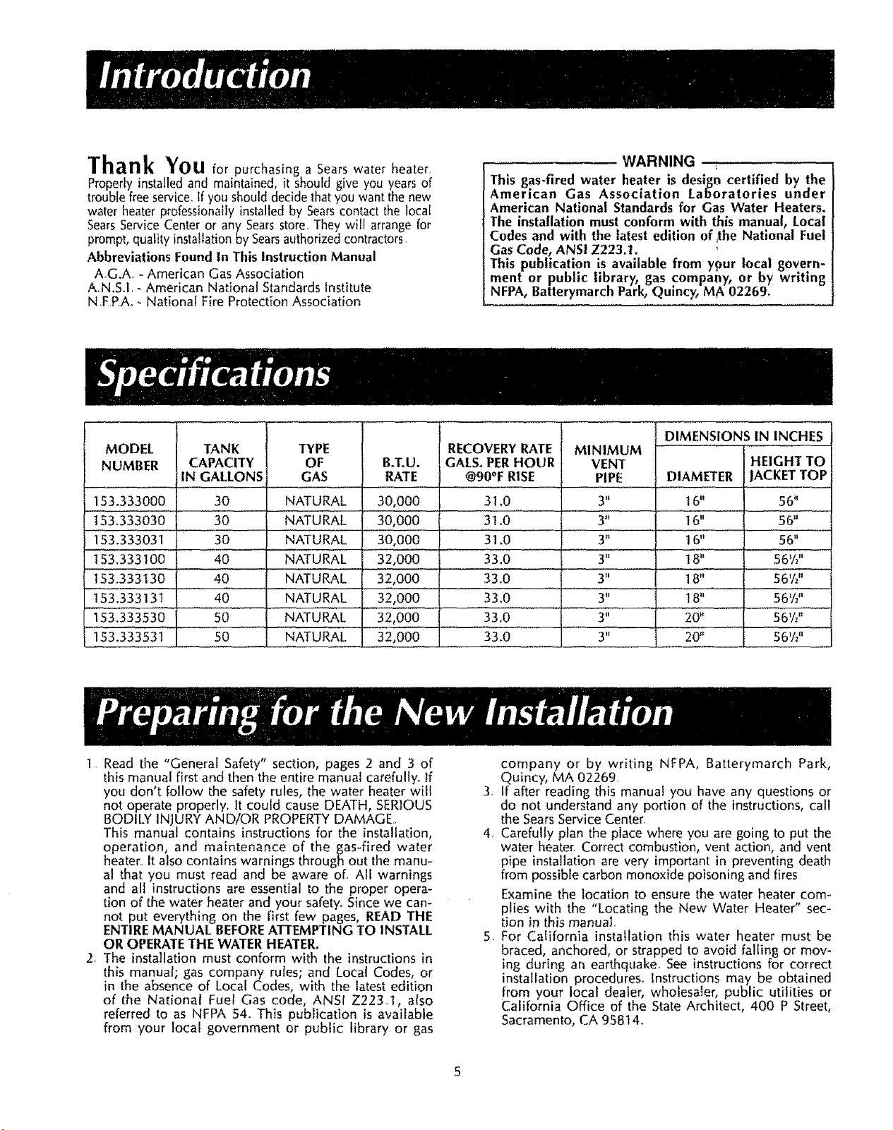
MODEL
NUMBER
153.333000 31.0
153.333030 31.0
153.333031 31.0
153.333100 33.0
153.333130 33.0
153.333131 33.0
is3.33353b......... [ 33.0
153.333531 [ 33.0
TANK
CAPACITY
IN GALLONS
30
3O
3O
40
40
40
50
50
TYPE
OF
GAS
NATURAL
NATURAL
'N'ATURAL
NATURAL
NATURAi_...........
NATURAL
NATURAL
NATURAL
B.T.U.
RATE
30,000
30,000
30,000
32,000
32,O00
32,000
32,00O
32,000
RECOVERY RATE
GALS. PER HOUR
@90°F RISE
1 Read the "General Safety" section, pages 2 and 3 of
this manual first and then the entire manual carefully.. If
you don't follow the safety rules, the water heater will
3, If after reading this manual you have any questions or
not operate properly. It could cause DEATH, SERIOUS
BODILY INJURY AND/OR PROPERTYDAMAGE,
This manual contains instructions for the installation,
4. Carefully plan the place where you are going to put the
operation, and maintenance of the gas-fired water
heater.,it also contains warnings through out the manu-
al that you must read and be aware of, All warnings
and all instructions are essential to the proper opera-
tion of the water heater and your safety. Since we can-
not put everything on the first few pages, READ THE
ENTIREMANUAL BEFOREATTEMPTING TO INSTALL
OR OPERATETHE WATERHEATER.
5. For California installation this water heater must be
2. The installation must conform with the instructions in
this manual; gas company rules; and Local Codes, or
in the absence of Local Codes, with the latest edition
of the National Fuel Gas code, ANSI Z223_I, also
referred to as NFPA 54. This publication is available
from your local government or public library or gas
DIMENSIONS IN INCHES
MINIMUM
VENT
PIPE
3"
3"
3';_......
3"
3"
3"
3"
3"
company or by writing NFPA, Batterymarch Park,
DIAMETER
16"
16"
16"
18"
18"
18"
20"
HEIGHT TO
JACKETTOP
56"
56"
56"
56%"
56V_"
56Y_"
56'1,"
56VI"
Quincy, MA 02269.
do not understand any portion of the instructions, call
the SearsService Center
water heater. Correct combustion, vent action, and vent
pipe installation are very important in preventing death
from possible carbon monoxide poisoning and fires
Examine the location to ensure the water heater com-
plies with the "Locating the New Water Heater" sec-
tion in thismanual
braced, anchored, or strapped to avoid falling or mov-
ing during an earthquake, See instructions for correct
installation procedures,. Instructions may be obtained
from your local dealer, wholesaler, public utilities or
California Office of the State Architect, 400 P Street,
Sacramento, CA 95814,
Page 6
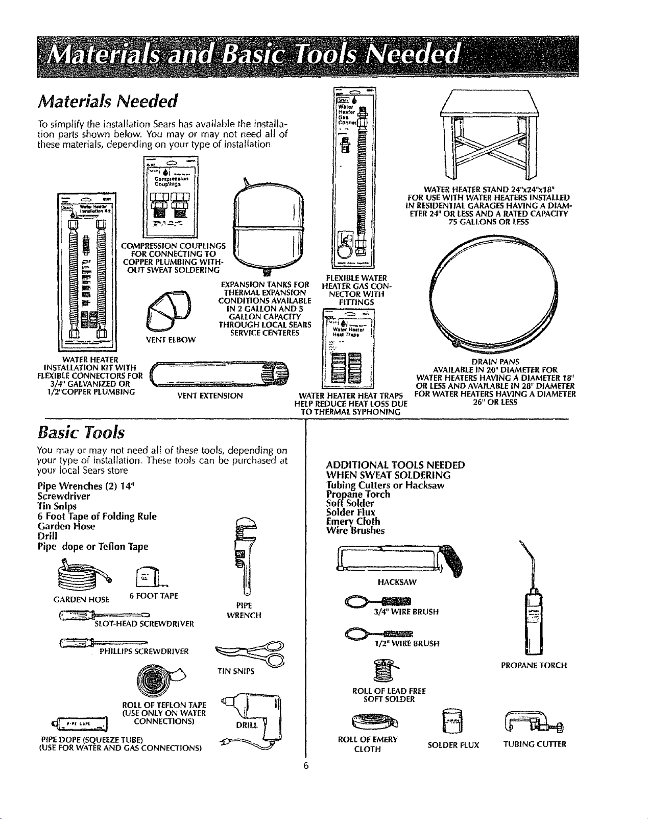
Materials Needed
To simplify the installation Searshas available the installa-
tion parts shown below_ You may or may not need all of
these materials, depending on your type of installation
I
/ \
WATER HEATER STAND 24"x24"x1B"
FOR USEWITH WATER HEATERSINSTALLED
IN RESIDENTIAL GARAGES HAVING A DIAM-
ETER24" OR LESSAND A RATED CAPACITY
75 GALLONS OR LESS
COMPRESSION COUPLINGS
COPPER PLUMBING WITH-
WATER HEATER
INSTALLATION KIT WITH
FLEXIBLECONNECTORS FOR
3/4" GALVANIZED OR
I/2"COPPER PLUMBING
Comprel_n
FOR CONNECTING TO
OUT SWEAT SOLDERING
O
VENT ELBOW
VENT EXTENSION
EXPANSION TANKS FOR
THERMAL EXPANSION
CONDITIONS AVAILABLE
IN 2 GALLON AND .5
GALLON CAPACITY
THROUGH LOCAL SEARS
SERVICECENTERES
Basic Tools
You may or may not need all of these tools, depending on
your type of installation,, These tools can be purchased at
your local Sears store
Pipe Wrenches (2) 14"
Screwdriver
Tin Snips
6 Foot Tape of Folding Rule
Garden Hose
Drill
Pipe dope or Teflon Tape
FLEXIBLEWATER
HEATER GAS CON-
NECTOR WITH
FITTINGS
Willr _IltlEI
Hil I *l'llJ_l
WATER HEATER HEAT TRAPS
HELPREDUCE HEAT LOSS DUE
TO THERMAL SYPHONING
ADDITIONAL TOOLS NEEDED
WHEN SWEAT SOLDERING
Tubing Cutters or Hacksaw
Propane Torch
Soft Solder
Solder Flux
Emery_ Cloth
Wire Brushes
AVAILABLE IN 20" DIAMETER FOR
DRAIN PANS
WATER HEATERSHAVING A DIAMETER 18"
OR LESSAND AVAILABLE IN 28" DIAMETER
FOR WATER HEATERS HAVING A DIAMETER
26" OR LESS
GARDEN HOSE
SLOT-HEAD SCREWDRIVER
PIPEDOPE (SQUEEZE TUBE)
(USE FOR WATER AND GAS CONNECTIONS)
6 FOOT TAPE
PHILLIPS SCREWDRIVER
ROLLOF TEFLON TAPE
(USEONLY ON WATER
CONNECTIONS)
PIPE
WRENCH
TIN SNIPS
HACKSAW
3/4" WIRE BRUSH
I/2" WIRE BRUSH
ROLL OF LEAD FrEE
SOFTSOLDER
ROLL OF EMERY
CLOTH
SOLDER FLUX
PROPANE TORCH
TUBING CUTTER
Page 7
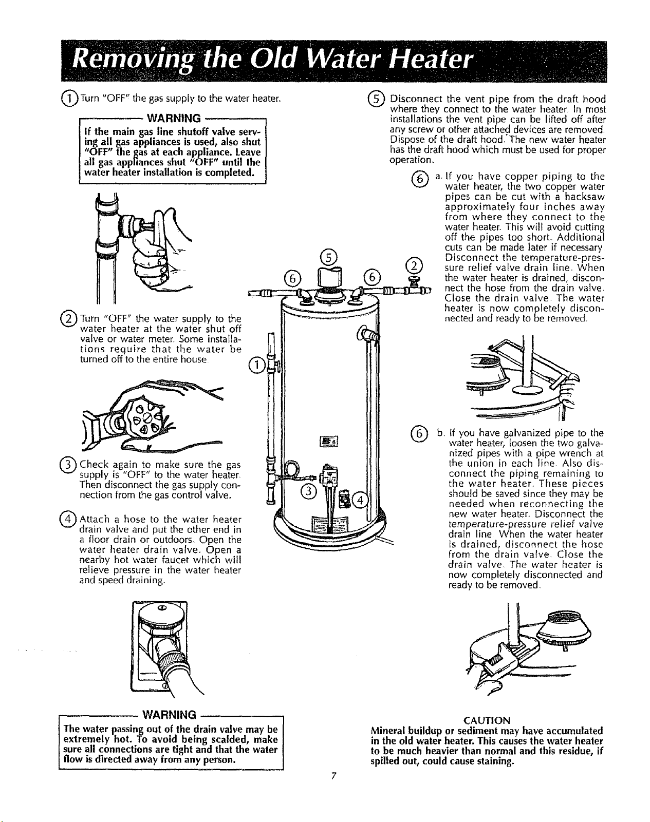
OTurn gassupply to water
ItOFF _" the the heater.
WARNING
If the main gas line shutoff valve serv- I
ing all gas appliances is used, also shut I
"OFF" the gas at each appliance. Leave
all gas appfiances shut aOFF" until the I
water heater installation is completed. I
t_O FFtt
Turn water supply to
water heater at the water shut off
valve or water meter Some installa-
tions require that the water be
turned off to the entire house
the
the
_.J
®
Q Disconnect vent pipe draft hood
where they connect to the water heater. In most
I
installations the vent pipe can be lifted off after
any screw or other attached devices are removed
Dispose of the draft hood,'The new water heater
has the draft hood which must be used for proper
operation,
Q a, If you have copper piping to the
the from the
water heater, the two copper water
pipes can be cut with a hacksaw
approximately four inches away
from where they connect to the
water heater. This will avoid cutting
off the pipes too short. Additional
cuts can be made later if necessary
®
®
Q Disconnect the temperature-pres-sure relief valve drain line, When
Q water heater is drained, discon-
the
nect the hose from the drain valve.
Close the drain valve The water
heater is now completely discon-
nected and ready to be removed.
Q Check again to make sure the gas
supply is "OFF" to the water heater,
Then disconnect the gas supply con-
nection from the gas control valve,,
Attach a hose to the water heater
drain valve and put the other end in
a floor drain or outdoors Open the
water heater drain valve° Open a
nearby hot water faucet which will
relieve pressure in the water heater
and speed draining.
i, WARNING
The water passingout of the drain valve may be
extremely hot. To avoid being scalded, make
sure all connections are tight and that the water
flow is directed away from any person.
If you have galvanized pipe to the
b,
water heater, loosen the two galva-
nized pipes with a pipe wrench at
the union in each line. Also dis-
connect the piping remaining to
the water heater. These pieces
should be saved since they may be
needed when reconnecting the
new water heater. Disconnect the
temperature-pressure relief valve
drain line When the water heater
is drained, disconnect the hose
from the drain valve. Close the
drain valve The water heater is
now completely disconnected and
ready to be removed,
CAUTION
Mineral buildup or sediment may have accumulated
in the old water heater. This causesthe water heater
to be much heavier than normal and this residue, if
spilled out, could causestaining.
Page 8
Facts to Consider About the
Location
You should carefully choose an indoor location for the
new water heater, because the placement is a very impor-
tant consideration for the safety of the occupants in the
building and for the most economical use of the appli-
ance This water heater is not for use in mobile homes or
outdoor installation.
Whether replacing an old water heater or putting the
water heater in a new location, the following critical
points must be observed,
I The location selected should be indoors as close as
practical to the gas vent or chimney to which the
water heater vent is going to be connected, and as
centralized with the water piping system as possible
The water heater, as all water heaters, will eventually
leak Do not install without adequate drainage provi-
sions where water flow will cause damage
CAUTION
WATER HEATERS EVENTUALLY LEAK: Installation of the
water heater must be accomplished in such a manner
that if the tank or any connections should leak, the flow
of water will not cause damage to the structure. When
such locations cannot be avoided, a suitable drain pan
should be installed under the water heater° Drain pans
are available at your local Sears store. Such a drain pan
must be not greMer than lY_ inches deep, have a mini-
mum length and width of at least 2 inches greater than
the water heater dimensions and must be piped to an
adequate drain. The pan must not restrict combustion air
flow. Under no circumstances is the manufacturer or
Sears to be held liable for any water damage in connec-
tion with this water heater.
WARNING
INSTALLATIONS IN AREAS WHERE FLAMMABLE LIQUIDS
(VAPORS) ARE LIKELY TO BE PRESENT OR STORED
(GARAGES, STORAGE AND UTILITY AREAS, ETC):
Flammable liquids (such as gasoline, solvents, propane (LP)
or butane, etc.) or other substances (such as adhesives,
etc.), all of which emit flammable vapors, may be improper-
ly stored or used in such areas. The gas water heater pilot
I!ght or main burner can ignite such vapors. The resulting
flashback and fire can causedeath or serious burns to any_
one in the area, as well as property damager
If installation in such are'as is your only option, then the
installation must be accomplished in a way teat the pilot
flame and main burner flame are elevated from the floor at
least 18 inches. While this may reduce the changes of
flammable vapors from a floor spill being ignited, gasoline
and other flammable substances should never be stored or
used in the same room or area containing a gas water
heater or other open flame or sparkproducing appliance.
Also, the water heater must be located and/(}r protected so
it is not subject to physical damage bya moving vehicle.
NOTE: Flammable vapors may-be drawn by air currents
from other areas of the structure to the appliance°
WARNING
Propellants of aerosol sprays and volatile compounds,
(cleaners, chlorine based chemicals,refrigerants,etc_) in
addition to being highly flammable in many cases, wilt
also changeto corrosivehydrochloric acid when exposed
to the combustion products of the water heater_ The
resultscanbe hazardous,and alsocauseproductfailure.
2 The location selection must provide adequate dear-
ances for servicing and proper operation of the water
heater
WARNING
This water heater must not be installed directly on carpet-
ing. Carpeting must be protected by a metal or wood panel
beneath the appliance extending beyond the full width and
depth of the appliance by at least 3 inches (76.2mm) in
any direction, or if the appliance is installed in an alcove
or closet, the entire floor must be covered by the panel.
Failure to heed this warning may result in a fire hazard.
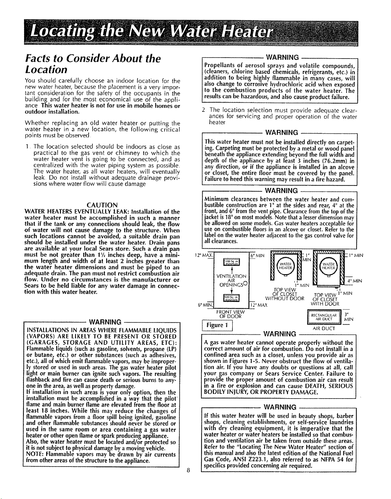
WARNING
Minimum clearances between the water heater and com-
bustible construction are i '_at the sides and rear, 4" at the
front, and 6" from the vent pipe. Clearance from the top of the
jackel is 18" on most models. Note that a lesser dimensmn may
be allowed on some models° Gas water heaters acceptable for
use on combustible floors in an alcove or closet° Refer to the
label on the water heater adjacent to the gas control valve for
all clearances.
t 2" MAX.
6" MIN
t
VENTILATION
AIR
OPENINGSU
6" M I"_<
Figure t ]
÷
÷
FRONT VIEW
OF DOOR
lIT" MAX WITH DOOR
TOPVIEW 'I"
OFCLOSET TOPVIEW MIN
WITHOUTDOOR OF CLOSET
WARNING
A gas water heater cannot operate properly without the
correct amount of air for combustion° Do not install in a
confined area such as a closet, unless you provide air as
shown in Figures 1-5. Never obstruct the flow of ventila-
tion air. If you have any doubts or questions at all, call
your_as company or Sears Service Center. Failure to
provide the proper amount of combustion air can result
m a fire or explosion and can cause DEATH, SERIOUS
BODILY INJURY, OR PROPERTY DAMAGE.
WARNING
If this water heater will he usedin beauty shops, barber
shops, cleaning establishments, or self-service laundries
with dry cleaning equipment, it is imperative that the
water heater or water heaters be installedso that combus-
tion and ventilationair be takenfrom outside theseareas.
Refer 1othe "LocatingTbe New Water Heater" sectionof
thismanualand also the latesteditionof the National Fuel
Gas Code, ANSI Z223_1, also referred to as NFPA 54 for
specifics providedconcerningair required.
1" MIN
R_CTANGULAR _'
AIRDUCT
4" MIN
Page 9
Combustion Air and Ventilation
for Appliances Located in
Unconfined Spaces
Unco_,fined Space is a space whose volume is not Jessthan 50
cubic feet per 1,000 Btu per hour of theaggregateinput rating
of all appliances installed in thatspace_Roomscommunicating
directly with the space in which the appliances are installed,
through openings not furnished with doors, are considered a
part of theunconfined space
In unconfined spacesin buildings, infiltration may be adequate
to provide air for combustion, ventilation and dilution of flue
gases,However, in buildings of tight construction (for example,
weather stripping, heavily insulated, cau]ked, vapor barrier,
etc.) additional air mayneedto be provided using the methods
described in Combustion Air and Ventilation for App lances
Located in Confined Spaces,b
Combustion Air and Ventilation
for Appl nces Located in
Confined Spaces
Confined Spaceis a spacewhose volume is lessthan 50 cubic
feet,per 1,000 Btuper hour of the aggregateinput rating of all
appliances installedin that space,
a.ALLAIRFROM INSIDE BUILDINGS:
(SeePageg Figure1, and Figure2 below)
The confined space shall be provided with two permanent
openingscommunicating directly with an additional room(s)
of sufficient volume so that the combined volume of all
spacesmeets the criteria for an unconfined space Thetotal
inputof all gas utilization equipment installed in the com-
bined space shall be considered in making this determina-
tion. Each opening shall have a minimum free area of one
squareinch per 1,000 8TU perhour of the total input rating
of a!l gas utilization equipment in the confined space, but
not lessthan I00 square inches. One opening shall com-
mence within 12 inches of the top and one commencing
within 12 inchesof the bottom of the enclosure
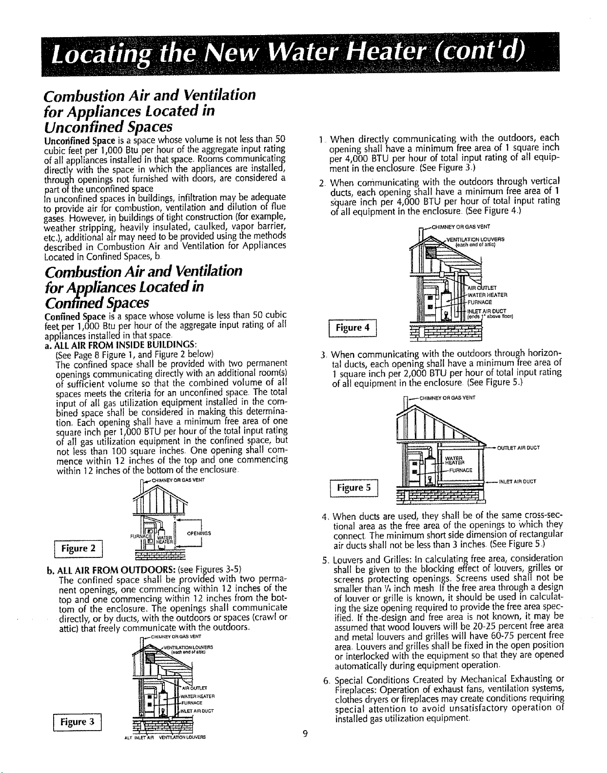
]. When directly communicating with the outdoors, each
opening shah have a minimum free area of t square inch
per 4,000 BTU per hour of total input rating of all equip-
ment in theenclosure tSeeFigure 3.)
2. When communicating with the outdoors through vertical
ducts, each opening shall have a minimum free areaof 1
square inch per 4,000 BTU per hour of total input rating
of all equipment in the enclosure (SeeFigure43
Figure4 t
t ! ,.l
3. When communicating with the outdoors through horizon-
tal ducts, each opening shall have a minimum freearea of
I squareinch per 2,000 13TUper hour of total input rating
of all equipment in the enclosure (SeeFigure5.)
TER
!1!" -tP
I Figure 5 J
FUN OPEN{_IGS
i---7
b. ALLAIR FROMOUTDOORS: (see Figures 3-51
The confined space shall be provided with two perma-
nent openings, one commencing within 12 inches of the
top and one commencing within 12 inches from the bot-
tom of the enclosure. The openings shall communicate
directly, or by ducts, with the outdoors or spaces(crawl or
attic) that freely communicate with the outdoors..
Figure 3 i
ALT IIILET _R VEh'_qL&T_O,b_ I*OUV'_q5
4, When ducts are used, they shall be of the same cross-sec-
tional area as the free area of the openings to _vhich they
connect. Theminimum short side dimension of rectangular
air ducts shall not be lessthan 3 inches (SeeFigure5.)
5,.Louversand Grilles: In calculating free area, consideration
shall be given to the blocking effect of louvers, grilles or
screens protecting openings. Screens used shall not be
smaller than %inch mesh If thefree area through a design
of louver or grille is known, it should be used in calculat-
ingthe size opening required to provide the freeareaspec-
ified,. If the-design and free area is not known, it may be
assumedthat wood louvers will be 20-25 percentfree area
and meta] louvers and grilles will have 60-75 percent free
area.Louversand grilles shall be fixed in the open position
or interlocked with the equipment sothat they are opened
automatically during equipment operation.
6 Special Conditions Created by Mechanical Exhaustingor
Fireplaces:Operation of exhaust fans,ventilation systems,
clothes dryersor fireplaces may create conditions requiring
special attention to avoid unsatisfactory operation of
installed gasutilization equipment.
Page 10

Water Piping
WARNING
HOTTER WATER CAN SCALD: Water heaters are
intendedto produce hot water. Water heated to a tem-
perature whmchwill satisfyclothes washing, dishwash-
ing, and other sanitizing nei_dscan scaldand perma-
nently inlure you upon contact. Some people are more
likely to be permanently injured by hot water than oth-
ers. These include the elderly, children, the infirm, or
physically/mentally handicapped, if anyone uslng hot
water in your home fits into one of these groupsor if
there is a local code or state law requiring a certain
temperature water at the hot water tap, then you must
take special precautions. In addition to using the low-
est possible temperature setting that satisfiesyour hot
water needs, some type of tempering device, such as a
mixing valve, should he usedat the hot water tapsused
by these people or at the water heater. Mixing valves
are available at plumbing supply or hardware stores.
Follow manufacturers instructions for installation of
the valves. Before changing the factory setting on the
thermostat, read the "Temperature Regulation" section
in this manual.
14
Look at the top cover of the water heater..The water
outlet is marked hot. Put two or three turns of teflon
tape around the threaded end of the threaded-to-sweat
coupling and around both ends of the ¥_"threaded nip-
ple, Using flexible connectors, connect the hot water
pipe to the hot water outlet on the water heater°
2"
Look at the top cover of the water heater. The cold
water inlet is marked coid_ Put two or three turns of
teflon tape around the threaded end of the threaded-
to-sweat coupling and around both ends of the ¥4"
threaded nipple_ Using flexible connectors, connect
the cold water pipe to the cold water inlet of the water
heater.
NOTE: This water heater isinsulated to minimize heat
loss from the tank. Further reduction in heat losscan
be accomplished by insulating the hot water lines
from the water heater.
INSTALLATION COMPLETED USING
SEARSINSTALLATION KIT SHUTOFF
FLEXIBLEWATER VALVE
-WARNING
This water heater shall not be connected to any heat-
ing systemsor component(s) now or previously used
wlth a non-potable water heating appliance.
WARNING o
Toxic chemicals such as used for treatment of boilers
or non-potable water heating appliances shall never be
introduced into a potable water heating system.
If a water heater is installed in a Closed water supply sys-
tem; such as one having a back-flow preventer, check
valve, water meter with a check valve, etc..., in the cold
water supply; means shall be provided to control thermal
expansion. Contact the local utility or local SearsService
Center on how to control this situation.
NOTE: To protect a_ainst untimely corrosion of hot and
cold water fittings, zt is strongly recommended that di-
electric unions or couplings 5e installed on this water
heater when connected to copper pipe,
The illustration shows the attachment of the water piping
to the water heater, The water heater is equipped with ¾
inch water connections,
CONN
HOT OUTLET COLD INLET
TO HOUSE WATER LINE
THRFADED TO
SWEAT COUPLING THREADED TO
NIPPLE NIPPLE
COLD
SWEAT COUPLING
It_ VALVE
NOTE: If using copper tubing, solder tubing to an
adapter before attachJ_ngthe adaptor to the colit water
inlet connection. Do not solder the cold water supply
line directly to the cold water inlet. It will harm the dip
tube and damage the tank.
10
Page 11

Temperature-Pressure Relief Valve
WARNING
At the time of manufacture this water heater was provided
with a combination temperature-pressure relief valve certi-
fied by a nationally recognized testing laboratory that main-
tains periodic inspection of production of listed equipment
or materials_ as meeting the requirements for Relief Valves
and Automatic Gas Shutoff Devices for Hot Water Supply
Systems, and the latest edition of ANS1 Z21.22 and the code
requirements of ASME If replaced, the valve must meet the
requirements of local codes, but not less than a combination
temperature and pressure relief valve certified as meeting
the requirements for Relief Valves and Automatic Gas
Shutoff Devices for Hot Water SupplySystems, ANSI Z21.22
by a nationally recognized testinglaboratory that maintains
periodic inspection of production of listed equipment or
materials°
The valve must be marked with a maximum set pressure not
to exceed the marked hydrostatic working pressure of the
water heater (150 Ibs.!sq_ in°) and a discharge capacity not
less than the water heater input rate as shown on the model
rating plate. (Electric heaters - watts divided by 1000 x 3415
equal BTU/Hr. rate.) .,
Your local jurisdictional authority, while mandating me use
of a temperature-pressure relief valve complying with ANSI
Z21.22 and ASME, may require a valve model dl_fferent from
the one furnished with the water heater,
ampliance with such local requirements must be satisfied
the installer or end user of the water heater with a locally
'escribed temperature-pressure relief valve installed in the
tesignated opening in the water heater in place of the facto-
'y furnished valve.
:or safe operation of the water heater, the relief valve must
not be removed from it's designated opening or plug.ged.
The temperature-pressure relief valve must be Installed
directly into the fittingof the water heater designated for the
relief valve. Position the valve downward and provide tubing
so thal any discharge will exit only within 6 inches above, or
at any distance below the structural floor. Be certain that no
contact is made with any live electrical part. The discharge
opening must not be blocked or reduced in size under any
circumstances. Excessive length, over 30 feet, or use of more
than four elbows can cause restriction and reduce the dis-
charge capacity of the valve.
No valve or other obstruction is to be placed between the
relief valve and the tank. Do not connect tubing directly to
discharge drain unless a 6" air gap is provided. To prevent
bodily Injury, hazard to life, or property damage, the relief
valve must be allowed to discharge water in quantities
should circumstances demand_ If the discharge pipe is not
connected to a drain or other suitable means, t_hewater flow
may cause property damage .........
The Discharge Pipe:
--Must not Ge smaller in size than the outlet pipe size of the
valve, or have any reducing couplings or other restriction.
--Must not be pluggedor blocked°
--Must be of material listed for hot water distribution°
--Must be installed so as to allow complete drainage of both
the temperature-pressure relief valve, and the discharge
plpe.
_Must terminate at an adequate drain.
--Musl not have any valve between the relief valve and tank°
WARNING
The temperature-pressure relief valve must be manual-
ly operated at least once a year, Caution should be
taken to ensure that (I) no one is in front of or around
the outlet of the temperature-pressure relief valve dis-
charge line, and (2) t_e water manually discharged will
not cause any bodily injury or property damage
because the water may be extremely hot,
If after manually operating the valve, it fails to complete-
ly reset and continues to release water, immediately
close the cold water inlet to the water heater, follow the
draining instructions, and replace the temperature-pres-
sure relief valve with a new one°
HOT
[]
FLOOR DRAIN
SHUTOFF COLD
VALVE
RE-PRESSURE
RELIEF VALVE
HARGE PIPE
(Do not cap or plug)
6" AIR GAP
RELIEF VALVE OPENING
ATTHETIMEOF MANUFACTURE,THISWATERHEATERWASPROVIDED
WITHACOMBINATIONTEMPERATURE-PRESSUREREUE_:VALVELISTED
ASCOMPLYINGWITHTHESTANDARDFORRELIEFVALVESANDAUTO-
MATICGASSHUTOFFDEVICESFORHOTWATERSUPPLYSYSTEMS,
ANSIZ2122. FORSAFEOPERATIONOF THEWATERHEATER,THE
RELIEFVALVEMUSTNOTBE REMOVEDFROMITSDESIGNATEDPOINT
OF INSTALLATIONORPLUGGED
YOURLOCALJURISDICTIONALAUTHORITY,WHILEMANDATINGTHEUSE
OFATEMPERATURE,PRESSURERELIEFVALVECOMPLYINGWITHANS!
Z21.22ANDASME,MAYREQUIREA VALVEMODELDIFFERENTFROM
THEONEFURNISHEDWITHTHEWATERHEATER
COMPLIANCEWITHSUCHLOCALREQUIREMENTSMUSTBESATISFIED
BYTHEINSTALLERORENDUSEROFTHEWATERHEATERWITHA
LOCALLYPRESCRIBEDTEMPERATURE-PRESSURERELIEFVALVE
INSTALLEDINTHEDESIGNATEDOPENINGINTHEWATERHEATER,
SEEMANUALHEADING--"TEMPERATURE,PRESSURERELIEFVALVES"
FORINSTALLATIONANDMAINTENANCEOFRELIEFVALVE,DISCHARGE
PIPEANDOTHERSAFETYPRECAUTIONS
1I
Page 12

Filling the Water Heater
CAUTION
Never usethis water heater unlessit is completely filled
with water. To prevent damageto the tank, the tank must
be filled with water_Water mustflow from the hot water
faucet before turning "ON" gasto the water heater.
To fill the water heater with water:
1, Close the water heater drain valve by turning the han-
dle to the right (clockwise) The drain valve is on the
lower front of the water heater.,
2 Open the cold water supply valve to the water heater
NOTE: The cold water supplyvalve must be left open
when the water heater ism use.
3, To insurecomplete filling of the tank, allow air to exit
by opening the nearest hot water faucet.. Allow water
to run untila constant flow is obtained., This will let air
out of the water heater and the piping.
4. Check all new water piping for leaks° Repairasneeded,
Venting
WARNING
VENT DAMPERS - Any vent damper, whether it is ol_erated
thermally or otherwise must be removed if its use Inhibits
proper drafting of the water heater.
Thermally Operated Vent Dampers: Gas-fired water heaters
having thermal efficiency in excess of 80% may produce a
relatively low flue Rastemperature. Such temperatures may.
not be high enough to properly open thermally operated
vent dampers. Thm_swould cause spillage of flue gases and
may cause carbon monoxide poisoning.
Vent dampers must bear evidence of-certification as com-
plying width the latest edition of the American National
Standard ANSI Z21.68 (ANSI Z21_66 & 67, respectively,
cover electrically and mechanically actuated vent dampers).
Before installation of any vent damper, consult the local
Sears Service Center or gas utility for further information.
--WARNING
To insureproperventingof thisgas-firedwater heater,the
correctventp=_pediametermustbeutilized_Anyadditionsor
deletionsof othergasappliancesona commonventwiththis
waterheatermay adverselyaffect the operationofthe water
heater_Consultthe localSearsServiceCenteror gasutilityif
anysuchchangesareplanned.
_or proper venting in certain installations, a larger diameter
vent pipe may be necessary. Due to great variances in
installations, unforeseeable by the manufacturer of the
water heater, you must consult your gas company to aid
you in determining the proper venting, for your.water heater.
from the vent tables in the latest edition of the National Fuel
Gas Code ANSI Z223 1,also referred to as NFPA54
Check the venting system for signs of obstruction or deterio-
ration and replace if needed,
The combustion and ventilation air flow must not be
obstructed
WARNING
Obstructed or deteriorated vent systemsmay present
serioushealth riskor asphyxiation_
14Place the draft hood legs in the receiving holes on the
top of the water heater,,The legs will snap in the holes
to give a tight fit.
2, Place the vent pipe over the draft hood, With the vent
pipe in position, drill a small hole through both the
vent pipe and draft hood Secure them together with a
sheet metal screw,
DRAFTHOOD _ [VENT,_I [ €
",_ _ S_RE_"_ DRAFT HOOD
_._VENT TO OUTDOORS
DRAFT HpO'D._ -OR ,_HIMNEY
' -WARNING !
The waterheaterwith draft hoodinstalledmusthe connect-[
ed to a chimneywhich terminatesto the outdoors°NeverI
operatethe water heaterunlessit is ventedto the outdoorsI
Iandhasadequateair supply toavoid risksof improperopera-[
[tion,explosionor asphyxiation. J
...... WARNING
Theventpipefromthe water heatermust be no lessthanthe
Idiameterof thedraft hoodoutlet onthewaterheater,andmust
Lslopeupwardtothechimneyatleast'1,inchper linear foot.
All vent gases must be completely vented to the outdoors
of the structure (dwelling), Install only the draft hood pro-
vided with the new water heater and no other draft hood
Vent pipes must be secured at each joint with sheet metal
screws_
CHIMNEY
PER LINEAR FOOT
VENTPIPEINSTALLATION
There must be a minimum of6"clearance betweensinglewall
vent pipe and any combustiblematerial Fill and sealany clear-
ance between single wall vent pipe and combustible material
with mortar mix, cement, or other noncombustible substance
Forother thansinglewall, follow vent pipe manufacturer'sclear-
ancespecifications Toinsurea tight fitof thevent pipe in a brick
chimney,sealaroundthevent pipe with mortarmix cement
WARNING
Failureto haverequired clearancesbetween vent piping
and combusbblematerial will resultin a fire hazard.
WARNING
Besure ventpipeisprol_erlyconnectedto preventescapeof
dangerousfluegaseswhich couldcausedeadlyasphyxiation.
WARNING
Chemicalvapor,corrosionof the flue and vent systemmay
occur if air for combustioncontainscertainchemicalvapors°
Spra_canpropellants, cleaningsolvents,refrigeratorandair
conditionerrefrigerants,swimmingpool chemicals,calcium
and sodium chloride,waxes,bleachand processchemicals
aretypicalcompoundswhich arepotentlal[ycorrosive.
12
,o
I
Page 13

Installation Checklist
BEFORE LIGHTING THE PILOT:
1_Check the gas lines for leaks,
a Use a soapy water solution, DO NOT test for gas
leaks using a match or open flame.
b Brush the soapy water solution on all gas pipes,
joints and fittings.
c, Check for bubbling soap, This means you have a
Leak Turn "OFF" gas and make the necessary
repairs.
d Recheck for teaks
e. Rinse off soapy solution and wipe dry.
2o Is the new temperature-pressure relief valve properly
installed and piped to an adequate drain? See
"Temperature-Pressure Relief Vatve" section
3 Are the cold and hot water lines connected to the
water heater correctly?See"Water Piping" instructions
in the "installing the New Water Heater" section.
4, Is the water heater completely filled with water? See
i'Filling the Water Heater" !nstructions in the
Installing the New Water Heater section,
5 Will a water leak damage anything? See the "Locating
the New Water Heater" section
VENT PIPE TO
OUTDOORS
OR CHIMNEY
• (
HOT
6., Is there proper clearance between the,water heater
and anything that might catch fire? See the
"Locating the New water Heater" section.
7. Do you have adequate ventilation so that the
water heater will operate properly? See
"Combustion Air and Ventilation" in the "Locating
the New Water Heater" section,,
8, Is the draft hood vent piping properly secured? See
"Venting" instructions in the "InstalLing the New
Water Heater" section,
9. Is there proper clearance between the vent pipe
and anything that might catch on fire? See
"Venting" instructions in the "Installing the New
Water Heater" section,
10. Is the vent pipe properly sloped and does the vent
terminate outdoors? See "Venting" instructions in
the "Installing the New Water Heater" section.
11. Do you need to call your gas company to check
the gaspipe and its hookup?
SHUTOFF VALVE
COLD
GAS SUPPLY
SHUTOFF VALVE -_
DRIP LEG_
(Sediment trap)
DRAIN VALVE
DRAFT HOOD
I" TEMPERATURE-PRESSURE
P
- DISCHARGE PIPE
(Do not cap or plug)
6" AIR GAP
FLOORDRAIN
RELIEFVALVE
MODEL RATING PLATE
14
Page 14

Piping,
WARNING
Make sure the gas suppliedis the same type listed on the
model rating plate, The inlet gas pressure must not exceed 14
inches water column [Y2pound per square inch (3o5kPa)]o
The minimum inlet gas pressure"listedon the model rating
plate is for the purposeoJ'input adjustment.
WARNING
If the gascontrolvalveissubjectedto pressuresexceedingt/_
pound-persquareinch (3.5kPa),thedamageto the gascon-
trolvalvecouldresultin afire or explosionfromleakl'nggas°
WARNING
If the maingaslineshutoff servingall gasappliancesisused,
alsoturn"OFF" thegasateachappliance.Leaveall gasappli-
ancesshutoffuntilthewaterheaterinstallationiscomplete°
A gas line of sufficient size must be run to the water
heater. Consult the latest edition of National Fuel Gas
Code ANSI Z223 1, also referred to as NFPA54 and the
gascompany concerning pipe size
There must be:
-A readily accessible manual shut off valve in the gas sup-
ply line serving the water heater, and
-A drip leg (sediment trap) ahead of the gas control valve
to help prevent dirt and foreign materials from entering
the gascontrol valve
-A flexible gas connector or a ground joint union between
the shutoff valve and control valve to permit servicing of
the unit
Be sure to check all the gaspiping for leaks before lighting
the water heater Use a soapy water solution, not a match
or open flame. Rinse off soapy solution and wipe dry
Standard Models are for installation up to 3,300 feet
above sea level.
High Altitude Models are for installation from 3,300 to
5,500 feet above sea level
If a standard model is installed above 3,300 feet or a high
altitude model is installed above 5,500 feet, the input rat-
ing must be reduced at the rate of 4 percent for each
1,000 feet above sea level. Contact your local Sears
Service Center or gas utility for further information
WARNING
WARNING
Use pipe joint compoundor teflon tape marked as being
resistantto theaction of petroleum [Propane(LP,)] gases_
SEDIMENT TRAP
A sediment trap shall be installed as close to the inlet of
the water heater as practical at the time of water heater
installation The sediment trap shall be either a tee fitting
with a capped nipple in the bottom outlet or other device
recognized as an effective sediment trap. If a tee fitting is
used, it shall be installed in conformance with one of the
methods of installation shown below.
Connectingthe gaspiping to the gascontrol valve of the water
heatercanbeaccomplishedby eitherof thetwo methodsshown
GAS PIPING WITH FLEXIBLE CONNECTOR
_._ GAS SUPPLY PIPING
MANUAL J_1'
SHUTOFFli_
VALVE
GROUND
UNION (Optional)
_ FLEXIBLE GAS CONNECTOR
LABELEDAS COMPLYING
WITHANSISTANDARDS
LOOP
CONTROL
GAS
VALVE
GAS PIPING WITH ALL BLACK IRON PIPE
TO GAS CONTROL
PIPING
SHUTOFF
MANUAL _GAS SUPPLY
VALVE
GROUND JOINTi_ /
UNION __
_[_ BLACKPIPE
GAS
CONTROL
VALVE
I The appliance and its gasconnection must be leak test-
ed bef(_replacing the appliance in operation.
........... WARNING. ......
The appliance and its individual shutoff valve must be discon-
nected from the gas supply piping systemduring any pressure
testing of that systemat test pressuresin excess of'h pound
per square inch (3_5kPa).
The appliance must be isolated from the gassupplypiping sys-
tem by closing its individual manual shutoff valve during any
pressuretesting of the gas supply piping system at test pres-
sures equal to or lessthan =/2pound per squareinch (3.5kPa).
......... WARNING ............. -
Contaminants in the gas lines may cause improper operation
of the gas control valve that may result in fire or explosion.
Before attaching the gasline be sure that all gas pipe is clean
on the inside. To trap any dirt or foreign material in the gas
supply line, a drip [eg (sometimes caJled a sediment trap)
must be incorporate([ in the pipings"The drip. leg must, be
readily accessible, install in accordance with the Gas
Piping_'section. Refer to the latest edition of the National
Fuel Gas Code, ANSI Z223_1, alsoreferred to as NFPA54.
13
Page 15

,'WARNING
BEFORE LIGHTING [PROPANE (LP.) GAS WATER
HEATERS]: Propane (L.P.) gas is heavier than air.
Should there be a leak in the system, the gas will settle
near theground. Basements, crawl spaces, skirted
areas under mobile homes (even when ventilated),
closets and areas below ground level will serve as
pockets for the accumulation of this gas. Before
attempting to light or rellght the water heater's pilot or
turning on a nearby electrical light switch, be absolute-
ly sure there is no accumulated gas in the area. Search
for odor of gas by sniffing at ground level in the vicini-
ty of the appliance. If odor is €tetected, follow the steps
indicated at "For Your Safety" on the cover page of
this manual, then leave the premises.
Lighting and operating instructions are located on front of
the water heater, above or to one side of the gas control
valve
--WARNING
AN ODORANT IS ADDED TO THE GAS USED
BY THIS WATER HEATER.
FOR YOUR SAFETY
IF YOU SMELL GAS:
1. Do not try to light any appliance.
2. Do not touch any electrical switch; do not use any
phone in your building.
3. Immediately call your gas supplier from a neighbor's
phone. Follow the gas supplier°s instructions.
4. If you cannot reach your gas supplier, call the fire
department.
I Figure 6 I
Figure 7 ]
WARNING
DO NOT force the gas control knob_ Use only your
hand to push it down to light the pilot, or to turn it to
"ON", "OFF" or "PILOT". Never use a tool such as a
lever, wrench or pliers° Do not hit or damage the knob.
A damaged knob may result in an explosion and seri-
ous injury. If you have problem turning the knob, Call
the gas supplier immediately.
CHECK FOR LEAKS
Be sure to check all gas pipes
, your for leaks before light-
ing your water heater.. Use a soapy water solution, not a
match or open flame. Check the factory gas fittings after
pilot is lit and gas control knob is still in "PILOT" position.
Then, check the fittings when the main burner is turned
"ON"- Use a soapy water solution for this, too.
_--_----__ INNERDOOR
_ OUTERDOOR
I Figure 9 ]
15
Page 16

FOR YOUR SAFETY READ BEFORE LIGHTING
WARNING
If you do not follow these instructions exactly, a fire or explosion
may result causing property damage, personal injury or loss of life.
A. Thisappliancehasa pilotwhichmustbelightedby
hand,Whenlightingthepilot,followtheseinstructions
exactly.
B.BEFORELIGHTINGsmellall aroundtheappliancearea
for gas. Be sureto smellnextto the floor because
somegasisheavierthanairandwillsetUeonthefloor.
WHATTODOIFYOUSMELLGAS
Donottryto lightanyappliance.
Do not touchany electric switch;do not use any
phoneinyourbuilding.
, Immediatelycallyourgassupplierfrom a neighbor's
phone°Followthegassupplier'sinstructions_
LiGHTiNG iNSTRUCTIONS
1oSTOP!Readthesafetyinformationaboveonthislabel.
2.Removeouterdoor.
3. Set the thermostatto lowestsettinqby turningthe
watertemperaturedialclockwise,(( _,)toitslowest
temperaturesetting(witharrowondial)as shown.DO
NOT FORCE.
4oTurngascontrolknobclockwlse_d'l to "OFF'*posi-
tion. Knobcannotbe turnedfrom "PILOT" to "OFF"
unlessknobisdepressedslightly.DO NOT FORCE.
(Figure6,page15)
5_Waitfive (5) minutesto clearout anygas°If youthen
smellgas,STOP!Follow"B" in thesafetyinformation
aboveon this label.If youdon'tsmellgas,go to the
nextstep°
6oRemove(oropen)innerdoorlocatedbelow the gas
controlunit,(Figure9, page15)
7.Findpilot-followmetaltubefromgascontrol.Thepilot
islocatedontherighthandsideoftheburner°
PILOT BURNER _THERMOCOUPLE
8.Ifyoudon't smell gas,turn knobon gascontrolcounter
c!ockwise_@ to"PILOT"position. (Figure7, page15)
• If you cannotreachyourgassupplier,call the fire
department.
C.
Useonlyyourhandtopushin or turnthegascontrol
knob.Neverusetools.If theknobwillnot pushinor
turnbyhand,don'ttrytorepairit, calla qualified ser-
vicetechnician.Forceorattemptedrepairmayresult
in afireorexplosion.
D_
Donotusethisapplianceif anyparthasbeenunder
water.Immedtzitelycall a qualified servicetechnician
toinspecttheapplianceandtoreplaceanypartofthe
controlsystemandany gascontrolwhichhasbeen
underwater.
9oPush in control knoball the way and hold down.
Immediatelylightthepilotwitha match.Continueto
holdcontrolknob in for aboutone (1) minuteafter
thepilotis lit. Releaseknoband itwill pop backup.
Pilotshouldremainlit. If it goesout,repeatsteps 3
through8.
• If knobdoesnotpopupwhenreleased,stopand
immediatelycallyour servicetechnicianor gas
supplier.
' If the pilot will not stay lit after several tries,
depressandturnthegascontrolknobclockwise
@ _ to"OFF''andcallyourservicetechnician
or gassupplier.(Figure6,page15)
10.Replace(or close)innerdoor°Replaceouter doorif
doordoesnotcovergascontrolon/offknobor tem-
peratureadjustmentknob.(Figure9, page15)
1!. Atarmslengthaway,turngascontrolknobcounter-
clockwise _ to the full "ON" position.
WARNING Do not use gas control knob to reg-
ulate gas flow. (Figure8, page15)
124At armslengthaway,set thethermostatto desired
setting.Themark( '_') HOTindicativeof approximate
120°Fis preferredstartingpoint, Somelocal laws
mayrequirea lowerstartingpoint.If hotterwateris
desired,seeinstructionmanualand"warning" below_
13oReplacetheouterdoorifnotreplacedinstep10.
WARNING
Hotterwaterincreasesthe riskof scald injury°Beforechangingtemperaturesettingsee instructionmanual
TO TURN OFF GAS TO APPLIANCE
1oSetthethermostatto lowestsettingby turningthe 2.Turngascontrolknobclockwise_ 1 to"OFF"posi.
watertemperaturedialclockwise(F-'_) to its lowest tion.Knobcannotbe turnedfrom"PILOT"to "OFF"
temperaturesetting(witharrowondial)as shown.DO unlessknobisdepressedslightly_DO NOT FORCE.
NOT FORCE, _ (Figure6,page15)
3_Replaceouterdoor(if removed)_
]6
Page 17

Due to the nature of the typical gas water heater, the
water temperature in certain situations may vary up to
30°F higher or lower at the point of use such as, bathtubs,
showers, sink, etc,
This means that when the temperature adjustment dial is
set at the mark approximating 120° F, the actual water
temperature at any hot water tap could be as high as
150°F or as low as90°E
Any water heater's intended purpose is to heat water_ Hot
water is needed for cleaning (bodies, dishes, clothing).
Hot water will present a scald hazard. Depending on the
time element, and the people involved (normal adults,
children, toddlers, elderly, infirm, etc.) scalding may
occur at different temperatures..
WARNING
HOTTERWATERCAN SCALD:Water heatersareintendedto
producehot water. Water heated to a temperaturewhich
will satisfyclotheswashing, dishwashing,andothersanitiz-
ingneedscanscaldand permanentlyinjureyou uponcon-
tact. Somepeopleare morelikelyrobe permanently injured
by hotwater thanothers.Theseincludetheelderly,children,
the infirm, or physically/mentallyhandicapped,if anyone
usinghot waterin yourhomefits into oneofthesegroupsor
if thereis a localcodeor statelaw requiringa certaintem-
peraturewaterat the hot water tap, thenyou musttakespe-
cial precautions.In additionto usingthelowest possibletem-
perature setting that satisfiesyour hot water needs,some
typeof temperingdevice,suchasa mixingvalve,shouldbe
usedat the hot water taps usedby these peopleor at the
waterheater.Mixingvalvesare availableat plumbing supply
or hardwarestores.Follow manufacturersinstruct]ons for
installation of thevalves.Beforechangingthe factorysetting
on the thermostat,read the "Temperature Regulation"sec-
tionin thismanual.
WARNING
Never allow small children to use a hot water tap, or to 1
draw their own bath water. Never leavea child or hand-
icappedpersonunattended in a bathtub or shower,
!
J
Turn the water temperature dial clockwise (('_) to
decrease the temperature, or cour_terclockwise (#'_"_)
to increase the temperature.
i i m
V HOT-Is a thermostat setting of approximately
120°F, which will supply hot water at the
most economical temperatures.. The temper-
ature adjustment knob can be turned lower
than "HOT" if desired.
A-Is a thermostat setting of approximately
130°F
B-Is a thermostat setting of approximately
140°E This is the lowest setting for supply of
hot water to dishwashers°
C-Is a thermostat setting of approximately
150°Fo
VERY HOT-Is a thermostat setting of 160°E. It is recom-
mended that the dial be set lower whenever
possible..
NOTE: Residential gas-firedwater heaters will not supply
sanitizing hot water for dishwashers.
The thermostat of this water heater has been factory set at
its lowest position, to reduce the risk of scald injury, tt is
•adjustable and must be reset to the desired temperature
setting. The mark (Y) HOT indicative of approximately
120°F is the preferred starting point. Some states have a
requirement for a lower setting. If you need hotter water,
follow directions for temperature adjustment, but beware
_fthe warnings in this section.
WARNING
Should overheatin_ occur or the gas supply fail to
shut o_'f,turn "OFF' the manual gas control valve to
the appliance.
17
Page 18

Start Up Conditions
CONDENSATION
Whenever the water heater is filled with cold water, a cer-
tain amount of condensation will form while the burner is
on. A water heater may appear to be leaking when in fact
the water is condensation. This usually happens when:
a. When a new water heater is filled with cold water for
the first time.
b When gas burns and water vapor is produced in
water heaters, particularly high efficiency models
where flue temperatures are lower.
c When you use large amounts of hot water in a short
time and the refill water is very cold.
Moisture from the products of combustion condense on
the cooler tank surfaces and form drops of water which
may fal[ onto the burner or other hot surfaces to produce
a "sizzling" or "frying" noise
Excessive condensation can cause pilot outage due to
water running down the flue tube onto the main burner
and putting out the pilot.
Because of the suddenness and amount of water, conden-
sation water may be diagnosed as a "tank leak". After the
water in the tank. warms up (about I-2 hours), the condi-
tion should disappear_
Do not assume the water heater is leaking until there has
been enough time for the water in the tank to warm up.
An undersized water heater will cause more condensa-
tion. The water heater must be sized properly to meet the
family's demands for hot water including dishwashers,
washing machines and shower heads
Excessive condensation may be noticed during the winter
and early spring monti_s when incoming water tempera-
tures are at their lowesL
Good venting is essential for a gas fired water heater to
operate properly as well as to carry away products of
combustion and water vapor
SMOKE/ODOR
It is not uncommon to experience a small amount of
smoke and odor during the initial start-up. This is due to
burning off of oil from metal parts, and will disappear in a
short whiles
THERMAL EXPANSION
Water supply systems may, because of high line pressure,
frequent cut-offs, the effects of water hammer and others,
..... ha_,,ei_stalied de_i_es such as p're_u?e i-ecrdcihg"valves,
check valves, back flow preventers, etc_.to control these
types of problems. When these devices are not equipped
with an internal by-pass, and no other measures are
taken, the devices cause the water system to be closed, As
water is heated, it expands (thermal expansion) and
closed systems do not allow for the expansion of heated
water.
The water within the water heater tank expands as it is
heated and increases the pressure of the water system If
the relieving point of the water heater's temperature-pres-
sure relief valve is reached, the valve will relieve the
excess pressure ]'he temperature-pressure relief valve is
not intended for the constant relief of thermal expansion°
This is an unacceptable condition and must be corrected.
It is recommended that any devices installed which could
create a closed system have a by-pass and/or the system
have an expansion tank to relieve the pressure built by
thermal expansion in the water system. Expansion tanks
are available for ordering through the Sears Service Center.
Contact the local plumbing inspector, water supplier
and/or the Sears Service Center for assistance in control-
ling these situations
STRANGE SOUNDS
Possible noises due to expansion and contraction of some
metal parts during periods of heat-up and cool-down do
not represent harmfu I or dangerous conditions
Condensation causes sizzling and popping with the burn-
er area during heating and cooling periods and should be
considered normal See"Condensation" section
Operational Conditions
SMELLY WATER
In each water heater there is installed at ]east one anode
rod (see parts section) for corrosion protection of the tank,
Certain water conditions will cause a reaction between
this rod and the water The most common complaint asso-
ciated with the anode rod is one of a "rotten egg smell".
This odor is derived from hydrogen sulfide gas dissolved
in the water, The smell is the result of four factors which
must all be present for the odor to develop:
a a concentration of sulfate in the supply water_.
b little or no dissolved oxygen in the water
c_ a sulfate reducing bacteria within the water heater,
(This harmless bacteria is non-toxic to humans.)
d an excess of active hydrogen in the tank This is
caused by the corrosion protective action of the
anode
Smelly water may be eliminated-or reduced in-some .....
water heater models by replacing the anode(s) with one of
less active material, and then chlorinating the water
heater tank and all hot water lines, Contact the local Sears
Service Center for further information concerning an
Anode Replacement Kit #9001453 and this Chlorinatic_
Treatment,
18
Page 19

Ifthe"smelly water persists after the anode replacement
and chlorination treatment, we can only suggest that con-
tinuous chlorination and filtering conditioning equipment
be considered to eliminate the water problem
Do not remove the anode leaving the tank unprotected.
By doing so, all warranty on the water heater tank is
voided.
"AIR" IN HOT WATER FAUCETS
NOT ENOUGH OR NO HOT WATER
t Check the manual gas shut off valve to be sure it is
open.
2. Check the pilot flame. It may have gone out. All mod-
els have an opening behind the outer door for viewing
the pilot
3_
If the pilot is not lit, follow the "Lighting" instructions
in this manual or located above the gas control valve
on the water heater to relight the pilot. If the water
was extremely hot and is now cold, the high limit safe-
ty temperature shut off may have put out the burner
and pilot. If the high temperature shut off activates, the
gas control valve must be replaced. Contact the Sears
Service Center
WARNING
_IYDROGEN GAS: Hydrogen gas can be produced in a
ot water systemthat hasnot been usedfor along peri-
od of time (generallytwo weeks or more). HydroEen _as
is extremely flammable and explosive. To prevent t-he
possibilityof injury under these_conditions, we recom-
mend the hot water faucet be opened for several min-
utesat the kitchen sink before any electrical appliances
which are connected to the hot water system are used
(suchasa dishwasheror washingmachine). If hydrogen
gasis present, there will probably be an unusual sound
similar to air escapingthrough the pipe as the hot water
faucet is opened. T|iere must be no smoking or open
flame near the faucet at the time it is open.
HIGH TEMPERATURE SHUT OFF SYSTEM
This water heater is equipped with an automatic gas shut
off system. The high temperature shut off is built into the
gas control valve. This system shuts off the gas supply to
the water heater burners when high water temperatures
are present. It is non-resettable, If the high temperature
shut off activates, the gas control valve must be replaced,
If this were to occur, turn "OFF" the entire gas supply to
the water heater Contact the SearsService Center.
WARNING
4, The gas control knob must be turned to the "ON"
position.
5_The temperature adjustment dial may be set too low
See the "Temperature Regulation" section.
6. The gas company can check the gas input to see if it is
correct, An underfired water heater will not heat water
asquickly
7 Look for leaking or open hot water faucets. Make sure
all are closed..
8 The cold water inlet temperature may be colder during
the winter months_ It will take longer to heat the water
and seem like lesshot water.
9 If you cannot find what is wrong, call the SearsService
Center.
WATER IS TOO HOT
1. The temperature adjustment dial may be set too high,
See the "Temperature Adjustment" section.
NOTE: A period of time is necessary after an adjust-
ment has been made for the water temperature to
reach the new temperature setting.
2 tf lower temperature settings will not lower the water
temperature, caJl the SearsService Center.
1
shut off, turn "OFF_' the manual gas control valve tO | .......
Should overheating occur or the gas supply fail to
the appliance. ....... [
t9
Page 20

Venting System Inspection
At least once a year a visual inspection should be made of
the venting system. You should look for:
I Obstructions which could cause improper venting,, The
combustion and ventilation air flow must not be
obstructed.
2. Damage or deterioration which could cause improper
venting or leakage of combustion products,
3, Rusted flakes ar_oundtop of water heater,
sure the ventpiping is properly connected to pre-
t escape of dangerous flue gasses which could
_a_,n --WARNING ]
se deadly asphyxiation°
WARNING
Obstructions and deteriorated vent systems may pre- I
sent serious health risk or asphyxiation.
WARNING
Soot build-up indicates a problem that requires cor-
rection before further use. Turn "OFF" gas to water
heater and leave "OFF" until repairs are made,
because failure to correct the cause of the sooting can
result in a fire causing DEATH, SERIOUS BODILY
INJURY, OR PROPERTY DAMAGE.
I
Burner Cleaning
WARNING
Chemical vapor corrosion of the flue and vent system
nay occur ifalr for combustion contains certain chem-
ca/vaporso Spray can propellants, cleaning solvents,
•efrigerator and air conditioner refrigerants, swimmin_
)ool chemicals, calcium and sodiun_ chloride, waxes_
)leach and process chemicals are typical compounds
which are potentially corrosive.
, WARNING
If after inspection of the vent system you found sooting
or deterioration, something is wrong; a Sears Service
Technician must be called in, the problem corrected,
[ and the flue and venting cleaned or replaced before
resuming operation on the water heater.
Burner Inspection
F WARNING
|Do not use this appliance if any part of it has been
[under water. Immediately calla Sears Service
_Techniclan to inspect the appliance and to replace the
tgas control or any part of the burner system which has
been under water.
At least once a year a visual inspection should be made of
the main burner and pilot burner, The drawing is for your
reference,
You should check for sooting which is not normal and
will impair proper combustiom
In the event your burner needs cleaning, use the following
instructions:
If inspection of the burner shows that cleaning is required,,
turn the gas control knob clockwise (/"_) to the "OFF'
position, depressing slightly.,
NOTE: The knob cannot be turned from "PILOT" to
"OFF" unlessknob isdepressedslightly.DO NOT FORCE°
Loose deposiLs on or around the burner can be removed
by carefully using the hose of a vacuum cleaner inserted
through the access door of the water heater_If the burner
needs to be removed for additional cleaning, call the Sears
Service Center to remove and clean the burner and correct
the problem that required the burner to be cleaned,
Housekeeping
Vacuum around base of water heater for dust, dirt, and
lint on a regular basis,
WARNING
INSTALLED IN SUITABLE AREA: To insure sufficient
ventilation and combustion air supply, proper clear-
ances from the water heater must be mamtalned. See
"Locating the New Wiiter Heater" section.
Combustible materials such as clothing, cleaning mate-
rials, or flammable liquids, etc_ must not be placed
against or adjacent to the water heater which can
cause a fire.
20
Page 21

Temperature-Pressure Relief
Valve Operation
The temperature-pressure relief valve must be manually
operated at least once a year.
TEMPERATURE_PRESSURE
DISCHARGE PIPE
WARNING
When checking the temperature-pressure relief valve
operation, make sure that (1) no one is in front of or
around the outlet of the temperature-pressure relief
valve discharge line, and (2) that the water manually dis-
chargedwilt not causeany property damage becausethe
water may be extremely hot.
If after manually operating the valve, it fails to complete-
ly reset and continues to release water, immediately
closethe cold water inlet to the water heater, follow the
draining instructions,and replace the temperature-pres_
sure relief valve with a new one_
Failure to install and maintain a new properly listed tem-
perature-pressure relief valve will release the manufactur-
er from any claim which might result from excessive tem-
perature or pressure
WARNING
If the temperature-pressurerelief valve on the appliance
weeps or discharges periodically, this may be due to
thermal expansion. Yourwater heater may have a check
valve installed in the water line or a water meter with a
checkvalve. Consult the SearsServiceCenter for further
information. Do not plug the temperature-pressure
relief valve_
Draining
The water heater should be drained if being shut down
during freezing temperatures° Also periodic draining and
cleaning of sediment from the tank may be necessary.
' Turn the gascpntro] knob to the "OFF" position°
..CLOSEthe cold water inlet valve to the water heater,
3. OPEN a nearby hot water faucet and leave open to
allow for draining.
4. Connect a hose to the drain valve and terminate to an
adequate drain.
5r OPEN the water heater drain valve to allow for tank
draining..
NOTE: if the water heater is going to be shut down
and drained for an extended period, the drain valve
should be left open with hose connected allowing
water to terminate to an adequate drain.
6..Close the drain valve._
7. Follow instructions in the "Filling The Water Heater"
section,
8 Follow the lighting instructions in the "Lighting" section
to restart the water heater.
Drain Valve Washer
Replacement
NOTE: For replacement, usea _%2"x '¾4_=x %"thickwasher
available at your nearest hardware store. For ordering
replacementwashers,refer to the "Repair Parts" section.
1. Turn "OFF" gas supply to water heater.
2 Follow "Draining" instructions.
3 Turning counter clockwise, remove the hex cap below
the screw handle.
4 Remove the washer and put the new one in place.
5. Screw the handle and cap assembly back into the drain
valve and retighten using a wrench DO NOT OVER
TIGHTEN.
6 Follow instructions in the "Filling The Water Heater"
section.
7. Check for leaks
8. Follow the lighting instructions in the "Lighting" sec-
tion to restart the water heater..
Tank (Sediment) €leaning ......
Sediment build-up on the tank bottom may create varying
amounts of noise, and if left in the tank will cause prema-
ture tank failure In some water areas, you may not be
able to drain all sediment deposits by simply draining the
tank In these cases Mag Erad(part no 3515) can be used
to help remove the sediment deposits, This may be
ordered from the Sears Service Center For ordering, refer
to the "Repair Parts" section
WASHER ..........
Service
if a condition persists or you are uncertain about the
operation of the water heater, let a qualified person check
it ouL Call the Sears Service Center
21
Page 22

If youarenotthoroughlyfamiliarwithgascodesyour
waterheater,andsafetypractices,contacttheSears
ServiceCentertocheckthewaterheater°
CAUTION
Read this manual first. Then before checking the water
heater make sure the gassupply hasbeen turned "OFF",
and never turn the gas "ON" before the tank is com-
pletely full of water.
CAUTION
Never use this water heater unless it is completely filled
with water. To prevent damage to the tank, the tan]_ must
be filled with water. Water must flow from the hot water
faucet before turning "ON" gas to the water healer.
Water at the draft hood is water vapor which has
O
condensed out of the combustion products° This is
caused by a problem in the vent, Contact the Sears
Service Center°
*Condensation may be seen on pipes in humid
O
weather or pipe connections may be leaking,
*The primary anode rod fitting may be leaking.
®
Small amounts of water from temperature-pressure
O
relief v:alvemay be due to thermal expansion or high
water pressure in your area_
*The temperature-pressure relief valve may be leak-
@
ing at the tank fitting
Water from a drain valve may be due to the valve
@
opened slightly
*The drain valve may be leaking at the tank fitting
O
Combustion products contain water vapor which can
O
condense on the cooler surfaces of the tank_ Droplets
form and drip into the fire or run on the floor. This is
common at the time of startup after installation and
when incoming water is cold.
Water in the water heater bottom or on the floor may
@
be from condensation, loose connections, or the
relief valve. DO NOT replace the water heater until
a full inspection of all possible water sources is made
and necessary corrective steps taken
Leakage from other appliances, water lines, or
groundseepage should also be chec_ked
*To check where threaded portion enters tank, insert Q-Tip between jacket opening and fitting If cotton is wet, follow
"Draining" instructions in the "Periodic Maintenance" section and then remove fitting, Put pipe dope or teflon tape on the
threads and replace_Then follow 'F'll'ng the Water Heater" instructions in the "Instalhng the New Water Heater" sect'on.
22
Page 23

23
Page 24

ECONOMIZER TM 5 GAS WATER HEATERS
MODEL NUMBERS:
153.333000 30 Gal_ High Altitude
153.333030 30 Gal.
153.333031 30 Gal.
153_333100 40 Gah High Altitude
153.333130 40 Gal.
i----
17 i
I V .....
I8
24
Page 25

ECONOMIZER TM 5 GAS WATER HEATERS
MODEL NUMBERS:
153o333000 30 Gal. High Altilude
153.333030 30 Gal.
153.333031 30 Gal.
153.333100 40 Gal. High Altitude
153_333t30 40 Gal.
KEY
NO. PARTDEscrIPTION ..........
1 Temperature-Pressure Relief Valve ..... 9000071
2____ Primary Anode Rod i 9000279
3 Model Rating Plate -I-
4 Drain Valve
5 Drain Valve Washer ('%_"x Wd' x '/." thick)**
6 , Thermocoup!e Clip
7 Pilot
........8 Th'ermocouple* ......
9 Pilot Tubing w/Fittings
I0 Burner Orifice
Drill Size
11 Manifold
12 Burner
13 Outer Door
14 Inner Door
- ! 5.........Gas Control Valve
16 Temperature Adiustment Knob
17 Dip Tube
t 8 Flue Baffle
t9 Draft Hood
# Mag-Erad
# Manual
MOD,ELNUMBERS
153.333000 153.333030 t53.333031 153.333100 153.333130
PART NUMBERS
9000071
9000279
0270118
9000254
9001584
'F145-o08g
9000284
42-9231
9000278
0230181
(#43)HA
9000739
9000349
[
9000351
9000281
F145-0842
F145-0697
0270118
9000254
9001584
i45-oo85
9000284
42-9231
9000278
0230182
(#40)
9000739 ......
i i
9000349
9000351
9000281
Ft45-0842 LF145-0842
!F145-0697 F145-0697
9001852 9001852
9000360 9000360
9000272 9000272
9000071 9000071
9000279 9000279
0270118 0270118
9000254 9000254
9001584 9001584
F145-0085 Ft45-0085
F145-0609 9000284 9000284
42-9231 42-9231 42-9231
9000278 9000278 9000278
0230182 0230122 0230129
(#40) (#41)HA _ (#38)
9000739 9001626
9000703 9000349
9000351 9000351
9000281 9000281
F145-0842
Ft45-0697i
9001852 9001852
9000360 9000360
9000272 9000272
3515
0291348
9000071
9000279
0270118
9000254
9001584
F145-0085
9001626
9000349
9000351
9000281
F145-0842
Ft45-0697
9001852
9000360
9000272
* Thesepartsare also available at most Searsretail stores.
** Also available at most hardware stores
tReplaced only on return of damaged plate
# Not Illustrated
Now that you have purchased your Gas Water Heater,
should a need ever exist for repair paris or service, simply
contact any SearsService Center, Be sure to provide all per-
tinent facts when you call or visit.
All parts listed may be ordered from any Sears Service
Center and Most Searsstores
If the parts you need are not stocked locally, your order
will be electronically transmitted to a Sears Repair Parts
Distribution-Center for handling_,
The model number of your Gas Water Heater will be
found on the model rating plate located above the gas
control valve
WHEN ORDERING REPAIR PARTS, ALWAYS GIVE THE
FOLLOWING INFORMATION:
MODEL NUMBER NAME OF ITEM
PARTNUMBER PART DESCRIPTION
THIS IS A REPAIR PARTS LIST, NOT A PACKING LIST.
25
Page 26

ECONOMIZER _ 5 GAS WATER HEATERS
MODEL NUMBERS:
153.333131 40 Gal.
!53_333530 50 Ga|_
153.333531 50 Gal.
19(
14
17
18
15
\
\
26
Page 27

ECONOMIZER _ 5 GAS WATER HEATERS
MODEL NUMBERS:
153o333131 40 GaL
153.333530 50 Gal.
153.333531 50 GaL
PA T ESCRI ,ON
.......1 Temperature-Pressure Relief Valve
2 Primary Anode Rod
3 Model Rating Plate 4- ................
4 Drain Va[ve
-'_ D'iain Valve Washer'i'%2"x '¥_" x'"%"thiciii'** 9001584
---6-- Thermocouple Clip F145-0085........
7 Pilot F145-0609
8 Thermocouple* 42-9231
--9, P'flotTubing"w/E!tting's _ '"9'000278
I 0 Burner Orifice 0230129
Drill Size (#38)
........ii Manifold ............. 9001626
--_ Burner 9000703
I_.__3Outer Door 9000351
14 Inner Door 9000281
15 I Gas Control Valve F145-0842
16 j Temperature Adjustment Knob F145-0697
17 Dip Tube 9001852
18 Flue Baffle 9000360
9 Draft Hood ...... [ 9000272
Mag-Er'a'd
Manual
........... MODEL NUMBERS
153.333t31 _153.333S30 153.333531
.... PARTNUMBERS
9000071 9000071 9000071
9000279....... 000279 9000279
0270118 0270118 0270118
9000254 9000254 9000254
9001584
F145-0085
9000284
42-9231
9000278
0230129
(#38)
9001665
9000349
90OO351
9000281
F145-0842
F145-0697
9001852
9000360
9000272
3515
0291348
9001584
F145-0085
F145-0609
42-9231
9000278
0230129
(#38)
9001665
9000703
9000351
9000281
F145-0842
F145-0697
9001852
9000360
9000272
Thesepartsare also available atmost Searsretail stores
** Also available at most hardware stores
tReplaced only on return of damaged plate
# Not ]llustrated
Now that you have purchased your Gas Water Heater,
should a need ever exist for repair parts or service, simply
contact any SearsServiceCenter Be sureto provide all per-
tinent factswhen you call or visit
All parts listed may be ordered from any Sears Service
Center and Most Searsstores
If the parts you need are not stocked locally, your order
will be electronically transmitted to a Sears Repair Parts
Distribution Center for handting.
The model number-of your Gas Water Heater will be
found on the model rating plate located above the gas
control valve
WHEN ORDERING REPAIR PARTS, ALWAYS GIVE THE
FOLLOWING INFORMATION:
MODEL NUMBER NAME OF ITEM
PART NUMBER PARTDESCRIPTION
THIS IS A REPAIR PARTS LIST, NOT A PACKING LIST.
27
Page 28

About Your Warranty
Some warranties say that you must drain the tank once a
month. Your tank will last longer if you do this Your Sears
warranty is good whether you drain the tank often or not
We include a drain valve because:
I, Many plumbing codes require a drain valve.
2.. Your water heater will continue to heat efficiently, if a
small amount of water is drained each month THE
PRICE OF YOUR WATER HEATER DOES NOT
INCLUDE A FREE CHECKUP SERVICE CALL. ON
WATER HEATER INSTALLATIONS ARRANGED BY
SEARS, Sears warrants the installation
FULL ONE YEARWARRANTY ON WATER HEATER
For one year from the date of purchase, when your Sears Kenmore water heater is installed and operated in
accordance with the instructions in this manual Searswill:
l Repair defects in material or workmanship in this water heater, free of charge
2 Furnish and install a new current model water heater of equal capacity and quality, free of charge, if a leak
occurs in the tank
LIMITED WARRANTY ON TANKS THAT LEAK
ON INSTALLATIONS NOT MADE BY SEARSAUTHO-
RIZED CONTRACTORS:
1. Your Searswarranty applies to the product only
2 Searsdoes not warrant the installation.
3 A charge will be made on service calls due to poor or
incomplete installation These include:
a..Adjusting thermostat
b Lighting pilot.
c. Leaks in pipes or fittings
This manual is in non-technical language It may help
you avoid the cost of a needless service call Many ser-
vice calls really aren't needed Such aswhen:
1.The gas is turned "OFF"
2 The pilot is out.
3 A gasor water leak isdue to loose pipe or connections
After one year and through 5 years from the date of purchase, if a leak occurs in the tank, Sears will furnish a
new current model water heater of equal capacity and quality Youwill be charged for installation
If the water heater is subiected to commercial, institutional, industrial or other non-residential use, the above
warranty coverage for tanks that leak is effective for 2 years from the date of purchase.
To obtain warranty service, SIMPLY CONTACT THE NEARESTSEARSSTOREOR SEARSSERVICECENTERIN
THE UNITED STATES"This warranty applies only while this product is in use in the United States"
This warranty gives you specific legal rights and you may also have other rights which vary from state to state
"SEARS,ROEBUCK AND CO,, Dept 817 WA, Hoffman Estates,IL 60179"
Sears Installation Policy
All installation labor arranged by Searsshall be performed
in a neat, workmanlike manner in accordance with gener-
ally accepted trade practices. Further, all installations shall
comply with all_local laws, codes regulations and ordi-
nances. The customer sha[l also be protected, during
installation, by insurance relating to property damage,
Worker's Compensation and Public Liability
If you want this water heater professionally installed by Sears, contact your SearsSalesperson He will arrange for prompt,
quality installation by Searsauthorized contractors
Sears Installation Warranty
In addition to any warranty extended to you on the Sears
merchandise involved, which warranty becomes effective
the date the merchandise is installed should the workman-
ship of any Sears arranged installation prove fau]ty within
one year, Sears will, upon notice from you, cause such
faults to be corrected at no additional cost to you.
(8-94) 0291348-00 Sears,Roebuckand Co., Hoffman Estates,IL60179 U.S.A.
28
 Loading...