

Page 1

INSTRUCTIONS FOR:
POWER INVERTERS MODIFIED SINE WAVE
1100W, 1500W, 2000W 12V DC - 230V 50Hz
MODEL NO’s: PI1100, PI1500, PI2000
Thank you for purchasing a Sealey product. Manufactured to a high standard, this product will, if used according to these instructions
and maintained properly, give you years of trouble free performance.
IMPORTANT: PLEASE READ THESE INSTRUCTIONS CAREFULLY. NOTE THE SAFE OPERATIONAL REQUIREMENTS, WARNINGS & CAUTIONS. USE THE PRODUCT
CORRECTLY AND WITH CARE FOR THE PURPOSE FOR WHICH IT IS INTENDED. FAILURE TO DO SO MAY CAUSE DAMAGE AND/OR PERSONAL INJURY AND WILL
INVALIDATE THE WARRANTY. KEEP THESE INSTRUCTIONS SAFE FOR FUTURE USE.
Refer to Instruction
Manual
1. SAFETY
DANGER! - Beware, lead-acid batteries generate explosive gases during normal battery operation.
Wash with soap and water immediately if battery acid contacts skin or clothing. If acid enters eye, flush immediately with cool,clean running
water for at least 15 minutes and seek immediate medical attention.
DO NOT smoke or allow a spark or flame in the vicinity of the battery or engine.
If the battery terminals are corroded or dirty, clean them before attaching the leads.
WARNING! To prevent the risk of sparking, short circuit and possible explosion DO NOT drop metal tools in the battery area, or allow them to
touch the battery terminals.
Before attaching to battery, remove personal metallic items such as rings, bracelets, necklaces and watches. A lead acid battery can produce
a short-circuit current which is high enough to weld such items to the vehicle and cause severe burns.
Keep children and unauthorised persons away from the working area.
WARNING! DO NOT use on any vehicles other than those with 12Volt DC systems.
WARNING! These inverters produce voltages similar to mains AC power; beware of electric shock.
DO NOT connect to any AC power source.
DO NOT dismantle. The inverter must be checked by qualified service personnel only.
DO NOT get inverter wet or use in damp or wet locations or areas where there is condensation.
DO NOT use the inverter for any purpose other than for which it is designed.
DO NOT pull the cables or clips from the battery terminals.
DO NOT in a flammable atmosphere.
DO NOT operate the inverter if damaged.
DO NOT connect to a positive earthed system. Ensure you have the polarity correct before connecting, red cable to positive (+) battery
terminal and black cable to negative (-) battery terminal.
Before connecting ensure nothing is plugged into the inverter, and the inverter is switched OFF.
WARNING! Inverters become hot during use.
When not in use store inverter in a safe, dry, childproof location.
2. INTRODUCTION
Supplies continuous smooth 230V power from 12V DC power supply found in cars, caravans, boats and commercials. Features two USB charging
ports combined 2.1A and an LCD screen which displays the output wattage, input voltage and battery level. Durable aluminium body with four
mounting points for secure installation. Near silent cooling fan for low noise operation. Safety features include overload shut-down, audible low
voltage alarm, thermal shut-down and short circuit shut-down. Supplied with 1mtr battery cables, wired remote control and in-line fuse kit.
3. SPECIFICATION
Model No: ................ PI1100 ....................PI1500 ....................PI2000
Input Voltage:.............. 12V DC....................12V DC ...................12V DC
Output Voltage: ............230V AC ...................230V AC...................230V AC
Continuous Output: ......... 1100W.....................1500W ....................2000W
Maximum Output: .......... 2200W ....................3000W ....................4000W
Output Frequency: .......... 50Hz......................50Hz......................50Hz
USB Output (x2) combined: .. 5V 2.1A....................5V 2.1A ...................5V 2.1A
Dimensions (W x D x H): ..... 170 x 297 x 88mm ...........170 x 351 x 88mm ..........170 x 390 x 88mm
Supply Connection: ......... Battery Terminal Leads........Battery Terminal Leads .......Battery Terminal Leads
© Jack Sealey Limited
Original Language Version
PI1000, PI1500, PI2000 Issue: 1 - 09/11/16
Page 2
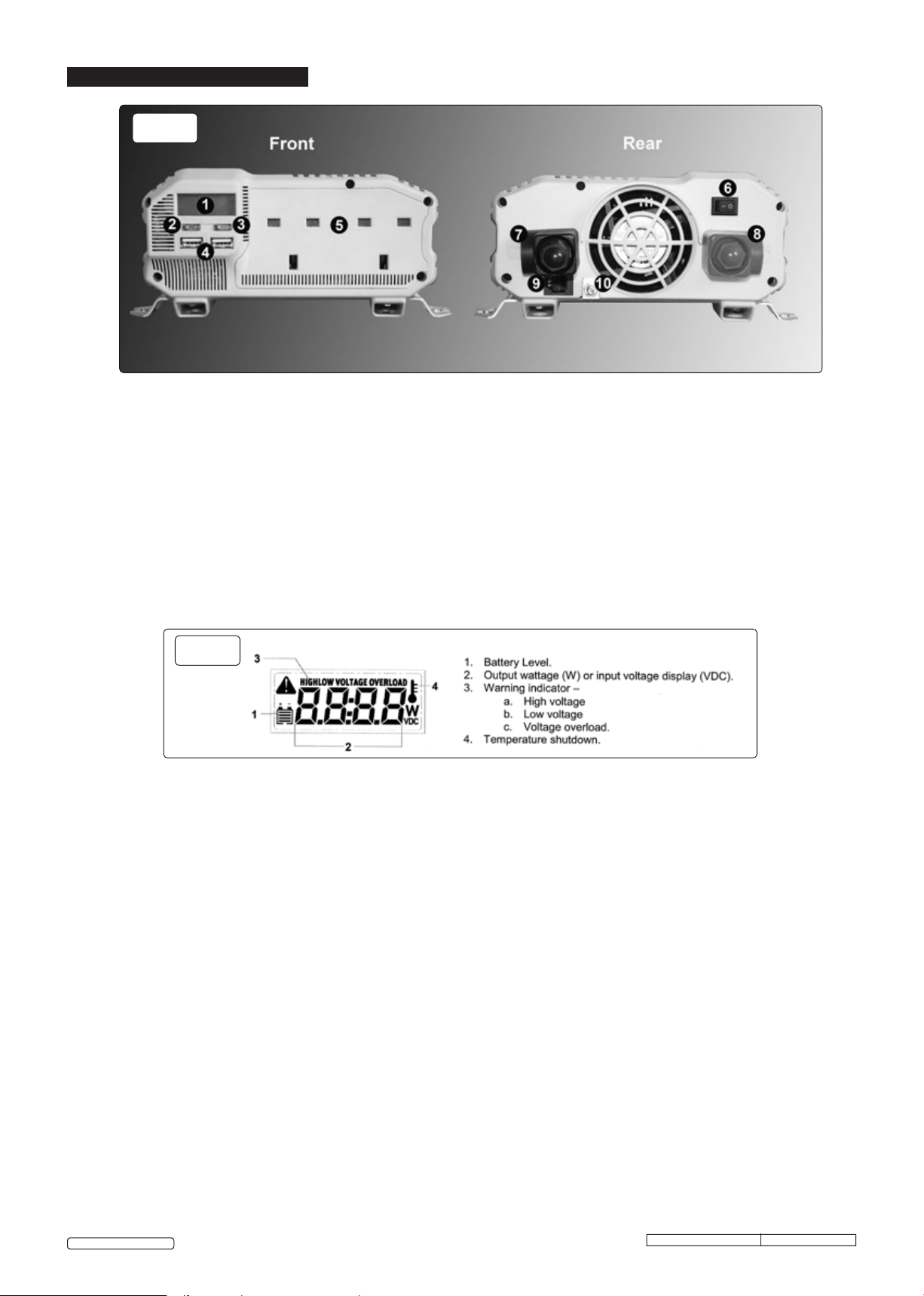
4. OPERATION
g.1
1 Digital display
2 On/off button for inverter circuits
3 Display selector button
4 USB ports
5 230V sockets
4.1. Electrical Connections.
4.1.1. Ensure that the main switch (fig.1.6) is in the off position before making any connections.
4.1.2. Remove the plastic cover, nut and spring washer from the negative (-) terminal of the inverter (fig.1.7) and place the ring connector on the
black cable over the terminal post.
4.1.3. Secure the cable with the spring washer and nut and replace the plastic cover.
4.1.4. Repeat 4.1.2. and 4.1.3. to connect the red (+) cable and fuse to the positive (+) terminal (fig.1.8)
4.1.5. If required, connect an earth cable to the earth terminal (fig.1.10). For further information, consult an automotive electrician.
6 Main on/off switch
7 Negative (-) power input terminal
8 Positive (+) power input terminal
9 Remote control socket
10 Earth terminal
4.2. Usage
4.2.1. Once connected to the battery supply, switch the main switch (fig.1.6) on.
4.2.2. Switch the inverter circuit on by means of the on/off button (fig.1.2).
4.2.3. When switched on, the digital display (fig.2) will light.
g.2
4.2.4. The main display can show input battery voltage or output amperage. Pressing the display selector button changes the display from one to
the other.
4.2.5. Before connecting an appliance to the 230V output ((fig.1.5) ensure that the appliance is switched off.
4.2.6. When connected, switch the appliance on.
4.2.7. Small appliances may be connected to the USB ports (fig.1.4).
4.2.8. If the fault alarm sounds, the fault will show on the digital display (fig.2).
4.2.9. Inductive loads, such as TV’s and stereos, require more current to operate than do resistive loads of the same wattage rating. Induction
motors, as well as some televisions, may require 2 to 6 times their wattage rating to start up. The most demanding in this category are
those that start under load, such as compressors and pumps. Testing is the only definitive way to determine whether a specific load can be
started and how long it can run. The unit will simply shut down if it is overloaded. To restart the unit after a shutdown owing to overloading,
remove the overload.
4.3. Permanent installation
4.3.1 If mounting the inverter permanently, mount in a cool, dry location close to the vehicle battery. DO NOT mount the inverter in the engine
compartment.
4.3.2. Mount the inverter horizontally, with room for air circulation around the unit.
4.3.3. Offer the unit up and mark the positions for the fixings; ensure that the fixings do not fowl any wiring, piping or reservoirs.
4.3.4. Drill on the markings and secure the unit.
4.3.5. Connect wiring as in section 4.1.
4.3.6. A remote control is supplied if the unit is to be operated in an inaccessible location. Plug one end of the USB cable into the remote control
socket (fig.1.9) and the other into the rear of the remote control switch.
4.3.7. Switch the main switch on and connect the 230V outlet to the required extension socket.
4.3.8. The remote switch will now switch the inverter on and off as required (an LED illuminates in the switch when switched on).
© Jack Sealey Limited
Original Language Version
PI1000, PI1500, PI2000 Issue: 1 - 09/11/16
Page 3

5. TROUBLESHOOTING
Problem Possible Cause
Unit will not operate 1. Poor DC contact
2. Battery voltage below 10V.
3. Load draws too much power.
4. Inverter in thermal shutdown.
5. Vehicle battery in poor condition.
6. External fuse blown due to short circuit.
7. Internal fuses blown due to short circuit.
Suggested Remedy
1. Check all DC contacts.
2. Recharge or replace battery.
3. Reduce load.
4. Allow inverter to cool.
5. Check / replace battery.
6. Check battery connections and replace fuse.
7. Contact local repair agent or Sealey technical helpline for
guidance.
Low voltage alarm
sounds continuously.
Television
Interference
1. Bad connection or wiring.
2. Low battery voltage.
1. Check and tighten all DC connections.
2. Recharge battery without load.
1. Inverter too close to the television. 1. Locate the inverter as far as possible from the TV,
antenna and other cables.
6. MAINTENANCE
6.1. The inverter contains no user-servicable parts. If a problem is encountered, contact a Sealey stockist. for advice.
6.2. To clean the casing of the inverter, first isolate from the input supply and clean with a damp, soapy cloth. DO NOT use abrasive or solvent
cleaners.
Environmental Protection
Recycle unwanted materials instead of disposing of them as waste. All tools, accessories and packaging should be sorted,
taken to a recycling centre and disposed of in a manner which is compatible with the environment.
When the product becomes completely unserviceable and requires disposal, drain off any fluids (if applicable) into
approved containers and dispose of the product and the fluids according to local regulations.
WEEE Regulations
Dispose of this product at the end of its working life in compliance with the EU Directive on Waste Electrical and
Electronic Equipment (WEEE). When the product is no longer required, it must be disposed of in an environmentally
protective way. Contact your local solid waste authority for recycling information.
NOTE: It is our policy to improve products continually and as such we reserve the right to alter data, specifications and component parts without
prior notice.
IMPORTANT: No liability is accepted for incorrect use of this product.
WARRANTY: Guarantee is 12 months from purchase date, proof of which will be required for any claim.
© Jack Sealey Limited
Sole UK Distributor, Sealey Group,
Kempson Way, Suffolk Business Park,
Bury St. Edmunds, Suffolk,
IP32 7AR
Original Language Version
01284 757500
01284 703534
PI1000, PI1500, PI2000 Issue: 1 - 09/11/16
www.sealey.co.uk
sales@sealey.co.uk
 Loading...