

Page 1

Automatic Sealers
Models: W-300A, W-305A, W-450A, W-455A, W-600A, W-605A
W-3010A, W-4510A, W-6010A, W-755AA, W-905AA, WN1205AA, WN-1505AAA, W-305AT, W-455AT
Distributed By:
Version 1.4.2
Last Updated 3/25/19
Page 2

W H A I N S T R U C T I O N M A N U AL
Copyright © 2015 by Stephanie Hwang
All rights reserved. No part of this publication may be reproduced, distributed, or transmitted in any form or by any means, including photocopying,
recording, or other electronic or mechanical methods, without the prior written permission of the publisher, except in the case of brief quotations embodied in
critical reviews and certain other noncommercial uses permitted by copyright law. For permission requests, write to the publisher, addressed “Attention:
Permissions Coordinator,” at the address below.
Sealer Sales, Inc.
8820 Baird Avenue
Northridge, Ca 91324
www.sealersales.com
Printed in the United States of America
1
Page 3

W H A I N S T R U C T I O N M A N U AL
W H A E Q U I P M E N T I N F O R M A T I O N
Model #
Serial #
Purchase Date:
Reference # (found on packing slip)
Owner:
General Information
Thank you for purchasing our W-Series Automatic Sealers
This owner’s manual contains information relating to your sealer. The manual will provide you with
basic information concerning both operation and maintenance of your new machine. Please read it
carefully as failure to do so may result in bodily injury and/or damage to the equipment.
Please fill in the information below. You will find the information on the machine identification plate.
You will need this information when ordering replacement parts or making technical inquiries.
No part of this manual may be duplicated, reproduced, stored in a retrieval system, translated, transcribed, or
transmitted in any form without the express prior written permission of Sealer Sales.
2
Page 4
W H A I N S T R U C T I O N M A N U AL
Safety Instructions
WARNING!
Below are general safety precautions and warnings that should be
understood prior to setting up or operating your equipment. Read and fully understand all instructions and
warnings prior to using this unit. Your safety is most important! Failure to comply with procedures may
result in serious injury or property damage. Remember:
responsibility.
Unsafe practices or unauthorized modifications could result in accidents or property damage. Failure to follow these
safety rules and take necessary precautions can result in serious injury as well as damage to equipment.
Never operate or service your sealer until you have read this manual completely and understand it fully.
Plug the sealer into a standard 120 Volt, 60Hz wall outlet or surge protector.
Do not use the sealer if the power cord, plug or any other parts are damaged. Be sure not to allow the
power cord to drape into your work area. Check that all parts are operating properly and perform the
intended functions. Check for any worn parts before starting operation. Check for all other conditions that
may affect the operation.
Reduce risk of unintentional starting. Make sure the power switch is in the "OFF" position before attaching
to the power source.
Always disconnect sealer from power source before servicing, changing accessories or cleaning the unit.
To provide protection against the risk of electrical shock, the power connection must be properly grounded
at all times.
Your personal safety is your
Do not leave the sealer unattended when in use. Disconnect the sealer from the power source before
leaving the work area.
Sealer is used solely for sealing thermoplastic materials. Using the machine for any other purpose can cause
damage to the machine and operator.
While operating machinery, wear close-fitting clothing and tie back long hair to prevent any external items
from getting caught in the machine. Do not wear jewelry when operating the sealer.
Never touch the heating elements with bare hand while the sealer is plugged into a power source, in
operation or just finished operation. Touching heated areas may cause fire and/or severe burns.
3
Page 5

W H A I N S T R U C T I O N M A N U A L
4
While machine is in operation, do not place fingers, tools, or other foreign objects on or into the machine.
Do not place hands or fingers near pinch points. Do not touch machine while it is operation. Perform all
procedures carefully and watch where hands and fingers are at all times.
The sealer is not water resistant or water proof. Spraying down the machine will damage machine or cause
electrical shock. Do not submerge the sealer into water or liquid.
Do not operate sealer in a corrosive or humid environment.
Always keep the machine clean, lubricated and in good working condition. Follow any maintenance and
lubrication procedures outlined in this manual. Make sure unit is disconnected from power source before
cleaning.
NEVER use any accessories or parts from other manufacturers. Machine should not be altered or modified
using parts that are not genuine authorized parts. Doing so will VOID YOUR WARRANTY.
Never leave the sealer unattended. Be safe, disconnect the sealer from power source before leaving work
area.
Always keep out of reach of children and pets.
Close supervision is necessary when any machine is near persons with reduced physical, sensory or mental
capabilities or lack of experience and knowledge . This sealer is NOT to be used by children or by persons
with reduced physical, sensory or mental capabilities or lack of experience and knowledge.
Do NOT use the sealer outdoors.
Do NOT use the sealer while under the influence of drugs, medications or alcohol.
SAVE THESE INSTRUCTIONS - REFER TO THEM OFTEN AND USE THEM TO INSTRUCT OTHERS.
Page 6

5
Basic
Principles
Place material on lower
jaw and activate
footswitch
Introduction
W-Series automatic sealers are ideal for high volume continuous poly bag and other thermoplastic sealing.
The sealer allows you to keep both hands free for quicker and more accurate sealing. Our W-Series auto
sealers can seal polyethylene, polypropylene, saran, nylon, static shielding bags, Mylar up to 30mil in total
thickness depending on the model # of the sealer.
Features of the W-Series Automatic Sealers
Your automatic sealer is equipped with a wide range of standard features and capabilities.
Simple to use - no operator training needed
Impulse sealing - no warm up time needed
Dual mode operation: auto or manual
Foot switch allows hands free operation
Die cast construction
3 separate control settings for sealing time, recycle time, and congealing time
Includes electric foot switch and adjustable work table
Equipped with either 2.7mm, 5mm, or 10mm seal widths
Option: double impulse sealing with heat on both sealing bars for sealing thicker materials
Manufacturer spare parts kit includes: 2 heating elements
How Do W-Series Automatic Sealers Work?
Our W-Series automatic impulse sealers fire a short burst of electricity through a
specially designed heating wire to weld thermoplastic materials together. The
length of the seal time will depend on the sealing characteristics of the bag being
sealed. The sealing process is simple: The operator places the bag between the
sealing jaws and presses the footswitch to activate the unit. The sealer is equipped with a digital display
for easy timer settings. The seal process ends automatically once the preset seal time is reached. The
operator retrieves the sealed bag and repeats the process. Bags are sealed repeatedly and uniformly.
Page 7
6
W-300A
W-305A
W-3010A
W-450A
W-455A
W-4510A
W-600A
W-605A
W-6010A
W-755AA
Power
110V/60Hz
Watts
450W
600W
1000W
600W
800W
TBD
800W
1300W
TBD
1200W
Seal Width
2.7mm
5mm
10mm
2.7mm
5mm
10mm
2.7mm
5mm
10mm
5mm
Sealing Length
12"
18"
24"
30"
Net Weight
40lbs
42lbs
43lbs
45lbs
45lbs
46lbs
49lbs
53lbs
54lbs
79lbs
Dimensions
17" x 14" x 8"
21" x 14" x 8"
27" x 14" x 8"
33" x 14" x 10"
Gross Weight
47lbs
48lbs
49lbs
51lbs
51lbs
53lbs
55lbs
61lbs
62lbs
82lbs
Shipping Dimensions
25" x 19" x 13"
25" x 19" x 13"
31" x 20" x 13"
38" x 21" x 4"
WN-905AA
WN-1205AA
WN-1505AAA
Power
110V/60Hz
110V/60Hz
110V/60Hz
Watts
1400W
1500A
2000W
Seal Width
5mm
5mm
5mm
Sealing Length
35"
47"
59"
Net Weight
88lbs
104lbs
123lbs
Dimensions
39" x 15" x 10"
51" x 15" x 10"
63" x 15" x 10"
Gross Weight
90lbs
106lbs
126lbs
Shipping Dimensions
45" x 21" x 14"
56" x 21" x 14"
67" x 21" x 14"
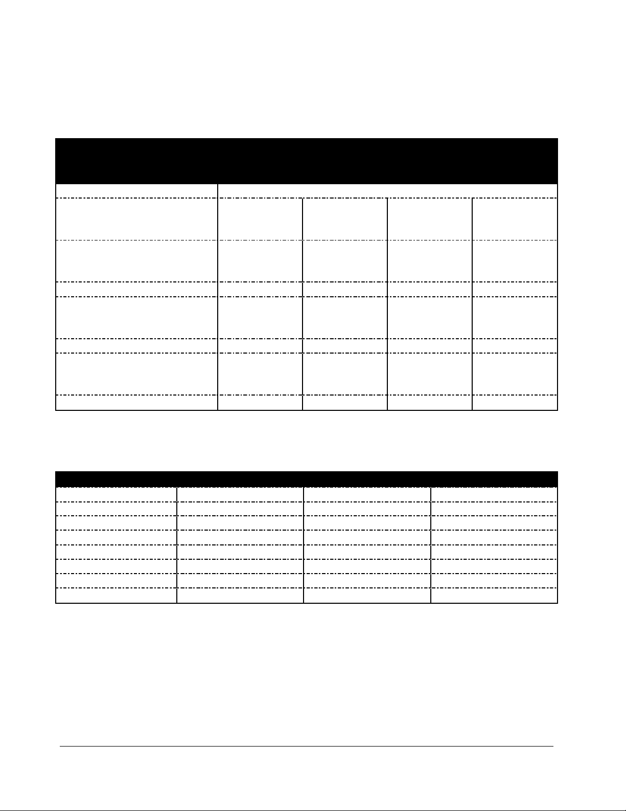
Specifications - Single Impulse Sealing
Single impulse automatic sealers are equipped with one heating element (lower sealing jaw).
Specifications - Special Order Automatic Sealers
Our special order automatic sealers are equipped with double or triple electromagnets.
Page 8

7
W-305AT
W-455AT
Power
110V/60Hz
110V/60Hz
Watts
1210W
2640W
Seal Width
5mm
5mm
Sealing Length
12"
18"
Net Weight
43lbs
49lbs
Dimensions
17" x 14" x 8"
21" x 14" x 8"
Gross Weight
50lbs
55lbs
Shipping Dimensions
25" x 19" x 13"
25" x 19" x 13"
Specifications - Double Impulse Sealing
Single impulse automatic sealers are equipped with two heating elements (upper and lower) to fuse materials
from both sides at the same time allowing thicker materials to be sealed.
Page 9

8
Power Switch
Turn off when sealer is
not in use
Manual / Auto M ode
Switc h be tween manual
(operate d by foot switch)
and automatic modes
Recycle Time Setting
Adjust time between
sealing cycl e which is
based on speed of
operato r
Sealing Time Setting
Adjust seal time based
on your bag thickness
Congealing Time Setting
Adjust congeal time based
on seal time and bag
thic kness. Congeal time is
usually 2X greater than
seal time
Foot Switch
In manual mode, press
foot switch to activate
sealing process
Sealing Jaw
Place mate rial to be
sealed on the bottom
sealing jaw
Double Impulse Sealer
Heatin g is located on
both uppe r and lower
jaws for better heat
pene tration
Getting to Know your Automatic Sealer
W-Series Foot Sealers are simple and efficient sealing machines.
Figure 1. W-Series Automatic Sealer Overview
Page 10

9
Electric Connection Diagram
Figure 2. W-Series Automatic Sealers Electric Connection Diagram
Page 11

10
Operating your Sealer
Assembly Instructions
1. Connect the footswitch to the sealer unit.
2. To install the optional working plate and table, remove screws located at the front of the unit and
install the working plate. Adjust working table height according to your bag specifications.
Operation
1. Before operating, check the heating element, PTFE cover, PTFE adhesive and the
silicone rubber.
2. Insert the power cord into the correct receptacle (110V).
3. Turn the power switch on.
4. Choose the appropriate mode: manual or auto. Press the green switch towards MAN for
manual mode and press the switch towards AUTO for automatic mode
a. For manual operation, place the material to be sealed on the lower sealing jaw and press
the foot switch to activate the upper sealing jaw.
b. For auto operation, press the switch towards AUTO to activate automatic sealing. To
turn off the automatic mode and return to manual mode, press the switch towards
MAN. Auto mode enables the upper sealing jaw to open and close automatically based
on the sealing, cooling and recycle settings.
5. Set the SEALING knob to the lowest setting. Always start with a low setting and increase
gradually as needed. Thicker bags will need a higher setting.
6. Set the CONGEALING knob setting. The cooling (congeal) setting button determines the
congealing time for the sealing. For a high quality seal, seals must be able to cool under pressure.
We usually recommend a congeal setting of at least 2x that of the seal setting, but every bag will
have variations. Thicker materials will require a longer cool (congealing) time.
7. Set the RECYCLE knob setting. Recycle time determines the amount of time the
sealing/congealing cycle will reset.. Recycle time is based on the working speed of the operator.
Tips for Successful Sealing
1. If the seal is broken or damaged, decrease the sealing time.
Page 12

11
2. If the seal is not fully welded, increase the sealing time.
3. If the sealing material sticks to the sealing pad, decrease the congealing time.
4. If the width of the seal is not perfect or does not match the size of the element, increase the
congealing time.
5. Always keep the sealer clean. Remove any residue found on the platform and PTFE cover. Silicone
spray may be used for this purpose.
6.
When replacing the heating elements, always replace the PTFE adhesive under
the heating element. A worn PTFE adhesive can cause the heating element to break.
PTFE adhesive works as a barrier between the body of the sealer and the element. Never allow the
element to come in direct contact with the sealer body as that will damage the timer.
7. Occasionally check the condition of the silicone rubber for wear or burns. A damaged silicone
rubber will affect the quality of the seal.
8. Be sure to turn off the power or unplug the unit before replacing any parts.
The
Page 13

12
W-300A
W-305A
W-3010A
W-450A
W-455A
W-4510A
W-600A
W-605A
W-6010A
W-755AA
Replacement Kit (2.7mm)
RK-12A-W-300A
RK-18A-W-450A
RK-24A-W-600A
Replacement Kit (5mm)
RK-12A5-W-305A
RK-18A5-W-455A
RK-24A5-W-605A
RK-30A5-W-755AA
Replacement Kit (10mm)
RK-12A10-W-3010A
RK-18A10-W-4510A
RK-24A10-W-6010A
Heating Element (2.7mm)
HE-12-2.7-W-300A
HE-18-2.7-W-450A
HE-24-2.7-W-600A
Heating Element (5mm)
HE-12-5-W-305A
HE-18-5-W-455A
HE-24-5-W-605A
HE-30-5-W-755AA
Heating Element (10mm)
HE-12-10-W-3010A
HE-18-10-W-4510A
HE-24-10-W-6010A
PTFE Adhesive
TA-12
TA-18
TA-24
TA-30
PTFE Cloth
TR-12-12
TR-18-12
TR-24-12
TR-30-12
Silicone Rubber (not included in RK)
SR-W-300A
SR-W-450A
SR-W-600A
SR-W-755AA
Maintenance
The following maintenance procedures should be followed to ensure the longevity of your W-Series
automatic sealer.
Inspection and Cleaning
1. Inspect your machine daily.
2. Use a clean cloth to remove any plastic residue remaining on the PTFE cloth.
3. When replacing the elements, always check the condition of the bottom PTFE tape.
4. Check the condition of the silicone rubber for wear and burns. A damaged silicone rubber will
affect the quality of the seal.
Replacement Kit Instructions
Our W-Series automatic sealers will require new heating elements and PTFE from time to time. Heating
elements will break through wear and tear. A good rule of thumb is to replace the PTFE adhesive every time
you change your heating element. The PTFE cover prevents the plastic or other thermoplastic material you
are sealing from sticking to the heating element.
Replacement kits are available from your distributor.
For single impulse automatic sealers, kits include (2) heating elements, (2) PTFE adhesives, and 1ft long roll
of PTFE cover. For replacement kit part #s, refer to your model #. **Please note that heating elements
and kits are NOT interchangeable with one another.**
Page 14

13
W-305AT
W-455AT
Replacement Kit
RK-12AD-W-305AT
RK-18AD-W-455AT
Heating Element (5mm)
HE-12-5-W-305A
HE-18-5-W-455A
PTFE Adhesive
TA-12
TA-18
PTFE Cloth
TR-12-12
TR-18-12
Silicone Rubber (not included in RK)
SR-W-300A
SR-W-450A
Figure 3. Loosen screws on PTFE plate.
Figure 4. Remove heating element cover
Figure 5. Lift up the PTFE cover to expose the heating element
Figure 6. Remove heating element cover
For double impulse automatic sealers, kits include (2) heating elements, (2) PTFE adhesives, and 2ft long roll
of PTFE cover. For replacement kit part #s, refer to your model #. **Please note that heating elements
and kits are NOT interchangeable with one another.**
To install your replacement kit on your sealer, turn off power and unplug sealer.
Removing Worn Parts.
1. Loosen the screws on the PTFE cover plate (Figure 10, Item #16).
2. Remove the heating element cover.
3. Lift up the PTFE cover to expose the heating element (Figure 10, Item #19).
4. Unscrew the nut on the mounting spring (Figure 10, Item #23-2). Remove the heating element
by lifting off the eyelets of the heating element from the mounting spring on both ends.
5. Peel off the PTFE adhesive under the heating element.
Page 15

14
Figure 7. Loosen multi-star knob to remove the PTFE roller.
Installing New Replacement Parts.
1. Remove the backing of the liner found on the PTFE adhesive.
2. Apply it to the sealer’s sealing platform. The PTFE adhesive must always extend past the sealing
platform by approximately ¼” to ½” on both ends. Bend down the excess on both ends. (The
PTFE adhesive acts a barrier between the metal body and the heating element. Never allow the
heating element to come in direct contact with the sealer’s body because it will damage the timer.)
3. Place a new element on top of the PTFE adhesive by fitting one eyelet of the heating element on
one mounting spring followed by the other mounting spring. Using a screwdriver to flex the
mounting spring inward will ease the placement of the element on the mounting spring. Check
the elements to ensure it is tight and intact.
4. Cut off any worn out PTFE cover. Ease out enough footage of PTFE cover to cover the heating
element and extend to the front of the PTFE cover plate.
5. Tighten the screws to affix the PTFE cover plate.
6. If a whole roll of PTFE cover needs to be replaced, loosen the multi-star knob (Figure 10, Item
#15) found on the plate for PTFE (Figure 10, Item #14) and remove the PTFE cover roller
(Figure 10, Item #18). Tape one end of the PTFE cover to the rod and roll up the entire piece.
Position the PTFE cover and rod using the plate for PTFE. Ease out enough footage of PTFE
cover to cover the heating element and extend to the front of the PTFE cover plate.
Page 16

15
Figure 8. Microswitch is found at the front of the body.
Figure 9. Microswitch position
microswitch
actuator
microswitch
lever
microswitch
Microwswitch Adjustment
Sometimes the microswitch (also called the trigger switch) is moved out of alignment (during shipment or
sharp movements) and needs a simple adjustment to get the unit back to proper working order.
Check for the "Click"
The microswitch activates the electrical current to heat the element. When the sealing arm meets the base of
the sealer, the microswitch will activate. User should hear the "click" of the microswitch activation. If the
"click" is intermittent, this means the microswitch is not triggered and no electrical current is passing
through.
How to Make Adjustments
1. Before operating, turn off unit and unplug.
2. Locate the microswitch which is located at the front of the body. Carefully remove the cover in
order to access the microswitch.
3. Make sure the microswitch is screwed tightly to base. If not tighten.
4. Make sure the microswitch lever touches the middle of the microswitch actuator
5. Make sure the microwswitch actuator is underneath the microswitch lever. Sometimes the
microswitch actuator moves above the microswitch lever during shipping.
Page 17

16
Parts Diagram
Figure 10. Spare Parts Diagram Overview
Page 18

17
Item Part # Description Comments
RKs
RK-Model#
REPLACEMENT KITS
Includes (2) elements, (2) PTFE adhesives, and 1ft
PTFE cover (2ft if double impulse)
specify model # when ordering
1 Bracket / Base
2
WHA-2 Control Plate / Front Panel
3
WHA-3 Rear Plate
4
WHA-4 Cover
5
WHA-5 T-Type Bracket
6 Upper Jaw specify model # when ordering
7
WHA-7 Spring, Small, Silicone Bracket (WHA, WHLF)
8 Silicone Bracket specify model # when ordering
9
SR-specifymodel# Silicone Rubber
10
WHA-10 Spring Bracket
11
WHA-11 Sucking Plate
12
WHA-12 Bushing / Pin Washer
13
WHA-13 Shaft / Hinge PIn
14
WHA-14 Plate for PTFE Sheet (Clip) (W-Series)
15
WHA-15 Multi Star Knob (W-Series)
16 PTFE Cover Plate specify model # when ordering
17
TR-specifymodel# PTFE Cover Roll specify model # when ordering
18 PTFE Cover Roller (Iron Stick) specify model # when ordering
19
HE-specifymodel# Heating Element specify model # when ordering
20
TA-specifymodel# PTFE Adhesive (Insulated Tape), 6mil specify model # when ordering
21
WHLH-49 Fiber Plate - 1.2m (47") - cut to fit
22 Aluminum Bracket specify model # when ordering
23
MS-WHA Spring Hook, Mounting
23b
HTA-WH
Heater Element Assembly
Includes Parts #23,57,58,59,60,61
HTAB-WH Heating Terminal Assembly Block
model #s W-305AT, W-3010A, W455AT, W-455AT
23c
WHLH-36 Cover for Heating Element (Screw - WHLH-61) (WHA and WHLH)
HTABwCover-WH Heating Terminal Assembly Block w/ Cover
model #s W-305AT, W-3010A, W455AT, W-455AT
24
WHA-24 Spring, Big
25 Stop Plate
26
WHA-26 Rubber Mat / Rubber Foot
27 - Gen 1.0
MSW-WHA Microswitch / Arm - Gen 1.0
27 - Gen 2.0
MSW-WHF Microswitch / Arm - Gen 2.0
27a
WHA-27A Microswitch Plates (new gen - 2013)
28
WHA-28 Power Switch (R), 4P Orange (On/Off)
29
WHA-29 Power Switch (G), 6P Green (Manual/Auto)
30
WHA-30 Knob, Red for (W-Series)
31
WHA-31 Knob (Y), Yellow
32
WHA-32 Knob (G), Green
33
WHA-33 Lamp (R), LED for E.G.O. E-00302 for (W-Series)
34
WHA-34 Lamp (Y), LED / Lamp (O)
35
WHA-35 Lamp (G), LED
36
WHA-36 Variable Resistor - 1M (W-Series)
Figure 11. Spare Parts Diagram Overview
Page 19

18
Figure 12. Spare Parts Diagram Overview
Page 20

19
Item Part # Description Comments
37
TRNS-specifymodel# Transformer specify model # when ordering
38
Solenoid-WH Solenoid (Electromagnet) TF-281 (2 for AA models)
39
WHA-39 PC Board, w/ 25A Relay
40
WHA-40 Pin for PC Board
41
FSW-WH Foot Switch
42
TISA-39 Foot Switch Connect at Sealer
42a
TISA-30c Foot Switch Connect at Foot Switch
43
WHA-43 Grommet (W-Series)
44
PC-WH Power Cord PC-WH
45
WHA-45 Fuse Holder
46
WHA-46 Fuse (1A)
47
Fuse-7amp Fuse (7A)
for W-300A
47a
Fuse-10amp Fuse (10A)
for W-305A / W-450A
47b
Fuse-15amp Fuse (15A)
for W-455A / W-600A
47c
Fuse-20amp Fuse (20A)
for W-605A
48 Nut 1/4
49 Washer 1/4 x 1 x 16
50
WHA-50 Hex Cap Screw 5/16 for #8
51
WHA-51 Washer
52
WHA-52 Hex Cap Screw 1/4x1 for #10
53 Screw 4x25
54
WHA-54 Screw #54 for Shaft/Hinge Pin (includes nut and washer)
55
WHA-55 Screw 1/4x3 1/4 for #11
56
Screw-M4x8 M4*8 Screw
57
WHA-57 Washer (R)
58
WHLH-42 Solderless Terminal 2-8 / Connecting Plate
59
WHA-59 Bushing (BK), Convex
60 Washer 3/16
61 Screw 3/16x1/2
62 Screw 5x8
63
WHA-63 Screw 5x15 - For Rubber Foot
64
WHA-64 Washer 3/8x2x24 for #5
65A
WHA-65 Spring Washer 3/8 for #5
65B Screw for Cover of Sealer (side)
66
WHA-66 Hex Cap Screw 3/8x3/4 for #5
67
WHLH-9 Handle (metal) for WHLH and WHA
70
WHDF-20 Working Plate
70a
WHDF-19A
Working Adjusting Plate Screw Set (Includes: 2-screws, 4-washers, and 2-wing nuts)
70b
WHDF-20A Working Plate Screw Set - WHA, WHDF
71
WHDF-19 Working Adjusting Plate - 6 1/4" x 9 1/2" (W x L)
Page 21

20
Problem Possible Causes Solution
No sealing or power
Sealing jaws cannot activate
1. Disconnected power cord
2. Power cord is broken
3. Blown fuse
4. On/Off switch worn out
5. Transformer worn out
1. Check or change plug
2. Replace power cord (Part#PWC-WH)
3. Replace fuse
4. Replace on/off switch (Part #WHA-28)
5. Replace the transformer (Part#TRNS-model#)
No sealing
On/Off switch light is on
Sealing light on
1. Heating element is broken
2. Poor contact at mounting spring
3. Terminals of heating element do
not make good contact
1. Replace the heating element and PTFE adhesive
under the element
2. Clean, tighten or change mounting spring
3. Clean terminals and adjust if necessary
No sealing
On/Off switch light is on
Sealing light off
1. Microswitch not activated
2. Microswitch worn out
1. Adjust microswitch lever of microswitch
position
2. Replace microswitch
No sealing
Sealing jaws remain closed
1. Solenoid worn out 1. Replace solenoid (Part#Solenoid-WH)
Auto mode is fine
Manual mode does not work
1. Footswitch worn out 1. Replace footswitch (Part#FS-WH)
Burnt PTFE cloth
1. Timer malfunction
2. Timer setting too high
1. Replace timer
2. Decrease timer setting
Broken heating element 1. Worn bottom PTFE adhesive 1. Replace bottom PTFE adhesive
Wrinkled seal
1. Seal time is set too high
2. Cooling (congeal) time is too
short
1. Decrease
2. Increase congealing time
Imperfect seal
1. Worn PTFE cloth
2. Worn silicone rubber
1. Replace PTFE cloth
2. Replace the silicone rubber
Burnt seal 1. Seal time is set too high 1. Decrease seal time
No seal 1. Seal time is set too low 1. Increase seal time
Seal sticking to PTFE adhesive
1. Worn or dirty PTFE cloth
2. Worn or dirty silicone rubber
1. Replace or clean PTFE cloth
2. Replace or clean silicone rubber
Troubleshooting
 Loading...