

Page 1

S
M
D
eLa
e
S-Serie
s
S
e
w
8
a
1
L-Bar
Sealers
odel:
istribut
S-202
d By:
MK
V
rsion 1.0
st Updated:
10/15/19
S
aler Sales |
ww.sealers
les.com | Tel: 818-718-88
8 | E-mail: contact@sealersales.com
Page 2

Page 2
SS-2028MK Sealer Service Manual
IMPORTANT - PLEASE READ THIS CAREFULLY
The development of a good safety program, that is rigidly
enforced, is absolutely imperative when involved in the operation of
industrial equipment. Our machinery is well designed and includes
extremely important safety features. The part you the user play
through proper installation and maintenance procedures is of far
greater significance than our designs. Only properly trained
individuals following rigidly enforced safety rules, as recommended
by A.N.S.I. and O.S.H.A., should be allowed to operate these
machines.
Page 3

Page 3
SS-2028MK Sealer Service Manual
TABLE OF CONTENTS
___________________________________________________________
Preface
Unpacking 5-8
Warranty Notice 9
Warranty 10-11
Warranty Exceptions 12
Warnings 13-15
Sealer Section
Description and Specifications 16
Installation and Basic Set-Up 17-23
Film Threading Diagram 24
Sequence of Operation 25-27
Compensator Adjustment 28-29
Troubleshooting 30-46
No Heat to Band Ribbon 30-35
Unbalanced Heat from Band Ribbon 36
Weak Seals/Poor Film Cut Off 37-38
Conveyor Will Not Run 39-41
Magnet Won’t Hold Down 42-44
Excessive Film Drag 45
Excessive Film Winding 46
Maintenance 47-72
Micro Knife Compensator Adjustment 47-49
Micro Knife Replacement 50-55
Tape Replacement 56
Sealing Pad Replacement 57
Seal Pad Pressure Adjustment 58
Adjust Height of Seal Bar 59
Pulse Switch Adjustment 60
Adjust Magnet Seal Pressure 61
Conveyor Motor Replacement 62-63
Replacing Seal Bars 64-67
Installation of Transite Channels 68-69
Installing Compensator 70-72
Page 4

Page 4
SS-2028MK Sealer Service Manual
Electrical Schematic 73
Electrical Panel Diagram 74
Parts Nomenclature 75
Replacement Parts List 76-79
Spare Parts List 80
Page 5

Page 5
SS-2028MK Sealer Service Manual
UNPACKING
THOROUEXCELY INSPECT EQUIPMENT UPON ARRIVAL.
If goods are received short or in a damaged condition, it
is important that you notify the carrier’s driver before he leaves
your company and insist on a notation of the loss or damage
across the face of the freight bill. Unless this is done, no claim can
be enforced against the transportation company.
If concealed loss or damage is discovered, notify
the carrier at once and insist on an inspection. This is
absolutely necessary! A concealed damage report must be
made no later than ten (5) days from the date the shipment
was delivered. Unless you do this, the carrier will not
consider any claim for loss or damage. The carrier’s agent will
then make an inspection and grant a concealed damage notation. If
you give the transportation company a clear receipt for the goods
that have been damaged or lost in transit, you do so at your own risk
and expense.
All claims must be filed within 5 days of delivery date or
carrier will not accept them.
is willing to assist in every possible manner to
collect claims for loss or damage; however, this does not hold
responsible for collection on claims or replacement of material.
UNPACKING
Page 6
Page 6
SS-2028MK Sealer Service Manual
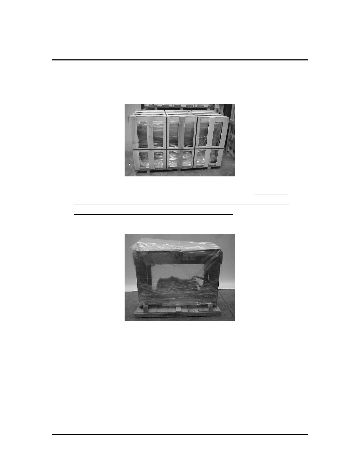
Your new L-Bar Sealer comes bolted to a pallet and
has a tri-walled corrugated box strapped to the pallet to protect it.
1. If your machine does not arrive in this condition, write on
shipping paperwork that outside of box is damaged.
Concealed damage may have occurred.
2. Remove stretch film and Poly Bag covering machine.
UNPACKING
Page 7
SS-2028MK Sealer Service Manual
Page 7
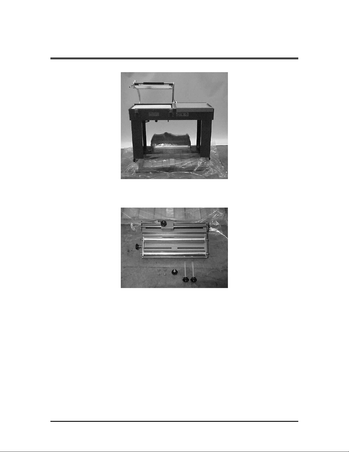
3. Remove film rack from under L-Bar Sealer.
4. Check film rack. You should have
(a) (1) Film Rack with Dual Pin Perf. Hole Punch
(b) (4) mounting bolts
(c) (1) adjustable knob
(d) (2) film roll guides
UNPACKING
Page 8
SS-2028MK Sealer Service Manual
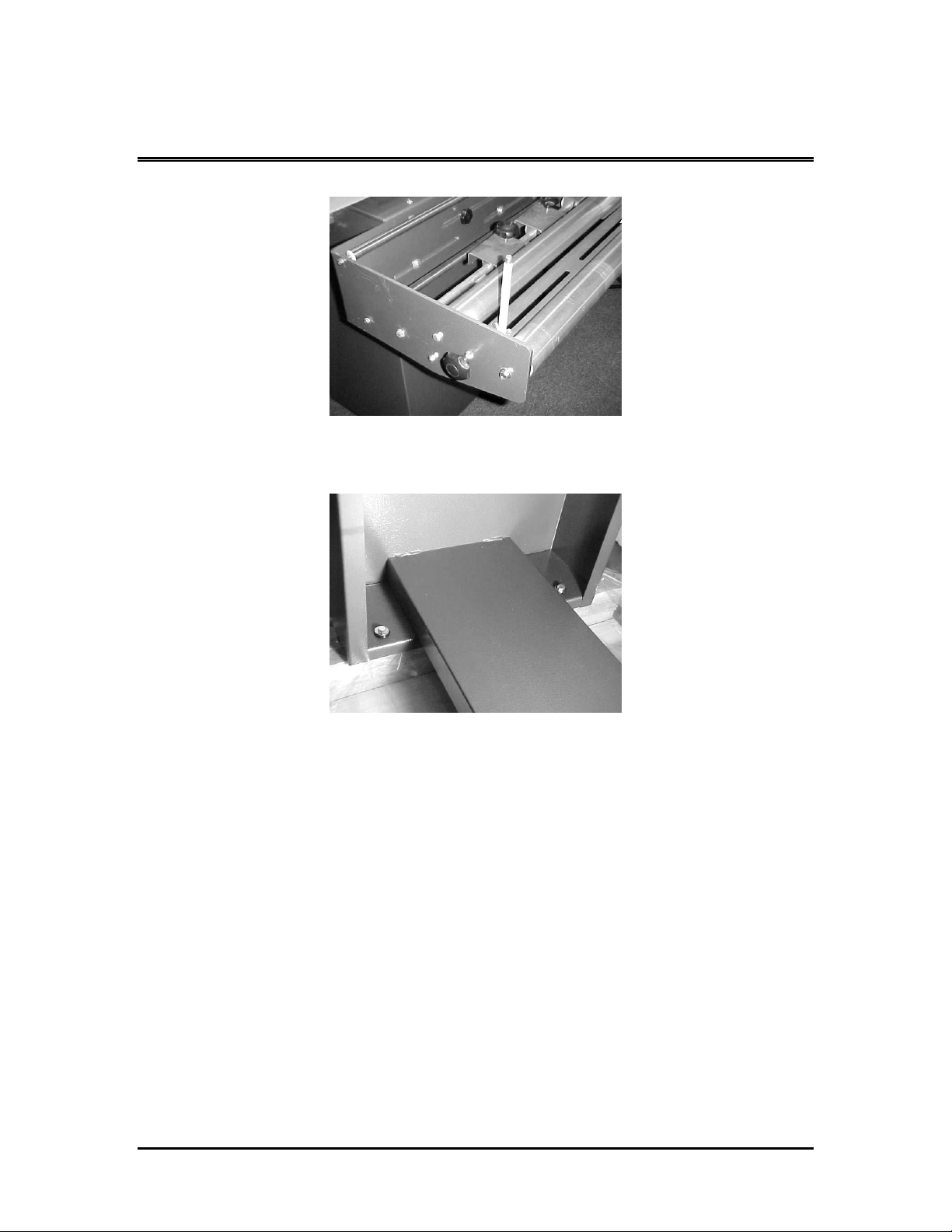
5. Mount film rack roll guides as shown.
Page 8
6. Remove bolts holding L-Bar Sealer to pallet using 13-mm
wrench.
7. Place forks of forklift under center of lower support bar of L-
Bar Sealer frame and lift off pallet.
8. Place in desired location and use locking casters to set in
place.
UNPACKING
Page 9

Page 9
SS-2028MK Sealer Service Manual
IMPORTANT WARRANTY NOTICES
OPERATING AND MAINTENANCE MANUAL
The operating and maintenance manual has been
carefully prepared to provide the user with all the information needed
to properly install, operate, and maintain your equipment.
Please read this manual carefully and refer to it
for information on the care and use of your equipment. It
is recommended that additional copies be ordered for use by
production, maintenance, and supervisory personnel. Although
the design of this equipment incorporates safeguards to protect
personnel, care should be used in operating, adjusting, and
servicing.
Attention is directed to the warranty that accompanies all
your equipment. The terms and conditions of this warranty apply
only to unmodified units. Any unauthorized modifications to
the equipment automatically voids this warranty.
WARRANTY
Page 10

Page 10
SS-2028MK Sealer Service Manual
WARRANTY
Sealer Sales, Inc. warrants each new product
manufactured to be free from defects in material and
workmanship for a period of (1) year from date of shipment by .
This warranty is not transferable with any subsequent resale.
Defective parts under warranty must be returned to Sealer
freight prepaid. Sealer Sales’s sole obligation and purchaser’s
sole remedy in the event of a warranty dispute shall be, at
Sealer Sales’s option, to repair or replace the part in question.
Labor incurred in removing or installing the defective part is
not covered by this warranty. Prior to returning any parts for
any reason, contact
Sales for a Return Authorization Number. This number must
accompany all returns.
This warranty shall not apply if equipment has been tampered
with, misused, improperly installed, altered, or has received damage
due to abuse, carelessness, accident or failure to follow
recommended regular maintenance procedures or has been serviced
by someone other than a duly authorized factory
representative without the express written consent of Sealer, Inc.
This warranty is in lieu of all other warranties, expressed or
implied, including but not limited to warranties of merchantability and
fitness for a particular purpose, non-infringement or any other
matter.
WARRANTY
Page 11

Page 11
SS-2028MK Sealer Service Manual
Sealer Sales shall have no liability to any person for direct,
indirect, incidental or consequential damages or delay resulting
from any defect negligence, or tort and customer hereby waives for
itself any and all claims for punitive damages and all claims of
negligence of strict liability or both. In no event shall our liability
exceed the purchase price of the product that was actually paid.
Sealer Sales reserves the right to make changes,
additions, or improvements to our products with no obligation
to make such changes in any previously shipped product covered by
this warranty.
Sealer Sales shall not be held liable for any damages
arising out of nor in connection with the operation of the
equipment should customer or its agent fail to maintain
equipment in safe operating condition. This warranty shall become
unenforceable if and to the extent the customer or its agents
remove, disconnect, or otherwise render useless any safety device
and or parts designed or affixed by us or fails to maintain and
service equipment in a manner as advised.
Sealer Sales provides a one-year warranty on
parts, excluding shipping or freight costs for
replacement parts. All warranty parts are shipped
F.O.B. Ontario, California. Service Labor to install part is
not covered under warranty!
WARRANTY
Page 12

Page 12
SS-2028MK Sealer Service Manual
WARRANTY EXCEPTIONS
The following parts are an exception to the
general warranty list on page 10. Each part listed below shall carry a
30-day warranty unless designated otherwise.
SS-2028MK Sealer Parts
1. Conveyor Belt
2. Fuses
The following sealer parts are considered to be consumable and
not under warranty:
1. Silicone Sponge
2. PTFE Tapes
3. Nylon Sleeves
WARRANTY EXCEPTIONS
Page 13

Page 13
SS-2028MK Sealer Service Manual
WARNINGS
Every effort has been taken to ensure your safety while
operating this machine; however, there still remain certain risks. Do
not allow this machine to be operated before informing all personnel
of the following warnings.
WARNING........
Do not tamper with the electrical wiring. Only use a
licensed electrician for maintenance. Always disconnect the electrical
power before attempting any maintenance to all electrical and/or
moving parts.
WARNING........
In order to prevent injury to personnel and/or machinery
DO NOT INCREASE SETTINGS OR RATINGS ON EITHER ELECTRICAL
OR MECHANICAL OVERLOAD SAFETY DEVICES.
WARNING........
KEEP HANDS AWAY FROM MOVING CONVEYORS AND
ASSEMBLIES. Conveyor belts that have become worn or frayed are
capable of being hazardous. They should be replaced promptly.
WARNING........
NEVER OPERATE THIS OR ANY MOVING EQUIPMENT
WITHOUT ALL COVERS AND GUARDS IN PLACE. The internal
mechanism of most packaging machinery contains numerous shear,
pinch, and inrunning nip points, many of which are capable of
causing severe injury and/or permanent disfigurement.
WARNINGS
Page 14

Page 14
SS-2028MK Sealer Service Manual
WARNING........
To minimize the potential for personnel injury, always be
sure that machine operators and others working on the machinery
are properly trained in the correct usage of the equipment and
properly instructed regarding the safety procedures for operation.
WARNING........
Heat sealing arms and sealing jaws on packaging
machinery can become very warm after a period of use. KEEP
HANDS AWAY WHILE IN OPERATION AND USE CAUTION IF THE
MACHINE HAS BEEN RUNNING RECENTLY.
WARNING........
ANY MODIFICATIONS TO EITHER THE ELECTRICAL
CIRCUITRY OR THE MECHANICAL ASSEMBLIES OF THE MACHINERY
WILL VOID ANY WARRANTIES ASSOCIATED WITH THIS
EQUIPMENT. Such modifications may introduce hazards that
would not otherwise be associated with this machinery. Sealer will
not be responsible for any consequences resulting from such
unauthorized modifications.
WARNING........
The use of certain types of plastic films in sealing and/or
shrinking equipment may result in the release of HAZARDOUS FUMES
due to the degradation of the film at high temperatures. Before
using any plastic film in this equipment, the manufacturer or supplier
of the film should be contacted for specific information concerning
the potential release of hazardous fumes. ADEQUATE VENTILATION
MUST BE PROVIDED AT ALL TIMES.
WARNINGS
Page 15

Page 15
SS-2028MK Sealer Service Manual
WARNING........
It is important that the machine operator turn off the
Main Power Switch when he/she has finished operating the unit.
WARNINGS
Page 16

Page 16
SS-2028MK Sealer Service Manual
DESCRIPTION AND SPECIFICATIONS OF
MODEL SS-2028MK SEALER
DESCRIPTION
The purpose of a SS-2028MK Sealer is for medium to
high volume packaging requiring excellent seals and minimal
maintenance. It features “micro knife technology” for sealing of
films. This model incorporates an electromagnetic hold-down
system, allowing the operator to load another package while the
preceding package is being sealed. This system provides
consistent seals. In addition, a package take-away conveyor
increases production speed by automatically discharging product
into the tunnel.
SPECIFICATIONS
Model:
Seal Area:
Machine Size:
Volts:
Amperage:
Weight:
SS-2028MK
Width: 20”
Length:
28” Length:
83” Width:
32” Height:
43” 220
20
500 lbs.
DESCRIPTION AND SPECIFICATIONS
Page 17

Page 17
SS-2028MK Sealer Service Manual
INSTALLATION AND BASIC SET-UP
IMPORTANT
Read this manual carefully, and make it available to
everyone connected with the supervision, maintenance, or production
of this machine. Additional copies are available at your request.
(Contact your distributor for this information.) Be very careful when
operating, adjusting, or servicing this equipment. If in doubt, stop
and obtain qualified help before proceeding.
INSTALLATION OF SS-2028MK SEALER
Place the L-Bar Sealer in the desired location with
the required electrical power source available. (See
power requirements.) Make certain that proper electrical wiring is
provided to guard against low voltage. If the voltage is too
low, the equipment will not function properly.
Finding the proper location is a most important function
of the initial set-up. One must take several factors into
consideration:
1. Adequate power source.
2. Relationship to source of product.
3. Relationship to L-Bar Sealer.
4. Relationship to any conveyors necessary to remove
finished product.
5. Convenience of operator.
An electrician should install a plug on the end of the main
power cord. If there is any doubt, get qualified assistance to do the
initial installation. Do not take any chances!
INSTALLATION
Page 18
Page 18
SS-2028MK Sealer Service Manual
Do not attempt to install, adjust, or operate this machine
without first reading the contents of this manual. Although the
design of the equipment incorporates safeguards to protect operating
and maintenance personnel, care should be used in operating,
adjusting, and servicing.
INSTALLING FILM RACK
IMPORTANT: Remove film rack from under sealer and
install at the end of the sealer on the right hand side with the four
bolts an center knob provided. Mounting holes are slotted for
adjustment, set film rack flush with backside of the machine frame.
INSTALLATION
Page 19
Page 19
SS-2028MK Sealer Service Manual
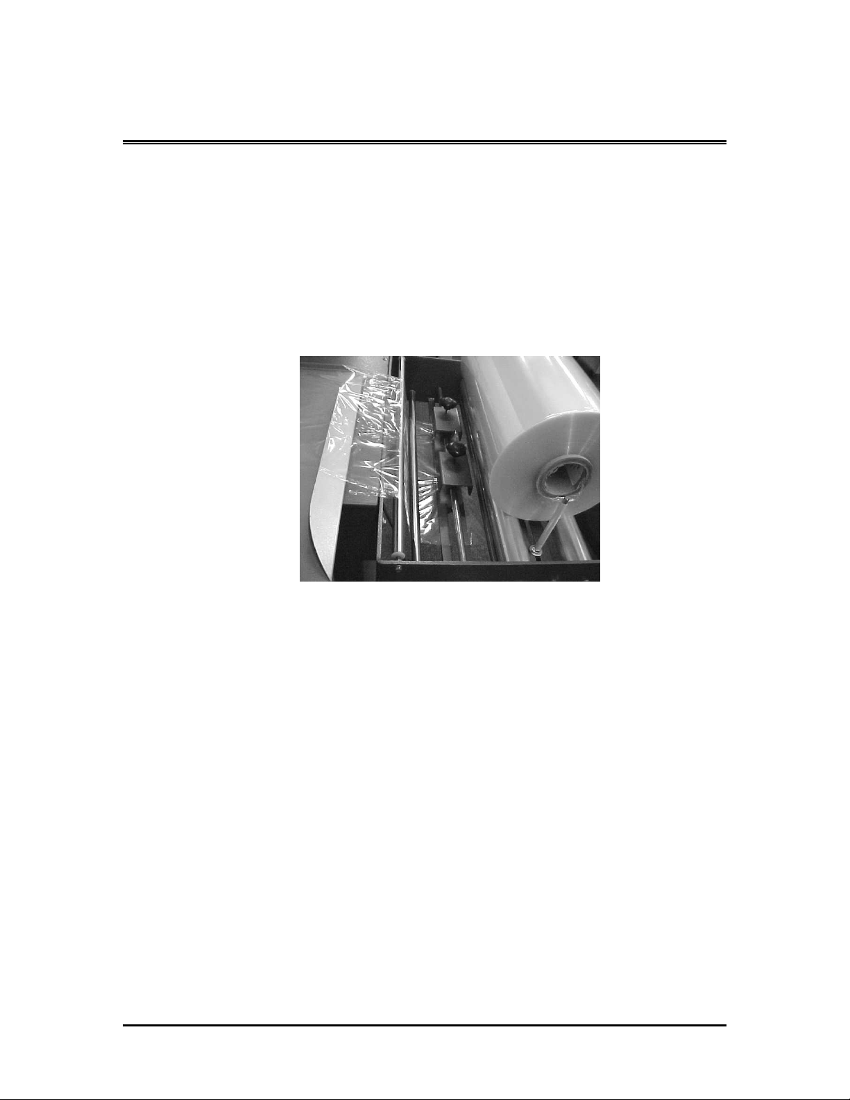
MOUNTING FILM
Select the proper width of centerfold film for the item being
packaged, allowing for width and height of package. With the
package properly positioned within the film in the sealing area, allow
sufficient film to overlap the sealing bars so that a seal may readily
be made without any possibility of open areas due to insufficient film.
Place film roll on cradle mount film rack. The centerfold is to
be placed away from the operator, toward the rear of the machine.
Position film roll on rack and tighten film guide nuts to hold film roll
in position.
Thread film through the Pin Perforator. Note that the
perforator wheel turns freely and is not binding.
INSTALLATION
Page 20
Page 20
SS-2028MK Sealer Service Manual
Once threaded, separate film top from bottom and insert
product tray between. Make sure that the centerfold of film is placed
at the rear of the product tray. This allows the operator to insert
product between the layers of film on the product tray and to
prepare to move product and film into the sealing area. When
threading film, make sure to pull more than sufficient film through
the rollers, across the product tray, and into the sealing area to
ensure sufficient film to begin operation.
Place product against rear of film separator tray. Then move
product into seal area. Be sure to leave the bag loose around the
product when making the seal. This helps eliminate the seals from
blowing out in the shrink tunnel. This completes threading and/or
mounting film.
INSTALLATION
Page 21
SS-2028MK Sealer Service Manual
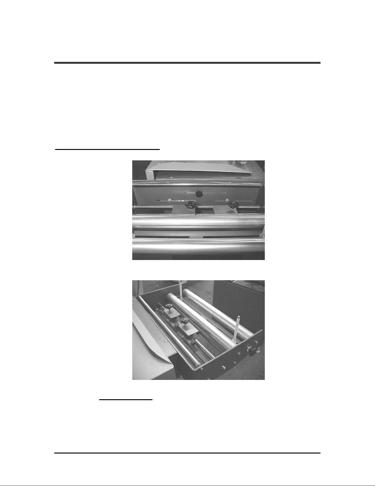
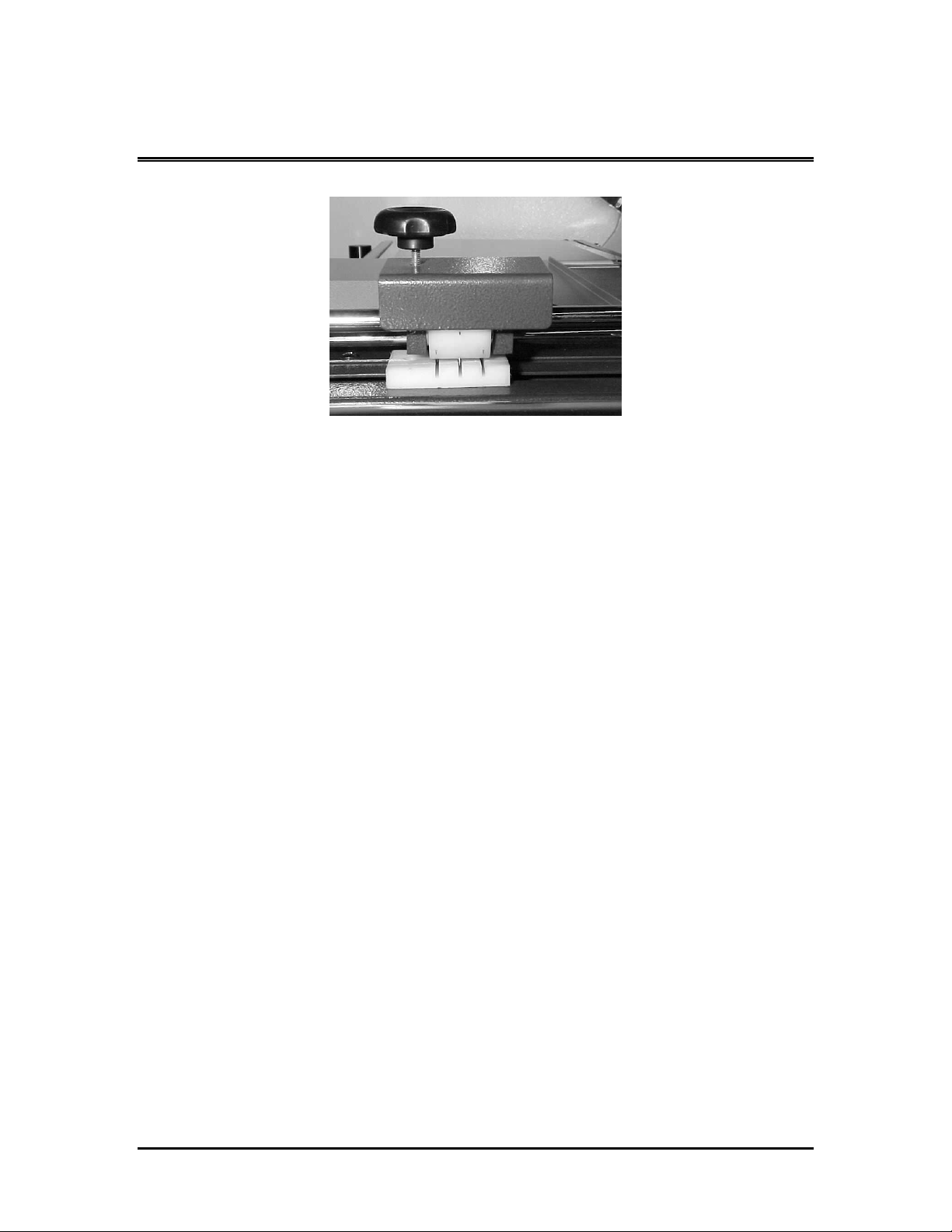
PIN PERFORATOR
Page 21
Located between the lower idler rollers, the pin perforator
creates holes for air escape as the operator pulls on the film. This
allows the air to escape as the package travels through the tunnel.
The pin perforator is adjustable and must be properly placed in
conjunction with the width of the desired package. The positioning
should always be re-evaluated when setting the machine for different
size product or different size film. Adjustments may be made with
the adjustment knob attached to the bottom of the film rack.
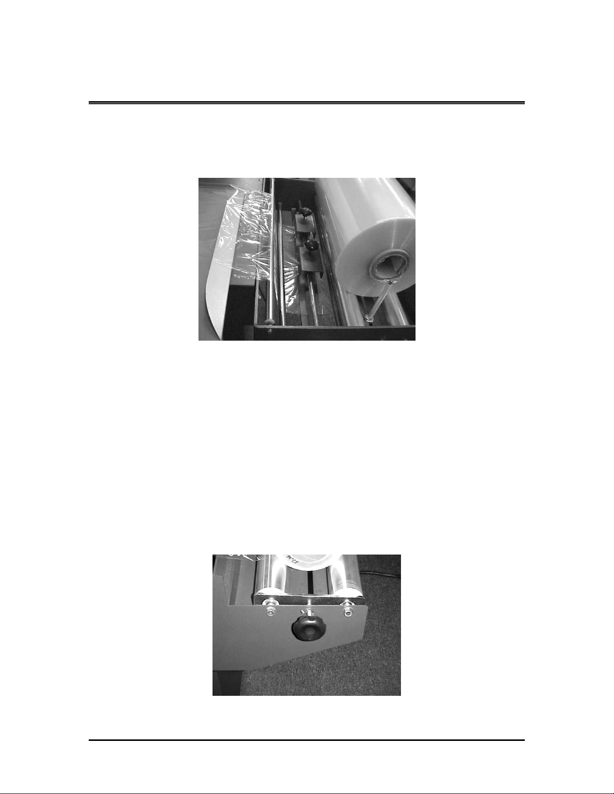
FILM BRAKE
INSTALLATION
Page 22
Page 22
SS-2028MK Sealer Service Manual
The film brake is located on the operator side of the film cradle.
It serves to create tension on the dispensing film, in order to prevent
over-run and/or slack. From time to time, the operator should reevaluate its setting to ensure proper tension.
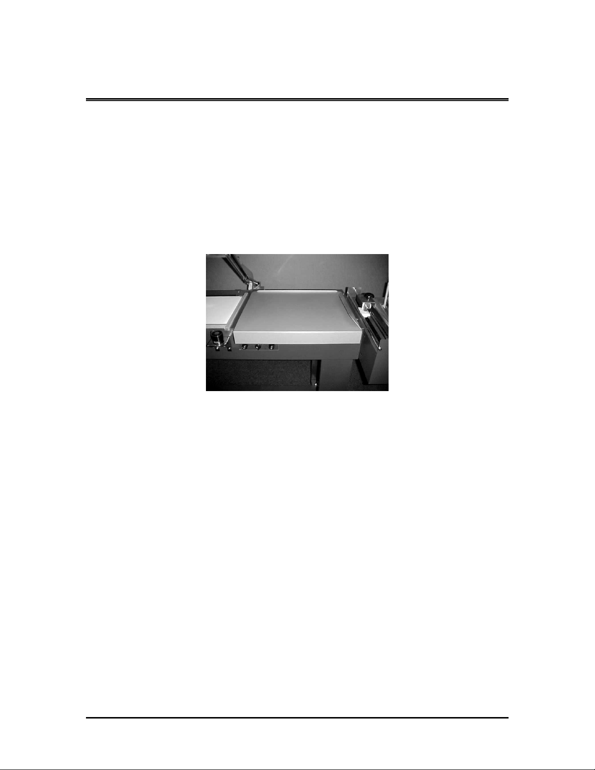
PRODUCT TRAY
The product tray is an adjustable metal platform used to
separate film and to insert product between top and bottom layers of
film.
The tray is adjustable to achieve proper depth, equal to the
depth of the package, allowing product to be placed exactly in the
centerfold of the film each time. A locking wing screw allows you to
set tray position.
INSTALLATION
Page 23
SS-2028MK Sealer Service Manual
LOCKING WING SCREW
Once the product is placed in the desired location, tighten the
wing screw under the loading tray to lock tray in position.
Page 23
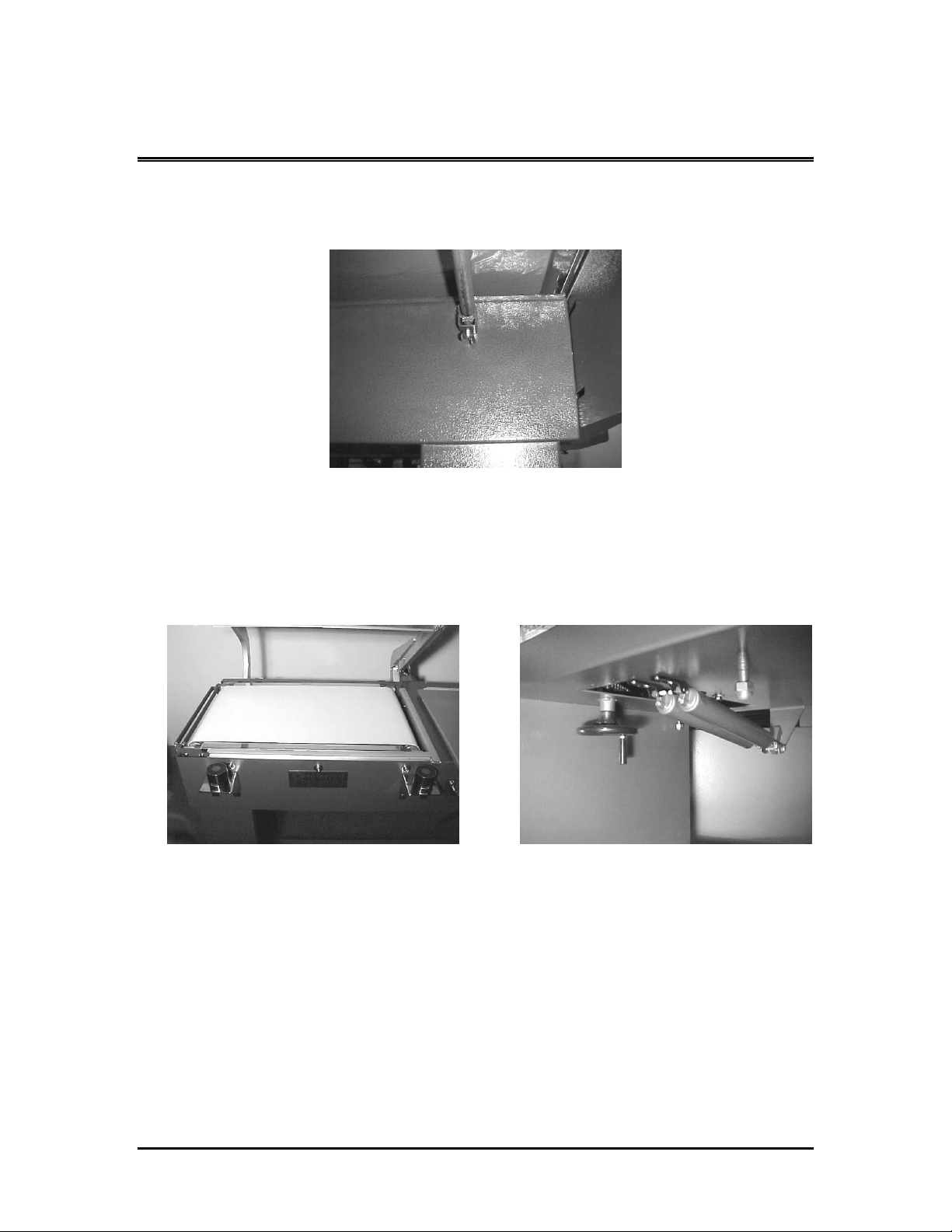
Power Discharge Conveyor
Lower Power Discharge Conveyor using the crank wheel located
underneath the Power Discharge Conveyor. The Conveyor should be
set so the package height is centered to the seal pad. In essence, ½
of the package is above the seal pad and the other ½ of the package
is below the seal pad. This will place the seal in the center of your
package and help release any film tension that may occur.
INSTALLATION
Page 24
Page 24
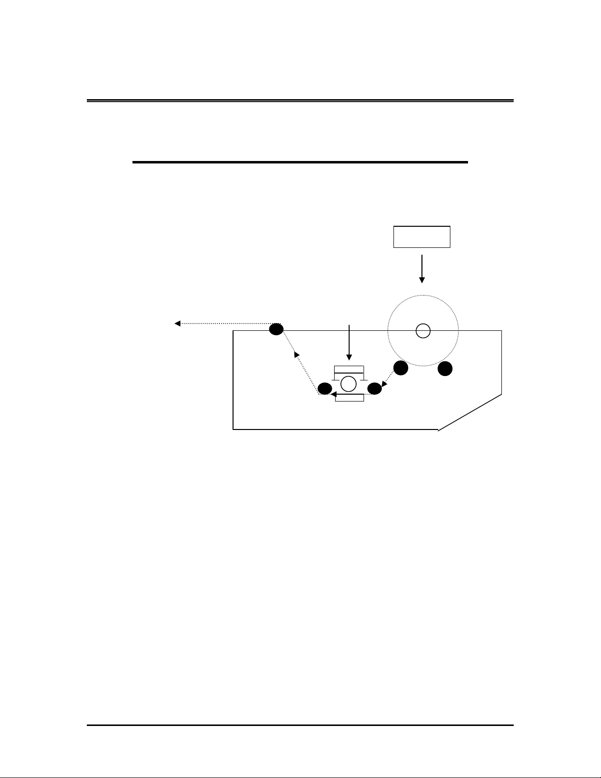
Film Roll
Pin Perf.
SS-2028MK Sealer Service Manual
FILM THREADING DIAGRAM
FILM THREADING DIAGRAM
Page 25

Page 25
SS-2028MK Sealer Service Manual
SEQUENCE OF OPERATION
A. Product is placed on the film separator tray.
B. The product tray functions as a means to separate the film,
allowing placement of product between upper and lower
portions of the film.
C. Move product into seal head area by pushing the product to the
left.
D. As the seal head is lowered toward the bottom seal pad, the
cycle switch is activated which initiates the “micro knife”,
magnet time and conveyor time. The timers are located in the
front of the machine and can be adjusted from 0 to 6 seconds.
E. Take-away Conveyor Unit - Once the seal is completed, the seal
head automatically releases and the take-away conveyor begins
to run. It is adjustable from one (1) to six (6) seconds. The
timer is located on the front of the machine.
NOTE: If too much tension is on the film while the
bag is being made, the seals will, more than
likely, be weak or will “blow out” in the seal
area while passing through the shrink tunnel.
Make sure to relax the film tension prior to
sealing.
SEQUENCE OF OPERATION
Page 26

Page 26
SS-2028MK Sealer Service Manual
SEQUENCE OF OPERATION
1. After setting the Band Ribbon compensator for the film type in
use (see page 28 for instructions), proceed as follows:
A. With film threaded, (see instructions for mounting film)
place right hand on package and slide product into the
upper left hand corner of the film (i.e. corner formed by
folded rear edge of film and previously sealed left edge of
film), pushing the package up against the ½” high
package stop at rear of product loading tray.
B. Place right hand under top sheet of film and on front
right corner of product. Place left hand on tail of both
SEQUENCE OF OPERATION
Page 27

Page 27
SS-2028MK Sealer Service Manual
sheets of film. Now push the package with right hand
and pull the film with left hand moving package and film
into lower right corner of seal area. Allow from ½” to 1”
of extra film around package. This will allow some slack
film between the package and the sealing bars, reducing
film tension.
C. Press sealing handle down. IMMEDIATELY release
pressure. The sealing head will remain down for the
duration of the time set on the seal timer.
D. The operator may then load the next package onto the
product tray, thus speeding up the sealing operation.
SEQUENCE OF OPERATION
Page 28

Page 30
Compensator
Screw
SS-2028MK Sealer Service Manual
COMPENSATOR ADJUSTMENT
Because of the importance of the adjustment of the Band
Ribbon compensator to the successful operation of the sealer, the
following explanation of its operation is given.
The front stainless steel compensator is used to adjust the
Band Ribbon temperature. As the seal head is lowered against the
bottom seal pad, a pulse switch is activated at the rear of the seal
bar supplying voltage to heat the Band Ribbon. As the Band Ribbon
heats up, the stainless steel compensator is spring-loaded and
expands as the Band Ribbon continues to heat. When the
compensator finally expands to the point that it touches the threaded
screw, the circuit is completed and the supply voltage is turned off.
The simple principle of this device is to compensate for the
residual heat that builds up in the Band Ribbon. As you operate the
L-Bar Sealer faster and faster, the actual amount of heat from the
Band Ribbon stays constant, reducing the amount of heat
transferred to the PTFE tape or seal sponge.
NOTE: The farther away you set the threaded compensator
screw from the compensator, the hotter the band ribbon will
become. A good starting point is to allow a gap of ¼”.
Thicker film such as 100GA Polyolefin might require a
slightly larger gap. You are now ready to run production on
your L-Bar Sealer.
TROUBLESHOOTING—NO HEAT TO BAND RIBBON
Page 29

Page 31
SS-2028MK Sealer Service Manual
TROUBLESHOOTING
The following guidelines are provided to aid in determining the
source of any operation difficulties that may develop. In performing
the tests and checks which follow, carefully inspect for any loose
components, broken or loose wires, poor electrical connections, etc.,
while testing the various switches, controls, relays, transformers, etc.
For checking electrical problems, use a voltage meter.
Note: While troubleshooting use caution to avoid danger of
electrical shock. When power is not required for
checking for the presence or value of voltages used,
always have it disconnected.
DISCONNECT ALL POWER BEFORE MAKING ANY REPAIRS.
REFER TO ELECTRICAL BOARD LAYOUT AND ELECTRICAL
SCHEMATIC FOR LOCATION OF ELECTRICAL COMPONENTS
NO HEAT TO BAND RIBBON
1. Check that the sealer is plugged in and that power is present at
the socket. Make sure the power switch is in the ON position.
TROUBLESHOOTING—NO HEAT TO BAND RIBBON
Page 30

SS-2028MK Sealer Service Manual
2. Make sure timer is not set on zero (0) on time dial.
Page 32
3. Check “micro knife” pulse switch adjustment.
(a) Make sure switch is being activated when the seal bar is
within ¼” of contact with seal pad.
(b) Press switch by hand. If no click is heard, replace switch.
TROUBLESHOOTING—NO HEAT TO BAND RIBBON
Page 31

SS-2028MK Sealer Service Manual
F6 – 2 AMP
F5 – 3 AMP
F4 – 2 AMP
F3 – 15 AMP
F1 – L1 --20AMP
F2 – L2 -- 20 AMP
Page 33
4. Check all fuses.
TROUBLESHOOTING—NO HEAT TO BAND RIBBON
Page 32

Page 34
GAP 1/8” to ¼ “
SS-2028MK Sealer Service Manual
5. Check “micro knife” compensator setting. You should always
have a gap of at least 1/8” to 1/4” between the compensator
and the adjustment screw. If the compensator screw is touching
the compensator the Band Ribbon will not heat up.
6. Check to see if CR1 contactor is pulled in at all times when Main
Switch is in the ON position.
TROUBLESHOOTING—NO HEAT TO BAND RIBBON
Page 33

SS-2028MK Sealer Service Manual
Wire 10
Wire 8
Wire 7
Wire 9
7. Check for operation of contactor – CR2.
(a) Check for 220 power on wires 7 and 8. When CR2 is
pulled in, you should have 220 present on wires 9 and 10.
(b) Manually engage contactor and check for continuity on
each leg. If required, clean or replace contact points or
replace contactor.
Page 35
8. Check for voltage present at both primary and secondary of
transformer T2 as per values shown in the voltage specifications.
TROUBLESHOOTING—NO HEAT TO BAND RIBBON
Page 34

Page 36
RL2
SS-2028MK Sealer Service Manual
9. Check for broken Band Ribbon inside or outside the corner block.
10. Check RL2 relay to make sure it is secure in the socket.
TROUBLESHOOTING—NO HEAT TO BAND RIBBON
Page 35

SS-2028MK Sealer Service Manual
Check Wires 14 and 26
Check Wires 12 and 13
UNBALANCED HEAT FROM FRONT
AND SIDE MICRO KNIFE BAND RIBBON
Page 37
1. Make sure Band Ribbon is seated properly in channel and you
have PTFE insulator around Band Ribbon in corner block.
2. Check for poor connections to each end of front and side
compensator assemblies and corner block.
TROUBLESHOOTING—UNBALANCED HEAT FROM BAND RIBBON
Page 36

SS-2028MK Sealer Service Manual
WEAK SEALS AND/OR POOR FILM CUT-OFF
Page 38
1. Improper setting of “micro knife” compensator. Refer to page
28 for proper adjustment.
2. Improper operating technique. Too much film tension, make
sure film is relaxed prior to sealing.
3. Check Band Ribbon to see if cleaning or replacement is
necessary.
TROUBLESHOOTING—WEAK SEALS AND/OR POOR FILM CUT-OFF
Page 37

Page 39
SS-2028MK Sealer Service Manual
4. Burned PTFE tapes 1/2” or 3/4” replace. If PTFE tapes
become burned or worn, weak seal may occur. See page 56
for Replacement Instructions.
5. Wavy silicone rubber sealing pad. Replace. (See instructions
on page 57.)
6. Seal pad pressure incorrect. (See page 58.)
7. Hold-down pressure uneven or incorrect on magnets. (See
page 61 for instructions.)
8. When seal bar is lowered, the gap between the lower magnet
and the upper magnet clamp should be 1/8”.
TROUBLESHOOTING—WEAK SEALS AND/OR POOR FILM CUT-OFF
Page 38

Page 40
F6 – 2 AMP
F5 – 3 AMP
F4 – 2 AMP
F3 – 15 AMP
Not set at zero.
SS-2028MK Sealer Service Manual
CONVEYOR – WILL NOT RUN
1. Check conveyor timer. Make sure it is not set at zero.
2. Check conveyor fuse F-6, 2 AMP, wire 18 and 19.
TROUBLESHOOTING—CONVEYOR WILL NOT RUN
Page 39

Page 41
Drive Roller Adjustment Screw
SS-2028MK Sealer Service Manual
3. Check conveyor belt and make sure it is not adjusted too
tightly. Adjust conveyor belt using Drive Roller Adjustment
Screw.
4. Check that conveyor motor sprocket set screws are not loose
on shaft.
5. Check that conveyor chain is not jammed or broken.
6. Make sure wires number 19, 20 and 7 are connected to the
conveyor motor.
TROUBLESHOOTING—CONVEYOR WILL NOT RUN
Page 40

Page 42
SS-2028MK Sealer Service Manual
7. Make sure wires number 20 and 7 are connected to C1
capacitor.
8. Make sure RL1, 220V relay is secure in relay socket and points
are not burnt.
TROUBLESHOOTING—CONVEYOR WILL NOT RUN
Page 41

SS-2028MK Sealer Service Manual
Dual Magnets
F6 – 2 AMP
F5 – 3 AMP
F4 – 2 AMP
F3 – 15 AMP
Sealing Time
Not at Zero
MAGNET WON’T HOLD DOWN
Page 43
1. Seal head will not stay down – sealer operates normally
otherwise.
2. Check seal timer (TR2) setting. Make sure it is not set at zero.
Also, check to see if burned or damaged.
3. Check magnet hold down fuse F5, 3AMP, wire 27 and 29.
TROUBLESHOOTING—MAGNET WON’T HOLD DOWN
Page 42

Page 44
Wires 27
Wires 28
SS-2028MK Sealer Service Manual
4. Check for 220 Volts (nominal) to primary of transformer (T1).
5. If voltage is present to primary winding of transformer (T1),
check for 24 (nominal) volts output from secondary of
transformer.
6. Check for 24 (nominal) volts DC output from + (positive) and –
(negative) wires number 27 and 28 on terminals of rectifier. If
no DC voltage, replace rectifier.
TROUBLESHOOTING—MAGNET WON’T HOLD DOWN
Page 43

Page 45
Wire 28
Wire 29
SS-2028MK Sealer Service Manual
7. Check for circuit continuity through windings of hold-down
magnets. Check on terminal strip wires 28 and 29.
Disconnect from terminal strip before testing.
TROUBLESHOOTING—MAGNET WON’T HOLD DOWN
Page 44

Page 46
Film brake.
SS-2028MK Sealer Service Manual
EXCESSIVE FILM DRAG
1. Check for proper film threading. (See diagram on page 23.)
2. Loosen film roll brake.
3. Make sure film guide rolls are not restraining roll from turning
freely.
TROUBLESHOOTING—EXCESSIVE FILM DRAG
Page 45

SS-2028MK Sealer Service Manual
Film brake.
EXCESSIVE FILM WINDING OR “SPILL”
Page 47
1. Tighten film roll brake.
TROUBLESHOOTING—EXCESSIVE FILM WINDING
Page 46

Page 48
SS-2028MK Sealer Service Manual
MAINTENANCE
MICRO KNIFE BAND RIBBON COMPENSATOR ADJUSTMENT
Adjustment of the Band Ribbon compensator may be required
under the following conditions:
1. During continuous use. After about 15 minutes of sealer
operation, check seal quality and, if required, reset
compensator. This may be necessary as a result of heat
buildup in the sealing head, or stretching of Band Ribbon.
2. After installing new Band Ribbon, make sure the Band
Ribbon lies properly over the entire length of the seal bar
in the channel.
3. If charring of film is noted, there is too much heat.
4. If sealing is incomplete, there is not enough heat.
To adjust the Band Ribbon compensator, refer to the
adjustment instructions on the following pages:
MAINTENANCE – BAND RIBBON COMPENSATOR ADJUSTMENT
Page 47

SS-2028MK Sealer Service Manual
All Films Except Polyethylene
Page 49
Adjust the Band Ribbon compensator (located at the left end of
the front seal bar) by loosening the wing nut and turning the
knurled-head screw until a 1/4” air gap exists. With folded film (i.e.
two layers of film) in the sealing position, bring down the sealing
head. Set the seal timer for a 1/2 to 2 setting then examine the seal.
Experimentally, in small increments, increase the Band Ribbon
compensator air gap setting until a setting is obtained which yields a
satisfactory seal and film cut off. It is important to remember that
the smallest air gap at which a satisfactory seal and film cut off is
obtained is the correct setting. If using PVC film we recommend
using a special silicone rubber for the bottom seal pad.
MAINTENANCE – BAND RIBBON COMPENSATOR ADJUSTMENT
Page 48

SS-2028MK Sealer Service Manual
Polyethylene Films
Page 50
On the Band Ribbon compensator, loosen the wing nut and
turn the knurled-head screw until a 1/4” air gap exists. Tighten the
wing nut. With folded film (e.g., two layers of film) in the sealing
position, bring down the sealing head. Set the seal timer to position
1 or 2 on the timer dial setting.
Ordinarily, it will not be possible to obtain a satisfactory seal
with the 1/4” gap setting. Experimentally, in small increments,
increase the Band Ribbon compensator air gap setting until a setting
is obtained which yields a satisfactory seal and film cut off.
Note: Any time you are using polyethylene films, we
recommend a 2” x 3 mill PTFE cloth or tape be placed
over the Band Ribbon for a better seal and for
best performance.
MAINTENANCE – BAND RIBBON COMPENSATOR ADJUSTMENT
Page 49

Page 51
SS-2028MK Sealer Service Manual
BAND RIBBON REPLACEMENT
The Band Ribbon is subject to constant wear and will
eventually require replacement as the PTFE coating eventually
wears off. To replace Band Ribbon, proceed as described below.
Replacing Micro Knife Band Ribbon
1. Loosen Allen screw on backside of compensator to loosen band
ribbon.
2. Using a 2mm Allen wrench, loosen corner screw.
MAINTENANCE-BAND RIBBON REPLACEMENT
Page 50

Page 52
Holding Screw
SS-2028MK Sealer Service Manual
3. Loosen screw holding Band Ribbon in place on front seal bar.
4. Loosen screw on back side of “side” seal bar compensator.
MAINTENANCE-BAND RIBBON REPLACEMENT
Page 51

Page 53
SS-2028MK Sealer Service Manual
Note: Once screw is loosened spring loaded compensator will
expand.
5. Remove old micro knife.
MAINTENANCE-BAND RIBBON REPLACEMENT
Page 52

SS-2028MK Sealer Service Manual
6. Take new micro knife band ribbon and bend corner
approximately 90 degrees.
Page 54
7. Cut a piece of 3 mill PTFE tape and wrap around band ribbon
before inserting into corner-block of seal bar.
8. Push band ribbon into corner block until it is fully seated at
bottom of channel. Cut off excess PTFE tape to insure good
corner seal.
MAINTENANCE-BAND RIBBON REPLACEMENT
Page 53

SS-2028MK Sealer Service Manual
9. Insert band ribbon into remaining length of channel.
Page 55
10. Push spring loaded compensator forward and tighten lock
screw.
11. Cut off excess length of band ribbon.
MAINTENANCE-BAND RIBBON REPLACEMENT
Page 54

SS-2028MK Sealer Service Manual
Page 56
Important:
After replacing Band Ribbon, be sure to adjust
the setting of the element compensator. See
page 28 for instruction.
MAINTENANCE-BAND RIBBON REPLACEMENT
Page 55

Page 57
SS-2028MK Sealer Service Manual
TAPE REPLACEMENT
The item most subject to wear on the sealer is the PTFE tape
used to cover the silicone sponge rubber on the sealing bar.
This ¾”x 10 mill tape should never be permitted to burn
through. To replace tape, proceed as follows:
1. Strip off old tape.
2. Cut off proper length of new PTFE, peel off backing, and
press new tape into position.
3. Apply ½” x 10 mill PTFE tape over the top of the ¾”
PTFE tape.
MAINTENANCE-TAPE REPLACEMENT
Page 56

SS-2028MK Sealer Service Manual
SILICONE RUBBER SEALING PAD REPLACEMENT
Occasionally it will be necessary to replace the silicone rubber
sealing pads. This should be done if the following is noted:
Gaps in the seal
Weak seals
Improper film cut-off
Excessive sealing pressure required
To replace rubber, proceed as follows:
Page 58
1. Seal pads are designed with a channel for easy
replacement. Pull silicone rubber out of the channel.
2. Replace with new silicone rubber. Press rubber back into
channel.
3. Install 3/4” - 10 mil PTFE tape on top of rubber.
4. Install 1/2” - 10 mil PTFE tape over the 3/4” tape.
MAINTENANCE-SEALING PAD REPLACEMENT
Page 57

Page 59
SS-2028MK Sealer Service Manual
Sealing Pad Pressure Adjustment for Head Return Cylinder
Uniform pressure between the band ribbon and the sealing
pads must always be maintained for proper sealing uniformity, and to
prevent element hot-spots and premature burnout. This adjustment
should be checked periodically and should always be checked when
sealing gaps occur. Proceed as follows:
1. Loosen all five bolts on lower pads just enough to
maintain a moderate sliding pressure.
2. With sealing head resting on lower pads, make sure there
are no air gaps, then tighten the five bolts on the lower
pad.
3. Adjust magnets (see page 59 for magnet adjustment).
MAINTENANCE-SEALING PAD PRESSURE ADJUSTMENT
Page 58

SS-2028MK Sealer Service Manual
Set Screws
Assembly Casting
Adjust Height of Seal Bar
Page 60
4. To raise or lower seal bar height, adjust seal head
cylinder assembly casting by loosening the three set
screws on shaft. Move assembly casting forward or
backward, then reset seal head by locking set screws.
5. Cycling head up and down, adjust set screw for proper
head speed and cushion.
MAINTENANCE –ADJUST HEIGHT OF SEAL BAR
Page 59

SS-2028MK Sealer Service Manual
Band Ribbon Pulse Switch Adjustment
Page 61
The sealing cycle should not begin until the sealing head is
within 1/4” or less of the film to be sealed. If the magnets energize
before the head is within 1/4” of the film, loosen the lock-nut and
turn the screw (located at the rear end of the side seal bar) up
slightly (counterclockwise when viewed from above). The correct
adjustment has been obtained when the magnets energize just as
the seal bar comes into contact with lower pads.
MAINTENANCE—PULSE SWITCH ADJUSTMENT
Page 60

Page 62
SS-2028MK Sealer Service Manual
Adjustment of Magnets for Correct Sealing Pressure
All magnets have been factory adjusted for equal sealing
pressure throughout the length of both the front and side seal bars.
However, if an adjustment is required, proceed as follows:
1. Disconnect the sealer’s power source.
2. Loosen the lower magnet bolts on all lower magnets so that the
magnets settle to their lowest position in the mounting slots.
3. Lower the sealer’s operating handle fully and lift lower magnets
to within 1/16” from the holders. Tighten the mounting bolts
securely to retain the proper adjustment.
MAINTENANCE—ADJUST MAGNET SEAL PRESSURE
Page 61

Page 63
Conveyor
Adjustment
Screws
Bearing Block
Bolts
SS-2028MK Sealer Service Manual
Conveyor
From time to time, it will be necessary to disassemble the
conveyor as it will need adjustments or replacement of worn parts
and general maintenance. The following information is given to
assist the operator in that general fashion. If the problem does not
rectify itself with this general explanation, discuss it with
an authorized distributor of or with directly.
A. Adjust Discharge Conveyor Belt by loosening the Bearing Block
Mounting Bolts, then adjust the Conveyor Adjustment Screw in
to loosen belt, or out to tighten belt.
MAINTENANCE-CONVEYOR MOTOR REPLACEMENT
Page 62

SS-2028MK Sealer Service Manual
Replacing Conveyor Motor
1. Disconnect power plug from source of power.
Page 64
2. Disconnect the three power wires from the rear of the motor.
3. Loosen the four bolts that hold the motor mount bracket to the
conveyor and slide motor mount forward.
4. Loosen set screws on sprocket that are attached to the motor
and remove sprocket.
5. Remove four bolts. These bolts hold the motor in place. Hold
motor while removing these bolts so the motor does not drop.
6. Follow steps 2-5 above in the opposite order to reinstall new
motor against the conveyor frame and tighten set screws.
MAINTENANCE-CONVEYOR MOTOR REPLACEMENT
Page 63

SS-2028MK Sealer Service Manual
Wire #12
Wire #14
Wire #26
Replacing Front and Side Seal Bars
1. Turn power switch to off position.
Page 65
2. Remove wire #12 from side bar compensator.
3. Remove wire #14 from front bar compensator.
4. Remove wire #26 from temperature control bracket.
MAINTENANCE-REPLACING SEAL BARS
Page 64

SS-2028MK Sealer Service Manual
Compensator Guide
Screw
5. Remove temperature control bracket.
NOTE: Bracket is held in place with two screws. Also, do not
lose the insulators.
Page 66
6. Compress front bar compensator all the way in using your
thumb and hold. Loosen Allen screw on compensator holding
Band Ribbon.
Warning: Remove compensator slowly, applying tension, as
compensator is spring loaded.
7. Remove compensator guide screw.
MAINTENANCE-REPLACING SEAL BARS
Page 65

Page 67
Allen Bolt
Remove Allen Bolts
SS-2028MK Sealer Service Manual
8. Remove Allen Bolt holding front seal bar to the outfeed bar.
9. Remove bolts holding side seal bars to casting.
10. Remove seal head from entrance casting and outfeed bar.
11. Remove the side bar compensator following steps 6 and 7.
MAINTENANCE-REPLACING SEAL BARS
Page 66

SS-2028MK Sealer Service Manual
12. Remove upper magnet holder on side bar.
Page 68
13. Remove handle.
MAINTENANCE-REPLACING SEAL BARS
Page 67

SS-2028MK Sealer Service Manual
Channel Holding Screw
INSTALLATION OF TRANSITE CHANNELS
Front and Side Seal Bar
Page 69
1. Install corner block.
2. Remove the Allen screws holding channels in seal bar.
MAINTENANCE-INSTALLING TRANSITE CHANNELS
Page 68

SS-2028MK Sealer Service Manual
Page 70
3. Remove Allen screw.
4. Remove transite channel and replace.
MAINTENANCE-INSTALLING TRANSITE CHANNELS
Page 69

Page 71
Compensator Guide
Screw
Insulated Washer
SS-2028MK Sealer Service Manual
Installation of Band Ribbon Compensators and Temperature
Control Bracket
1. Lightly grease two compensator springs and put on each seal
bar.
2. Insert compensator and compress in all the way.
3. Install compensator guide screw assemblies.
4. On the front bar, install the temperature adjustment bracket.
MAINTENANCE-INSTALLING COMPENSATOR
Page 70

Page 72
SS-2028MK Sealer Service Manual
Important: The temperature adjusting bracket must be
insulated from the casting to work properly.
5. Install new band ribbon and reset temperature adjustment
screw assembly.
6. Reconnect wires to seal head assembly.
(a) On the side seal bar, connect wire #12 to compensator
block.
(b) On the front bar, connect wire #14 to the compensator
block.
MAINTENANCE-INSTALLING COMPENSATOR
Page 71

SS-2028MK Sealer Service Manual
(c) On the temperature adjusting bracket wire #26.
Page 73
7. Install upper magnet holder on side bar.
8. Install handle and tighten set screws on each end.
9. Double check all work done before starting the
machine.
MAINTENANCE-INSTALLING COMPENSATOR
Page 72

SS-2028MK Sealer Service Manual
CR1
RL1
5
4
CR1
CR2
FUSE RATE
3
2
S1
4
2
F1
5
3
2
3
F2
L1
L2
GND
6
7
PL1
MG2
F1: 20A /250V
F2: 20A /250V
F3: 15A /250V
F4: 2A /250V
F5: 3A /250V
F6: 2A /250V
MG1
M1
+
AC
-
AC
T1
CR2
RL2
17
F6
20
C1
7
19
6
21
6
17
7
7
7
7
26
24V
25
23
24
22
29
27
F5
6
F3
10
9
26
26
25
RL2
7
7
16
TR1
18
VR1
L2
L1
C
NC
B
A
TR2
VR2
L2
L1
C
NC
B
A
31
30
32 33
RL1
RL1
MS1
RL2
F4
21
21
28
29
220V
BR1
PL1:
Power Switch
Indicator
VR1: Conveyor
Speed Potentiometer
TR1: Timer
(Discharge
Conveyor)
CR1:
Contactor
(Main Power)
S1:
Power Switch
M1: Conveyor Motor
TR2: Timer
(Sealing Time)
MS1: Pulse
Microswitch
T1: Step Down
Transformer
BR1: Rectifier
MG1,MG2:
Magnets
Compensator
VR2: Sealing Time
Potentiometer
RL1: Conveyor Relay
28
28
25
8
8 7
14
RL2:
Compensator Relay
T2: Pulse
Transformer
2614
CR2:
Contactor
(Pulse)
F1: Fuse (Main Power)
F2: Fuse (Main Power)
F6: Fuse (Conveyor Motor)
F3: Fuse (Pulse Transformer)
F4: Fuse (Step Down Transformer)
F5: Fuse (Magnets Hold Down)
C1: Capacitor
L-TYPE SEALER MODEL: 2028MK (220V)
INPUT VOLTAGE:
220V/ 60Hz, 20A
12
14
Micro Knife
T2
Page 74
ELECTRICAL DRAWING
Page 73

SS-2028MK Sealer Service Manual
BR1
CR1
TR1
T1
F3
F4
F5
F6
RL1
VR1
S1
VR2
C1
F2
F1
TS1
RL2
TR2
T2
CR2
ELECTRICAL PANEL
DIAGRAM Controls for
SS-2028MK
Page 75
ELECTRICAL PANEL DIAGRAM
Page 74

SS-2028MK Sealer Service Manual
Item
Part #
Qty
Parts List Nomenclature
S1
3400-45
Power On/off Switch
C1
3500-02
Capacitor – 3 MF 400 VAC
CR1
3400-13
Contactor Main Power
T1
1524-27
Stepdown Transformer – 220 Volt/24 Volt
M1
3400-16
Conveyor Motor
TR1
3400-76
Timer – Conveyor
CR2
3400-12
Contactor Pulse – 220 Volt
LS
3400-47
Pulse Limit Switch
BR1
1720-19
Rectifier
MAG 1 & 2
3400-76
Magnets Hold Down
TR2
3400-77
Timer – Sealing
RL1
3400-57
Conveyor Relay – 220 Volt
RL2
3400-56
Compensator Relay – 24 Volt
T2
3400-55
Pulse Transformer – 220 Volt
F1, F2, F3
3400-28
Fuse – 15 AMP 250 Volt
F5
3400-86
Fuse – 3 AMP 250 Volt
F4 & F6
3400-27
Fuse – 2 AMP 250 Volt
VR1, VR2
3400-68
Potentiometer
Page 76
MODEL SS-2028MK
SEALER
PARTS NOMENCLATURE
Page 75

SS-2028MK Sealer Service Manual
Part #
Qty
Description
3450-01
1
Arm Casting – Long
3440-20
1
Arm Casting – Short
3450-75
1
Band Ribbon
3400-96
2
Bearing – Discharge Conveyor
3440-10
4
Bearing – Discharge Conveyor Stabilizer
3450-17
1
Belt – Discharge Conveyor
3400-95
1
Bracket – Actuator
3440-01
1
Bracket – Arm Return Cylinder
3440-42
2
Bracket – Transition Roller Mounting
1524-17
1
Bridge Rectifier
3440-41
2
Bolts – Short Arm Casting Mounting
3500-02
1
Capacitor – 3 MF 400 VAC
3400-03
4
Caster
3400-04
2
Chain – Master Link
3400-05
1.5
Chain – Riveted (per ft) Conveyor Motor
3440-43
4
Chain – Riveted (per ft) Discharge Conveyor
Adjustment
3440-44
1
Compensator Adjustment Screw
3440-81
2
Compensator Block – Stainless Steel
1521-49
1
Compensator Block Insulator – Fiber Washer
3400-07
1
Compensator Shaft – Long
3440-45
1
Compensator Shaft – Short
3440-46
2
Compensator Shaft Spring
3400-09
1
Conduit (per ft)
3400-11
1
Conduit Connector – Straight – ½ “
3400-12
2
Contactor – 3 pole – 35 AMP
3400-14
1
Conveyor Adjusting Bracket
3440-66
1
Corner Block
3440-02
2
Cylinder – Head Return
3440-47
4
Discharge Conveyor – 8” Threaded Adjustment
Bolts
SS-2028MK SEALER REPLACEMENT PARTS
Page 77
REPLACEMENT PARTS
Page 76

SS-2028MK Sealer Service Manual
Part #
Qty
Description
3440-86
1
Discharge Conveyor – Nylon Take-up Block
3400-18
1
Drive Shaft
3450-20
1
Film Clamp – Front – Stainless Steel
3450-19
1
Film Clamp – Side – Stainless Steel
3400-23
4
Film Rack Bolts – 7mm x 1”
3440-48
2
Film Rack Guide Bolts
3400-25
2
Film Rack Guide Bolt Sleeve
3400-26
1
Film Rack Guide Knob
3450-24
2
Film Rack Roller – Complete
3400-22
4
Film Rack Roller Bearings – Large
3450-105
2
Film Rack Roller – Shaft
3450-21
1
Film Rack with Rollers – Complete
3440-51
1
Film Unwind Tension Adjust Knob
3440-50
1
Film Unwind Tension Plate
3400-27
1
Fuse – 2 AMP - Conveyor
3400-30
1
Fuse – 3 AMP
3400-28
2
Fuse – 20 AMP
3400-31
1
Fuse Holder
3440-03
1
Guard – Discharge Conveyor Motor
3400-32
1
Handle – Crank for Conveyor
3450-72
1
Handle – Front Seal Bar
3450-106
1
Idler Roller Assembly
3400-37
1
Knob for Conveyor Crank Handle
3440-04
1
Knob for Pin Perforator – Lower
3400-36
1
Knob for Pin Perforator – Upper
3400-35
2
Knob for Potentiometer
3400-40
2
Magnets
3400-41
2
Magnet – Upper
3400-43
2
Magnet Holder – Lower
3400-45
1
Main Power Switch
3400-46
1
Main Power Switch Plate
3440-54
1
Micro Switch Activation Bolt
3400-47
1
Micro Switch – Safety Override, Pulse, Conveyor
3400-16
1
Motor – Discharge Conveyor
Page 78
REPLACEMENT PARTS
Page 77

SS-2028MK Sealer Service Manual
Part #
Qty
Description
3400-48
2
Pillow Block Bearing
3450-49
1
Pin Perforator Assembly Complete with Shaft
3440-11
2
Pin Perforator Base – Nylon
3440-59
2
Pin Perforator Safety Cover
3450-51
1
Pin Perforator Shaft
3400-52
2
Pin Perforator Wheel – 5/8” I.D.
3450-54
1
Product Separator Tray
3400-56
1
Relay – Compensator – 24 Volt
3400-57
1
Relay – Conveyor – 220 Volt
3400-58
2
Relay Base
3450-74
1
Roller – Discharge Belt – Drive and Idler
3450-73
2
Rollers – Transition
3440-06
2
Screw – Guide with Insulator
3440-62
1
Screw – Wing (Product Loading Tray)
3450-60
1
Seal Bar – Lower – Front (Bottom Pad)
3450-61
1
Seal Bar – Lower – Side (Bottom Pad)
3450-85
1
Seal Bar – Upper Front – Complete
3450-86
1
Seal Bar – Upper Side – Complete
3450-30
1
Seal Pad Sponge Rubber – Front
3450-25
1
Seal Pad Sponge Rubber – Side
3450-33
1
Shaft – Seal Head
3440-07
4
Shoulder Bolt – Film Clamps
3440-67
2
Spacer Film Clamp
3400-68
2
Speed Potentiometer (Vr1 & Vr2)
3440-22
1
Sponge – Handle
3440-08
4
Spring – Film Clamp
3450-69
1
Sprocket – Conveyor Drive Shaft
3450-71
1
Sprocket – Conveyor Motor
3400-72
4
Sprocket – Conveyor Up/Down
100002
1
100003
1
3400-73
1
Temperature Adjusting Bracket
1521-09
1
Temperature Adjustment Screw Assembly
3400-74
1
Terminal Strip – 12 Lug
Page 79
PTFE Tape – ½” x 10 mill
PTFE Tape – ½” x 10 mill
REPLACEMENT PARTS
Page 78

SS-2028MK Sealer Service Manual
Part #
Qty
Description
3400-76
1
Timer – Conveyor
3400-77
1
Timer – Seal
3400-55
1
Transformer – Pulse 220 V
1524-27
1
Transformer – Stepdown 220 V to 24 V
3450-90
1
Transite Channel – Front
3450-91
1
Transite Channel - Side
3440-09
4
Washer Stainless Steel – Film Clamp
Page 80
REPLACEMENT PARTS
Page 79

SS-2028MK Sealer Service Manual
Item
#
Part #
Description
Qty.
Price
1
3450-75
Band Ribbon
1
2
3440-66
Corner Block
1
3
3400-27
Fuse – 2 AMP
2
4
3400-30
Fuse – 3 AMP
2
5
3400-28
Fuse – 15 AMP
2
6
3450-15/20
Seal Pad Rubber – Front and Side
1/set
8
1350-08
1 RL
9
1350-14
1 RL
10
3450-90/91
Transite Channel – Set
1
11
3400-47
Impulse switch
1
12
3400-76
Timer board
1
13
3400-12
Contactor
1
Total Cost
$Call
Spare Parts
List SS-2028MK
Page 81
½” x 10 mill x 10 yrd. PTFE
Tape
¾” x 10 mill x 10 yrd. PTFE
Tape
9/17/15
Replacement Parts
 Loading...