

Page 1

Technical Manual
Edition: V1.00/2014
Page 2

GTS Technical Manual
Index
1Forward
1.1 Target 1
1.2 Technical Training 1
1.3 Technical Manual 1
1.4 Summary 2
2Elementary
2.1 Health & Safety 1
2.2 ESD 1
3 General
3.1 General information 1
3.1.1 Part reference 1
3.1.2 Consumable supplies 1
3.1.3 Direction description 1
3.1.4 Power source 1
3.2 Required material 2
3.2.1 Tools 2
3.2.2 Material 2
4Technical data
4.1 Machine range 1
4.2 Technical information 2
4.2.1 Machine profile 2
4.2.2 Technical data 2
4.2.3 Machine speed 3
technical manual XP_M_R_V1.00IVZ.fm
4.2.4 Dimensions and weights 3
4.2.5 Battery 4
4.2.5.1 Battery compartment 4
4.2.5.2 Battery specifications 5
4.2.6 Charger 6
4.2.7 Brush system 6
4.2.8 Suction power 7
4.2.9 Additional 7
4.3 Accessories & Additional parts 7
4.3.1 Accessories 7
4.3.2 Additional parts 8
5 Mechanical
5.1 Control group 1
5.1.1 Removing of cover 1
5.1.2 Mounting of cover 2
5.1.3 Removing of Electronics hall sensor set 3
5.1.4 Mounting of Electronics hall sensor set 4
5.1.5 Removing of driving speed lever 5
5.1.6 Mounting of driving speed lever 6
5.2 Upper part 7
5.2.1 Removing of vacuum motor 7
28. November 2014 Edition: V1.00/2014 1-1
Copyright © 2014, Diversey Care
Page 3

GTS Technical Manual
5.2.2 Mounting of vacuum motor 8
5.2.3 Removing of tank cover 9
5.2.4 Mounting of tank cover 11
5.2.5 Removing of hose 13
5.2.6 Mounting of hose 14
5.3 Tank 15
5.3.1 Removing of waste water sensor 15
5.3.2 Mounting of waste water sensor 16
5.3.3 Removing of tank set 17
5.3.4 Mounting of tank set 18
5.4 Base 19
5.4.1 Removing of castor wheel 19
5.4.2 Mounting of castor wheel 20
5.4.3 Removing of drive gear 21
5.4.4 Mounting of drive gear 22
5.4.5 Removing of step board 23
5.4.6 Mounting of step board 24
5.5 Fresh water circle 25
5.5.1 Removing of pumps 25
5.5.2 Mounting of pumps 26
5.5.3 Removing of magnetic valve 27
5.5.4 Mounting of magnetic valve 28
5.6 Squeegee lowering mechanism 29
5.6.1 Removing of squeegee linear drive 29
5.6.2 Mounting of squeegee linear drive 30
5.6.3 Removing of swinging arm 31
5.6.4 Mounting of swinging arm 33
5.7 Squeegee 1650/XP/XP-M/XP-R 35
5.7.1 Removing of wire spring 35
5.7.2 Mounting of wire spring 36
5.7.3 Removing of front and back blades 38
5.7.4 Mounting of front and back blades 39
5.8 Tool lowering unit 40
5.8.1 Removing of spring bracket set configured 40
technical manual XP_M_R_V1.00IVZ.fm
5.8.2 Mounting of spring bracket set configured 42
5.8.3 Removing of brush unit linear drive XP-M 43
5.8.4 Mounting of brush unit linear drive XP-M 44
5.8.5 Removing of brush unit linear drive XP-R 45
5.8.6 Mounting of brush unit linear drive XP-R 46
5.8.7 Removing of tool lowering unit XP-R 47
5.8.8 Mounting of tool lowering unit XP-R 49
5.9 Brush drive 50
5.9.1 Removing of complete brush unit XP-M 50
5.9.2 Mounting of complete brush unit XP-M 52
5.9.3 Removing of complete brush unit XP-R 54
5.9.4 Mounting of complete brush unit XP-R 56
5.9.5 Removing of support with bearing (synchronisation) XP-M 58
5.9.6 Mounting of support with bearing (synchronisation) XP-M 59
5.9.7 Removing of brush belt & brush motor XP-M 60
5.9.8 Mounting of brush belt & brush motor XP-M 61
5.9.9 Removing of eccentric shaft XP-M 62
5.9.10 Mounting of eccentric shaft XP-M 63
5.9.11 Removing of brush belt XP-R 64
5.9.12 Mounting of brush belt XP-R 66
5.9.13 Removing of brush pulley XP-R 68
5.9.14 Mounting of brush pulley XP-R 69
5.9.15 Removing of motor & motor belt XP-R 71
5.9.16 Mounting of motor & motor belt XP-R 72
28. November 2014 Edition: V1.00/2014 1-2
Copyright © 2014, Diversey Care
Page 4

GTS Technical Manual
5.9.17 Removing of intermediate pulley XP-R 73
5.9.18 Mounting of intermediate pulley XP-R 74
6 Electrical
6.1 System architecture 1
6.1.1 General 1
6.2 Dashboard 2
6.2.1 Removing of dashboard 2
6.2.2 Mounting of dashboard 3
6.2.3 Main functions 4
6.2.4 Dashboard connections 4
6.3 Dashboard service menu 7
6.3.1 Reset service hour counter 7
6.4 Power electronics 10
6.4.1 Removing of power electronics 10
6.4.2 Mounting of power electronics 11
6.4.3 Main functions 12
6.4.4 Power electronics connections 12
6.5 Charger 16
6.5.1 Removing of charger 16
6.5.2 Mounting of charger 17
6.5.3 Charger connections 18
6.6 Power relay 20
6.6.1 Removing of power relay 20
6.6.2 Mounting of power relay 21
6.7 Hall sensors 22
6.7.1 Description 22
6.7.2 Guidance 22
6.7.3 Throttle 23
6.7.4 Brush pressure 23
6.8 Safety concept 24
6.8.1 Concept 24
6.8.2 Electromechanical disconnection (Relay 04/137) 24
technical manual XP_M_R_V1.00IVZ.fm
6.8.3 Emergency loop 25
6.8.4 SAFETY_OK signal loop 26
6.8.5 Emergency brake 27
6.8.6 Charging batteries with low voltage 27
6.8.7 Internal-/external charger 27
6.9 Schematics 29
6.9.1 Electrical schematics XP-M 29
6.9.2 Electrical schematics XP-R 30
6.10 Battery 31
6.10.1 Battery connection 6V 31
7 Additional information
7.1 Available GTS Newsletter/Instructions 1
8Revision
9Appendix
10 Notes
28. November 2014 Edition: V1.00/2014 1-3
Copyright © 2014, Diversey Care
Page 5

Technical Manual
1 Forward
28. November 2014 Edition: V1.00/2014
Copyright © 2014, Diversey Care
Page 6

GTS Technical Manual
1 Foreword
1.1 Target
To serve our customers faster and more efficient it is important to achieve a general
standard of technical know how with our partners in the market.
Therefore we developed a Technical Training concept which is based on e-spares. The
concept consists of a Technical Manual and a Technical Training.
These two tools will be produced for each newly launched machine with a certain complexity. The Technical Manual will be available as PDF file and can be downloaded from
e-spares. The Technical Training documentation will be distributed after having attended the technical training.
1.2 Technical Training
The Technical Training is addressed as reference book for the technical training sessions
and will be distributed to the floor care responsible and/or to the technical training re-
01.0 TASKI - foreword_V1.00.fm
sponsible after attending a training session provided by GTS (max. 2 persons per country).
The intension is, that after this session, a technical trainer is able to perform technical
training for their local technical staff and in this way to transfer the knowledge to all service technicians.
The Technical Training is not intended as manual for the service technicians and will be
distributed only to the training responsible of each country.
1.3 Technical Manual
The Technical Manual is addressed to the service technicians and should be translated
and distributed after a technical training.
It contains a summary of procedures, hints and suggestions etc. which are helpful and
28. November 2014 Edition: V1.00/2014 1-1
Copyright © 2014, Diversey Care
Page 7

GTS Technical Manual
essential for the daily business. The Technical Manual can be downloaded from espares/documents.
1.4 Summary
We are convinced that the Technical Manual concept together with the Technical Training
are powerful tools, which will help our service organisations to achieve a higher level of
quality in repairs and customer satisfaction.
If you have any comments or questions do not hesitate to contact your country responsible.
Sincerely yours
GTS Team
01.0 TASKI - foreword_V1.00.fm
28. November 2014 Edition: V1.00/2014 1-2
Copyright © 2014, Diversey Care
Page 8

Technical Manual
2 Elementary
28. November 2014 Edition: V1.00/2014
Copyright © 2014, Diversey Care
Page 9

GTS Technical Manual
2Elementary
2.1 Health & Safety
Scrubber dryers may be powered by mains electricity or batteries. There are risks associated with both, which call for proper precautions, such as the provision of good ventilation and the elimination of risk of ignition.
All work, carried out on such machines, should only be performed by trained personnel
in accordance with local regulations.
Before working on such a machine, isolate it from any electrical power source.
Always wear the required personal protective equipment (including gloves and goggles)
that must be worn when potentially exposed to any hazardous material and when carrying out hazardous tasks.
Note that parts may be contaminated with chemical product. If possible flush hoses out
with fresh water prior to carrying out any maintenance. For information on chemical
products that are used in this machine, please carefully read the product label and Ma-
02.1 TASKI - elementary_V1.00.fm
terial Safety Data Sheet (MSDS).
Empty water tanks prior to carrying out any maintenance. Ensure contaminated water is
emptied into an approved drain. Avoid pollution.
2.2 ESD
Static electricity is electricity at rest or the accumulation of electric charge, as opposed
to an electric current which is the movement of electricity. The flow or movement of people and/or materials in and through the environment causes separation of electrons and
therefore static electricity. A familiar example of static electricity is when a person walks
across a carpeted floor. Static electricity/electrostatic charge is generated simply by the
contact and separation of the soles of that individual's shoes from the carpeted floor.
Electrostatic Discharge (ESD) occurs when the electrostatic charge is transferred from a
material that carries the charge to an electrostatic sensitive device. In the example above,
this electrostatic discharge is the „shock“ felt after walking across the carpeted floor and
then touching a door knob. It is this electrostatic discharge, which comes in varying de-
28. November 2014 Edition: V1.00/2014 2-1
Copyright © 2014, Diversey Care
Page 10

GTS Technical Manual
grees, that can be most damaging to electronical devices.
Static electricity, is a natural phenomenon and consequently electrostatic discharge is
the primary cause of countless problems affecting industry, business and personal life.
These problems can be as simple as the shock resulting from walking across a carpet; as
costly as the destruction of sensitive electronic components.
Almost any material can generate static electricity. The ability to store or unload the
charge depends on the type of material.
Static discharge can damage devices, this can result in immediate product failure or in a
latent failure. Latent failures can go undetected for a period of time, the results are product failure in the field.
Electrostatic fields are associated with charged objects.
The degree of severity of ESD events depends on the type of discharge which occurs. The
three most common ESD charge transfers are:
• from an external object to the device.
• from a device to another object.
• resulting from electrostatic fields.
02.1 TASKI - elementary_V1.00.fm
Please do not store electronics without ESD bags at any time.
28. November 2014 Edition: V1.00/2014 2-2
Copyright © 2014, Diversey Care
Page 11

Technical Manual
3 General
28. November 2014 Edition: V1.00/2014
Copyright © 2014, Diversey Care
Page 12

GTS Technical Manual
3 General
3.1 General information
3.1.1 Part reference
Explicitly mentioned parts are defined by references corresponding to
the e-spares spare parts list.
E.g. Tank axle (02/118) corresponds to the parts list on e-spares, sub
assembly 2, position 118.
3.1.2 Consumable supplies
If you have to remove cable ties then position the new ones at the
original place.
If you have to remove self locking nuts, you should replace them by
new ones.
03.1 TASKI - general_V1.00.fm
3.1.3 Direction description
On the „RH“ always means on the right hand side of the machine in
working direction (when you are standing behind the machine).
On the „LH“ always means on the left hand side of the machine in
working direction (when you are standing behind the machine).
3.1.4 Power source
Depending on the work it might be required to remove the power
source (mains/batteries) from the machine.
The in here mentioned sequences (mechanical and electrical) are
based on the assumption that the power source (mains/batteries)
were removed from the machine before.
28. November 2014 Edition: V1.00/2014 3-1
Copyright © 2014, Diversey Care
Page 13

GTS Technical Manual
3.2 Required material
3.2.1 Tools
• A standard range of tools is required e.g.
• Fork spanners.
• Allen keys.
• Torx keys.
3.2.2 Material
• No special tools are required.
03.1 TASKI - general_V1.00.fm
The above listings are only a recommendation for the technical
training.
28. November 2014 Edition: V1.00/2014 3-2
Copyright © 2014, Diversey Care
Page 14

Technical Manual
4 Technical data
28. November 2014 Edition: V1.00/2014
Copyright © 2014, Diversey Care
Page 15

GTS Technical Manual
4Technical data
4.1 Machine range
SKU Description Version Series
7522819 TASKI swingo XP-M 01
7523098 TASKI swingo XP-M Seafreight 01
7523359 TASKI swingo XP-M BMS EURO 01
7523361 TASKI swingo XP-M BMS SEV 01
7522818 TASKI swingo XP-R 01
7523097 TASKI swingo XP-R Seafreight 01
7523356 TASKI swingo XP-R BMS EURO 01
7523358 TASKI swingo XP-R BMS SEV 01
Table 1: Machine range
Remarks
SKU‘s for all TASKI swingo XP types are the „naked machine“. Cleaning tools and batteries
have to be ordered separately.
04.1 swingo XP_M_R - technical data_V1.00.fm
28. November 2014 Edition: V1.00/2014 4-1
Copyright © 2014, Diversey Care
Page 16
GTS Technical Manual
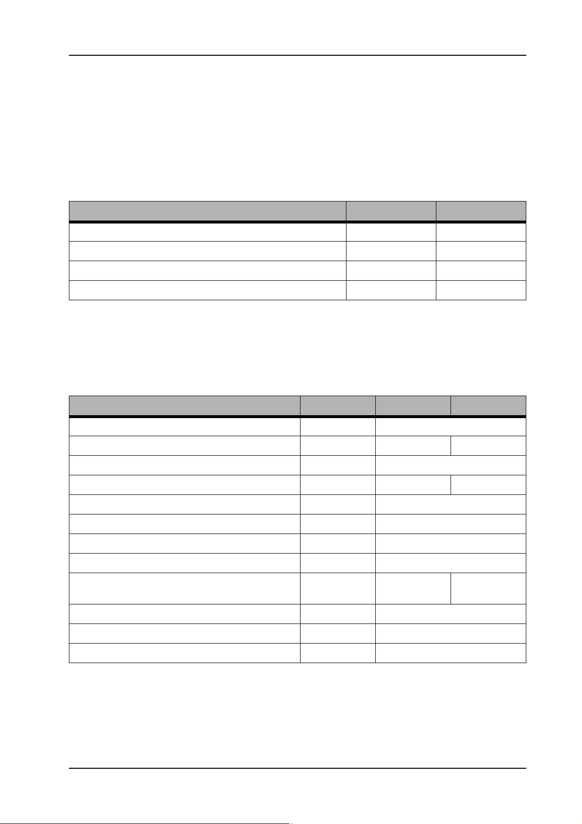
4.2 Technical information
4.2.1 Machine profile
Pos. Unit Value
Theoretical performance (m²/h) 4500
Working width (mm) 750
Squeegee width (mm) 950
Tank size (bag system) (l) 113
Table 2: Machine profile
4.2.2 Technical data
Pos. Unit Value XP-R Value XP-M
Noise level (dB(A)) 69
Vibration (m/s2) < 0.5 < 2.5
Approvals ÖVE
Nominal consumption (W) 1275 1200
04.1 swingo XP_M_R - technical data_V1.00.fm
Power drive motor (W) 2x 450 (900)
Power suction motor (W) 490
Voltage (V) 24
Battery capacity maintenance-free (Ah)/C5 180
Battery autonomy max.
(180 Ah maintenance free battery)
Internal charger only BMS models
Protection grade IPX3
(h) 3.25 3.5
Protection II
Table 3: Technical data
28. November 2014 Edition: V1.00/2014 4-2
Copyright © 2014, Diversey Care
Page 17
GTS Technical Manual
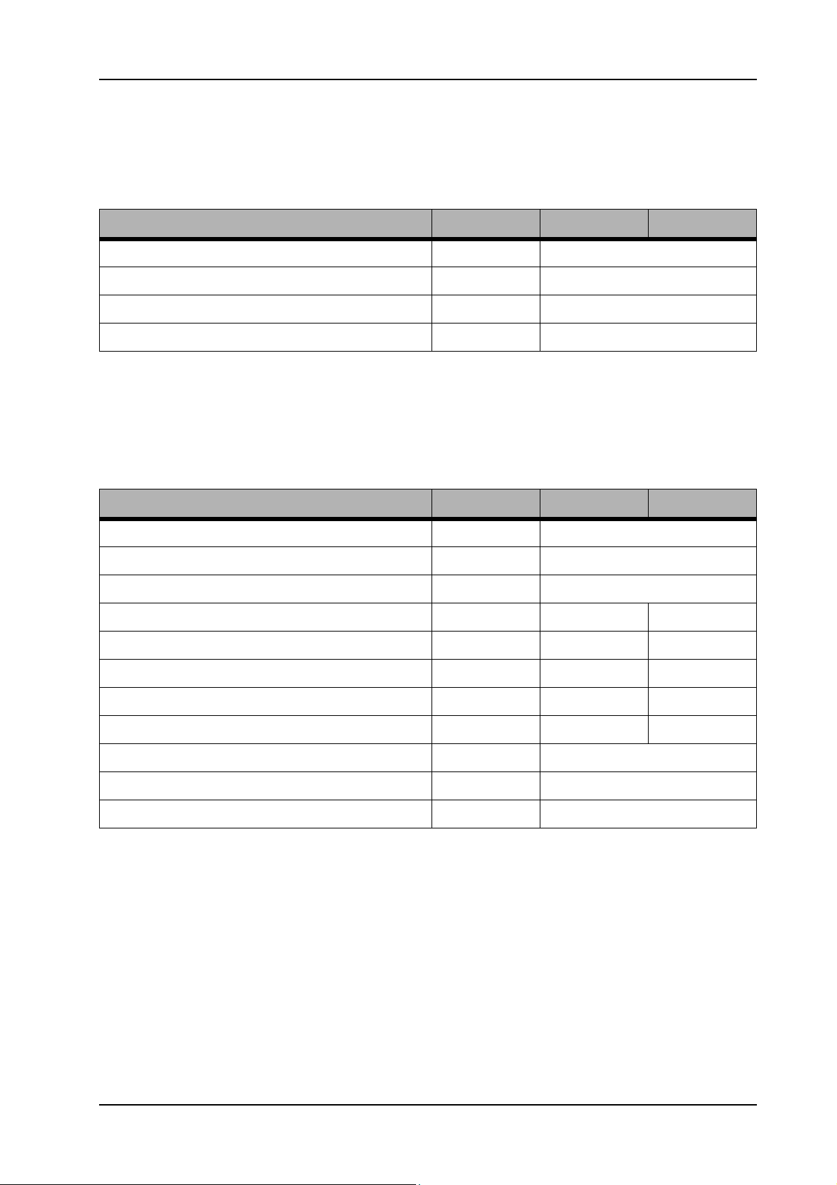
4.2.3 Machine speed
Pos. Unit Value XP-R Value XP-M
Transportation speed (km/h) 6
Cleaning speed (km/h) 5.6
Reverse speed (km/h) 2.5
Ramp max. (%) 8
Table 4: Machine speed
4.2.4 Dimensions and weights
Pos. Unit Value XP-R Value XP-M
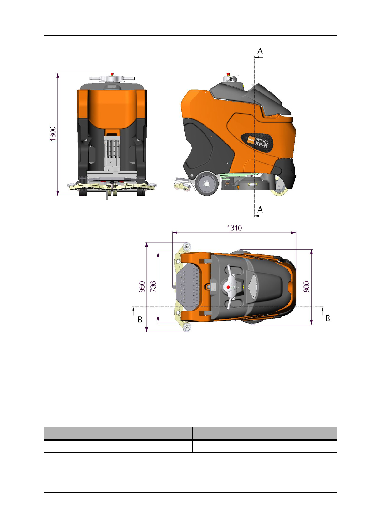
Dimensions L/W/H (mm) 1310/950/1300
Door pass through with (without) squeegee (mm) 950 (800)
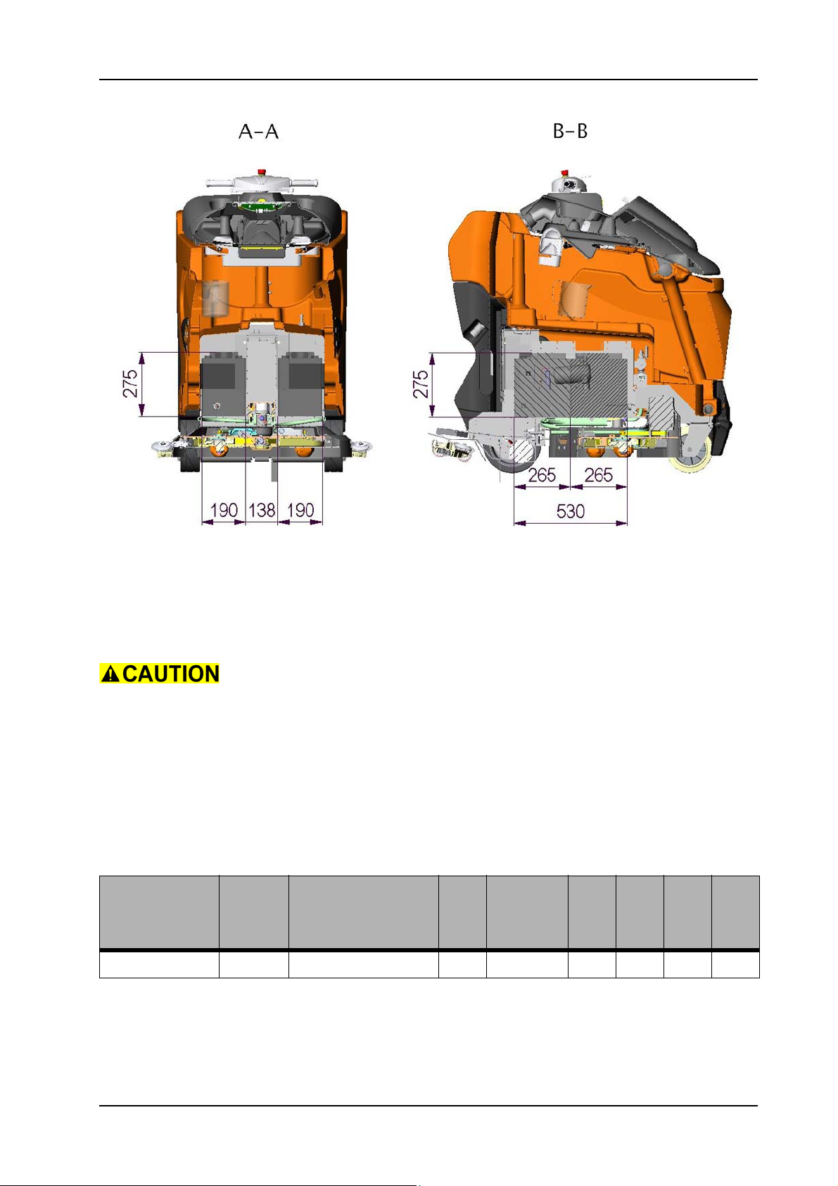
Battery compartment (two) L/W/H (mm) 530/190/275
Net weight without batteries; empty tank (kg) 207 196
Weight, ready to use (without driver) (kg) 452 438
Weight, ready for shipping (kg) 245 235
04.1 swingo XP_M_R - technical data_V1.00.fm
Max. floor pressure front (N/mm2) - -
Max. floor pressure rear (N/mm2) - -
Turn radius (between two walls) (mm) 1.9
Wheel diameter front (mm) 200
Wheel diameter rear (mm) 250
Table 5: Dimensions and weights
28. November 2014 Edition: V1.00/2014 4-3
Copyright © 2014, Diversey Care
Page 18
GTS Technical Manual
04.1 swingo XP_M_R - technical data_V1.00.fm
Picture 1: Dimensions
4.2.5 Battery
4.2.5.1 Battery compartment
Pos. Unit Value XP-R Value XP-M
Battery compartment L/W/H (mm) 530 x 190 x 275
Table 6: Battery compartment
28. November 2014 Edition: V1.00/2014 4-4
Copyright © 2014, Diversey Care
Page 19
GTS Technical Manual
Picture 2: Battery compartment
4.2.5.2 Battery specifications
Please use batteries from Exide/Sonnenschein, as this is our preferred
04.1 swingo XP_M_R - technical data_V1.00.fm
partner.
BMS machines are set to a defined charging curve. Please use only
those type of batteries.
For the correct connection of the batteries, pay attention to the
voltage of each battery and the correct connection. Therefore refer to
e-spares.
Supplier Wet/
Type
Dry
Voltage
Sonnenschein Dry GF06180V 6 180 (C5) 244 190 275 31
Ah
Length
Width
Height
Weight
Table 7: Dry (GEL) batteries
28. November 2014 Edition: V1.00/2014 4-5
Copyright © 2014, Diversey Care
Page 20

GTS Technical Manual
4.2.6 Charger
Pos. Unit Value XP-R Value XP-M
Primary (V) 230 - 240
Primary (Hz) 50 - 60
Secondary (V) 24
Secondary (A) 25
Protection class (BMS model) II
Approval CE/CB
Cable length/BMS cable (m) 3.5
Table 8: Charger
4.2.7 Brush system
Pos. Unit Value XP-R Value XP-M
Brush system (mm) 2 x 380 2 units
150 x 450
Brush motor (W) 750 2 x 130
Brush speed (rpm) 165 550
04.1 swingo XP_M_R - technical data_V1.00.fm
Brush pressure min. - max. (kg) 35-45-55 40-60-80
Brush pressure min. - max. (N/cm2) 0.16-0.2-
0.25
Brush pressure min. - max. (g/cm2) 16-20-25 33-50-67
Table 9: Brush system
0.33-0.50-
0.67
28. November 2014 Edition: V1.00/2014 4-6
Copyright © 2014, Diversey Care
Page 21
GTS Technical Manual
4.2.8 Suction power
Pos. Unit Value XP-R Value XP-M
Vacuum motor (W) 490
Max. air flow (l/s) 30
Max. vacuum (mbar) 120
Max. vacuum (kPa) 12
Table 10: Suction power
4.2.9 Additional
Pos. Unit Value XP-R Value XP-M
Dosing of cleaning solution IntelliFlow
Spot cleaning default timer 90 sec.
Squeegee lifting electrical
Brush lifting electrical
Table 11: Additional
04.1 swingo XP_M_R - technical data_V1.00.fm
4.3 Accessories & Additional parts
4.3.1 Accessories
SKU Article Machine
7514650 Scrubbing brush 450 mm XP-M
7515725 Scrubbing brush hard 450 mm XP-M
7515726 Scrubbing brush abrasive 450 mm XP-M
7514648 Pad drive harpoon grip 450 mm XP-M
7514732 TASKI contact S-Pad 450 mm (pack of 4) XP-M
7514727 TASKI S-Pad 450 mm white (pack of 10) XP-M
7514728 TASKI S-Sad 450 mm red (pack of 10) XP-M
Table 12: Accessories
28. November 2014 Edition: V1.00/2014 4-7
Copyright © 2014, Diversey Care
Page 22
GTS Technical Manual
SKU Article Machine
7514729 TASKI S-Pad 450 mm blue (pack of 10) XP-M
7514730 TASKI S-Pad 450 mm brown (pack of 10) XP-M
7514731 TASKI S-Pad 450 mm black (pack of 10) XP-M
7515372 TASKI contour diamond S-Pad 450 mm XP-M
7522220 Pad drive harpoon grip 38 cm XP-R
7522221 Scrubbing brush standard 38 cm XP-R
7522222 Scrubbing brush washed concrete 38 cm XP-R
7522223 Scrubbing brush abrasive 38 cm XP-R
7523342 Scrubbing brush water saving 38 cm XP-R
Table 12: Accessories
4.3.2 Additional parts
SKU Article Machine
8502830 Filling hose with universal coupling XP-M/XP-R
7518684 Service Station 300 XP-M/XP-R
7516242 IntelliDose kit for swingo XP XP-M/XP-R
4131268 Protection profile set XP-M/XP-R
4126922 Warning beacon (orange blinker) kit XP-M/XP-R
- Wet battery kit TASKI swingo XP XP-M/XP-R
4128981 Drive wheel 250/83 PU red XP-M/XP-R
04.1 swingo XP_M_R - technical data_V1.00.fm
4124565 Front blade 45/30x990 XP-M/XP-R
4127877 Back blade 45/4x1060 XP-M/XP-R
4128156 Front blade (option) blade 45/3x990 XP-M/XP-R
4127207 Front blade (option) blade 45/3x990 XP-M/XP-R
Table 13: Additional parts
28. November 2014 Edition: V1.00/2014 4-8
Copyright © 2014, Diversey Care
Page 23

Technical Manual
5 Mechanical
28. November 2014 Edition: V1.00/2014
Copyright © 2014, Diversey Care
Page 24
GTS Technical Manual
5.1 Control group
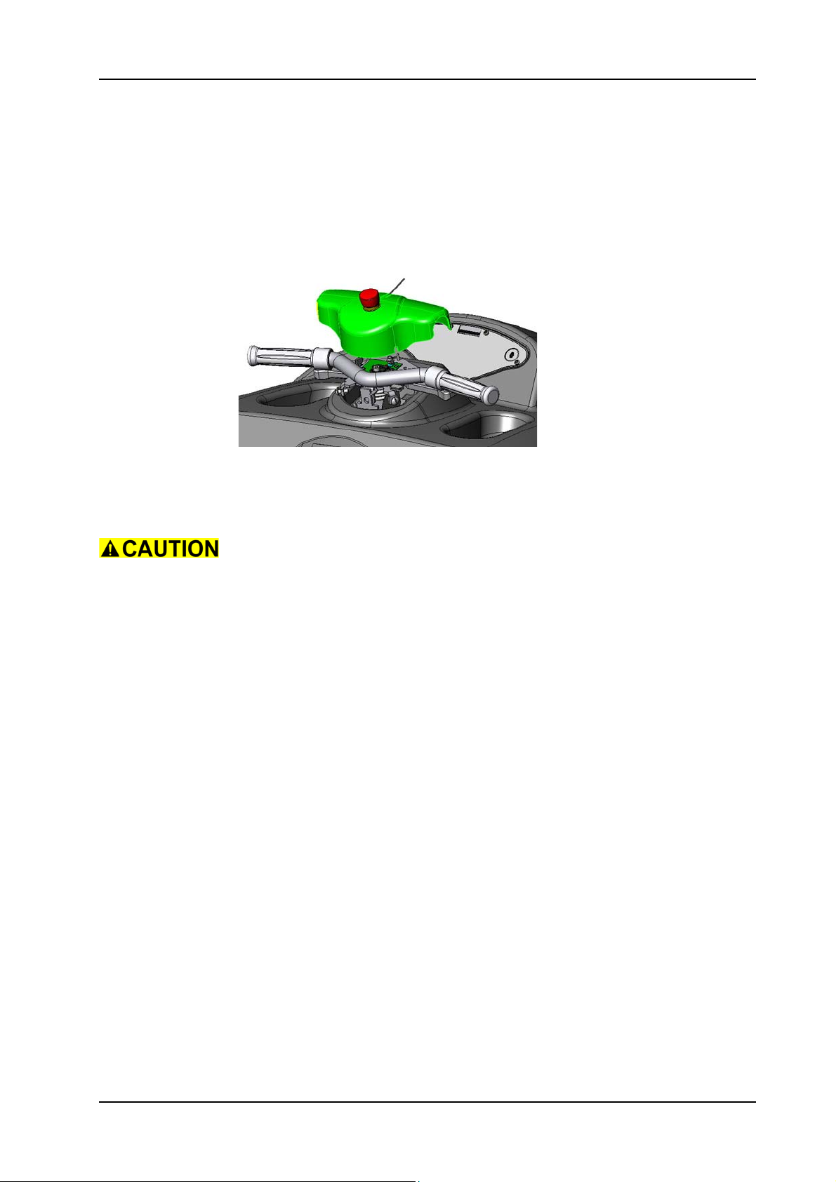
5.1.1 Removing of cover
Picture 1: Cover
05.12.13 control group - cover - XP_M_R_V1.00.fm
• Loosen the two screws (01/102) for the cover (01/103).
• Position the cover beside the guidance.
Make sure that the cables do not get damaged.
28. November 2014 Edition: V1.00/2014 5-1
Copyright © 2014, Diversey Care
Page 25
GTS Technical Manual
5.1 Control group
5.1.2 Mounting of cover
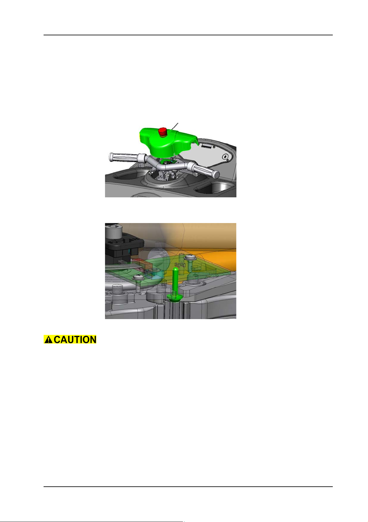
Picture 2: Cover
05.12.13 control group - cover - XP_M_R_V1.00.fm
• Put the cover back onto the two screws and tighten them.
Picture 3: Front screw position
Make sure that you hook the front screw (01/112) of the cover (01/
103) into the slot of the handle bar (01/109).
Make sure that the cover is fixed correctly, so the horn is not
activated.
Ensure that the stop actuator cable is positioned correctly along the
protection plate (01/128).
28. November 2014 Edition: V1.00/2014 5-2
Copyright © 2014, Diversey Care
Page 26
GTS Technical Manual
5.1 Control group
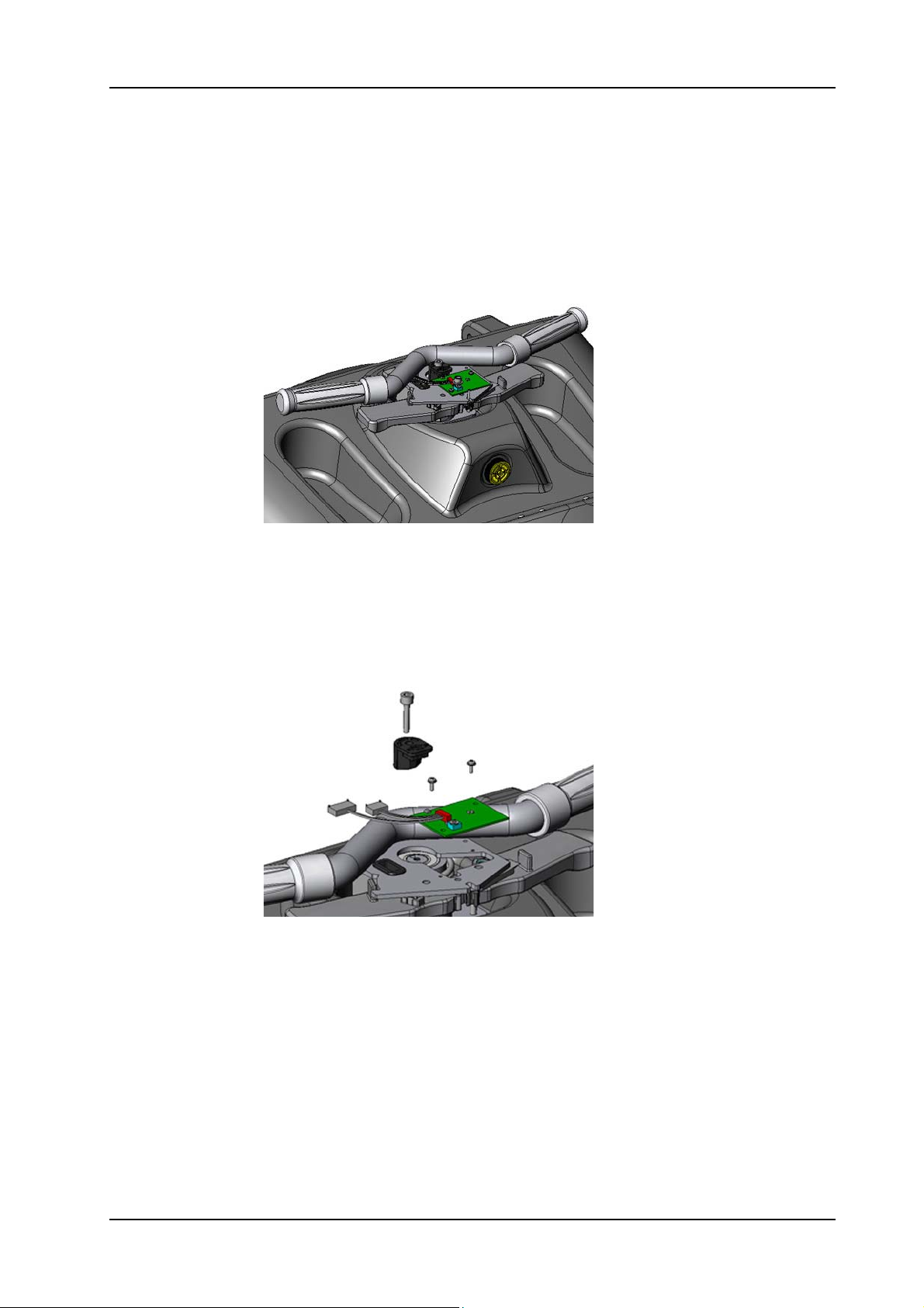
5.1.3 Removing of electronics hall sensor set
05.12.14 control group - electronics hall sensor set - XP_M_R_V1.00.fm
Picture 4: Electronics hall sensor set
• Remove the cover according to the chapter REMOVING OF
COVER.
• Remove the dashboard according to the chapter REMOVING OF
DASHBOARD (refer to „Electrical“ section).
• Remove the screw (01/115) together with the magnetic holder
(01/116).
Picture 5: Hall sensor set detail
Remarks
For an easier access to the cables remove the handle bar (01/109)
together with the torsion spring (01/117).
• Remove the two screws (01/105) together with the washers (01/
129) for the electronics hall sensor set (01/106).
• Carefully remove the complete handle (01/109) by lifting it out
from the steering support (01/120).
• Disconnect the guidance and throttle plug from the dashboard.
• Tread out the ribbon cable.
• Remove the electronics hall sensor set (01/106).
28. November 2014 Edition: V1.00/2014 5-3
Copyright © 2014, Diversey Care
Page 27
GTS Technical Manual
5.1 Control group
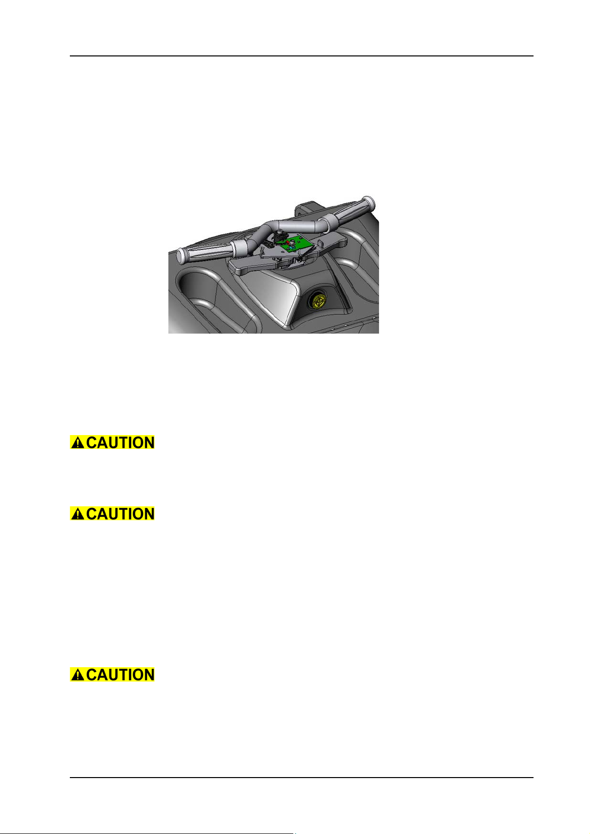
5.1.4 Mounting of electronics hall sensor set
L
05.12.14 control group - electronics hall sensor set - XP_M_R_V1.00.fm
Picture 6: Electronics hall sensor set
• Thread in the ribbon cable through the tank cover (02/102) and
connect the plugs.
• Mount the handle bar and torsion spring onto the support.
• Position the new electronics hall sensor set onto the guidance.
• Mount the two screws and washers.
Ensure that the ribbon and stop actuator cable is positioned correctly
along the protection plate (01/128).
• Mount the screw with the magnetic holder.
Make sure that the magnetic holder (01/116) is aligned in the driving
direction (positioning pin).
Service
Fix the screw (01/115) of the magnetic holder (01/116) with adhesive
locking (01/142).
• Mount the dashboard according to the chapter MOUNTING OF
DASHBOARD (refer to „Electrical“ section).
• Mount the cover according to the chapter MOUNTING OF COVER.
After working on the guidance and throttle hall sensors Teach-In the
machine.
Adjustment
Teach-In guidance and throttle as described in the Service Tool
Manual.
28. November 2014 Edition: V1.00/2014 5-4
Copyright © 2014, Diversey Care
Page 28
GTS Technical Manual
5.1 Control group
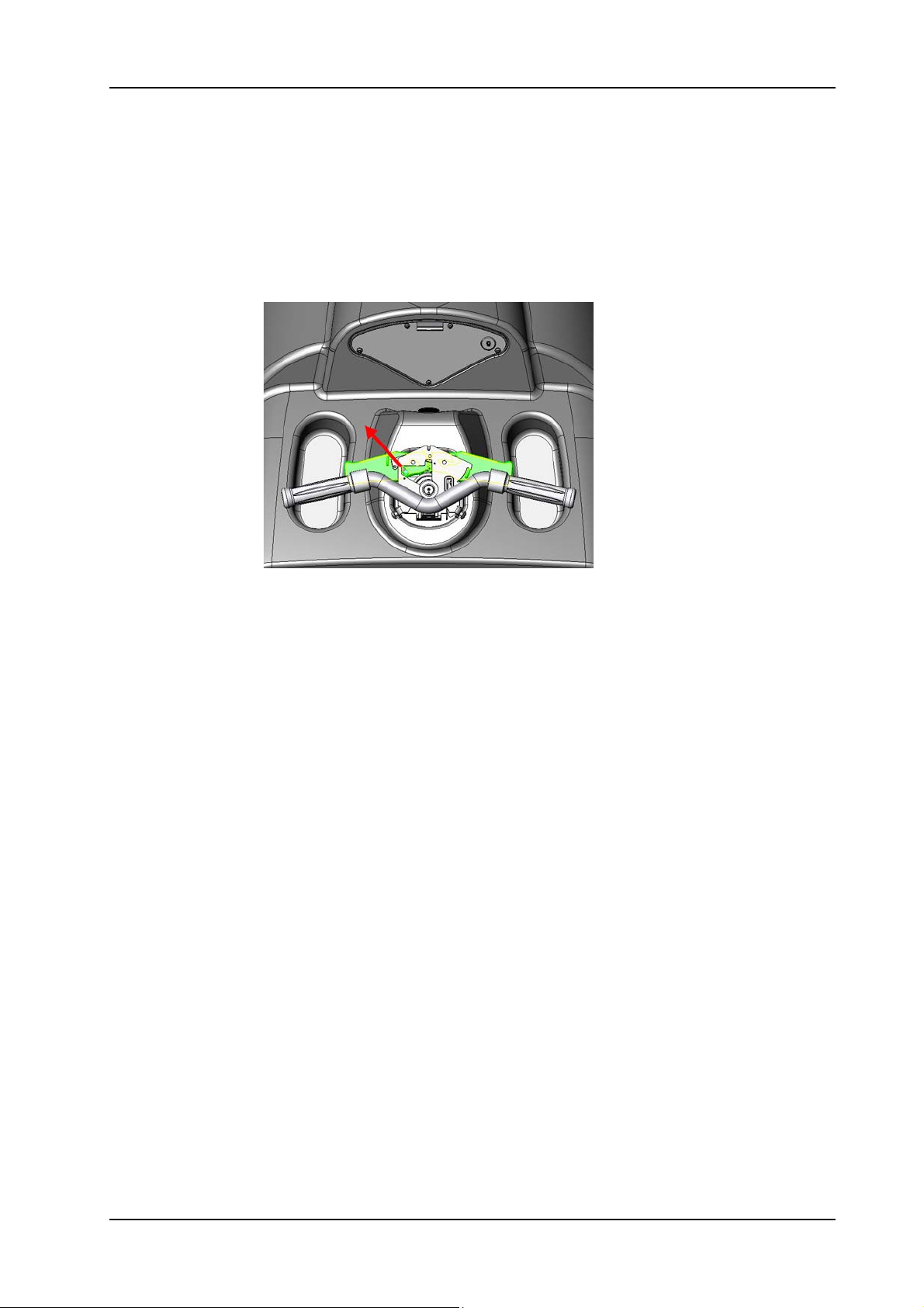
5.1.5 Removing of driving speed lever
05.12.15 control group - driving speed lever - XP_M_R_V1.00.fm
Picture 7: Driving speed levers
• Remove the cover according to chapter REMOVING OF COVER.
• Remove the screw (01/115) together with the magnetic holder
(01/116).
• Carefully remove the handle bar (01/109).
• Turn the handle bar upside down.
• Remove the tension spring (01/110).
• Remove the two circlips (01/114) from the driving speed lever
(01/113).
• Remove the two driving speed levers.
Remarks
Both levers are the same spare part.
28. November 2014 Edition: V1.00/2014 5-5
Copyright © 2014, Diversey Care
Page 29
GTS Technical Manual
5.1 Control group
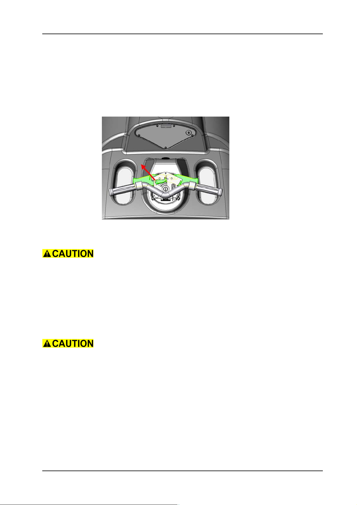
5.1.6 Mounting of driving speed lever
05.12.15 control group - driving speed lever - XP_M_R_V1.00.fm
Picture 8: Driving speed levers
• Mount the driving speed levers onto the handle.
Ensure that the magnet is positioned into the LH lever before
assembling.
The magnet is marked with a red dot. The red dot has to be positioned
in driving direction. Please see the arrow in the upper picture.
• Mount the circlips.
• Assemble the tension spring.
• Carefully mount the handle bar.
•Mount the screw together with the magnetic holder.
Ensure that the ribbon and stop actuator cable is positioned correctly
along the protection plate (01/128).
• Complete assembling of the cover according to the chapter
MOUNTING OF COVER.
28. November 2014 Edition: V1.00/2014 5-6
Copyright © 2014, Diversey Care
Page 30
GTS Technical Manual
5.2 Upper part
5.2.1 Removing of vacuum motor
05.18.24 upper part - vacuum motor - XP_M_R_V1.00.fm
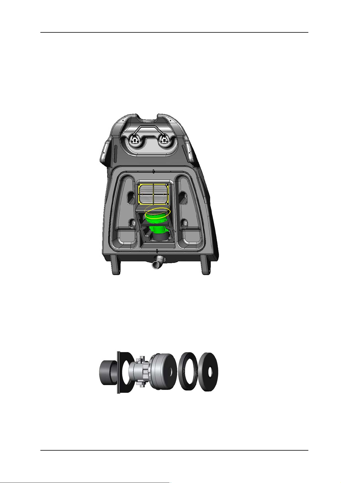
Picture 9: Vacuum motor
• Open tank cover (02/102).
• Remove the six screws (02/108) for the cover plate (02/107).
• Remove the cover plate.
• Disconnect the vacuum motor cable from the connection block
(02/112).
• Remove the vacuum motor (02/109) by pulling it out from the
tank cover.
Picture 10: Vacuum motor details
28. November 2014 Edition: V1.00/2014 5-7
Copyright © 2014, Diversey Care
Page 31
GTS Technical Manual
5.2 Upper part
5.2.2 Mounting of vacuum motor
05.18.24 upper part - vacuum motor - XP_M_R_V1.00.fm
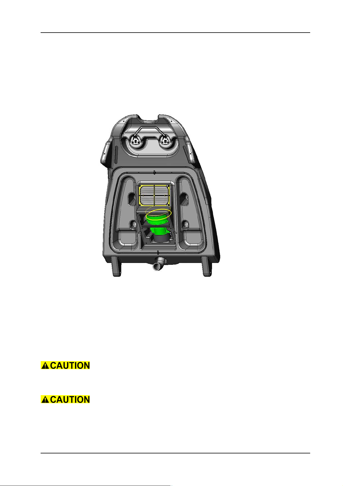
Picture 11: Vacuum motor
• Mount the vacuum motor.
Service
Apply silicone paste onto the sealing ring (02/111).
• Connect wires to the connection block.
• Mount the cover plate.
Ensure that the cover gasket (02/106) is in good condition.
•Mount the six screws for the cover plate.
Make sure that the screws of the cover plate are fixed properly, so that
the loops of the fresh water foil tank (03/123) do not get damaged.
•Close tank cover.
28. November 2014 Edition: V1.00/2014 5-8
Copyright © 2014, Diversey Care
Page 32
GTS Technical Manual
5.2 Upper part
5.2.3 Removing of tank cover
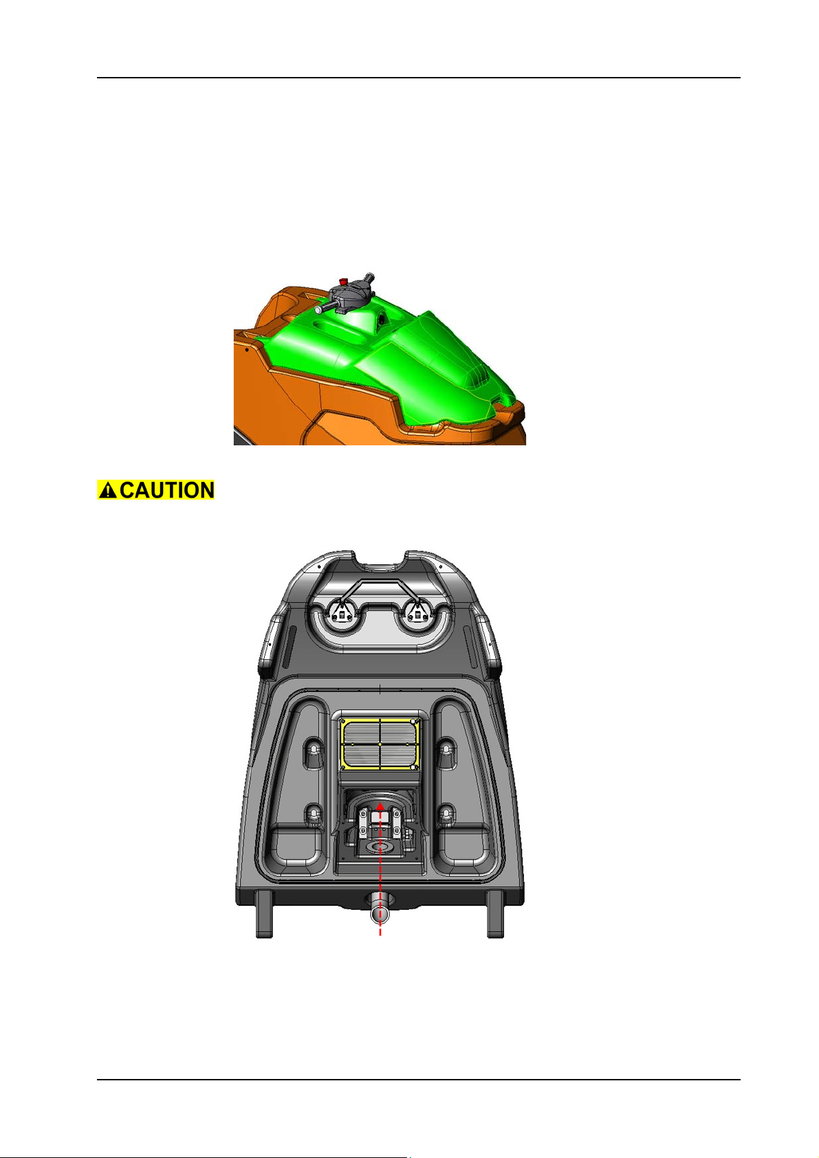
Picture 12: Tank cover
05.18.25 upper part - tank cover - XP_M_R_V1.00.fm
If the hose (02/101) has to be removed, it has to be done from the
inside of the tank cover (Refer to the following picture).
Picture 13: Tank cover hose
• Remove the dashboard according to the chapter REMOVING OF
DASHBOARD (refer to „Electrical“ section).
• Disconnect the patch, emergency loop an ground cable from the
dashboard.
28. November 2014 Edition: V1.00/2014 5-9
Copyright © 2014, Diversey Care
Page 33

GTS Technical Manual
Remarks
For the dashboard connections refer to the chapter DASHBOARD
CONNECTIONS in the „Electrical“ section.
• Open tank cover (02/102).
• Remove the vacuum motor according to the chapter REMOVING
OF VACUUM MOTOR.
• Disconnect wires from the electronics on the connection block
(02/112).
• Pull out the hose from the tank set (03/104).
• Thread out all the cables from the hose.
• Pull out the hose from the tank cover.
• Remove the hinge bolts (03/135) and distance disc (03/122).
• Remove tank cover (02/102).
• According to what you need to exchange, remove the existing
parts from the tank cover and place it on the new one.
05.18.25 upper part - tank cover - XP_M_R_V1.00.fm
28. November 2014 Edition: V1.00/2014 5-10
Copyright © 2014, Diversey Care
Page 34
GTS Technical Manual
5.2 Upper part
5.2.4 Mounting of tank cover
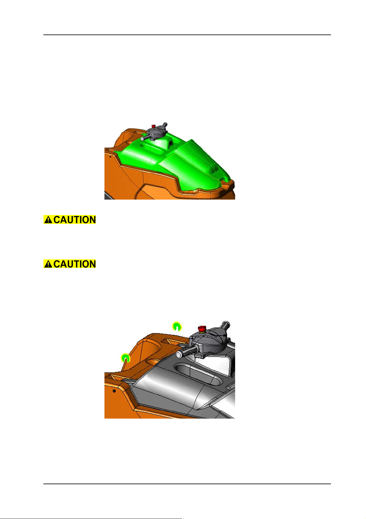
Picture 14: Tank cover
05.18.25 upper part - tank cover - XP_M_R_V1.00.fm
Assemble the tank cover locking bow (02/118) at the end of this
sequence.
• Position the tank cover correctly on the tank.
Make sure that the sealings are nicely positioned.
• Drill the hole for the tank axle without pressing the tank cover
down onto the tank (drill with 12 mm).
• Mount the two hinge bolts.
• Position the distance disc (03/122).
Picture 15: Distance disc
28. November 2014 Edition: V1.00/2014 5-11
Copyright © 2014, Diversey Care
Page 35

GTS Technical Manual
Make sure that the tank cover is positioned in the centre of the tank.
• Open tank cover.
• Mount the hose onto the tank cover.
• Thread in the cables to the control group.
Protect the communication cable connector with tape to prevent
damages.
• Connect the wires from the electronics to the connection block
(02/112).
• Mount the vacuum motor according to the chapter MOUNTING
OF VACUUM MOTOR.
•Close tank cover.
• Connect the patch, emergency loop and ground cable to the
dashboard.
• Mount the dashboard according to the chapter MOUNTING OF
DASHBOARD.
05.18.25 upper part - tank cover - XP_M_R_V1.00.fm
Remarks
Ensure that the cables are positioned that way, that they can not be
squeezed by the tank cover.
Adjustment
Adjust the tank cover lock and ensure a proper opening and closing
of the tank cover.
28. November 2014 Edition: V1.00/2014 5-12
Copyright © 2014, Diversey Care
Page 36
GTS Technical Manual
5.2 Upper part
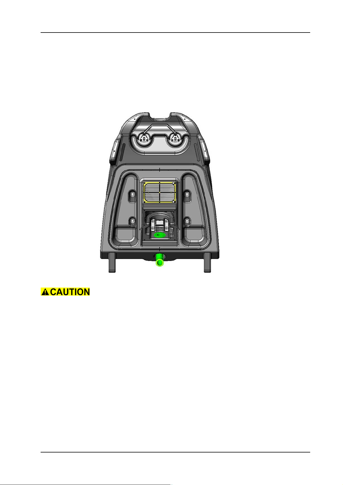
5.2.5 Removing of hose
Picture 16: Cable hose
05.18.26 upper part - hose - XP_M_R_V1.00.fm
If the hose (02/101) has to be removed, it has to be done from the
inside of the tank cover.
• Remove dashboard according to the chapter REMOVING OF
DASHBOARD (refer to „Electrical“ section).
• Disconnect the patch, emergency loop an ground cable from the
dashboard.
Remarks
For the dashboard connections refer to the chapter DASHBOARD
CONNECTIONS in the „Electrical“ section.
• Remove the vacuum motor according to the chapter REMOVING
OF VACUUM MOTOR.
• Disconnect the vacuum motor cable from the electronics on the
connection block (02/112).
• Carefully pull out the cable hose (02/101) from the tank set (03/
104).
• Thread out the cables from the cable hose.
• Pull out the cable hose from the tank cover (02/102).
28. November 2014 Edition: V1.00/2014 5-13
Copyright © 2014, Diversey Care
Page 37
GTS Technical Manual
5.2 Upper part
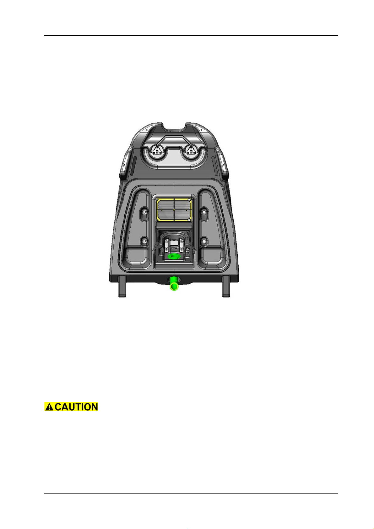
5.2.6 Mounting of hose
Picture 17: Cable hose
05.18.26 upper part - hose - XP_M_R_V1.00.fm
• Mount the cable hose into the tank cover.
• Thread in the cables.
• Mount the cable hose into the tank set.
• Connect the vacuum motor cable from the electronics onto the
connection block.
• Mount the vacuum motor according to the chapter MOUNTING
OF VACUUM MOTOR.
• Connect the cables onto the dashboard.
• Mount dashboard according to the chapter MOUNTING OF
DASHBOARD (refer to „Electrical“ section).
Protect the communication cable connector with tape to prevent
damages.
28. November 2014 Edition: V1.00/2014 5-14
Copyright © 2014, Diversey Care
Page 38
GTS Technical Manual
5.3 Tank
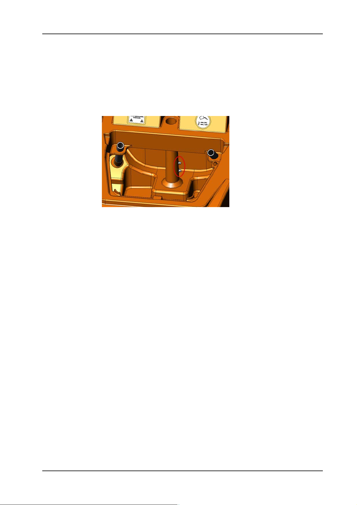
5.3.1 Removing of waste water sensor
05.70.15 tank - waste water sensor - XP_M_R_V1.00.fm
Picture 18: Waste water sensor
• Open tank cover (02/102).
• Disconnect the wire (13/107) of the waste water detector sensor
at the power electronic (04/108).
• Remove the two sensor bolts (03/131).
• Disconnect the sensor wires from the bolts.
• Thread out the wires.
28. November 2014 Edition: V1.00/2014 5-15
Copyright © 2014, Diversey Care
Page 39
GTS Technical Manual
5.3 Tank
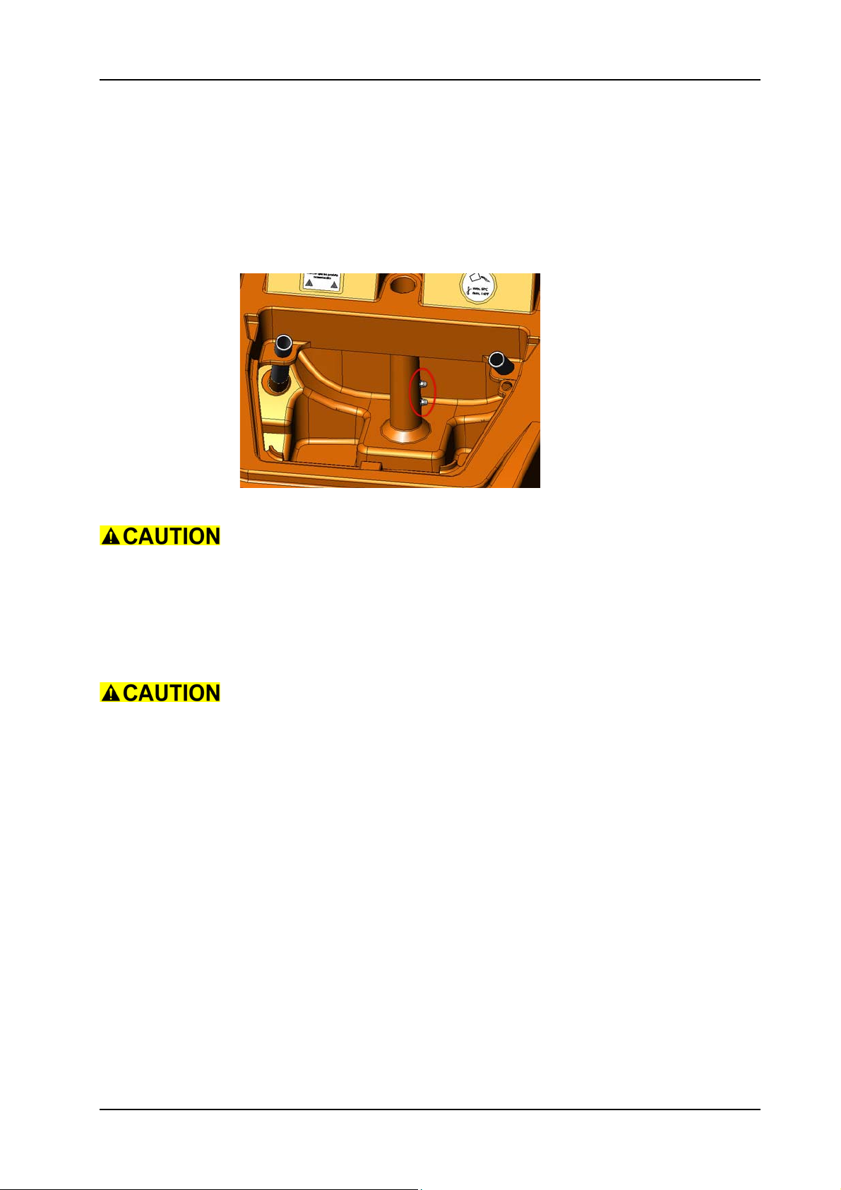
5.3.2 Mounting of waste water sensor
05.70.15 tank - waste water sensor - XP_M_R_V1.00.fm
Picture 19: Waste water sensor
Start to install the waste water sensor from position of the sensor
inside the tank, down to the power electronics.
• Thread in the wires (13/107) from the sensor down to the power
electronics.
• Connect the sensor bolts to the sensor wires.
• Tighten the sensor bolts.
Tighten the sensor bolts carefully, not to damage the tank.
• Position the sensor plug (13/108) on the wires.
• Connect the sensor plug to the power electronics.
•Close tank cover.
28. November 2014 Edition: V1.00/2014 5-16
Copyright © 2014, Diversey Care
Page 40
GTS Technical Manual
5.3 Tank
5.3.3 Removing of tank set
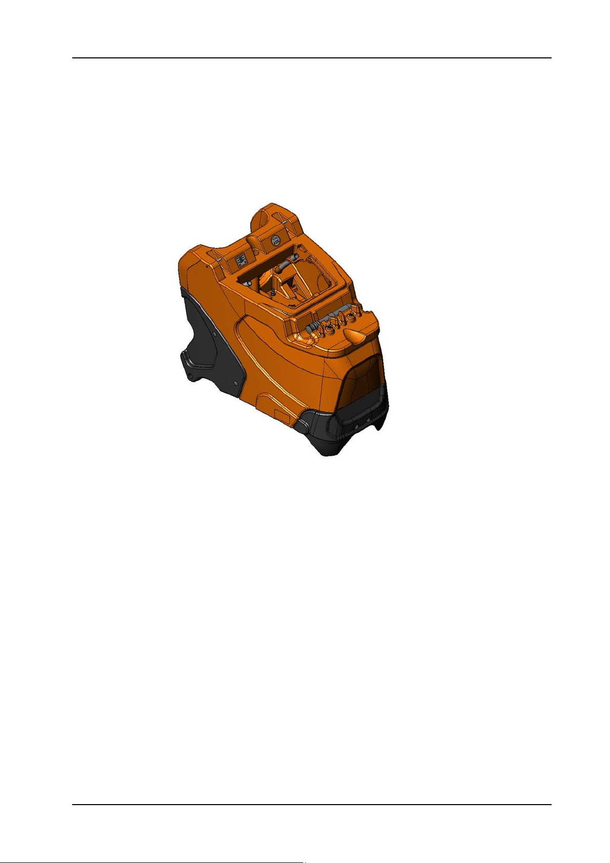
Picture 20: Tank set
• Remove the power electronics according to the chapter
05.70.16 tank - tank set - XP_M_R_V1.00.fm
REMOVING OF POWER ELECTRONICS.
• Remove the waste water sensor according to the chapter
REMOVING OF WASTE WATER SENSOR.
• Remove the tank cover according to the chapter REMOVING OF
TANK COVER.
• Disconnect main cable (04/120) from charger.
• Remove charger main cable from wiring harness.
• Remove the two screws (12/104) and washers (12/103) for the
cable guiding strip (12/101) at the tank.
• Remove the hose clamp (05/111) from the fresh water hose (05/
107).
• Remove the fresh water hose from the tank.
• Thread out the cables from the tank set.
• Remove the 4 screws (04/107) from the two flange bolt (04/
106).
• Remove the two flange bolts.
• Remove complete tank.
• According to what you need to exchange, remove the existing
parts from the tank and place it on the new one.
28. November 2014 Edition: V1.00/2014 5-17
Copyright © 2014, Diversey Care
Page 41
GTS Technical Manual
5.3 Tank
5.3.4 Mounting of tank set
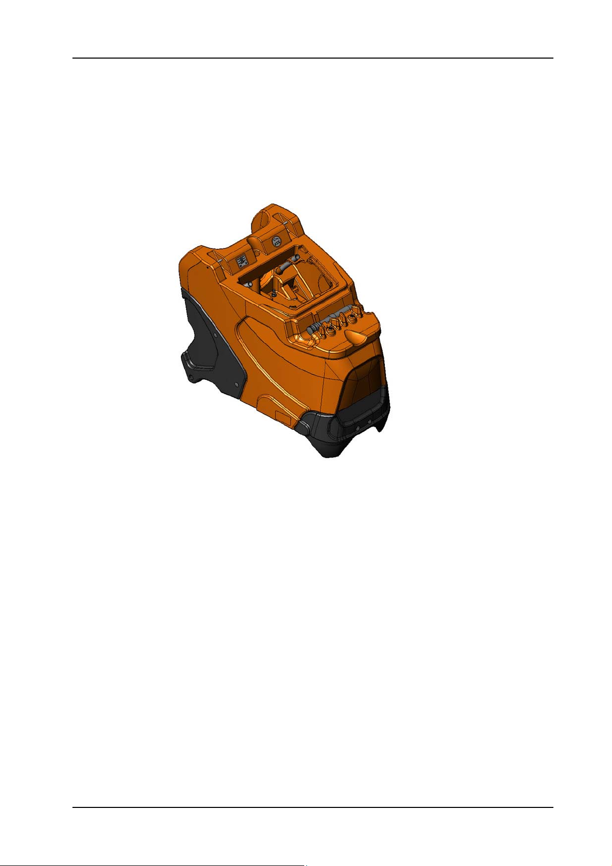
Picture 21: Tank set
• Position the tank on the chassis.
05.70.16 tank - tank set - XP_M_R_V1.00.fm
• Mount the two flange bolts.
• Mount the 4 fixation screws for the flange bolt.
• Mount the fresh water hose onto the tank.
• Mount the hose clamp onto the fresh water hose.
• Mount the cable guiding strip on the tank.
• Mount the charger main cable at the wiring harness.
• Connect the main cable on to the charger.
• Mount the tank cover according to the chapter MOUNTING OF
TANK COVER.
• Mount the waste water sensor according to the chapter
MOUNTING OF WASTE WATER SENSOR.
• Mount the power electronics according to the chapter
MOUNTING OF POWER ELECTRONICS.
28. November 2014 Edition: V1.00/2014 5-18
Copyright © 2014, Diversey Care
Page 42
GTS Technical Manual
5.4 Base
5.4.1 Removing of castor wheel
05.44.22 base - castor wheel - XP_M_R_V1.00.fm
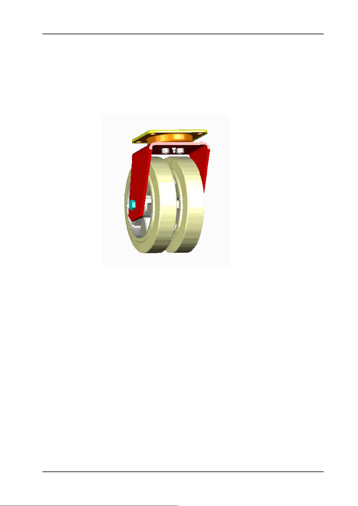
Picture 22: Castor wheel
• Lay the machine on the LH side or use a jack to lift it.
• Remove the four screws (04/141) with the washers (04/140).
• Remove the complete castor wheel (04/117).
Remarks
The castor wheel complete is only as a set available.
28. November 2014 Edition: V1.00/2014 5-19
Copyright © 2014, Diversey Care
Page 43
GTS Technical Manual
5.4 Base
5.4.2 Mounting of castor wheel
05.44.22 base - castor wheel - XP_M_R_V1.00.fm
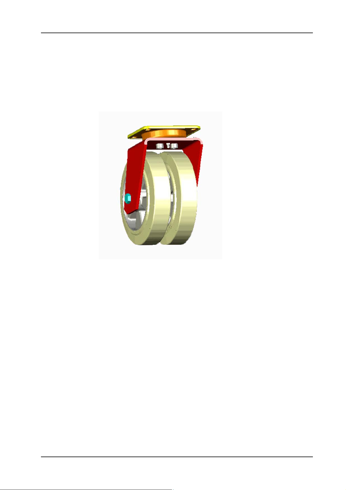
Picture 23: Castor wheel
• Assemble castor wheel.
• Mount the 4 fixation screws together with the washers.
• Lift up the machine or lower the jack.
Service
Lubricate the castor wheel bearing with ball bearing grease (04/164).
Fix the screws (04/141) of the castor wheel with adhesive locking (04/
165).
28. November 2014 Edition: V1.00/2014 5-20
Copyright © 2014, Diversey Care
Page 44
GTS Technical Manual
5.4 Base
5.4.3 Removing of drive gear
05.44.23 base - drive gear - XP_M_R_V1.00.fm
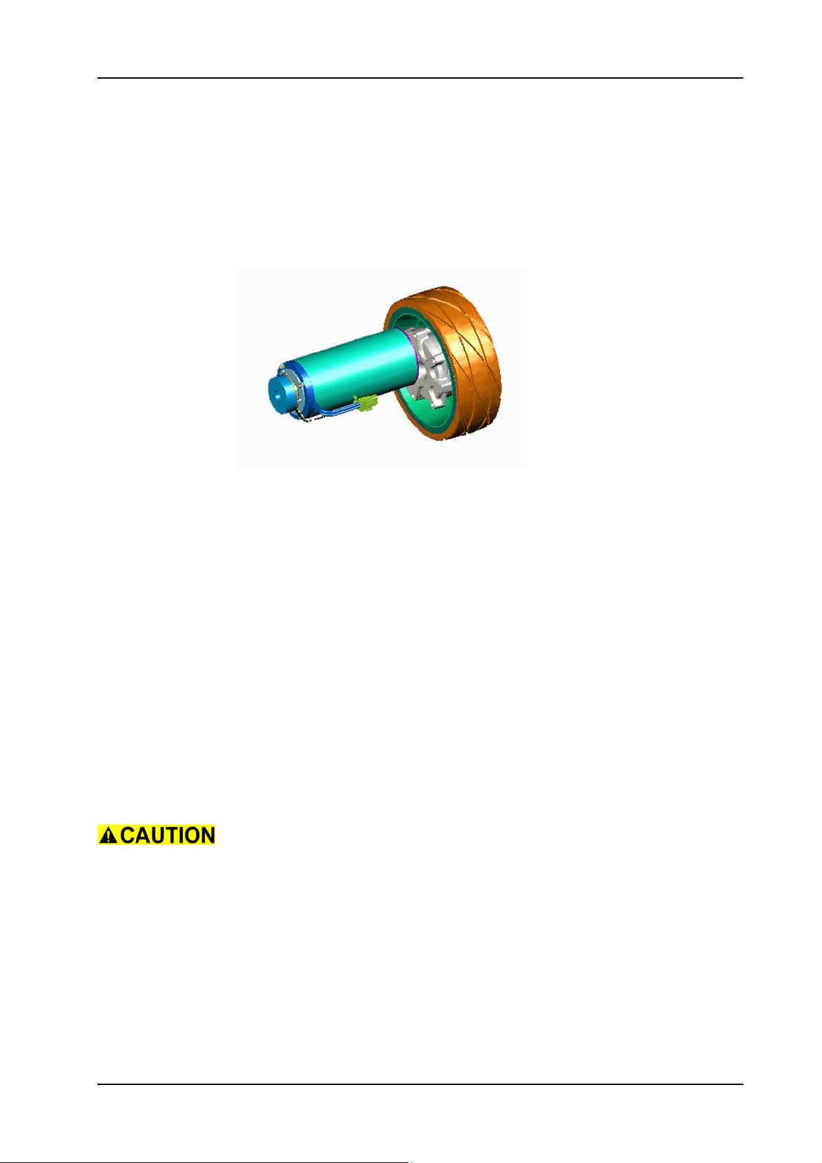
Picture 24: Traction unit
• Lay the machine on the LH side or use a jack to lift it.
• Disconnect the drive gear and break plug according to the
chapter REMOVING OF POWER ELECTRONICS (refer to „Electrical“
section).
• Remove the three screws (04/107) for the traction wheel (04/
130).
• Remove traction wheel.
• Remove the cable ties of the cables from the break and drive
gear.
• Thread out the cable.
• Remove the four screws (04/105) for drive gear.
• Remove the drive gear.
Remarks
To get better access to the drive gear fixation screws, you can
dismount the step board.
Before laying the machine on the side remove the brush unit, so it
does not get damaged.
28. November 2014 Edition: V1.00/2014 5-21
Copyright © 2014, Diversey Care
Page 45
GTS Technical Manual
5.4 Base
5.4.4 Mounting of drive gear
05.44.23 base - drive gear - XP_M_R_V1.00.fm
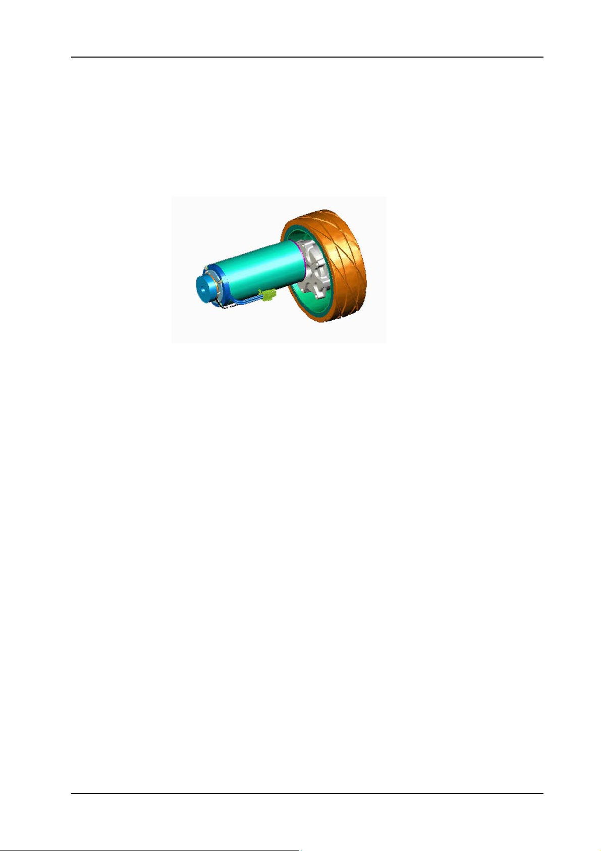
Picture 25: Traction unit
• Position the drive gear.
• Mount the four screws for drive gear.
• Thread in the cable.
• Mount the cable ties on to the cables of the drive gear and
breaks.
• Mount traction wheel.
• Mount the three screws for the traction wheel.
• Complete assembling of the plug according to the chapter
MOUNTING OF THE POWER ELECTRONICS (refer to „Electrical“
section).
• Lift up the machine or lower the jack.
Remarks
Lay the machine on the RH side and repeat the removing and
mounting steps of the chapter DRIVE GEAR.
Service
Tighten the screws (04/107) of the wheel with 18 Nm.
Fix the screws (04/107) and (04/105) with adhesive locking (04/165).
28. November 2014 Edition: V1.00/2014 5-22
Copyright © 2014, Diversey Care
Page 46
GTS Technical Manual
5.4 Base
5.4.5 Removing of step board
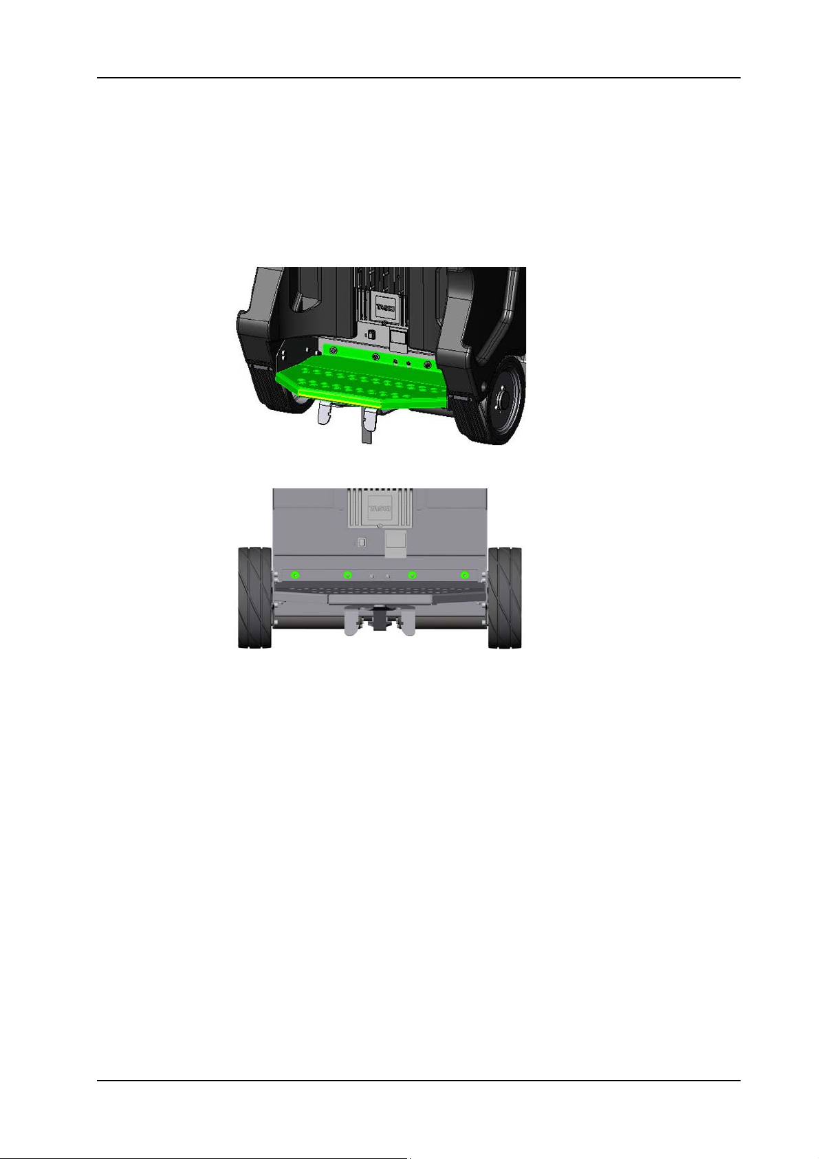
Picture 26: Step board
Picture 27: Step board fixation
05.44.24 base -step board - XP_M_R_V1.00.fm
• Remove the two step board fixation screws (04/170) and the two
nuts (04/169) together with the washers (04/168).
• Remove step board (04/145).
28. November 2014 Edition: V1.00/2014 5-23
Copyright © 2014, Diversey Care
Page 47
GTS Technical Manual
5.4 Base
5.4.6 Mounting of step board
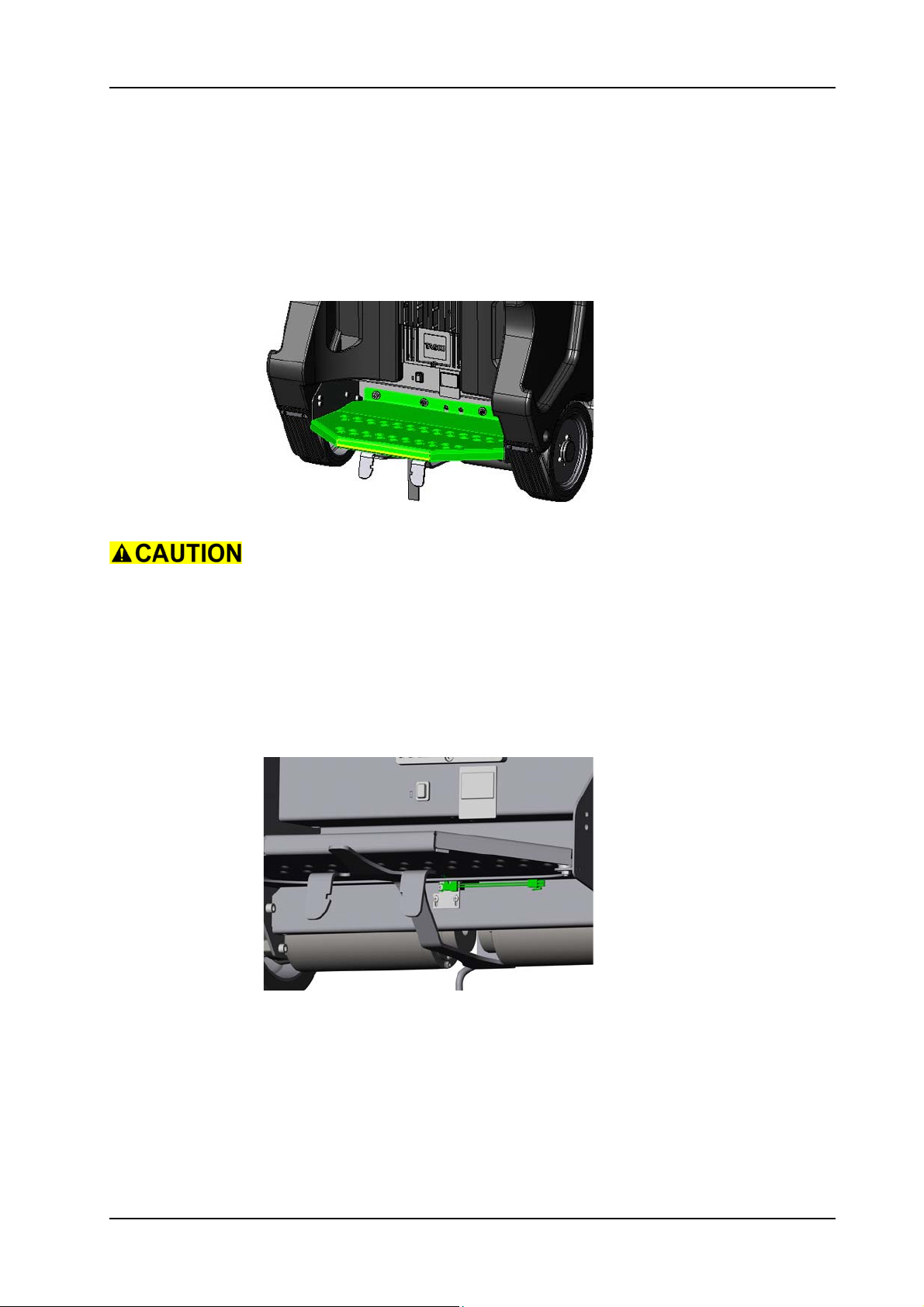
Picture 28: Step board
Loosen the two screws (04/161) for the plate (04/166) and push the
limit switch (04/163) down, not to damage the limit switch when
mounting the step board.
•Mount step board.
• Mount the two step board fixation screws and the two nuts
together with the washers.
• Move the plate (04/166) with the limit switch up to the step
board.
• Tighten the two screws of the limit switch plate.
05.44.24 base -step board - XP_M_R_V1.00.fm
Picture 29: Limit switch
Adjustment
The step board switch is correctly adjusted if it activates at a pressure
of 30 - 40 kg.
28. November 2014 Edition: V1.00/2014 5-24
Copyright © 2014, Diversey Care
Page 48
GTS Technical Manual
5.5 Fresh water circle
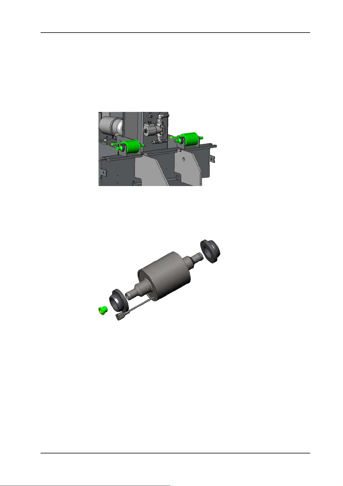
5.5.1 Removing of pumps
Picture 30: Pump
05.62.12 fresh water circle - pump - XP_M_R_V1.00.fm
• Open tank set (03/104) by releasing the screw (12/119).
• Remove the hose clamps (05/111) on both sides of pump (05/
119).
• Remove the hoses (05/113, XP-M:05/121&122, XP-R:11/149).
• Disconnect wires of the pump.
Picture 31: Pump detail
• Remove the pumps (05/119).
• Remove the two rubber bushes (05/120).
28. November 2014 Edition: V1.00/2014 5-25
Copyright © 2014, Diversey Care
Page 49
GTS Technical Manual
5.5 Fresh water circle
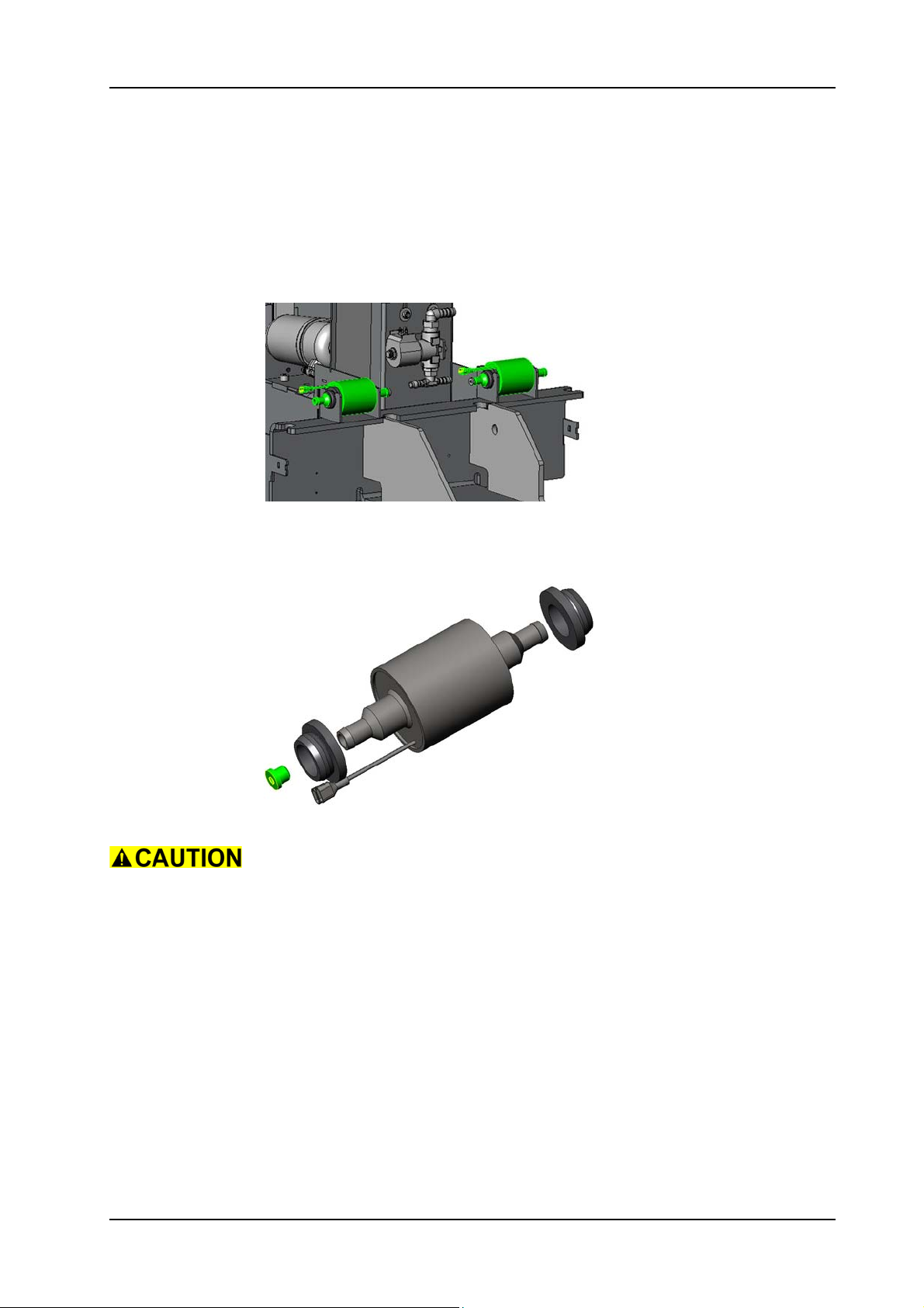
5.5.2 Mounting of pumps
Picture 32: Pump
05.62.12 fresh water circle - pump - XP_M_R_V1.00.fm
• Mount the two rubber bushes onto the pump.
•Mount the pump.
Picture 33: Pump detail
Ensure that the pump is build in according to the water flow. The
arrow on the pump indicates the water flow direction.
Ensure that the reduction bush is mounted into the input area of the
pump.
• Connect wires of the pump.
•Mount the hoses.
• Mount the hose clamps on both sides of pump.
• Close the tank set.
Service
Apply silicone paste to the rubber bushes (05/120).
28. November 2014 Edition: V1.00/2014 5-26
Copyright © 2014, Diversey Care
Page 50
GTS Technical Manual
5.5 Fresh water circle
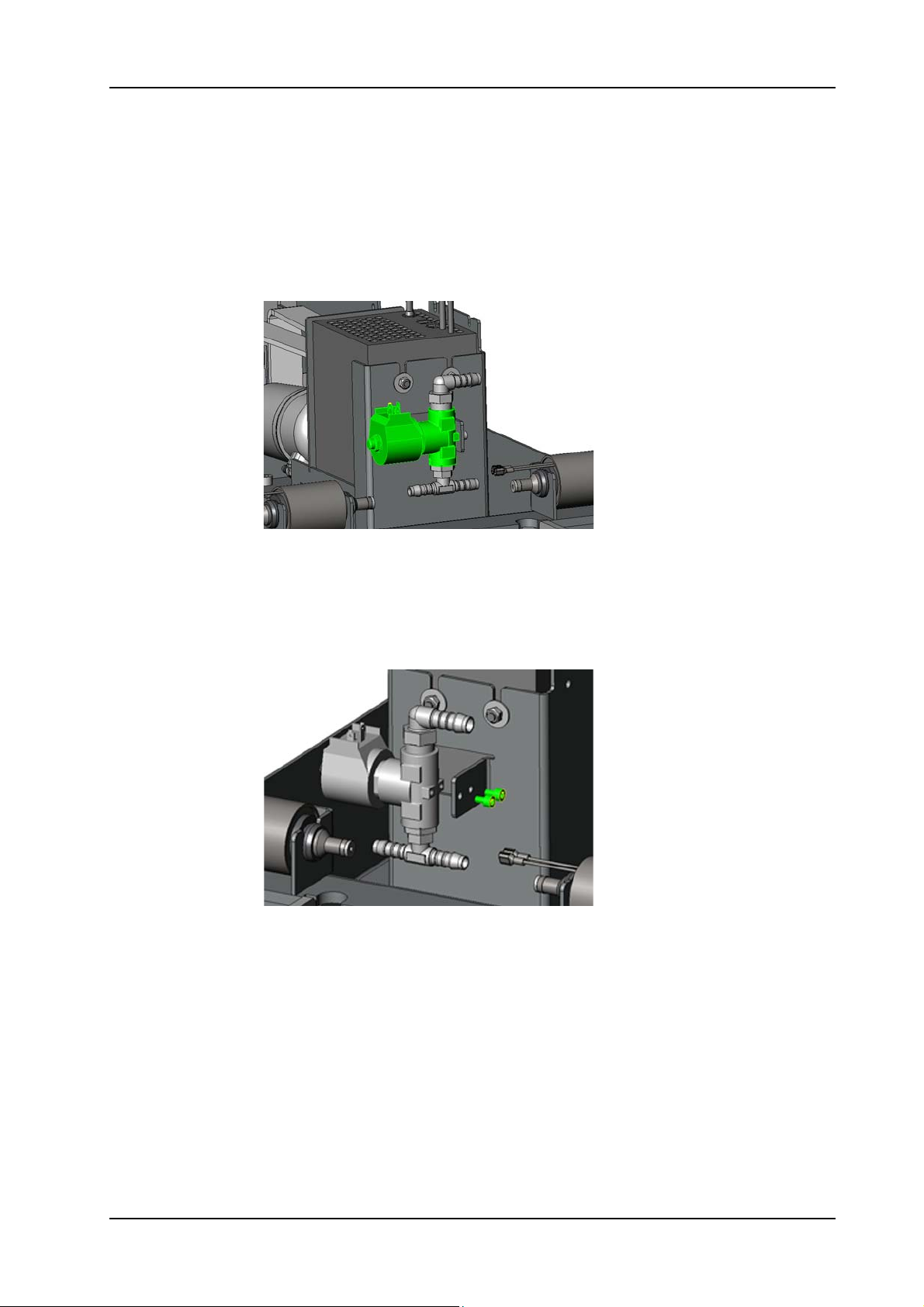
5.5.3 Removing of magnetic valve
05.62.13 fresh water circle - magnetic valve - XP_M_R_V1.00.fm
Picture 34: Magnetic valve
• Open tank set (03/104) by releasing the screw (12/119).
• Remove the hose clamp (05/111) and hose (05/107) from the
angle nipple (05/114).
• Remove the hose clamps (05/111) and hose (05/113) on both
sides of the T-pipe connection (05/118).
Picture 35: Magnetic valve fixation
• Disconnect the wires on the magnetic valve (05/112).
• Remove the two screws (05/115) from the magnetic valve.
• Remove the magnetic valve.
• According to what you need to exchange, remove the existing
parts from the magnetic valve and place it on the new one.
28. November 2014 Edition: V1.00/2014 5-27
Copyright © 2014, Diversey Care
Page 51
GTS Technical Manual
5.5 Fresh water circle
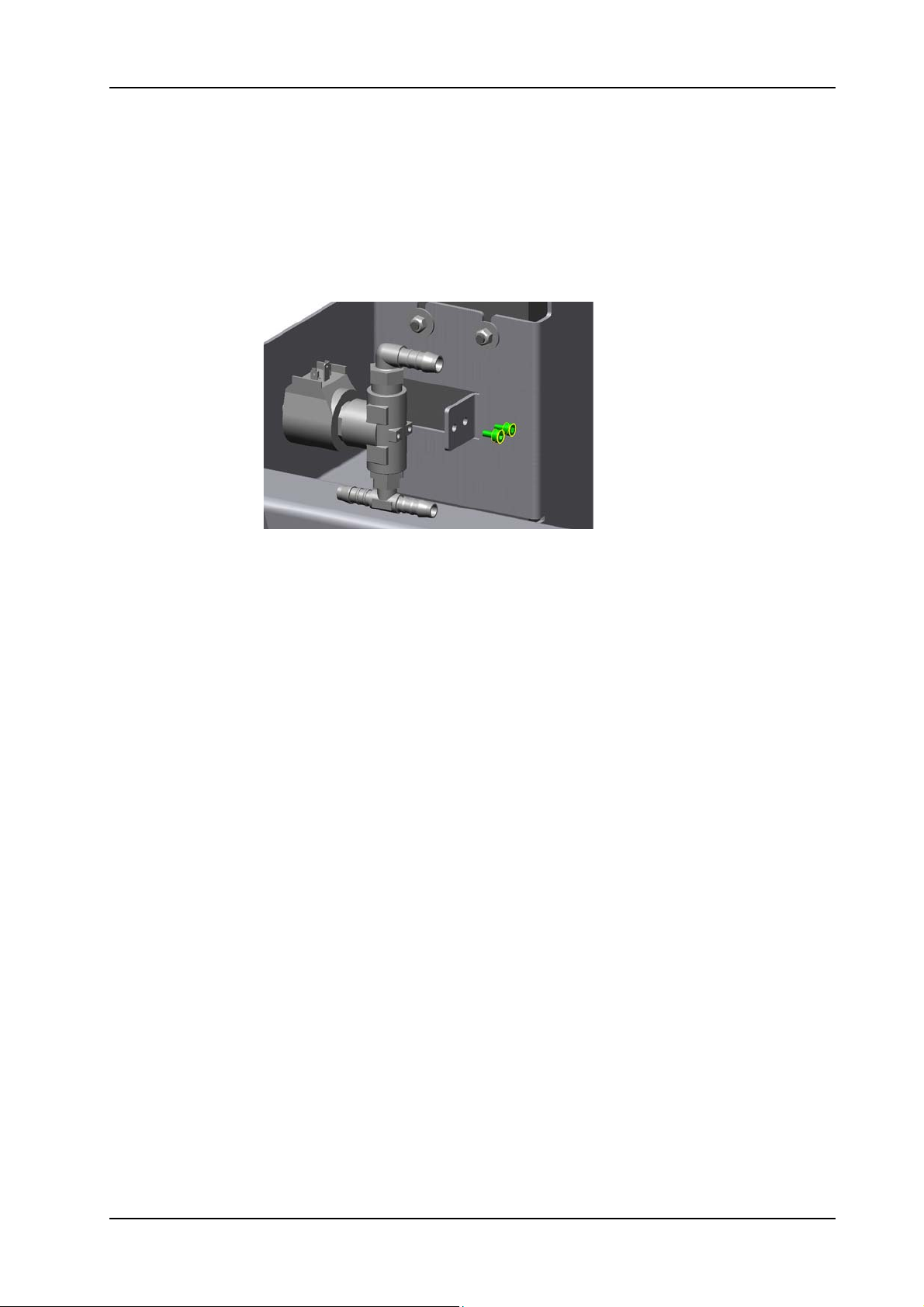
5.5.4 Mounting of magnetic valve
05.62.13 fresh water circle - magnetic valve - XP_M_R_V1.00.fm
Picture 36: Magnetic valve fixation
• Take the magnetic valve and make sure that the two connectors
(05/118) and (05/114) are mounted.
• Position the magnetic valve.
• Mount the two screws onto the magnetic valve.
• Connect the wires on the magnetic valve.
• Mount the hoses and the hose clamps
•Close tank set.
28. November 2014 Edition: V1.00/2014 5-28
Copyright © 2014, Diversey Care
Page 52
GTS Technical Manual
5.6 Squeegee lowering mechanism
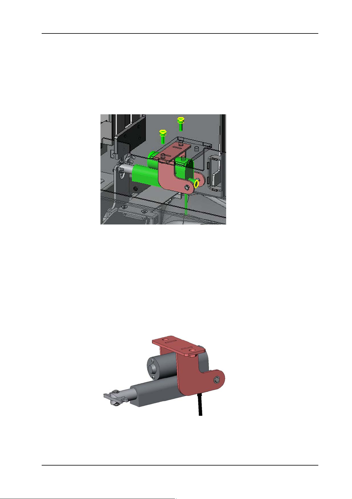
5.6.1 Removing of squeegee linear drive
Picture 37: Squeegee lifting motor
Remarks
Remove the squeegee from the machine. This will release the tension
on the squeegee swinging arm (06/126).
• Remove the brush unit linear drive according to the chapter
REMOVING OF BRUSH UNIT LINEAR DRIVE.
• Disconnect the plug of the linear drive (06/137) at the top of the
chassis (04/110) and thread out the cable.
• Remove the two screws (06/101) from the chassis (04/110).
05.36.15 squeegee lowering mechanism - linear drive - XP_M_R_V1.00.fm
• Weave out the squeegee linear drive together with the linear
drive holder (06/102) from the swinging arm (06/126).
Picture 38: Squeegee lifting motor details
• Remove the circlip (06/134) on one side of the bolt (06/103).
• Pull out the bolt and remove the linear drive.
• According to what you need to exchange, remove the existing
parts from the linear drive and place it on the new one.
28. November 2014 Edition: V1.00/2014 5-29
Copyright © 2014, Diversey Care
Page 53
GTS Technical Manual
5.6 Squeegee lowering mechanism
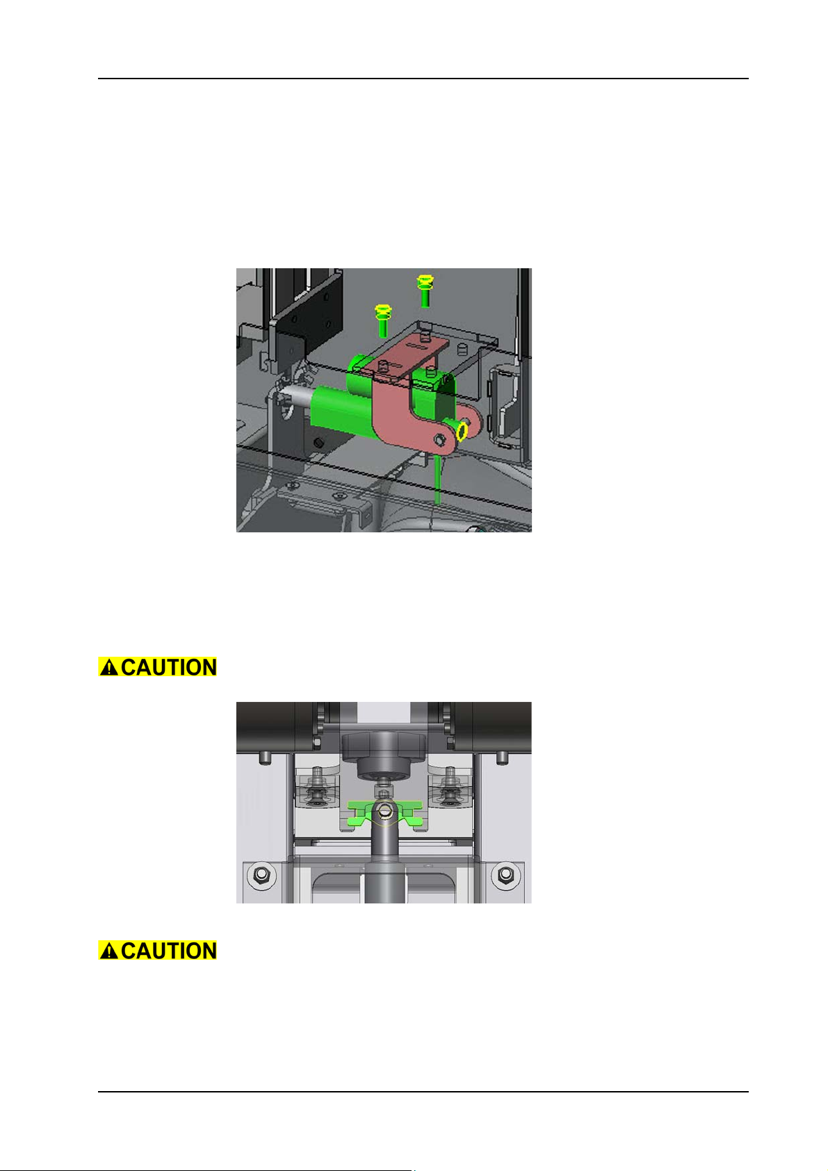
5.6.2 Mounting of squeegee linear drive
Picture 39: Squeegee lifting motor
• Position the linear drive onto the holder and mount the bolt and
circlip.
• Position the squeegee linear drive together with the linear drive
holder.
Take care not to position the motor wrongly. Refer to upper picture.
05.36.15 squeegee lowering mechanism - linear drive - XP_M_R_V1.00.fm
Picture 40: Articulation position
Make sure that the articulation is positioned correctly. Refer to upper
picture.
• Mount the two screws onto the chassis.
• Thread in the cable and connect it.
• Complete assembling according to the chapter MOUNTING OF
BRUSH UNIT LINEAR DRIVE.
28. November 2014 Edition: V1.00/2014 5-30
Copyright © 2014, Diversey Care
Page 54
GTS Technical Manual
5.6 Squeegee lowering mechanism
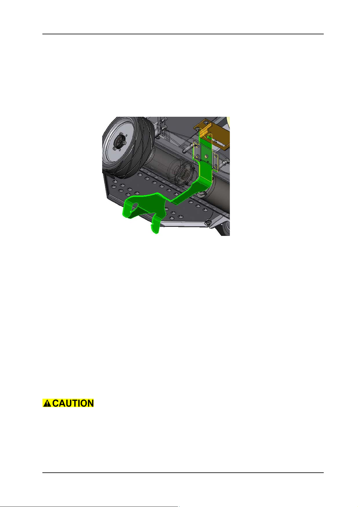
5.6.3 Removing of swinging arm
05.36.16 squeegee lowering mechanism - swinging arm - XP_M_R_V1.00.fm
Picture 41: Swinging arm
• Remove the squeegee from the swinging arm.
• Remove the brush unit according to the chapter REMOVING OF
COMPLETE BRUSH UNIT.
• Remove the brush unit linear drive according to the chapter
REMOVING OF BRUSH UNIT LINEAR DRIVE.
• Remove the squeegee linear drive according to the chapter
REMOVING OF SQUEEGEE LINEAR DRIVE.
Remarks
For an easier access lay the machine on the RH or LH side.
• Remove the two nuts (04/169) and washers (04/168) from the
bolts (06/165).
• Remove the two bolts from the chassis frame (04/110) and step
board (04/145).
• Loosen the two screws (06/107) from the holder (06/106) on
one side.
Take care that you release both screws at the same time.
• Loosen the two screws (06/107) on the other side.
Remarks
It is not necessary to remove the 4 screws (06/107) completely.
28. November 2014 Edition: V1.00/2014 5-31
Copyright © 2014, Diversey Care
Page 55
GTS Technical Manual
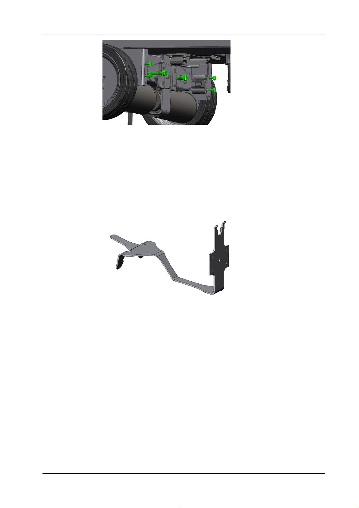
Picture 42: Flat spring screws
• Remove the flat spring (06/104).
• Remove the swinging arm (06/126) by weaving it out.
• According to what you need to exchange, remove the existing
parts from the swinging arm and place it on the new one.
Service
If you replace the handle ball (06/127) or the two plates (06/128), fix
the screws (06/101) and (06/139) with adhesive locking (06/162).
05.36.16 squeegee lowering mechanism - swinging arm - XP_M_R_V1.00.fm
Picture 43: Swinging arm detail
28. November 2014 Edition: V1.00/2014 5-32
Copyright © 2014, Diversey Care
Page 56
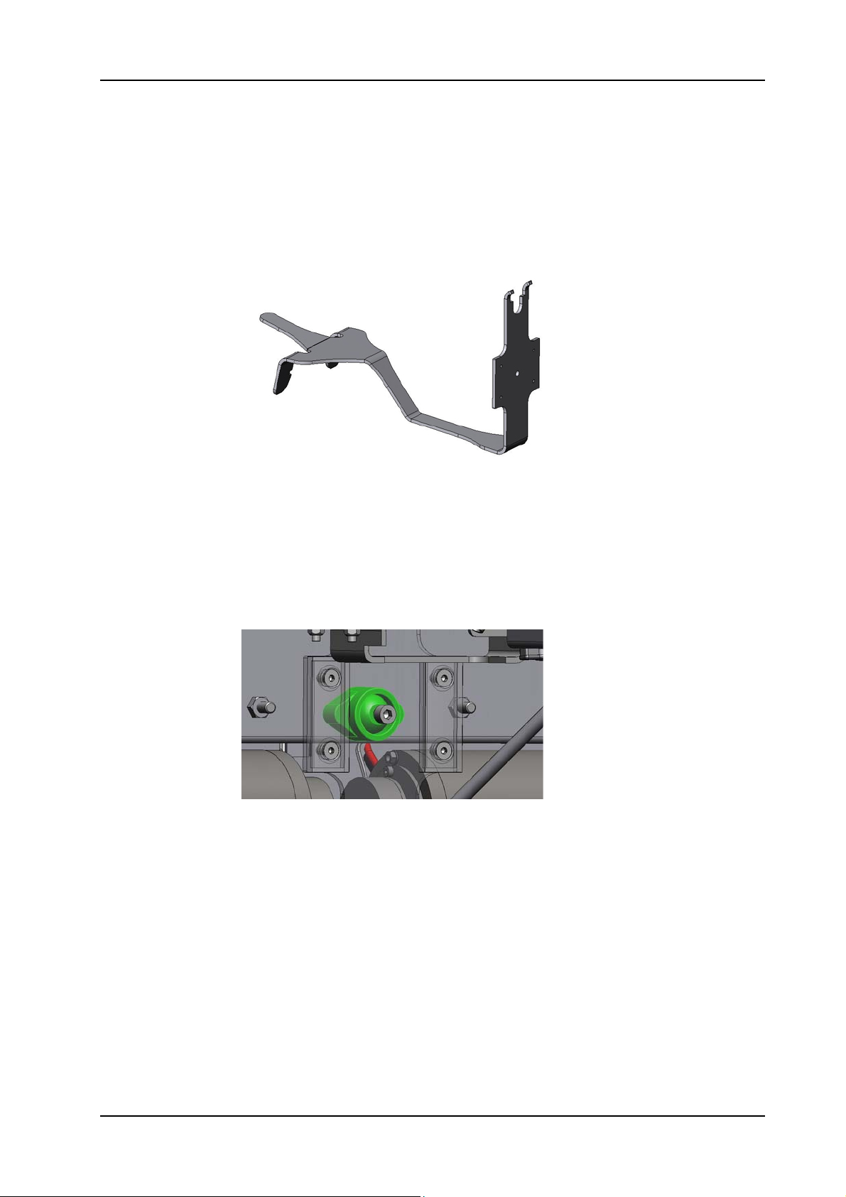
GTS Technical Manual
5.6 Squeegee lowering mechanism
5.6.4 Mounting of swinging arm
Picture 44: Swinging arm detail
05.36.16 squeegee lowering mechanism - swinging arm - XP_M_R_V1.00.fm
•Mount the swinging arm.
Service
Lubricate the handle ball (06/127) and ball socket (06/129) with wear
resistance spray (06/163).
Picture 45: Handle ball
28. November 2014 Edition: V1.00/2014 5-33
Copyright © 2014, Diversey Care
Page 57
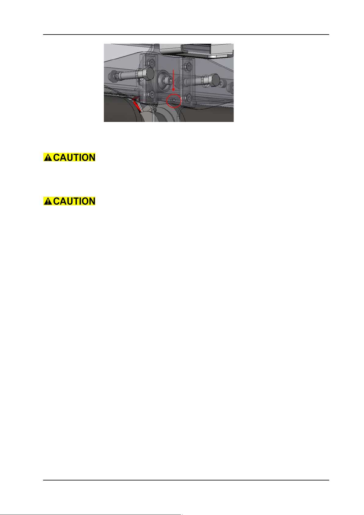
GTS Technical Manual
Picture 46: Flat spring position
• Mount the flat spring.
Take care that you position the flat spring correctly, so that the small
hole is on the bottom side. Refer to the upper picture.
• Tighten the 4 screws.
05.36.16 squeegee lowering mechanism - swinging arm - XP_M_R_V1.00.fm
Take care that you tighten both screws on one side at the same time.
• Mount the two bolts on the chassis frame and step board.
• Mount the two washers and nuts on the bolts.
• Lift up the machine.
• Mount the squeegee linear drive according to the chapter
MOUNTING OF SQUEEGEE LINEAR DRIVE.
• Mount the brush unit linear drive according to the chapter
MOUNTING OF BRUSH UNIT LINEAR DRIVE.
• Mount the brush unit according to the chapter MOUNTING OF
COMPLETE BRUSH UNIT.
• Mount the squeegee onto the swinging arm.
28. November 2014 Edition: V1.00/2014 5-34
Copyright © 2014, Diversey Care
Page 58
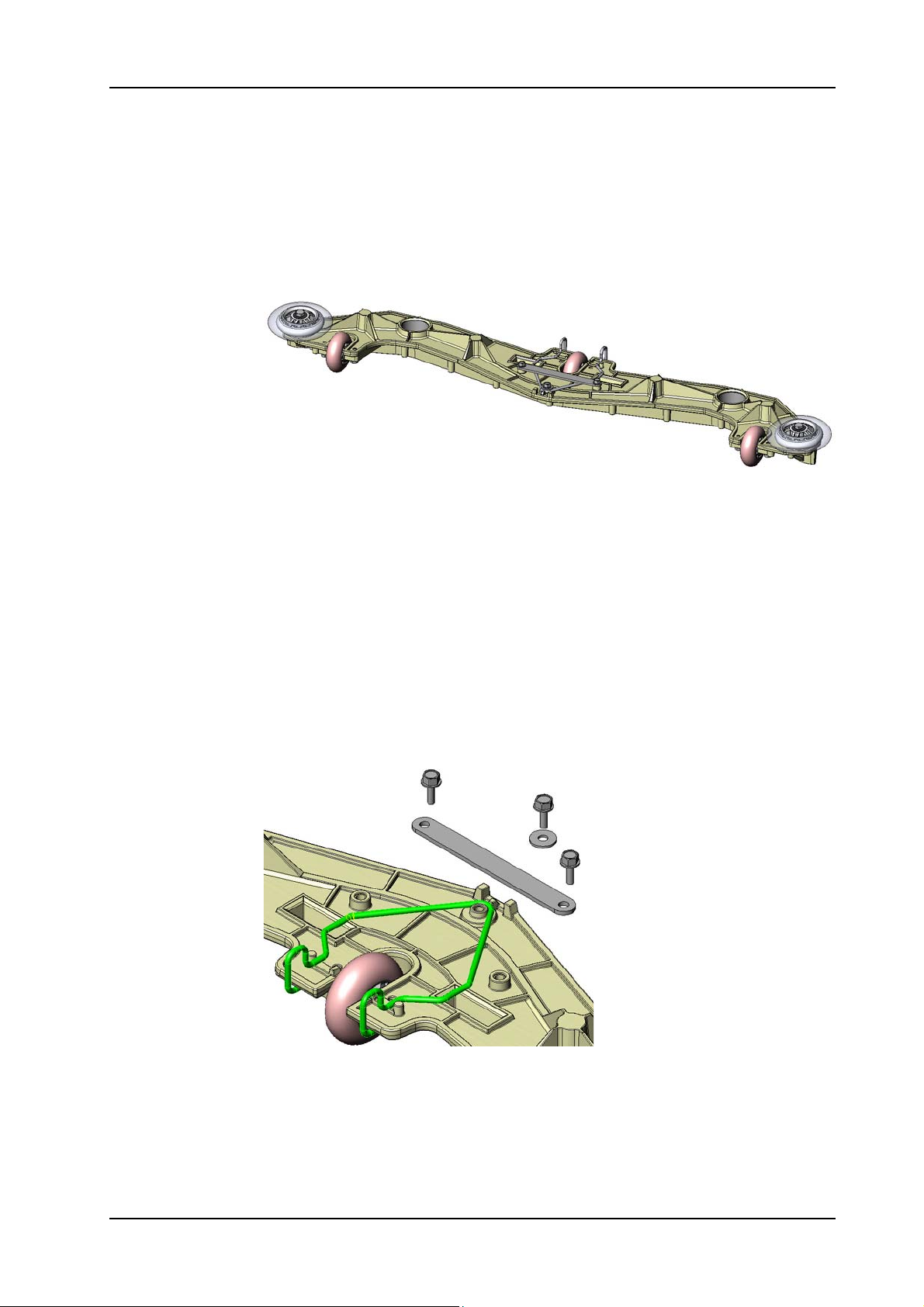
GTS Technical Manual
5.7 Squeegee 1650/XP/XP-M/XP-R
5.7.1 Removing of wire spring
Picture 47: Squeegee without flat spring
• Remove the self threading screw (1650:03/115, XP:06/115, XPM/R:07/115).
• According to which type of squeegee you have you need to
remove:
• the washer (1650:03/118)
• the flat spring (1650:03/106, XP:06/106, XP-M/R:07/
106).
05.40.30 squeegee - wire spring - 1650_XP_XP_M_R_V1.10.fm
Remarks
Detailed information to the spring you find at the end of the mounting
section.
Picture 48: Wire spring without flat spring
• Remove the two screws (1650:03/115, XP:06/115, XP-M/R:07/
115)
• Remove the shackle (1650:03/120, XP:06/125, XP-M/R: 07/
125).
• Remove the wire spring (1650:03/107, XP:06/107, XP-M/R:07/
107).
28. November 2014 Edition: V1.00/2014 5-35
Copyright © 2014, Diversey Care
Page 59
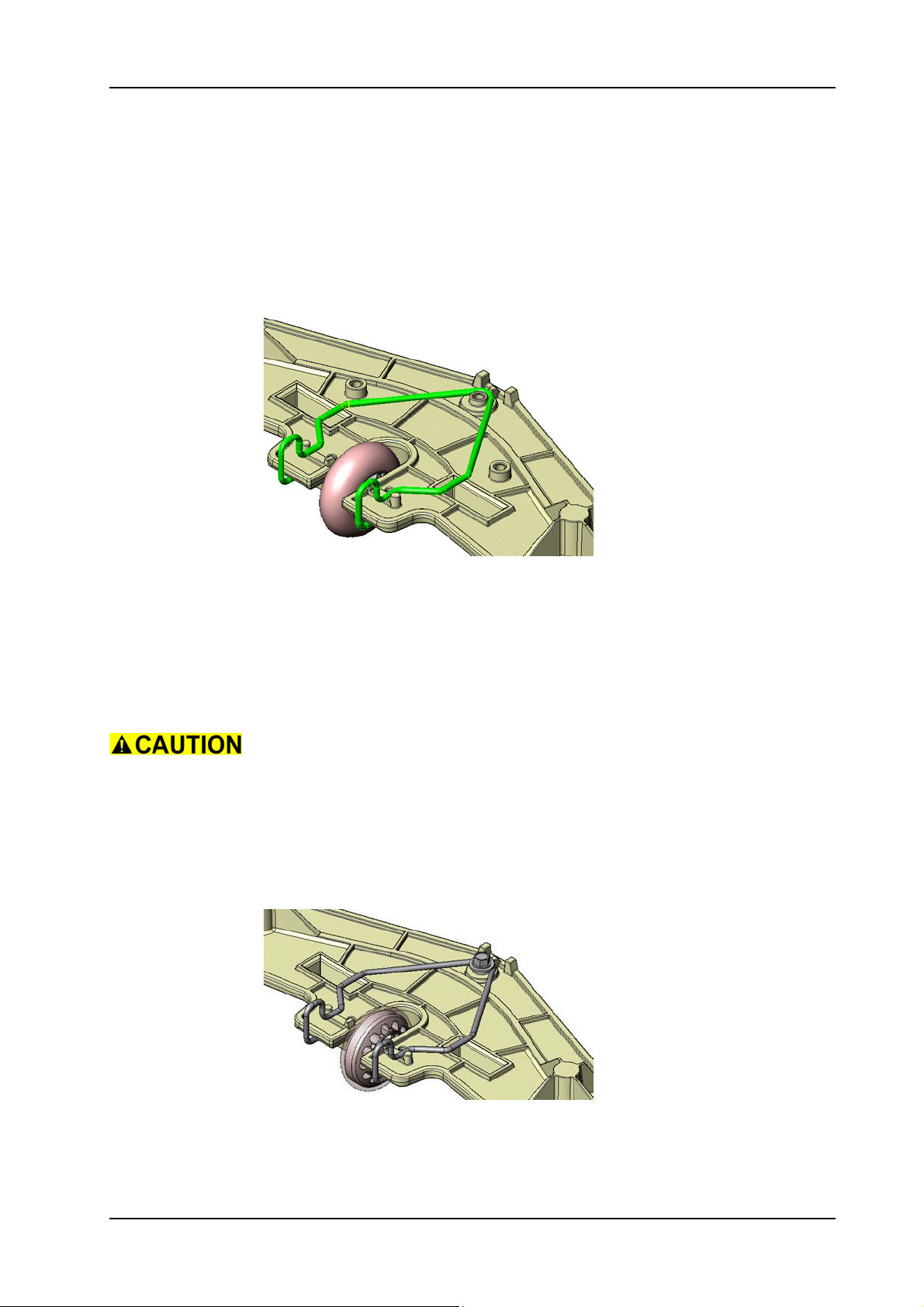
GTS Technical Manual
5.7 Squeegee 1650/XP/XP-M/XP-R
5.7.2 Mounting of wire spring
05.40.30 squeegee - wire spring - 1650_XP_XP_M_R_V1.10.fm
Picture 49: Wire spring mount
• Assemble the new wire spring.
Remarks
Please hook in the back part of the wire spring and place it inside the
moving way slots.
The squeegees of the TASKI swingo 1650 and XP are different. Please
take note of this as the pick up result can be affected.
Remarks
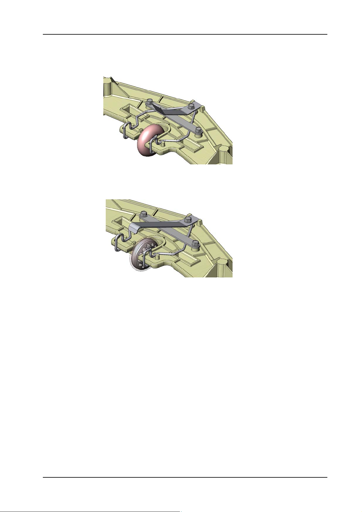
The TASKI swingo 1650 squeegee with old squeegee lowering
mechanism is in the following picture:
Picture 50: Wire spring 1650 old
28. November 2014 Edition: V1.00/2014 5-36
Copyright © 2014, Diversey Care
Page 60
GTS Technical Manual
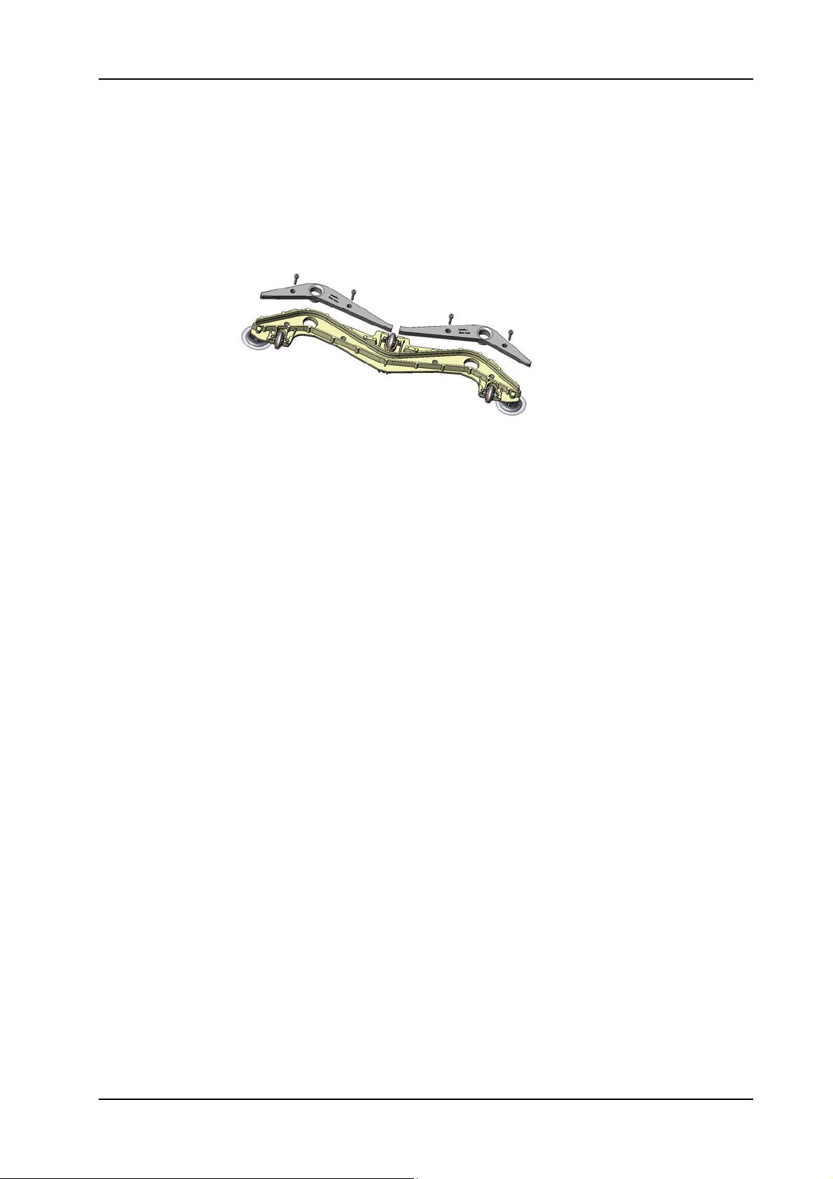
The TASKI swingo 1650 squeegee with new squeegee lowering
mechanism is in the following picture:
Picture 51: Wire spring 1650 new
The TASKI swingo XP/XP-M/XP-R squeegee is in the following picture:
05.40.30 squeegee - wire spring - 1650_XP_XP_M_R_V1.10.fm
Picture 52: Wire spring XP and XP-M/R
28. November 2014 Edition: V1.00/2014 5-37
Copyright © 2014, Diversey Care
Page 61
GTS Technical Manual
5.7 Squeegee
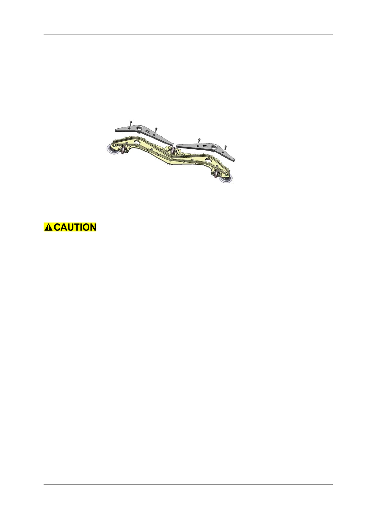
5.7.3 Removing of front and back blades
Picture 53: Squeegee blades
• Remove the 4 screws (1650:03/116, XP:06/116, XP-M/R:07/
116) from the blade clamping insert.
• Remove the LH (1650:03/113, XP:06/113, XP-M/R:07/113) and
the RH (1650:03/114, XP:06/114, XP-M/R:07/114) blade
clamping insert.
• Remove the front (1650:03/110, XP:06/110, XP-M/R:07/110)
and/or the back blade (1650:03/111, XP:06/111, XP-M/R:07/
111).
05.40.31 squeegee - front and back blades - 1650_XP_XP_M_R_V1.10.fm
28. November 2014 Edition: V1.00/2014 5-38
Copyright © 2014, Diversey Care
Page 62
GTS Technical Manual
5.7 Squeegee
5.7.4 Mounting of front and back blades
Picture 54: Squeegee blades
• Insert the new blades into the squeegee body (1650:03/105,
XP:06/105, XP-M/R:07/105).
05.40.31 squeegee - front and back blades - 1650_XP_XP_M_R_V1.10.fm
Ensure that the middle marking of the blades are placed in the middle
of the squeegee body.
Ensure that the 4 pressure springs (1650:03/112, XP:06/112, XP-M/
R:07/112) are placed nicely in the inlet of the squeegee body.
Ensure that the front and back blades are nicely fitted into the
squeegee body before inserting the blade clamping inserts.
• Place the LH and the RH blade clamping inserts into the
squeegee body.
• Insert the 4 screws for the blade clamping inserts.
Service
Please use wear resistant spray (1650:03/117, XP:06/117, XP-M/
R:07/117) for the screws.
• Tighten the screws evenly so the blade clamping is not angled.
28. November 2014 Edition: V1.00/2014 5-39
Copyright © 2014, Diversey Care
Page 63
GTS Technical Manual
5.8 Tool lowering unit
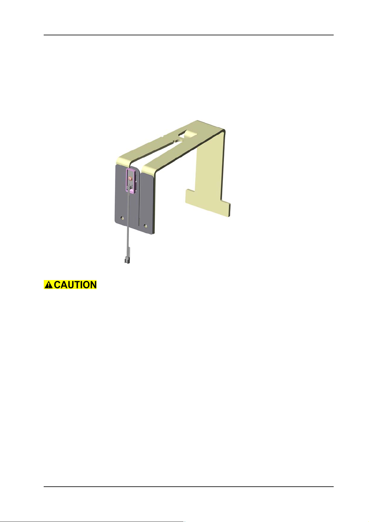
5.8.1 Removing of spring bracket set configured
05.64.18 tool lowering unit - spring bracket set configured - XP_M_R_V1.00.fm
Picture 55: Brush tension spring
Lower the brush unit before you start to disassemble. As soon as the
brush unit touches the floor, press the emergency stop.
• Disconnect the ribbon cable plug (08/166) of the sensor from
the spring bracket set according to the chapter REMOVING OF
POWER ELECTRONICS (refer to „Electrical“ section).
• Open tank set (03/104) by releasing the locking screw (12/119).
• Thread out the ribbon cable.
• Disconnect the plug of the brush (08/124) and the squeegee
linear drive (06/137).
28. November 2014 Edition: V1.00/2014 5-40
Copyright © 2014, Diversey Care
Page 64
GTS Technical Manual
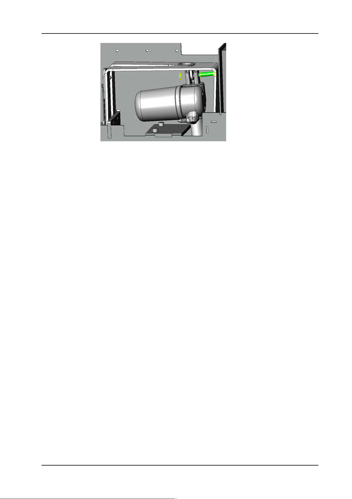
Picture 56: Bolt from brush tension spring
• Remove the circlip (08/130) from the upper bolt (08/131) of the
linear drive (08/124).
• Remove the upper bolt.
• Remove the two screws (08/121) for the spring bracket set
configured.
• Remove the spring bracket set configured (08/123).
05.64.18 tool lowering unit - spring bracket set configured - XP_M_R_V1.00.fm
28. November 2014 Edition: V1.00/2014 5-41
Copyright © 2014, Diversey Care
Page 65
GTS Technical Manual
5.8 Tool lowering unit
5.8.2 Mounting of spring bracket set configured
05.64.18 tool lowering unit - spring bracket set configured - XP_M_R_V1.00.fm
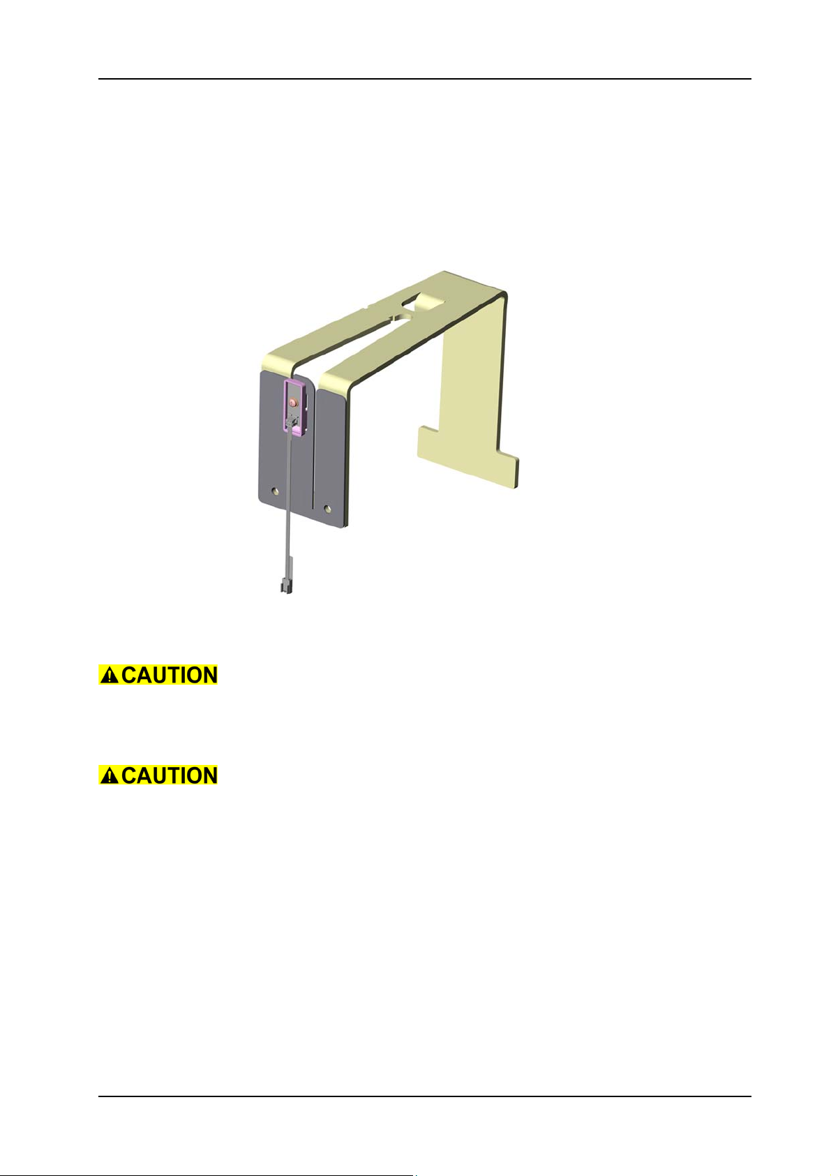
Picture 57: Brush tension spring
• Position the spring bracket set configured.
Always replace the complete spring bracket set configured. The
adjustment of the hall sensor can only be done in the factory.
• Mount the two screws for the spring bracket set configured.
Make sure that the tongue of the front plate moves freely.
• Mount the bolt of the linear drive.
Adjustment
Insert the bolt from the front side.
• Mount the circlip back on the bolt.
• Thread in the ribbon cable.
• Connect the plugs of the brush and squeegee linear drive.
• Close the tank set.
• Complete assembling of the plug according to the chapter
MOUNTING OF THE POWER ELECTRONICS.
28. November 2014 Edition: V1.00/2014 5-42
Copyright © 2014, Diversey Care
Page 66
GTS Technical Manual
5.8 Tool lowering unit
5.8.3 Removing of brush unit linear drive XP-M
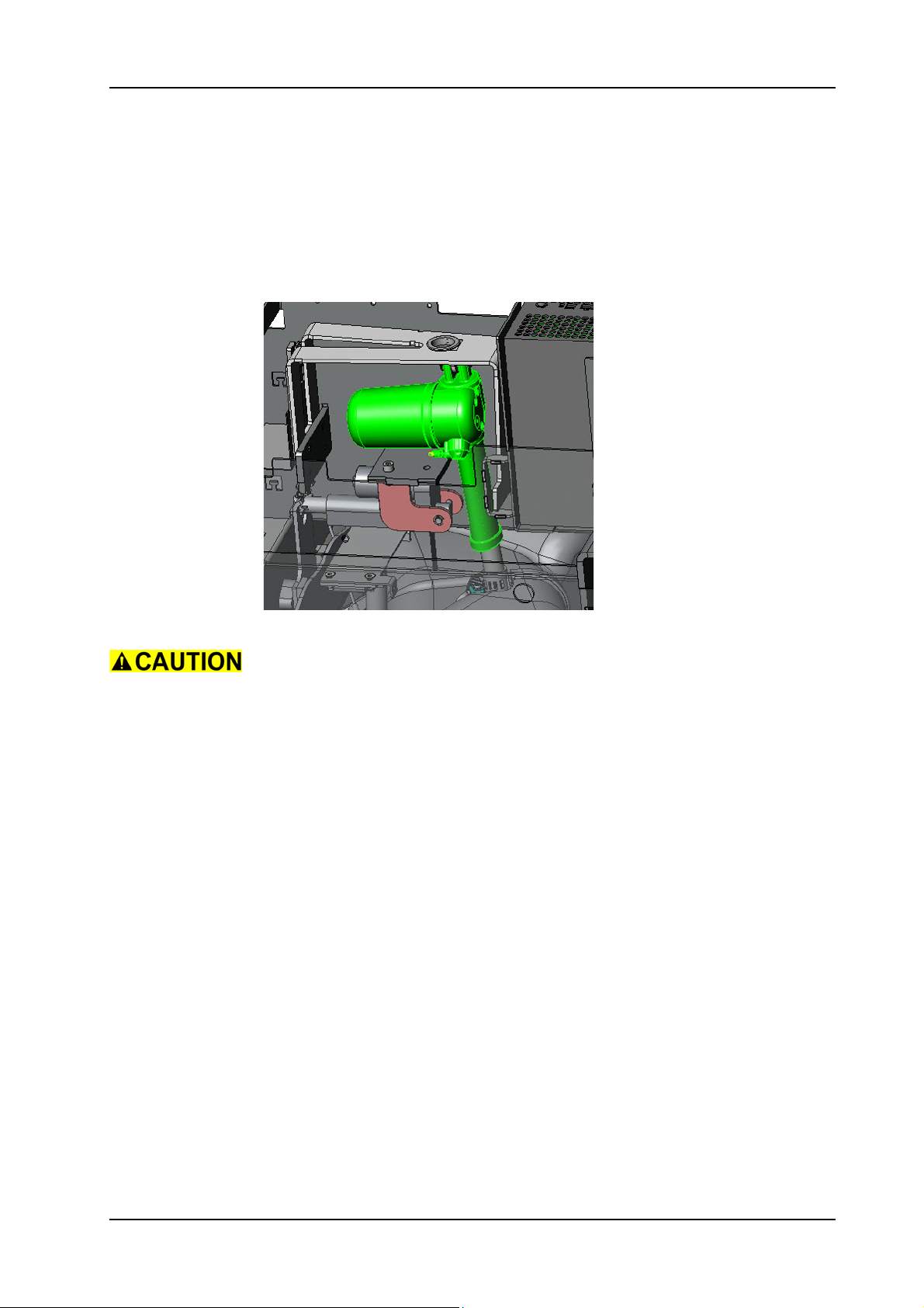
Picture 58: Brush unit linear drive XP-M
Lower the brush unit before you start to disassemble. As soon as the
brush unit touches the floor, press the emergency stop.
• Open tank set (03/104) by releasing locking screw (12/119).
• Remove the eight screws (09/110) for both brush housings (09/
111) and (09/128).
• Remove the two screws (09/112), wheels (09/113), bush (09/
155) and washers (09/109).
05.64.19 tool lowering unit - brush unit linear drive - XP_M_V1.00.fm
• Remove the two brush housings.
• Disconnect the plug of the brush unit linear drive (08/124) at the
top of the chassis (04/110) and thread out the cable.
• Remove the two circlips (08/130) from the upper and lower bolt
(08/131) of the brush unit linear drive (08/124).
• Remove the two bolts.
• Carefully weave out brush unit linear drive.
28. November 2014 Edition: V1.00/2014 5-43
Copyright © 2014, Diversey Care
Page 67
GTS Technical Manual
5.8 Tool lowering unit
5.8.4 Mounting of brush unit linear drive XP-M
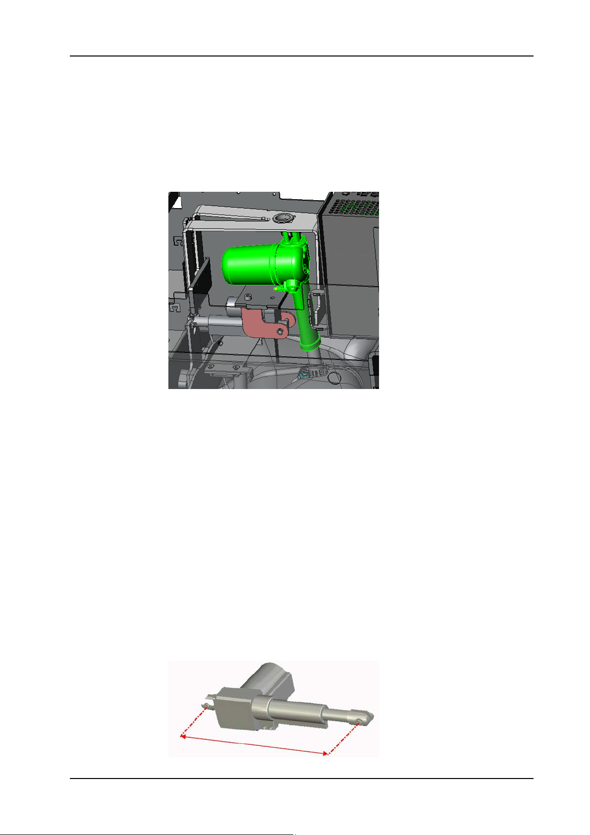
Picture 59: Brush unit linear drive XP-M
• Position the brush unit linear drive.
• Mount the two bolts.
Adjustment
Insert the bolt from the front side.
• Mount the two circlips back on the bolts.
• Thread in the cable and connect it.
05.64.19 tool lowering unit - brush unit linear drive - XP_M_V1.00.fm
• Mount the two brush housings.
• Mount the eight screws for both brush housings.
• Mount the two washers, bush, wheels and screws.
• Close the tank set.
Adjustment
Pre-adjust the brush unit linear drive to approximately 330 mm bolt
distance before assembling.
Picture 60: Brush unit linear drive pre-adjustment
28. November 2014 Edition: V1.00/2014 5-44
Copyright © 2014, Diversey Care
Page 68
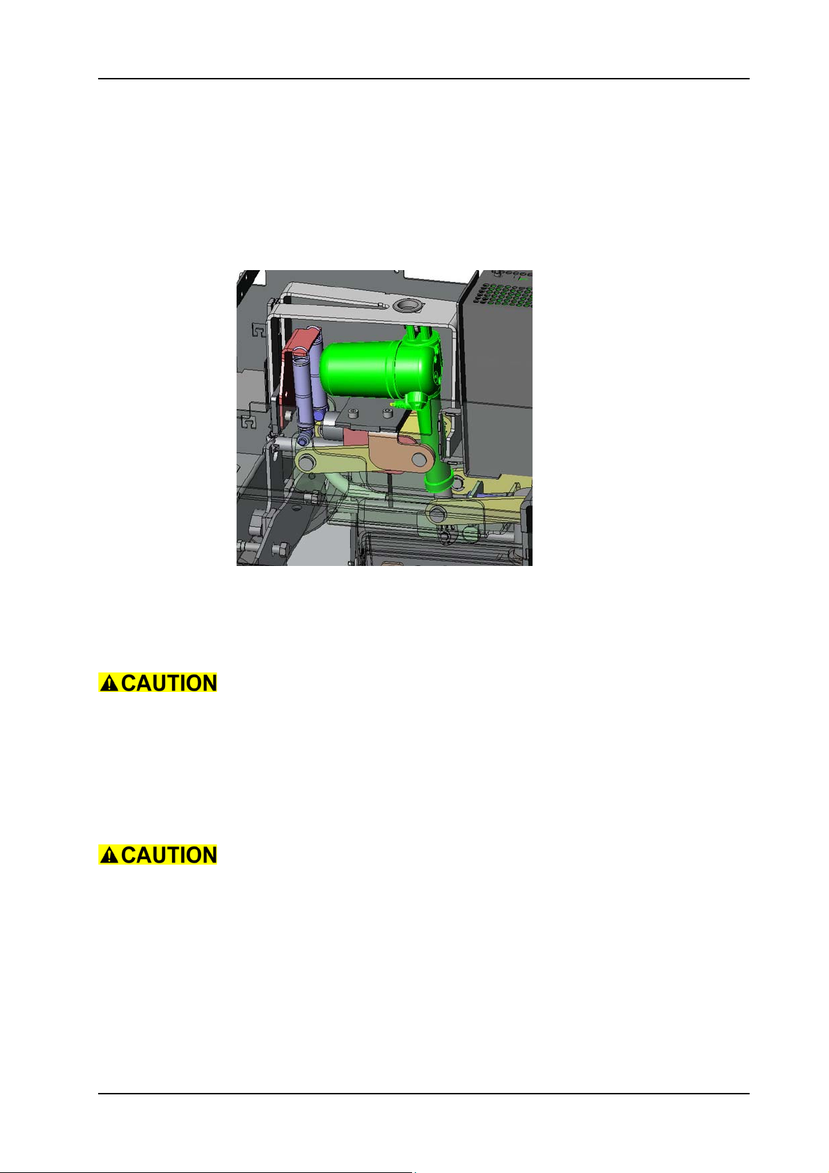
GTS Technical Manual
5.8 Tool lowering unit
5.8.5 Removing of brush unit linear drive XP-R
Picture 61: Brush unit linear drive XP-R
• Open tank set (03/104) by releasing locking screw (12/119).
• Remove the brush unit according to chapter REMOVING OF
COMPLETE BRUSH UNIT XP-R.
Lower the brush unit drive to the lowest position before you start to
disassemble. Press the emergency stop.
05.64.20 tool lowering unit - brush unit linear drive - XP_R_V1.00.fm
• Disconnect the brush unit linear drive (08/124) at the top of the
chassis and thread out the cable.
• Remove the two circlips (08/130) from the upper and lower bolt
(08/131) of the brush unit linear drive.
• Remove the two bolts.
Hold the brush support (08/111) as it is dropping as soon as you
remove the lower bolt of the linear drive.
• Carefully weave out brush unit linear drive.
28. November 2014 Edition: V1.00/2014 5-45
Copyright © 2014, Diversey Care
Page 69
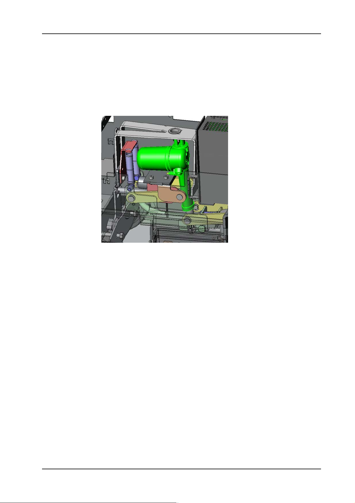
GTS Technical Manual
5.8 Tool lowering unit
5.8.6 Mounting of brush unit linear drive XP-R
Picture 62: Brush unit linear drive XP-R
• Position the brush unit linear drive.
• Mount the two bolts.
Adjustment
Insert the bolt from the front side.
05.64.20 tool lowering unit - brush unit linear drive - XP_R_V1.00.fm
• Mount the two circlips back on the bolts.
• Thread in the cable and connect it.
• Mount the brush unit according to chapter MOUNTING OF
COMPLETE BRUSH UNIT XP-R.
• Close the tank set.
28. November 2014 Edition: V1.00/2014 5-46
Copyright © 2014, Diversey Care
Page 70
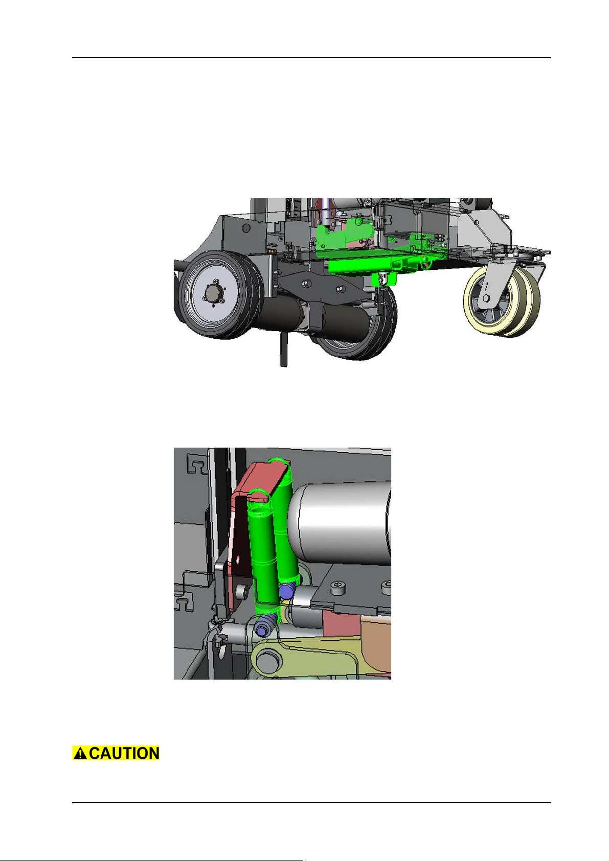
GTS Technical Manual
5.8 Tool lowering unit
5.8.7 Removing of tool lowering unit XP-R
05.64.21 tool lowering unit - tool lowering unit - XP_R_V1.00.fm
Picture 63: Tool lowering unit
• Open tank set (03/104) by releasing locking screw (12/119).
• Remove the brush unit according to chapter REMOVING OF
COMPLETE BRUSH UNIT XP-R.
• Remove the two springs (08/105) by releasing it at the top side.
Picture 64: Tension spring tool lowering unit
• Remove the brush unit linear drive according to chapter
REMOVING OF BRUSH UNIT LINEAR DRIVE XP-R.
Hold the brush support (08/111) as it is dropping as soon as you
remove the lower bolt of the linear drive.
28. November 2014 Edition: V1.00/2014 5-47
Copyright © 2014, Diversey Care
Page 71
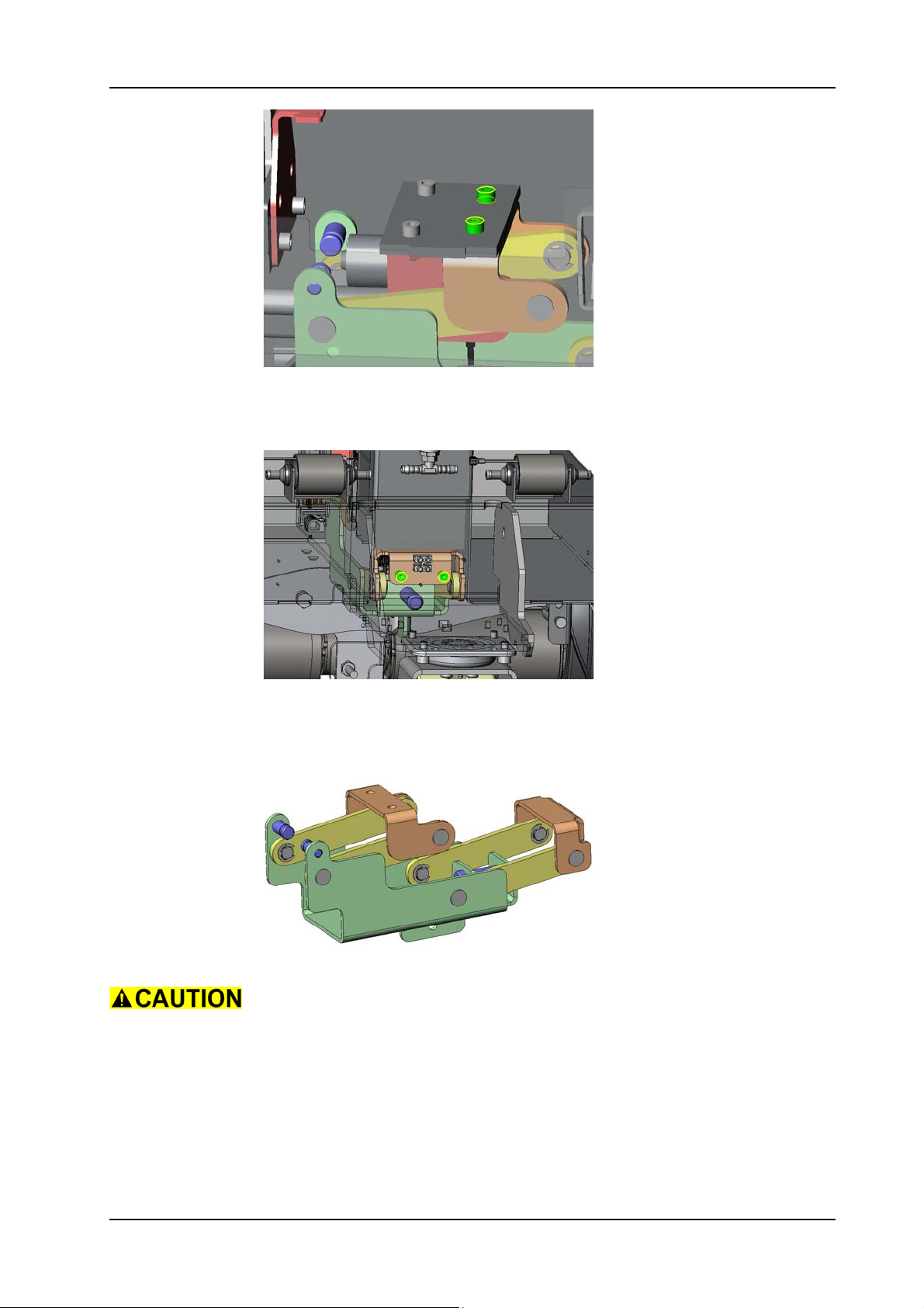
GTS Technical Manual
Picture 65: Tool lowering unit upper fixation
• Remove the screws (08/103) of the upper tool lowering holder
(08/104).
05.64.21 tool lowering unit - tool lowering unit - XP_R_V1.00.fm
Picture 66: Tool lowering unit front fixation
• Remove the two screws (08/103) of the front tool lowering
holder (08/108).
• Remove the complete tool lowering unit.
Picture 67: Tool lowering unit details
Be aware of the weight of the tool lowering unit.
28. November 2014 Edition: V1.00/2014 5-48
Copyright © 2014, Diversey Care
Page 72
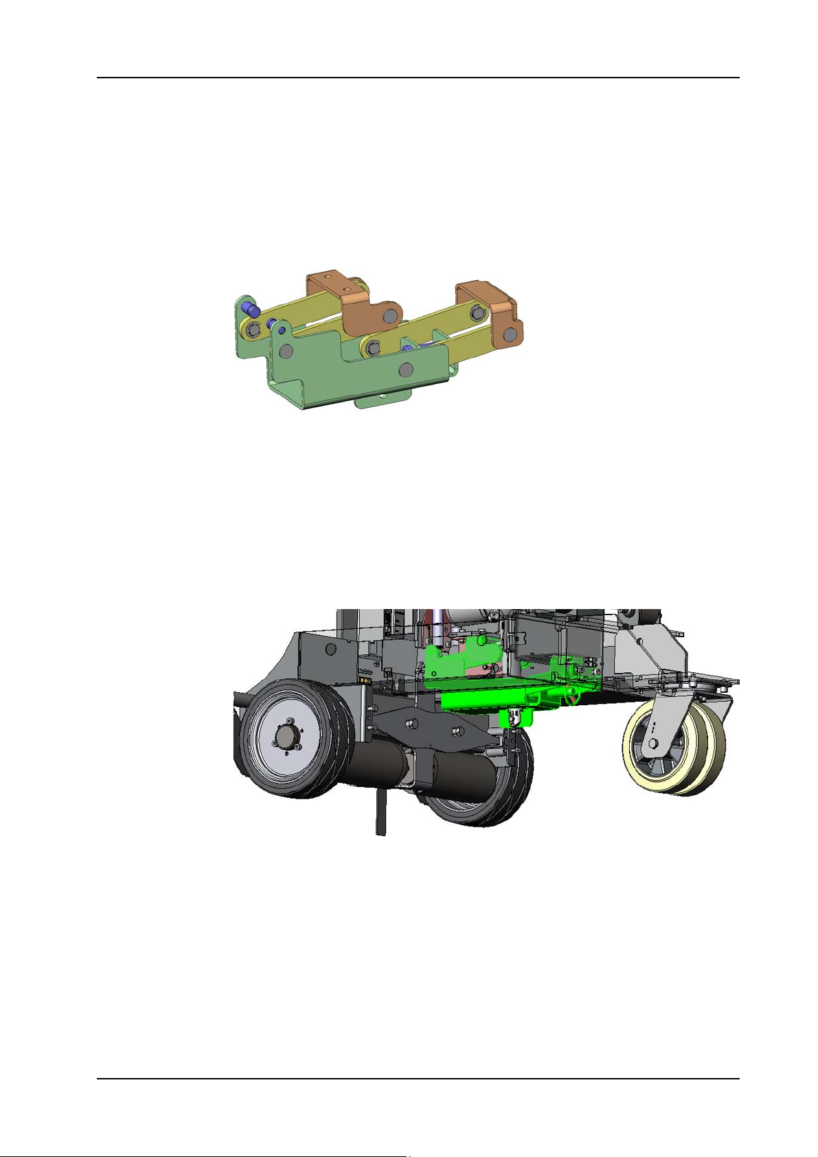
GTS Technical Manual
5.8 Tool lowering unit
5.8.8 Mounting of tool lowering unit XP-R
Picture 68: Tool lowering unit details
• Position the complete tool lowering unit into the machine
chassis.
• Mount the 4 screws of the front and upper tool lowering holder.
• Mount the brush unit linear drive according to chapter
MOUNTING OF BRUSH UNIT LINEAR DRIVE XP-R.
• Mount the two tension springs.
• Mount the brush unit according to chapter MOUNTING OF
COMPLETE BRUSH UNIT XP-R.
• Close the tank set.
05.64.21 tool lowering unit - tool lowering unit - XP_R_V1.00.fm
Picture 69: Tool lowering unit
28. November 2014 Edition: V1.00/2014 5-49
Copyright © 2014, Diversey Care
Page 73
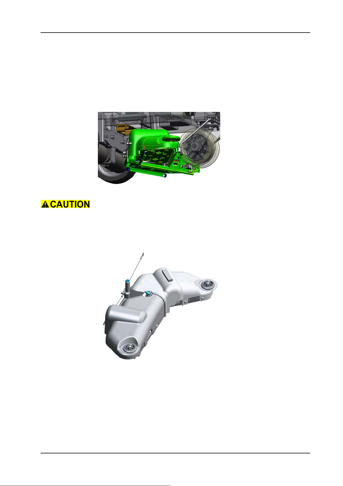
GTS Technical Manual
5.9 Brush drive
5.9.1 Removing of complete brush unit XP-M
Picture 70: Brush unit complete
05.66.17 brush drive - brush drive unit - XP_M_V1.00.fm
Lower the brush unit before you start to disassemble. As soon as the
brush unit touches the floor, press the emergency stop.
If possible, do not remove brushes/pads. If you remove the brushes/
pads the console might get damaged when lowering the brush unit.
Picture 71: Brush unit complete
• Open tank set (03/104) by releasing the locking screw (12/119).
• Disconnect the two brush motor plugs at the connection point at
the chassis (04/110).
• Remove the cable ties from the chassis and remove the brush
motor cable.
• Remove the eight screws (09/110) for both brush housings (09/
111) and (09/128).
• Remove the two screws (09/112), wheels (09/113), bush (09/
28. November 2014 Edition: V1.00/2014 5-50
Copyright © 2014, Diversey Care
Page 74
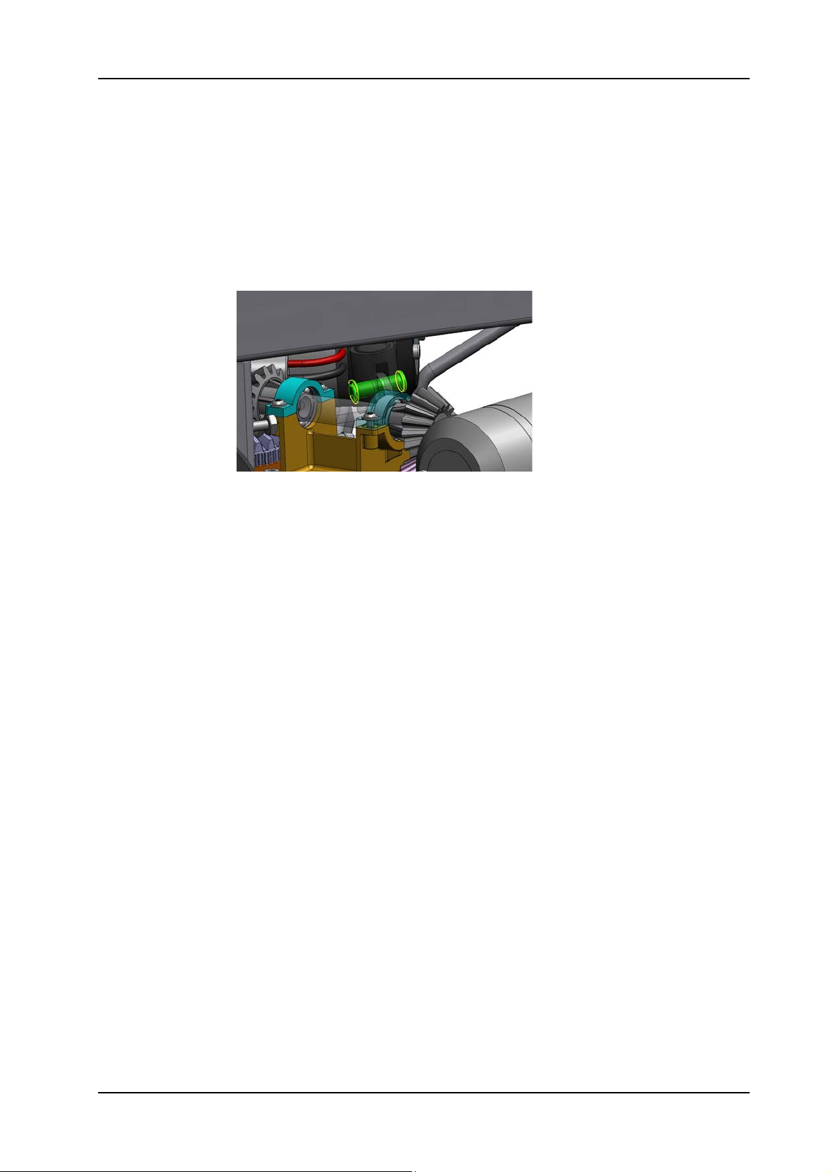
GTS Technical Manual
155) and washers (09/109).
• Remove the two brush housings.
• Remove the two screws (09/143) and nuts (09/115) on both
sides of the chassis frame (04/110) to release the steel rope (09/
140).
• Remove the two hose clamps (05/111) on the lower side of the
pumps (05/119).
• Remove the two water hose (05/121) and (05/122) on the lower
side of the pumps.
• Remove the four screws (09/133) for the bracket fixation (12/
112).
05.66.17 brush drive - brush drive unit - XP_M_V1.00.fm
Picture 72: Bolt with circlip
• Remove the circlip (08/130) at the side of the brush unit.
• Remove the bolt (08/131) at the side of the brush unit.
• Remove the two brush motor plugs at the connection point at the
chassis.
• Remove the complete brush unit.
28. November 2014 Edition: V1.00/2014 5-51
Copyright © 2014, Diversey Care
Page 75
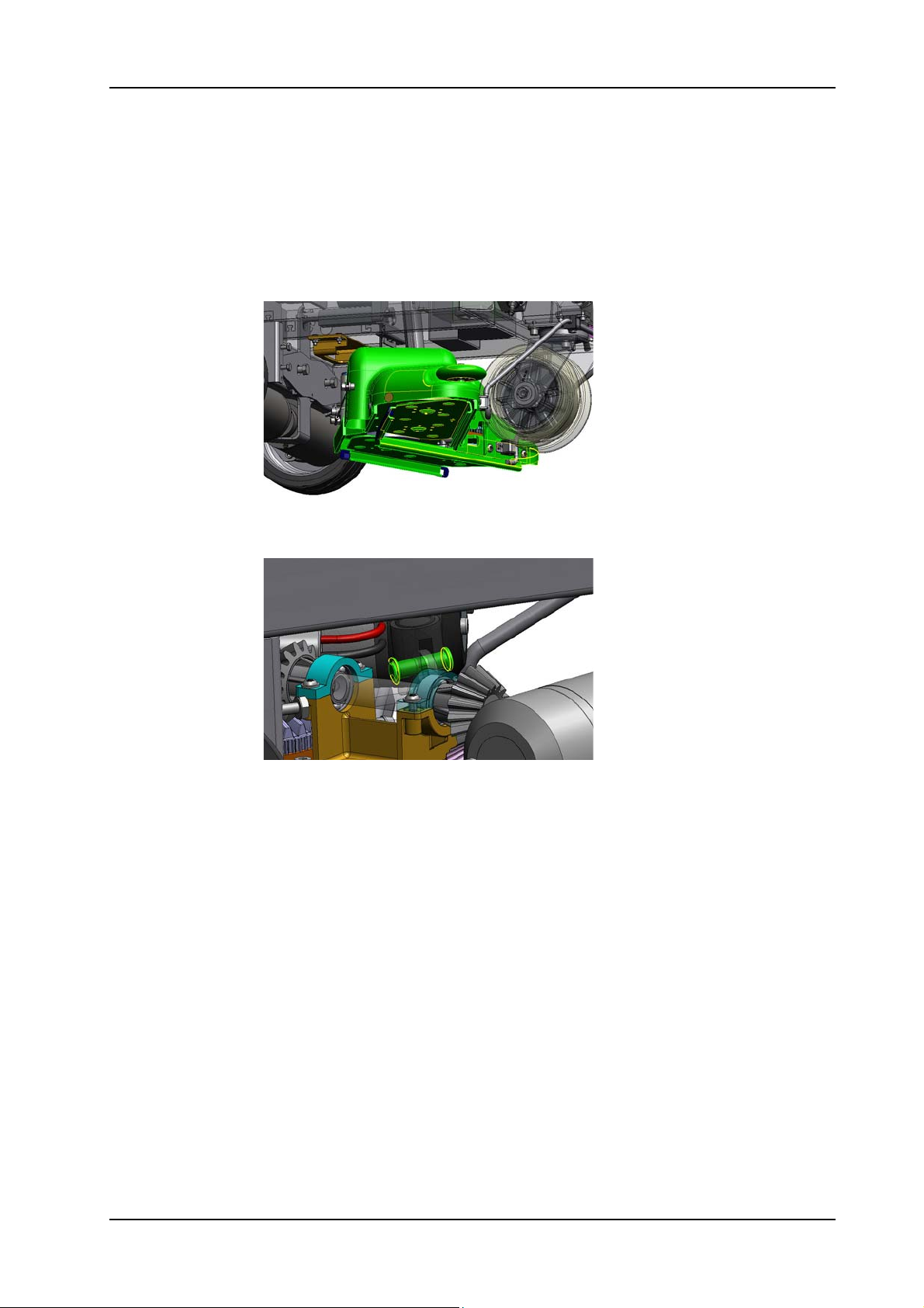
GTS Technical Manual
5.9 Brush drive
5.9.2 Mounting of complete brush unit XP-M
Picture 73: Brush unit complete
05.66.17 brush drive - brush drive unit - XP_M_V1.00.fm
• Position the brush unit under the machine.
Picture 74: Bolt with circlip
• Mount the bolt of the linear drive.
Adjustment
Insert the bolt from the front side.
• Mount the circlip on the bolt.
• Position the bracket fixation.
• Mount the four screws for the bracket fixation.
• Mount water hose on the pumps.
• Mount hose clamps on the pumps.
• Position the steel rope.
• Mount the two screws and nuts on both sides of the chassis
frame for the steel rope.
• Mount the two brush housings.
• Mount the eight screws for both brush housings.
• Mount the two washers, bush, wheels and screws.
• Connect the two brush motor plugs at the connection point at
the chassis.
• Place the cable on the chassis and mount the cable ties.
28. November 2014 Edition: V1.00/2014 5-52
Copyright © 2014, Diversey Care
Page 76
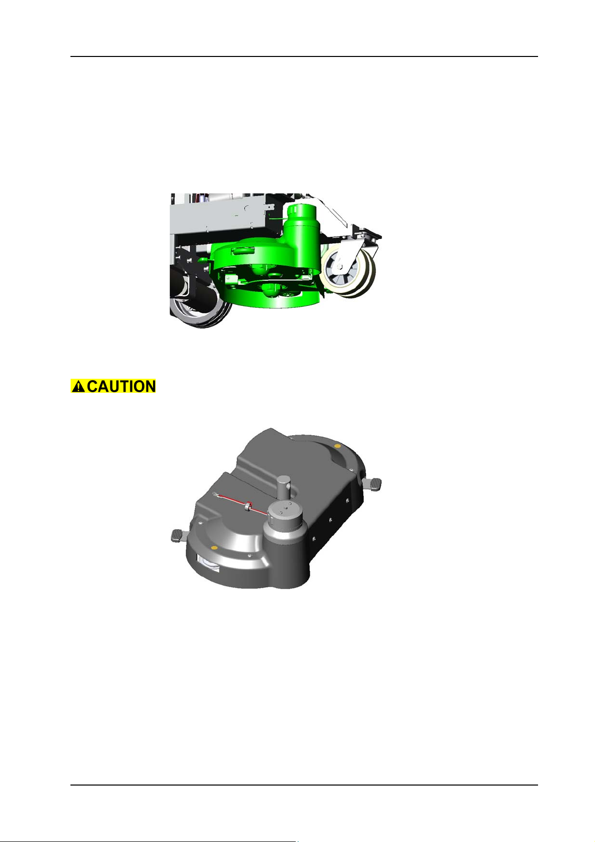
GTS Technical Manual
Before fixing the brush unit motor cables, please check that the cables
allow the complete movement of the brush unit.
• Close the tank set.
Adjustment
According to which type of machine you work on you need to place
the drive unit holder (09/157) on the correct position. See also the
spare parts list.
05.66.17 brush drive - brush drive unit - XP_M_V1.00.fm
Picture 75: Drive unit holder
28. November 2014 Edition: V1.00/2014 5-53
Copyright © 2014, Diversey Care
Page 77
GTS Technical Manual
5.9 Brush drive
5.9.3 Removing of complete brush unit XP-R
05.66.20 brush drive - brush drive unit - XP_R_V1.00.fm
Picture 76: Brush unit complete
• Remove the tools.
Lower the brush unit before you start to disassemble. As soon as the
brush unit touches the floor, press the emergency stop.
Picture 77: Brush unit
• Open tank set (03/104) by releasing the locking screw (12/119).
• Disconnect the brush motor plugs at the connection block (04/
111) at the chassis (04/110).
• Remove the two hose clamps (05/111) on the lower side of the
pumps (05/119).
• Remove the cable ties of the two water hose (11/149).
• Remove the two hoses on the lower side of the pumps.
• Remove the pin with ring (08/112).
28. November 2014 Edition: V1.00/2014 5-54
Copyright © 2014, Diversey Care
Page 78
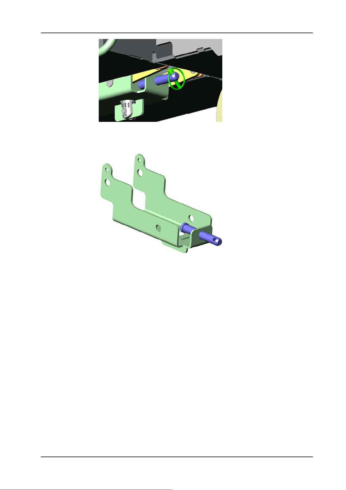
GTS Technical Manual
Picture 78: Pin with ring
• Remove the whole brush unit by pulling it off from the bolt of the
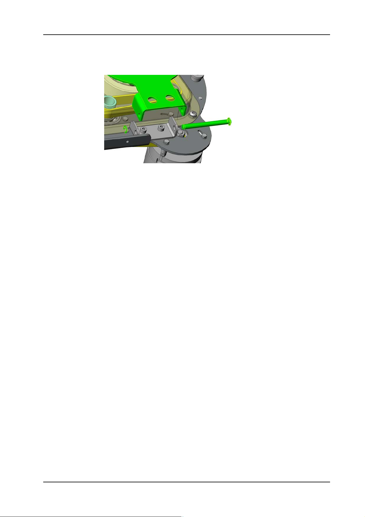
brush holding bracket (08/111).
05.66.20 brush drive - brush drive unit - XP_R_V1.00.fm
Picture 79: Brush holding bracket
• Release the stop actuator.
• Switch ON the machine so the brush unit goes into the upper
position.
• Slide out the brush unit to the RH side of the machine.
Remarks
If necessary move the castor wheel to the front position for more
space.
28. November 2014 Edition: V1.00/2014 5-55
Copyright © 2014, Diversey Care
Page 79
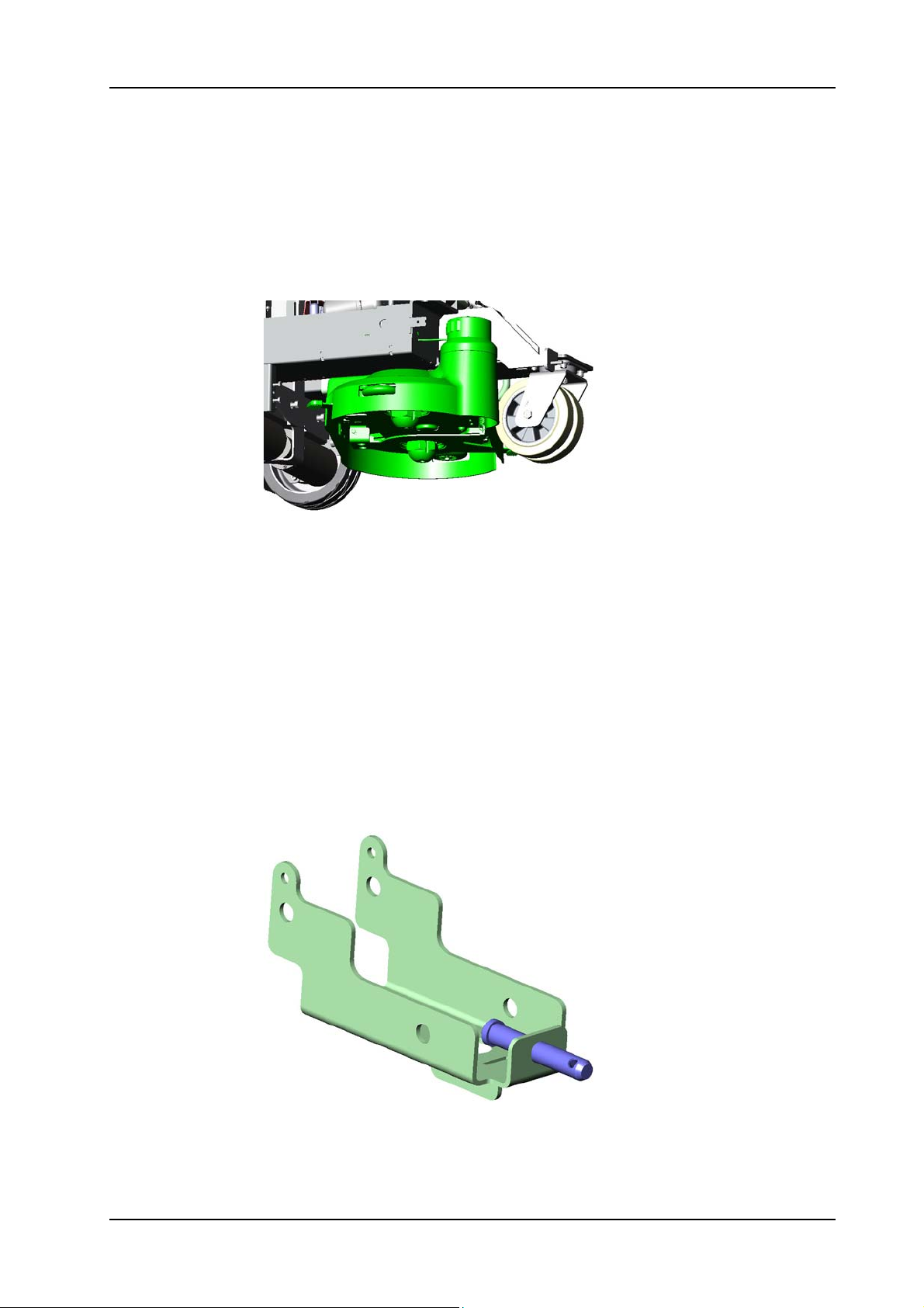
GTS Technical Manual
5.9 Brush drive
5.9.4 Mounting of complete brush unit XP-R
05.66.20 brush drive - brush drive unit - XP_R_V1.00.fm
Picture 80: Brush unit complete
• Slide in the brush unit from the RH side of the machine.
• Place the brush unit in the correct position so the brush holding
bracket is in line.
• Switch ON the machine and lower the brush unit.
Remarks
As soon as the brush lowering unit gets a resistance it stops.
Therefore you do not have much pressure on it and you still can move
the brush unit.
• Move the brush unit into the correct position.
• Place the hole of the flange bolt (10/105) onto the bolt of the
brush holding bracket.
Picture 81: Brush holding bracket
• Push the brush unit to the back side.
• Mount the pin with ring.
28. November 2014 Edition: V1.00/2014 5-56
Copyright © 2014, Diversey Care
Page 80
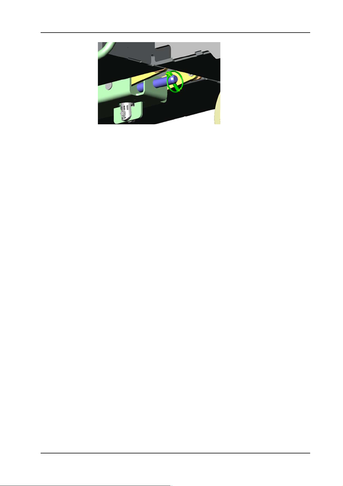
GTS Technical Manual
Picture 82: Pin with ring
• Mount two hoses and hose clamps on to the pump.
• Place all the cable ties onto the chassis.
• Connect the wires to the connection block.
• Close the tank set and tighten the locking screw.
05.66.20 brush drive - brush drive unit - XP_R_V1.00.fm
28. November 2014 Edition: V1.00/2014 5-57
Copyright © 2014, Diversey Care
Page 81
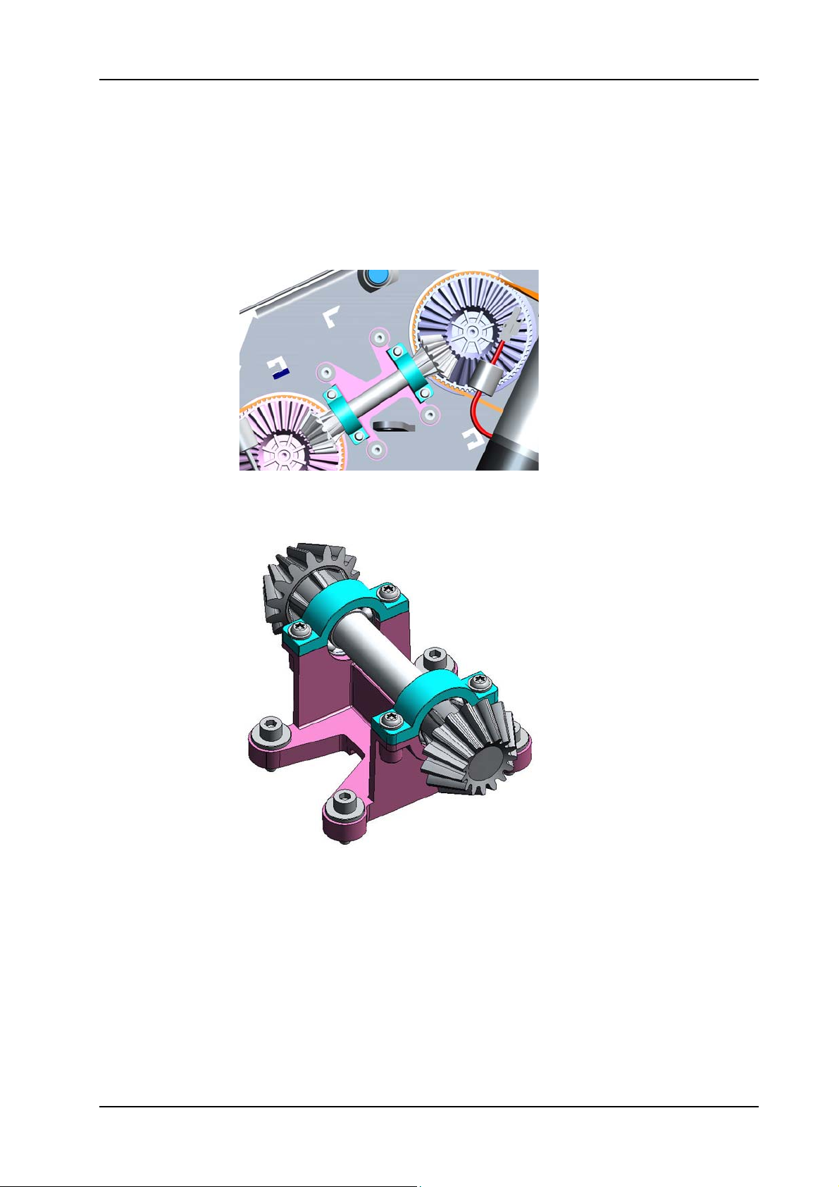
GTS Technical Manual
5.9 Brush drive
5.9.5 Removing of support with bearing (synchronisation) XP-M
05.68.83 brush drive - support with bearing - XP_M_V1.10.fm
Picture 83: Support with bearing (synchronisation)
• Remove the brush unit according to the chapter REMOVING OF
COMPLETE BRUSH UNIT XP-M.
Picture 84: Support with bearing detail
• Remove the four Allen screws for the support with bearing (09/
101).
• Remove the support with bearing.
28. November 2014 Edition: V1.00/2014 5-58
Copyright © 2014, Diversey Care
Page 82
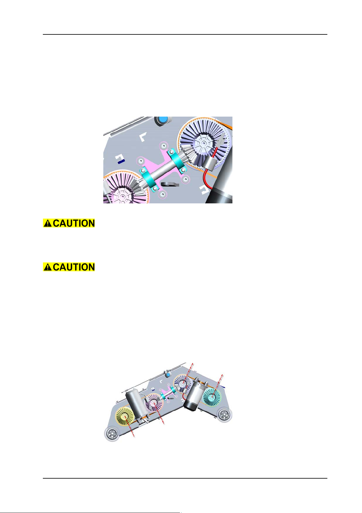
GTS Technical Manual
5.9 Brush drive XP-M
5.9.6 Mounting of support with bearing (synchronisation) XP-M
05.68.83 brush drive - support with bearing - XP_M_V1.10.fm
Picture 85: Support with bearing (synchronisation)
Take care that you clean the motor base plate (09/127) before you
position the synchronisation (09/101).
• Position the support with bearing.
Take care that you position the synchronisation correctly onto the
motor base plate (see upper picture).
• Mount the four screws for the support with bearing.
• Complete assembling the brush unit according to the chapter
MOUNTING OF COMPLETE BRUSH UNIT XP-M.
Adjustment
Position the bevel gears (09/121) such, that the arrows are positioned
on the marks on the base plate.
Picture 86: Position bevel gear
28. November 2014 Edition: V1.00/2014 5-59
Copyright © 2014, Diversey Care
Page 83
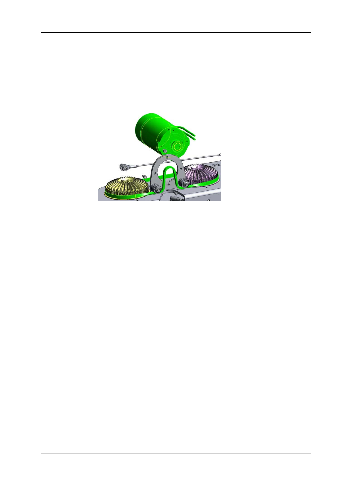
GTS Technical Manual
5.9 Brush drive
5.9.7 Removing of brush belt & brush motor XP-M
05.68.84 brush drive - brush belt & brush motor - XP_M_V1.00.fm
Picture 87: Brush belt & brush motor
• Remove the brush unit according to the chapter REMOVING OF
COMPLETE BRUSH UNIT XP-M.
• Remove the synchronisation according to the chapter REMOVING
OF SUPPORT WITH BEARING (SYNCHRONISATION) XP-M.
• Untighten the screws (09/107) with the ball bearings (09/108)
to release tension of brush belt (09/120).
• Remove the four screws (09/114) of the brush motor (09/116).
• Remove brush motor.
• Remove brush belt.
28. November 2014 Edition: V1.00/2014 5-60
Copyright © 2014, Diversey Care
Page 84
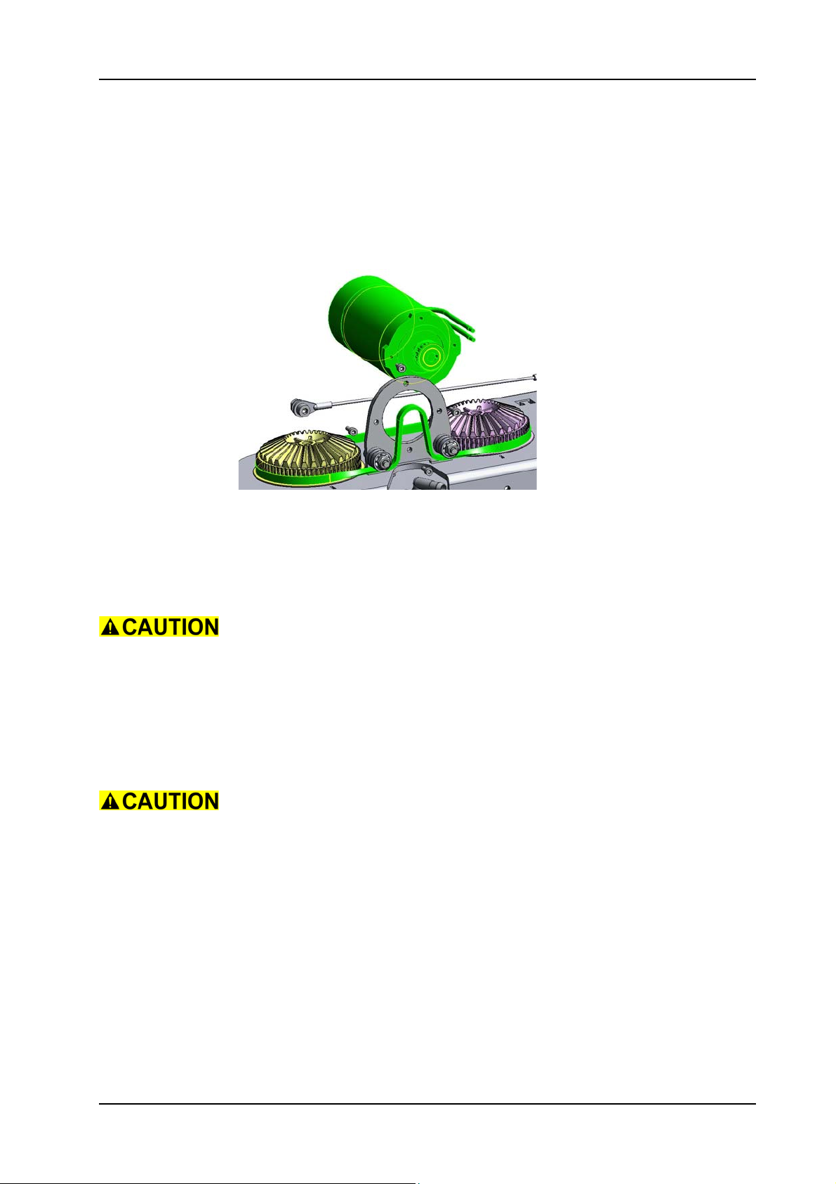
GTS Technical Manual
5.9 Brush drive
5.9.8 Mounting of brush belt & brush motor XP-M
05.68.84 brush drive - brush belt & brush motor - XP_M_V1.00.fm
Picture 88: Brush belt & brush motor
• Mount brush belt.
• Position brush motor.
• Mount the four screws of the brush motor.
• Tighten the screws to tension the brush belt.
Do not tension the belts (09/120) too much. Both belts need to have
the same tension.
• Complete assembling the synchronisation according to the
chapter MOUNTING OF SUPPORT WITH BEARING
(SYNCHRONISATION) XP-M.
• Complete assembling the brush unit according to the chapter
MOUNTING OF COMPLETE BRUSH UNIT XP-M.
If the brush motor has to be replaced check the polarisation. The
motors have to rotate in opposite directions (both brushes have to
turn to the inner side).
Service
Fix the screws (09/114) of the brush motor with adhesive locking (09/
160).
28. November 2014 Edition: V1.00/2014 5-61
Copyright © 2014, Diversey Care
Page 85
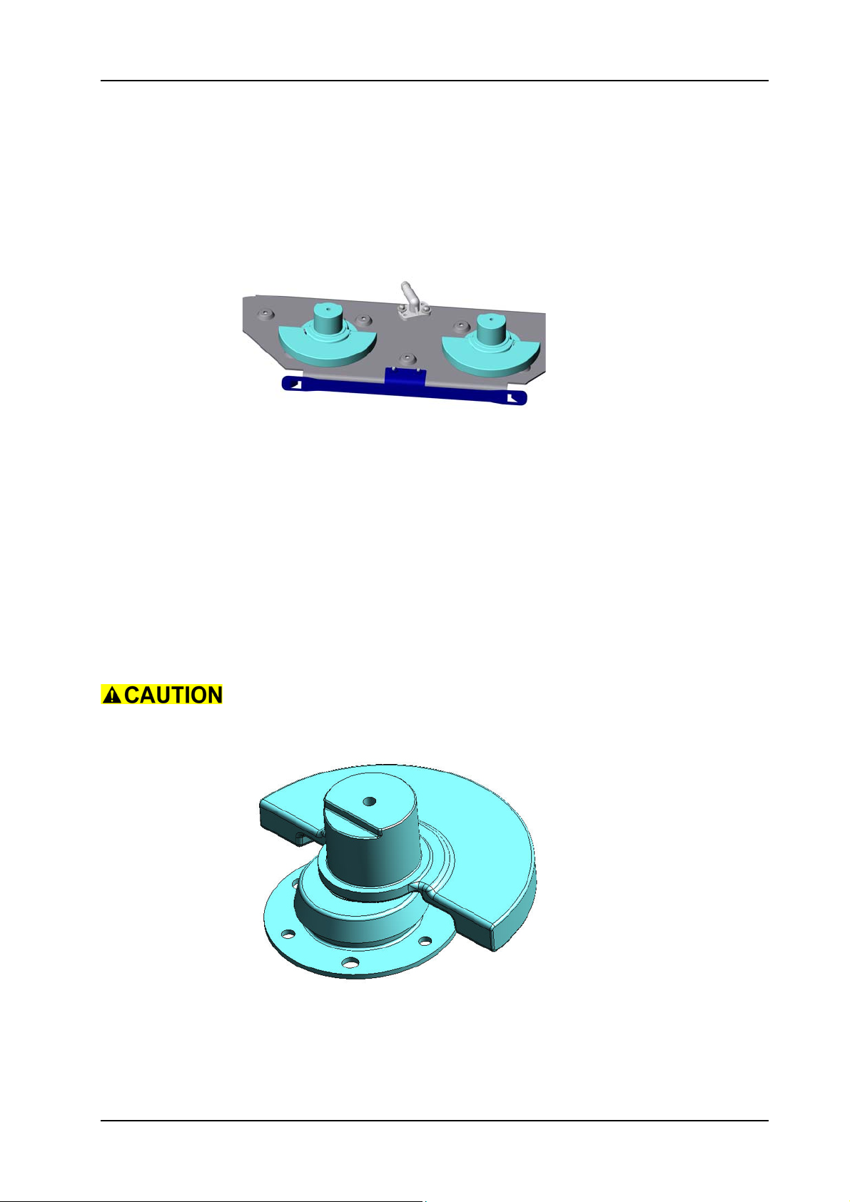
GTS Technical Manual
5.9 Brush drive
5.9.9 Removing of eccentric shaft XP-M
Picture 89: Eccentric shaft
• Remove the brush unit according to the chapter REMOVING OF
COMPLETE BRUSH UNIT XP-M.
• Remove the synchronisation according to the chapter REMOVING
OF SUPPORT WITH BEARING (SYNCHRONISATION) XP-M.
• Remove the brush belt according to the chapter REMOVING OF
BRUSH BELT & BRUSH MOTOR XP-M.
• Remove the two hose clamps (05/111) on the brush drive end.
• Remove the hoses (05/121) and (05/122).
• Remove the screws (09/104) together with the washers (09/118)
and the bevel gears (09/121).
• Turn the brush unit upside down.
• Carefully remove brush console (09/138).
If the eccentric shaft is rusty use a plastic hammer. Take care when
removing the brush console that it does not tilt.
05.68.85 brush drive - eccentric shaft - XP_M_V1.00.fm
Picture 90: Eccentric shaft detail
• Remove the three self-locking nuts M6 (09/125).
• Remove eccentric shaft (09/124).
28. November 2014 Edition: V1.00/2014 5-62
Copyright © 2014, Diversey Care
Page 86
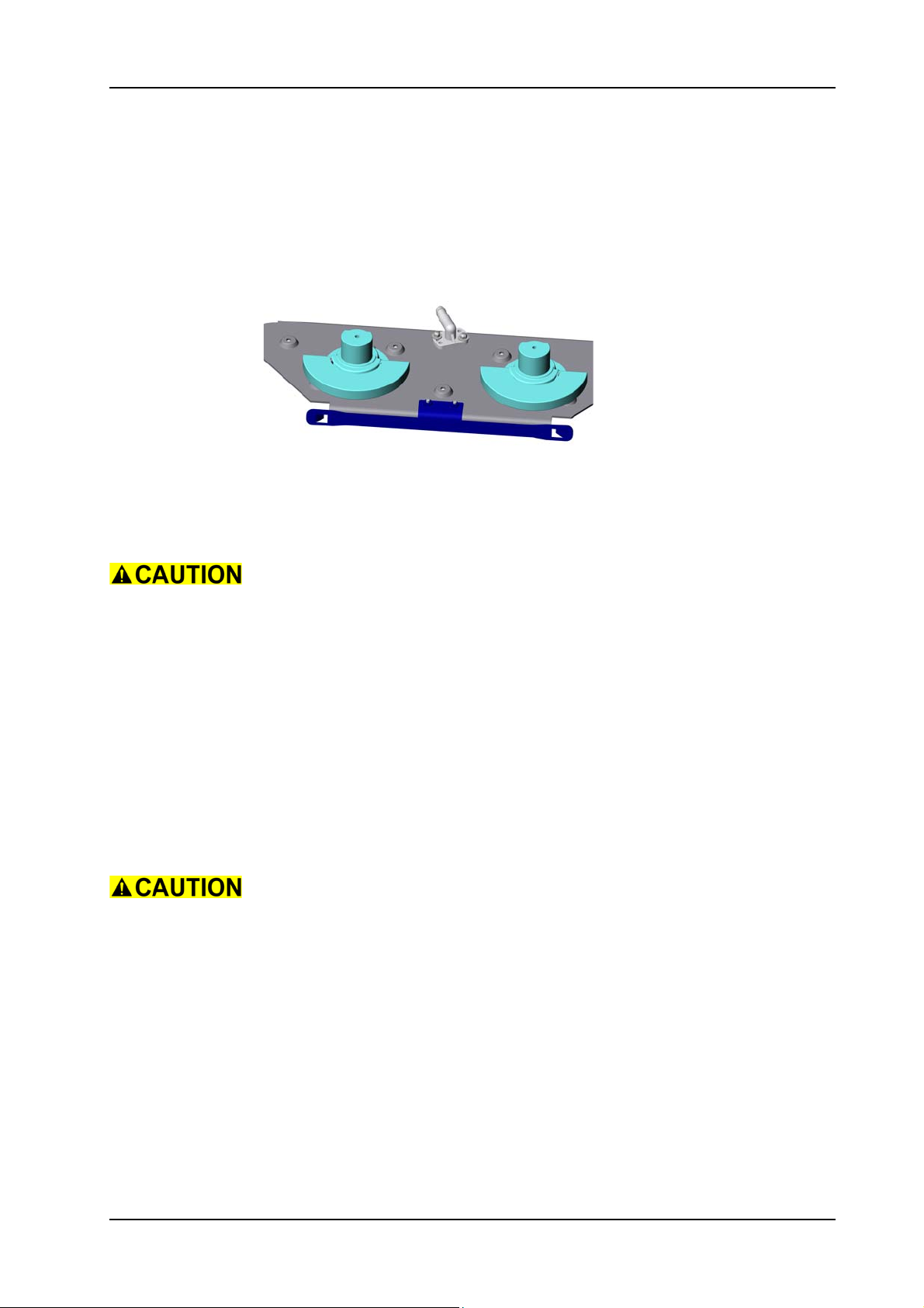
GTS Technical Manual
5.9 Brush drive
5.9.10 Mounting of eccentric shaft XP-M
Picture 91: Eccentric shaft
• Position the eccentric shaft.
• Mount the three self-locking nuts M6.
• Carefully mount brush console.
Take care when positioning the brush console that it does not tilt.
• Turn the brush unit up side down.
• Mount the bevel gears and the screws.
Service
Fix the screws (09/104) of the bevel gears with adhesive locking (09/
160).
Lubricate brush console bearings (09/134) and eccentric shaft (09/
05.68.85 brush drive - eccentric shaft - XP_M_V1.00.fm
124) with ball bearing grease (04/164) as a water-repellent.
•Mount the hoses.
Take care that you assemble the longer hose (05/121) on the RH of
the brush unit.
•Mount the hose clamps.
• Complete assembling the brush belt according to the chapter
MOUNTING OF BRUSH BELT & BRUSH MOTOR XP-M.
• Complete assembling the synchronisation according to the
chapter MOUNTING OF SUPPORT WITH BEARING
(SYNCHRONISATION) XP-M.
• Complete assembling the brush unit according to the chapter
MOUNTING OF COMPLETE BRUSH UNIT XP-M.
28. November 2014 Edition: V1.00/2014 5-63
Copyright © 2014, Diversey Care
Page 87
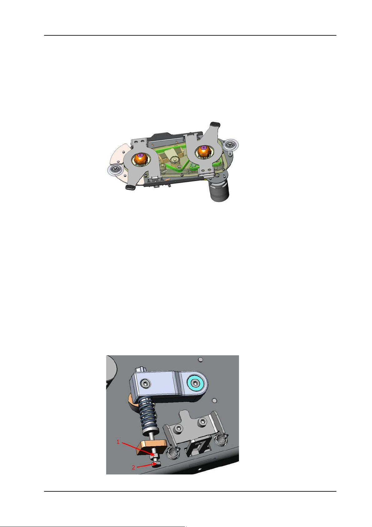
GTS Technical Manual
5.9 Brush drive
5.9.11 Removing of brush belt XP-R
Picture 92: Brush belt
05.68.21 brush drive - brush belt - XP_R_V1.00.fm
• Remove brush drive according to chapter REMOVING OF
COMPLETE BRUSH UNIT XP-R.
• Remove the motor gasket (10/104).
• Remove the 10 screws (10/102) for the two brush covers (10/
101 and 103).
• Remove the brush covers.
Remarks
Further numbering refers to picture: Clamping piece.
1 Loosen fixation nut (10/141) of the tension screw (10/118).
2 Loosen the tension screw to turn the tension lever (10/108).
• Turn the center screw completely out to release the tension of
the brush belt.
• Remove the pressure spring (10/116) and the flange bolt (10/
117) to move the tension lever to the end stop.
Picture 93: Tension lever
28. November 2014 Edition: V1.00/2014 5-64
Copyright © 2014, Diversey Care
Page 88
GTS Technical Manual
• Remove the 4 tension springs (10/140) of the decoupling bows
(11/143).
• Remove one circlip (11/145) from the bolt (11/146).
• Pull out the bolt and remove the decoupling bow.
Picture 94: Decoupling bow
Remarks
You need to remove the LH and RH side decoupling bow.
05.68.21 brush drive - brush belt - XP_R_V1.00.fm
• Remove the 8 screws (10/102) of the protective cover (10/145).
• Remove the protective cover.
• Remove the brush belt (11/125).
28. November 2014 Edition: V1.00/2014 5-65
Copyright © 2014, Diversey Care
Page 89
GTS Technical Manual
5.9 Brush drive
5.9.12 Mounting of brush belt XP-R
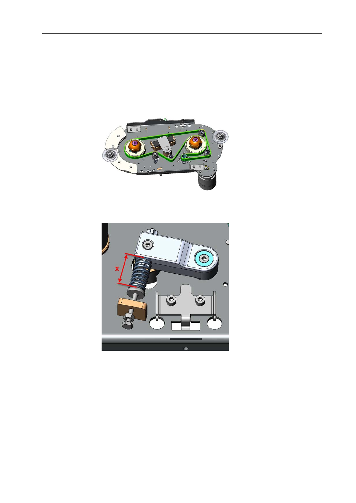
Picture 95: Brush belt mounting
05.68.21 brush drive - brush belt - XP_R_V1.00.fm
• Position the brush belt carefully.
• Position the pressure spring and bolt onto the tension lever.
1
Picture 96: Tension lever adjustment
• Turn the center screw to tension the brush belt.
Adjustment
Tension the clamping lever until the distance of the spring has the
value x=50mm according to the picture.
• Position and tighten the fixation nut of tension screw from the
tension lever.
28. November 2014 Edition: V1.00/2014 5-66
Copyright © 2014, Diversey Care
Page 90

GTS Technical Manual
Adjustment
Turn the coupling hubs (11/128) by hand in opposite direction to
ensure that the belt is correctly mounted and stays in the middle of
the pulley.
• Position the protective cover onto the brush unit.
• Position and tighten the 8 screws of the protective cover.
Ensure that the brush belt does not touch the cover.
• Position the decoupling bow.
• Mount the axles and position the circlips.
• Mount the tension springs of the decoupling bows.
• Position the two brush covers onto the brush unit.
• Position and tighten the 10 screws for the two covers.
• Complete assembling according to chapter MOUNTING OF
COMPLETE BRUSH UNIT XP-R.
05.68.21 brush drive - brush belt - XP_R_V1.00.fm
28. November 2014 Edition: V1.00/2014 5-67
Copyright © 2014, Diversey Care
Page 91
GTS Technical Manual
5.9 Brush drive
5.9.13 Removing of brush pulley XP-R
05.68.41 brush drive - pulley - XP_R_V1.00.fm
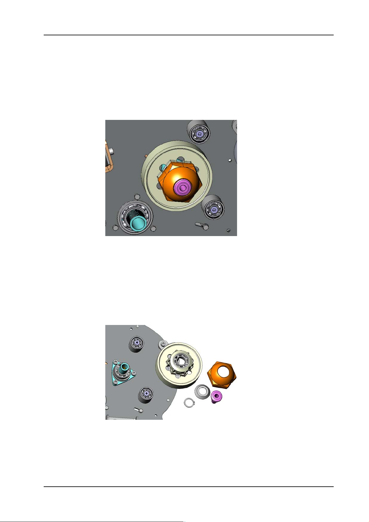
Picture 97: Brush pulley
• Remove the brush drive according to chapter REMOVING OF
BRUSH DRIVE UNIT XP-R.
• Remove brush belt according to chapter REMOVING OF BRUSH
BELT XP-R.
• Remove the coupling hub (11/128) carefully with a screw driver.
• Remove the centre plug (11/129) and the sealing ring (11/127).
• Remove the retaining ring (11/126).
• Pull off the pulley (11/124 and/or 11/130) from the bracket
(111/121).
Picture 98: Brush pulley mounting
Remarks
If you have to remove the complete pulley and axle together then you
can remove the three screws (11/122) with an A lle n ke y by pos iti oni ng
the slot of the pulley (11/124 and/or 11/130) right over the screws.
28. November 2014 Edition: V1.00/2014 5-68
Copyright © 2014, Diversey Care
Page 92
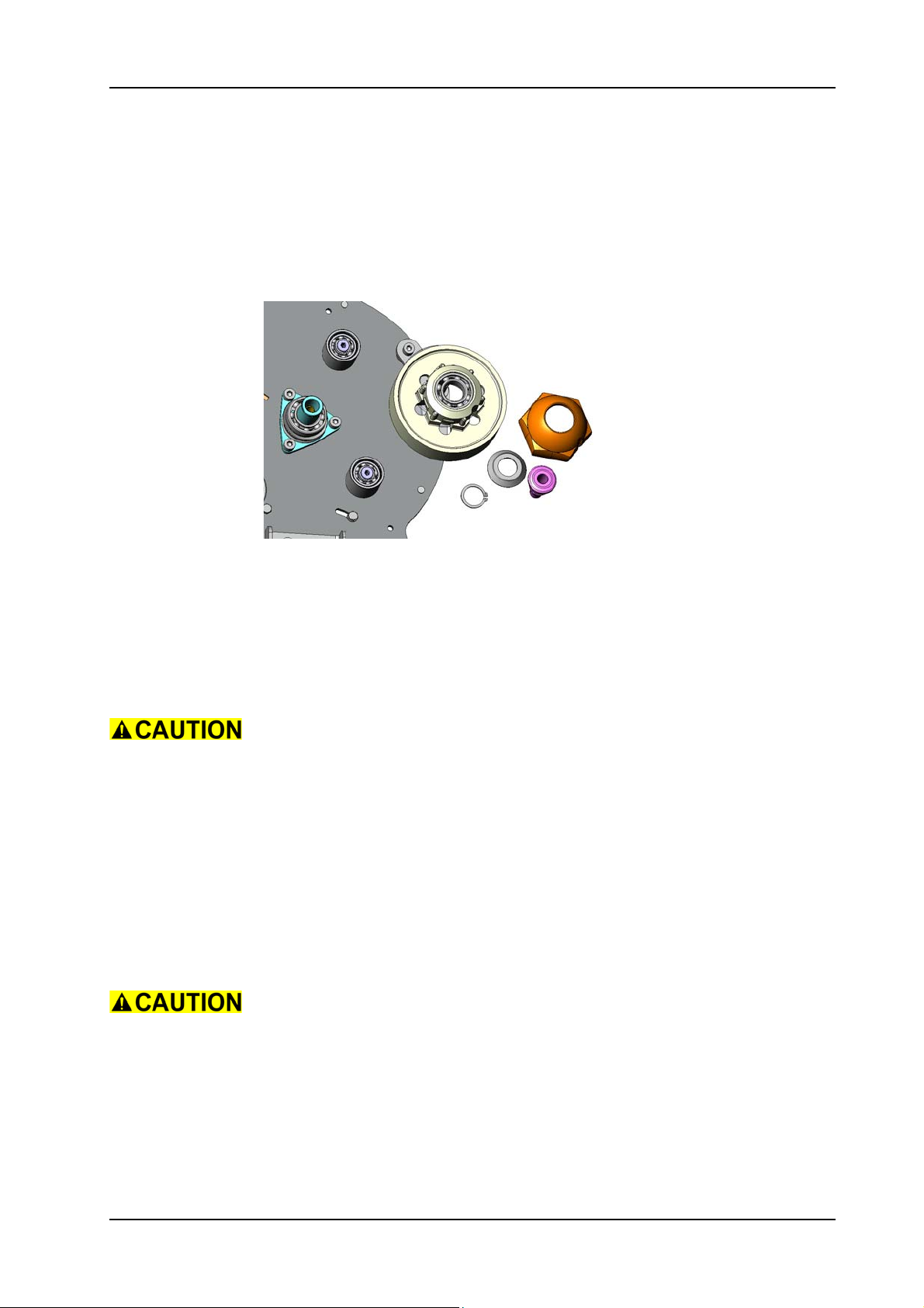
GTS Technical Manual
5.9 Brush drive
5.9.14 Mounting of brush pulley XP-R
05.68.41 brush drive - pulley - XP_R_V1.00.fm
Picture 99: Brush pulley mounting
• Mount the pulley onto the axle.
Service
Apply gear/bearing lubricant (11/160) on the pulley (11/124 and/or
11/130), the bracket (11/121) and sealing ring (11/123).
The brush pulley with the position number (11/124) got grooves on
it. Please ensure that it is mounted onto the correct support, refer to
e-spares.
• Position the retaining ring.
• Mount the center plug and the sealing ring.
Service
Apply lubricant onto the sealing ring (11/127).
• Mount the coupling hub.
The coupling hub is coded and has to match to the pulley. Use a
wooden piece and a hammer to mount the coupling hub onto the
pulley.
28. November 2014 Edition: V1.00/2014 5-69
Copyright © 2014, Diversey Care
Page 93
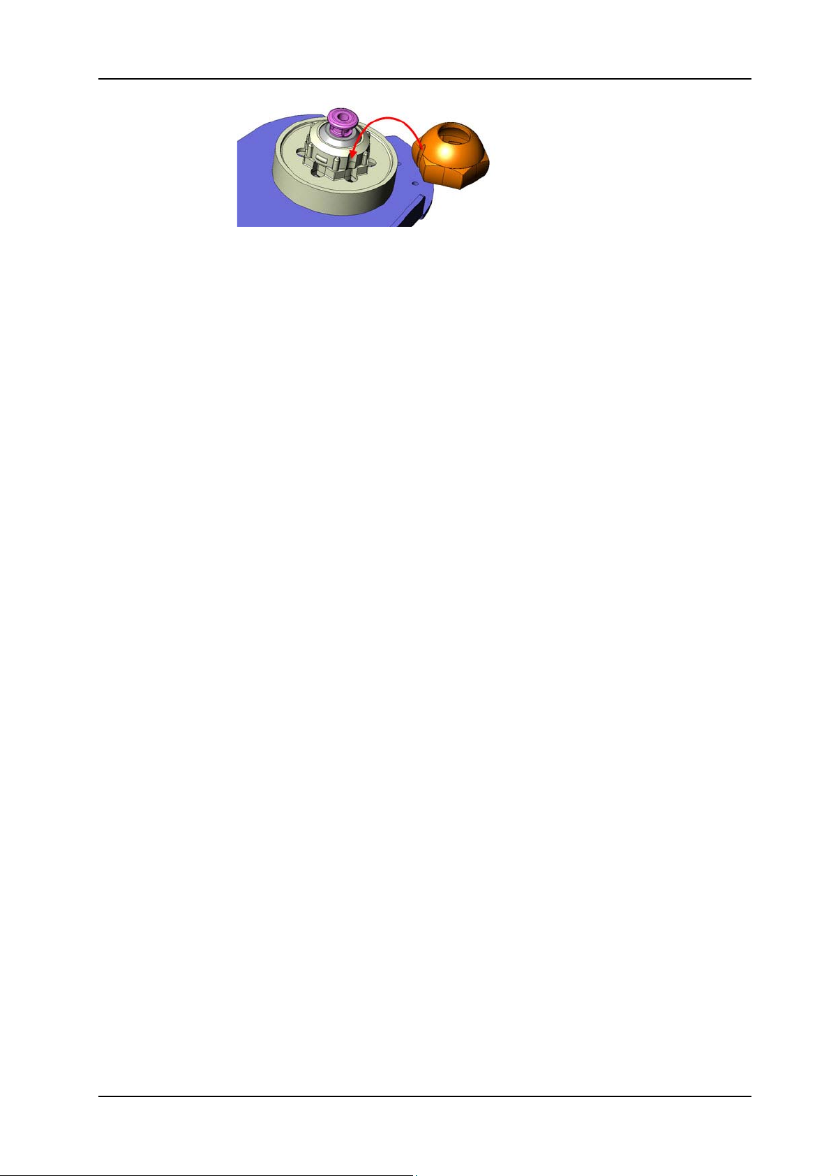
GTS Technical Manual
Picture 100: Brush pulley
• Complete assembling according to chapter MOUNTING OF
BRUSH BELT XP-R.
• Complete assembling according to chapter MOUNTING OF
COMPLETE BRUSH DRIVE UNIT XP-R.
05.68.41 brush drive - pulley - XP_R_V1.00.fm
28. November 2014 Edition: V1.00/2014 5-70
Copyright © 2014, Diversey Care
Page 94
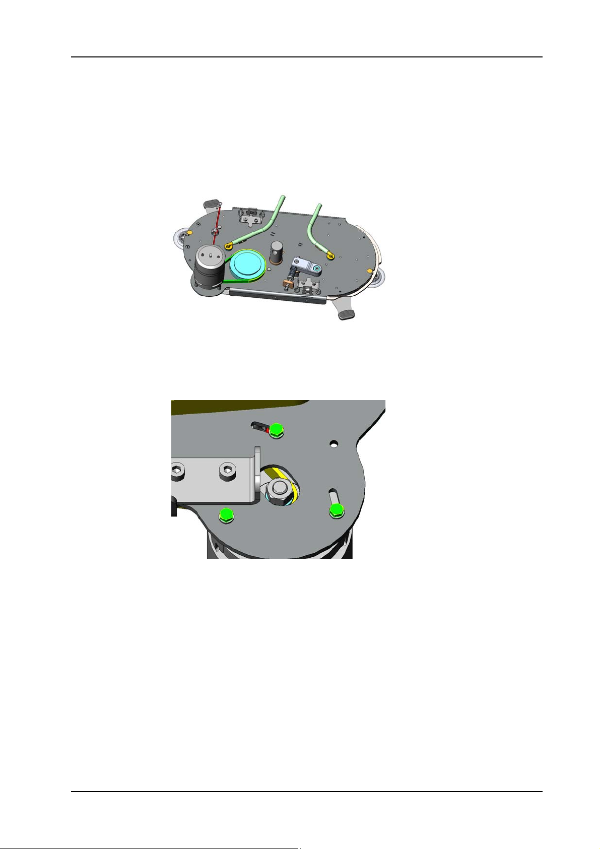
GTS Technical Manual
5.9 Brush drive
5.9.15 Removing of motor & motor belt XP-R
Picture 101: Brush motor belt
05.68.58 brush drive - motor & motor belt - XP_R_V1.00.fm
• Remove brush drive according to chapter REMOVING OF
COMPLETE BRUSH DRIVE UNIT XP-R.
• Remove the brush and belt covers according to chapter
REMOVING OF BRUSH BELT XP-R.
Picture 102: Brush motor mounting
• Remove the three screws (10/131) and washers (10/130) of the
brush base plate (10/115).
• Remove the brush motor (10/125) and/or the motor belt (10/
151).
28. November 2014 Edition: V1.00/2014 5-71
Copyright © 2014, Diversey Care
Page 95
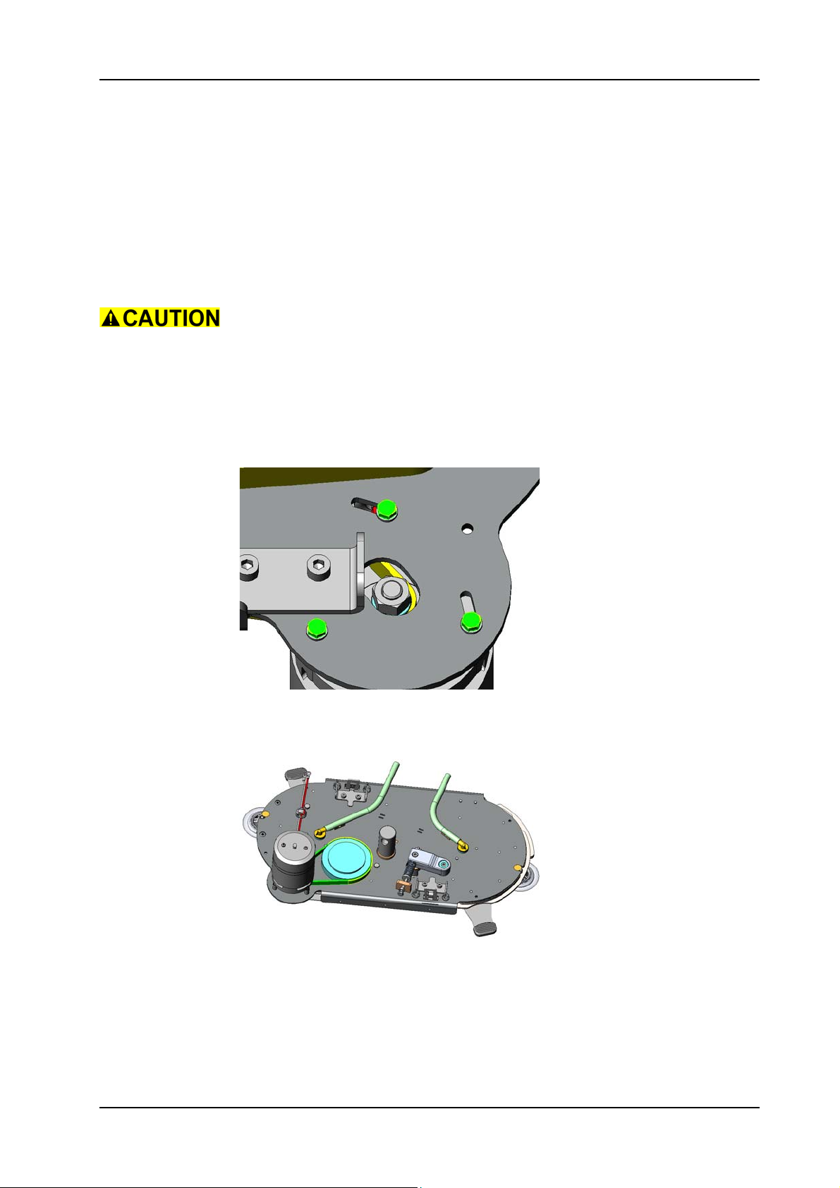
GTS Technical Manual
5.9 Brush drive
5.9.16 Mounting of motor & motor belt XP-R
• Position the new motor/new belt.
Take care that the belt is positioned correctly.
• Position the screws and washers.
Service
Apply adhesive locking (10/170) on the screws (10/131).
05.68.58 brush drive - motor & motor belt - XP_R_V1.00.fm
Picture 103: Brush motor mounting
• To tension the belt move the motor into position.
• Tighten all screws.
Picture 104: Brush motor belt
• Complete assembling according to the chapter MOUNTING OF
BRUSH BELT XP-R.
• Complete assembling according to the chapter MOUNTING OF
COMPLETE BRUSH UNIT XP-R.
28. November 2014 Edition: V1.00/2014 5-72
Copyright © 2014, Diversey Care
Page 96
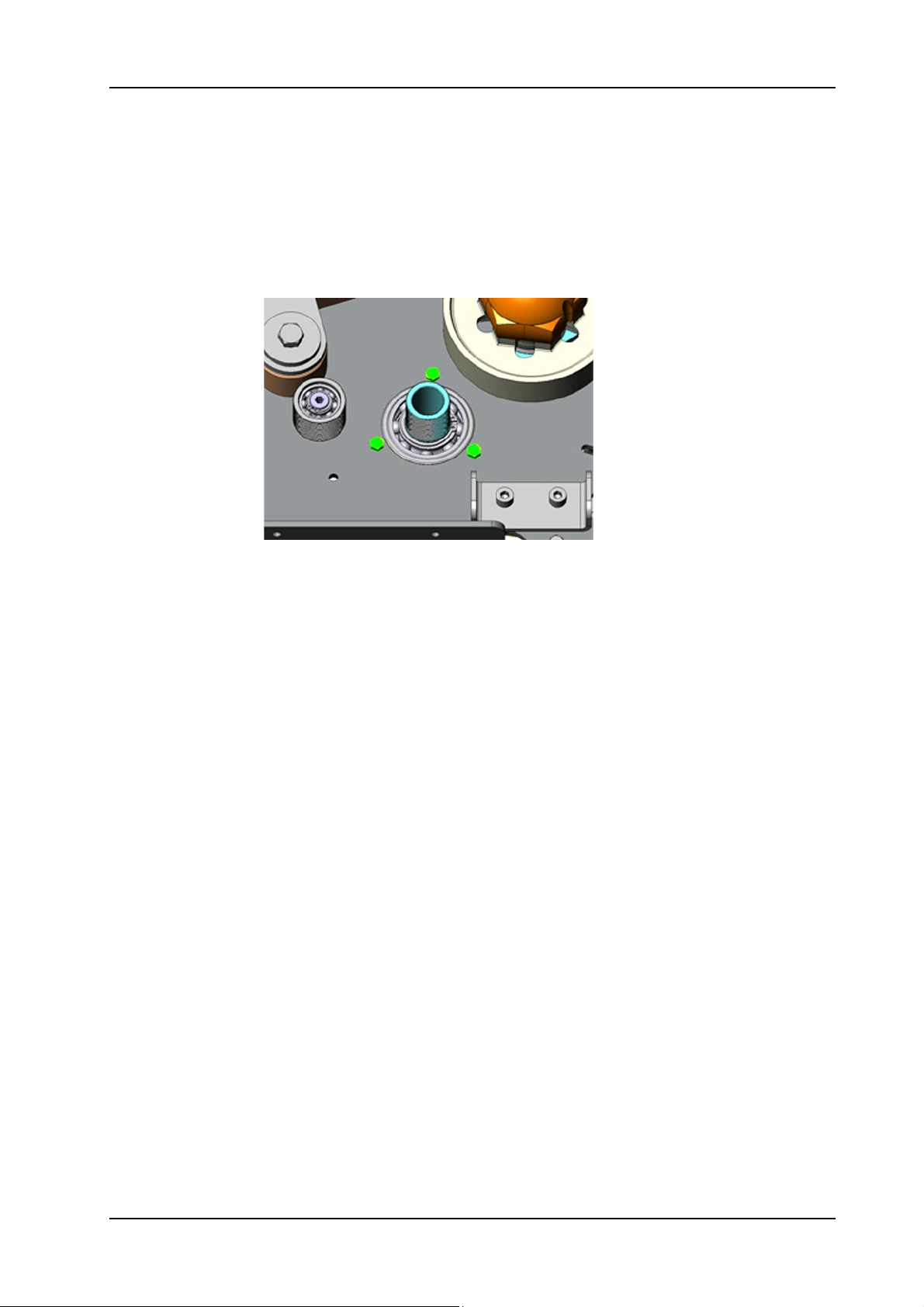
GTS Technical Manual
5.9 Brush drive
5.9.17 Removing of intermediate pulley XP-R
05.68.76 brush drive - intermediate pulley - XP_R_V1.00.fm
Picture 105: Intermediate pulley
• Remove brush drive according to chapter REMOVING OF
COMPLETE BRUSH UNIT XP-R.
• Remove brush belt according to chapter REMOVING OF BRUSH
BELT XP-R.
• Remove motor belt according to chapter REMOVING OF MOTOR
& MOTOR BELT XP-R.
• Remove the three screws (10/132) for the intermediate pulley
(10/110).
• Remove the complete intermediate pulley.
28. November 2014 Edition: V1.00/2014 5-73
Copyright © 2014, Diversey Care
Page 97
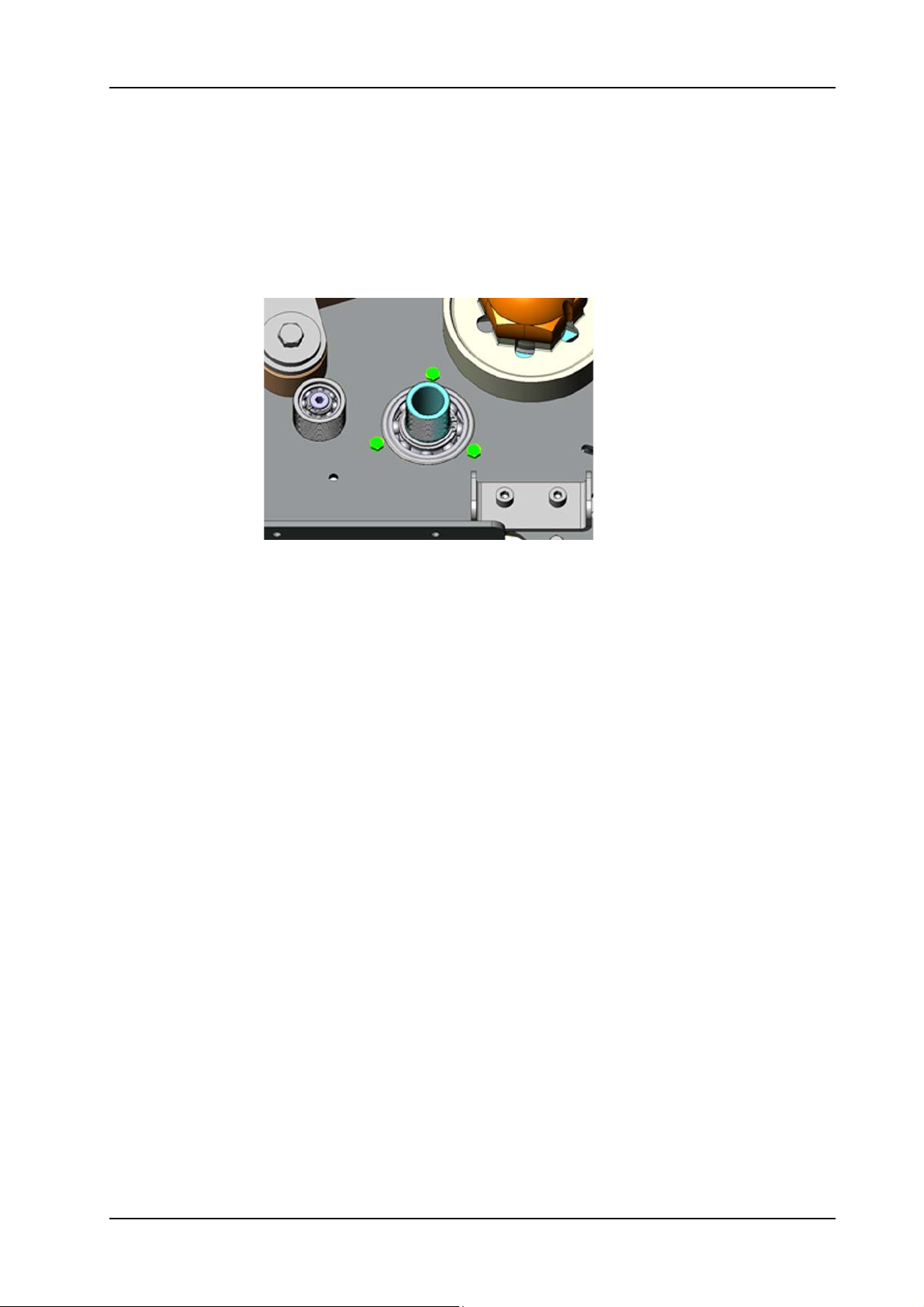
GTS Technical Manual
5.9 Brush drive
5.9.18 Mounting of intermediate pulley XP-R
05.68.76 brush drive - intermediate pulley - XP_R_V1.00.fm
Picture 106: Intermediate pulley
• Mount the new intermediate pulley.
• Position and tighten the three screws.
• Complete assembling according to the chapter MOUNTING OF
MOTOR & MOTOR BELT XP-R.
• Complete assembling according to the chapter MOUNTING OF
BRUSH BELT XP-R.
• Complete assembling according to the chapter MOUNTING OF
COMPLETE BRUSH UNIT XP-R.
Remarks
The intermediate pulley is seperate and as set available. Refer to espares.
28. November 2014 Edition: V1.00/2014 5-74
Copyright © 2014, Diversey Care
Page 98

Technical Manual
6 Electrical
28. November 2014 Edition: V1.00/2014
Copyright © 2014, Diversey Care
Page 99
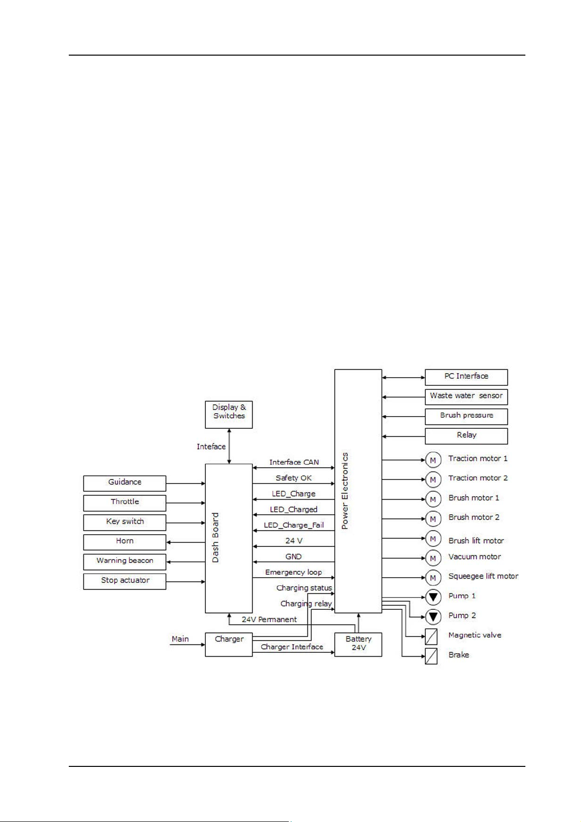
GTS Technical Manual
6.1 System architecture
6.1.1 General
• The firmware is memorised only on the power electronics.
• The dashboard visualises the states of the machine. It also
functions as a connection between the power electronics and the
devices (e.g. hall sensor, key switch and foil keyboard).
• Applying the correct torque where required is essential for a safe
operation of the machine.
• ESD can harm the electronic boards and therefore reduce the life
time of the machine. Use always an ESD bag to protect them.
06.10.18 system architecture - XP_M_R_V1.00.fm
Picture 1: System architecture
28. November 2014 Edition: V1.00/2014 6-1
Copyright © 2014, Diversey Care
Page 100
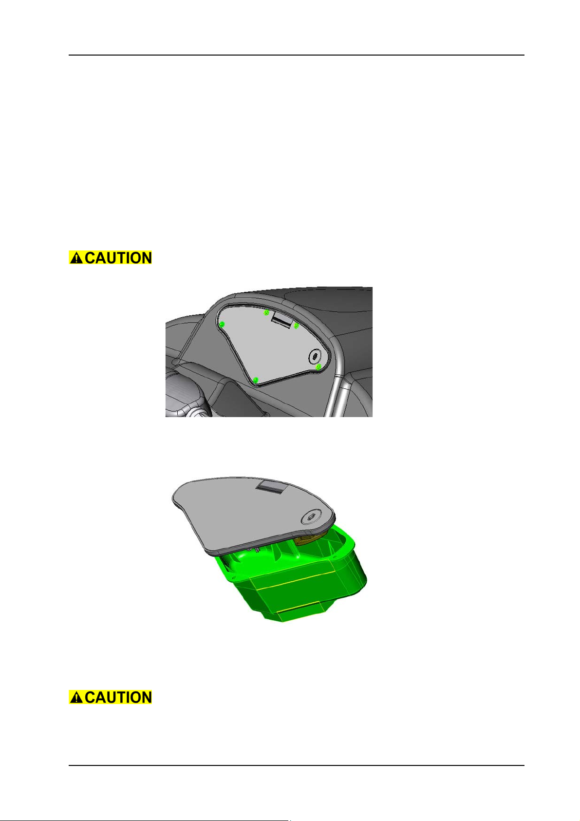
GTS Technical Manual
6.2 Dashboard
6.2.1 Removing of dashboard
Remarks
For the correct connection of the aggregates and wires please refer to
the chapter: DASHBOARD CONNECTIONS.
Do not damage the dashboard by improper placement of screws.
06.14.21 dashboard - XP_M_R_V1.00.fm
Picture 2: Dashboard position of screws
• Remove the 5 screws (02/120) for the dashboard (02/125).
• Slowly pull out the dashboard from the tank cover (02/102).
Picture 3: Dashboard cover
• Remove the dashboard from the cover (02/119).
• Disconnect all electrical connections to the dashboard.
Be cautious when removing the dashboard as you can damage the
wires or the ribbon cables of the dashboard. Disconnect all electrical
connections to dashboard.
28. November 2014 Edition: V1.00/2014 6-2
Copyright © 2014, Diversey Care
 Loading...