

SeaLand Dometic VacuFlush Series Installer's Manual
VacuFlush
®
Installer’s Guide
This book belongs to ________________
0
VacuFlush
SeaLand recommends that the
OEM label key sanitation system
components: such as vacuum
generators, wye valves and
directions, seacocks, etc.
®
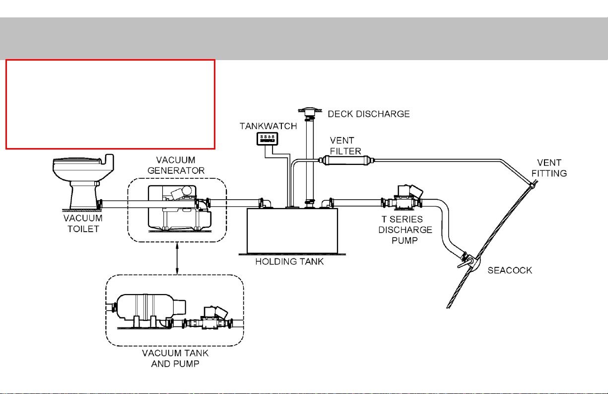
System Components
VacuFlush® toilet systems are not difficult to
install BUT certain steps are CRITICAL and
must be followed as described. These areas
are highlighted throughout this guide in RED.
1
VacuFlush
®
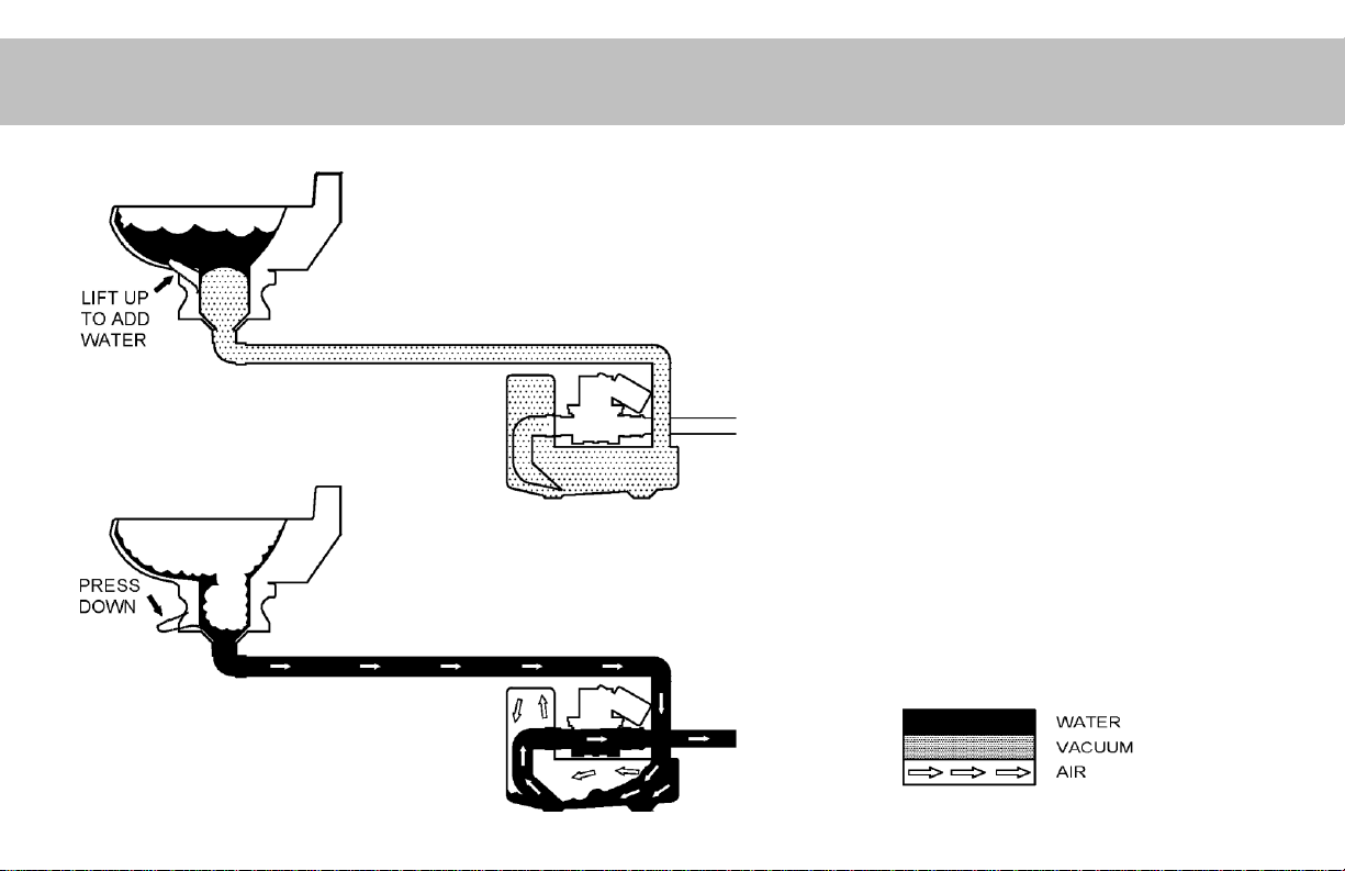
Principles of Operation
• Uses pressure difference between
atmosphere and vacuum in the tank.
• The vacuum pump is activated by the
loss of vacuum in the vacuum tank.
• Vacuum is maintained at all times.
The “leak-down” time period should be
approximately three hours. (The
pump should not come on within a
three hour window of non-use.)
• Recharging vacuum takes less than a
minute.
2
Note: Magnum Opus and VHT Installations are shown in other Installation Guides
VacuFlush® System Components
VacuFlush® Principles of Operation
Table of Contents ………………….
Section I: Toilet Installation …….
• Critical Mounting Clearances ………..
• Standard Discharge Configurations ...
• Toilet Base & Through-floor Funnel
Installation Guidelines ………………
• Solvent Bonding ……………………….
• Incoming Water Supply ………………
• Keep Debris Out of the Toilet ………..
• CRITICAL GUIDELINES …………….
Section II: Vacuum Sources …….
• Vacuum Pump Locations …………….
• Supporting the Vacuum Hose ……….
• S-Series Pump ………………………..
• Sailboat Pump Mounting ……………..
• Vacuum Tank Do’s and Don’ts ………
• Accessibility ……………………………
• CRITICAL GUIDELINES ……………..
Arrow indicates
extremely
critical items
Table of Contents
Section III:
1
Hose and Piping Layout ………….
2
• Piping Runs to the Vacuum Source ….
3
• Bend Limits …………………………….
4
• Hose Run Simplification ……………….
5
• Avoiding Heat Sources ………………..
6
• Routing Hose and Piping ……………..
• Making Hose Connections …………….
9
11
12
13
14
15
16
17
18
19
20
21
25
–Hose Heaters & Assembly …………………
–Lubrication …………………………………..
–Assembly Tips ………………………………
• Avoiding Malodors ……………………..
• SeaLand Fitting Information …………..
• CRITICAL GUIDELINES ……………..
Section IV: Holding Tanks ……….
• Simplified layout ……………………….
• Holding Tank Locations ……………….
• Diptubes ………………………………..
• Vent Filters ……………………………..
• Discharge Pump ……………………….
• Level Indicators ………………………..
• CRITICAL GUIDELINES ……………..
Section V: Electrical Guidelines …
• CRITICAL GUIDELINES ……………..
26
27
29
30
31
32
34
34
35
36
37
39
42
43
44
46
48
49
50
51
52
53
53
Section VI: System Checkout .
• Power On Check ………………….
• Winterizing the System …………..
• System Leak Rates ……………….
Section VII:
System Troubleshooting ……
1. Water will not stay in the bowl ………
2. Plastic flush ball will not close ………
3. Plastic flush ball will not open ………
4. Water doesn’t shut off in toilet ……..
5. Water does not enter toilet properly .
6. Cannot lift flush lever to add water
to the bowl …………………………….
7. Water is leaking from the water
valve assembly ……………………….
8. Water is leaking from the rear of
toilet……………………………………
9. Water is leaking from the base/bowl
Connection ……………………………
10. Pump is running too often ………….
11. Pump runs continuously …………….
12. Pump will not run …………………….
13. Vacuum pump runs too slowly, very
hot, or blows fuses frequently ……..
14. Toilet will not flush …………………...
15. Pump leaks water ……………………
54
55
56
57
58
58
59
59
60
61
62
62
63
63
64
65
66
67
68
69
3
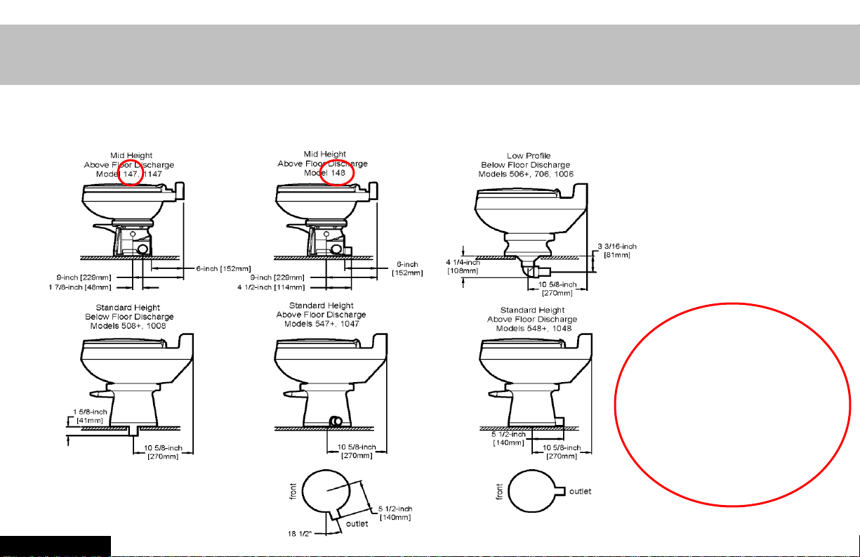
Section I: Toilet Installations
SeaLand toilets are available in many different outlet configurations.
Please review a SeaLand brochure for current model information.
HINT: If the Model
Number has a zero in
the middle, the toilet
discharges through the
floor.
For models
with 147 or 148
the connection
must be a hose
connection, not
a glued joint.
Section I
4
REAR
SIDE
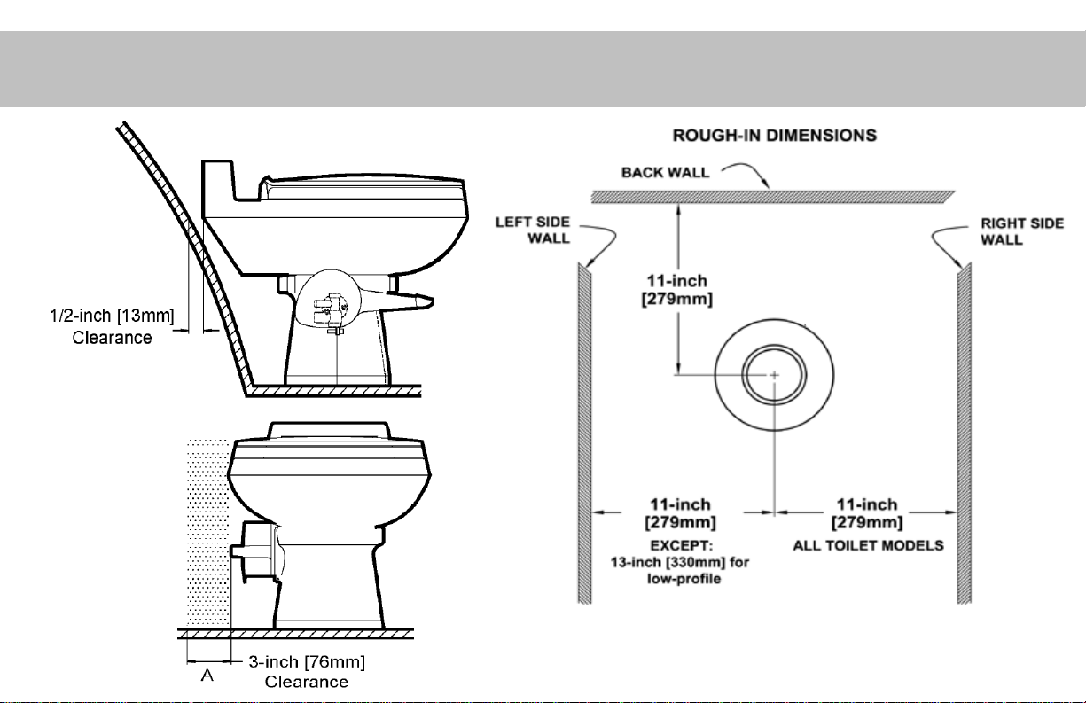
Critical Toilet Mounting Clearances
Location of the floor hole
for the toilet discharge
5

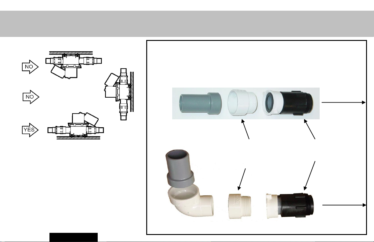
Above the Floor Discharge - Side and Rear
These joints require
SOLVENT BONDING per
procedure on page 11!
Cannot be used with models
90 Elbow Detail
ending in 147 or 148.
Section I
6
Through Floor Funnel Comparison
Standard through the floor funnel
Quick turn funnel
2 3/4” (70mm)
4” (102mm)
8 1/2” (216mm)
minimum bend
radius
Standard below the floor discharge with hose
7
Below the Floor Discharge
This joint requires
SOLVENT BONDING per
procedure on page 11!
-08 Model Detail
Section I
8
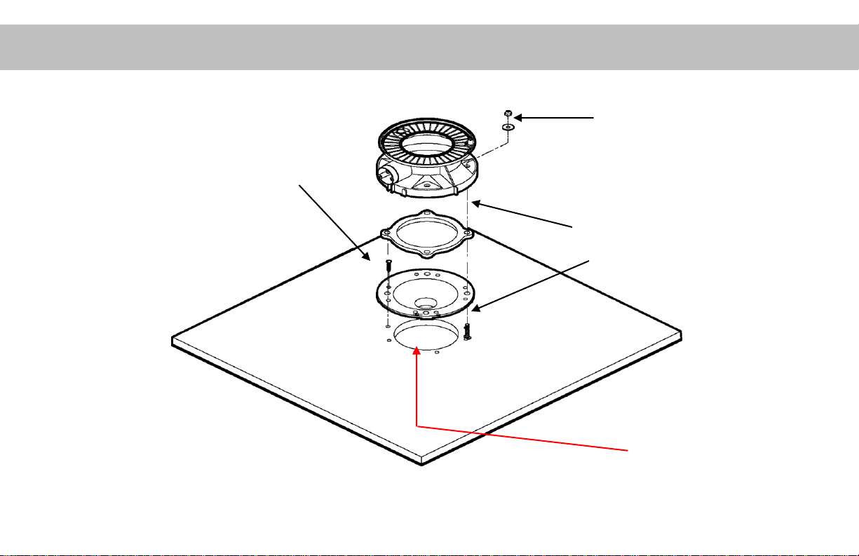
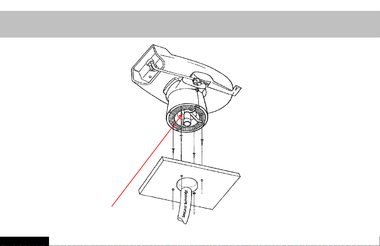
Toilet Base & Through-floor Funnel Installation Guidelines
Through-floor funnels must…
• be mounted securely with 8
screws (not provided).
• Mounted flush with floor
• Screw heads must be flush or
lower than the top of the floor
flange funnel.
Through-floor funnels
are pre-assembled
and can be positioned
at 90 points from front
of toilet.
Use FULL scale template for cutting holes
(available in the SuperTech Manual).
Toilet base must be
securely fastened with 4
fasteners (provided).
Bottom of the toilet base and
the bottom of the through-
floor funnel must be
mounted on the same
surface.
No gaps allowed
between funnel and
floor.
Follow SOLVENT
BONDING per procedure
per page 11 for
connecting fitting to
bottom of the funnel!
9
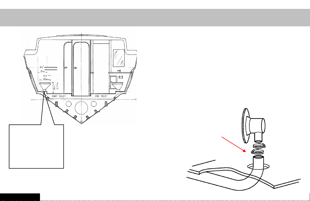
When there is NO room…. Use this Quick Turn Funnel
Special Quick Turn Funnel - must be
special ordered - P/N 385310550
(Can only be installed with models that
use a separate floor flange funnel, like
the models ending in -06.)
This joint requires PROPER
HOSE CONNECTION per
Limited space
under the
deck, despite
the size of the
boat.
procedure on pages 34-36!
Section I
10
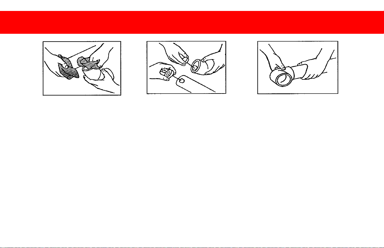
Solvent Bonding For Rigid Pipe & Fittings
1 2 3
Cleaner
Cement Twist
The most important steps:
1. Use a PVC cleaner on both bonding surfaces.
2. Use a PVC cement (must contain
Tetraheyrofuran) on both bonding surfaces.
3. Connect parts using a twist and hold motion until
the glue is set.
4. Let joint cure for at least four hours or per
instructions on the container. (Cold temperatures
require longer cure times.)
11
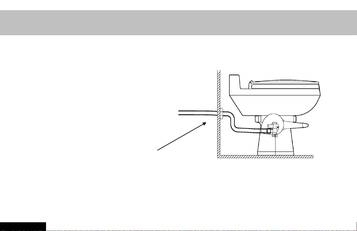
Incoming Water Supply
The incoming water line MUST…
• Be cold water ONLY
• Be ½” (13mm) MINIMUM ID
• Provide a MINIMUM flow of 2
gallons/min (7.6 liters/min) at the
toilet. This requires a 2.8 GPM
(10.6 l/m) demand pump, or
greater depending on line
restrictions.
• Include a SHUT-OFF valve for
maintenance purposes
Fresh water is highly recommended. If the choice is made to use salt or
brackish flush water, SeaLand requires the use of a primary and secondary
filter. The secondary filter must be 100 mesh or less.
Section I
12
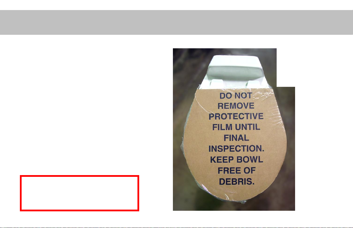
Keep Debris Out of the Toilet
• To prevent leaks, THE BALL
SEAL MUST BE PROTECTED
FROM DEBRIS. Keep the toilet
bowl covered.
• Lag bolts and/or T-bolts MUST
be securely fastened in FOUR
locations, or toilet wobble will
result.
• Should debris collect under the
ball seal, use the brush and
cleaner samples to remove
(provided with toilet).
Ball seal debris is THE MOST
COMMON installation
problem!!
Leave this
protective cover
in place until
final delivery.
13

Critical Guidelines – Toilet Installations
1. Allow proper clearances from rear and side objects (bulkheads,
partitions, etc).
2. When installing a funnel, secure the funnel flat against the floor
using 8 fasteners.
3. Fasten toilet securely to floor using 4 fasteners.
4. When installing a funnel, the bottom of the toilet base and the
bottom of the funnel flange must be mounted on the same surface.
5. Follow proper solvent bonding procedure for rigid PVC on page 11
when required.
6. Assure minimum incoming water supply of 2 gallons per minute
(7.6 liters/min) at the toilet.
7. Keep debris out of the toilet bowl/funnel DURING INSTALLATION to
avoid vacuum or water leakage through the ball seal.
Section I
14
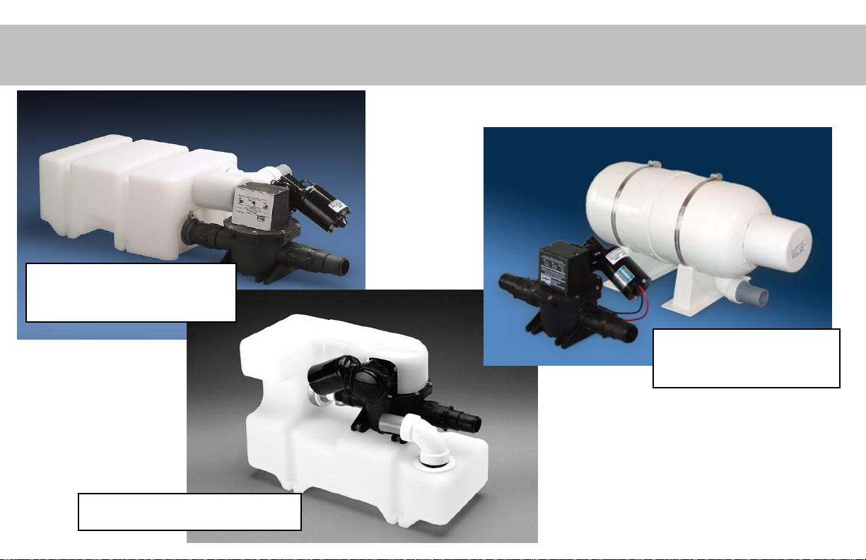
Section II: Vacuum Sources
Low-Profile Vacuum
Generator
Vacuum Tank and
Pump
Vacuum Generator
15
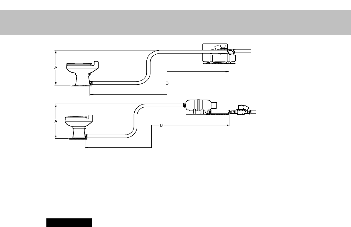
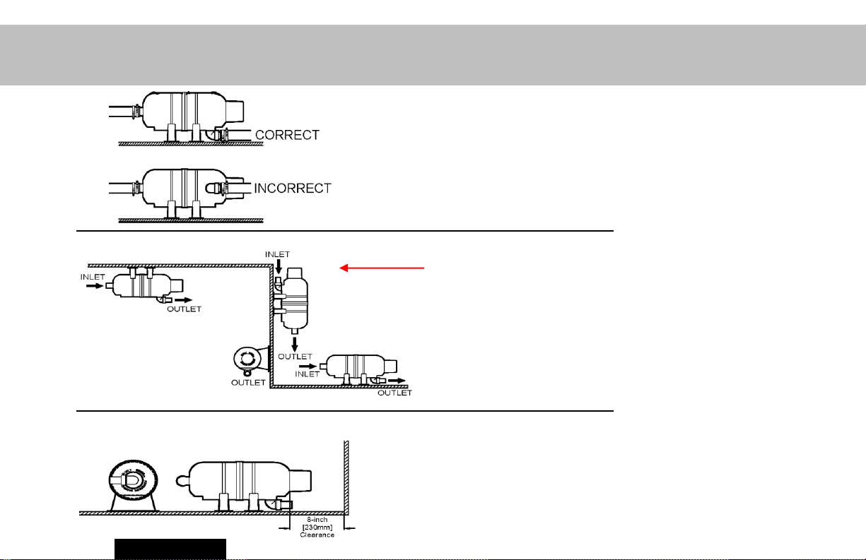
Locating the Vacuum Source
Each toilet must
have a separate
vacuum source
(vacuum
generator or
tank/pump).
A. Maximum height of vacuum piping from toilet outlet to vacuum source inlet is
6 feet (1.8 meters).
B. Maximum length of vacuum piping from toilet outlet to vacuum source inlet is
30 feet (9.1 meters).
Section II
16
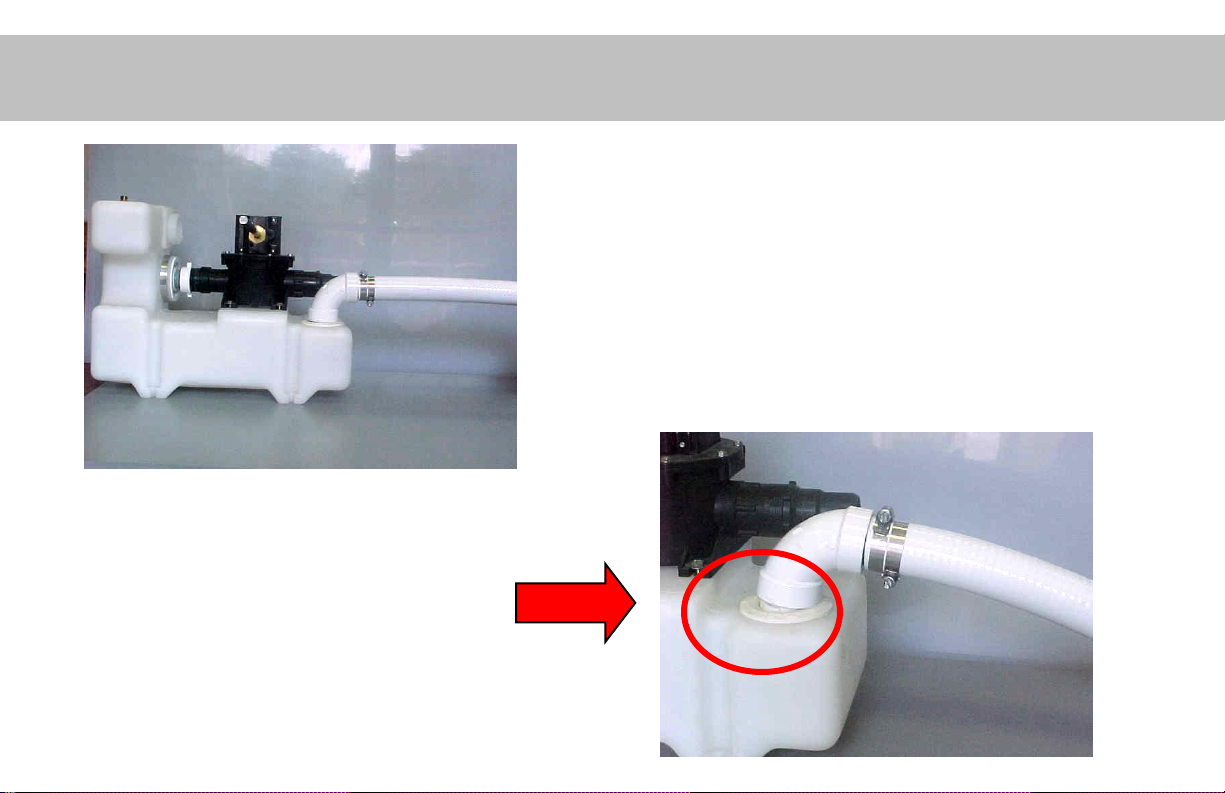
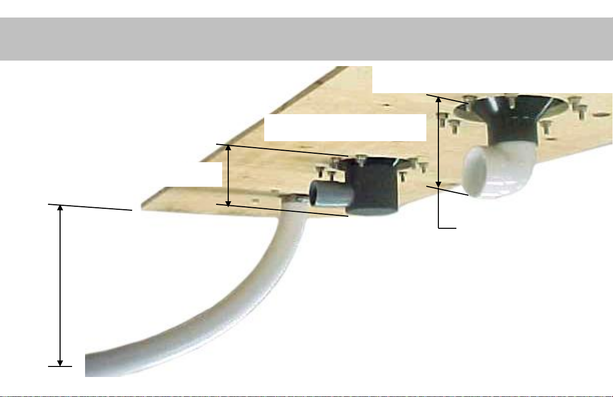
Supporting the Vacuum Hose
Do not let the hose go
unsupported (up or down). It
will pull the fitting out of the
seal, creating a leak.
The inlet hose of the vacuum
generator must not have a side
load (see picture below).
Support the hose, as necessary.
X
17
S-Series Vacuum Pump
• Mount pump horizontally
• Mount pump at same level or
lower than vacuum tank outlet.
Do not mount the pump higher
than the vacuum tank outlet.
Optional straight or 90º swivel quick-
disconnect fittings are available for suction &
discharge sides of vacuum pump.
307341513 –
hose connector
307341425 –
threaded fitting
To pump
385310728 –
swivel fitting
assembly
To pump
Section II
307341161 –
elbow
18

Sailboat Pump Mounting
Mounted athwartship (at
right angle to keel), need
15 incline to be
Mounted parallel
with keel, no incline
is needed.
acceptable.
When mounting S-Pump or Vacuum Generator athwartships (at right angle to keel) on
sailing vessels, compensate with a 15º incline on the discharge side.
19
Vacuum Tanks Do’s & Don’ts
• The outlet of the
vacuum tank must be
at the lowest level.
• The vacuum switch
must be on the top
when mounted
vertically.
• Proper clearance
must be allowed for
access to the
vacuum switch.
Never tamper
Vacuum levels
can ONLY be
adjusted at
with the
vacuum
switch!
factory!
Section II
20
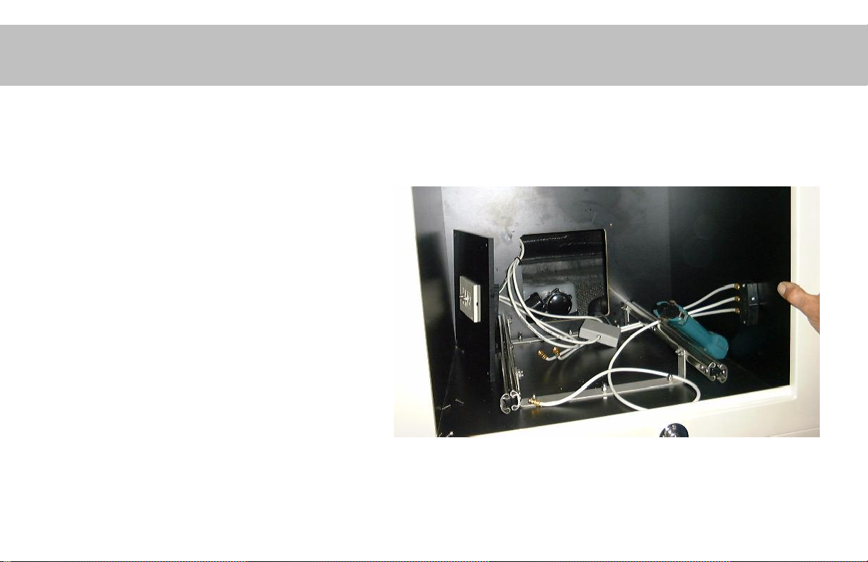
Accessibility is Critical!
• EASY access is needed to service
• Pumps
• Vacuum Switches
• Tank inlet and outlet fittings
• Vent Filters
• All pumps and tanks must have access to
replace if necessary.
Do NOT do this!! Insufficient
access.
X
Vacuum Generator is located behind an
appliance, difficult to access and entire unit can
not be replaced.
21
 Loading...