

SeaLand 3300 Series,3400 Series Owner's Manual
®
SeaLand
GRAVITY DISCHARGE TOILET
OWNER’S MANUAL
SeaLand® 3300, 3400 Series
All-Ceramic
Toilets
WARNING
!
This manual must be read and understood before installation, adjustment,
service, or maintenance is performed.
Modication of this product can
result in property damage.
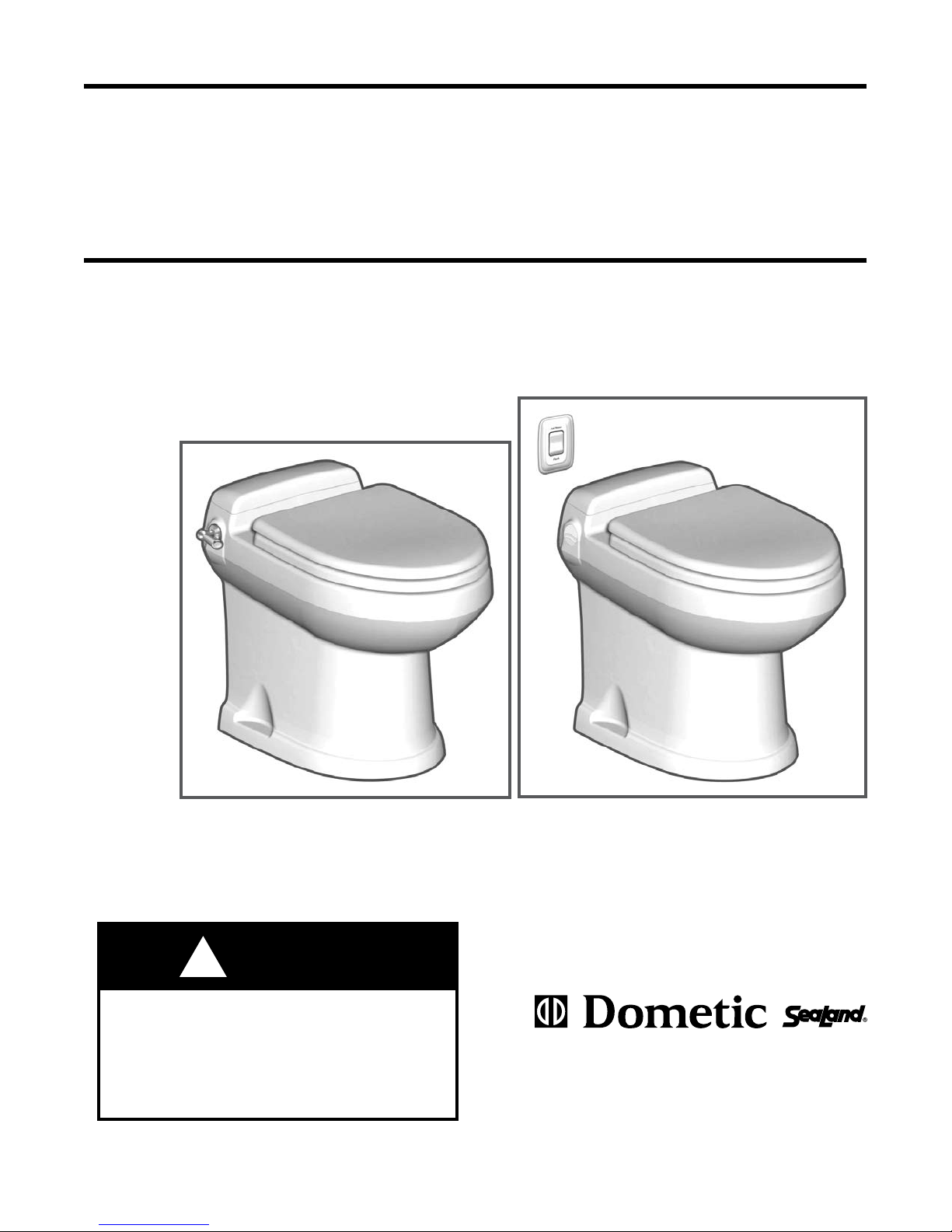
3300 Series
(with ush handle)
1
3400 Series
(with remote ush switch)
Dometic Sanitation Corporation
13128 State Rt 226, PO Box 38
Big Prairie, OH 44611
SeaLand Product Customer Service: 1-800-321-9886
www.DometicUSA.com
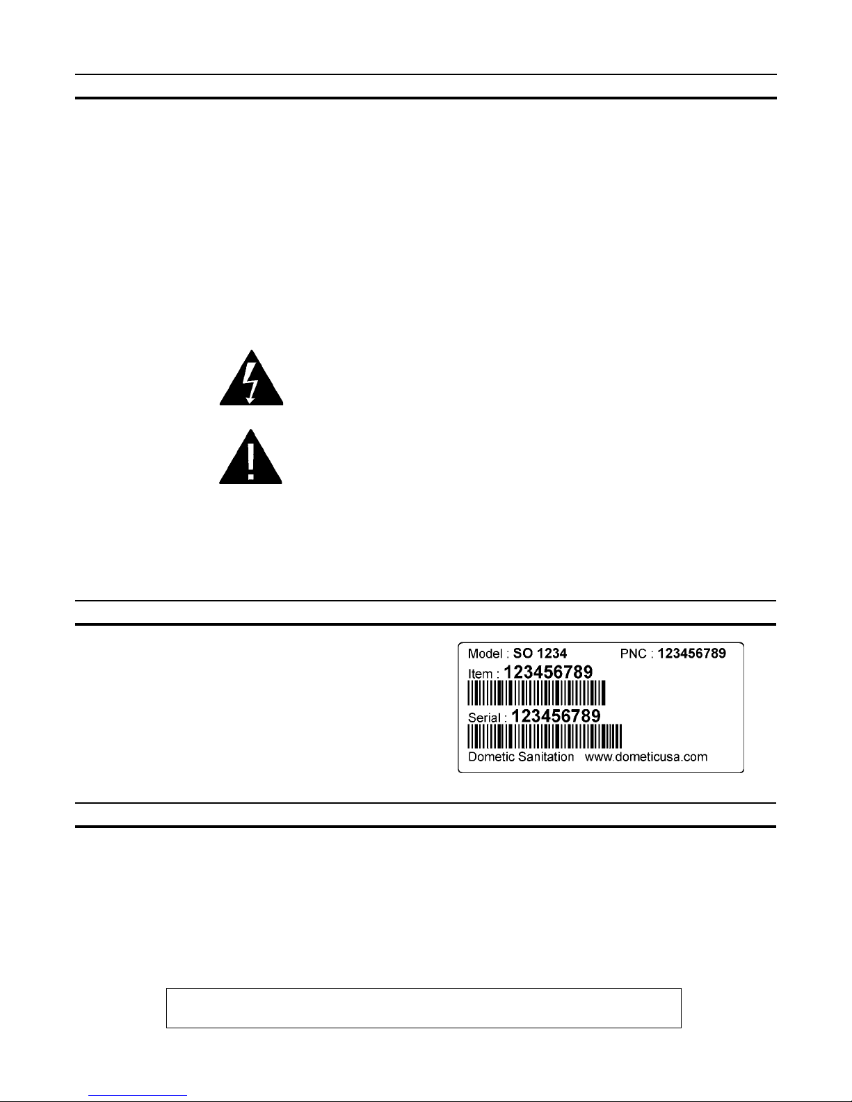
TABLE OF CONTENTS
Toilet Model Identication . . . . . . . . . . . . . . . . 2
Ordering Parts . . . . . . . . . . . . . . . . . . . . . . . . 2
Toilet Dimensions . . . . . . . . . . . . . . . . . . . . . . 3
Toilet Installation Instructions. . . . . . . . . . . 3 - 6
Remote Flush Switch Installation . . . . . . . . . . 7
Important Information Before Operation . . . . . 8
Electronic "Flush and Forget" Operation . . . . . 8
Toilet Controls . . . . . . . . . . . . . . . . . . . . . . . . . 8
Operating Instructions . . . . . . . . . . . . . . . . . . . 9
Automatic Flush Operation Timing Chart. . . . . 9
WARNING – ELECTRICAL SYSTEM.
Turn off electrical power before servicing.
WARNING – MOTOR STARTS AUTOMATICALLY.
Turn off electrical power before servicing.
Proper Cleaning and Maintenance . . . . . . . . 10
Manual Flush Operation . . . . . . . . . . . . . . . . 10
Winterizing . . . . . . . . . . . . . . . . . . . . . . . . . . 11
Spare Parts . . . . . . . . . . . . . . . . . . . . . . . . . . 11
Deodorants and Special Tissue . . . . . . . . . . 11
Flush Mechanism Components . . . . . . . . . . . 12
Electrical Specications . . . . . . . . . . . . . . . . . 13
Troubleshooting . . . . . . . . . . . . . . . . . . . 14 – 17
Wiring Diagrams . . . . . . . . . . . . . . . . . . . . . . 18
Customer Service . . . . . . . . . . . . . . . . . . . . . 19
Limited Warranty . . . . . . . . . . . . . . . . . . . . . 20
Read and understand the complete contents of this manual before operating or servicing the
toilet. Failure to follow these precautions may result in damage to the toilet.
TOILET MODEL IDENTIFICATION
The model identication label is located on the inside
wall of the toilet under the access cover. It will show the
model number and serial number.
ORDERING PARTS
Dometic is ready to assist you in the event service is required. Before calling, please have the following information
available. Your cooperation in having this information ready is appreciated and allows us to better meet your needs.
Please refer to the Parts Distributor list in the Customer Service section.
1. Toilet Model Number
2. Serial Number
3. Part Number, Description and Quantity (see Parts List)
SeaLand and Flush and Forget are registered trademarks of
Dometic Corporation.
2
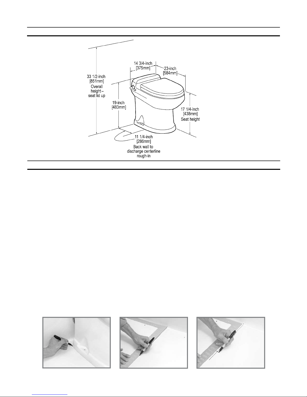
TOILET DIMENSIONS
TOILET INSTALLATION INSTRUCTIONS
System Requirements:
Dimensions may vary
±3/8-inch (13mm).
• 2 GPM (10.6 lpm) or larger water pump.
• 1/2-inch (12.7 mm) water line terminating in 1/2-inch MPT tting (to connect to toilet water supply hose).
• 4-bolt oor (closet) ange. SeaLand anges available include 3-inch spigot, socket, MPT, or 45-degree swivel
socket.
• 12 VDC through 7- or 8-amp fuse or circuit breaker. Use 14-gauge stranded copper wire.
IMPORTANT: If replacing an existing gravity-discharge toilet, make sure the center of the existing discharge
ange is at least 11-1/4 inches from the back wall, then proceed to Step 5 for proper positioning of water
line and electrical wiring.
STEP 1: Carefully unpack the toilet bowl, rear access lid and oor ange adapter. CAUTION: HANDLE THE VITREOUS CHINA TOILET AND ACCESS LID WITH CARE. SET THE LID IN AN AREA WHERE IT CANNOT BE
BROKEN. PLACE LID ON TOILET ONLY AFTER TOILET INSTALLATION IS COMPLETE.
STEP 2: Position the ceramic bowl in the space intended. Conrm that adequate clearance is available for using the
ush handle and opening the seat and lid.
STEP 3: Mark the oor at the rear corners of the toilet bowl (g. 1). Measure the distance between the two marks
and divide by 2 to nd the toilet centerline. Mark the oor at the rear wall for the centerline.
STEP 4: Place a carpenter’s square against the back wall, and draw a center line on the oor at least 14 inches
(356 mm) long (g. 2). Mark the centerline for the oor ange at 11-1/4 inches (286 mm) from the wall (g. 3).
Fig. 1
Fig. 2
3
Fig. 3
STEP 5a: For through-the-oor water line and electrical
wires, mark another centerline 6 inches (152 mm) from
the back wall (g. 4).
Fig. 4
Below-Floor Installation
STEP 5b: For through-the-wall water line and electrical
wires, mark a centerline 8 inches (203 mm) up from the
oor centerline (g. 5).
Fig. 5
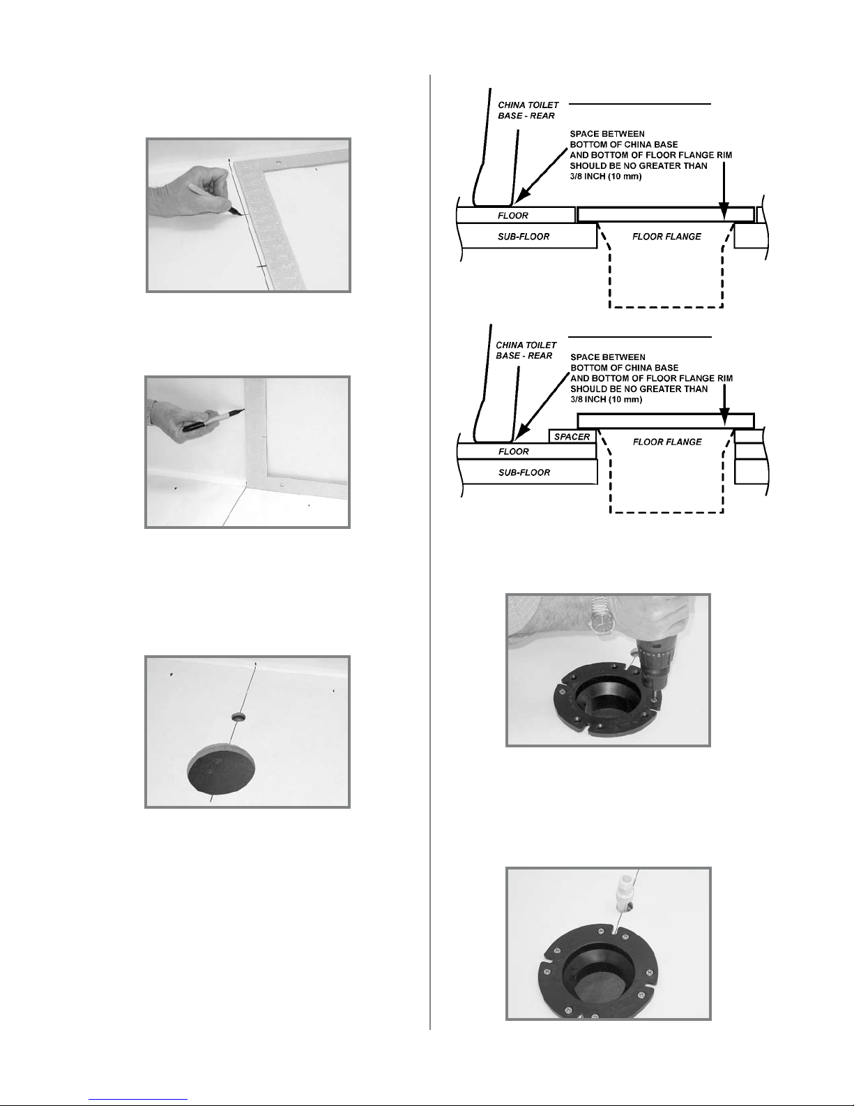
STEP 6: Make a 4-3/4 inch (121 mm) diameter hole (for
most oor anges) or a 5-1/8 inch (130 mm) diameter
hole (for swivel joint oor ange) at the centerline mark
furthest from the wall. Make a 1 inch (25 mm) hole at the
mark closer to the wall for the water line and electrical
wires (g. 6).
Above-Floor Installation
STEP 7: Insert oor ange into larger hole and secure
to the oor with #12x3/4-inch long at head wood or
sheet metal screws (g.7).
IMPORTANT: The prefered oor ange installation
method is to mount the oor fIange directly on the
nished oor. However, if the bottom of oor ange
and bottom of ceramic toilet must be mounted at
different heights, the oor ange must be mounted
within 3/8 inch (10 mm) of the bottom of the toilet (see
illustrations in next column) or leakage may result.
Fig. 6
Fig. 7
STEP 8: Route 1/2-inch (13mm) PEX tubing through
the smaller hole and install a PEX 1/2-inch MPT tting
(g. 8).
NOTE: A water shut-off valve should be installed in the
water line to the toilet for maintenance requirements.
Fig. 8
4
FOR MODEL 3400 TOILET
WITH REMOTE SWITC H
OPERATION, see page 7
for wall switch installation
instructions.
IMPORTANT: If replacing an existing toilet that uses
a 2-bolt oor ange, drill two 5/16-inch dia. holes in
old oor ange that align with two additional holes
in oor ange adapter. Use two #10 or 12 x 1-1/2-inch
wood screws and washers for these drilled holes,
and two T-bolts with at washers and nuts to fasten
ange gasket and oor ange adapter to old oor
ange. Do not use old hardware or seal.
STEP 9: WITH THE ELECTRICAL POWER OFF, route
#14 gauge stranded copper wire from 12 VDC ground
and positive 12 VDC from the fuse panel through a 7- or
8-amp fuse or circuit breaker. Leave at least 30 inches
(762 mm) of wire for connecting to toilet (g. 9).
Fig. 9
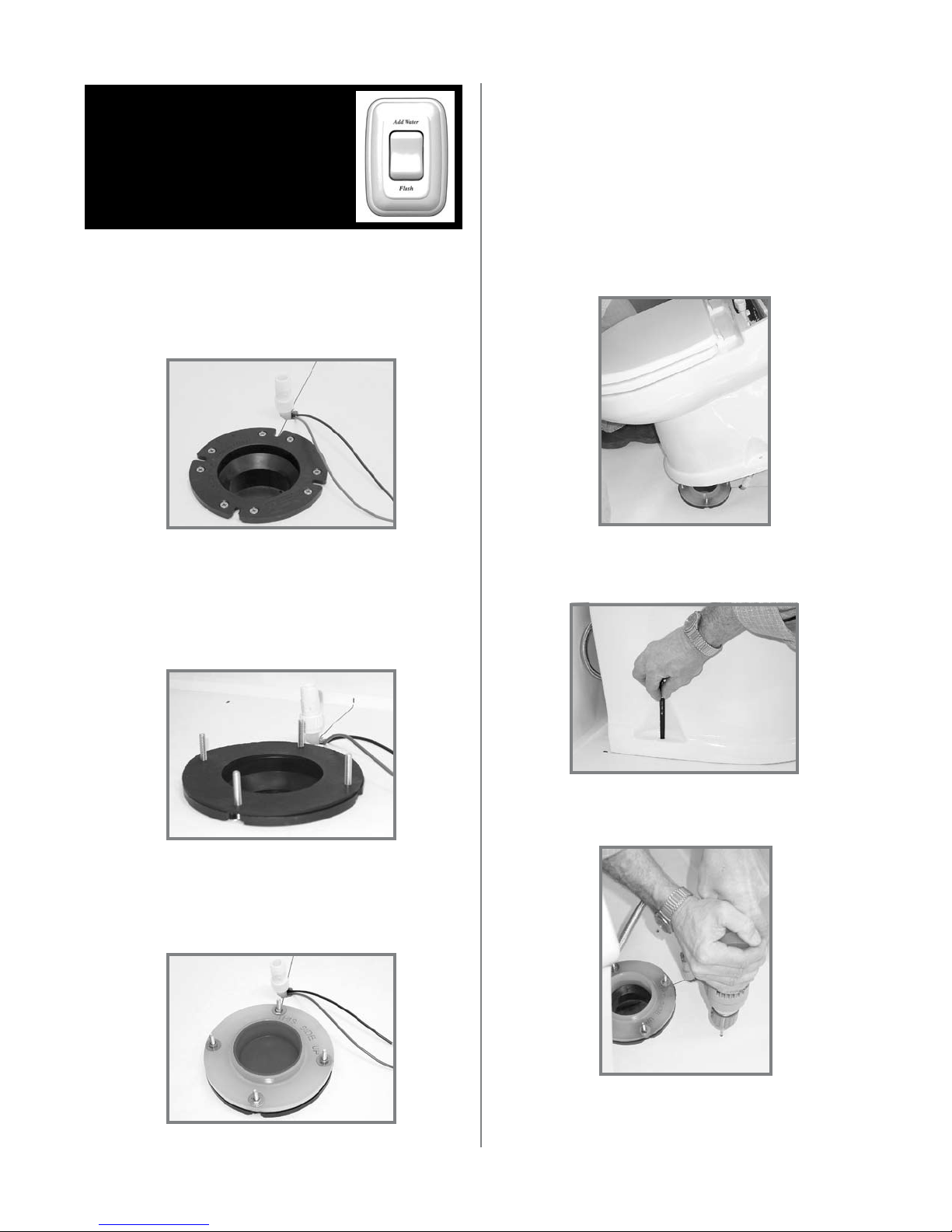
STEP 10: Connect the holding tank to the bottom of the
discharge ange.
STEP 11: Slide the four T-bolts into the slots of the oor
ange. Install the ange gasket over the T-bolts (g.
10).
Fig. 10
STEP 13: Temporarily set the toilet in place on the oor
ange (g. 14).
Fig. 14
STEP 14: Mark the holes for the two toilet mounting
bolts (g. 15).
STEP 12: Install oor ange adapter with words “THIS SIDE
UP” facing up. Tighten adapter to oor ange using four
at washers and hex nuts. Tighten in criss-cross pattern
(g. 11).
Fig. 15
STEP 15: Pick up toilet and set aside. Drill 3/16-inch
pilot holes in the oor (g. 16).
Fig. 11
Fig. 16
5
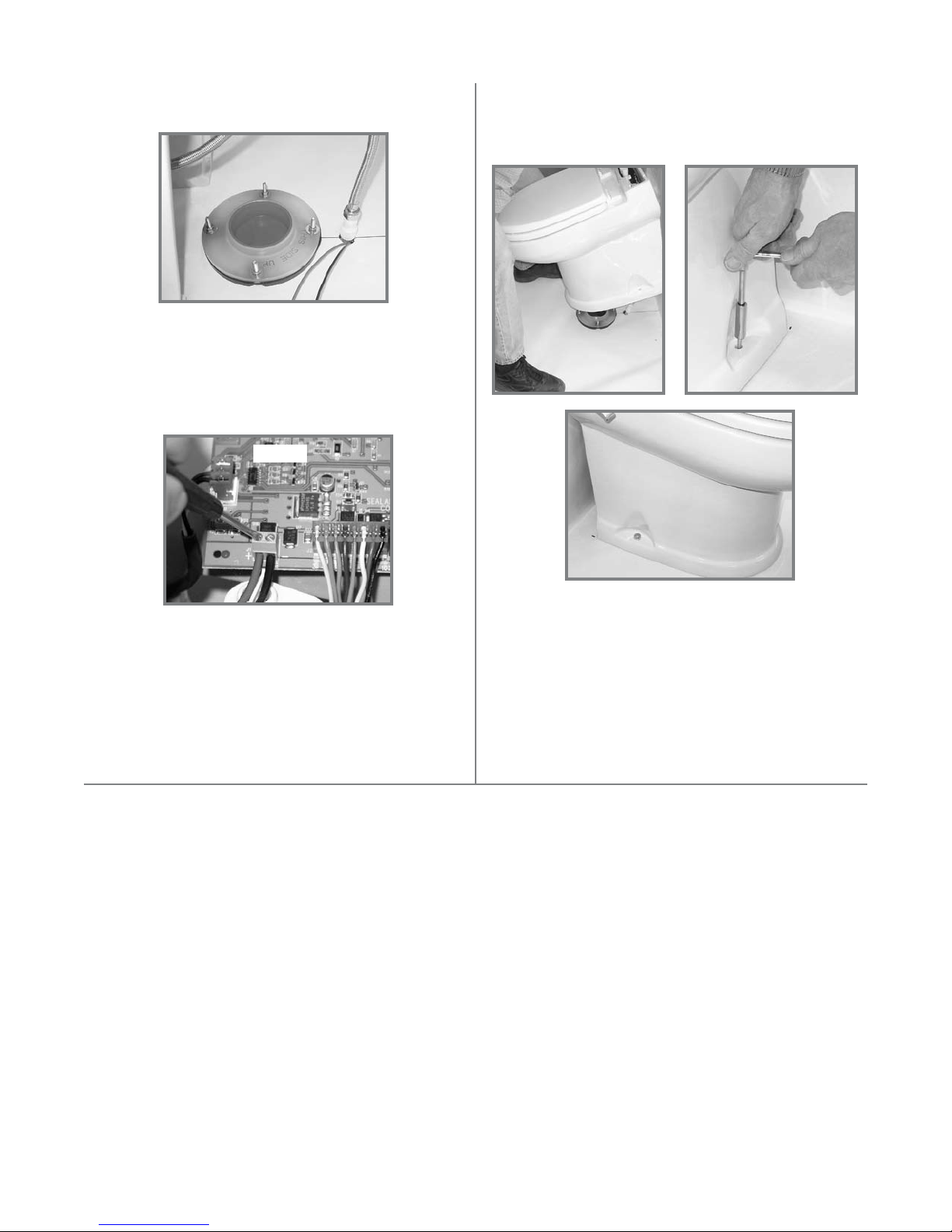
STEP 16: With toilet close to oor ange, connect exible water supply hose to the water line tting (g. 17).
Fig. 17
STEP 17: Insert the positive (+) 12 VDC wire into
position 1 of the green terminal block and tighten the
screw securely. Insert the negative (-) 12 VDC wire into
position 2 of the green terminal block and tighten the
screw securely (g. 18).
Fig. 18
STEP 19: Set the toilet in place (g. 19) and secure to
oor with the #14x2-1/2 inch long lag bolts (g. 20). Install
decorative bolt caps by pushing them onto bolt heads
(g. 21).
Fig. 20Fig. 19
ST E P 18: REMOVE RED CAP FROM MIDDLE
OF FLANGE ADAPTER BEFORE FINAL TOILET
INSTALLATION.
IMPORTANT – DO NOT ATTEMPT TO SLIDE THE
TOILET OVER THE FLANGE ADAPTER. THE
TOILET MUST BE SET DOWN OVER THE ADAPTER TO PREVENT POSSIBLE DAMAGE.
Fig. 21
STEP 20: Place the rear access cover on the back of the
toilet. Press down rmly to seat the fastening strips.
STEP 21: Turn on electrical power and water to toilet.
Lift ush handle and ll toilet bowl with water. Wait one
hour, then inspect the oor around and under the rear of
the toilet for leaks or dampness.
If no leaks are present, toilet is ready for operation.
6
 Loading...