

Page 1
®
SeaLand
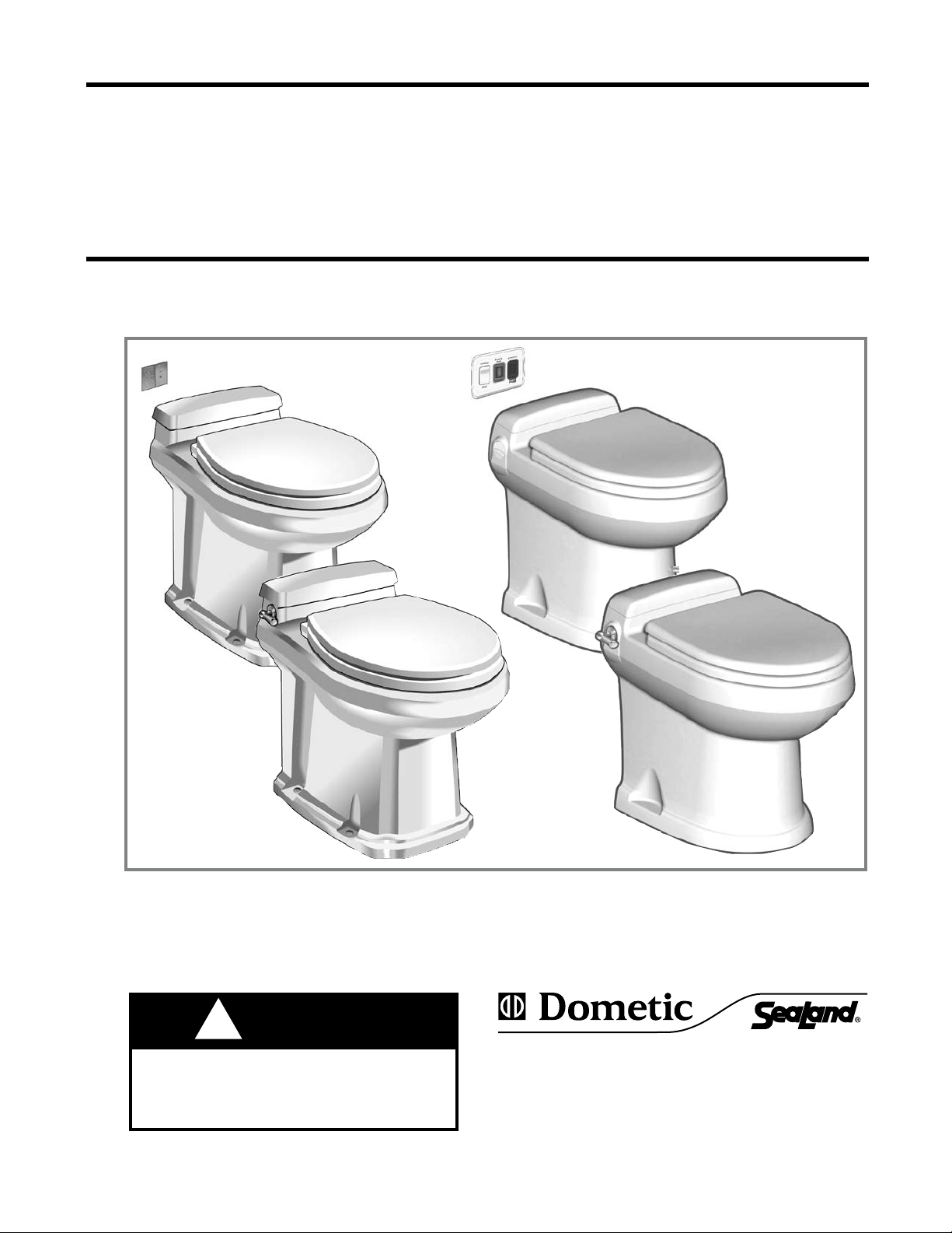
ALL-CERAMIC VACUUM TOILET
OWNER’S MANUAL
VacuFlush® 3000, 3100, 3300, 3400 Series Toilets
3100 Series
3000 Series
IMPORTANT NOTICE
VacuFlush sanitation systems must be installed according to Dometic’s recommended
procedures. Do not attempt installation without rst contacting a VacuFlush Certied
Dealer, your nearest VacuFlush Parts Distributor, or Dometic.
3300 Series
3400 Series
WARNING
!
WARNING
This manual must be read and understood
before adjustment, maintenance, or service
is performed. Modication of this product
can result in property damage.
Dometic Sanitation Corporation
13128 State Rt 226, PO Box 38
Big Prairie, OH 44611
SeaLand Product Customer Service: 1-800-321-9886
(8:00 a.m. - 5:00 p.m. ET)
1
Page 2
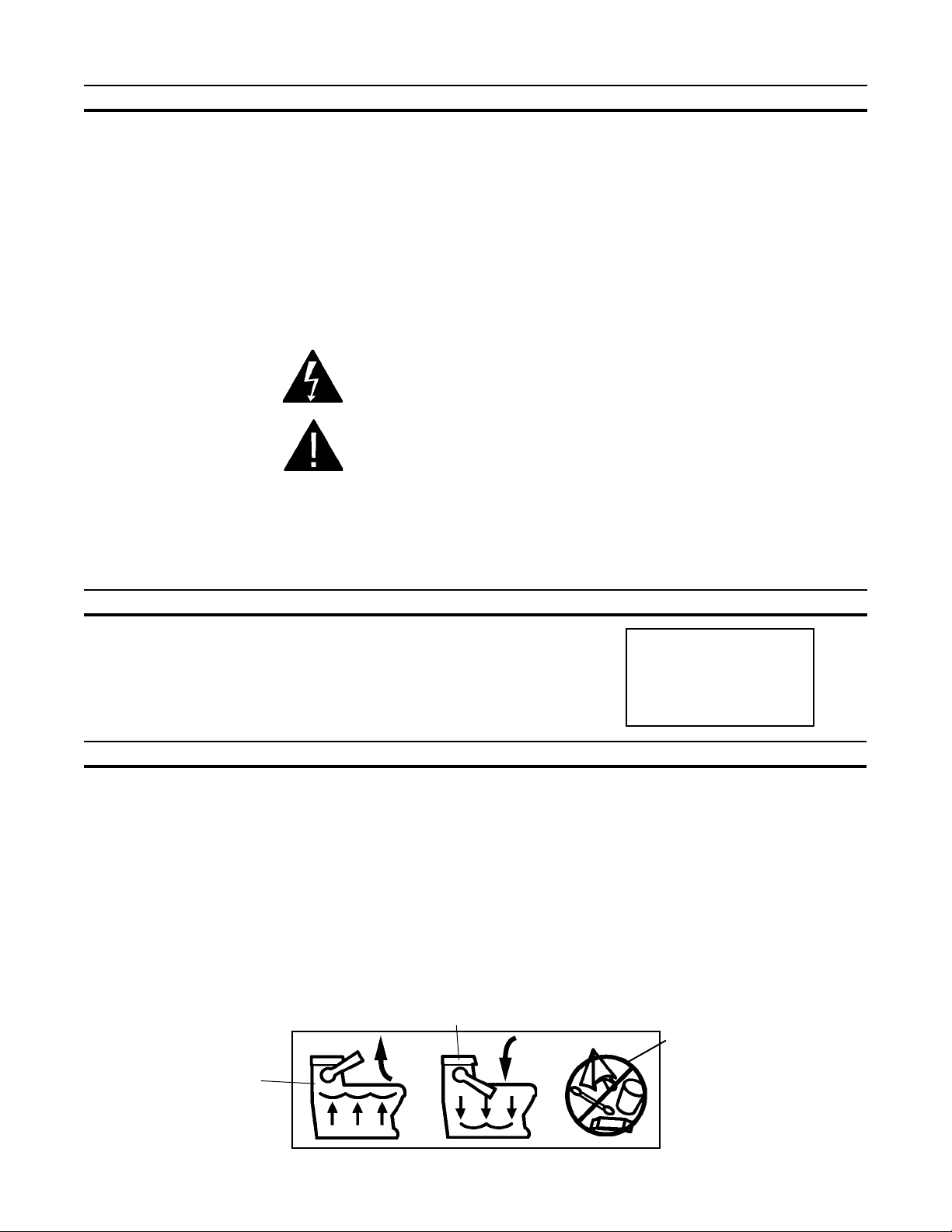
TABLE OF CONTENTS
Toilet Model Identication . . . . . . . . . . . . . . . . . 2
Important Information Before Operation . . . . . . 2
Operating Instructions . . . . . . . . . . . . . . . . . . . . 3
Flush Operation Timing Chart . . . . . . . . . . . . . . 4
Cleaning – Toilet Bowl and Seal . . . . . . . . . . . . 4
Winterizing . . . . . . . . . . . . . . . . . . . . . . . . . . . . 4
Clearing Discharge Lines . . . . . . . . . . . . . . . . . 5
Maintenance Schedule . . . . . . . . . . . . . . . . . . . 5
Spare Parts . . . . . . . . . . . . . . . . . . . . . . . . . . . . 5
Ordering Parts . . . . . . . . . . . . . . . . . . . . . . . . . . 5
Sanitation System Components . . . . . . . . . 6 – 7
Deodorants and Special Tissue . . . . . . . . . . . . 8
Marine Sanitation Regulations . . . . . . . . . . . . . 8
Flush Mechanism Components . . . . . . . . . . . . . 9
Manual Flush Operations . . . . . . . . . . . . . . . . 10
Electrical Specications . . . . . . . . . . . . . . . . . . 10
Troubleshooting . . . . . . . . . . . . . . . . . . . . .11 – 14
RV Wiring Diagrams . . . . . . . . . . . . . . . . 15 – 16
Marine Wiring Diagrams . . . . . . . . . . . . . 17 – 21
Dimensions . . . . . . . . . . . . . . . . . . . . . . . . . . . 21
Customer Service . . . . . . . . . . . . . . . . . . . . . . 22
WarrantY . . . . . . . . . . . . . . . . . . . . . . . . . . . . . 24
WARNING – ELECTRICAL SYSTEM.
Turn off electrical power before servicing.
WARNING – MOTOR STARTS AUTOMATICALLY.
Turn off electrical power before servicing.
CAUTION – System may contain vacuum after shut-down.
Read and understand the complete contents of this manual before operating or servicing the sanitation
system. Failure to follow any precautions may result in damage to the sanitation system.
TOILET MODEL IDENTIFICATION
The model identication label is located on the inside wall of the toilet under
the tank access cover. It will show the model number and serial number.
DOMETIC CORPORATION
P.O. BOX 38, 13128 STATE RT 226 (800) 321-9886
BIG PRAIRIE, OH 44611 USA
MODEL NO. 000
SERIAL NUMBER
000000
IMPORTANT INFORMATION BEFORE OPERATION
1. Fill freshwater tank and add deodorant to holding tank through toilet bowl.
2. Make sure all guests understand toilet operation and that the ushing instruction label is easy for guests to read.
This label (see below) is located under the seat, and is easily seen when the seat is raised.
3. Remember, the vacuum pump starts automatically. Shut off the toilet system before servicing and do not leave the
boat with toilet system breaker on.
4. Never use drain openers, alcohol, solvents, etc. in the system.
5. If the system does not function properly, refer to the Troubleshooting section of this manual and repair as
necessary. If problem persists, contact your local SeaLand dealer or see the Customer Service section of this
manual.
1. To a dd wa ter to bowl before
using (if necessary), raise ush
handle until desired water
level is reached. (Water
ow will stop automatically
after a period of time).
To ush, press ush handle down. Water
2.
will ow into bowl for two seconds, then
ush ball will open. Toilet will not ush
again until “OK to Flush” light is on.
3. Do not di spose of s anita ry
napkins or other non-dissolving
items in toilet, such as facial
tissue or paper towels.
These items can cause
plugging of the sanitation
system.
2
Page 3
OPERATING INSTRUCTIONS
1. Adding More Water To Toilet Bowl
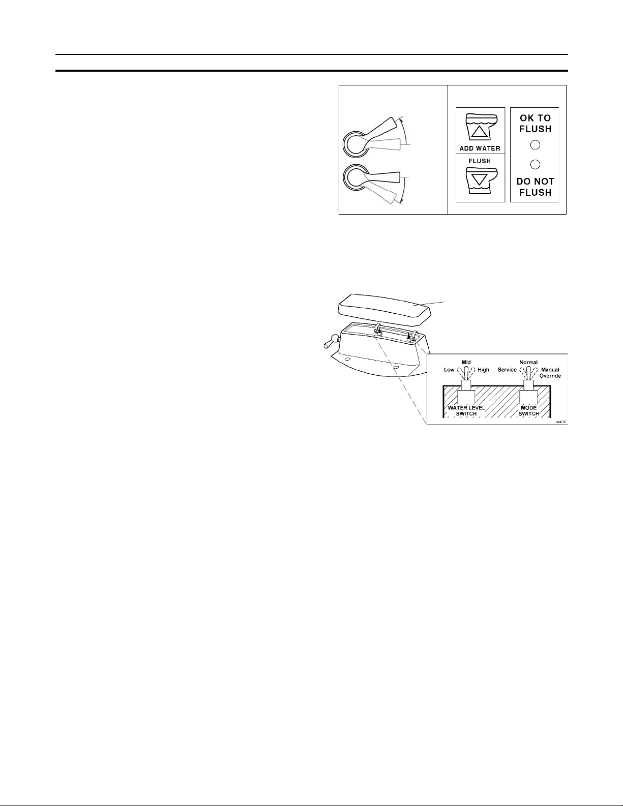
Raise ush handle or press “Add Water” switch until desired
water level is attained. To prevent toilet overow, the control
module limits the amount of water that can be added.
2. Flushing The Toilet
FLUSH HANDLE
ADD WATER
TO BOWL
OFF
REMOTE
SWITCH
STATUS
PANEL
When the vacuum status panel’s green “OK to Flush” light is
on, and the red “Do Not Flush” light is off, press the handle
or “Flush” switch down for a moment, then release it. Holding
OFF
the handle down will not prolong the ush cycle nor start a
new ush cycle. The handle must be allowed to return to the
FLUSH
See page 6 for all VacuFlush wall switches.
“off” position and the vacuum must be allowed to recharge
before another ush cycle can be initiated. A full holding tank will also prevent the toilet from ushing.
3. Selecting Automatic Water Rell Levels:
The Water Level switch is located under the access cover. Carefully lift up on the front of the cover to access the
Water Level switch. There are three water rell levels available. The microprocessor-controlled water valve will
rell the toilet bowl according to your water level selection.
To reinstall the access cover, set the cover on top of the
ACCESS COVER
toilet and press down. This will lock the cover in place
and prevent it from coming loose during travel.
LOW Level
CONTROL SWITCHES
Use this setting to conserve water. This position
reduces the chance of water splashing out of the bowl
during rough travel. If more water is needed for ushing,
lift up on the ush handle. Water ow will stop after
nine seconds to prevent overow.
MID Level
Use this position to keep the toilet bowl clean, especially when family and friends may be using the toilet.
If more water is needed for ushing, raising the ush handle will provide up to six seconds of rell time.
HIGH Level
Use this position if the MID level does not provide a clean toilet bowl. This position is not recommended while
underway. If more water is still desirable for ushing, raising the ush handle will provide up to three seconds
of additional water rell time.
4. Mode Switch
The Mode switch is located on the right side of the control module. It switches between three function settings:
NORMAL
Use this setting for ushing the toilet.
SERVICE
Use this position for cleaning the toilet bowl and ush ball seal. The ush ball will open automatically and remain
open in this position. Lifting up the ush handle provides water.
MANUAL OVERRIDE
Use this position to ush the toilet manually in the event of power or battery failure. This switch disconnects the
electronic brake in the ush valve motor, and allows manual ushing via the override access hole in the side
of the vitreous china base.
Note: The control module allows 15 seconds of water for cleaning. If more water is required, return
the switch to the NORMAL position then back to the SERVICE position.
A safety circuit in the control module monitors ush ball operation. If foreign objects or low voltage prevent
the ush ball from closing, this circuit prevents personal injury or damage to the ush valve motor. If this
condition occurs, reset the control module by placing the Mode switch into the SERVICE position temporarily,
then returning it to the NORMAL position.
3
Page 4

Page 5
CLEARING DISCHARGE LINES
Sanitation hoses should be cleared if toilet will not be needed for an extended period of time (more than two weeks).
1. Fill toilet bowl with water and add 4 oz. (120 ml) of biodegradable laundry detergent (should
NOT contain bleach).
2. Flush toilet, holding pedal down for about two minutes. Close ush ball.
3. Turn off water supply to toilet.
4. Flush the toilet without water, allowing the vacuum pump to shut off after the ush. Repeat three times. (This proce
-
dure will minimize any remaining water in the sanitation hoses.)
5. Turn off power to the vacuum pump.
6. Completely pump out holding tank.
If system will be subjected to freezing temperatures, please follow above procedure, then winterize system as described
in this manual.
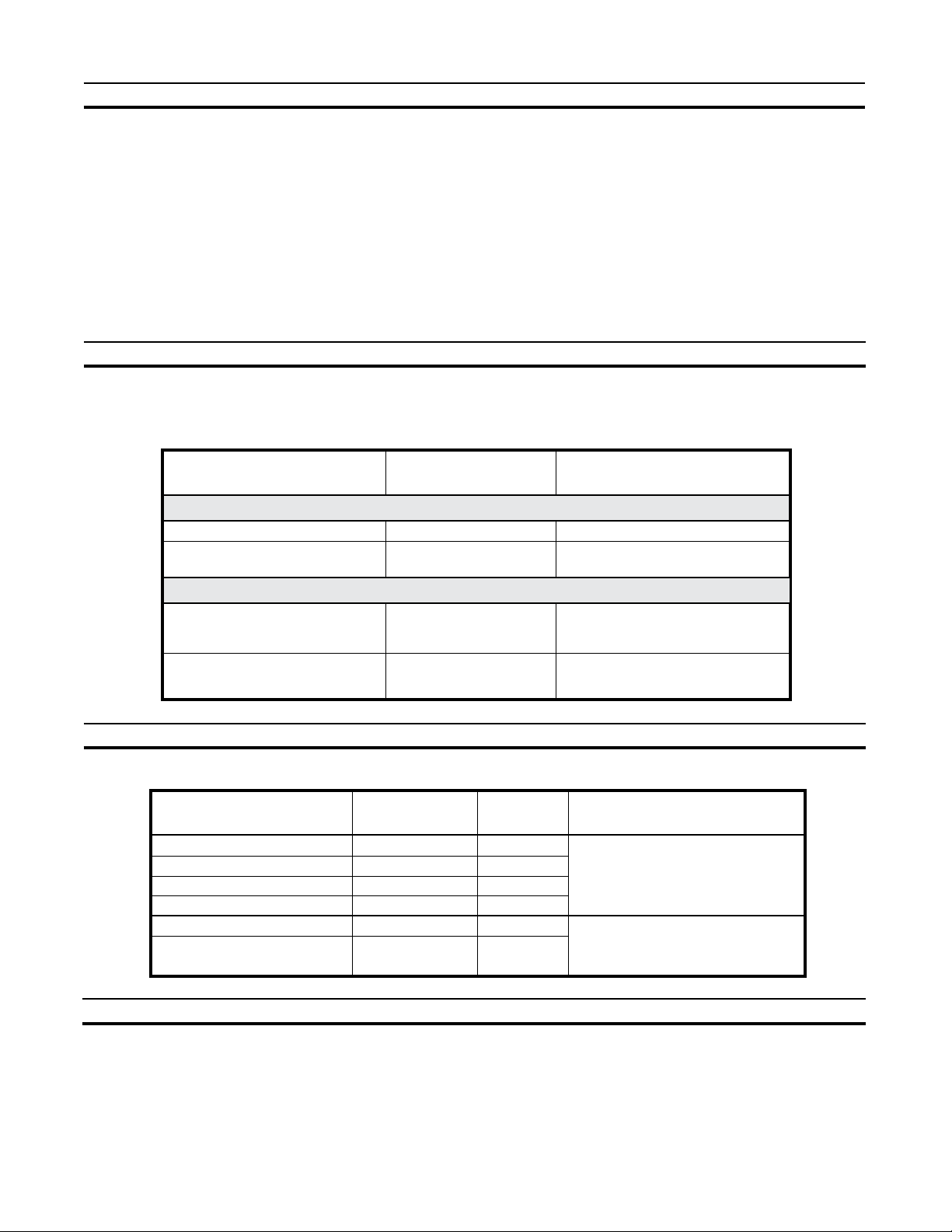
MAINTENANCE SCHEDULE
Maintenance intervals and normal parts replacement vary widely depending on numerous factors such as frequency
of system use, quality of ushing water, etc. The following chart is intended strictly as a general guide in keeping
the sanitation system 100% ready for any conditions of use.
Maintenance Procedure
Recommended
Date of Service
ROUTINE MAINTENANCE
Toilet ush ball seal cleaning
Tighten toilet seat mounting
hardware
Monthly
Monthly (or as needed)
MAJOR SYSTEM MAINTENANCE
Replace duckbill valves in Vacuum
Pump or Vacuum Generator
Replace ush ball seal and ush
ball (if needed)
Every three years
Every three years
SPARE PARTS
The following parts should be kept available at all times:
Description
Flush Ball Seal
Flush Ball
Water Valve
Vacuum Breaker Kit
Vacuum Switch Kit
1.5-inch Duckbill Valve Kit
(2 ea. per kit)
Part Number
see parts list
see parts list
see parts list
see parts list
see parts list
see parts list
Parts Required
SeaLand Bowl and Seal Cleaner
N/A
Duckbill Valve Kit
Flush Ball Seal
Flush Ball
Quantity Where Used
1
1
1
1
1
1
All-ceramic toilet
Vacuum generating system
ORDERING PARTS
Dometic is ready to assist you in the event service is required. Before calling, please have the following information
available. Your cooperation in having this information ready is appreciated and allows us to better meet your needs.
Please refer to the Parts Distributor list in the Customer Service section (page 22).
1. Toilet Model Number
2. Serial Number
3. Part Number, Description and Quantity (see parts list insert)
5
Page 6
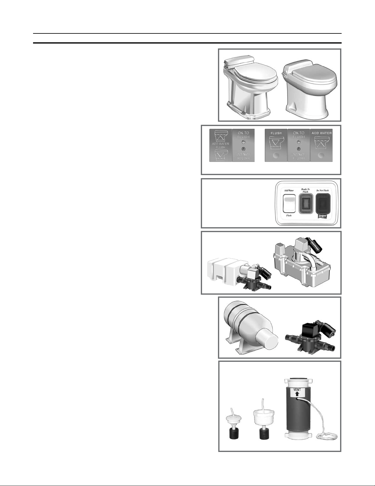
SANITATION SYSTEM COMPONENTS
Vacuum Toilet: VacuFlush all-ceramic vacuum toilets with
Flush and Forget® technology operate differently compared
to other toilets. The vacuum system uses a small amount of
water (a little more than a pint or .5 liter) per ush in addition
to a simple vacuum. The toilet is connected to a pressurized
freshwater system. Fresh water is the key to an odor-free
bat hroom co mpar tment . Most VacuFlush toilets are
equipped with an integral vacuum breaker which prevents
the possible contamination of the freshwater supply.
Flush/Add Water Switches (3100, 3400 models only):
Wall-mounted push-button switches provide electronic
operation of ushing and adding water to the toilet bowl.
Models include two-light vacuum status panel indicating the
toilet is “OK to Flush” or “Do Not Flush”. Models vary.
Vacuum Generator: The vacuum generator combines
the vacuum tank and vacuum pump in one unit. It greatly
reduces installation time and eliminates the hose run
between the tank and pump. Their compact size makes them
especially well-suited to smaller installation spaces.
Vacuum Tank: The vacuum tank stores vacuum energy.
System vacuum level is monitored by a vacuum switch
located on the vacuum tank. When this switch senses
a drop in vacuum in the system, it automatically signals
the pump to energize and bring the vacuum to operating
level. This process is normally completed in less than one
minute.
Vacuum Toilets
Vimar Gewiss
Marine Flush/Add Water Switches
RV Flush/Add Water
Switch
Vacuum
Generators
Vacuum Pump: The vacuum pump is an electric,
straight-through bellows type. It is manufactured of longlasting polypropylene and draws only 4 to 6 amps of current
at 12 VDC. This unique pump design is both an efcient air
and liquid pump that handles solids without a problem. It
has two duckbill valves on each side of the pump chamber
to maintain vacuum and prevent backow of waste.
“Tank Full” Shut-Down Switches (RV option only):
These “Tank Full” micro-oat switches shut down the
vacuum generator when the waste holding tank is full.
We offer three styles to accommodate various installation
requirements.
Sealing grommet style – Item number 900101
MPT style – Item number 900100
Vent style – Item number 900102
(NOTE: Requires relay mounted on vacuum generator.)
Vacuum Tank and
Vacuum Pump
RV “Tank Full” Shut-Down Switches
Sealing
grommet
style
MPT
style
Vent style
6
Page 7
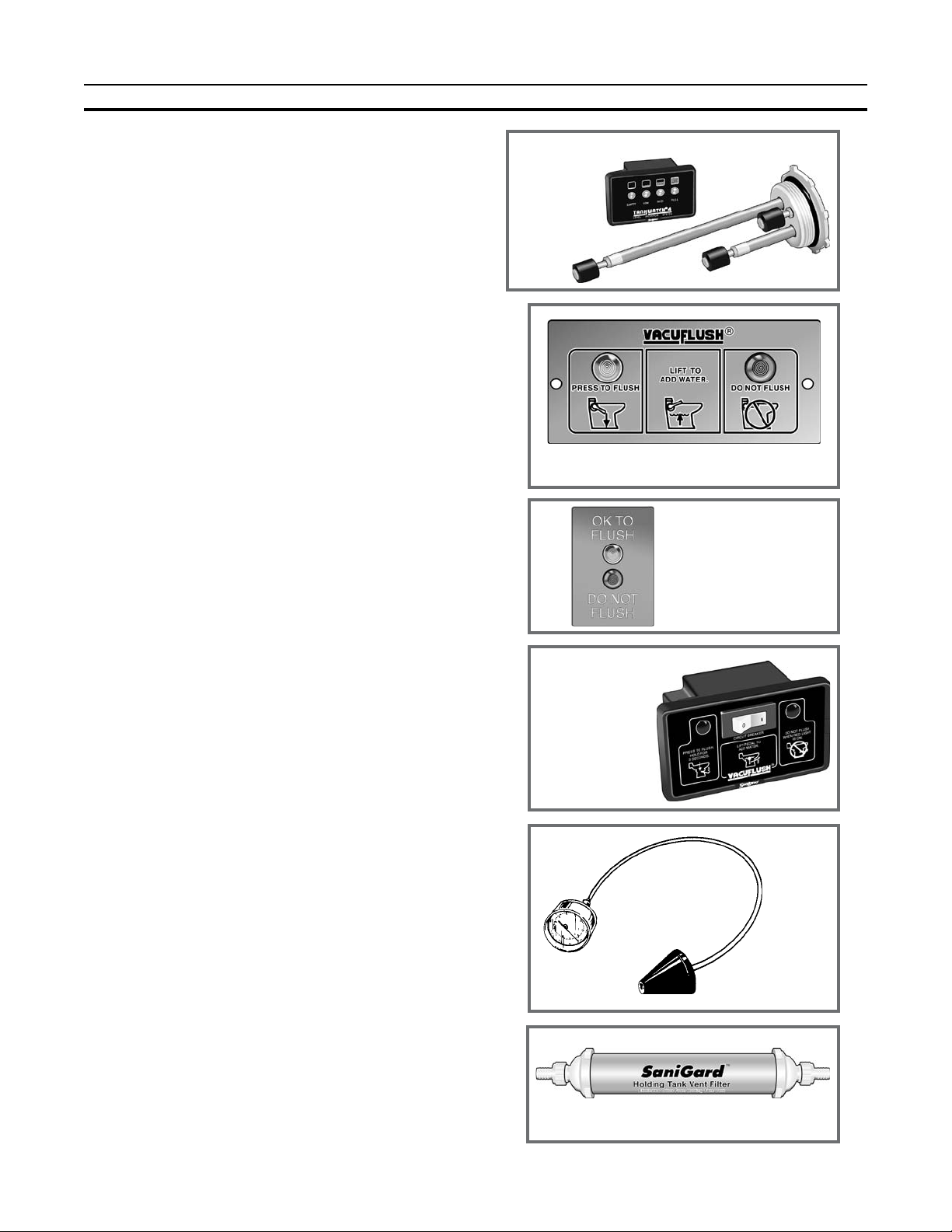
SANITATION SYSTEM COMPONENTS (cont’d)
Tank Watc h
®
Level Indicator (marine option only):
The TankWatch unit utilizes micro-oat switches which
activate an indicator panel. The micro-oat switches are
installed in the top of the holding tank. The adjustable
probe assemblies are exible polybutylene tubing and are
designed to ex when tank contents move.
VacuStat™ Indi cat or Pa nel: Co nti nuously mo ni-
tors v a cuum s t atus fo r prope r t oilet o p erati o n .
Brus h e d meta l l ic fini s h compl e m ents b a t hroom
decor. Item number 700112 (12VDC).
Vacuum Status Panel (optional): A two-light status panel
indicates the system is “OK to Flush” or “Do Not Flush”.
The green “OK to Flush” light is illuminated when there is
adequate vacuum pressure available and when the holding
tank is less than full. Item number 710012.
VacuFlush Status Panel (optional): Includes two-light
status panel indicating the system is “OK to Flush” or “Do
Not Flush”, and circuit breaker to shut down system at night.
Item number 500012 (12 VDC) or 500024 (24 VDC).
Vacuum Generator Shut-down Relay (standard on RVs;
marine option): This relay can automatically shut down
power to the VacuFlush toilet system to prevent overlling of the holding tank. Item number 310289 (12 VDC) or
310290 (24 VDC).
Vacuum Tester (optional): This tool assists in identifying
the location of vacuum leaks. The vacuum tester consists
of a vacuum gauge and a cone-shaped plug. Inserting the
plug in the inlet of the vacuum tank or vacuum generator
isolates the toilet from the system. In this way, a vacuum
leak can easily be located in either system. Item number
530002.
In-Line Vent Filter (marine option only): The SaniGardTM
vent lter has special odor-removing lter materials to help
keep your vehicle smelling clean and pleasant. Heavierthan-air malodors accumulate in the holding tank. This vent
lter has a special type of activated lter media to remove
these odors before they offend. Each cartridge is good for
an entire season, and is easily replaced for a fresh start.
Replacement cartridges are available.
Holding Tanks (marine option only – not shown):
SeaLand holding tanks are made of super-strong, 3/8”
(10mm) thick polyethylene — 50% thicker than most other
holding tanks. Each features solid, one-piece construction
with no seams for unmatched durability. A deodorant additive is recommended to keep the holding tank odor-free.
See Deodorants and Special Tissue section for further
information (page 8).
TankWatch
Panel and
Probes
VacuStat Indicator Panel
Vacuum
Status Panel
VacuFlush
Status Panel
Vacuum Tester
Vent Filter
7
Page 8

MARINE SANITATION REGULATIONS
All boats with xed toilets in U.S. waters and in the waters of some other countries are required to be equipped with an operable
marine sanitation device (MSD). The VacuFlush vacuum sanitation system, when installed in a boat, is a holding tank or Type
III system as dened by the U.S. Coast Guard. Type III systems are designed to permit operation of the toilet without the direct
discharge of untreated waste after every ush. This means onboard toilet facilities can be used when the boat is near swimmers,
beaches or shellsh beds.
Type III systems can be discharged at marina dockside pump-out stations or, if in coastal waters, a minimum of three miles
offshore. Overboard discharge capability must remain secured while within the three-mile limit. The overboard discharge
pump is activated Mswicd ocated in0thetoiletcumxamtmenu.
8
Page 9

FLUSH MECHANISM COMPONENTS
1. To a c cess
base assembly
c o m p on ent s ,
remove decora-
tive screw caps
and unscrew the
bolts that hold
ch ina to ilet to
oor.
2. Remove access cover.
Lift up control module. Disconnect power cable and
vacuum control cable from
co ntr ol modu le. Do n ot
di sconnec t flu sh handle
ca bl e or base asse mb ly
cable.
REMOTE FLUSH SWITCHES (3100, 3400 toilets)
Vimar switch - marine Gewiss switch - marine RV ush switch
FLUSH HANDLE (3000, 3300 toilets)
(under Access Cover)
Flush
Handle
Flush
Switch
Flush
Handle
Cable
BASE ASSEMBLY COMPONENTS
(under china toilet)
Input
for
Flush
Switch
Cable
Input
for
Vacuum
Control
Cable
3. Lif t ch in a toile t
straight up and set it
down close to front of
oor ange/adapter
assembly. Turn off
water to toilet and
disconnect flexible
water line at rear of
base assembly. The
toilet is completely
disconnected.
CONTROL MODULE
Water
Level Switch
Mode
Switch
Water Valve
Flush Valve
Motor
Motor
Drive Arm
Base Assembly
Cable
Flush Ball
Rotor Arm
Discharge Adapter
(3006, 3009, 3106, 3109,
3309, 3409)
Discharge Adapter
(3048, 3148, 3348,
3448)
Open Limit
Switch
Closed Limit
Switch
Flexible Water Supply Hose
Power
Cable
Input for
Base Assembly
Cable
9
Page 10

MANUAL FLUSH OPERATION
In the event of an electrical failure, the ush ball can be manually operated to clear the bowl. We recommend using
a long-neck screwdriver or 7/16-in. socket for the operation shown below. NEVER PRY OPEN THE FLUSH BALL
FROM INSIDE THE TOILET BOWL. Damage to the ush ball and bowl seals may result.
1. Remove PC board
access cover. Place
Mode Switch in the
“Manual Override” position. This disconnects
ush valve motor brake
from electrical circuit.
2. Locate hole on left side
of china toilet. This allows access to the ush
valve motor drive arm.
Manual Override
position
3. Insert screwdriver or
7/16-in. socket through
access hole and onto hex
head.
4. Turn screwdriver or
socket wrench counter-
clockwise. This will open
ush ball and allow bowl
contents to clear. After
bowl is clear, turn screwdriver or socket wrench clockwise
to return ush ball to original position.
NOTES:
Water will not enter the toilet bowl during manual ush
operation.
Place Mode Switch in the “Normal” position before
returning to automatic operation.
TOILET SYSTEM ELECTRICAL SPECIFICATIONS
12VDC 24VDC
Maximum standby current (amps): .080 .080
Maximum operating current (amps): 6.5 2.5
Flush motor locked rotor current (amps): 14.5 7.25
Maximum voltage 15 30
Minimum voltage: 10 20
Input power wire size 14 ga. 14 ga.
All other wires size: 18 ga. 18 ga.
Fuse size (amps) 8 4
NOTES: Standby current includes ush panel status light.
Operating current does not include vacuum pump or other sanitation system components.
10
Page 11

TROUBLESHOOTING
A volt/ohmmeter (VOM) and the appropriate Toilet Wiring Diagram may be required for this section.
Caution: Portions of this section will require that power be applied to the toilet. Keep hands away from
the ush ball, motor drive arm and rotor shaft to prevent personal injury during testing and troubleshooting.
The control module uses a microprocessor to provide all the automatic and timing functions. The control module
is on the right side under the access cover on the top of the toilet. The control module has input and output status
lights that can be used in troubleshooting the toilet.
The program in the microprocessor monitors the input and output signals during a normal ush cycle. If the inputs
or outputs do not follow the commands of the program, then the microprocessor may go into a “standby” mode and
ash an “error code.” The microprocessor is reset by placing the Mode switch in the SERVICE position temporarily,
then returning the switch to the NORMAL position.
A safety circuit in the control module monitors ush ball operation. If foreign objects or low voltage prevent the ush
ball from closing, this circuit prevents personal injury or damage to the ush valve motor. If this condition occurs,
reset the control module by placing the Mode switch into the SERVICE position temporarily, then returning it to the
NORMAL position.
Status Light
1 Low Level
2 High Level
3 Valve Closed
4 Valve Open
5 Service Mode
6 Flush
7 Add Water
8 High Vac Switch
9 Holding Tank Full
10 OK to Flush
11 Do Not Flush
12 Water Valve
13 +5V
ERROR CODES
Status Light
No. of Flashes
10 OK to Flush
11 Do Not Flush
11 Do Not Flush
11 Do Not Flush
11 Do Not Flush
Function
Water Level Switch in “Low” position.
Water Level Switch in “High” position.
Flush valve Closed Limit Switch engaged.
Flush valve Open Limit Switch engaged.
Mode Switch in “Service” position.
Flush Switch on control panel engaged.
Add Water Switch on control panel engaged.
High vacuum in system (allows toilet to ush).
Full holding tank (prevents toilet from ushing).
Signal to “OK TO FLUSH” light on control panel.
Signal to “DO NOT FLUSH” light on control panel.
Electric water valve energized.
Input power present.
Pause
1
1
2
3
4
.5 sec.
2 sec.
2 sec.
2 sec.
2 sec.
Condition
Mode Switch in SERVICE position
VALVE OPEN Limit Switch problem
VALVE CLOSED Limit Switch problem
Insufcient vacuum in system
Flush valve motor relay failure
LED 1
LO LEVEL
LED 2
HI LEVEL
LED 3
VALVE CLOSED
CONTROL MODULE STATUS LIGHTS
LED 4
VALVE OPEN
LED 5
SERVICE MODE
FLUSH
LED 6
ADD WATER
LED 7
LED 8
HI VAC SWITCH
LED 9
HOLD TANK FULL
11
LED 10
OK TO FLUSH
LED 11
DO NOT FLUSH
WATER VALVE
LED 12
LED 13
+5V
Page 12

TROUBLESHOOTING (cont’d)
ERROR CODE CORRECTIVE PROCEDURES
Condition
Mode Switch in SERVICE position.
Valve Open Limit Switch problem.
Valve Closed Limit Switch problem.
Insufcient vacuum in system.
Flush valve motor relay failure.
Corrective Action
Return Mode Switch to NORMAL position.
With the ush valve fully open, check the “VALVE OPEN” status light. If
the light is off, then the Valve Open Limit Switch is out of alignment or
defective, or related wiring is defective.
With ush valve in the fully closed position check the “VALVE CLOSED”
status light. If the light is off, then the Valve Closed Limit Switch is out
of alignment or defective, or related wiring is defective.
Check the “HI VAC” status light. If the light is off, the signal from the vacuum switch located on the vacuum generator or vacuum tank is absent
and preventing the toilet from ushing in the NORMAL mode. Check
for loss of power to the vacuum generator or vacuum pump. Check for
loose or defective wiring between the vacuum switch and the toilet.
Replace control module.
TOILET OPERATION
SYMPTOM 1. Toilet will not ush and water will not enter toilet bowl.
Condition
+5V status light is off (on far
right of control module):
Corrective Action
• Check toilet fuse or circuit breaker at DC distribution panel.
• Check for loose or defective wiring between control module and DC
distribution panel.
• Check for reverse polarity of input power to control module.
• If all of above check OK, replace control module.
+5V status light is on:
• Input power must be 10 volts or higher.
• Check control module for error codes.
• Check “HI VAC” status light. If light is off, vacuum is low, preventing
the toilet from ushing.
• Check “HOLD TANK FULL” status light. If light is on, black water
holding tank is full, preventing toilet from ushing.
• Put Mode Switch in SERVICE position. If ush valve opens, go to
next step. If the ush valve does not open, go to Symptom 2.
• Put the Mode Switch in NORMAL position and push ush handle
down while observing “FLUSH” status light. The “FLUSH” status
light must come on when the handle is pressed and go off when the
handle is released. If the “FLUSH” status light did not follow commands of handle, then ush switch or related wiring is defective.
SYMPTOM 2. Flush valve will not open when the Mode Switch is in the SERVICE position or when
the ush handle is pushed while in the NORMAL position.
Procedure
Check the voltage output
to the ush valve motor at
jack 6, pins 9 and 10 on the
control module as follows:
Corrective Action
• Pull the control module out as far as the control cables will allow.
Locate jack 6 at the bottom of the control module.
• Remove the purple wire from pin 6.
• With DC voltmeter test leads across pins 9 and 10, ip the Mode
Switch between the NORMAL and SERVICE positions. If voltage is
present for about two seconds in the SERVICE position, the ush
valve motor or related wiring is defective. If voltage is not present,
replace the control module.
12
Page 13

TROUBLESHOOTING (cont’d)
SYMPTOM 3. Flush valve will not close.
Condition/Procedure
Mode Switch is in SERVICE
position:
Foreign object prevents the ush
valve from closing and the safety
circuit locked ush valve in open
position:
Check for error code at “DO NOT
FLUSH” status light.
Check the voltage output to
the ush valve motor at jack 6,
pins 9 and 10 on the control
module as follows:
Corrective Action
• Return switch to the “Normal” position.
• Reset the control circuit by putting the Mode Switch in the SERVICE
position temporarily, then returning to the NORMAL position. If the
ush valve did not close, go to next step.
• If showing error, follow the instructions in the Error Code Corrective
Procedures section.
• Pull the control module out as far as the control cables will allow.
Locate jack 6 at the bottom of the control module.
• Remove the green wire from pin 5.
• With DC voltmeter test leads across pins 9 and 10, ip the Mode
Switch between the SERVICE and NORMAL positions. If voltage is
present for about two seconds in the NORMAL position, the ush
valve motor or related wiring is defective.
• If voltage is not present, replace the control module.
SYMPTOM 4. Water will not enter toilet bowl during a ush and when the ush handle is raised
in the “Add Water” position.
Procedure
Place the Water Level switch
in the LOW position. Check
the “WATER VALVE” status
light while pressing the ush
handle down:
Corrective Action
• If the “WATER VALVE” status light comes on, the water valve lter
screen may be plugged with debris, or the water valve or its related
wiring is defective.
• If the “WATER VALVE” status light remains off, replace the control
module.
• If voltage is not present, replace the control module.
SYMPTOM 5. Water will not enter toilet bowl when the ush handle is raised in the “Add Water”
position.
Procedure
Flush the toilet, then place
the Water Level switch in the
LOW position. Then check
the “LO LEVEL” status light
while raising the ush handle:
Corrective Action
• If the “LO LEVEL” status light comes on, replace the control module.
• If the “LO LEVEL” status light does not come on, the ush switch or
its related wiring is defective.
SYMPTOM 6. Water Level switch has no effect on water level in the “Low” or High” position.
Corrective Action
• Replace control module.
SYMPTOM 7. Flush valve will not open when Mode Switch is in the “Service” position but opens
during a normal ush cycle.
Corrective Action
• Replace control module.
13
Page 14

TROUBLESHOOTING (cont’d)
SYMPTOM 8. Water will not stay in bowl and system loses vacuum.
Condition/Procedure
Put Mode Switch in “Service”
position:
Worn or damaged ush valve ball
and seal:
Corrective Action
• Clean underside of ush valve ball seal of dirt and debris.
• Remove toilet from oor and remove base assembly from toilet and
replace ush valve ball and seals.
SYMPTOM 9. Water will not shut off and overows the toilet.
Procedure
Check the “WATER VALVE” status
light:
Corrective Action
• If the light is on when not ushing the toilet or adding water, replace
the control module. If the light responds correctly, go to next step.
• Dirt or debris lodged in the water valve seal. Remove the toilet from
the oor, disassamble and clean water valve.
• Replace water valve.
SYMPTOM 10. Water is leaking from under the toilet.
Procedure
Remove the toilet from the
oor and inspect the following
with both water and electrical
power applied:
(place a container under the base
assembly to catch any water during
the inspection procedure)
• Water hoses and ttings, water valve assembly
• China toilet bowl
• Upper base seal
• Flush valve ball rotor shaft shaft
• Base assembly
SYMPTOM 11. System leaks vacuum, but water remains in toilet bowl.
Procedure
Remove the toilet from the oor
and insert a plug or vacuum tester
into the discharge port of the oor
ange or discharge adapter:
Corrective Action
• If the vacuum leaks stops, go to the next step. If the vacuum leak
continues, the leak is in the discharge plumbing and not the toilet.
• Inspect the O-ring around the bottom of the base. Replace if defec-
tive.
• Inspect the inside surface of the discharge adapter or oor ange for
grooves or scratches that may interfere with the O-ring seal. Replace
if defective.
• If all of above appear normal, then the leak is most likely the rotor
shaft O-rings. Replace the rotor shaft.
14
Page 15

RV WIRING DIAGRAMS
RV VACUFLUSH TOILET – FLUSH HANDLE (3000, 3300 SERIES)
RV VACUFLUSH TOILET – REMOTE FLUSH SWITCH (3100, 3400 SERIES)
REMOTE FLUSH SWITCH
(3100, 3400 series RV toilets)
15
Page 16

RV WIRING DIAGRAMS (cont’d)
RV VACUSTAT PANEL OPTION
RV VACUFLUSH STATUS PANEL OPTION
16
Page 17

MARINE WIRING DIAGRAMS
MARINE VACUFLUSH TOILET – FLUSH HANDLE (3000, 3300 SERIES)
MARINE VACUFLUSH TOILET – GEWISS FLUSH SWITCH (3100, 3400 SERIES)
GEWISS FLUSH SWITCH OPTION
(3100, 3400 series marine toilets)
17
Page 18

MARINE WIRING DIAGRAMS (cont’d)
VIMAR FLUSH SWITCH OPTION
VIMAR FLUSH SWITCH OPTION
(3100, 3400 marine toilets)
MARINE VACUSTAT PANEL OPTION
18
Page 19

MARINE WIRING DIAGRAMS (cont’d)
MARINE VACUFLUSH STATUS PANEL / TANKWATCH OPTION
VACUFLUSH STATUS PANEL OPTION
IMPORTANT: ORANGE WIR E ON PIN 15 OF CONTROL
MODULE MUST BE CONNECTED TO THE “A” TERMINAL OF
THE VACUUM SWITCH REGARDLESS OF WHICH VACUUM
SOURCE IS USED.
19
Page 20

MARINE WIRING DIAGRAMS (cont’d)
VACUUM GENERATOR/VACUUM TANK AND PUMP OPTION
M-SERIES VACUUM PUMP AC CIRCUIT OPTION
20
Page 21

MARINE WIRING DIAGRAMS (cont’d)
M-SERIES VACUUM PUMP DC CIRCUIT OPTION
DIMENSIONS
Models 3006, 3106*
Models 3309, 3348,
3409*, 3448*
Models 3009, 3048,
3109*, 3148*
21
3100 and 3400 series toilets operate
*
with wall-mounted ush switch, and
do not include ush handle on toilet.
China toilet dimensions may vary
±3/8-inch (10mm).
Page 22

CUSTOMER SERVICE
There is a strong, worldwide network to assist in servicing and
maintaining your sanitation system. For the Authorized Service
Center near you, please call from 8:00 a.m. to 5:00 p.m. (ET)
Monday through Friday. You may also write us at Dometic
Corp., P.O. Box 38, Big Prairie Ohio 44611.
Telephone: 1 800-321-9886 U.S.A. and Canada
330-496-3211 International
U.S.A.
MASTER SANITATION
DISTRIBUTORS
U.S.A. – North Central
(IL, IN, KY, MI, OH)
Midwest Marine Supply
24300 Jefferson Ave.
St. Clair Shores, MI 48080
Tel: 586-778-8950
800-860-1540
Fax: 586-778-6108
E-mail: midwestmarine@yahoo.com
U.S.A. - Northeast
(CT, DE, DC, MA, MD, ME, NH, NJ, NY,
PA, RI, VA, VT, WV)
Northeast Marine Sanitation
69 Florida Street
Farmingdale, NY 11735
Tel: 631-752-7606
800-352-4323
Fax: 631-752-7615
888-283-7606
E-mail: info@northeastsanitation.com
U.S.A. - Northwest
(AK, ID, MT, OR, WA, WY)
Marine Sanitation, Inc.
1900 N. Northlake Way, Suite 121
Seattle, WA 98103
Tel: 206-633-1110
800-624-9111
Fax: 206-633-0317
E-mail: marinesan@mindspring.com
U.S.A. - South Central
(AR, KS, LA, MO, MS, NM, OK, TX)
U.S.A. - Southeast
(AL, FL, GA, NC, PR, SC, TN, VI)
Environmental Marine
111 S.W. 23rd Street, Suite A
Fort Lauderdale, FL 33315
Tel: 954-522-2626
800-522-2656
Fax: 954-522-5152
E-mail: info@environmentalmarine.com
U.S.A. - Southwest
(AZ, CO, NV, UT, CA-south)
Ardemco Marine Specialties
778 West 17th Street
Costa Mesa, CA 92627
Tel: 949-722-7672
800-253-0115
Fax: 949-642-9582
E-mail: info@ardemco.com
U.S.A. – Upper Midwest
(IA, MN, NE, ND, SD, WI)
PowerHouse Marine
518 Logan
La Crosse, WI 54603
Tel: 608-784-9580
888-752-4539
Fax: 608-784-8422
E-mail: dave@powerhousemarine.com
U.S.A. – Northern California
Fox Marine
6545 Caballero
Buena Park, CA 90620
Tel: 800-826-2873
Fax: 714-690-1511
E-mail: foxmarco@pacicsupplyco.com
AER Supply
P.O. Box 349
2301 Nasa Road #1
Seabrook, TX 77586
Tel: 281-474-3276
800-767-7606
Fax: 281-474-2714
E-mail: sales@aersupply.com
You may also contact or have your local dealer contact the Parts
Distributor nearest you for quick response to your replacement
parts needs. They carry a complete inventory for the SeaLand
product line.
Fax: 330-496-3097 U.S.A. and Canada
330-496-3220 International
CANADA
MASTER SANITATION
DISTRIBUTORS
Canada - East
Eastern Marine Systems, Inc.
12-A Leslie Street
Toronto, Ontario M4M 3H7
Tel: 416-465-1668
888-764-1111
Fax: 416-465-2098
E-mail: info@eastmar.com
Canada - West
Western Marine Company
1494 Powell Street
Vancouver, BC V5L 5B5
Tel: 604-253-7721
800-663-0600
Fax: 604-253-2656
800-663-6790
E-mail: sales@westernmarine.com
INTERNATIONAL
SEALAND SANITATION SYSTEM
DISTRIBUTORS
Call 1-800-321-9886, email us at
sealand@dometicusa.com, or visit
www.dometic.com for the distributor
nearest you.
22
Page 23

THIS PAGE IS INTENTIONALLY LEFT BLANK.
23
Page 24

MANUFACTURER’S ONE-YEAR LIMITED WARRANTY
Dometic Corporation warrants, to the original purchaser only, that this VacuFlush® vacuum discharge toilet, if used
for personal, family or household-like purposes, and if installed according to Dometic’s recommended procedures,
is free from defects in material and workmanship for a period of one (1) year from the date of purchase.
If this Dometic product is placed in commercial or business use, it will be warranted, to the original purchaser only,
to be free of defects in material and workmanship for a period of ninety (90) days from the date of purchase.
Dometic reserves the right to replace or repair any part of this product that proves, upon inspection by Dometic, to
be defective in material or workmanship. All labor and transportation costs or charges incidental to warranty service
are to be borne by the purchaser-user.
EXCLUSIONS
IN NO EVENT SHALL DOMETIC BE LIABLE FOR INCIDENTAL OR CONSEQUENTIAL DAMAGES, FOR DAMAGES
RESULTING FROM IMPROPER INSTALLATION, OR FOR DAMAGES CAUSED BY NEGLECT, ABUSE, ALTERATION, OR USE OF UNAUTHORIZED COMPONENTS. THIS INCLUDES FAILURES WHICH MAY RESULT FROM
NOT FOLLOWING THE WINTERIZATION OR CLEANING PROCEDURES AS DESCRIBED IN THIS MANUAL. ALL
IMPLIED WARRANTIES, INCLUDING ANY IMPLIED WARRANTY OF MERCHANTABILITY OR FITNESS FOR ANY
PARTICULAR PURPOSE, ARE LIMITED TO A PERIOD OF ONE (1) YEAR FROM DATE OF PURCHASE.
IMPLIED WARRANTIES
No person is authorized to change, add to, or create any warranty or obligation other than that set forth herein.
Implied warranties, including those of merchantability and tness for a particular purpose, are limited to one (1) year
from the date of purchase for products used for personal, family or household-like purposes, and ninety (90) days
from the date of purchase for products placed in commercial or business use.
OTHER RIGHTS
Some states do not allow limitations on the duration of an implied warranty, and some states do not allow exclusions
or limitations regarding incidental or consequential damages; so, the above limitations may not apply to you. This
warranty gives you specic legal rights, and you may have other rights which vary from state to state.
To obtain warranty service, rst contact your local dealer from whom you purchased this product.
SeaLand, VacuFlush, and Flush and Forget are registered trademarks of Dometic Corporation.
Dometic is a customer driven, world-leading provider of innovative leisure
products for the caravan, motorhome and marine markets. Dometic offers
a complete range of air conditioners, refrigerators, awnings, cookers,
sanitation systems, lighting, windows, doors and other equipment that
makes leisure life more comfortable away from home.
Dometic also provides refrigerators for specic use in hotel rooms,
ofces and for storage of medical products and wine. Dometic’s products
are sold in almost 100 countries and are produced mainly in Dometic’s
own production facilities around the world. Dometic has more than
4,400 employees.
600344321 7/06
Dometic Sanitation Corporation
13128 State Rt 226, PO Box 38
Big Prairie, OH 44611
SeaLand Product Customer Service: 1-800-321-9886
(8:00 a.m. - 5:00 p.m. ET)
Email: sealand@dometicusa.com
www.DometicSanitation.com
® Registered; ™ Trademark of Dometic Corporation.
© Dometic Corporation
24
 Loading...