

Page 1
Momentus 42
ST94019A
ST93015A
ST92014A
Page 2

Page 3

Momentus 42
ST94019A
ST93015A
ST92014A
Page 4

© 2003, 2004 Seagate Technology LLC All rights reserved
Publication number: 100316029, Rev. A
May 2004
Seagate and Seagate Technology are registered tradem arks of Seagate Technology LLC.
SeaBOARD, SeaFONE, Se aTDD, SeaTools, and the Wave logo are either regi stered trade marks or trademarks of Seagate Technology LLC. Other product names are registered trademarks or trademarks of their owners.
Seagate reserves the right to ch ange, witho ut notice, product offerings or spec ifications . No
part of this publication may be reproduc ed in any form w ithout wr itte n per mi ssio n of Seagate
Technology LLC.
Page 5

Revision status summary sheet
Revision Date Sheets Affected
Rev. A 05/03/2004 All.
Page 6

Page 7

Contents
1.0 Introduction. . . . . . . . . . . . . . . . . . . . . . . . . . . . . . . . . . . . . . . . . . . . . . . . . . . . . . . . . . . . . . . . . . . 1
2.0 Drive specifications . . . . . . . . . . . . . . . . . . . . . . . . . . . . . . . . . . . . . . . . . . . . . . . . . . . . . . . . . . . . 3
2.1 Specification summary . . . . . . . . . . . . . . . . . . . . . . . . . . . . . . . . . . . . . . . . . . . . . . . . . . . . 3
2.2 Formatted capacity . . . . . . . . . . . . . . . . . . . . . . . . . . . . . . . . . . . . . . . . . . . . . . . . . . . . . . 5
2.3 Default logical geometry . . . . . . . . . . . . . . . . . . . . . . . . . . . . . . . . . . . . . . . . . . . . . . . . . . . 5
2.4 Physical organization . . . . . . . . . . . . . . . . . . . . . . . . . . . . . . . . . . . . . . . . . . . . . . . . . . . . . 5
2.5 Recording and interface technology . . . . . . . . . . . . . . . . . . . . . . . . . . . . . . . . . . . . . . . . . . 6
2.6 Physical characteristics . . . . . . . . . . . . . . . . . . . . . . . . . . . . . . . . . . . . . . . . . . . . . . . . . . . 6
2.7 Seek time. . . . . . . . . . . . . . . . . . . . . . . . . . . . . . . . . . . . . . . . . . . . . . . . . . . . . . . . . . . . . . . 7
2.8 Time to ready. . . . . . . . . . . . . . . . . . . . . . . . . . . . . . . . . . . . . . . . . . . . . . . . . . . . . . . . . . . . 7
2.9 Power specifications . . . . . . . . . . . . . . . . . . . . . . . . . . . . . . . . . . . . . . . . . . . . . . . . . . . . . . 8
2.9.1 Power consumption . . . . . . . . . . . . . . . . . . . . . . . . . . . . . . . . . . . . . . . . . . . . . . . 8
2.9.2 Conducted noise . . . . . . . . . . . . . . . . . . . . . . . . . . . . . . . . . . . . . . . . . . . . . . . . . 9
2.9.3 Voltage tolerance . . . . . . . . . . . . . . . . . . . . . . . . . . . . . . . . . . . . . . . . . . . . . . . . . 9
2.9.4 Power-management modes. . . . . . . . . . . . . . . . . . . . . . . . . . . . . . . . . . . . . . . . 10
2.10 Environmental specifications. . . . . . . . . . . . . . . . . . . . . . . . . . . . . . . . . . . . . . . . . . . . . . . 11
2.10.1 Ambient temperature . . . . . . . . . . . . . . . . . . . . . . . . . . . . . . . . . . . . . . . . . . . . . 11
2.10.2 Temperature gradient. . . . . . . . . . . . . . . . . . . . . . . . . . . . . . . . . . . . . . . . . . . . . 11
2.10.3 Humidity. . . . . . . . . . . . . . . . . . . . . . . . . . . . . . . . . . . . . . . . . . . . . . . . . . . . . . . 11
2.10.4 Altitude. . . . . . . . . . . . . . . . . . . . . . . . . . . . . . . . . . . . . . . . . . . . . . . . . . . . . . . . 11
2.10.5 Shock. . . . . . . . . . . . . . . . . . . . . . . . . . . . . . . . . . . . . . . . . . . . . . . . . . . . . . . . . 12
2.10.6 Vibration. . . . . . . . . . . . . . . . . . . . . . . . . . . . . . . . . . . . . . . . . . . . . . . . . . . . . . . 12
2.11 Acoustics . . . . . . . . . . . . . . . . . . . . . . . . . . . . . . . . . . . . . . . . . . . . . . . . . . . . . . . . . . . . . . 13
2.12 Electromagnetic immunity . . . . . . . . . . . . . . . . . . . . . . . . . . . . . . . . . . . . . . . . . . . . . . . . . 13
2.13 Reliability . . . . . . . . . . . . . . . . . . . . . . . . . . . . . . . . . . . . . . . . . . . . . . . . . . . . . . . . . . . . . 14
2.14 Agency certification . . . . . . . . . . . . . . . . . . . . . . . . . . . . . . . . . . . . . . . . . . . . . . . . . . . . . . 14
2.14.1 Safety certification . . . . . . . . . . . . . . . . . . . . . . . . . . . . . . . . . . . . . . . . . . . . . . . 14
2.14.2 Electromagnetic compatibility. . . . . . . . . . . . . . . . . . . . . . . . . . . . . . . . . . . . . . . 14
2.14.3 FCC verification . . . . . . . . . . . . . . . . . . . . . . . . . . . . . . . . . . . . . . . . . . . . . . . . . 15
3.0 Configuring and mounting the drive . . . . . . . . . . . . . . . . . . . . . . . . . . . . . . . . . . . . . . . . . . . . . 17
3.1 Handling and static discharge precautions . . . . . . . . . . . . . . . . . . . . . . . . . . . . . . . . . . . . 17
3.2 Jumper settings . . . . . . . . . . . . . . . . . . . . . . . . . . . . . . . . . . . . . . . . . . . . . . . . . . . . . . . . . 17
3.2.1 Master/slave configuration. . . . . . . . . . . . . . . . . . . . . . . . . . . . . . . . . . . . . . . . . 17
3.2.2 Cable-select option . . . . . . . . . . . . . . . . . . . . . . . . . . . . . . . . . . . . . . . . . . . . . . 18
3.3 Drive mounting . . . . . . . . . . . . . . . . . . . . . . . . . . . . . . . . . . . . . . . . . . . . . . . . . . . . . . . . . 18
4.0 ATA interface . . . . . . . . . . . . . . . . . . . . . . . . . . . . . . . . . . . . . . . . . . . . . . . . . . . . . . . . . . . . . . . . 19
4.1 ATA interface signals and connector pins . . . . . . . . . . . . . . . . . . . . . . . . . . . . . . . . . . . . . 19
4.1.1 Supported ATA commands . . . . . . . . . . . . . . . . . . . . . . . . . . . . . . . . . . . . . . . . 20
4.1.2 Identify Device command. . . . . . . . . . . . . . . . . . . . . . . . . . . . . . . . . . . . . . . . . . 22
4.1.3 Set Features command . . . . . . . . . . . . . . . . . . . . . . . . . . . . . . . . . . . . . . . . . . . 25
4.1.4 S.M.A.R.T. commands. . . . . . . . . . . . . . . . . . . . . . . . . . . . . . . . . . . . . . . . . . . . 26
5.0 Seagate Technology support services. . . . . . . . . . . . . . . . . . . . . . . . . . . . . . . . . . . . . . . . . . . . 27
Momentus 42 Product Manual, Rev. A v
Page 8

vi Momentus 42 Product Manual, Rev. A
Page 9

List of Figures
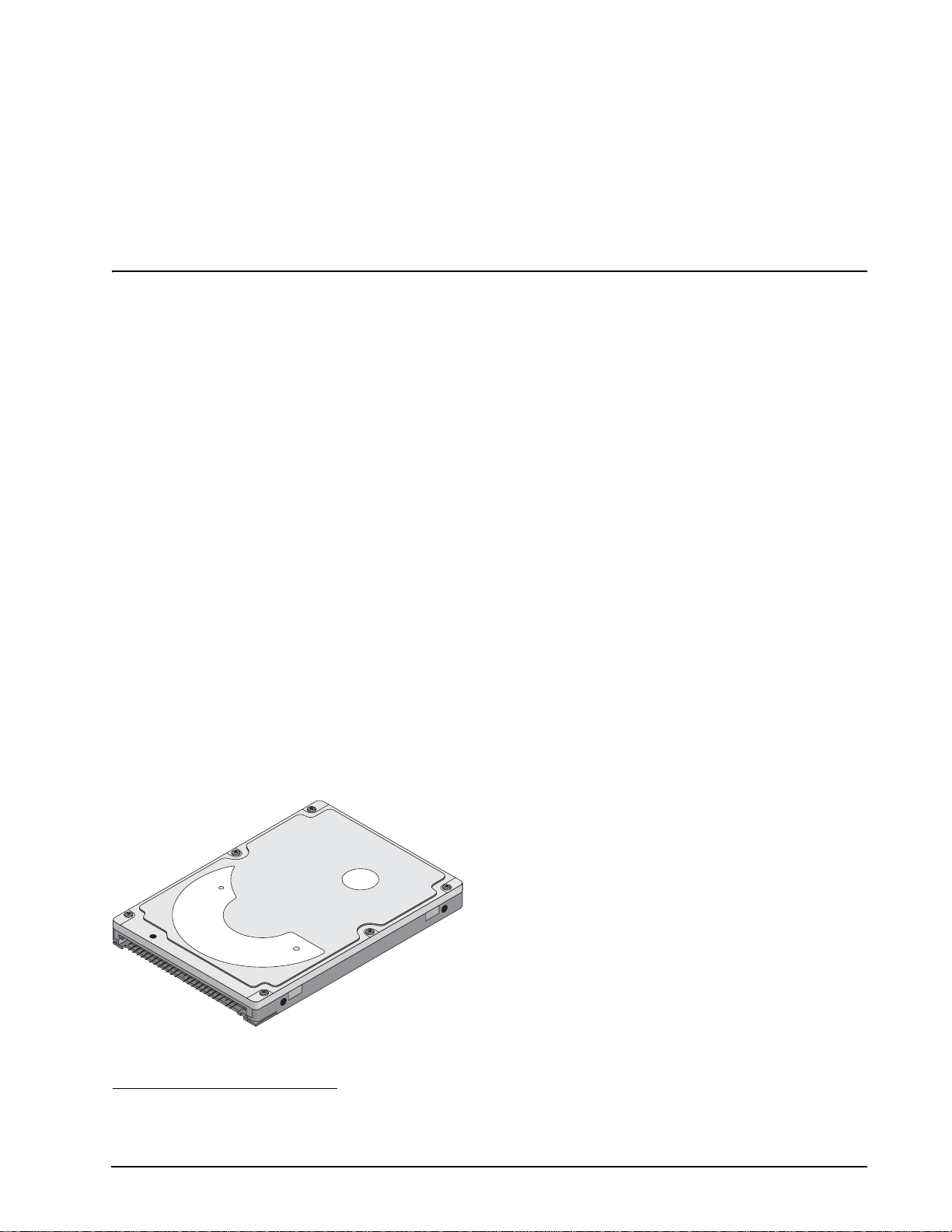
Figure 1. Momentus 42 disc drive . . . . . . . . . . . . . . . . . . . . . . . . . . . . . . . . . . . . . . . . . . . . . . . . . . . . . . 1
Figure 2. Typical 5V startup and operation current profile. . . . . . . . . . . . . . . . . . . . . . . . . . . . . . . . . . . . 9
Figure 3. Jumper settings . . . . . . . . . . . . . . . . . . . . . . . . . . . . . . . . . . . . . . . . . . . . . . . . . . . . . . . . . . . 17
Figure 4. Mounting dimensions—top, side and end view . . . . . . . . . . . . . . . . . . . . . . . . . . . . . . . . . . . 18
Momentus 42 Product Manual, Rev. A vii
Page 10

viii Momentus 42 Product Manual, Rev. A
Page 11
1.0 Introduction
This manual describes the functional, mechanical and interface specifications for the following Seagate
®
Momentus™ 42 drives:
• ST94019A
• ST92014A
• ST93015A
These drives provide the following key features:
1
• 4,200-RPM-class
performance spindle speed and 2-Mbyte buffer combine for superior performance.
• Quiet operation. Fluid Dynamic Bearing (FDB) motor.
• High instantaneous (burst) data transfer rates (up to 100 Mbytes per second) using Ultra DMA mode 5.
• Giant magnetoresistive (GMR) recording heads and EPRML technology, which provide the drives with
increased areal density.
• State-of-the-art cache and on-the-fly error-correction algorithms.
• Full-track multiple-sector transfer capability without local processor intervention.
• 800 Gs nonoperating shock, and 225 Gs operating shock.
• SeaTools diagnostic software performs a drive self-test that eliminates unnecessary drive returns.
• The 3D Defense System™, which includes Drive Defense, Data Defense, and Diagnostic Defense, offers the
industry’s most comprehensive protection for disc drives.
• Support for S.M.A.R.T. drive monitoring and reporting.
• Support for Read Multiple and Write Multiple commands.
• Support for autodetection of master/slave drives that use cable select (CSEL).
Figure 1. Momentus 42 disc drive
1
Actual spin speed is 5,400 RPM.
Momentus 42 Product Manual, Rev. A 1
Page 12

2 Momentus 42 Product Manual, Rev. A
Page 13
2.0 Drive specifications
Unless otherwise noted, all specifications are measured under ambient conditions, at 25°C, and nominal
power. For convenience, the phrases the drive and this drive are used throughout this manual to indicate
ST94019A, ST93015A, and ST92014A model drives.
2.1 Specification summary
The specificatio ns lis ted in th is table ar e for quick reference. For de tails on specification me as ur eme nt o r de finition, see the appropriate section of this manual.
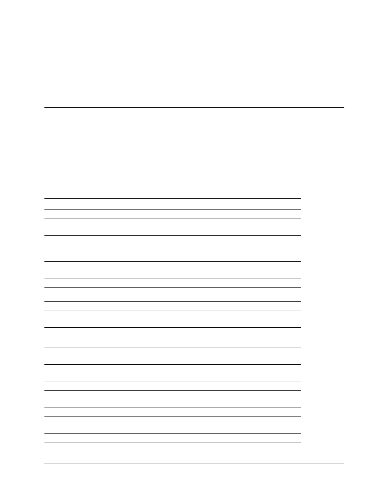
T able 1: Specifications
Drive specification ST94019A ST93015A ST92014A
Formatted Gbytes (512 bytes/sector) 40 30 20
Guaranteed sectors 78,140,160 58,605,120 39,070,080
Bytes per sector 512
Physical read/write heads 2 2 1
Discs 1
Cache (Mbytes) 2
Recording density, BPI (bits/inch max) 642,000 577,000 642,000
Track density . TPI (tracks/inch max) 100,780
Areal density (Bbits/inch
Spindle speed (RPM) 4,200-class performance
Internal data transfer rate OD (Mbytes/sec max) 48.25 46.05 48.25
Sustained data transfer rate OD (Mbytes/sec) 31.0
I/O data-transfer rate (Mbytes/sec max) 100
ATA data-transfer modes supported PIO modes 0–4;
Height 9.5 +/-0.2 mm (0.374 +/-.0078 inches)
Width 69.85 +/-0.25 mm (2.75 +/-0.0098 inches)
Length 100.2 +/-0.25 mm (3.945 +/-0.0098 inches)
Weight (typical) 99 grams (0.218 lb)
Average latency (msec) 5.6
Power-on to ready (sec typical) 3.9
Standby to ready (sec typical) 2.5 sec
Startup current 5V (peak) 1.2 amps
Track-to-track seek time (msec typical) 1.5 (read), 2.0 (write)
Average seek time (msec typical) 12.0
Average seek, read (msec typical) 12.0
2
max) 65 58 65
(spin speed actually 5,400 RPM)
Multiword DMA modes 0–2;
Ultra DMA modes 0–5
Momentus 42 Product Manual, Rev. A 3
Page 14
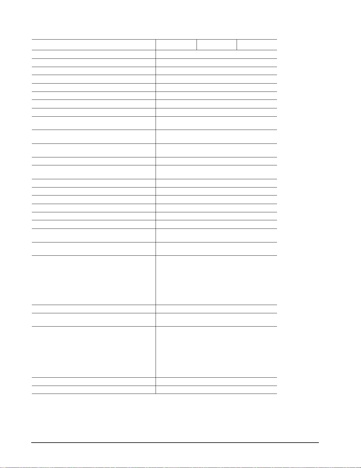
Table 1: Specifi cations (Continued)
Drive specification ST94019A ST93015A ST92014A
Average seek, write (msec typical) 14.0
Full-stroke seek (msec) 22 (typical); 26 (max)
Seek power (typical) 2.4 watts
Read/write power (typical) 2.4 watts
Idle mode (typical) 1.2 watts
Standby mode 0.36 watts (typical)**
Sleep mode 0.36 watts (typical)**
Voltage tolerance (including noise) 5V ± 5%
Ambient temperature 5° to 55°C (operating)
Temperature gradient (°C per hour max) 20°C (operating)
Relative humidity (noncondensing) 5% to 90% (operating)
Relative humidity gradient 30% per hour max
Wet bulb temperature (°C max) 33°C (operating)
Altitude, operating –192.12 m to 3,048 m (–650 ft to 10,000+ ft)
Altitude, nonoperating (below mean sea level, max) –304.8 m to 12,192 m (–1,000 ft to 40,000+ ft)
Shock, operating (Gs max at 2 msec) 225
Shock, nonoperating (Gs max at 2 msec) 800
Shock, nonoperating (Gs max at 1 msec) 800
Shock, nonoperating (Gs max at 0.5 msec) 400
Vibration, operating (max displacement may apply below
10 hz)
Vibration, nonoperating (max displacement may apply
below 22 hz)
Drive acoustics, sound power (bels)
Idle* 2.3 (typical)
Quiet seek 2.5 (typical)
Performance seek 3.0 (typical)
Nonrecoverable read errors 1 per 10
Mean time between failures (power-on hours) 330,000 at 25°C (2400 POH)
Load/Unload (U/UL) cycles
25°C, 50% relative humidity
32°C, 80% relative humidity
5°C, 80% relative humidity
5°C, 10% relative humidity
55°C, 16% relative humidity
Service life 5 Years
Warranty 1 Year
–40° to 65°C (nonoperating)
30°C (nonoperating)
5% to 95% (nonoperating)
40°C (nonoperating)
1.0 Gs (0 to peak, 5–500 Hz)
5.0 Gs (0 to peak, 5–500 Hz)
2.5 (max)
2.7 (max)
3.2 (max)
14
bits read
Max case temperature: 60°C
300,000 software-controlled power on/off cycles
20,000 hard power on/off cycles
100,000 software-controlled power on/off cycles
20,000 hard power on/off cycles
*During periods of drive idle, some o ffline activity may occur according to the S. M.A.R.T. specification, which may increase acoust ic and
power to operational levels.
**Typical notebooks will pull power to the drive when entering S3 and S4; while in the S3 and S4 states, drive sleep and drive standby modes
will not contribute to battery power consumption.
4 Momentus 42 Product Manual, Rev. A
Page 15
2.2 Formatted capacity
Model Formatted capacity Guaranteed sectors Bytes per sector
ST94019A 40 Gbytes 78,140,160 512
ST93015A 30 Gbytes 58,605,120 512
ST92014A 20 Gbytes 39,070,080 512
2.3 Default logical geometry
Cylinders Read/write heads Sectors per track
16,383 16 63
LBA mode
When addressing these d rives in LBA mode, all bl ocks (sectors) are c onsecutively numbered fr om 0 to n–1,
where n is the number of guaranteed sectors as defined above.
2.4 Physical organization
Model Read/write heads Number of discs
ST94019A 2 1
ST93015A 2 1
ST92014A 1 1
Momentus 42 Product Manual, Rev. A 5
Page 16

2.5 Recording and interface technology
Technology Specification
Interface Parallel ATA
Recording method RLL 0,11
Recording density BPI (bits/inch max) 642,000 (ST94019A and ST92014A)
Track density TPI (tracks/inch max) 100,780
2
Areal density (Mbits/inch
Spindle speed (RPM) (± 0.2%) 4,200 clas s performance
Internal data-transfer rate OD (Mbytes/sec max) 48.25 (ST94019A and ST92014A)
Sustained data transfer rate OD (Mbytes/sec max) 31.0
I/O data-transfer rate (Mbytes/sec max) 100 (Ultra DMA mode 5)
Interleave 1:1
Cache buffer
ST94019A, ST93015A and ST92014A
max) 65 (ST94019A and ST92014A)
577,000 (ST93015A)
58 (ST93015A)
(spin speed actually 5,400 RPM)
46.05 (ST93015A)
2 Mbytes (2,048 kbytes)
2.6 Physical characteristics
Height (mm)
(inches)
Width (mm)
(inches)
9.5 +/-0. 2
0.374 +/-0.0078
69.85 +/-0.25
2.75 +/-0.0098
Length (mm)
(inches)
Typical w eig ht (grams)
(pounds)
100.2 +/-0.25
3.945 +/-0.0098
99
0.218
6 Momentus 42 Product Manual, Rev. A
Page 17

2.7 Seek time
Seek measurements are taken with nominal power at 25°C ambient temperature. All times are measured using
drive diagnostics. The specifications below are defined as follows:
• Track-to-track seek time is an average of all possible single-track seeks in both directions.
• Average seek time is a true statistical rand om average of at least 5, 000 measurements of see ks between
random tracks, less overhead.
*Typical seek times (msec) Read Write
Track-to-track 1.5 2.0
Average 12.0 14.0
Full-stroke 22.0 26.0
Average latency 5.6 5.6
*Measured in performance mode
Note. These drives are designed to consistently meet the seek times represented in this manual. Physical seeks,
regardless of mode (such as track-to-track and average), are expected to meet or exceed the noted values.
However, due to the manner in which these drives are formatted, benchmark tests that include command
overhead or measure logical seeks may produce results that vary from these specifications.
2.8 Time to ready
Time to ready Typical Max
Power-on to Ready (sec) 3.9 8.0
Standby to Ready (sec) 2.6 8.0
Momentus 42 Product Manual, Rev. A 7
Page 18

2.9 Power specifications
The drive receives DC power (+5V) through the interface connector.
2.9.1 Power consumption
Power requirements for the drives are listed in the table on page 8. Typical power measurements are based on
an average of drives tested, under nominal conditions, using 5.0V input voltage at 25°C ambient temperature.
• Spinup power
Spinup power is measured from the time of power-on to the time that the drive spindle reaches operating speed.
• Seek mode
During seek mode, the read/write actuator arm moves toward a specific position on the disc surface and does
not execute a read or write operation. Servo electronics are active. Seek mode power is measured based on
three random seek operations every 100 msecs. T his mode is not typical.
• Read/write power and current
Read/write power is meas ured with the heads on track, based on thr ee 63 sector read or writ e operations
every 100 msecs.
• Operating power and current
Operating power is mea sure d using 40 percent random s eek s, 40 p erce nt r ead /write mod e (1 wr i te fo r eac h
10 reads) and 20 percent drive idle mode.
• Idle mode power
Idle mode power is measur ed wi th th e driv e up to s pee d, wi th ser vo ele ctron ics act ive and with the heads in
a random track location.
• Standby mode
During Standby mode, the driv e accepts commands, but the dr ive is not spinning, and the ser vo and read/
write electronics are in power-down mode.
Table 2: DC power
Power dissipation (watts) Average (watts, 25° C) 5V typical amps
Spinup — 1.2
Idle, performance mode 2.00 0.4
Idle, active 1.20 0.24
Idle, low power mode 0.97 0.19
Operating 40% r/w.
40% seek, 20% inop.
Seeking 2.4 0.48
Read 2.4 0.48
Write 2.4 0.48
Standby 0.36 0.07
Sleep 0.36 0.07
2.87
0.72
*During periods of drive idle, some o ffline activity may occur according to the S. M.A.R.T. specification, which may increase acoust ic and
power to operational levels.
8 Momentus 42 Product Manual, Rev. A
Page 19

2.9.1.1 T ypical current profile
A
.5
1.2
1.0
0.8
mps
0.6
0.4
0.2
0.0
+5 Volt Current during spindle start — Typical Amperes
0.0 0.5 1.0 1.5 2.0 2.5 3.0 3.5 4.0
Seconds
4
Figure 2. Typical 5V startup and operation current profile
2.9.2 Conducted noise
Input noise ripple is mea sure d at the ho st sy ste m powe r supp ly acr o ss an equivalent 15-ohm resist ive load on
the +5 volt line.
Using 5-volt power, the drive is expected to operate with a maxim um of 100 mV peak-to-peak square-wav e
injected noise at up to 10 MHz.
Note. Equiva lent resistance is calcul ated by dividing the nomina l voltage by the typical RMS read/write
current.
2.9.3 Voltage tolerance
Voltage tolerance (including noise): 5V ± 5%
Momentus 42 Product Manual, Rev. A 9
Page 20

2.9.4 Power-management modes
The drive provides programmab le power mana gement to provide grea ter energy efficiency. In most systems,
you can control power management through the system setup program. The drive features the following
power-management modes :
Table 3: Power management modes
Power modes Heads Spindle Buffer
Active (operating) Tracking Rotating Enabled
Idle, performance Tracking Rotating Enabled
Idle, active Floating Rotating Disabled
Idle, low power Parked R otating Disabled
Standby Parked Stopped Disabled
Sleep Parked Stopped Disabled
• Active mode
The drive is in Active mode during the read/write and seek operations.
• Idle mode
The buffer remains en abled, and the drive a ccepts a ll comm ands and re turns to Ac tive mode any time disc
access is necessary.
• Standby mode
The drive enters Standby mode when the host sends a Standby Immediate command. If the host has set the
standby timer, the dri ve can also enter Stand by mode automaticall y after the drive has be en inactive for a
specifiable length of time. The standby timer delay is established using a Standby or Idle command. In Standby
mode, the drive buffer is enabled, the heads are parked and the spindle i s at rest. The drive accepts all
commands and returns to Active mode any time disc access is necessary.
• Sleep mode
The drive enters Sleep mode after receiving a Sleep command from the host. In Sleep mode, the drive buffer
is disabled, the he ads are p arke d and the spind le is at rest. T he dr ive leav es Slee p mo de after it rece ives a
Hard Reset or Soft Reset from the host. After receiving a reset, the drive exits Sleep mode and enters Standby
mode with all current translation parameters intact.
• Idle and Standby timers
Each time the drive perfo rms an Active function (read, wr ite or seek), the standby time r is reinitialized and
begins counting down from its specified delay times to zero. If the standby timer reaches zero before any drive
activity is required, the driv e makes a transi tion to Standb y mode. In both Idle and Standby mode, the d rive
accepts all commands and returns to Active mode when disc access is necessary.
10 Momentus 42 Product Manual, Rev. A
Page 21

2.10 Environmental specifications
2.10.1 Ambient temperature
Ambient temperature is defined as the temperature of the environment immediately surrounding the drive.
Actual drive case temperature should not exceed
Above 1,000 feet (305 meters), the maximum temperature is derated linearly by 1°C every 1000 feet.
Operating 5° to 55°C (41° to 131°F)
Nonoperating –40° to 65°C (–40° to 153°F)
2.10.2 Temperature gradient
Operating 20°C per hour (68°F per hour max), without condensation
Nonoperating 30°C per hour (86°F per hour max)
2.10.3 Humidity
2.10.3.1 Relative humidity
Operating 5% to 90% noncondensing (30% per hour max)
65°C (149°F) within the operating ambient conditions.
Nonoperating 5% to 95% noncondensing (30% per hour max)
2.10.3.2 Wet bulb temperature
Operating 33°C (91.4°F max)
Nonoperating 40°C (104°F max)
2.10.4 Altitude
Operating –192.12 m to 3,048 m (–650 ft to 10,000+ ft)
Nonoperating –304.8 to 12,192 m (–1,000 ft to 40,000+ ft)
Momentus 42 Product Manual, Rev. A 11
Page 22

2.10.5 Shock
All shock specificat ions assume that the drive is mou nted securely with the input s hock applied at the drive
mounting screws. Shock may be applied in the X, Y or Z axis.
2.10.5.1 Operating shock
These drives compl y with the performance level s specified in this docu ment when subjected to a ma ximum
operating shock of 225 Gs based on half-sine shock pul ses of 2 msec. Shocks sh ould not be repeated more
than two times per second.
2.10.5.2 Nonoperating shock
The nonoperating s hock l evel that th e driv e can expe rience withou t incur ring ph ysic al d amage or degr adatio n
in performance when subsequently put into operation is 800 Gs based on a nonrepetitive half-sine shock pulse
of 2 msec duration.
The nonoperating s hock l evel that th e driv e can expe rience withou t incur ring ph ysic al d amage or degr adatio n
in performance when subsequently put into operation is 800 Gs based on a nonrepetitive half-sine shock pulse
of 1 msec duration.
The nonoperating s hock l evel that th e driv e can expe rience withou t incur ring ph ysic al d amage or degr adatio n
in performance when subsequently put into operation is 400 Gs based on a nonrepetitive half-sine shock pulse
of 0.5 msec duration.
2.10.6 Vibration
All vibration spec ifications assume that the drive is moun ted securely with the input vibration applied at the
drive mounting screws. Vibration may be applied in the X, Y or Z axis.
2.10.6.1 Operating vibration
The following table lists the maximum vibration lev els that the dri ve may expe rience while meet ing the perfor mance standards specified in this document.
5–500 Hz 1.0 Gs (0 to peak). Max displacement may apply below 10 Hz.
2.10.6.2 Nonoperating vibration
The following table l ists the maximum no noperating vibr ation that the drive may expe rience without incurring
physical damage or degradation in performance when subsequently put into operation.
5–500 Hz 5.0 Gs (0 to peak). Max displacement may apply below 22 Hz.
12 Momentus 42 Product Manual, Rev. A
Page 23

2.11 Acoustics
Drive acoustics a re measured as overall A -weighted acoustic soun d power levels (no pu re tones). All measurements are consistent with ISO document 7779. S ound power measureme nts are taken under essentially
free-field conditions over a reflecting plane. For all tests, the drive is oriented with the cover facing upward.
Note. For seek mode tests, the drive is placed in seek mode only. The number of seeks per second is defined
by the following equation:
(Number of seeks per second = 0.4 / (average latency + average access time)
T able 4: Drive level acoustics
Acoustic mode
Idle* Quiet Seek Performance Seek
2.3 bels (typ)
2.5 bels (max)
*During periods of drive idle, some o ffline activity may occur according to th e S.M.A.R.T. specification, which may increase ac oustic and
power to operational levels.
2.5 bels (typ)
2.7 bels (max)
3.0 bels (typ)
3.2 bels (max)
2.12 Electromagnetic immunity
When properly installed in a representative host system, the drive operates without err ors or degradation in
performance when subjected to the radio frequency (RF) environments defined in the following table:
T a ble 5: Electromagnetic immunity
Performance
Test Description
Electrostatic discharge Contact, HCP, VCP: ± 4 kV; Air: ± 8 kV B EN 61000-4-2: 95
Radiated RF immunity 80 to 1,000 MHz, 3 V/m,
80% AM with 1 kHz sine
900 MHz, 3 V/m, 50% pu lse m odulat ion @ 200
Hz
Electrical fast transient ± 1 kV on AC mains, ± 0.5 kV on external I/O B EN 61000-4-4: 95
Surge immunity ± 1 kV differential, ± 2 kV common, AC mains B EN 61000-4-5: 95
Conducted RF immunity 150 kHz to 80 MHz, 3 Vrms, 80% AM with 1
kHz sine
level
A EN 61000- 4-3: 96
A EN 61000- 4-6: 97
Reference
standard
ENV 50204: 95
Voltage dips, interrupts 0% open, 5 seconds
0% short, 5 seconds
40%, 0.10 seconds
70%, 0.01 seconds
C
C
C
B
EN 61000-4-11: 94
Momentus 42 Product Manual, Rev. A 13
Page 24

2.13 Reliability
Measurement type Specification
Nonrecoverable read errors 1 per 1014 bits read, max.
Mean time between failures 330,0 00 pow e r-on hou rs
Load/Unload (U/UL)
25°C, 50% relative humidity
32°C, 80% relative humidity
5°C, 80% relative humidity
5°C, 10% relative humidity
55°C, 16% relative humidity
Service Life 5 Years
Warranty 1 Year
At nominal power, 25°C ambient temperature.
Max case temperature: 60°C at the case measurement location shown in
Figure 4.
300,000 software-controlled power on/off cycles
20,000 hard power on/off cycles
100,000 software-controlled power on/off cycles
20,000 hard power on/off cycles
2.14 Agency certification
2.14.1 Safety certification
The drives are recogni ze d in ac co rd anc e with UL 1950 and CSA C22.2 (950 ) a nd m eet a ll appl icab le s ec ti ons
of IEC950 and EN 60950 as tested by TUV North America.
2.14.2 Electromagnetic compatibility
Hard drives that display the CE mark comply with the European Union (EU) requirements specified in the Electromagnetic Compatibility Di rective (89/336/EE C). Testing is perform ed to the levels specified by the product
standards for Information Technology Equipment (ITE). Emission levels are defined by EN 55022, Class B and
the immunity levels are defined by EN 55024.
Seagate uses an independent laboratory to confirm compliance with the EC directives specified in the previous
paragraph. Drives are tested in representative end-user systems. Although CE-marked Seagate drives comply
with the directives wh en used in the test systems, we cannot guarantee th at all systems will comply wit h the
directives. The drive is designed for operation inside a properly designed enclosure, with properly shielded I/O
cable (if necessary) and termi nators on all unu sed I/O ports. Compute r manufacture rs and system inte grators
should confirm EMC compliance and provide CE marking for their products.
14 Momentus 42 Product Manual, Rev. A
Page 25

Korean RRL
If these drives have the Korea M inistry of Information a nd Comm unicatio n (MIC) log o, they co mply with paragraph 1 of Article 11 of the Electromagnetic Compatibili ty control Regulation and meet the Electr omagnetic
Compatibility (EMC) Framework req ui remen ts of the Radio Resear c h Labo rator y (RRL) Mini st ry of Informa tion
and Communication Republic of Korea.
These drives have been tested and comply with the Electromagnetic Interference/Electromagnetic Susceptibility (EMI/EMS) for Class B products. Drives are tested in a representative, end-user system by a Korean-recognized lab.
• EUT name (model numbers): ST94019A. ST93015A, and ST92014A
• Certificate numbers:
ST94019A and ST93015A E-H011-03-1191(B)
ST92014A E-H011-03-1192(B)
• Trade name of applicant: Seagate Technology
• Manufacturing date: April 2004
• Manufacturer/nationality: USA, Singapore and China
Australian C-Tick (N176)
If these models h ave the C-Tick marki ng, t hey com ply with the Aus tralia/N ew Z ealand Standard AS/NZS3548
1995 and meet the Electromagnetic Compatibility (EMC) Framework requirements of the Australian Communication Authority (ACA).
2.14.3 FCC verification
These drives are intended to be contained solely within a personal computer or similar enclosure (not attached
as an external device). As such, each drive is considered to be a subassembly even when it is individually marketed to the customer. As a subassembly, no Federal Communications Commission verificati on or ce rt ifi ca tio n
of the device is required.
Seagate Technology LLC has tested this device in enclosures as described above to ensure that the total
assembly (enclosure, dis c drive, motherboard, power supply, etc.) does comply with the limits for a Class B
computing device , pursuant to S ubpart J, Part 15 of the FCC rules. Ope ration with no ncertified a ssemblies is
likely to result in interference to radio and television reception.
Radio and television interferen ce. This equipment generates and uses radio frequency ene rgy and if not
installed and used in strict accordance with th e manufacturer ’s instructions, may cause i nterference to radio
and television reception.
This equipment is designed to provide reasonable protection against such interference in a residential installation. However, there is no guarantee that interference will not occur in a particular installation. If this equipment
does cause interfer ence to radio or te levision, whic h can be determi ned by turning t he equipment on and off,
you are encouraged to try one or more of the following corrective measures:
• Reorient the receiving antenna.
• Move the device to one side or the other of the radio or TV.
• Move the device farther away from the radio or TV.
• Plug the computer into a different outlet so that the receiver and computer are on different branch outlets.
If necessary, you should consult your dealer or an experienced radio /television technician for additional suggestions. You may find helpful the following booklet prepared by the Feder al Communications Commission:
How to Identify and Resolve Radio-Television Interference Problems. This booklet is available from the Superintendent of Documents, U.S. Government Printing Office, Washington, DC 20402. Refer to publ ication number 004-000-00345-4.
Momentus 42 Product Manual, Rev. A 15
Page 26

16 Momentus 42 Product Manual, Rev. A
Page 27

3.0 Configuring and mounting the drive
This section contains the specifications and instructions for configuring and mounting the drive.
3.1 Handling and static discharge precautions
After unpacking, and before installation, the dr ive may be ex posed to pote ntial handli ng and electros tatic discharge (ESD) hazards. Observe the following standard handling and static-discharge precautions:
Caution:
• Keep the drive in the ele ctrosta tic d ischar ge (ES D) bag until you ar e read y for i nstalla tion to limi t the d rive’s
exposure to ESD.
• Before handling the drive, put on a gr oun ded wrist st ra p, or grou nd y ours elf frequently by touching the metal
chassis of a computer that is plugged into a grounded outlet. Wear a grounded wrist strap throughout the entire
installation procedure.
• Handle the drive only by its edges or frame.
• The drive is fragile—handle it with care. Do not press down on the drive top cover.
• Always rest the drive on a padded, antistatic surface until you mount it in the computer.
• Do not touch the connector pins or the printed circuit board.
• Do not remove the factory-installed labels from the drive or cover them with additional labels. Removal voids
the warranty. Some factory-installe d labels contain info rm ati on ne ede d t o ser v ice the drive. Other l ab els ar e
used to seal out dirt and contamination.
3.2 Jumper settings
3.2.1 Master/slave configuration
Use the options jumper block shown in Figure 3 to configure the drive for operation. This jumper block is the 4pin header adjacent to pi ns 1 and 2 of the I/O signal pins. For ad ditional information about us ing the Cable
select option, see Section 3.2.2.
The “Master or single drive” option is the factory default setting.
Drive is master (or single drive)
Drive is slave
Cable select
Figure 3. Jumper settings
Momentus 42 Product Manual, Rev. A 17
Page 28

3.2.2 Cable -s elec t option
Computers that use cable sele ct determine the master and slave drives by selecting or deselecting pin 28,
CSEL, on the interface bus. Master and sl ave dr iv es are det er mined by their physi c al pos i tio n on the cab le. To
enable cable se lect, set a jump er as shown in F igure 3 . R efer t o you r compu ter m anual to de termi ne whet her
your computer supports this option.
3.3 Drive mounting
You can mount the d rive using fo ur screws in the side-moun ting holes or fo ur screws in th e bottom-moun ting
holes. See Figure 4 for drive mounting dimensions. Follow these important mounting precautions when mounting the drive:
• Allow a minimum clearance of 0.030 inches (0.76 mm) around the entire perimeter of the drive for cooling.
• Use only M3 UNC mounting screws.
• Do not overtighten the mounting screws (maximum torque: 4.0 inch-lb).
• Four (4) threads (0.080 inches) minimum screw engagement recommended.
3.945 +/-0.0098
(100.2 +/-.25)
0.490 +/- .010
(12.446 +/- .254)
0.680 +/- .010
(17.27 +/- .254)
Breather Hole
Do not cover
or seal.
.399
(10.135)
.157
(3.9878)
2.750 +/- .0098
(69.85 +/- .25)
inches
(mm)
3.567
(90.602)
3.567
(90.60)
.374 +/- .0078
(9.5 +/- .2)
Both sides
2X .118
.551
(13.99)
.551
(13.99)
Figure 4. Mounting dimensions—top, side and end view
Recommended case
temp. measurement location
2X M3 X 0.5-6H
Mounting holes
Both sides
.12 min. full thread
4X M3 X 0.5-6H
Mounting holes
.10 min. full thread
2.430
(61.722)
.160
(4.06)
18 Momentus 42 Product Manual, Rev. A
Page 29

4.0 ATA interface
These drives use t he industry-standard ATA task file inter face that supports 16-bit d ata transfers. It suppo rts
ATA programmed input/output (PIO) mode s 0–4; m ultiwor d DMA m odes 0– 2, and Ul tra DMA mod es 0–5. The
drive also supports the use of the IORDY signal to provide reliable high-speed data transfers.
For detailed information about the ATA interface, refer to the draft of AT Attachment with Packet Interface
Extension (ATA/ATAPI-6), NCITS T13 1410D, subsequently referred to as the Draft ATA-6 Standard.
4.1 ATA interface signals and connector pins
The following table summarizes the signals on the 44-pin ATA interface connector. For a detailed description of
these signals, refer to the Draft ATA-6 Standard.
Table 6: Connector signals
Connector
Signal Name
RESET- 1 1 2 2 Ground
DD7 3 3 4 4 DD8
DD6 5 5 6 6 DD9
DD5 7 7 8 8 DD10
DD4 9 9 10 10 DD11
DD3 11 11 12 12 DD12
DD2 13 13 14 14 DD13
DD1 15 15 16 16 DD14
DD0 17 17 18 18 DD15
Ground 19 19 20 20 (keypin)
DMARQ 21 21 22 22 Ground
DIOW- 23 23 24 24 Ground
DIOR- 25 25 26 26 Ground
IORDY 27 27 28 28 PSYNC:CSEL
DMACK- 29 29 30 30 Ground
INTRQ 31 31 32 32 IOCS16DA1 33 33 34 34 PDIAGDA0 35 35 36 36 DA2
CS1FX- 37 37 38 38 CS3FXDASP- 39 39 40 40 Ground
+5 V (Logic) 41 41 42 42 +5V (Motor)
Ground (Return) 43 43 44 44 No connection
Contact
Cable
Conductor
Cable
Conductor
Connector
Contact Signal Name
Momentus 42 Product Manual, Rev. A 19
Page 30

4.1.1 Supported ATA commands
The following table lists ATA-standard commands that the dr ive s upp or ts. For a detailed des cr i ption of the ATA
commands, refer to th e Draft ATA-6 Standard. See “S.M.A.R.T. commands” on page 26. for details and sub-
commands used in the S.M.A.R.T. implementation.
Table 7: Supported commands
Command name Command code (in hex)
ATA-standard commands
ATA Device Configuration Overlay B1
ATA Service A2
Check Power Mode 98
Download Microcode 92
Execute Device Diagnostics 90
Flush Cache E7
Flush Cache Extended EA
Format Track (Lega cy ) 50
Identify Device EC
Idle 97
Idle Immediate 95
Initialize Device Parameters 91
Read Buffer E4
Read DMA C8
Read DMA Extended 25
Read Log Extended 22
Read Multiple C4
Read Multiple Extended 29
Read Native Max Address F8
Read Native Max Address Extended 27
Read Sectors 20
Read Sectors Extended 24
Read Verify Sectors 40
Read Verify Sectors Extended 42
Recalibrate 10
Security Disable Password F6
Security Erase Prepare F3
Security Erase Unit F4
Security Freeze Lock F5
Security Set Password F1
H
H
H, E5H
H
H
H
H
H
H
H, E3H
H, E1H
H
H
H, C9H
H
H
H
H
H
H
H, 21H
H
H, 41H
H
H
H
H
H
H
H
20 Momentus 42 Product Manual, Rev. A
Page 31

Table 7: Supported commands (Continued)
Command name Command code (in hex)
Security Unlock F2
Seek 70
Set Drive Parameters 91
Set Features EF
Set Max Address F9
Note: Individual Set Max commands are identified by the value
placed in the Set Max Features
register as defined to the right.
H
H
H
H
H
Address:
Password:
Lock:
Unlock:
Freeze Lock:
Set Multiple Mode C6
Sleep 99
S.M.A.R.T. B0
Standby 96
Sta ndb y Imm ed iate 94
Vendor Unique 9A
Write Buffer E8
Write DMA CA
Write DMA Extended 35
Write Log Extended 32
Write Multiple C5
Write Multiple Extended 39
Write Sectors 30
Write Sectors Extended 34
H
H, E6H
H
H, E2H
H, E0H
H, FAH, FBH
H
H, CBH
H
H
H
H
H, 31H
H
ATA-standard power-management commands
00
01
02
03
04
H
H
H
H
H
Check Power Mode 98H or E5
Idle 97H or E3
Idle Immediate 95H or E1
Sleep 99H or E6
Standby 96H or E2
Sta ndb y Imm ed iate 94H or E0
H
H
H
H
H
H
ATA-standard security commands
Security Set Password F1
Security Unlock F2
Security Erase Prepare F3
Security Erase Unit F4
H
H
H
H
Momentus 42 Product Manual, Rev. A 21
Page 32

Table 7: Supported commands (Continued)
Command name Command code (in hex)
Security Freeze Lock F5
Security Disable Password F6
H
H
4.1.2 Identify Device command
The Identify Device command (command code ECH) transfers information about the drive to the host following
power up. The data is o rg ani ze d a s a sin gle 512-byte block of data, who se c onte nts are sho w n in the table o n
page 27. All reserved bits or words s hould be set to zero. Parameter s listed with an “x” are drive-sp ecific or
vary with the state of the drive. See Section 2.0 on page 3 for default parameter settings.
The following commands contain drive-specific features that may not be included in the Draft AT A-6 Standard.
Word Description Value
0
1 Number of logical cylinders 16,383
2 ATA-reserved 0000
3 Number of logical heads 16
4 Retired 0000
5 Retired 0000
6 Number of logical sectors per logical track: 63 003F
7–9 Retired 0000
10–19 Serial number: (20 ASCII characters, 0000H = none) ASCII
Configuration informa tio n:
• Bit 15: 0 = ATA; 1 = ATAPI
• Bit 7: removable media
• Bit 6: removable controller
• Bit 0: reserved
0C5A
H
H
H
H
H
H
20 Retired 0000
21 Retired 0400
22 Obsolete 0000
23–26 Firmware revision
x.xx
(8 ASCII character string, padded with blanks to end of string)
27–46 Drive model number: (40 ASCII characters, padded with blanks to end of
string)
ST94019A
ST93015A
ST92014A
47 (Bits 7–0) Maximum sectors per interrupt on Read multiple and Write mul-
8010
tiple (16)
48 Reserved 0000
49 Standard Standby timer, IORDY supported and may be disabled 2F00
50 ATA-reserved 0000
51 PIO data-transfer cycle timing mode 0200
52 Retired 0200
53 Words 54–58, 64–70 and 88 are valid 0007
H
H
H
H
H
H
H
H
H
H
22 Momentus 42 Product Manual, Rev. A
Page 33

Word Description Value
54 Number of current logical cylinders xxxx
55 Number of current logical heads xxxx
56 Number of current logical sectors per logical track xxxx
57–58 Current capacity in sectors xxxx
59 Number of sectors transferred during a Read Multiple or Write Multiple
xxxx
command
60–61 Total number of user-addressable LBA sectors available
(see Section 2.2 for related information)
ST94019A = 78,140,160
ST93015A = 58,605,120
ST92014A = 39,070,080
62 Retired 0000
63 Multiword D MA activ e and m odes suppo rted (se e note fo llow ing thi s t able) xx07
64 Advanced PIO modes supported (modes 3 and 4 supported) 0003
65 Minimum multiword DMA transfer cycle time per word (120 nsec) 0078
66 Recommended multiword DMA transfer cycle time per word (120 nsec) 0078
67 Minimum PIO cycle time without IORDY flow control (240 nsec) 00F0
68 Minimum PIO cycle time with IORDY flow control (120 nsec) 0078
69–74 ATA-reserved 0000
75 Queue depth 0000
76–79 ATA-reserved 0000
80 Major version number 007E
81 Minor version number 0000
82 Command sets supported 346B
83 Command sets supported 7D01
84 Command sets support extension 4003
85 Command sets enabled 34xx
86 Command sets enabled 3xxx
87 Command sets enable extension 4003
88 Ultra DMA support and current mode
xx3F
(see note following this table)
H
H
H
H
H
H
H
H
H
H
H
H
H
H
H
H
H
H
H
H
H
H
H
H
89 Security erase time 0000
90 Enhanced se cur ity erase tim e 0000
91 Advanced power management value 0040
92 Master password revision code FFFE
93 Hardware reset value (see description following this table) xxxx
94 Auto acoustic management setting xxxx
95–127 ATA-reserved 0000
128 Security stat us 0001
H
H
H
H
H
H
H
H
Momentus 42 Product Manual, Rev. A 23
Page 34

Word Description Value
129–
Seagate-reserved xxxx
159
160–
ATA-reserved 0000
254
255 Integrity word xxA5
Note. See the bit descriptions below for words 63, 88, 93 and 94 of the Identify Drive data.
Description (if bit is set to 1)
Bit Word 63
0 Mult iword DMA mode 0 is supported.
1 Mult iword DMA mode 1 is supported.
2 Mult iword DMA mode 2 is supported.
8 Multiword DMA mode 0 is currently active.
9 Multiword DMA mode 1 is currently active.
10 Multiword DMA mode 2 is currently active.
Bit Word 88
0 Ultra DMA mode 0 is supported.
H
H
H
1 Ultra DMA mode 1 is supported.
2 Ultra DMA mode 2 is supported.
3 Ultra DMA mode 3 is supported.
4 Ultra DMA mode 4 is supported.
8 Ultra DMA mode 0 is currently active.
9 Ultra DMA mode 1 is currently active.
10 Ultra DMA mode 2 is currently active.
11 Ultra DMA mode 3 is currently active.
12 Ultra DMA mode 4 is currently active.
13 Ultra DMA mode 5 is currently active.
Bit Word 93
13 1 = 80-conductor cable detected, CBLID above V
0 = 40-conductor cable detected, CBLID below VIL
IH
24 Momentus 42 Product Manual, Rev. A
Page 35

4.1.3 Set Featu res command
This command controls the implementation of various features that the drive supports. When the drive receives
this command, it sets BSY, checks the contents of the Features re gister, clears BSY and generates an interrupt. If the value in the register does not represent a feature that the driv e supports, the comman d is aborted .
Power-on default has the rea d look-ahe ad and write cach ing features enabled . The ac ceptable va lues for th e
Features register are defined as follows:
T able 8: Features register values
02
03
05
55
82
AA
F1
Enable write cache (default).
H
Set transfer mode (based on value in Sector Count register).
H
Sector Count register values
00
H
01
H
08
H
09
H
0A
H
0B
H
0C
H
20
H
21
H
22
H
40
H
41
H
42
H
43
H
44
H
45
H
Enable advanced power management
H
Disable read look-ahead (read cache) feature.
H
Disable write cache.
H
Enable read look-ahead (read cache) feature (default).
H
Report full capacity available
H
Set PIO mode to default (PIO mode 2).
Set PIO mode to default and disable IORDY (PIO mode 2).
PIO mode 0
PIO mode 1
PIO mode 2
PIO mode 3
PIO mode 4 (default)
Multiword DMA mode 0
Multiword DMA mode 1
Multiword DMA mode 2
Ultra DMA mode 0
Ultra DMA mode 1
Ultra DMA mode 2
Ultra DMA mode 3
Ultra DMA mode 4
Ultra DMA mode 5
Note. At power-on, or after a hardware or software reset, the de fault values of the features ar e as indi-
cated above.
Momentus 42 Product Manual, Rev. A 25
Page 36

4.1.4 S.M.A.R.T. commands
S.M.A.R.T. provides near-ter m failure prediction for disc driv es. When S.M.A.R.T. is enabled, the dr ive monitors predetermined driv e attr i bute s tha t are susceptible t o d egrad ati on ov er time. If self-monito ri ng de termi nes
that a failure is likely, S.M.A.R.T. makes a sta tus report available to t he host. Not all failure s are predictable.
S.M.A.R.T. predictability i s limited to the attribute s the drive can moni tor. For more information on S.M.A.R.T.
commands and implementation, see the Draft ATA-6 Standard.
SeaTools diagnostic software a ctiva tes a b uilt-in driv e self -test ( DST S. M.A.R .T. command for D4
) that elimi-
H
nates unnecessary drive returns. The diagnostic software ships with all new drives and is also available at:
http://seatools.sea
gate.com.
This drive is shipped with S.M.A.R.T. features disabled. Y ou must have a recent BIOS or software package that
supports S.M.A.R.T. to enable this feature. The table below shows the S.M.A.R.T. command c odes that the
drive uses.
Table 9: Supported S.M.A.R.T. commands
Code in features register S.M.A.R.T. command
D0
D1
D2
D3
D4
D5
D6
D7
D8
D9
DA
H
H
H
H
H
H
H
H
H
H
H
S.M.A.R.T. Read Data
Vendor-specific
S.M.A.R.T. Enable/Disable Attribute Autosave
S.M.A.R.T. Save Attribute Values
S.M.A.R.T. Execute Off-line Immediate (runs DST)
S.M.A.R.T. Read Log Sector
S.M.A.R.T. Write Log Sector
Vendor-specific
S.M.A.R.T. Enable Operations
S.M.A.R.T. Disable Operations
S.M.A.R.T. Return Status
Note. If an appropriate code is not written to the Features Register, the command is aborted and 0x 04
(abort) is written to the Error register.
26 Momentus 42 Product Manual, Rev. A
Page 37

5.0 Seagate Technology support services
Online Services
Internet
www.seagate.com for informatio n about Seagate products and servic es. Worldwide support is availab le 24
hours daily by e-mail for your questions.
Presales Support: www.sea
Technical Support: www.sea
gate.com/support/email/email_presales.html or DiscPresales@Seagate.com
gate.com/support/email/email_disc_support.html or DiscSupport@Seagate.com
mySeagate
my.seagate.com is the industry’s first Web por tal designed specific ally for OEMs and di stributors. It provi des
self-service a ccess to cr itical app lications, personaliz ed content and the tool s that allo w our partner s to manage their Seagate account fun ctions. Submit prici ng requests, order s and returns through a singl e, passwordprotected Web interface—anytime, anywhere in the world.
reseller.seagate.com
reseller.seagate.com supports Seag ate resellers with produc t information, program benefi ts and sales tools.
You may register fo r customized communication s that are not available on the web . These communications
contain product launc h, EOL, pr icing, promoti ons and oth er channel- related infor mation. To learn more about
the benefits or to register, go to reseller.sea
gate.com, any time, from anywhere in the world.
Automated Phone Services
SeaFONE® (1-800-SEAGATE) is the Seagate toll-free number (1-800-732-4283) to access our automated
self-help and di rectory a ssistance f or Seagate s upport ser vices. Using a touch- tone phone, you can find service and support phone numbers for disc drives 24 hours daily. International callers can reac h this service by
dialing +1-405-324-477 0.
Presales, Technical Support and Warranty Service
Presales Support
Our Presales Suppo rt staff can help you deter mine which Seagate products are best suited for your specific
application or computer system.
Technical Support
If you need help installing your dr ive, consult your system's doc ume ntation or contact the dealer 's s upp ort ser vices department for assista nce specific to your sy stem. Seagate techn ical support is also av ailable to assist
you online at support.sea
tion and your drive’s “ST” model number available.
SeaTDD™ (+1-405-324-3655) is a telecommuni catio ns de vice for the d eaf ( TDD). You can send questions or
comments 24 hours d aily and e xcha nge m essag es wi th a technic al s upport speci alist during nor mal b usine ss
hours for the call center in your region.
Momentus 42 Product Manual, Rev. A 27
gate.com or through one of our call centers. Have your system configuration informa-
Page 38

Warranty Service
Seagate offers worldwide customer supp ort for Seagate drives. Seagate dis tributors, OEMs and other direct
customers should contact their Seagate service center representative for warranty-related issues. Resellers or
end users of drive products should contact their place of purchase or one of the Seagate warranty service centers for assistance. Have your drive’s “ST” model number and serial number available.
Authorized Service Centers
In some locations outside the US, you can contact an Authorized Service Center for service.
28 Momentus 42 Product Manual, Rev. A
Page 39

USA/Canada/Latin America Support Services
Presales Support
Call Center Toll-free Direct dial FAX
Americas 1-877-271-3285
Technical Support
Call Center Toll-free Direct dial FAX
Americas 1-800-SEAGATE
Warranty Service
Call Center Toll-free Direct dial FAX / Internet
USA, Mexico and 1-800-468-3472
Latin America
Canada
Memofix
Brazil
MA Centro de Serviços
1
Hours of operation are 8:00 A.M. to 11:45 A.M. and 1:00 P.M. to 6:00 P.M., Monday through Friday (Central time)
2
For product-specific phone number
3
Hours of operation are 8:00 A.M. to 8:00 P.M., Monday through Friday (Central time)
4
Hours of operation are 8:30 A.M. to 12:15 P.M. and 1:30 P.M. to 5:30 P.M., Monday through Friday (Central time)
5
Authorized Service Center
5
1-800-636-6349 +1-905-660-4936 +1-905-660-4951
5
— +55-21-2509-7267 +55-21-2507-6672
1
+1-405-324-4730
2
+1-405-324-4700
4
+1-405-324-4720
1
3
4
+1-405-324-4704
+1-405-324-4702
+1-405-324-4722
www.memofix.com
www.mainformatica.com.br/produtos.htm
Momentus 42 Product Manual, Rev. A 29
Page 40

European Support Services
For presales and technical support in Europe, dial the toll-free number for your specific location. If your location
is not listed h ere, dial our presales and te chnical support call center at +1-405-324-4714 from 8:00
11:45
A.M. and 1:00 P.M. to 5:00 P.M. (Central Europe time) Monday through Friday. The presales and technical
support call center is located in Oklahoma City, USA.
For European warranty service, dial the toll-free number for your specific location. If your location is not listed
here, dial our European warranty service center at +31-20-316-7222 from 8:30
A.M. to 5:00 P.M. (Central
Europe time) Monday through Friday. The warranty service center is located in Amsterdam, The Netherlands.
Toll-Free Support Numbers
Call Center Presales and Technical Support Warranty Service
Austria 0 800-20 12 90 0 800-20 12 90
Belgium 00 800-47324283 (00 800-4SEAGATE) 00 800-47324289
Denmark 00 800-47324283 00 800-47324289
France 00 800-47324283 00 800-47324289
Germany 00 800-47324283 00 800-47324289
Ireland 00 800-47324283 00 800-47324289
Italy 00 800-47324283 00 800-47324289
Netherlands 00 800-47324283 00 800-47324289
Norway 00 800-47324283 00 800-47324289
Poland 00 800-311 12 38 00 800-311 12 38
Spain 00 800-47324283 00 800-47324289
Sweden 00 800-47324283 00 800-47324289
Switzerland 00 800-47324283 00 800-47324289
Turkey 00 800-31 92 91 40 00 800-31 92 91 40
United Kingdom 00 800-47324283 00 800-47324289
A.M. to
FAX Servi ces—Al l Europe (toll call)
Technical Support +1-405-324-4702
Warranty Service +31-20-653-3513
Africa/Middle East Support Services
For presales and techn ical suppo rt in Africa and the Midd le East, dia l our presales and technic al support c all
center at +1-405-32 4-471 4 from 8:00
day through Friday. The presales and technical support call center is located in Oklahoma City, USA.
For warranty service in Afric a and th e Middle East, dia l our Eur opean war ranty se rvice c enter at + 31-20-3167222 from 8:30
A.M. to 5:00 P.M. (Centr al Europ e time ) Mond ay throu gh Fr iday, or send a FAX to +31-20-653-
3513. The warranty service center is located in Amsterdam, The Netherlands.
A.M. to 11:45 A.M. and 1:00 P.M. to 5:00 P.M. (Central Europe time) Mon-
30 Momentus 42 Product Manual, Rev. A
Page 41

Asia/Pacific Support Services
For Asia/Pacific pr esales and technical s upport, dial the toll-fre e number for your specific location. The Asia/
Pacific toll-free numbers are available from 6:00
ern time) Monday through Friday, except as noted. If your location is not listed here, direct dial one of our technical support locati ons. Warranty service is available from 9:00
10:00
P.M. to 7:00 P.M. November through March (Australian Eastern time) Monday through Friday.
Call Center Toll-free Direct dial FAX
Australia 1800-14-7201 — —
China (Mandarin)
1, 4
800-810-9668 +86-10-6225-5336 —
Hong Kong 800-90-0474 — —
Hong Kong (Cantonese)
2, 4
India
1, 4
001-800-0830-1730 — —
1-600-33-1104 — —
Indonesia 001-803-1-003-2165 — —
3, 4
Japan
0034 800 400 554 — —
Malaysia 1-800-80-2335 — —
New Zealand 0800-443988 — —
Singapore 800-1101-150 — +65-6488-7525
Taiwan (Mandarin)
1, 4
00-800-0830-1730 — —
Thailand 001-800-11-0032165 — —
Warranty Service
Call Center Toll-free Direct dial FAX
Asia/Pacific — +65-6485-3595 +65-6485-4860
Australia 1800-12-9277 — —
4
India
— +91-44-821-6164 +91-44-827-2461
A.M. to 10:45 A.M. and 12:00 P.M. to 6:00 P.M. (Australian East-
A.M. to 6:00 P.M. April through Octob er, and
1
Hours of operation are 8:30 A.M. to 5:30 P.M., Monday through Friday (Australian Western time).
2
Hours of operation are 9:00 A.M. to 6:00 P.M., Monday through Saturday.
3
Hours of operation are 9:30 A.M. to 6:30 P.M., Monday through Friday (Japan time).
4
Authorized Service Center
Momentus 42 Product Manual, Rev. A 31
Page 42

32 Momentus 42 Product Manual, Rev. A
Page 43

Index
Numerics
3D Defens e System 1
A
acoustics 13
Active mode 10
adio frequency (RF) 13
agency certification (regulatory) 14
altitude 11
ambient co nditions 3
ambient temperature 7, 11
areal density 1, 6
ATA interface 19
ATA-standard commands 20
Australian C-Tick 15
autodetection 1
average seek time 7
B
BPI 6
buffer 1
burst 1
C
cable select 1
cable-select option 18
cache 1
case temperature 11
CE mark 14
certification 14
Check Power Mode 21
commands 20
compliance 14
conducted noise 9
conducted RF immunity 13
configuring the drive 17
connector pins 19
CSA C22.2 (950) 14
CSEL 18
C-Tick 15
current profile 9
cycles 14
D
Data Defense 1
data-transfer rates 1
DC power 8
density 6
Diagnostic Defense 1
diagnostic software 1, 26
discs 5
dissipation 8
Download Microcode 20
Drive Defense 1
drive diagnostics 7
drive monitoring 1
drive self-test 1, 26
DST 26
E
electrical fast transient 13
electromagnetic compatibility 14
Electromagnetic Compatibility Directive 14
electromagnetic immunity 13
electrostatic discharge 13
EMC compliance 14
EN 60950 14
enclosures 15
environmental specifications 11
EPRML 1
error-correction algorithms 1
errors 14
European Union 14
Execute Device Diagnostics 20
F
failure prediction 26
FCC verification 15
Features register 25
Flush Cache 20
Flush Cache Extended 20
formatted capacity 5
frequency 13
G
GMR 1
guaranteed sectors 5
H
handling 17
heads 1, 5
height 6
humidity 11
I
I/O data-transfer rate 6
Identify Device 20
Identify Device command 22
Idle 8, 21
Idle and Standby timers 10
Idle Immediate 21
Idle mode 10
Idle mode power 8
Momentus 42 Product Manual, Rev. A 33
Page 44

IEC950 14
Information Technology Equi pm ent 14
Initialize Device Parameters 20
interface 6, 19
interface signals 19
interference 15
interleave 6
internal data-transfer rate OD 6
ISO document 7779 13
J
jumper settings 17
K
Korean RRL 15
L
LBA mode 5
length 6
Load/Unload 14
logical geometry 5
M
master/slave 1
Master/slave configuration 17
maximum temperature 11
Mean time between failures (MTBF) 14
modes 19
monitoring 1
mounting the drive 17, 18
N
noise 9
nominal power 3
nonoperating shock 12
nonoperating vibration 12
nonrecoverable read errors 14
O
operating 8
operating power and current 8
operating shock 12
operating vibration 12
P
physical characteristics 6
physical organization 5
pins 19
PIO 19
power consumption 8
power dissipation 8
power management 10
power on/off cycles 14
power specifications 8
power-management comma nds 21
power-management modes 10
Power-on to Ready 7
precautions 18
programmable power management 10
R
radiated RF immunity 13
radio and television interference 15
random track location 8
Read Buffer 20
Read DMA 20
Read DMA Extended 20
read errors 14
Read Multiple 1, 20
Read Multiple Extended 20
Read Native Max Address 20
Read Native Max Address Extended 20
Read Sectors 20
Read Sectors Extended 20
Read Verify Sectors 20
Read Verify Sectors Extended 20
read/write heads 5
read/write power and current 8
recording and interface technology 6
recording density 6
recording heads 1
recording method 6
register 25
relative humidity 11
reliability 14
resistance 9
RF 13
S
S.M.A.R.T. 21
S.M.A.R.T. commands 26
S.M.A.R.T . drive monitoring 1
safety certification 14
screws 18
SeaTools 1, 26
sectors 5
security commands 21
Security Disable Password 22
Security Erase Prepare 21
Security Erase Unit 21
Security Freeze Lock 22
Security Set Password 21
Security Unlock 21
Seek 21
seek mode 8
seek time 7
34 Momentus 42 Product Manual, Rev. A
Page 45

Seeking 8
Service Life 14
servo electronics 8
Set Features 21
Set Features command 25
Set Max 21
Set Multiple Mode 21
shock 12
signals 19
single-track seeks 7
Sleep 8, 21
Sleep mode 10
sound 13
specifications 3
spindle speed 6
Spinup 8
spinup power 8
Standby 8, 21
Standby Immediate 21
Standby mode 8, 10
Standby to Ready 7
static-discharge precautions 17
subassembly 15
support services 27
surge immunity 13
Write Multiple 1, 21
Write Multiple Extended 21
Write Sectors 21
Write Sectors Extended 21
T
technical support serv ic es 27
temperature 11
temperature gradient 11
time to ready 7
timers 10
track density 6
track-to-track seek time 7
TUV North America 14
U
UL 1950 14
V
vibration 12
voltage 9
voltage dips, interrupts 13
voltage tolerance 9
W
Warranty 14
weight 6
wet bulb temperature 11
width 6
Write Buffer 21
Write DMA 21
Write DMA Extended 21
Momentus 42 Product Manual, Rev. A 35
Page 46

36 Momentus 42 Product Manual, Rev. A
Page 47

Page 48

Seagate Technology LLC
920 Disc Drive, Scotts Valley, California 95066-4544, USA
Publication Number: 100316029, Rev. A, Printed in USA
 Loading...