

Page 1
Product Manual
Momentus® 5400.1
ST94011A
ST94811A
ST92011A
ST92811A
100271716
Rev . F
August 2007
Page 2

©2004-2007, Seagate Technology LLC All rights reserved.
Publication number: 100271716, Rev. F
August 2007
Seagate, Seagate Technology and the Wave logo are registered trademarks of Seagate
Technology LLC in the United States and/or other countries. Momentus, SeagateSeaBOARD, SeaFONE, SeaTDD, and SeaTools are either trademarks or registered trademarks of Seagate Te chnolog y LLC or one of it s af filiate d comp a nies in the United States a nd/
or other countries. All other trademarks or registered trademarks are the property of their
respective owners.
One gigabyte, or GB, equals one billion bytes and one terabyte, or TB, equals one trillion
bytes when referring to hard drive capacity. Accessible capacity may vary depending on
operating environment and formatting. Quantitative usage examples for various applications
are for illustrative p urpo ses. Actual quan tities w ill vary based on vari ou s factors, including fi le
size, file format, features and application software. Seagate reserves the right to change,
without notice, product offerings or specifications.
Page 3

Momentus 5400.1 Product Manual, Rev. F
i
Contents
1.0 Introduction. . . . . . . . . . . . . . . . . . . . . . . . . . . . . . . . . . . . . . . . . . . . . . . . . . . . . . . . . . . . . . . . . . . 1
2.0 Drive specifications . . . . . . . . . . . . . . . . . . . . . . . . . . . . . . . . . . . . . . . . . . . . . . . . . . . . . . . . . . . . 3
2.1 Specification summary . . . . . . . . . . . . . . . . . . . . . . . . . . . . . . . . . . . . . . . . . . . . . . . . . . . . 3
2.2 Formatted capacity . . . . . . . . . . . . . . . . . . . . . . . . . . . . . . . . . . . . . . . . . . . . . . . . . . . . . . . 5
2.3 Default logical geometry . . . . . . . . . . . . . . . . . . . . . . . . . . . . . . . . . . . . . . . . . . . . . . . . . . . 5
2.4 Physical organization . . . . . . . . . . . . . . . . . . . . . . . . . . . . . . . . . . . . . . . . . . . . . . . . . . . . . 5
2.5 Recording and interface technology . . . . . . . . . . . . . . . . . . . . . . . . . . . . . . . . . . . . . . . . . . 6
2.6 Physical characteristics . . . . . . . . . . . . . . . . . . . . . . . . . . . . . . . . . . . . . . . . . . . . . . . . . . . 6
2.7 Seek time. . . . . . . . . . . . . . . . . . . . . . . . . . . . . . . . . . . . . . . . . . . . . . . . . . . . . . . . . . . . . . . 7
2.8 Time to ready. . . . . . . . . . . . . . . . . . . . . . . . . . . . . . . . . . . . . . . . . . . . . . . . . . . . . . . . . . . . 7
2.9 Power specifications . . . . . . . . . . . . . . . . . . . . . . . . . . . . . . . . . . . . . . . . . . . . . . . . . . . . . . 8
2.9.1 Power consumption . . . . . . . . . . . . . . . . . . . . . . . . . . . . . . . . . . . . . . . . . . . . . . . 8
2.9.2 Conducted noise . . . . . . . . . . . . . . . . . . . . . . . . . . . . . . . . . . . . . . . . . . . . . . . . . 9
2.9.3 Voltage tolerance. . . . . . . . . . . . . . . . . . . . . . . . . . . . . . . . . . . . . . . . . . . . . . . . . 9
2.9.4 Power-management modes. . . . . . . . . . . . . . . . . . . . . . . . . . . . . . . . . . . . . . . . 10
2.10 Environmental specifications. . . . . . . . . . . . . . . . . . . . . . . . . . . . . . . . . . . . . . . . . . . . . . . 11
2.10.1 Ambient temperature . . . . . . . . . . . . . . . . . . . . . . . . . . . . . . . . . . . . . . . . . . . . . 11
2.10.2 Temperature gradient. . . . . . . . . . . . . . . . . . . . . . . . . . . . . . . . . . . . . . . . . . . . . 11
2.10.3 Humidity. . . . . . . . . . . . . . . . . . . . . . . . . . . . . . . . . . . . . . . . . . . . . . . . . . . . . . . 11
2.10.4 Altitude. . . . . . . . . . . . . . . . . . . . . . . . . . . . . . . . . . . . . . . . . . . . . . . . . . . . . . . . 11
2.10.5 Shock. . . . . . . . . . . . . . . . . . . . . . . . . . . . . . . . . . . . . . . . . . . . . . . . . . . . . . . . . 12
2.10.6 Vibration. . . . . . . . . . . . . . . . . . . . . . . . . . . . . . . . . . . . . . . . . . . . . . . . . . . . . . . 12
2.11 Acoustics. . . . . . . . . . . . . . . . . . . . . . . . . . . . . . . . . . . . . . . . . . . . . . . . . . . . . . . . . . . . . . 13
2.12 Electromagnetic immunity . . . . . . . . . . . . . . . . . . . . . . . . . . . . . . . . . . . . . . . . . . . . . . . . . 13
2.13 Reliability . . . . . . . . . . . . . . . . . . . . . . . . . . . . . . . . . . . . . . . . . . . . . . . . . . . . . . . . . . . . . 14
2.14 Agency certification . . . . . . . . . . . . . . . . . . . . . . . . . . . . . . . . . . . . . . . . . . . . . . . . . . . . . . 14
2.14.1 Safety certification . . . . . . . . . . . . . . . . . . . . . . . . . . . . . . . . . . . . . . . . . . . . . . . 14
2.14.2 Electromagnetic compatibility. . . . . . . . . . . . . . . . . . . . . . . . . . . . . . . . . . . . . . . 14
2.14.3 FCC verification . . . . . . . . . . . . . . . . . . . . . . . . . . . . . . . . . . . . . . . . . . . . . . . . . 15
3.0 Configuring and mounting the drive . . . . . . . . . . . . . . . . . . . . . . . . . . . . . . . . . . . . . . . . . . . . . 17
3.1 Handling and static discharge precautions . . . . . . . . . . . . . . . . . . . . . . . . . . . . . . . . . . . . 17
3.2 Jumper settings. . . . . . . . . . . . . . . . . . . . . . . . . . . . . . . . . . . . . . . . . . . . . . . . . . . . . . . . . 17
3.2.1 Master/slave configuration. . . . . . . . . . . . . . . . . . . . . . . . . . . . . . . . . . . . . . . . . 17
3.2.2 Cable-select option . . . . . . . . . . . . . . . . . . . . . . . . . . . . . . . . . . . . . . . . . . . . . . 18
3.3 Drive mounting . . . . . . . . . . . . . . . . . . . . . . . . . . . . . . . . . . . . . . . . . . . . . . . . . . . . . . . . . 18
4.0 ATA interface . . . . . . . . . . . . . . . . . . . . . . . . . . . . . . . . . . . . . . . . . . . . . . . . . . . . . . . . . . . . . . . . 19
4.1 ATA interface signals and connector pins. . . . . . . . . . . . . . . . . . . . . . . . . . . . . . . . . . . . . 19
4.1.1 Supported ATA commands . . . . . . . . . . . . . . . . . . . . . . . . . . . . . . . . . . . . . . . . 20
4.1.2 Identify Device command. . . . . . . . . . . . . . . . . . . . . . . . . . . . . . . . . . . . . . . . . . 23
4.1.3 Set Features command . . . . . . . . . . . . . . . . . . . . . . . . . . . . . . . . . . . . . . . . . . . 26
4.1.4 S.M.A.R.T. commands. . . . . . . . . . . . . . . . . . . . . . . . . . . . . . . . . . . . . . . . . . . . 27
5.0 Compatibility summary . . . . . . . . . . . . . . . . . . . . . . . . . . . . . . . . . . . . . . . . . . . . . . . . . . . . . . . . 29
5.1 Installation considerations. . . . . . . . . . . . . . . . . . . . . . . . . . . . . . . . . . . . . . . . . . . . . . . . . 29
5.2 BIOS versions tested. . . . . . . . . . . . . . . . . . . . . . . . . . . . . . . . . . . . . . . . . . . . . . . . . . . . . 30
5.3 Operating system versions tested. . . . . . . . . . . . . . . . . . . . . . . . . . . . . . . . . . . . . . . . . . . 30
5.4 Compatibility test configurations . . . . . . . . . . . . . . . . . . . . . . . . . . . . . . . . . . . . . . . . . . . . 31
5.5 Software utilities . . . . . . . . . . . . . . . . . . . . . . . . . . . . . . . . . . . . . . . . . . . . . . . . . . . . . . . . 31
5.6 Other certification . . . . . . . . . . . . . . . . . . . . . . . . . . . . . . . . . . . . . . . . . . . . . . . . . . . . . . . 31
6.0 Seagate Technology support services. . . . . . . . . . . . . . . . . . . . . . . . . . . . . . . . . . . . . . . . . . . . 33
Page 4

ii
Momentus 5400.1 Product Manual, Rev. F
Page 5

Momentus 5400.1 Product Manual, Rev. F
iii
List of Figures
Figure 1. Momentus 5400.1 disc drive. . . . . . . . . . . . . . . . . . . . . . . . . . . . . . . . . . . . . . . . . . . . . . . . . . . 1
Figure 2. Typical 5V startup and operation current profile. . . . . . . . . . . . . . . . . . . . . . . . . . . . . . . . . . . . 9
Figure 3. Jumper settings . . . . . . . . . . . . . . . . . . . . . . . . . . . . . . . . . . . . . . . . . . . . . . . . . . . . . . . . . . . 17
Figure 4. Mounting dimensions—top, side and end view . . . . . . . . . . . . . . . . . . . . . . . . . . . . . . . . . . . 18
Page 6

iv
Momentus 5400.1 Product Manual, Rev. F
Page 7
Momentus 5400.1 Product Manual, Rev. F
1
1.0 Introduction
This manual describes the functional, mechanical and interface specifications for the following Seagate
Momentus™ 54 drives:
• ST94011A
• ST94811A
• ST92011A
• ST92811A
These drives provide the following key features:
• 5,400-RPM spindle speed and 2-Mbyte buffer (8 Mbytes on ST94811A and ST92811A models) combine for
superior performance.
• Quiet operation. Fluid Dynamic Bearing (FDB) motor.
• High instantaneous (burst) data transfer rates (up to 100 Mbytes per second) using Ultra DMA mode 5.
• Tunneli ng Magn etore sis tive (TMR) recor ding heads.
• State-of-the-art cache and on-the-fly error-correction algorithms.
• Full-track multiple-sector transfer capability without local processor intervention.
• 800 Gs nonoperating shock, and 225 Gs operating shock.
• SeaTools™ diagnostic software performs a drive self-test that eliminates unnecessary drive returns.
• The 3D Defense S ystem™, which i nclu des Dr iv e Defen se, D at a Defens e, an d Di agn ostic Defe nse, o ffers the
industry’s most comprehensive protection for disc drives.
• Support for S.M.A.R.T. drive monitoring and reporting.
• Support for Read Multiple and Write Multiple commands.
• Support for autodetection of master/slave drives that use cable select (CSEL).
®
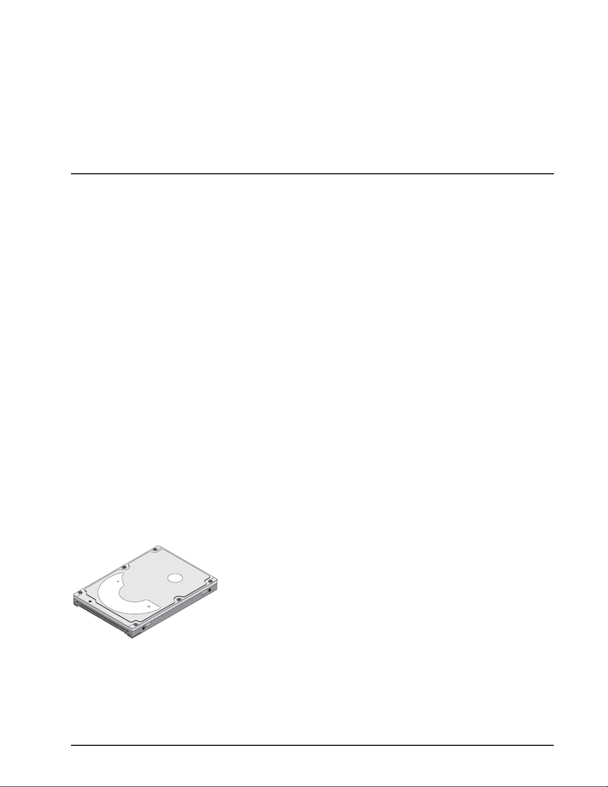
Figure 1. Momentus 5400.1 disc drive
Page 8

2
Momentus 5400.1 Product Manual, Rev. F
Page 9
Momentus 5400.1 Product Manual, Rev. F
3
2.0 Drive specifications
Unless otherwise noted, all specifications are measured under ambient conditions, at 25°C, and nominal
power. For convenience, the phrases the drive and this drive are used throughout this manual to indicate
ST94011A, ST92011A, ST92811A, and ST94811A model drives.
2.1 Specification summary
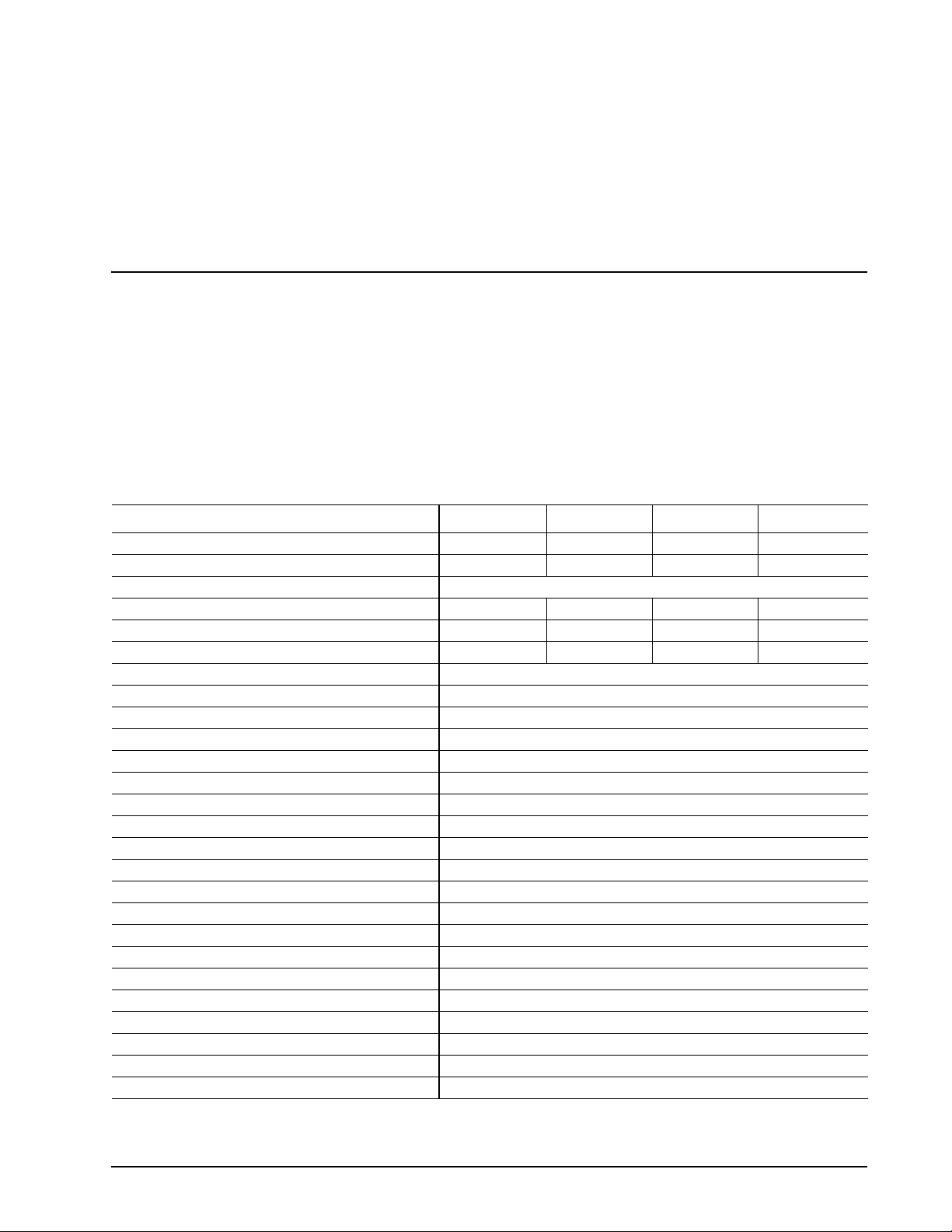
The specifications listed in this table are for quick reference. For details on specification measurement or definition, see the appropriate section of this manual.
T a ble 1: S pecifications
Drive specification ST94011A ST94811A ST92011A ST92811A
Formatted Gbytes (512 bytes/sector) 40 40 20 20
Guaranteed sectors 78,140,160 78,140,160 39,070,080 39,070,080
Bytes per sector 512
Physical read/write heads 2 2 1 1
Discs 1 1 1 1
Cache (Mbytes) 2 8 2 8
Recording density, BPI (bits/inch max) 642,000
Track density. TPI (tracks/inch max) 100,780
Areal density (Mbits/inch2 max) 65
Spindle speed (RPM) 5,400
Internal data transfer rate OD (Mbytes/sec max) 48.25
Sustained data transfer rate OD (Mbytes/sec) 34.5
I/O data-transfer rate (Mbytes/sec max) 100
ATA data-transfer modes supported PIO modes 0–4; Multiword DMA modes 0–2; Ultra DMA modes 0–5
Height 9.5 +/-0.2 mm (0.374 +/-.0078 inches)
Width 69.85 +/-0.25 mm (2.75 +/-0.0098 inches)
Length 100.2 +/-0.25 mm (3.945 +/-0.0098 inches)
Weight (typical) 99 grams (0.218 lb.)
Average latency (msec) 5.6
Power-on to ready (sec typical) 3.9
Standby to ready (sec typical) 2.6 sec
Startup current 5V (peak) 1.2 amps
Track-to-track seek time (msec typical) 1.5 (read), 2.0 (write)
Average seek time (msec typical) 12.0
Average seek, read (msec typical) 12.0
Average seek, write (msec typical) 14.0
Page 10
4
Momentus 5400.1 Product Manual, Rev. F
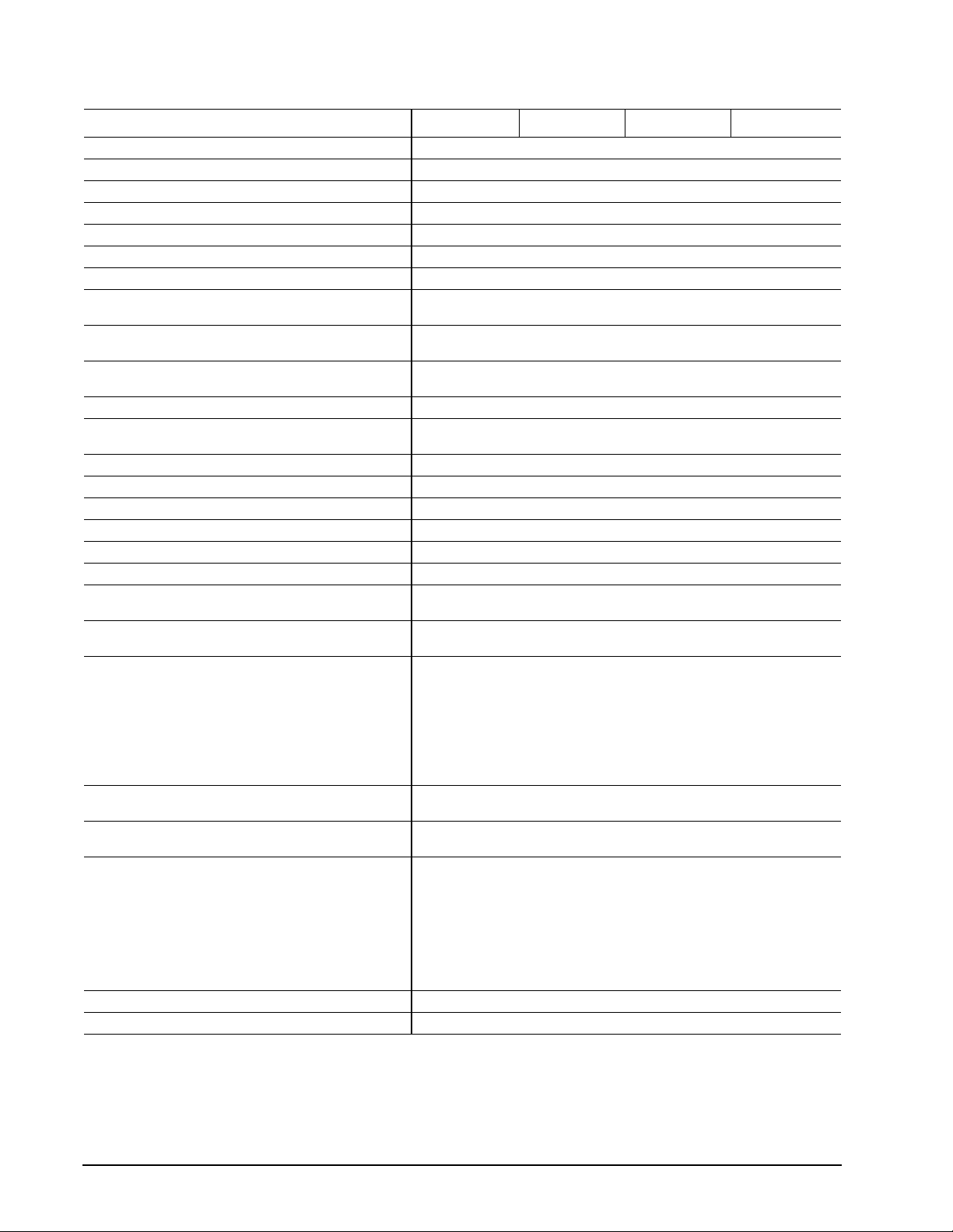
T a ble 1: S pecifications
Drive specification ST94011A ST94811A ST92011A ST92811A
Full-stroke seek (msec) 22 (typical); 26 (max)
Seek power (typical) 2.4 watts
Read/write power (typical) 2.4 watts
Idle mode (typical) 1.2 watts
Standby mode 0.36 watts (typical)**
Sleep mode 0.36 watts (typical)**
Voltage tolerance (including noise) 5V ± 5%
Ambient temperature 5° to 55°C (operating)
Temperature gradient (°C per hour max) 20°C (operating)
Relative humidity (noncondensing) 5% to 90% (operating)
Relative humidity gradient 30% per hour max
Wet bulb temperature (°C max) 33°C (operating)
Altitude, operating –192.12 m to 3,048 m (–650 ft to 10,000+ ft)
Altitude, nonoperating (below mean sea level, max) –304.8 m to 12,192 m (–1,000 ft to 40,000+ ft)
Shock, operating (Gs max at 2 msec) 225
Shock, nonoperating (Gs max at 2 msec) 800
Shock, nonoperating (Gs max at 1 msec) 800
Shock, nonoperating (Gs max at 0.5 msec) 400
Vibration, operating (max displacement may apply below
10 hz)
Vibration, nonoperating (max displacement may apply
below 22 hz)
Drive acoustics, sound power (bels)
Idle* 2.3 (typical)
Quiet seek 2.5 (typical)
Performance seek 3.0 (typical)
Nonrecoverable read errors
Mean time between failures (power-on hours) 330,000 at 25°C
Load/Unload (U/UL) cycles
25°C, 50% relative humidity
32°C, 80% relative humidity
5°C, 80% relative humidity
5°C, 10% relative humidity
55°C, 16% relative humidity
Service life 5 Y ears
Warranty 1 Y ear
–40° to 65°C (nonoperating)
30°C (nonoperating)
5% to 95% (nonoperating)
40°C (nonoperating)
1.0 Gs (0 to peak, 5–500 Hz)
5.0 Gs (0 to peak, 5–500 Hz)
2.5 (max)
2.7 (max)
3.2 (max)
1 per 1014 bits read
Max case temperature: 60°C
300,000 software-controlled power on/off cycles
20,000 hard power on/off cycles
100,000 software-controlled power on/off cycles
20,000 hard power on/off cycles
*Duri ng periods o f drive idl e, some offline activity may oc cur accord ing to the S.M.A.R.T. specification, which may increase ac oustic and
power to operational levels.
**Typical notebooks will pull power to the drive when entering S3 and S4; while in the S3 and S4 states, drive sleep and drive standby modes
will not contribute to battery power consumption.
Page 11
Momentus 5400.1 Product Manual, Rev. F
5
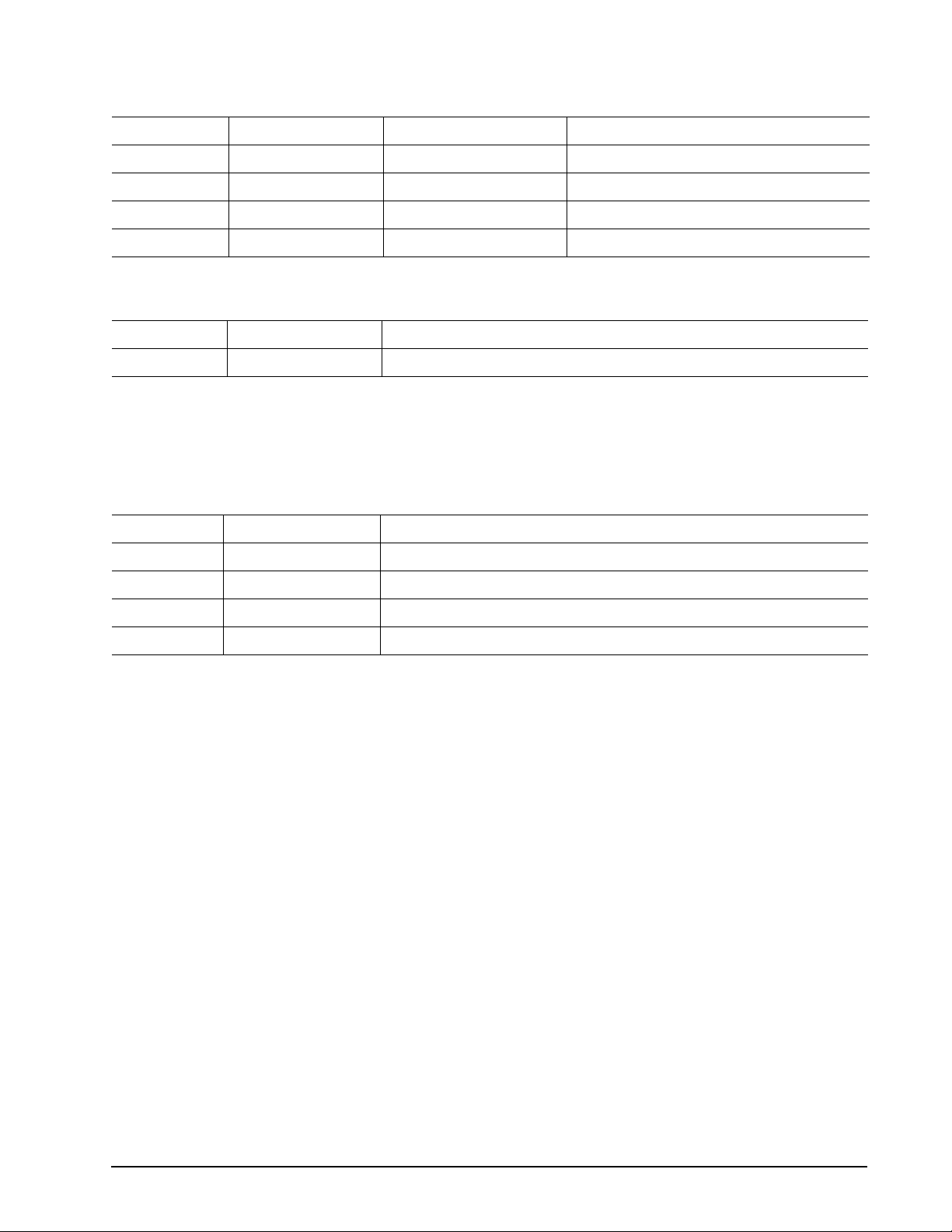
2.2 Formatted ca pacity
Model Formatted capacity Guaranteed sectors Bytes per sector
ST94011A 40 Gbytes 78,140,160 512
ST94811A 40 Gbytes 78,140,160 512
ST92011A 20 Gbytes 39,070,080 512
ST92811A 20 Gbytes 39,070,080 512
2.3 Default logi cal geometry
Cylinders Read/write heads Sectors per track
16,383 16 63
LBA mode
When addressing these drives in LBA mode, all blocks (sectors) are consecutively numbered from 0 to n–1,
where n is the number of guaranteed sectors as defined above.
2.4 Physical organization
Model Read/write heads Number of discs
ST94011A 2 1
ST94811A 2 1
ST92011A 1 1
ST92811A 1 1
Page 12
6
Momentus 5400.1 Product Manual, Rev. F
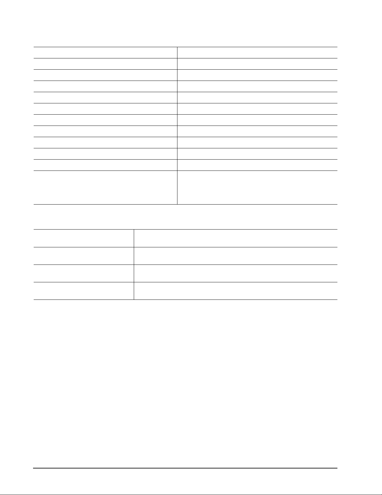
2.5 Recording and interfac e technology
Technology Specification
Interface Parallel ATA
Recording method RLL 0,11
Recording density BPI (bits/inch max) 642,000
Track density TPI (tracks/inch max) 100,780
Areal density (Mbits/inch2 max) 65
Spindle speed (RPM) (± 0.2%) 5,400
Internal data-transfer rate OD (Mbytes/sec max) 48.25
Sustained data transfer rate OD (Mbytes/sec max) 34.5
I/O data-transfer rate (Mbytes/sec max) 100 (Ultra DMA mode 5)
Interleave 1:1
Cache buffer
ST94011A and ST92011A 2 Mbytes (2,048 kbytes)
ST94811A and ST92811A 8 Mbytes (8,192 kbytes)
2.6 Physical characteristics
Height (mm)
(inches)
Width (mm)
(inches)
Length (mm)
(inches)
Typical weight (grams)
(pounds)
9.5 +/-0.2
0.374 +/-0.0078
69.85 +/-0.25
2.75 +/-0.0098
100.2 +/-0.25
3.945 +/-0.0098
99
0.218
Page 13
Momentus 5400.1 Product Manual, Rev. F
7
2.7 Seek time
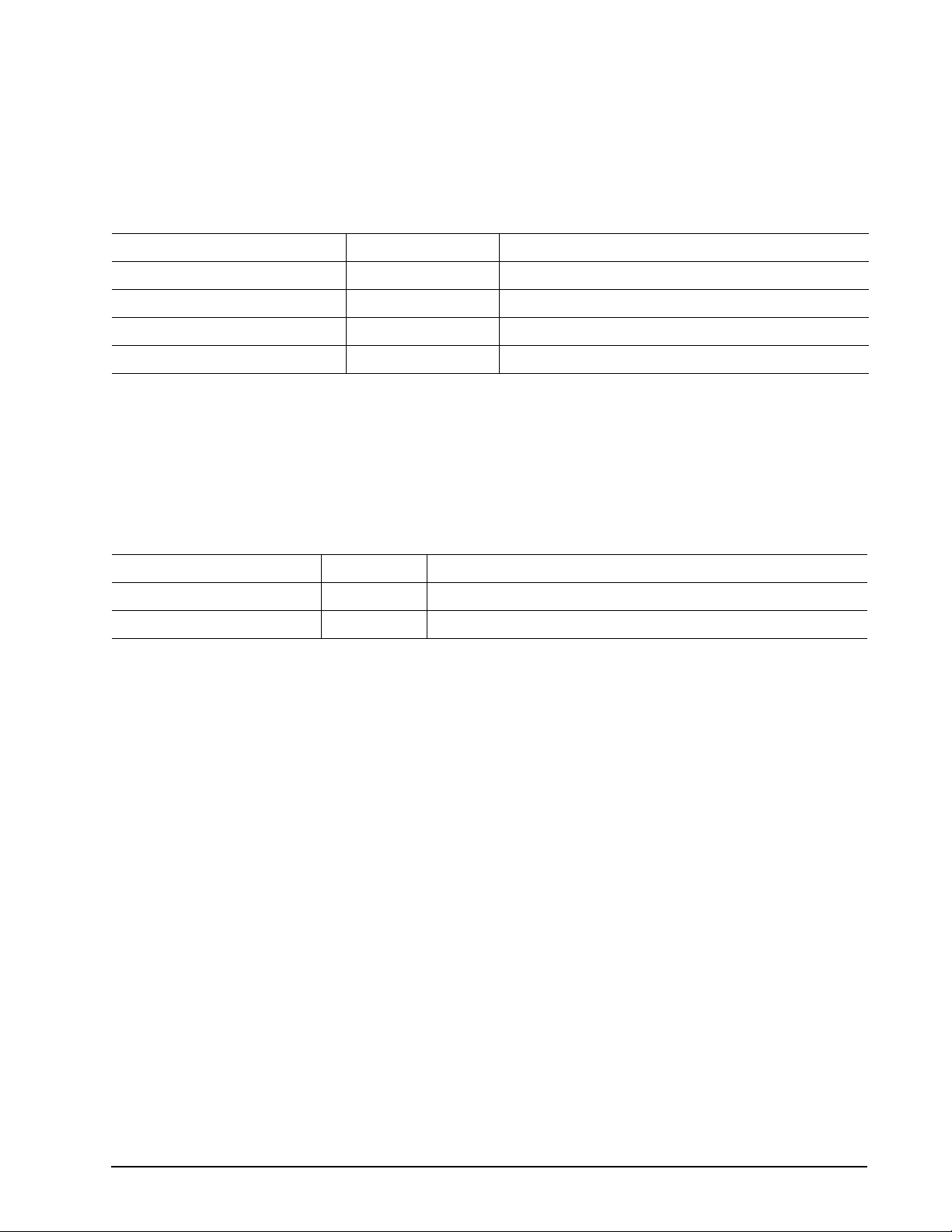
Seek measurem ent s a re t ake n wi th nom inal po w er a t 25 °C amb ient temperature. All tim es a re m easu red using
drive diagnostics. The specifications below are defined as follows:
• Track-to-track seek time is an average of all possible single-track seeks in both directions.
• Average seek time is a true statistical random average of at least 5,000 measurements of seeks between
random tracks, less overhead.
*Typical seek times (msec) Read Write
Track-to-track 1.5 2.0
Average 12.0 14.0
Full-stroke 22.0 26.0
Average latency 5.6 5.6
*Measured in performance mode
Note. These drives are designed to consistently meet the seek times represented in this manual. Physical seeks,
regardless of mode (such as track-to-track and average), are expected to meet or exceed the noted values.
However, due to the manner in which these drives are formatted, benchmark tests that include command
overhead or measure logical seeks may produce results that vary from these specifications.
2.8 Time to ready
Time to ready Typical Max
Power-on to Ready (sec) 3.9 8
St andby to Ready (sec) 2.6 8
Page 14
8
Momentus 5400.1 Product Manual, Rev. F
2.9 Power specifications
The drive receives DC power (+5V) through the interface connector.
2.9.1 Power consumption
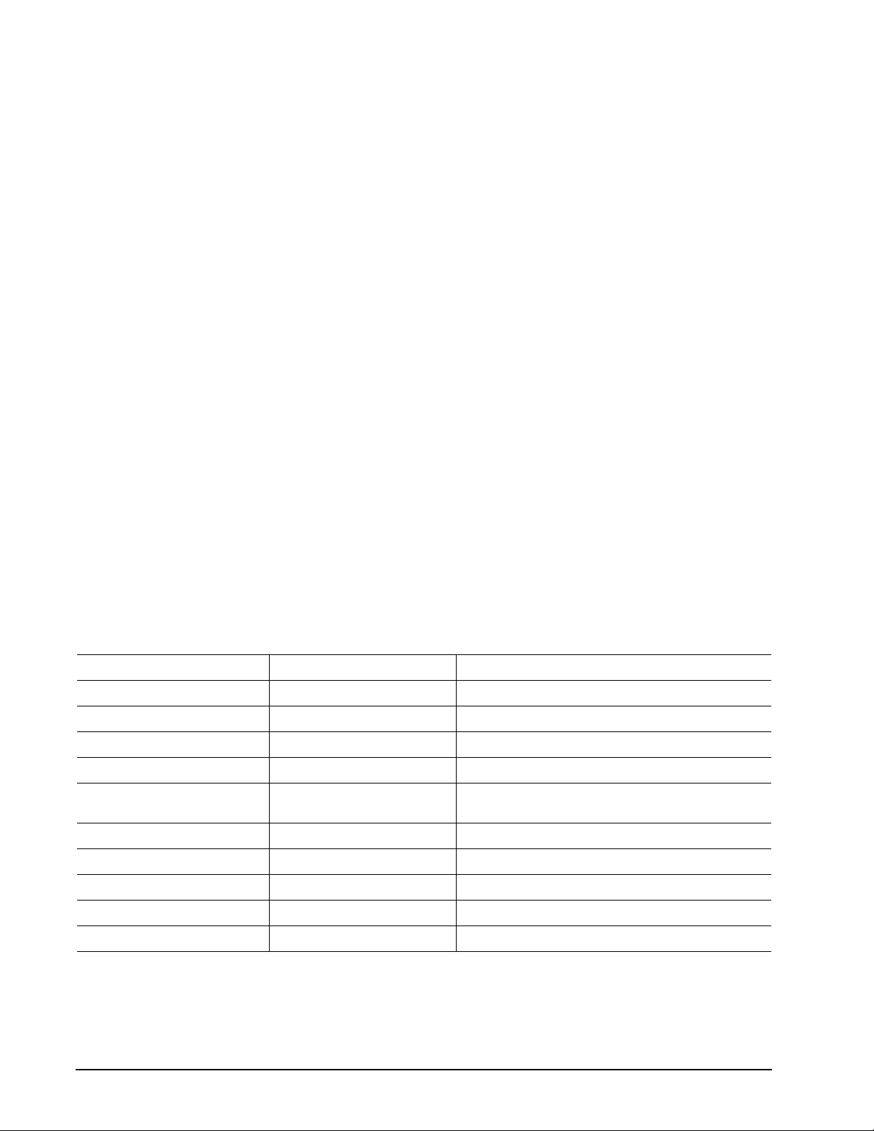
Power requiremen ts for the dr i ves are lis ted in the ta bl e on p age 8 . Typical power measurements are based on
an average of drives tested, under nominal conditions, using 5.0V input voltage at 25°C ambient temperature.
• Spinup power
S pinup power is measured from th e time of power-on to the time that the drive spindle r eaches operating speed.
• Seek mode
During seek mod e, the read /write actuator arm move s toward a spe cific positi on on the d isc surface and does
not execute a read or write operati on. Servo ele ctronics ar e acti ve. Seek mode power is mea sure d based on
three random seek operations every 100 msecs. This mode is not typical.
• Read/write power and current
Read/write power is measured with the heads on track, based on three 63 sector read or write operations
every 100 msecs.
• Operating power and current
Operating power is measured using 40 percent random seeks, 40 percent read/write mode (1 write for each
10 reads) and 20 percent drive idle mode.
• Idle mode power
Idle mode power is measured with the drive up to speed, with servo electronics active and with the heads in
a random track location.
• Standby mode
During Standby mode, the drive accepts commands, but the drive is not spinning, and the servo and read/
write electronics are in power-down mode.
T a ble 2: DC power
Power dissipation (watts) Average (watts, 25° C) 5V typ amps
Spinup — 1.2
Idle, performance mode 2.00 0.4
Idle, active 1.20 0.24
Idle, low power mode 0.97 0.19
Operating 40% r/w.
40% seek, 20% inop.
Seeking 2.4 0.48
Read 2.4 0.48
Write 2.4 0.48
Standby 0.36 0.07
Sleep 0.36 0.07
2.87
0.72
*Duri ng periods o f drive idl e, some offline activity may oc cur accord ing to the S.M.A.R.T. specification, which may increase ac oustic and
power to operational levels.
Page 15
Momentus 5400.1 Product Manual, Rev. F
9
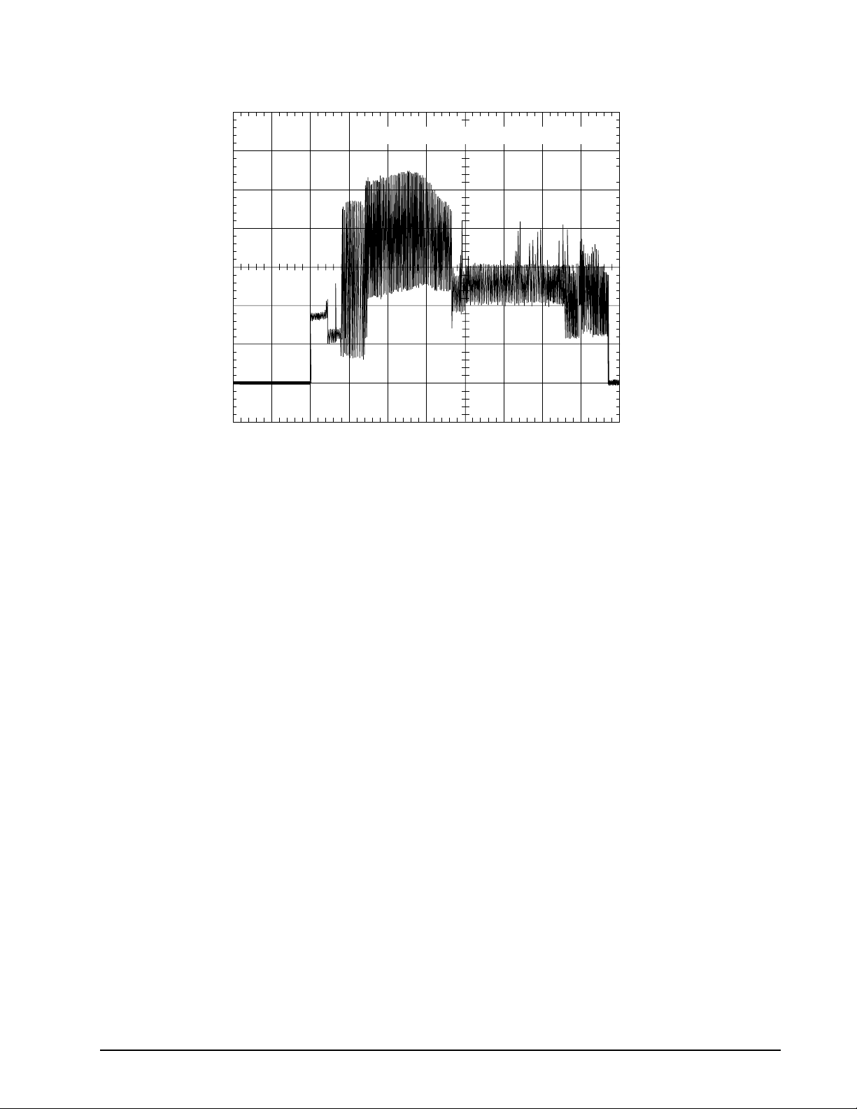
2.9.1.1 Typical current profile
A
.5
1.2
1.0
0.8
mps
0.6
0.4
0.2
0.0
+5 Volt Current during spindle start — Typical Amperes
0.0 0.5 1.0 1.5 2.0 2.5 3.0 3.5 4.0
Seconds
4
Figure 2. Typical 5V startup and operation current profile
2.9.2 Conducted noise
Input noise ripple is measured at the host system power supply across an equivalent 15-ohm resistive load on
the +5 volt line.
Using 5-volt power, the drive is expected to operate with a maximum of 100 mV peak-to-peak square-wave
injected noise at up to 10 MHz.
Note. Equivalent resistance is calculated by dividing the nominal voltage by the typical RMS read/write
current.
2.9.3 Voltage tolerance
Voltage tolerance (including noise):
5V ± 5%
Page 16
10
Momentus 5400.1 Product Manual, Rev. F
2.9.4 Power-manageme nt modes
The drive provides programmable power management to provide greater energy efficiency. In most systems,
you can control power management through the system setup program. The drive features the following
power-management modes:
Table 3: Power management modes
Power modes Heads Spindle Buffer
Active (operating) Tracking Rotating Enabled
Idle, performance Tracking Rotating Enabled
Idle, active Floating Rotating Disabled
Idle, low power Parked Rotating Disabled
Standby Parked Stopped Disabled
Sleep Parked Stopped Disabled
• Active mode
The drive is in Active mode during the read/write and seek operations.
• Idle mode
The buffer remains enabled, and the drive accepts all commands and returns to Active mode any time disc
access is necessary.
• Standby mode
The drive enters S t an dby mode when the host sends a Standby Immediate command. If the host has set the
standby timer, the drive can also enter Standby mode automatically after the drive has been inactive for a
specifiable length of time. The standby timer dela y is established using a S tandby or Idle com mand. In Sta ndby
mode, the drive buffer is enabled, the heads are parked and the spindle is at rest. The drive accepts all
commands and returns to Active mode any time disc access is necessary.
• Sleep mode
The drive enters Slee p mo de after receiving a Slee p com mand from the host. I n Sle ep m ode, the dr ive bu ffer
is disabled, the heads are parked and the spindle is at rest. The drive leaves Sleep mode after it receives a
Hard Reset or Sof t Reset from the host. A fter receivi ng a reset, the drive exit s Sleep mode and enters S tandby
mode with all current translation parameters intact.
• Idle and Standby timers
Each time the drive performs an Active function (read, write or seek), the standby timer is reinitialized and
begins counting down fr om its specified del ay times to zero. If the stand by timer reaches zero before an y drive
activity is required, the drive makes a transition to Standby mode. In both Idle and Standby mode, the drive
accepts all commands and returns to Active mode when disc access is necessary.
Page 17
Momentus 5400.1 Product Manual, Rev. F
11
2.10 Environmental specifications
2.10.1 Ambient temperature
Ambient temperature is defined as the temperature of the environment immediately surrounding the drive.
Actual drive case temperature should not exceed 60°C (140°F) within the operating ambient conditions.
Above 1,000 feet (305 meters), the maximum temperature is derated linearly by 1°C every 1000 feet.
Operating 5° to 55°C (41° to 131°F)
Nonoperating –40° to 65°C (–40° to 149°F)
2.10.2 Temperature gradient
Operating 20°C per hour (68°F per hour max), without condensation
Nonoperating 30°C per hour (86°F per hour max)
2.10.3 Humidity
2.10.3.1 Relative humidity
Operating 5% to 90% noncondensing (30% per hour max)
Nonoperating 5% to 95% noncondensing (30% per hour max)
2.10.3.2 Wet bulb temperature
Operating 33°C (91.4°F max)
Nonoperating 40°C (104°F max)
2.10.4 Altitude
Operating –198.12 m to 3,048 m (–650 ft to 10,000+ ft)
Nonoperating –304.8 to 12,192 m (–1,000 ft to 40,000+ ft)
Page 18
12
Momentus 5400.1 Product Manual, Rev. F
2.10.5 Shock
All shock specifications assume that the drive is mounted securely with the input shock applied at the drive
mounting screws. Shock may be applied in the X, Y or Z axis.
2.10.5.1 Operating shock
These drives comply with the performance levels specified in this document when subjected to a maximum
operating shock of 225 Gs based on half-sine shock pulses of 2 msec. Shocks should not be repeated more
than two times per second.
2.10.5.2 Nonoperatin g sho ck
The nonoperating shock level that the drive can experience without incurring physical damage or degradation
in performance when subsequently put into operation is 80 0 Gs based o n a nonr epetitive hal f-sine shock pulse
of 2 msec duration.
The nonoperating shock level that the drive can experience without incurring physical damage or degradation
in performance when subsequently put into operation is 80 0 Gs based o n a nonr epetitive hal f-sine shock pulse
of 1 msec duration.
The nonoperating shock level that the drive can experience without incurring physical damage or degradation
in performance when subsequently put into operation is 40 0 Gs based o n a nonr epetitive hal f-sine shock pulse
of 0.5 msec duration.
2.10.6 Vibration
All vibration specifications assume that the drive is mounted securely with the input vibration applied at the
drive mounting screws. Vibration may be applied in the X, Y or Z axis.
2.10.6.1 Operating vibration
The following table lists the maximum vibration levels that the drive may experience while meeting the performance standards specified in this document.
5–500 Hz 1.0 Gs (0 to peak). Max displacement may apply below 10 Hz.
2.10.6.2 Nonoperatin g vibr ati on
The following table lists the maximum nonoperating vibration that the drive may experience without incurring
physical damage or degradation in performance when subsequently put into operation.
5–500 Hz 5.0 Gs (0 to peak). Max displacement may apply below 22 Hz.
Page 19
Momentus 5400.1 Product Manual, Rev. F
13
2.11 Acoustics
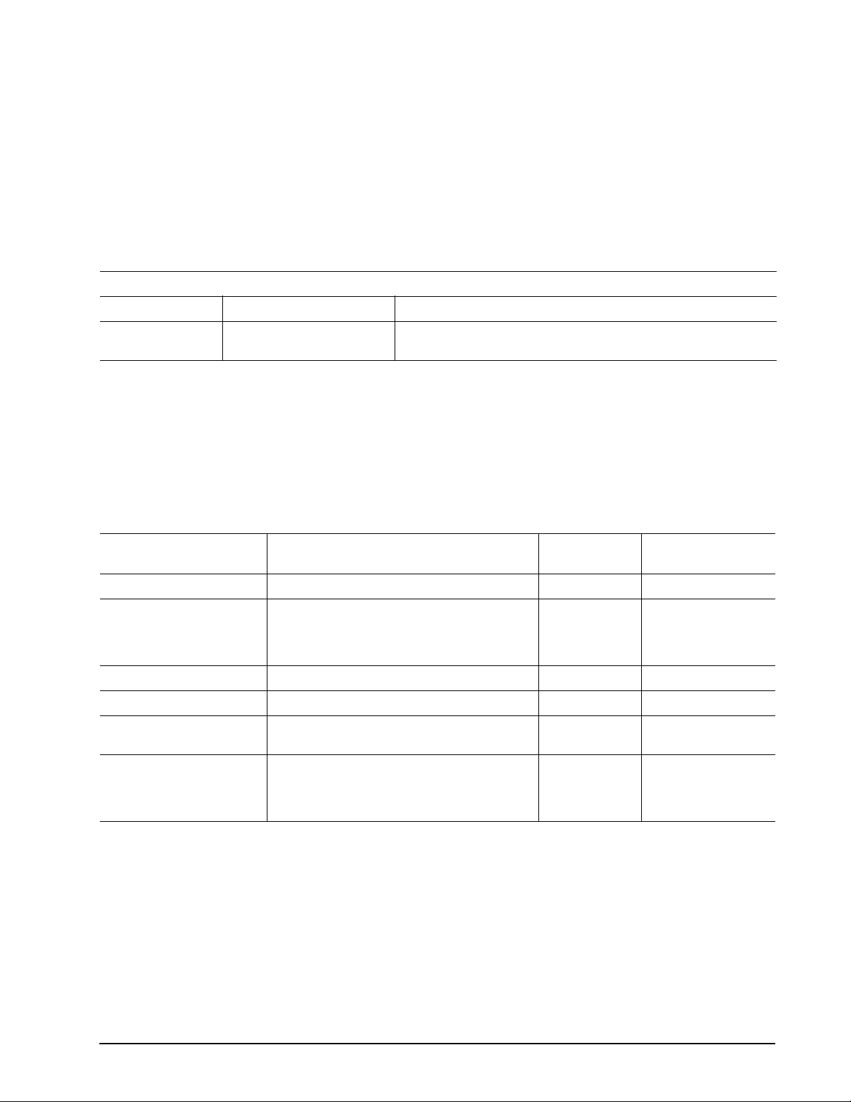
Drive acoustics are measured as overall A-weighted acoustic sound power levels (no pure tones). All measurements are consistent with ISO document 7779. Sound power measurements are taken under essentially
free-field conditions over a reflecting plane. For all tests, the drive is oriented with the cover facing upward.
Note. For seek mode tests, the drive is pl aced in seek mode only . T he number of seeks pe r second is defined
by the following equation:
(Number of seeks per second = 0.4 / (average latency + average access time)
Table 4: Drive level acoustics
Acoust ic m ode
Idle* Quiet Seek Performance Seek
2.3 bels (typ)
2.5 bels (max)
*Duri ng periods o f drive idl e, some offline activity may occur acc ording to the S.M.A.R.T. specification, which m ay increas e acousti c and
power to operational levels.
2.5 bels (typ)
2.7 bels (max)
3.0 bels (typ)
3.2 bels (max)
2.12 Electromagnetic immunity
When properly installed in a representative host system, the drive operates without errors or degradation in
performance when subjected to the radio frequency (RF) environments defined in the following table:
T a ble 5: Elect roma gn etic immun ity
Performance
Test Description
Electrostatic discharge Contact, HCP, VCP: ± 4 kV; Air: ± 8 kV B EN 61000-4-2: 95
Radiated RF immunity 80 to 1,000 MHz, 3 V/m,
80% AM with 1 kHz sine
900 MHz, 3 V/m, 50% pulse modulation @ 200
Hz
Electrical fast transient ± 1 kV on AC mains, ± 0.5 kV on external I/O B EN 61000-4-4: 95
Surge immunity ± 1 kV differential, ± 2 kV common, AC mains B EN 61000-4-5: 95
Conducted RF immunity 150 kHz to 80 MHz, 3 V rm s, 80% AM with 1
kHz sine
level
A EN 61000-4-3: 96
A EN 61000-4-6: 97
Reference
standard
ENV 50204: 95
Voltage dips, interrupts 0% open, 5 seconds
0% short, 5 seconds
40%, 0.10 seconds
70%, 0.01 seconds
C
C
C
B
EN 61000-4-11: 94
Page 20
14
Momentus 5400.1 Product Manual, Rev. F
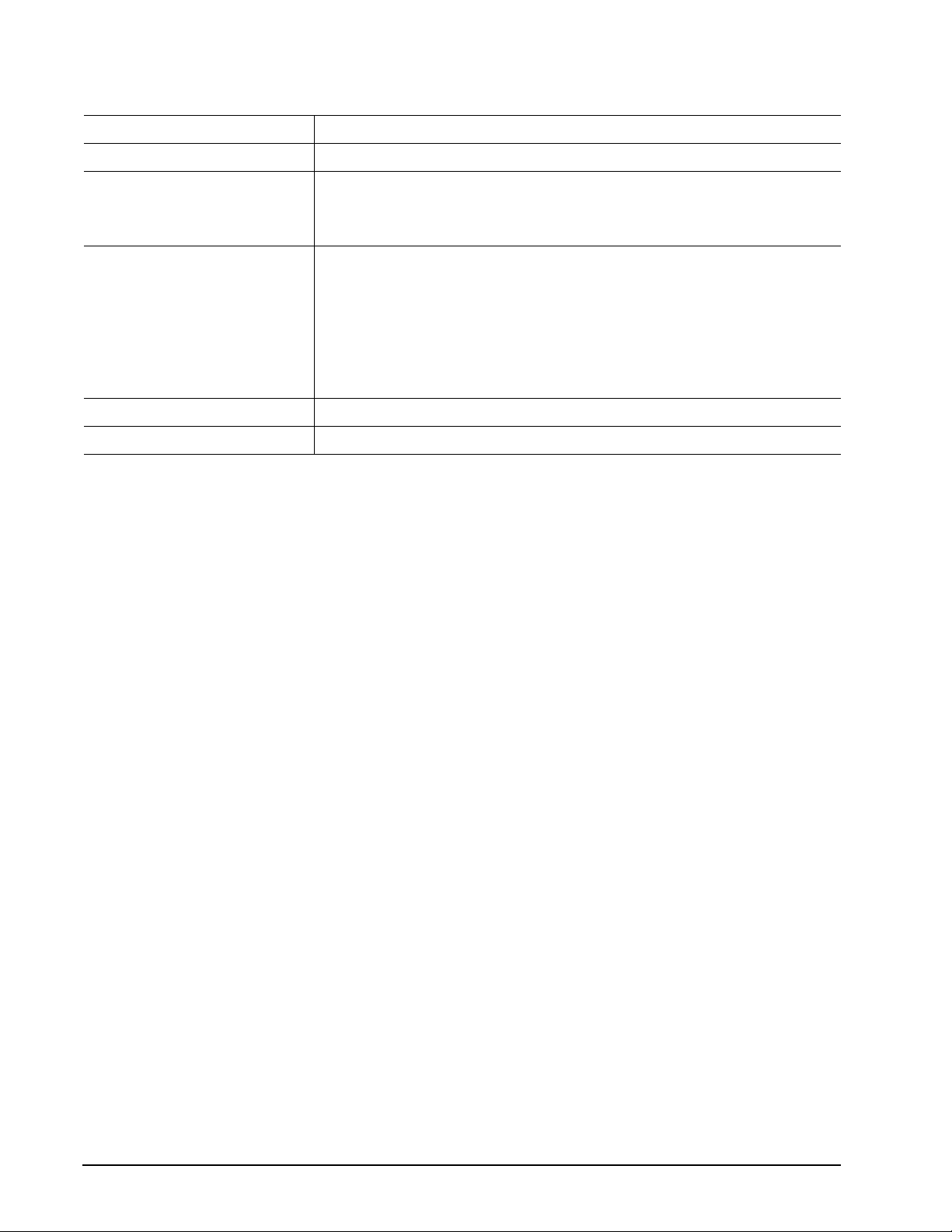
2.13 Reliability
Measurement type Specification
Nonrecoverable read errors 1 per 1014 bits read, max.
Mean time between failures 330,000 power-on hours
At nominal power, 25°C ambient temperature.
Max case temperature: 60°C at the case measurement location shown in Figure
4.
Load/Unload (U/UL)
25°C, 50% relative humidity
32°C, 80% relative humidity
5°C, 80% relative humidity
5°C, 10% relative humidity
55°C, 16% relative humidity
Service Life 5 Years
Warranty 1 Year
300,000 software-controlled power on/off cycles
20,000 hard power on/off cycles
100,000 software-controlled power on/off cycles
20,000 hard power on/off cycles
2.14 Agency certifica tion
2.14.1 Safety certification
The drives are recognized in accordance with UL 1950 and CSA C22.2 (950) and meet all applicable sections
of IEC950 and EN 60950 as tested by TUV North America.
2.14.2 Electroma gnetic compatibility
Hard drives that displ ay th e CE mark com pl y wit h the Euro pean Union (EU) requirements specified in the Elec tromagnetic Compatibility Directive (89/336/EEC). Testing is performed to the levels specified by the product
standards for Information Technology Equipment (ITE). Emission levels are defined by EN 55022, Class B and
the immunity levels are defined by EN 55024.
Seagate uses an inde pend ent laboratory to confirm compl ian ce with the EC directives specified i n t he pr evious
paragraph. Drives are teste d in representa tive end-user systems. Although CE-marked Seagate drives comply
with the directives when used in the test systems, we cannot guarantee that all systems will comply with the
directives. The drive is designed for operation inside a properly designed enclosure, with properly shielded I/O
cable (if necessary) and terminators on all unused I/O ports. Computer manufacturers and system integrators
should confirm EMC compliance and provide CE marking for their products.
Page 21

Momentus 5400.1 Product Manual, Rev. F
15
Korean RRL
If these drives have the Korea Ministry of Information and Communication (MIC) logo, they comply with paragraph 1 of Article 11 of the Electromagnetic Compatibility control Regulation and meet the Electromagnetic
Compatibility (EMC) Framework requirements of the Radio Research Laboratory (RRL) Ministry of Information
and Communication Republic of Korea.
These drives have been tested and com ply with the Electr omag netic Inter fere nce/E lectro magn etic Susce ptibility (EMI/EMS) for Class B products. Drives ar e tested in a representative, end-user system by a Korean-recognized lab.
• EUT name (model numbers): ST94011A. ST92011A, ST94811A and ST92811A
• Certificate numbers:
ST94011A E-H011-03-1191(B)
ST92011A E-H011-03-1192(B)
ST94811A E-H011-03-1189(B)
ST92811A E-H011-03-1190(B)
• Trade name or applicant: Seagate Technology
• Manufacturing date: April 2003
• Manufacturer/nationality: USA, Singapore and China
Australian C-Tick (N176)
If these models have the C-Tick marking, they comply with the Australia/New Zealand Standard AS/NZS3548
1995 and meet the Electromagnetic Compatibility (EMC) Framework requirements of the Australian Communication Authority (ACA).
2.14.3 FCC verification
These drives are intended to be cont ai ned solely w ithin a person al compute r or similar enclosu re (no t attached
as an external device ). As su ch, ea ch dr ive is co nsidere d to be a suba ssembly even when it is individually mar keted to the customer. As a subassembly, no Federal Communications Commission verification or certification
of the device is required.
Seagate Technology LLC has tested this device in enclosures as described above to ensure that the total
assembly (enclosure, disc drive, motherboard, power supply, etc.) does comply with the limits for a Class B
computing device, pursuant to Subpart J, Part 15 of the FCC rules. Operation with noncertified assemblies is
likely to result in interference to radio and television reception.
Radio and television interference. This equipment generates and uses radio frequency energy and if not
installed and used in strict accordance with the manufacturer’s instructions, may cause interference to radio
and television reception.
This equipment is designed to provide reasonable protection against such interference in a residential installation. However , there is no guarantee that interfer ence will not occur in a particular inst allation. If this equipm ent
does cause interference to radio or television, which can be determined by turning the equipment on and off,
you are encouraged to try one or more of the following corrective measures:
• Reorient the receiving antenna.
• Move the device to one side or the other of the radio or TV.
• Move the device farther away from the radio or TV.
• Plug the computer into a different outlet so that the receiver and computer are on different branch outlets.
Page 22

16
Momentus 5400.1 Product Manual, Rev. F
If necessary, you should consult your dealer or an experienced radio/television technician for additional suggestions. You may find helpful the following booklet prepared by the Federal Communications Commission:
How to Identify and Resolve Radio-Television Interference Problems. This booklet is available from the Superintendent of Documents, U.S. Government Printing Office, Washington, DC 20402. Refer to publication number 004-000-00345-4.
Page 23

Momentus 5400.1 Product Manual, Rev. F
17
3.0 Configuring and mounting the drive
This section contains the specifications and instructions for configuring and mounting the drive.
3.1 Handling and static discharge precautions
After unpacking, and before installation, the drive may be exposed to potential handling and electrostatic discharge (ESD) hazards. Observe the following standard handling and static-discharge precautions:
Caution:
• Keep the drive in the electrostatic discharge (ESD) bag until you are ready for installation to limit the drive’s
exposure to ESD.
• Before handling the drive, put on a grounded wrist strap, or ground yourself frequently by touching the metal
chassis of a computer that is plugge d into a grounded outlet. We ar a grounded wrist strap through out the entire
installation procedure.
• Handle the drive only by its edges or frame.
• The drive is fragile—handle it with care. Do not press down on the drive top cover.
• Always rest the drive on a padded, antistatic surface until you mount it in the computer.
• Do not touch the connector pins or the printed circuit board.
• Do not remove the factory-installed labels from the drive or cover them with additional labels. Removal voids
the warranty. Some factory-installed labels contain information needed to service the drive. Other labels are
used to seal out dirt and contamination.
3.2 Jumper setti ngs
3.2.1 Master/slave configuration
Use the options jumper block shown in Figure 3 to configure the drive for operation. This jumper block is the 4pin header adjacent to pins 1 and 2 of the I/O signal pins. For additional information about using the Cable
select option, see section 3.2.2.
The “Master or single drive” option is the factory default setting.
Drive is master (or single drive)
Drive is slave
Cable select
Figure 3. Jumper settings
Page 24
18
Momentus 5400.1 Product Manual, Rev. F
3.2.2 Cable-select option
Computers that use cable select determine the master and slave drives by selecting or deselecting pin 28,
CSEL, on the interface bus. Master and slave drives are determined by their physical position on the cable. To
enable cable select, set a jumper as shown in Figure 3. Refer to your computer manual to determine whether
your computer supports this option.
3.3 Drive mounting
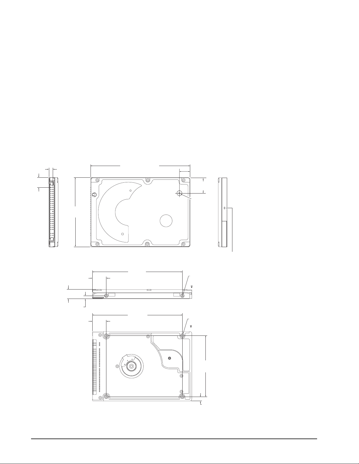
You can mount the drive using four screws in the side-mounting holes or four screws in the bottom-mounting
holes. See Figure 4 for drive mounting di m ensions. Follow these i mpo rt ant mo unting pr ecauti o ns when mou nting the drive:
• Allow a minimum clearance of 0.030 inches (0.76 mm) around the entire perimeter of the drive for cooling.
• Use only M3 UNC mounting screws.
• Do not overtighten the mounting screws (maximum torque: 4.0 inch-lb).
• Four (4) threads (0.080 inches) minimum screw engagement recommended.
3.945 +/-0.0098
(100.2 +/-.25)
0.490 +/- .010
(12.446 +/- .254)
0.680 +/- .010
(17.27 +/- .254)
Breather Hole
Do not cover
or seal.
.399
(10.135)
.157
(3.9878)
2.750 +/- .0098
(69.85 +/- .25)
inches
(mm)
3.567
(90.602)
3.567
(90.60)
.374 +/- .0078
(9.5 +/- .2)
Both sides
2X .118
.551
(13.99)
.551
(13.99)
Figure 4. Mounting dimens ions—top, side and e nd v ie w
Recommended case
temp. measurement location
2X M3 X 0.5-6H
Mounting holes
Both sides
.12 min. full thread
4X M3 X 0.5-6H
Mounting holes
.10 min. full thread
2.430
(61.722)
.160
(4.06)
Page 25
Momentus 5400.1 Product Manual, Rev. F
19
4.0 ATA interface
These drives use the industry-standard ATA task file interface that supports 16-bit data transfers. It supports
ATA programmed input/output (PIO) modes 0–4; multiword DMA modes 0–2, and Ultra DMA modes 0–5. The
drive also supports the use of the IORDY signal to provide reliable high-speed data transfers.
For detailed information about the ATA interface, refer to the draft of AT Attachment with Packet Interface
Extension (ATA/ATAPI-6), NCITS T13 1410D, subsequently referred to as the Draft ATA-6 Standard.
4.1 ATA interface signals and connector pins
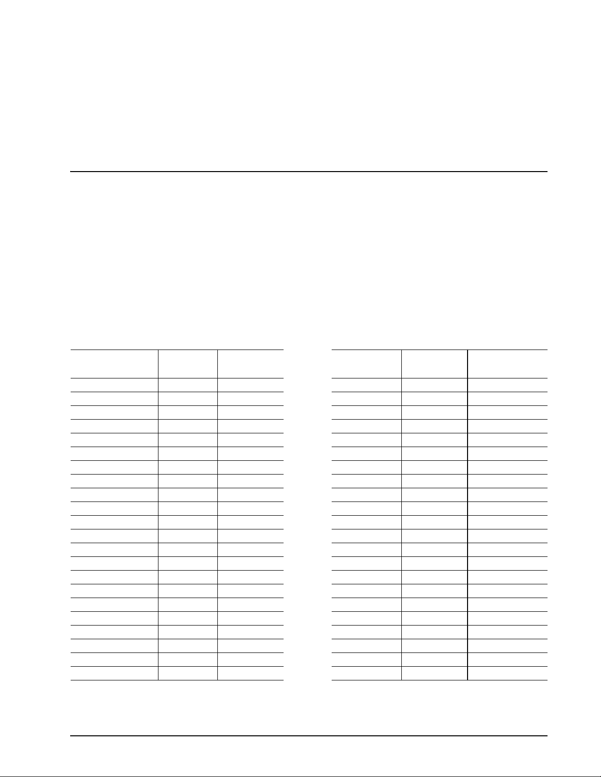
The following tab le summa rizes the sign als on the 44 -pin ATA interface connector. For a de ta iled descr ipti on of
these signals, refer to the Draft ATA-6 Standard.
T a ble 6: Conn ecto r sign als
Connector
Signal Name
RESET- 1 1 2 2 Ground
DD7 3 3 4 4 DD8
DD6 5 5 6 6 DD9
DD5 7 7 8 8 DD10
DD4 9 9 10 10 DD11
DD3 11 11 12 12 DD12
DD2 13 13 14 14 DD13
DD1 15 15 16 16 DD14
DD0 17 17 18 18 DD15
Ground 19 19 20 20 (keypin)
DMARQ 21 21 22 22 Ground
DIOW- 23 23 24 24 Ground
DIOR- 25 25 26 26 Ground
IORDY 27 27 28 28 PSYNC:CSEL
DMACK- 29 29 30 30 Ground
INTRQ 31 31 32 32 IOCS16DA1 33 33 34 34 PDIAGDA0 35 35 36 36 DA2
CS1FX- 37 37 38 38 CS3FXDASP- 39 39 40 40 Ground
+5 V (Logic) 41 41 42 42 +5V (Motor)
Ground (Return) 43 43 44 44 No connection
Contact
Cable
Conductor
Cable
Conductor
Connector
Contact
Signal Name
Page 26
20
Momentus 5400.1 Product Manual, Rev. F
4.1.1 Supported ATA commands
The following table lists ATA-standard commands that the drive supports. For a detailed description of the ATA
commands, refer to the Draft ATA-6 Standard. See “S.M.A.R.T. commands” on page 27. for details and sub-
commands used in the S.M.A.R.T. implementation.
T a bl e 7: Suppo rt ed com ma nds
Command nam e Command code (in hex)
A TA-standard commands
ATA Device Configuration Overlay B1
ATA Service A2
Check Power Mode 98
Download Microcode 92
Execute Device Diagnostics 90
Flush Cache E7
Flush Cache Extended EA
Format Track (Legacy) 50
Identify Device EC
Idle 97
Idle Immediate 95
Initialize Device Parameters 91
Read Buffer E4
Read DMA C8
Read DMA Extended 25
Read Log Extended 22
Read Multiple C4
Read Multiple Extended 29
Read Native Max Address F8
Read Native Max Address Extended 27
Read Sectors 20
Read Sectors Extended 24
Read Verify Sectors 40
Read Verify Sectors Extended 42
Recalibrate 10
Security Disable Password F6
Security Erase Prepare F3
Security Erase Unit F4
Security Freeze Lock F5
Security Set Password F1
H
H
H, E5H
H
H
H
H
H
H
H, E3H
H, E1H
H
H
H, C9H
H
H
H
H
H
H
H, 21H
H
H, 41H
H
H
H
H
H
H
H
Page 27
Momentus 5400.1 Product Manual, Rev. F
21
T a bl e 7: Suppo rt ed com ma nds
Command name Command code (in hex)
Securit y Un l o ck F2
Seek 70
Set Drive Parameters 91
Set Features EF
Set Max Address F9
Note: Individual Set Max commands are identified by the value
placed in the Set Max Features
register as defined to the right.
H
H
H
H
H
Address:
Password:
Lock:
Unlock:
Freeze Lock:
Set Multiple Mode C6
Sleep 99
S.M.A.R.T. B0
Standby 96
St andby Immediate 94
Vendor Unique 9A
Write Buffer E8
Write DMA CA
Write DMA Extended 35
Write Log Extended 32
Write Multiple C5
Write Multiple Extended 39
Write Sectors 30
Write Sectors Extended 34
H
H, E6H
H
H, E2H
H, E0H
H, FAH, FBH
H
H, CBH
H
H
H
H
H, 31H
H
ATA-st a ndard powe r- m a nagement c om m a nds
00
01
02
03
04
H
H
H
H
H
Check Power Mode 98H or E5
Idle 97H or E3
Idle Immediate 95H or E1
Sleep 99H or E6
Standby 96H or E2
St andby Immediate 94H or E0
A TA-standard security commands
Security Set Password F1
Securit y Un l o ck F2
Security Erase Prepare F3
Security Erase Unit F4
H
H
H
H
H
H
H
H
H
H
Page 28
22
Momentus 5400.1 Product Manual, Rev. F
T a bl e 7: Suppo rt ed com ma nds
Command name Command code (in hex)
Security Freeze Lock F5
Security Disable Password F6
H
H
Page 29
Momentus 5400.1 Product Manual, Rev. F
23
4.1.2 Identify Device command
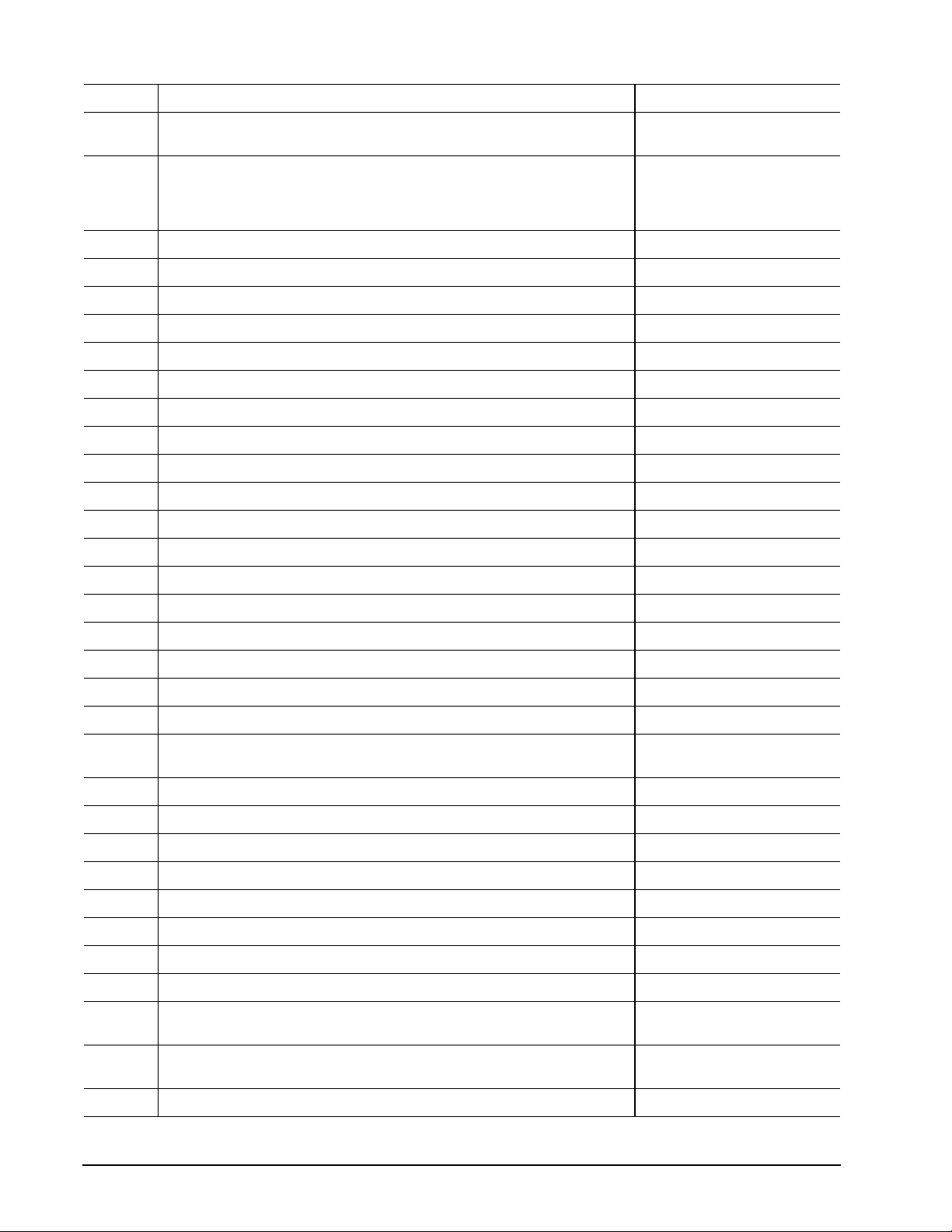
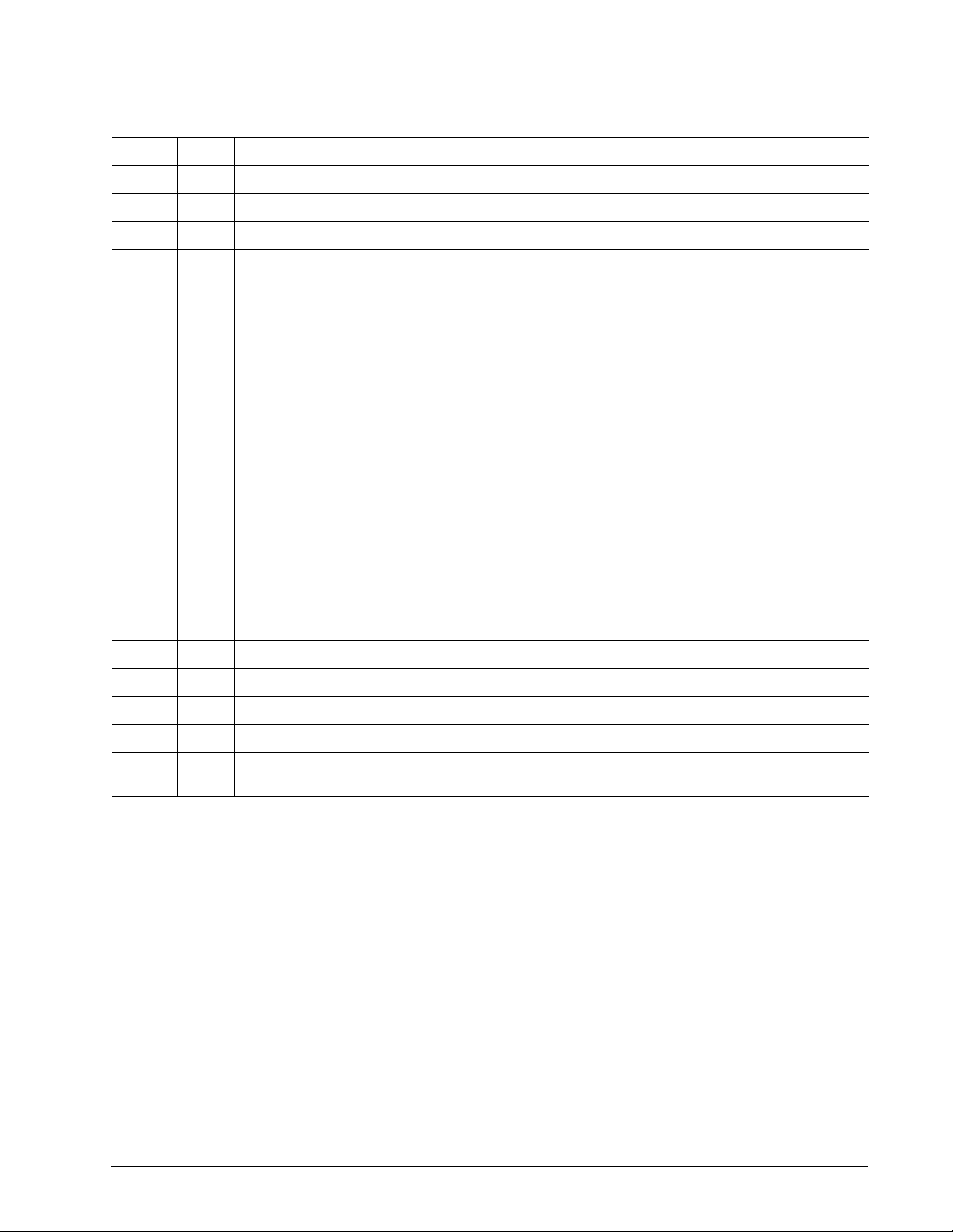
The Identify Device command (command code ECH) transfers information about the drive to the host following
power up. The data is organized as a single 512-byte block of data, whose contents are shown in the table on
page 27. All reserved bits or words should be set to zero. Parameters listed with an “x” are drive-specific or
vary with the state of the drive. See Section 2.0 on page 3 for default parameter settings.
The following commands conta in drive-specific features that may not be included in the Draf t AT A-6 Standard.
Word Description Value
0
Configuration information:
• Bit 15: 0 = ATA; 1 = ATAPI
• Bit 7: removable media
0C5A
• Bit 6: removable controller
• Bit 0: reserved
1 Number of logical cylinders 16,383
2 ATA-reserved 0000
H
3 Number of logical heads 16
4 Retired 0000
5 Retired 0000
6 Number of logical sectors per logical track: 63 003F
7–9 Retired 0000
H
H
H
H
10–19 Serial number: (20 ASCII characters, 0000H = none) ASCII
20 Retired 0000
21 Retired 0400
22 Obsolete 0000
23–26 Firmware revision
H
H
H
x.xx
(8 ASCII character string, padded with blanks to end of string)
27–46 Drive model number: (40 ASCII characters, padded with blanks to end of
string)
ST94011A
ST92011A
ST94811A
ST92811A
H
47 (Bits 7–0) Maximum sectors per interrupt on Read multiple and Write mul-
tiple (16)
48 Reserved 0000
49 Standard Standby timer, IORDY supported and may be disabled 2F00
50 ATA-reserved 0000
51 PIO data-trans fer cycle timing mode 0200
52 Retired 0200
53 Words 54–58, 64–70 and 88 are valid 0007
54 Number of current logical cylinders xxxx
55 Number of current logical heads xxxx
56 Number of current logical sectors per logical track xxxx
57–58 Current capac ity in sectors xxxx
8010
H
H
H
H
H
H
H
H
H
H
H
Page 30
24
Momentus 5400.1 Product Manual, Rev. F
Word Description Value
59 Number of sectors transferred during a Read Multiple or Write Multiple
xxxx
command
60–61 Total number of user-addressable LBA sectors available
(see Section 2.2 for related information)
ST94011A = 78,140,160
ST92011A = 39,070,080
ST94811A = 78,140,160
ST92811A = 39,070,080
62 Retired 0000
63 Multiword DMA active and modes supported (see note following this table) xx07
64 Advanced PIO modes supported (modes 3 and 4 supported) 0003
65 Minimum multiword DMA transfer cycle time per word (120 nsec) 0078
66 Recommended multiword DMA transfer cycle time per word (120 nsec) 0078
67 Minimum PIO cycle time without IORDY flow control (240 nsec) 00F0
68 Minimum PIO cycle time with IORDY flow control (120 nsec) 0078
69–74 ATA-reserved 0000
75 Queue depth 0000
76–79 ATA-reserved 0000
80 Major version number 007E
81 Minor version number 0000
82 Command sets supported 346B
83 Command sets supported 7D09
84 Command sets support extension 4003
85 Command sets enabled 34xx
86 Command sets enabled 3xxx
87 Command sets enable extension 4003
88 Ultra DMA support and current mode
xx3F
(see note following this table)
H
H
H
H
H
H
H
H
H
H
H
H
H
H
H
H
H
H
H
H
89 Security erase time 0000
90 Enhanced security erase time 0000
91 Advanced power management value 0040
92 Master password revision code FFFE
93 Hardware reset value (see description following this table) xxxx
94 Auto acoustic management setting xxxx
95–127 ATA-reserved 0000
128 Secur i ty status 0001
129–
Seagate-reserved xxxx
159
160–
ATA-reserved 0000
254
255 Integrity word xxA5
H
H
H
H
H
H
H
H
H
H
H
Page 31
Momentus 5400.1 Product Manual, Rev. F
25
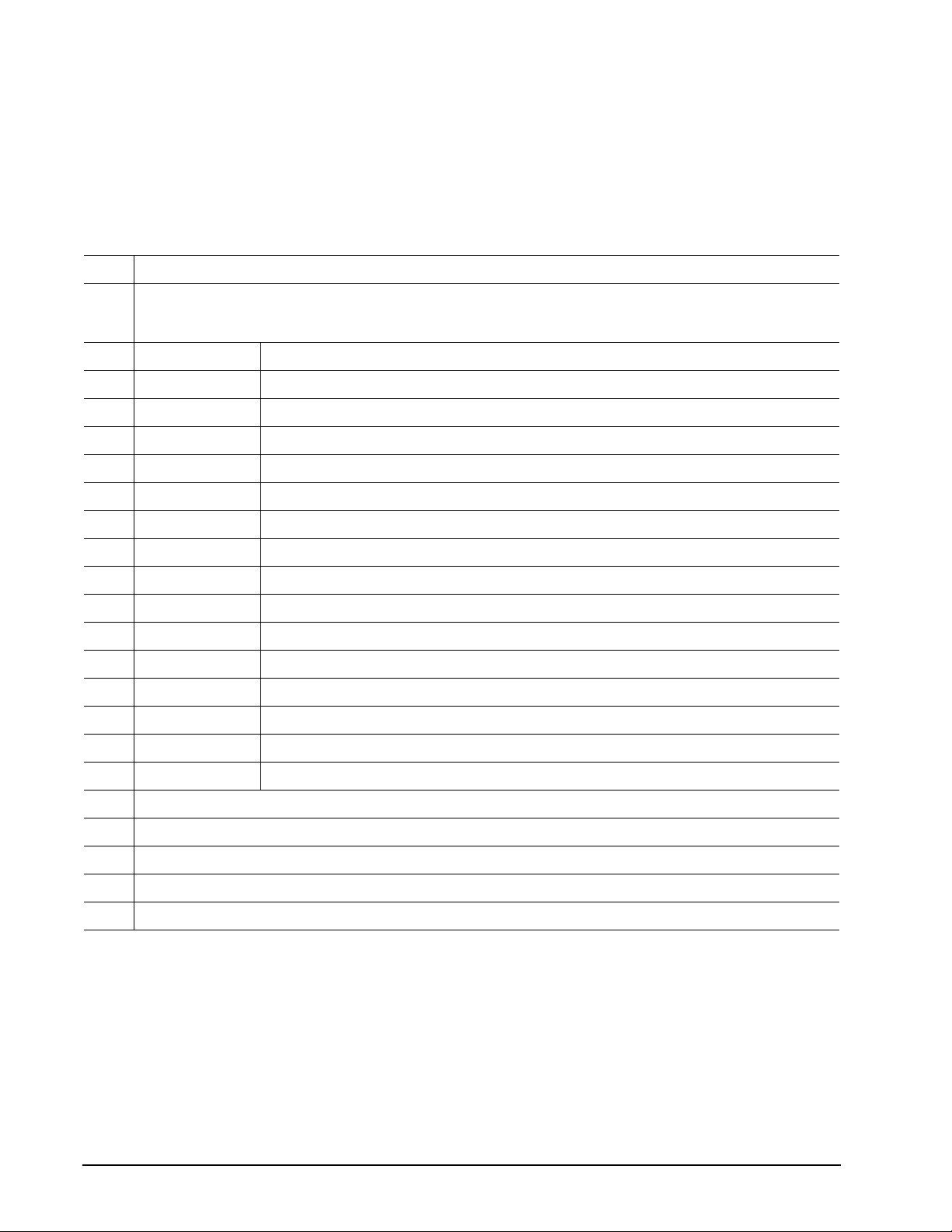
Note. See the bit descriptions below for words 63, 88, 93 and 94 of the Identify Drive data:
Description (if bit is set to 1)
Bit Word 6 3
0 Multiword DMA mode 0 is supported.
1 Multiword DMA mode 1 is supported.
2 Multiword DMA mode 2 is supported.
8 Multiword DMA mode 0 is currently active.
9 Multiword DMA mode 1 is currently active.
10 Multiword DMA mode 2 is currently active.
Bit Word 8 8
0 Ultra DMA mode 0 is supported.
1 Ultra DMA mode 1 is supported.
2 Ultra DMA mode 2 is supported.
3 Ultra DMA mode 3 is supported.
4 Ultra DMA mode 4 is supported.
8 Ultra DMA mode 0 is currently active.
9 Ultra DMA mode 1 is currently active.
10 Ultra DMA mode 2 is currently active.
11 Ultra DMA mode 3 is currently active.
12 Ultra DMA mode 4 is currently active.
13 Ultra DMA mode 5 is currently active.
Bit Word 9 3
13 1 = 80-conductor cable detected, CBLID above VIH
0 = 40-conductor cable detected, CBLID below VIL
Page 32
26
Momentus 5400.1 Product Manual, Rev. F
4.1.3 Set Features command
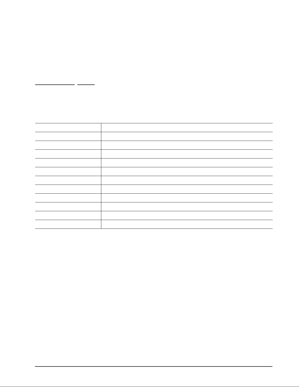
This command con trols the implement ation of var ious features that the dr iv e sup port s. When the drive receives
this command, it sets BSY, checks the contents of the Features register, clears BSY and generates an interrupt. If the value in the register does not represent a feature that the drive supports, the command is aborted.
Power-on default has the read look-ahead and write caching features enabled. The acceptable values for the
Features register are defined as follows:
Table 8: Features register values
02
03
05
55
82
AA
F1
Enable write cache (default).
H
Set transfer mode (based on value in Sector Count register).
H
Sector Count register values:
00
H
01
H
08
H
09
H
0A
H
0B
H
0C
H
20
H
21
H
22
H
40
H
41
H
42
H
43
H
44
H
45
H
Enable advanced power management
H
Disable read look-ahead (read cache) feature.
H
Disable write cache.
H
Enable read look-ahead (read cache) feature (default).
H
Report full capacity available
H
Set PIO mode to default (PIO mode 2).
Set PIO mode to default and disable IORDY (PIO mode 2).
PIO mode 0
PIO mode 1
PIO mode 2
PIO mode 3
PIO mode 4 (default)
Multiword DMA mode 0
Multiword DMA mode 1
Multiword DMA mode 2
Ultra DMA mode 0
Ultra DMA mode 1
Ultra DMA mode 2
Ultra DMA mode 3
Ultra DMA mode 4
Ultra DMA mode 5
Note. At power-on, or after a hardware or software reset, the default values of the features are as indi-
cated above.
Page 33
Momentus 5400.1 Product Manual, Rev. F
27
4.1.4 S.M.A.R.T. co mmands
S.M.A.R.T. provides near-term failure prediction for disc drives. When S.M.A.R.T. is enabled, the drive monitors predetermined drive attributes that are susceptible to degradation over time. If self-monitoring determines
that a failure is likely, S.M.A.R.T. makes a status report available to the host. Not all failures are predictable.
S.M.A.R.T. predictability is limited to the attributes the drive can monitor. For more information on S.M.A.R.T.
commands and implementation, see the Draft ATA-6 Standard.
SeaTools diagnostic software activates a built-in drive self-test (DST S.M.A.R.T. command for D4H) that eliminates unnecessary drive returns. The diagnostic software ships with all new drives and is also available at:
http://seatools.seagate.com.
This drive is ship ped w ith S. M.A.R .T. features disabled. Yo u mu st ha ve a r ecent BIOS or so ft wa re pa ckage that
supports S.M.A.R.T. to enable this feature. The table below shows the S.M.A.R.T. command codes that the
drive uses.
Table 9: Supported S.M.A.R.T. commands
Code in features register S.M.A.R.T. command
D0
D1
D2
D3
D4
D5
D6
D7
D8
D9
DA
H
H
H
H
H
H
H
H
H
H
H
S.M.A.R.T. Read Data
Vendor-specific
S.M.A.R.T. Enable/Disable Attribute Autosave
S.M.A.R.T. Save Attribute Values
S.M.A.R.T. Execute Off-line Immediate (runs DST)
S.M.A.R.T. Read Log Sector
S.M.A.R.T. Write Log Sector
Vendor-specific
S.M.A.R.T. Enable Operations
S.M.A.R.T. Disable Operations
S.M.A.R.T. Return St atus
Note. If an appropriate code is not written to the Features Register, the command is aborted and 0x 04
(abort) is written to the Error register.
Page 34

28
Momentus 5400.1 Product Manual, Rev. F
Page 35
Momentus 5400.1 Product Manual, Rev. F
29
5.0 Compatibility summary
5.1 Installation considerations
Many of today’s mobile com puter s have bee n design ed to make it possible for the end user to rep lace the ha rd
drive. Refer to your system’s user manual for the location of the hard drive compartment and the specific
instructions regarding replacement. Refer to your system manufacturer’s support website for the most up-todate information. Read and follow all instructions regarding the proper steps to be taken when replacing the
system hard drive. Some mobile systems are sealed and require specialized tools to gain access to the hard
drive. Special training or tools may be needed to service some mobile computers. In some cases, opening the
case may void your warranty. Consult your system documentation. Seagate recommends taking your system
to an authorized service technician to replace your hard drive.
System Compatibility
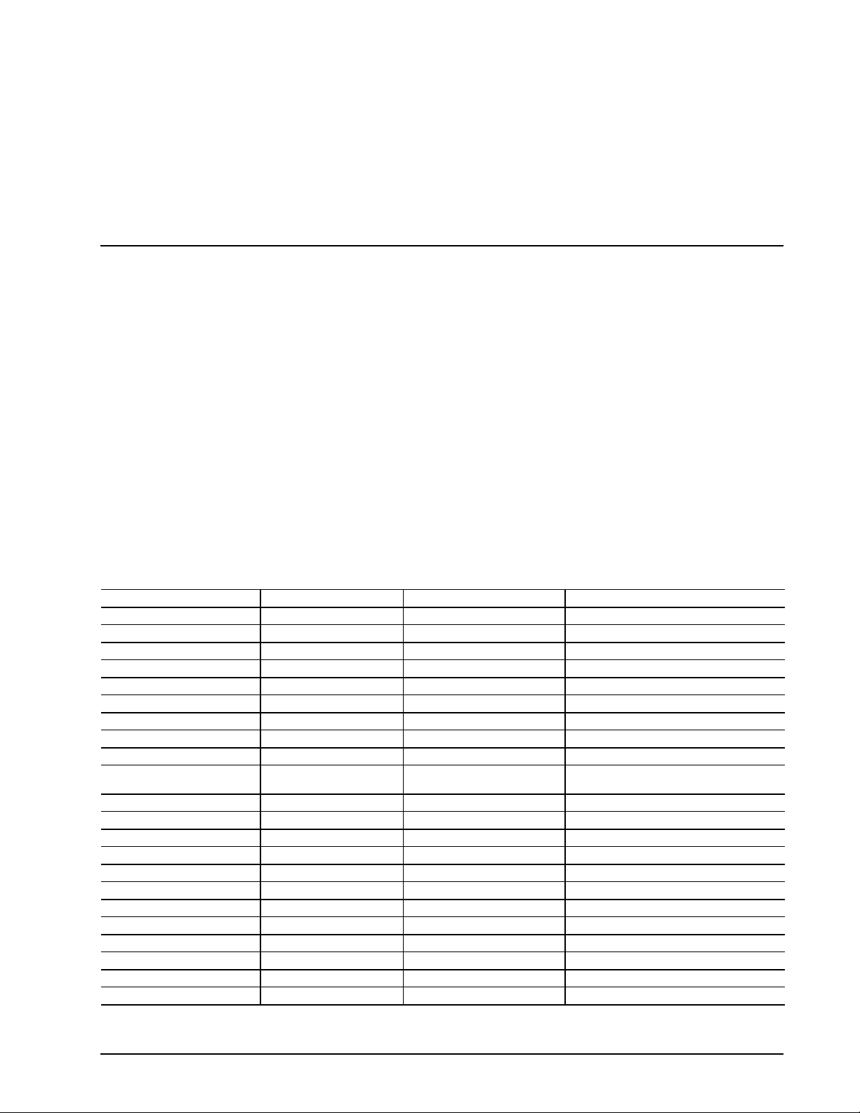
Seagate Product Assurance has test ed Mom entus dr ives in the systems listed below. Testing included multiple
BIOS versions and operating systems. This testing was done to demonstrate compatibility with various hardware and software configurations. Hardware and software combinations, other than those tested, may also be
compatible with this drive.
T a ble 10: T e sted system s
Acer Aspire 1400 Dell Inspiron 8100 Gateway 600Y62 Micron Transport T1000
Acer Travelmate 220 Dell Inspiron 8200 Gateway 600YR Micron Transport V1000
Acer Travelmate 270 Dell Inspiron 8500 Gateway Solo 14550 NEC Japan Versapro VA18S
Acer Travelmate 290 Dell Latitude C400 HP Pavilion ZE5200 NEC Japan Versapro VA20S
Acer Travelmate 420 Dell Latitude C510 HP Pavilion ZE5300 Samsung SENS T10
Acer Travelmate 630 Dell Latitude C510/C610 HP/Compaq EVO N620 Sony VAIO PCG-V505/B
Acer Travelmate 650 Dell Latitude C610 HP/BPC EVO N620 DE266A Sony VAIO PCG-ZIR/P
Acer Travelmate 660 Dell Latitude C640 HP/BPC EVO N800W Taiwan Whitebox ASUSTEK D1
Acer Travelmate 800 Dell Latitude C840 HPD Pavilion ZE1250 Taiwan Whitebox ASUSTEK L3000TP
Acer Travelmate Convertible Dell Latitude D400 IBM Thinkpad T30 Taiwan Whitebox ASUSTEK L4000H
Acer Travelmate Convertible
102T and 104T
Acer Veriton 7200D Dell Latitude X200 Legend L510 and L800 Taiwan Whitebox ECS A907
Apple I BOOK Dell Latitude C844 Legend XPEN T100 Taiwan Whitebox ECS A1080
Apple I BOOK G3 Dell Precision M50 Legend ZHAO Y ANG A820 Taiwan Whitebox LEO AX4R Plus
Compaq EVO 410C Founder A750D Legend ZHAO YANG K71 Taiwan Whitebox LEO M285G
Compaq EVO 610C Founder T5800C Legend ZY SOLEIL D50 Taiwan Whitebox Twinhead 2671
Compaq EVO N620C Fujitsu Seimens Amilio Legend ZHAO YANG V22 Ta iwan Whitebox Twinhead EFIO N1400
Compaq EVO N800C Fujitsu FMV 6120MG3 Legend ZHAO YANG V80 Toshiba Dynabook G7/U24PDDW
Compaq Presario 2135US Fujitsu FMV 7000NA3 LG IBM Thinkpad Toshiba Dynabook G7/X19PDEW
Dell Inspiron 2600 Fujitsu FMV NB18C LG IBM XNOTE Toshiba Portese 3501 Series
Dell Inspiron 2650 Gateway 400SD4 Medion FID Toshiba Techra
Dell Inspiron 4100 Gateway 450R06 Medion FID 2040 Trigem S7 7570
Dell Inspiron 4150 Gateway 450SX4 Micron Transport GX3 Trigem V7 7600
Dell Latitude D600 IBM Thinkpad T40 Taiwan Whitebox ASUSTEK M2000E
Page 36
30
Momentus 5400.1 Product Manual, Rev. F
5.2 BIOS versions tested
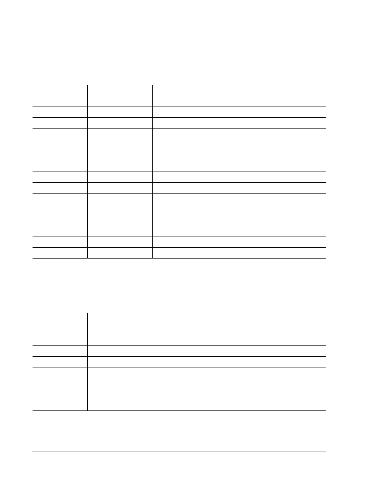
The following list indicates the types of BIOS Seagate tested during the compatibility testing process. The list
highlights the major BIOS manufacturers. Individual systems contain variations of these BIOS versions and
were tested with regard to their implementation in the individual systems.
Table 11: Tested BIOS versions
Vendor Version Version /Release
ACER R01-A013 V3.3
ACPI Ver. 1.20
AMI Various
Apple Various 4.36F3
Apple Various 4.5.4 F1
Award Various
Compaq Various 68xxx
Dell Phoenix Various
IBM Various 1.03
Insyde SCU 1.1
Medion Various 1.17
Mobile Pro V1.04 EC1.01M 4.00.01
Phoenix BIOS Various
Toshiba 1.2
Xpen X42
5.3 Operating system versions tested
This list indicates the types of Operating Systems Seagate tested during the compatibility testing process and
highlights the major OS manufacturers. Several variations of the major operating systems have been tested.
Table 12: Operating systems tested
Manufacturer Version/Release
Apple MacOS 9.22
Apple MacOS X 10.2.3
Microsoft MSDOS 6.22
Microsoft Windows 98, 98SE, ME (multiple languages)
Microsoft Windows 2000, 2000-Pro (+SP 1 thru 4) (multiple languages)
Microsoft Windows NT 4.0 (+SP 6 and 6a) (+Japanese)
Microsoft Windows XP, XP Pro, XP Home (+SP1) (multiple languages)
Redhat Linux 8.0/9.0
Page 37
Momentus 5400.1 Product Manual, Rev. F
31
5.4 Compatibility test configurations
The Momentus drives have been tested to demonstrate compliance with ATA/ATAPI-6 in both the master drive
and slave driv e po sitions. T hese test s were preformed to ensure the function ality to ATA/ATAPI-6 speci fications
and the compatibility of Seagate Momentus drives with other ATA/ATAPI-6 compliant peripherals.
5.5 Software utilities
The following is a brief overview of a some of the Seagate utilities used during the Seagate competitive analysis process.
The Seagate Sea Tools application is an exclusi ve d isc driv e diagn ostic sof tw ar e de signed to tr oublesh oot most
hard drive issues. Desktop edition works with most ATA, SATA, or SCSI drives in desktop systems and has a
98 percent accuracy rate.
The Seagate DiscWizard™ application simplifies the installation of disc drives. This software also overcomes
many system BIOS and operatin g system limi ta tions tha t can co mplicate the inst allatio n of high er-cap acity ATA
(IDE) interface drives.
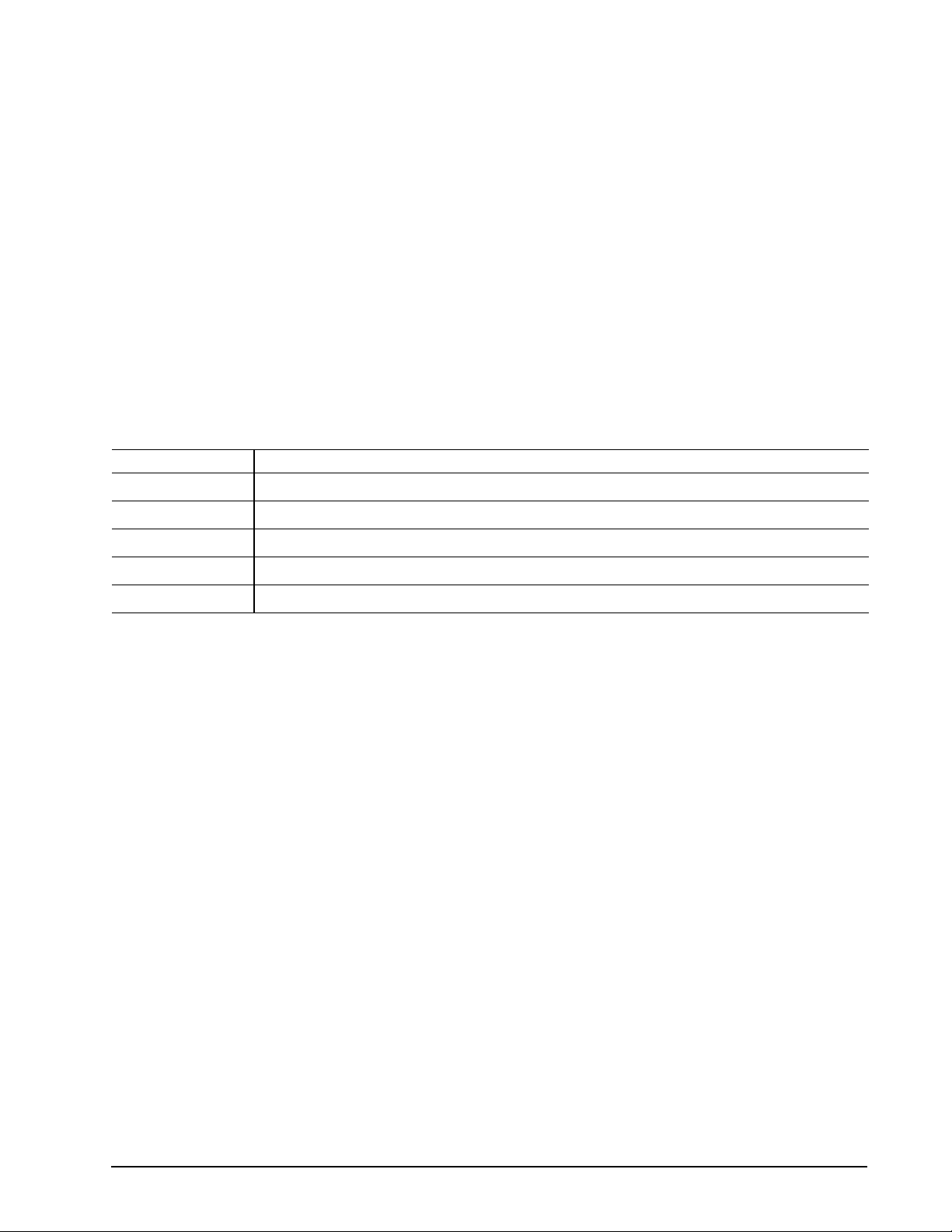
This is a list of some of the third party utilities used in the testing process.
Vendor Application
AMI Diagnostic
Apple Macbench
Intel PCI-EXE
Microsoft Winbench99
Symantec Norton Utilities
5.6 Other certi fi c ation
Microsoft software compatibility.
Page 38

32
Momentus 5400.1 Product Manual, Rev. F
Page 39

Momentus 5400.1 Product Manual, Rev. F
33
6.0 Seagate Technology support services
Internet
For information regarding Seagate products and services, visit www.seagate.com. Worldwide support is
available 24 hours daily by email for your questions.
Presales Support:
T e chn i cal Supp or t:
Warranty Support:
http://www.seagate.com/support/service/index.html
mySeagate
my.seagate.com is the industry's first Web portal designed specifically for OEMs and distributors. It provides
self-service access to critical applications, personalized content and the tools that allow our partners to
manage their Seagate account functions. Submit pricing requests, orders and returns through a single,
password-protected Web interface-anytime, anywhere in the world.
spp.seagate.com
spp.seagate.com supports Seagate resellers with product information, program benefits and sales tools. You
may register for customiz e d communi cation s that ar e not ava ila ble on the web. The s e communi catio ns cont ai n
product launch, EOL, pricing, promotions and other channel-related information. To learn more about the
benefits or to register, go to spp.seagate.com, any time, from anywhere in the world.
Seagate Service Centers
Presales Support
Our Presales Support staff can help you determine which Seagate products are best suited for your specific
application or computer system, as well as product availability and compatibility.
Technical Support
Seagate technical support is available to assist you online at support.seagate.com or through one of our call
centers. Have your system configuration information and your “ST” model number available.
SeaTDD™ (+1-405-324-3655) is a telecommunications device for the deaf (TDD). You can send questions or
comments 24 hours daily and exchange messages with a technical support specialist during normal business
hours for the call center in your region.
Page 40

34
Momentus 5400.1 Product Manual, Rev. F
Customer Service Operations
Warranty Service
Seagate offer s worldwi de custom er supp ort for Seagate pro duct s . Seagate distr i butors, OEM s and other direct
customers should contact their Seagate Customer Service Operations (CSO) representative for warrantyrelated issues. Resellers or end users of drive products should contact their place of purchase or Seagate
warranty service for assistance. Have your serial number and model or part number available.
Data Recove ry Services
Seagate offers data recovery services for all formats and all brands of storage media. Our data recovery
services labs are currently located throughout the world. . Additional information, including an online request
form and data loss prevention resources, is available at http://services.seagate.com/index.aspx
Authorized Service Centers
Seagate Service Centers are available on a global basis for the return of defective products. Contact your
customer support representative for the location nearest you.
USA/Canada/Latin America support services
For an extensive list of telephone numbers to technical support, presales and warranty service in USA/
Canada/Latin America, including business hours, go to the "Contact Us" page on www.seagate.com.
Global Customer Support
Presales, Technical, and Warranty Support
Call Center Toll-free Direct dial
USA, Canada,
and Mexico 1-800-SEAGATE +1-405-324-4700
Data Recovery Services
Call Center Toll-free Direct dial FAX
USA, Canada, 1-800-475-01435 +1-905-474-2162 1-800-475-0158
and Mexico +1-905-474-2459
Europe, the Middle East and Africa Support Services
For an extensive list of telephone numbers to technical support, presales and warranty service in Europe, the
Middle East and Africa, go to the "Contact Us" page on www.seagate.com.
Asia/Pacific Support Services
For an extensive list of telephone numbers to technical support, presales and warranty service in Asia/Pacific,
go to the "Contact Us" page on www.seagate.com
Page 41

Momentus 5400.1 Product Manual, Rev. F
35
Index
Numerics
3D Defense System 1
A
acoustics 13
Active mode 10
agency certification (regulatory) 14
altitude 11
ambient conditions 3
ambient temperature 7, 11
areal density 6
ATA interface 19
ATA-standard commands 20
Australian C-Tick 15
autodetection 1
average seek time 7
B
BIOS manufacturers 30
BPI 6
buffer 1, 6
burst 1
C
cable select 1
cable-select option 18
cache 1, 6
case temperature 11
CE mark 14
certification 14
Check Power Mode 21
commands 20
compatibility 29
compatibility summary 29
compatibility test configurations 31
compliance 14
conducted noise 9
conducted RF immunity 13
configuring the drive 17
connector pins 19
CSA C22.2 (950) 14
CSEL 18
C-Tick 15
current profile 9
cycles 14
D
Data Defense 1
data-transfer rates 1
DC power 8
demonstrate complian ce 31
density 6
Diagnostic Defense 1
diagnostic software 1, 27
discs 5
dissipation 8
Download Microcode 20
Drive Defense 1
drive diagnostics 7
drive monitoring 1
drive self-test 1, 27
DST 27
E
electrical fast transient 13
electromagnetic compatibility 14
Electromagnetic Compatibility Directive 14
electromagnetic immunity 13
electrostatic discharge 13
EMC compliance 14
EN 60950 14
enclosures 15
environmental specification s 11
error-correction algorithms 1
errors 14
European Union 14
Execute Device Diagnostics 20
F
failure prediction 27
FCC verification 15
Features register 26
Flush Cache 20
Flush Cache Extended 20
formatted capacity 5
frequency 13
G
guaranteed sectors 5
H
handling 17
heads 1, 5
height 6
humidity 11
I
I/O data-transfer rate 6
Identify Device 20
Identify Device command 23
Idle 8, 21
Idle and Standby timers 10
Idle Immediate 21
Page 42

36
Momentus 5400.1 Product Manual, Rev. F
Idle mode 10
Idle mode power 8
IEC950 14
Information Technology Equipment 14
Initialize Device Parameters 20
interface 6, 19
interface signals 19
interference 15
interleave 6
internal data-transfer rate OD 6
ISO document 7779 13
J
jumper settings 17
K
Korean RRL 15
L
LBA mode 5
length 6
Load/Unload 14
logical geometry 5
M
master/slave 1
Master/slave configuration 17
maximum temperature 11
Mean time between failures (MTBF) 14
modes 19
monitoring 1
mounting the drive 17, 18
N
noise 9
nominal power 3
nonoperating shock 12
nonoperating vibration 12
nonrecoverable read errors 14
pins 19
PIO 19
power consumption 8
power dissipation 8
power management 10
power on/off cycles 14
power specifications 8
power-management commands 21
power-management modes 10
Power-on to Ready 7
precautions 18
programmable power management 10
R
radiated RF immunity 13
radio and television interference 15
radio frequency (RF) 13
random track location 8
Read Buffer 20
Read DMA 20
Read DMA Extended 20
read errors 14
Read Multiple 1, 20
Read Multiple Extended 20
Read Native Max Address 20
Read Native Max Address Extended 20
Read Sectors 20
Read Sectors Extended 20
Read Verify Sectors 20
Read Verify Sectors Extended 20
read/write heads 5
read/write power and current 8
recording and interface technology 6
recording density 6
recording heads 1
recording method 6
register 26
relative humidity 11
reliability 14
resistance 9
RF 13
O
operating 8
operating power and current 8
operating shock 12
operating system 29
operating vibration 12
OS manufacturers 30
other certification 31
P
physical characteristics 6
physical organization 5
S
S.M.A.R.T. 21
S.M.A.R.T. commands 27
S.M.A.R.T. drive monitoring 1
safety certification 14
screws 18
SeaTools 1, 27
sectors 5
security commands 21
Security Disable Password 22
Security Erase Prepare 21
Security Erase Unit 21
Page 43

Momentus 5400.1 Product Manual, Rev. F
37
Security Freeze Lock 22
Security Set Password 21
Security Unlock 21
Seek 21
seek mode 8
seek time 7
Seeking 8
Service Life 14
servo electronics 8
Set Features 21
Set Features command 26
Set Max 21
Set Multiple Mode 21
shock 12
signals 19
single-track seeks 7
Sleep 8, 21
Sleep mode 10
software utilities 31
sound 13
specifications 3
spindle speed 6
Spinup 8
spinup power 8
Standby 8, 21
Standby Immediate 21
Standby mode 8, 10
Standby to Ready 7
static-discharge precautions 17
subassembly 15
support services 33
surge immunity 13
W
Warranty 14
weight 6
wet bulb temperature 11
width 6
Write Buffer 21
Write DMA 21
Write DMA Extended 21
Write Multiple 1, 21
Write Multiple Extended 21
Write Sectors 21
Write Sectors Extended 21
T
technical support services 33
temperature 11
temperature gradient 11
third party utilities 31
time to ready 7
timers 10
TMR 1
track density 6
track-to-track seek time 7
TUV North America 14
U
UL 1950 14
V
vibration 12
voltage 9
voltage dips, interrupts 13
voltage tolerance 9
Page 44

38
Momentus 5400.1 Product Manual, Rev. F
Page 45

Page 46

Seagate Technology LLC
920 Disc Drive, Scotts Valley, California 95066-4544, USA
Publication Number: 100271718, Rev. F, Printed in USA
 Loading...