

Seagate ST425 Service Manual
'$I;-~fS:L~.
-'!w""'t"
'~,~"r):;ty;
'.- ..
Manhattan House
Bridge Road
Maidenhead
Berkshire SL6 8DB
Telephone:
Maidenhead
(0628) 75851
Telex:
847898 MANSKY
Facsimile:
(0628) 782812
•
ST425 WINCHESTER DISC DRIVE
SERVICE MANUAL
June 28, 1984
•
Manhatt.n ~
Bridge Road
Maidenhead
BerkshireSL6 808
- J
Seagate. 920 Disc Drive. Scotts Valley,CA95066 • (408)438-6550
•
TABLE OF CONTENTS
•
SECTION
l.e
INTRODUCTION ••
1.1 Specification Summary •••••••••••••••••••••••••• 2
1.1.1 Physical Specifications •••••••••••••••••• 2
1.1.2 Reliability Specifications ••••••••••••••• 3
1.1.3 Performance Specifications ••••••••••••••• 4
1.1.4 Functional Specifications •••••••••••••••• 4
2.e THEORY OF OPERATIONS ••••••••••••••••••••••••••••••• 5
2.1 General
2.1.1 Recording Format ••
2.1.2 Track
2.1.3 Read/Write Heads •.••••••••••••••••••••••• 8
2 •1 • 4 DiBe s ••••••••••..••••••••••••••••••••••••• 8
..............
Interface Description •
For mat... 0 ••••••••••••••••••••••••• 7
·.~ .
.............
PAGE
•1
••5-6
•7· .
2.1.5 Air Filtration System •••••••••••••••••••• 8
2.2 Mechanical Theory •.••••••••••••••.••••••••••••• 9
2.2.1 Track 0 Sensor .....•.•...•..........•••.. 9
2.2.2 Index Sensor ••...•..•..••••.....•..•..... 9
2.2.3 Ground Spring •••••
2.3 Electrical Theory ••••••••••••••••••••••
2.3.1 Main Control PC Board 2e321-eel •
2.3.2 Microprocessor Operation ••••••••••••• 11-12
2.3.3 Drive Select •••••••••••••••••••••••••••• 13
2.3.4 Read Operation ••••
2.3.5 Write Operation •••
· .• • •9
•le-18
.... le
· .
· .
•14-15
•16-17
I
2.3.6 Fault Detection •••••••••••••••••
2.4 Test Point Data - PC Board 20321-001 •••••.• 19-21
..... 18
2.5 Schematics
3.0 FIELD SERVICE AND ADJUSTMENTS •
3.1 Removals and Adjustments •••••••••••••••••••••• 26
3.1.1 Main Control PCB ••••••••••.•.••••••••••• 26
Index Sensor •••3.1.2
3.1.3
3.1.4
3.1.5
3.1.6
3.1.7 Track
ILLUSTRATED PARTS CATALOG - INDEX.
4.0
Interface Connectors ••
4.1
4.2
Exploded View •••.••••
Ground Spring ••
Front
Front Cover LED •••
Frame ...•.••••••
- Index •••••••••
· .
· .
Cover ••••••
o
Sensor •••
.....................
· .
..............
................•25-32
......................
.....................
.....................
•••••22
.26
•27
•27
•27
•28
•28
•• 29
••• 30
••• 31
4.3
Component Locations ••••••••••••••
4.4 Parts List - PC Board 20321-001 •••••••••••• 33-34
5.0 FIELD SALES OFFICES •.••••••••••••••••••••••••••••• 35
..........
•••32
II
J
ILLUSTRATIONS
FIGURE PAGE
1.0 Test Point Layout - PC Board 20321-001 •••••••••••• 20
2.0 Test Point Timing - PC Board 20321-001 •••••••••••• 21
3.0 Interface Connectors •••••••••••••••••••••••••••••• 30
4.~ Exploded View ......•..............•..•.•........•. 31
5.0 Component Locations PC Board 20321-001 •••••••••••• 34
III
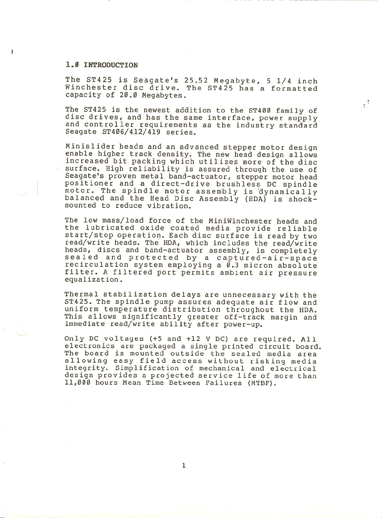
1.8 INTRODUCTION
The ST425 is Seagate's 25.52 Megabyte, 5 1/4 inch
Winchester disc drive. The ST425 has a formatted
capacity of 20.0 Megabytes.
The ST425 is the newest addition to the ST400 family of
disc drives, and has the same interface, power supply
and controller requirements as the industry standard
Seagate ST406/412/419 series.
Minislider heads and an advanced stepper motor design
enable higher track density. The new head design allows
increased bit packing which utilizes more of the disc
surface. High reliability is assured through the use of
Seagate's proven metal band-actuator, stepper motor head
positioner and a direct-drive brushless DC spindle
motor. The spindle motor assembly is aynamically
balanced and the Head Disc Assembly (HDA) is shock-
mounted to reduce vibration.
The low mass/load force of the MiniWinchester heads and
the lubricated oxide coated media provide reliable
start/stop operation. Each disc surface is read by two
read/write heads. The HDA, which includes the read/write
heads, discs and band-actuator assembly, is completely
sealed and protected by a captured-air-space
recirculation system employing a 0.3 micron absolute
filter. A filtered port permits ambient air pressure
equalization.
Thermal stabilization delays are unnecessary with the
ST425. The spindle pump assures adequate air flow and
uniform temperature distribution throughout the HDA.
This allows significantly greater off-track margin and
immediate read/write ability after power-up.
Only DC voltages (+5 and +12 V DC) are required. All
electronics are packaged a single printed circuit board.
The board is mounted outside the sealed media area
allowing easy field access without risking media
integrity. Simplification of mechanical and electrical
design provides a projected service life of more than
11,000 hours Mean Time Between Failures (MTBF).
1

1.1 SPECIFICATION SUMMARY
1.1.1 Physical Specifications
Environmental Limits
Ambient Temperature Limits
Operating:
Non-Operating:
Maximum Temperature Gradient
Operating: 18oF/hour (l~oC/hour)
Non-Operating: Below Condensation
-4eo to 14~oF (-4eo to 6eoC)
•
5~o to 1130F (l~O to 450C)
Relative Humidity:
Maximum Wet Bulb:
Maximum Elevation
Operating:
Non-Operating:
Maximum Shock Without Incurring Physical Damage
[11 msec shock pulse, half sine wave]
Operating:
Longitudinal:
Lateral:
Vertical:
Non-Operating:
No mechanical damage
specified limits.
Maximum Vibration
Operating:
Frequency
2--22 Hz
22-5ee Hz
5~e--22 Hz
22---2 Hz
Without Incurring Soft Errors:
8 to 8e% non-condensing
78.8oF (260C)
-l,~ee feet to le,e~e feet
-l,~~~ feet to 3~,~~0 feet
GiS
3
5 GiS
7 GiS
35 GiS
will occur within the above
.~10"
~.25
0.25
.01~"
double amplitude
G (peak)
G (peak)
double amplitude
•
Maximum Vibration Without
Non-operating:
Frequency
2--22 Hz
22-5~~ Hz
5~~--22 Hz
22--2 Hz
DC Power Requirements
+12 Volts +5%
+5 Volts ±5
Maximum Ripple:
Incurring Physical Damage.
.~4~"
l.~
1.0
.e40"
1.6 A Typ., 3.5 A (at power-on)
1.1 A Typ., 1.7 A (Max.)
5e mV peak to peak (12 V, 5 V)
2
double amplitude
G (peak)
G (peak)
double amplitude
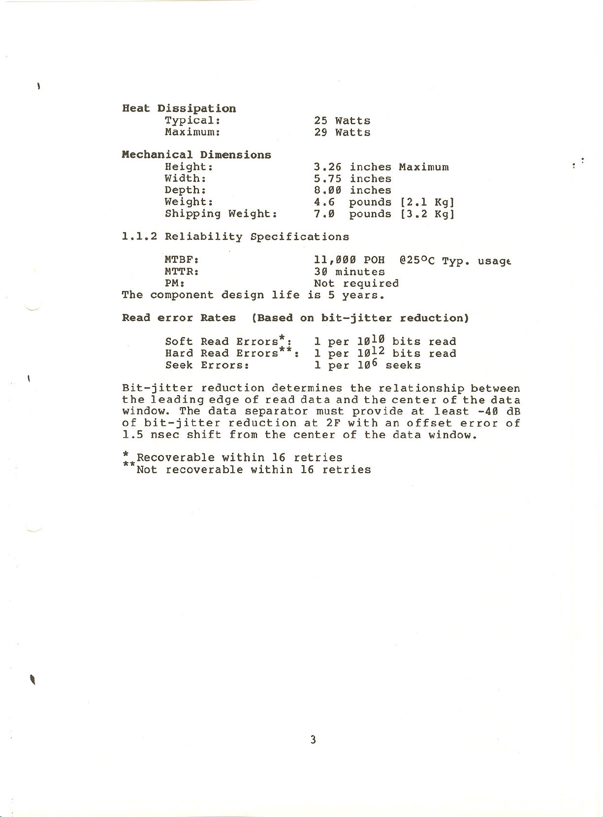
Heat Dissipation
Typical:
Maximum:
Mechanical Dimensions
Height:
Width:
Depth:
Weight:
Shipping Weight:
1.1.2 Reliability Specifications
25 Watts
29 Watts
3.26
5.75
8.00
4.6
7.0
inches
inches
inches
pounds
pounds
Maximum
[2.1 Kg]
[3.2 Kg]
MTBF:
MTTR:
PM:
The component design life
Read error Rates (Based on bit-jitter reduction)
Soft Read Errors :
Hard Read Errors :
Seek Errors:
Bit-jitter reduction determines the relationship between
the leading edge of read data and the center of the data
window. The data separator must provide at least -40 dB
of bit-jitter reduction at 2F with an offset error of
1.5 nsec shift from the center of the data window.
:*Recoverable within 16 retries
Not recoverable within 16 retries
~/
*
**
11,000 POH
30 minutes
Not required
is 5 years.
1 per 1010 bits read
1 per 1012 bits read
1 per 106 seeks
@250C Typ. usagt
\
3

1.1.3 Performance Specifications
CAPACITY
Per Drive:
Per Surface:
Per Track:
Access Time:
Seek Times Including Settling
Single Track: 19.67 msec
Buffered Seek (from last Step pulse to SEEK COMPLETE)
Average Seek: 65 msec
Full Seek: 140 msec
Transfer Rate:
Average Latency:
1.1.4 Functional Specifications
Rotational Speed:
Recording Density:
Flux Density:
Track Density:
Cylinders:
Tracks:
Read/Write Heads:
Discs:
FORMATTED
20.0 MB
5.0 MB
8,192 Bytes
5.0 MBits/sec
8.33 msec
3,600 RPM ±l%
10,568 Bits per inch (Maximum)
10,568 Flux changes per inch (Maximum)
550 Tracks per inch
306
2,448
8
2
UNFORMATTED
25.52 MB
6.38 MB
10,416 Bytes
4
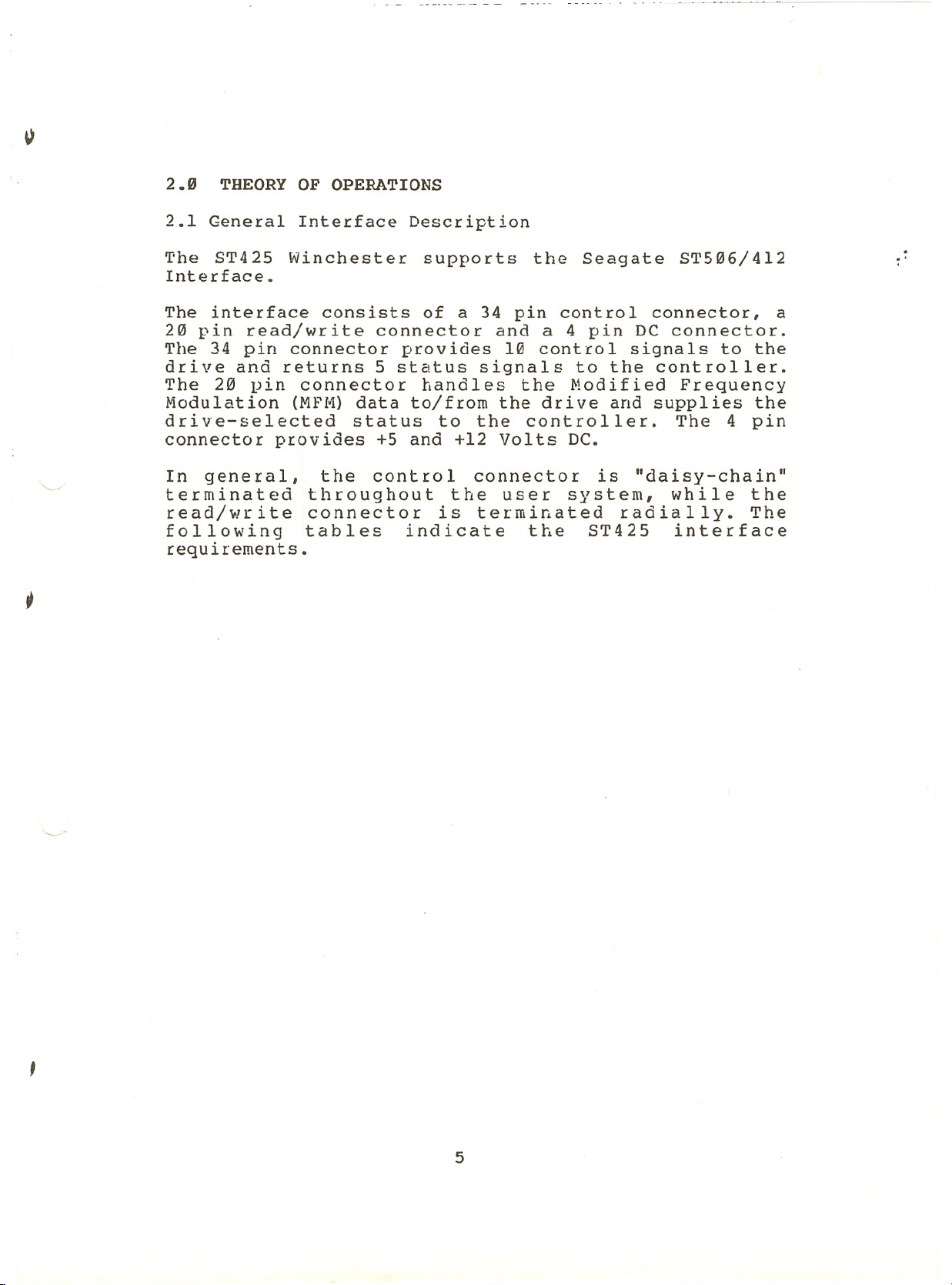
2.0 THEORY OF OPERATIONS
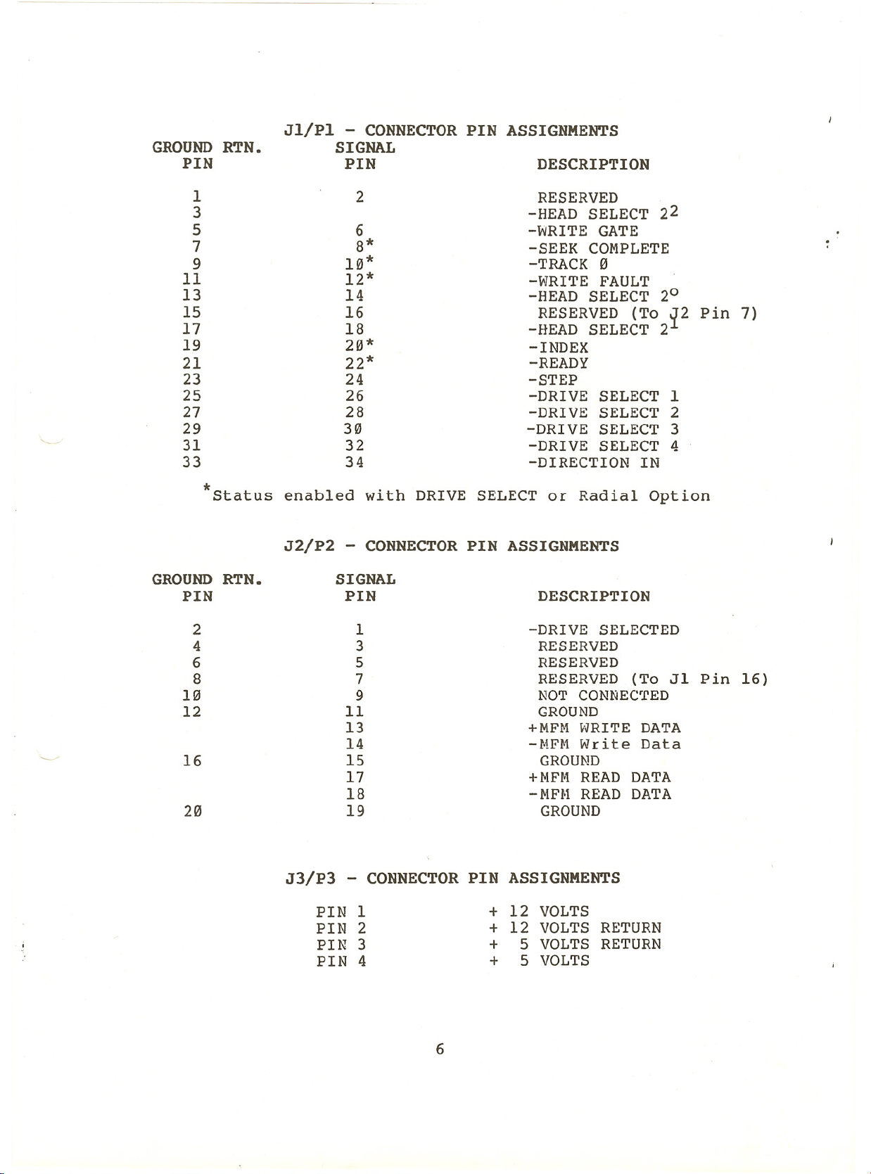
2.1 General Interface Description
The ST425 Winchester supports the Seagate ST506/412
Interface.
The interface consists of a 34 pin control connector, a
20 pin read/write connector and a 4 pin DC connector.
The 34 pin connector provides 10 control signals to the
drive and returns 5 status signals to the controller.
The 20 pin connector handles the Modified Frequency
Modulation (MFM) data to/from the drive and supplies the
drive-selected status to the controller. The 4 pin
connector provides +5 and +12 Volts DC.
In general, the control connector is "daisy-chain"
terminated throughout the user system, while the
read/write connector is terminated radially. The
following tables indicate the ST425 interface
requir'ements.
..
5
PIN
GROUND RTN.
24
28
-DRIVE SELECT 3
32
34
PINDESCRIPTION
2
18
8*
10*
-STEP
26-DRIVE SELECT 1
-DRIVE SELECT 2
30
22*
-DIRECTION IN
16
-HEAD SELECT 2
20*
SIGNAL
RESERVED
6-WRITE GATE
14
-DRIVE SELECT 4
12*
-READY
-INDEX
-TRACK "
Jl/Pl - CONNECTOR PIN ASSIGNMENTS
-HEAD SELECT
-SEEK COMPLETE
-~lRITE FAULT
RESERVED (To ~2 Pin 7)
-HEAD SELECT 22
20
*Status enabled with DRIVE SELECT or Radial Option
PIN
J2/P2 - CONNECTOR PIN ASSIGNMENTS
5
11
PIN
3 RESERVED
RESERVED
7
9NOT CONNEC£ED
GROUND
+MFH HRITE DATA
-HFH Write Data
15 GROUND
+MFr-lREAD DATA
-fvlFHREAD DATA
GROUND RTN. SIGNAL
19 GROUND
DESCRIPTION
1
-DRIVE SELECTED
RESERVED (To J1 Pin 16)
J3/P3 - CONNECTOR PIN ASSIGNMENTS
PIN 1
PIN 2
PIN 3
PIN 4
+ 12 VOLTS
+ 12 VOLTS RETURN
+ 5 VOLTS RETURN
+ 5 VOLTS
6
I P
2.1.1 Recording Format
The ST425 uses Modified Frequency Modulation (MFM) as
the encoding method to record data. This double-density
encoding scheme increases disc capacity by replacing
clock bits with data bits. Clock bits are written only
when data bits are not present in both the preceding and
current bit cell. Clock bits are written at the
beginning of the bit cell, while data bits are written
in the midd Ie.
Due to predictable bit-shift phenomena, the ST425
requires pre-compensation of write data on cylinders 128
through 305. This function must be provided by the
controller to ensure data integrity at the specified
error rate. The data pattern determines which bits must
be pre-compensated. The recommended amount of pre-
compensation is 12 nsec for both early and late written
bits. All other data patterns are written on time.
2.1.2 Track Format
The ST425 uses a slightly modified version of the IBN
System-34 double-density format. This format is common
to many industry standard floppy-disc drives.
When formatted, each sector is identified by a unique
identification field, containing cylinder, head and
sector information, address mark and error checking
polynomials. The Seagate format uses Cyclic Redundancy
Checking (CRC) for error correction. This format also
allows for a plus or minus speed variation of
aproximately 3%. The specification for spindle speed
variation is 1% over the specified environmental and
power limits.
7

2.1.3 Read/Write Heads
When operational, the read/write heads fly on an air
bearing created by the rotating disc. There is no
dedicated landing zone. The head and flexure (supporting
arm) are designed for contact start/stop operation •
The Winchester heads are loaded toward the disc surface
at 9.5 ~l grams. This is a typical value to allow the
required stability in all operating conditions. A
typical flying height measured at an inner radius is 15
±2 microinches. At an outer radius the height is 25 ~3
microinches.
The head/flexure assembly incorporates a low mass
design that is resistive to head and/or media damage.
2.1.4 Discs
The ST425 employs two non-removable double-sided 5 1/4
inch discs. These discs are designed using current iron
oxide technology. Disc dimensions are 40mm inside
diameter by l30mm,outside diameter. The thickness of the
magnetic coating is 20 microinches at the ID and
increases linearly to 40 microinches at the ODe
..
I-
/-
..:.
The disc surface is coated with a flourocarbon lubricant
25 to 55 Angstroms in thickness. The lubricant has
sufficient abrasion resistance to withstand a minimum of
10,000 start/stop cycles.
2.1.5 Air Filtration System
The ST425 incorporates a captured-air-space air
filtration system. The 0.3 micron filter maintains Class
100 standards within the sealed Head Disc Assembly (HDA)
and requires no maintenance during the life of the
drive. A filtered port allows ambient pressure
equalization. During normal operation there is no
measurable air flow between the HDA and the outside
environment.
2.2 Mechanical Theory
2.2.1 Track 0 Sensor
The Track 0 optical interrupter provides an output
whenever the Winchester heads are positioned over
Cylinder Zero. This signal is used by the internal drive
control electronics during the power-on/auto-recalibrate
routine. The Track 0 signal is also output to the drive
interface for use by the controller. Note that the
signal at the interface is really Track 0/Phase A. The
8
 Loading...