

Seagate ST423451N,ST423451W,ST423451WD,Elite 23 ST423451N,Elite 23 ST423451W,Elite 23 ST423451WD Product Manual

. . . . . . . . . . . . . . . . . . . . . . . . . . . . . . . . . . . . . . . . . . . . . . . . .
Elite 23 Disc Drive
. . . . . . . . . . . . . . . . . . . . . . . . . . . . . . . . . . . . . . . . . . . . . . . . .
ST423451N/W/WD
. . . . . . . . . . . . . . . . . . . . . . . . . . . . . . . . . . . . . . . . . . . . . . . . .
. . . . . . . . . . . . . . . . . . . . . . . . . . . . . . . . . . . . . . . . . . . . . . . . .
. . . . . . . . . . . . . . . . . . . . . . . . . . . . . . . . . . . . . . . . . . . . . . . . .
Product Manual, Volume 1
. . . . . . . . . . . . . . . . . . . . . . . . . . . . . . . . . . . . . . . . . . . . . . . . .


. . . . . . . . . . . . . . . . . . . . . . . . . . . . . . . . . . . . . . . . . . . . . . . . .
Elite 23 Disc Drive
. . . . . . . . . . . . . . . . . . . . . . . . . . . . . . . . . . . . . . . . . . . . . . . . .
ST423451N/W/WD
. . . . . . . . . . . . . . . . . . . . . . . . . . . . . . . . . . . . . . . . . . . . . . . . .
. . . . . . . . . . . . . . . . . . . . . . . . . . . . . . . . . . . . . . . . . . . . . . . . .
. . . . . . . . . . . . . . . . . . . . . . . . . . . . . . . . . . . . . . . . . . . . . . . . .
Product Manual, Volume 1
. . . . . . . . . . . . . . . . . . . . . . . . . . . . . . . . . . . . . . . . . . . . . . . . .

© 1997 Seagate Technology, Inc. All rights reserved
Publication number: 83329140, Rev. A
August 1997
Seagate , Seagate Technology , and the Seagate logo are registered trademarks of Seagate Technology, Inc. Elite, SeaFAX, SeaFONE, SeaNET, SeaTDD, and SeaBOARD are either trademarks
or registered trademarks of Seagate Technology, I nc. or one of its subsidiaries. All other trademarks or registered trademarks are the property of their respective owners.
No part of this publication may be reproduced in any form without written permission from
Seagate Technology, Inc.
Printed in the United States of America

Revision status summary sheet
This manual is volume 1 of a two-volume document with the SCSI interface information in the volume 2
SCSI Interface Product Manual
, part number 77738479.
If you need SCSI interface information, order the volume 2
SCSI Interface Product Manual
, part number
77738479.
Revision Date Writer/Engineer Sheets Affected
A 08/25/97 D. Ashby/B. Rathe All


Elite 23 Product Manual, Rev. A v
Contents
1.0 Scope . . . . . . . . . . . . . . . . . . . . . . . . . . . . . . . . . . . . . . . . . . . . . . . . . . . . . . . . . . . . . . . . . . . . . . . . . . 1
2.0 Applicable standards and reference documentation. . . . . . . . . . . . . . . . . . . . . . . . . . . . . . . . . . . . 3
2.1 Standards. . . . . . . . . . . . . . . . . . . . . . . . . . . . . . . . . . . . . . . . . . . . . . . . . . . . . . . . . . . . . . . . . 3
2.1.1 Electromagnetic compatibility . . . . . . . . . . . . . . . . . . . . . . . . . . . . . . . . . . . . . . . . . . 3
2.2 Electromagnetic com pliance . . . . . . . . . . . . . . . . . . . . . . . . . . . . . . . . . . . . . . . . . . . . . . . . . . 3
2.3 Reference d ocuments . . . . . . . . . . . . . . . . . . . . . . . . . . . . . . . . . . . . . . . . . . . . . . . . . . . . . . . 4
3.0 General description. . . . . . . . . . . . . . . . . . . . . . . . . . . . . . . . . . . . . . . . . . . . . . . . . . . . . . . . . . . . . . . 5
3.1 Standard features. . . . . . . . . . . . . . . . . . . . . . . . . . . . . . . . . . . . . . . . . . . . . . . . . . . . . . . . . . . 6
3.2 Media characteristics . . . . . . . . . . . . . . . . . . . . . . . . . . . . . . . . . . . . . . . . . . . . . . . . . . . . . . . . 7
3.3 Performance. . . . . . . . . . . . . . . . . . . . . . . . . . . . . . . . . . . . . . . . . . . . . . . . . . . . . . . . . . . . . . . 7
3.4 Re liability . . . . . . . . . . . . . . . . . . . . . . . . . . . . . . . . . . . . . . . . . . . . . . . . . . . . . . . . . . . . . . . . . 7
3.5 Unformatted and formatted capacit ies . . . . . . . . . . . . . . . . . . . . . . . . . . . . . . . . . . . . . . . . . . . 7
3.6 Programmabl e drive capacity. . . . . . . . . . . . . . . . . . . . . . . . . . . . . . . . . . . . . . . . . . . . . . . . . . 7
3.7 Factory installed accessories. . . . . . . . . . . . . . . . . . . . . . . . . . . . . . . . . . . . . . . . . . . . . . . . . . 8
3.8 Options (factory installed). . . . . . . . . . . . . . . . . . . . . . . . . . . . . . . . . . . . . . . . . . . . . . . . . . . . . 8
3.9 Accessories (user installed) . . . . . . . . . . . . . . . . . . . . . . . . . . . . . . . . . . . . . . . . . . . . . . . . . . . 8
4.0 Performance characteristics . . . . . . . . . . . . . . . . . . . . . . . . . . . . . . . . . . . . . . . . . . . . . . . . . . . . . . . 9
4.1 Internal drive characteristics (transparent to user). . . . . . . . . . . . . . . . . . . . . . . . . . . . . . . . . . 9
4.2 SCSI seek performance characteristics (visible to user) . . . . . . . . . . . . . . . . . . . . . . . . . . . . . 9
4.2.1 Access time . . . . . . . . . . . . . . . . . . . . . . . . . . . . . . . . . . . . . . . . . . . . . . . . . . . . . . . 9
4.2.2 Format command execution time (for ≥ 512-byte sectors). . . . . . . . . . . . . . . . . . . . 9
4.2.3 General performance characteristics . . . . . . . . . . . . . . . . . . . . . . . . . . . . . . . . . . . . 9
4.3 Start/stop time . . . . . . . . . . . . . . . . . . . . . . . . . . . . . . . . . . . . . . . . . . . . . . . . . . . . . . . . . . . . 11
4.4 Prefetch/multi-segmented cache control . . . . . . . . . . . . . . . . . . . . . . . . . . . . . . . . . . . . . . . . 11
4.5 Cache operation. . . . . . . . . . . . . . . . . . . . . . . . . . . . . . . . . . . . . . . . . . . . . . . . . . . . . . . . . . . 11
4.5.1 Caching write data . . . . . . . . . . . . . . . . . . . . . . . . . . . . . . . . . . . . . . . . . . . . . . . . . 12
4.5.2 Prefetch operation . . . . . . . . . . . . . . . . . . . . . . . . . . . . . . . . . . . . . . . . . . . . . . . . . 1 2
5.0 Reliability specifications . . . . . . . . . . . . . . . . . . . . . . . . . . . . . . . . . . . . . . . . . . . . . . . . . . . . . . . . . 15
5.1 Error rates . . . . . . . . . . . . . . . . . . . . . . . . . . . . . . . . . . . . . . . . . . . . . . . . . . . . . . . . . . . . . . . 15
5.1.1 Environmental interference. . . . . . . . . . . . . . . . . . . . . . . . . . . . . . . . . . . . . . . . . . . 15
5.1.2 Read errors. . . . . . . . . . . . . . . . . . . . . . . . . . . . . . . . . . . . . . . . . . . . . . . . . . . . . . . 15
5.1.3 Write errors. . . . . . . . . . . . . . . . . . . . . . . . . . . . . . . . . . . . . . . . . . . . . . . . . . . . . . . 15
5.1.4 Seek errors. . . . . . . . . . . . . . . . . . . . . . . . . . . . . . . . . . . . . . . . . . . . . . . . . . . . . . . 16
5.2 Re liability and serv ic e. . . . . . . . . . . . . . . . . . . . . . . . . . . . . . . . . . . . . . . . . . . . . . . . . . . . . . . 16
5.2.1 Mean time between failure . . . . . . . . . . . . . . . . . . . . . . . . . . . . . . . . . . . . . . . . . . . 16
5.2.2 Preventive maintenance . . . . . . . . . . . . . . . . . . . . . . . . . . . . . . . . . . . . . . . . . . . . . 16
5.2.3 Servi ce life . . . . . . . . . . . . . . . . . . . . . . . . . . . . . . . . . . . . . . . . . . . . . . . . . . . . . . . 16
5.2.4 Service philosophy . . . . . . . . . . . . . . . . . . . . . . . . . . . . . . . . . . . . . . . . . . . . . . . . . 16
5.2.5 Servi ce tools. . . . . . . . . . . . . . . . . . . . . . . . . . . . . . . . . . . . . . . . . . . . . . . . . . . . . . 16
5.2.6 S.M.A.R.T. . . . . . . . . . . . . . . . . . . . . . . . . . . . . . . . . . . . . . . . . . . . . . . . . . . . . . . . 17
5.2.7 Product warranty. . . . . . . . . . . . . . . . . . . . . . . . . . . . . . . . . . . . . . . . . . . . . . . . . . . 18
6.0 Physical/electrical specifications . . . . . . . . . . . . . . . . . . . . . . . . . . . . . . . . . . . . . . . . . . . . . . . . . . 19
6.1 AC power requirements . . . . . . . . . . . . . . . . . . . . . . . . . . . . . . . . . . . . . . . . . . . . . . . . . . . . . 19
6.2 DC power requirements. . . . . . . . . . . . . . . . . . . . . . . . . . . . . . . . . . . . . . . . . . . . . . . . . . . . . 19
6.2.1 Conducted noise immunity . . . . . . . . . . . . . . . . . . . . . . . . . . . . . . . . . . . . . . . . . . . 20
6.2.2 Power sequencing . . . . . . . . . . . . . . . . . . . . . . . . . . . . . . . . . . . . . . . . . . . . . . . . . 20
6.2.3 12 V current profile . . . . . . . . . . . . . . . . . . . . . . . . . . . . . . . . . . . . . . . . . . . . . . . . . 20
6.3 Power dissipation. . . . . . . . . . . . . . . . . . . . . . . . . . . . . . . . . . . . . . . . . . . . . . . . . . . . . . . . . . 21
6.4 Environmental limits. . . . . . . . . . . . . . . . . . . . . . . . . . . . . . . . . . . . . . . . . . . . . . . . . . . . . . . . 21
6.4.1 Temperature. . . . . . . . . . . . . . . . . . . . . . . . . . . . . . . . . . . . . . . . . . . . . . . . . . . . . . 21
6.4.2 Relative humidity . . . . . . . . . . . . . . . . . . . . . . . . . . . . . . . . . . . . . . . . . . . . . . . . . . 23
6.4.3 Effective altitude (sea level) . . . . . . . . . . . . . . . . . . . . . . . . . . . . . . . . . . . . . . . . . . 23
6.4.4 Shock and vibration . . . . . . . . . . . . . . . . . . . . . . . . . . . . . . . . . . . . . . . . . . . . . . . . 23

vi Elite 23 Product Manual, Rev. A
6.4.5 Air cleanliness . . . . . . . . . . . . . . . . . . . . . . . . . . . . . . . . . . . . . . . . . . . . . . . . . . . . .25
6.4.6 Acoustics . . . . . . . . . . . . . . . . . . . . . . . . . . . . . . . . . . . . . . . . . . . . . . . . . . . . . . . . .25
6.4.7 Electromagnetic susceptibility . . . . . . . . . . . . . . . . . . . . . . . . . . . . . . . . . . . . . . . . .25
6.5 Mechanical specifications . . . . . . . . . . . . . . . . . . . . . . . . . . . . . . . . . . . . . . . . . . . . . . . . . . . .25
7.0 Defect and error management . . . . . . . . . . . . . . . . . . . . . . . . . . . . . . . . . . . . . . . . . . . . . . . . . . . . .2 9
7.1 Drive inte rnal defects and errors. . . . . . . . . . . . . . . . . . . . . . . . . . . . . . . . . . . . . . . . . . . . . . .29
7.2 Drive error recovery procedures . . . . . . . . . . . . . . . . . . . . . . . . . . . . . . . . . . . . . . . . . . . . . . .29
8.0 Installation . . . . . . . . . . . . . . . . . . . . . . . . . . . . . . . . . . . . . . . . . . . . . . . . . . . . . . . . . . . . . . . . . . . . .31
8.1 Drive ID/option select header . . . . . . . . . . . . . . . . . . . . . . . . . . . . . . . . . . . . . . . . . . . . . . . . .31
8.1.1 Notes for Figures 8 through 10b . . . . . . . . . . . . . . . . . . . . . . . . . . . . . . . . . . . . . . .36
8.2 Drive orientation . . . . . . . . . . . . . . . . . . . . . . . . . . . . . . . . . . . . . . . . . . . . . . . . . . . . . . . . . . .37
8.3 Cooling . . . . . . . . . . . . . . . . . . . . . . . . . . . . . . . . . . . . . . . . . . . . . . . . . . . . . . . . . . . . . . . . . .37
8.3.1 Air flow. . . . . . . . . . . . . . . . . . . . . . . . . . . . . . . . . . . . . . . . . . . . . . . . . . . . . . . . . . .37
8.4 Drive mounting . . . . . . . . . . . . . . . . . . . . . . . . . . . . . . . . . . . . . . . . . . . . . . . . . . . . . . . . . . . .38
8.5 Grounding . . . . . . . . . . . . . . . . . . . . . . . . . . . . . . . . . . . . . . . . . . . . . . . . . . . . . . . . . . . . . . . .38
9.0 Interface requiremen ts. . . . . . . . . . . . . . . . . . . . . . . . . . . . . . . . . . . . . . . . . . . . . . . . . . . . . . . . . . . .39
9.1 General description . . . . . . . . . . . . . . . . . . . . . . . . . . . . . . . . . . . . . . . . . . . . . . . . . . . . . . . . .39
9.2 SCSI interface messag es supported. . . . . . . . . . . . . . . . . . . . . . . . . . . . . . . . . . . . . . . . . . . .39
9.3 SCSI interface command s supported . . . . . . . . . . . . . . . . . . . . . . . . . . . . . . . . . . . . . . . . . . .40
9.3.1 Inquiry data . . . . . . . . . . . . . . . . . . . . . . . . . . . . . . . . . . . . . . . . . . . . . . . . . . . . . . .43
9.3.2 Mode Sense data. . . . . . . . . . . . . . . . . . . . . . . . . . . . . . . . . . . . . . . . . . . . . . . . . . .43
9.4 SCSI bus conditions and miscellaneous features support ed . . . . . . . . . . . . . . . . . . . . . . . . .47
9.5 Synchronous data transfer . . . . . . . . . . . . . . . . . . . . . . . . . . . . . . . . . . . . . . . . . . . . . . . . . . .48
9.5.1 Synchronous data transfer periods supported. . . . . . . . . . . . . . . . . . . . . . . . . . . . .48
9.5.2 REQ/ACK offset. . . . . . . . . . . . . . . . . . . . . . . . . . . . . . . . . . . . . . . . . . . . . . . . . . . .48
9.6 Physical interface . . . . . . . . . . . . . . . . . . . . . . . . . . . . . . . . . . . . . . . . . . . . . . . . . . . . . . . . . .48
9.6.1 DC cable and connector . . . . . . . . . . . . . . . . . . . . . . . . . . . . . . . . . . . . . . . . . . . . .48
9.6.2 SCSI interface physical description. . . . . . . . . . . . . . . . . . . . . . . . . . . . . . . . . . . . .50
9.6.3 SCSI interface cable requirements . . . . . . . . . . . . . . . . . . . . . . . . . . . . . . . . . . . . .50
9.6.4 Mating connectors . . . . . . . . . . . . . . . . . . . . . . . . . . . . . . . . . . . . . . . . . . . . . . . . . .51
9.7 Electrical description . . . . . . . . . . . . . . . . . . . . . . . . . . . . . . . . . . . . . . . . . . . . . . . . . . . . . . . .58
9.7.1 Single-ended drivers/receivers . . . . . . . . . . . . . . . . . . . . . . . . . . . . . . . . . . . . . . . .58
9.7.2 Differential drivers/receivers . . . . . . . . . . . . . . . . . . . . . . . . . . . . . . . . . . . . . . . . . .59
9.8 Terminator requirements. . . . . . . . . . . . . . . . . . . . . . . . . . . . . . . . . . . . . . . . . . . . . . . . . . . . .61
9.9 Terminator power . . . . . . . . . . . . . . . . . . . . . . . . . . . . . . . . . . . . . . . . . . . . . . . . . . . . . . . . . .61
9.10 Disc drive SCSI timing. . . . . . . . . . . . . . . . . . . . . . . . . . . . . . . . . . . . . . . . . . . . . . . . . . . . . . .62
10.0 Seagate technical support services. . . . . . . . . . . . . . . . . . . . . . . . . . . . . . . . . . . . . . . . . . . . . . . . .65

Elite 23 Product Manual, Rev. A vii
List of Figures
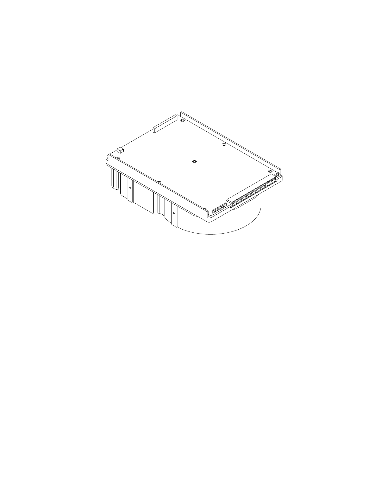
Figure 1. Elite 23 disc drive (ST423451N drive shown) . . . . . . . . . . . . . . . . . . . . . . . . . . . . . . . . . . . . . 1
Figure 2. Elite 23 family drive . . . . . . . . . . . . . . . . . . . . . . . . . . . . . . . . . . . . . . . . . . . . . . . . . . . . . . . . . 6
Figure 3. Typical Elite 23 drive +5 V and +12 V current profile. . . . . . . . . . . . . . . . . . . . . . . . . . . . . . . 20
Figure 4. Location of PCB components listed in Table 3. . . . . . . . . . . . . . . . . . . . . . . . . . . . . . . . . . . . 22
Figure 5. Recommended mounting . . . . . . . . . . . . . . . . . . . . . . . . . . . . . . . . . . . . . . . . . . . . . . . . . . . . 24
Figure 6. Mounting configuration dimensions for “N” models . . . . . . . . . . . . . . . . . . . . . . . . . . . . . . . . 26
Figure 7. Mounting configuration dimensions for “W” and “WD” models. . . . . . . . . . . . . . . . . . . . . . . . 27
Figure 8. ST423451N option select jumper connectors . . . . . . . . . . . . . . . . . . . . . . . . . . . . . . . . . . . . 32
Figure 9a. ST423451W/WD option select jumper connectors . . . . . . . . . . . . . . . . . . . . . . . . . . . . . . . . . 33
Figure 9b. ST423451 “WD” model auxillary remote cable ID select . . . . . . . . . . . . . . . . . . . . . . . . . . . . 34
Figure 10a. J4A connections for Activity, Fault, and Ready LED indicators for all models . . . . . . . . . . . . 35
Figure 10b. J7 auxiliary remote cable connections for Ready and Fault indicators, “WD” model only . . . 35
Figure 11. Suggested air flow . . . . . . . . . . . . . . . . . . . . . . . . . . . . . . . . . . . . . . . . . . . . . . . . . . . . . . . . . 37
Figure 12. Physical interface for “N” model drives. . . . . . . . . . . . . . . . . . . . . . . . . . . . . . . . . . . . . . . . . . 49
Figure 13. Physical interface for “W” and “WD” model drives . . . . . . . . . . . . . . . . . . . . . . . . . . . . . . . . . 49
Figure 14. SCSI daisy-chain interface cabling. . . . . . . . . . . . . . . . . . . . . . . . . . . . . . . . . . . . . . . . . . . . . 52
Figure 15. Non-shielded 50-pin SCSI device connector . . . . . . . . . . . . . . . . . . . . . . . . . . . . . . . . . . . . . 53
Figure 16. Non-shielded 68-pin SCSI device connector . . . . . . . . . . . . . . . . . . . . . . . . . . . . . . . . . . . . . 53
Figure 17. Single-ended transmitters and receivers . . . . . . . . . . . . . . . . . . . . . . . . . . . . . . . . . . . . . . . . 58
Figure 18. Typical differential I/O line transmitter/receiver and terminators . . . . . . . . . . . . . . . . . . . . . . 60

Elite 23 Product Manual, Rev. A 1
1.0 Scope
This manual describes Seagate Tec hnology®, Inc. Elite 23™ disc drives.
Elite 23 drives support the small computer system interface (SCSI) as described in the ANSI SCSI, SCSI-2,
and SCSI-3 (Fast-20) interface specifications to the extent described in this manual. The
SCSI Interface Prod-
uct Manual
(part number 77738479) describes general SCSI interface characteristics of this and other families
of Seagate drives.
From this point on in this product manual the reference to Elite 23 m odels is referred to as “the dri ve” (unless
references to individual models are necessary).
Figure 1. Elite 23 disc drive (ST423 451N drive shown)


Elite 23 Product Manual, Rev. A 3
2.0 Applicable standards and reference documentation
The drive is a system peripheral developed to the highest standards of design and construction. The dr ive
depends on its host equipment to provide adequ ate power and environment to achieve optimum performance
and compliance with applicable in dustry and government regulations. Special attention must be given in the
areas of safety, power distr ibution, shi elding, a udible nois e cont rol, and temperature regulation. Also, the drive
must be securely mounted to guarantee the specified performance characteristics.
2.1 Standards
The Elite 23 family complies with Seagate standards as noted in the appropr iate sections of this manual and
the Seagate
SCSI Interface Product Manual
(volume 2), part number 77738479.
The Elite 23 disc drive is a UL recognized com ponent per UL1950, CSA c ertified to CSA C22.2 No. 950-M89,
and VDE certified to VDE 0805 and EN 60950.
2.1.1 Electromagnetic compatibility
The drive, as delivered, is designed f or s ystem integr ation and installation into a suitable enclosure prior to use.
As such, the drive is supplied as a subassembly and is not subject to Subpart B of Part 15 of the FCC Rules
and Regulations nor the Radio Interference Regulations of the Canadian Department of Communications.
The physical design characteristics of the drive ser ve to m inimize radiation when i nstalled in a n enclosure t hat
provides reasonable shielding. As such, the drive is capable of meeting the Class B limits of the FCC Rules
and Regulations of the Canadian Depar tment of Com munications when proper ly packaged. However, it is the
user’s responsibility to assure that the drive meets the appropriate EMI requirements in their system. Shielded
I/O cables may be required if the enclosure does not provide adequ ate shieldi ng. If the I/O cables are externa l
to the enclosure, shielded cables should be used, with the shields grounded both to the enclosure and to the
host controller.
2.1.1.1 Electromagnetic susceptibility
As a component assembly, the drive is not required to meet any susceptibility performance requirem ents. It is
the responsibility of those integrating the dri ve within their system s to perform thos e tes ts req uired a nd desig n
their system to ensure that equipm ent operating in the same system as the drive or external to the system
does not adversely affect the performance of the drive. See Section 5.1.1 and Table 2, DC power requirements.
2.2 Electromagnetic compliance
Seagate uses an independen t laboratory to confirm compliance to the directives/standard(s) for CE Marking
and C-Tick Marking. The drive was tested in a representative system for typical applications. The selected system represents the most popular characteristics for test platforms. The system configurations include:
• 486, Pentium, and PowerPC microprocessors
• 3.5-inch floppy disc drive
• Keyboard
• Monitor/display
• Printer
• External modem
•Mouse
Although the test system with this Seagate model complies to the directives/standard(s), we cannot guarantee
that all systems will comply. The computer manufacturer or system integrator shall confirm EMC compliance
and provide CE Marking and C-Tick Marking for their product.
Electromagnetic compliance for the European Union
If this model has the CE Marking it complies with the European Union requirements of the Electromagnet ic
Compatibility Directive 89/336/EEC of 03 May 1989 as amended by Directive 92/31/EEC of 28 April 1992 and
Directive 93/68/EEC of 22 July 1993.

4 Elite 23 Product Manual, Rev. A
Australian C-Ti ck
If this model has the C-Tick Marking it complies with the Au stralia/New Zealand Standard AS/NZS3548 1995
and meets the Electromagnetic Compatibility (EMC) Framework requirements of Australia’s Spectrum Management Agency (SMA).
2.3 Reference documents
Elite 23 Installation Guide
Seagate P/N 83329130
SCSI Interface Product Manual
(Volume 2) Seagate P/N 77738479
ANSI small computer system interface (SCSI) document numbers:
X3.131-1994 SCSI-2
X3T10/855D rev . 15a SPI
X3T10/1071D rev. 6 Fast-20 (also called “Ultra SCSI”)
Package Test Specification Seagate P/N 30190-001 (under 100 lb.)
Package Test Specification Seagate P/N 30191-001 (over 100 lb.)
In case of conflict between this document and any referenced document, this document takes precedence.

Elite 23 Product Manual, Rev. A 5
3.0 General description
Elite 23 drives combine magnetoresistive (MR) heads, partial response/maximum likelihood (PRML) read
channel electronics, embedded servo technology, and a SCSI-3 (Fast-20) interface to provide high performance, high capacity data storage for a variety of systems including engineering workstations, network servers, mainframes, and supercomputers.
Fast-20 (also known as Ultra SCSI) is a negotiated transfer rate. This transfer rate will occur only if your host
adapter also supports Fast-20 data transfer rates. This drive also operates at SCSI-1 and SCSI-2 data transfer
rates for backward compatibility with non-Fast-20 capable SCSI host adapters.
Table 1 lists the features that differentiate the various Elite 23 SCSI-3 Fas t-20 (Ultra SCSI) models.
Table 1: Drive model number vs. differentiating features
The drive records and recovers data on 5.25-inch (133.4 mm) non-removeable discs.
The drive suppor ts the Small Computer System Interface (SCSI) as describ ed in the ANSI SCSI-2 interface
specifications to the extent described in this manual (volume 1), which defines the product perform ance characteristics of the Elite 23 family of drives, and the
SCSI Interface Product Manual
(volume 2), par t number
77738479, which describes t he general interface characteristics of this and other families of Seagate SCSI
drives.
The drive’s interface supports multiple initiators, disconnect/reconnect, self-configuring host software, and
automatic features that relieve the host from the necessity of knowing the physical characteristics of the targets
(logical block addressing is used).
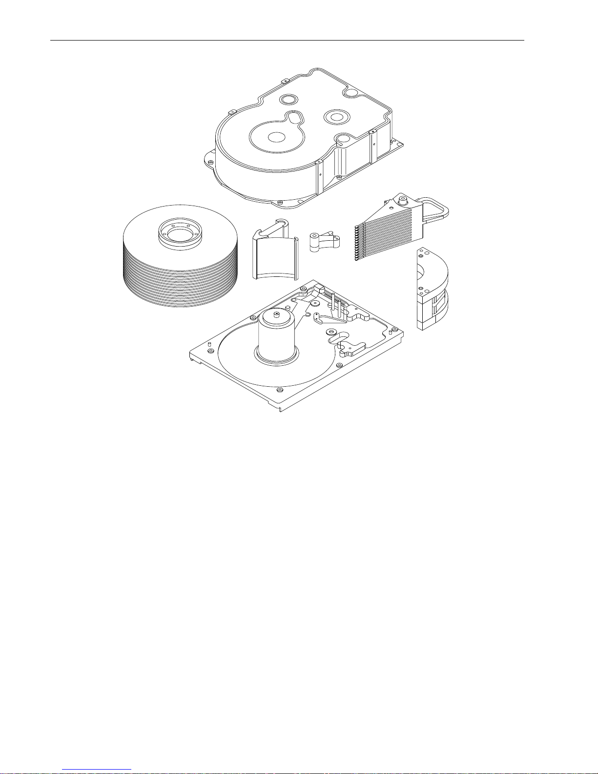
The head and disc assembly (HDA) is sealed at the factory. Air circulates within the HDA through a nonreplaceable filter to maintain a contamination-free HDA environment.
Refer to Figure 2 for an exploded view of the drive. This exploded view is for information only—never disassemble the HDA and do not attempt to service items in the sealed enclosure (heads, med ia, actuator, etc.) as this
requires special facilities. The drive contains no replaceable parts. Opening the HDA voids your warranty.
Elite 23 drives use a dedicated landing zone at the innermost radius of the media to eliminate the possibilit y of
destroying or degrading data by landing in the data zone. The drive automatically goes to the land ing zone
when power is removed.
An automatic shipping lock prevents potential damage to the heads and discs that results from movement during shipping and handling. The shipping lock automatical ly disenga ges when power is appli ed to the drive and
the head load process begins.
Elite 23 drives decode track 0 location data from the servo data embedded on each surface to eliminate
mechanical transducer adjust m ents and re lated r eliability concern s.
A high-performance actuator ass embly with a low-inertia, balanced, pa tented, straight-arm design provides
excellent performance with minimal power dissipation.
Model number I/O circuit type
Number of I/O
connector pins
Number of I/O
data bus bits
ST423451N single-ended 50 8 (fast)
ST423451W single-ended 68 16 (fast/wide)
ST423451WD differential 68 16 (fast/wide)
6 Elite 23 Product Manual, Rev. A
Figure 2. Elite 23 family drive
3.1 Standard features
Elite 23 drives have the following standard features:
• Integrated SCSI controller
• Single-ended or differential SCSI drivers and receivers
• 8-bit and 16-bit I/O data bus models available
• Asynchronous and synchronous data transfer protocols
• Firmware downloadable using a SCSI interface
• Programmable drive capacity
• Selectable sector size from 512 to 4,096 bytes per sector
• Programmable sector reallocation scheme
• Flawed sector reallocation using sector slipping at format time
• Programmable auto write and read reallocation
• Reallocation of defects on command (post format)
• Reed-Solomon error-correction code for header and data fields; can correct up to 64-bit error
• Sealed head and disc assembly (HDA)
• No preventative maintenance or adjustment required
• Dedicated head-landing zone
• Embedded servo data rather than a separate servo data surface
• Self-diagnostics performed when power is applied to the drive
• 1:1 interleave
• Zone bit recording (ZBR)
• Vertical, horizontal, or top-down mounting

Elite 23 Product Manual, Rev. A 7
• Dynamic spindle brake
• Active IC terminators enabled by jumper (“N” and “W” models only)
• 2,000 Kbyte data buffer. See Section 4.5
• SCAM (SCSI Configured Auto Magically) Plug-n-Play Level 1 compliant. SCAM Level 2 is a factory-installed
option.
3.2 Media characteristics
The media used on the drive has a diameter of approximately 5. 25 i nches (134 m m ). The aluminum subs trate
is coated with a thin film magnetic material, overcoated with a proprietary protective lay er f or improved durability and environmental protection.
3.3 Performance
• Supports industry-standard Fast-20 SCSI interface (also called “Ultra SCSI”)
• Programmable multi-segmentable cache buffer
• 5,400 RPM spindle; average latency = 5.55 msec
• Command queuing of up to 64 commands
• Background processing of queue
• Supports start and stop commands (spindle stops spinning)
• Low audible noise for office environment
• Low power consumption
3.4 Reliability
• 800,000 hour MTBF
• LSI circuitry
• Balanced low mass rotary voice coil actuator
• Incorporates industr y -standa rd Self-Monit orin g, Analysis and Reporting Tec hnol ogy (S.M.A.R.T.)
• Incorporates Seek To Im pr ove Reliability alg orithm (ST IR)
• Dithering algorithm
• 5-year warranty
3.5 Unformatted and formatted capacities
Formatted capacity depends on the number of spare reallocation sectors reserved and the number of bytes per
sector. The following table shows standard OEM model capacities:
Notes.
[1] Standard OEM models are formatted to have 512-byte sectors. Sector size selectable at format time.
Users having the necessar y equi pm ent may modi fy the da ta block size before issuing a format c om man d
and obtain different formatted capacities than those listed. User available capacity depends on spare reallocation scheme selected. See Mode Select Command and Format Command in the
SCSI Interface Prod-
uct Manual,
part number 77738479.
[2] The number of data tracks per sparing zone and the number of alternate sectors (LBAs) per sparing zone
can be determined by using the Mode Sense command and reading M ode page 03h.
3.6 Programmable drive capacity
Using the Mode Select command, the drive can change its capacity to something less than maximum. See
Table 5.2.1-13 in the
SCSI Interface Product Manual
, part number 77738479. Refer to the Parameter list block
descriptor number of blocks field. A value of zero in the number of blocks field indicates that the drive shall not
change the capacity it is currently formatted to have. A number in the number of blocks field that is less than
the maximum number of L BAs chan ges the tota l drive capacity to t he value in the block de scriptor num ber of
blocks field. A value greater than the maximum number of LBAs is rounded down to the maximum capacity.
Formatted [1] Unformatted
ST423451 23.2 Gbytes [2] 29.4 Gbytes

8 Elite 23 Product Manual, Rev. A
3.7 Factory installed accessories
The
Elite 2 3 I n stallation Guide
, part num ber 83 329130, is shipped with eac h s tandard OEM dr ive (unless ot herwise specified). A small bag of jumpers are also s hipped with the dri ve. Use these jumpers to configure the
option headers. See Section 8.1.
SCSI terminators can be enabled or disabled on “N” and “W” models.
3.8 Options (factory installed)
All options that a cus t ome r m ay request are incorporated du ring production or packaged at t he m anufacturing
facility before shipping. Some of the options available are:
• The capacities shown in Section 3.5. You can order other capacities by selecting other sparing schemes and
sector sizes.
• Single-unit shipping pack. The drive normally ships in bulk packaging to provide maximum protection against
transit damage. Units shipped in dividually require additional protection as provided by the sin gle-unit shipping pack. Specify this option if you are planning to ship single units to your customers.
• The
Elite 23 Installation Guide
, part number 83329130, is usually in cluded with each standard OE M drive.
Additional copies may be ordered.
• SCAM Level 2 compliance.
3.9 Accessories (user installed)
The following accessories are available.
• Single-unit shipping pack.

Elite 23 Product Manual, Rev. A 9
4.0 Performance characteristics
4.1 Internal drive characteristics (transparent to user)
[1] Rounded off values
4.2 SCSI seek performance characteristics (visible to user)
The values given in Section 4.2.1 apply to all Elite 23 models unless otherwise specified. Refer to Section 9.10
and to the
SCSI Interface Product Manual
(part number 77738479) for additional timing details.
4.2.1 Access time
4.2.2 Format command execution time (for ≥ 512-b yte sectors)
4.2.3 General performance characteristics
Data buffer data transfer rate to/from disc media (one 512-byte sector) variable with zone/cylinder:
SCSI interface data transfer rate (asynchronous) [5]:
Maximum instantaneous (1-byte-wide transfer rate) 5.0 Mbytes/sec [6]
Maximum instantaneous (2-byte-wide transfer rate) 10.0 Mbytes/sec [7]
Synchronous transfer rate for SCSI Fast-20 (Ultra SCSI):
8 bit data bus models 2.5 to 20 Mbytes/sec
16 bit data bus models 5.0 to 40 Mbytes/sec
[] All notes for Sections 4.2 are listed at end of Section 4.2.3.
ST423451
Drive capacity 29.4 Gbyte (unformatted) [1]
Read/write heads 28
Bytes/track 152,908 Bytes (average, unformatted) [1]
Bytes/surface 1,051 Mbytes (unformatted)
Tracks/surface, total 6,876 T racks (user accessible)
Tracks/inch 5,555 TPI
Peak bits/inch 125,360 BPI
Internal data rate 86-124 Mbits/sec (variable with zone)
Disc rotational speed 5,400 ± 0.5% r/min
Average rotational latency 5.55 msec
Including controller overhead
(without discon nect) [1] [4]
Drive level
Read Write
ms
Average Typical [3] 13.2 14.2
Single track Typical [3] 1.3 2.3
Full stroke Typical [3] 28.2 28.2
Maximum (with verify) 6.5 hours
Maximum (no verify) 3.75 hours
Minimum sector interleave 1 to 1
Minimum [4] 86 Mbits/sec
Maximum [4] 124 Mbits/sec

10 Elite 23 Product Manual, Rev. A
Synchronous transfer rate for fast SCSI-2:
8 bit data bus models 1.25 to 10 Mbytes/sec
16 bit data bus models 2.5 to 20 Mbytes/sec
Secto r sizes:
Default 512-byte data blocks
Variable in even-sector sizes 512 to 4,096 bytes per sector
Read/write consecutive sectors on a track Yes
Flaw reallocation performance impact :
For flaws reallocated at format time using spare
sectors per track reallocation scheme negligible
For flaws reallocated after for m at time using spare
sectors per cylinder reallocation scheme 11.1 msec (minimum)
22.2 msec (maximum)
For flaws reallocated after for m at time using spare
tracks per volume reallocation scheme 35 msec (typical)
Overhead time for head switch (512-byte sectors)
in sequential mode 0.8 msec
Overhead time for one track cylinder switch
in sequential mode 1.2 msec (typical)
Aver age rotational latency 5.55 msec
Notes for Sections 4.2.
[1] Execution time is measured from receipt of the last byte of the Command Descriptor Block (CDB) to the
request for a status byte transfer to the initiator (excluding connect/disconnect).
[2] Maximum times are specified over the worst case conditions of temperature, voltage margins and dr ive
orientation. When comparing specified access times, take care to distinguish between typical access
times and maximum access times. Obtain the best comparison by conducting system benchmark tests
under identical conditions. Maximum times do not include error recovery.
[3] Typical access tim es are measured und er nominal con ditions of temperature, voltage, and horizontal or i-
entation as measured on a representative sample of drives.
[4] Assumes no errors and no sector reallocations.
[5] Rate measured from the start of the first sector transfer to or from the host.
[6] Assumes system ability to support the 1-byte-wide transfer rate listed and no cable loss.
[7] Assumes system ability to support the 2-byte-wide transfer rate listed and no cable loss.

Elite 23 Product Manual, Rev. A 11
4.3 Start/stop time
Disabling the Motor Start option causes the drive to become ready within 45 seconds after DC power is applied
at nominal voltage. This means the motor starts as soon as power is applied. If a recoverable error condition is
detected during the star t sequence, the drive will exe cute a recovery procedure and may cause the time to
become ready to exceed 45 seconds. During this time the drive responds to some commands over the SCSI
interface. Stop time is less than 40 seconds from removal of DC power.
Enabling the Motor Start option causes the internal controller to accept the commands listed in the
SCSI Inter-
face Product Manual
(77738479) less than 3 second s after appl ying DC power. After receiving the Motor Start
command, the drive becomes ready for normal operations within 45 seconds (excluding an error recovery procedure). The Motor Start command can also be us ed to co mmand t he drive to stop the spindle in less than 40
seconds (see the Start/Stop com man d information in the
SCSI Interface Product Manual).
There is no power control switch on the drive.
4.4 Prefetch/multi-segme nted cach e control
The drive provides prefetch (read look-ahead) and multi-segmented cache control algorithms that in many
cases can enhance system performance. “Cache” as used herein refers to the drive b uffer storage space when
it is used in “cache” operat ions. To sele ct prefetch and cache features the host sends the Mo de Select command with the proper values in the applicable bytes in Mode Page 08h (see
SCSI Interface Product M anual
).
Prefetch and cache operation are ind ependent features from the standpoint that eac h is enabled and disabled
independently via the Mode Select command. However, in actual operation the prefetch feature overlaps cache
operation somewhat as is noted in Section 4.5.1 and 4.5.2.
All default cache and prefetch Mode parameter values (Mode Page 08h) for standard OEM versions of t his
drive family are given in Table 8.
4.5 Cache op eration
Of the 2,048 Kbytes physical buffer space, approximately 1,442 Kbytes can be used as a cache. The cach e
can be divided into logical segments (M ode Select page 08h, byte 13) from which data is read and to wh ich
data is written.
The drive keeps track of the logical block addresses of the data stored in each segment of the cache. If the
cache is enabled (see RCD bit = 0 in Mode page 08h, byte 2, bit 0 in the
SCSI Interface Product Manual),
data
requested by the host with a read command is retrieved from the cache, if possible, before any disc access is
initiated. If cache operation is not enabled, the buffer (still segmented with required number of segments) is still
used, but only as circular buffer segments during disc medium read operations (disregarding Prefetch operation for the moment). That is, the drive does not check in the buffer segments for the requested read data, but
goes directly to the medium to retrieve it. The retrieved data merely passes through some buffer segment on
the way to the host. On a cache “miss,” all data transfers to the host are in accordance with “buffer-full” ratio
rules. On a cache “hit,” the drive ignores the “buffer-full” ratio rules. See explanations associated with Mode
page 02h (disconnect/reconnect control) in the
SCSI Interface Product Manual
.
The following is a simplified description of a read operation with cache operation enabled:
Case A - Read command is received and the first logical block is already in the cache.
1. Drive transfers to the initiator the first logical block requested plus all subsequent contiguous logical blocks
that are already in the cache. This data may be in multiple segments.
2. When a requested logical block is reached tha t is not in a ny segment , the dri ve fetches it and any rema in-
ing requested logical block addresses from the disc and puts them in a segme nt of the cache. The dr ive
transfers the remaining requested logical blocks from the cache to the initiator in accordance with the
“buffer-full” ratio specification given in Mode Select Disconnect/Reconnect parameters, page 02h (see the
SCSI Interface Product Manual).
3. The drive prefetches additional logical blocks contiguous to those transferred in step 2 above and stores
them in the segme nt. The drive stops filling the segment when the maximum prefetch value has bee n
transferred (see the
SCSI Interface Product Manual).

12 Elite 23 Product Manual, Rev. A
Case B - Read command is received and the first logical block address requested is not in any segment of the
cache.
1. The drive fetches the reques ted logical blocks from the disc and t ransfers them i nto a segment, then f rom
there to the initiator in accordance with the “buffer-full” ratio specification given in Mode Select Disconnect/
Reconnect parameters, page 02h (see the
SCSI Interface Product Manual)
.
2. The drive prefetches additional logical blocks contiguous to those transferred in Case A, step 2 a bove and
stores t hem in the seg ment. The dr ive stops fillin g the segme nt when the maximum prefetc h value has
been transferred.
During a prefetch, the drive crosses a cylinde r bound ary to fetch data only if the Discon tinuity (DISC) bit is s et
to 1 in bit 4 of byte 2 of the Mode Select parameters page 08h. Default is zero for bit 4 (see the
SCSI Interface
Product Manual).
Each buffer segment is actually a self-contained circular storage (wrap-around occurs), the length of which is
an integer number of disc medium sectors. The wrap-around capability of the individual segments greatly
enhances the buffer’s ov erall performance as a cache storage, allowing a wide range of user selectable configurations, which includes their use in the prefe tch operation (if enabled), even when cache operation is disabled
(see Section 4.5.2). The number of segm ents may be selected using the M ode Select com mand, but the size
cannot be directly selected. Size is selected only as a by-product of selecting the segment number specification. The size in Kbytes of each segment is not reported by the Mode Sense command page 08h, bytes 14 and
15. These bytes read 0xFF FF, regard less of the num ber of seg ments setting. If a size spec ification is sent by
the host in a Mode S elect comm and (bytes 14 and 1 5) no n ew segment size is set up by the dr ive, and if the
“STRICT” bit in Mode page 00h (byte 2, bit 1) is set to one, the drive responds as it does for any attempt to
change unchangeable parameters (see
SCSI Interface Product Manual).
The dr ive support s operation of any
integer number of segments from 1 to 16. Divide the 1,442 Kbytes in the buffer by the number of segments to
calculate the segment size. The default is three segments.
4.5.1 Caching write data
When the WCE (Write Cache E nable) bit is enabled, the dr ive uses a dr ive buffer storage area where the data
to be written to the drive is stored in one or more segments while the drive perfo rms the Write command. The
write cache uses the same buffer space and segmentation as the read cache. The buffer segmentation
scheme is set up or changed independently, having nothing to do with whether or not read and write caching is
enabled or disabled.
If a 10-byte CDB write command (2Ah) i s iss ued wi th the DPO (Dat a Page Out) bit set to one, no wri te d ata is
cached but the cache segm ents are still checked and cleared (if needed) for any logical blocks that are being
written.
When a write command is issued, the cache is first checked to see if any logical blocks that are to be written
are already stored in the cache from a previous read or write command. If there are, the respective cache segments are cleared. The new data is cached for subsequent read commands.
If the number of write data logical blocks exceeds the size of the segment being written into when the end of
the segment is reached, the data is written into the beginning of the same cache segment, overwriting the data
that was written there at the beginning of the operation. Howev er, the drive does not overwrite data that has not
yet been written to the disc.
Table 8 shows Mode default settings for the drives.
Note. The WC E bit is disabled by default on OEM drives. To enable the WCE bit, change Mode Sense Page
08h, byte 2, bit 2 to a value of 1.
4.5.2 Prefetch operation
If the Prefetch feature is enabled, data i n cont igu ous lo gical blocks on the disc immedi atel y beyond that which
was requested by a read command can be retrieved and stored in the buffer for immediate transfer f rom the
buffer to the host on subsequent read command s that request those logical blocks (this is true even if “cache”
operation is disabled). Though the prefetch operation uses the buffer as a “cache,” finding the requested data
in the buffer is a prefet ch “hit,” not a “cache” operation “hit.” Prefetch is enabled using Mode Select pa ge 08h,
byte 12, bit 5 (Disable Read Ahead - DRA bit). DRA bit = 0 enables prefetch. Since data that is prefetched
replaces data already in some buffer segment(s), the host c an limit the amount of prefetch data to optimize

Elite 23 Product Manual, Rev. A 13
system performance. The max prefetch field (bytes 8 and 9) limits the am ount of prefetch. The drive does not
use the prefetch “ceiling” field (bytes 10 and 11).
During a prefetch operation, the drive crosses a cylinder bo undary to fetch more data only if the Discont inuity
(DISC) bit is set to one in bit 4 of byte 2 of Mode parameters page 08h.
Whenever prefetch (read look-ahead) is enabled (enabled by DRA = 0), it operates under the control of ARLA
(Adaptive Read Look-Ahead). If the host uses software interleave, ARLA enables prefetch of contiguous blocks
from the disk when it senses t hat a prefetch “hit” will likely occur, even if two consecutive read operations were
not for phy si cally contiguous blocks of data (e.g. “software interleave”). ARLA disables prefetch when it decides
that a prefetch “hit” will not likely occur. If the host is not using software interleave, and if two seque ntial read
operations are not for contiguous blocks of data, ARLA disables prefetch, but as long as sequential read operations request contiguous blocks of data, ARLA keeps prefetch enabled.


Elite 23 Product Manual, Rev. A 15
5.0 Reliability specifications
The following reliabilit y specifications assume correct host/dri ve operational interface, including all interface
timings, power supply voltages, environmental requirements and drive mounting constraints (see Section 8.4).
Note.
[1] Error rate specified with automatic retries and data correction with ECC enabled and all flaws reallocated.
5.1 Error rates
The error rates stated in this specification assume the following:
• The drive is operated per this specification using DC power as defined in this manual (see Section 6.2).
• The drive has been formatted with the SCSI format commands.
• Errors caused by media defects or host system failures are excluded from error rate computations. Refer to
Section 3.2, “Media Characteristics.”
• Data is random.
5.1.1 Environmental interference
When evaluating systems operation under conditions of Electromagnetic Interference (EMI), the performance
of the drive within the system is consid ered accept able if the dri ve does not generate an unrecoverable condition.
An unrecoverable error, or condition, is defined as one that:
• is not detected and corrected by the drive itself;
• is not capable of being detected from the error or fault status provided through the drive or SCSI interface; or
• is not capable of being recovered by normal drive or system recovery procedures without operator inter vention.
5.1.2 Read errors
Before determination or measurement of read error rates:
• The data that is to be used for measurement of read error rates must be verified as being written correctly on
the m edia.
• All media defect induced errors must be excluded from error rate calculations.
5.1.3 Write errors
Write errors can occur a s a result of media defects, environmental interference, or equipment malfunction.
Therefore, write errors are not predictable as a function of the number of bits passed.
If an unrecoverable w rite error occurs because of an equipment malfunction in the drive, the error is classified
as a failure affecting MTBF. Unrecoverable write errors are those which cannot be corrected within two
attempts at writing the record with a read verify after each attempt (excluding media defects).
Seek errors Less than 10 in 10
8
seeks
Read error rates [1]
Recovered data Less than 10 errors in 10
11
bits transferred (OEM default settings)
Unrecovered data Less than 1 sector in 10
14
bits transferred (OEM default settings)
Miscorrected data Less than 1 sector in 10
21
bits transferre d
MTBF 800,000 hours
Serv ic e life 5 years
Preventive maintenance None required

16 Elite 23 Product Manual, Rev. A
5.1.4 Seek errors
A seek error is defined as a failure of the drive to position the heads to the addressed track. There should not
be more than 10 recoverable seek errors in 10
8
physical seek operations. After detecting an initial seek e rror,
the drive automatically performs an error recovery process. If the error recovery process fails, a seek positioning error (15h) is reporte d with a Medium (3h) or Hardware error (4h) repor ted in the Sense Key. This is an
unrecoverable seek error. Unrecoverable seek errors are classified as failures for MTBF calculations. Refer to
Section 5.1.1.4 of
SCSI Interface Product Manual
(part number 77738479).
5.2 Rel iability and ser vice
You can enhance the re liability of Elite 23 disc drives by ensuring that the drive receives adequate cooling.
Section 6.4.1 provides temperature measurements and other information that may be used to enhance the service life of the drive. Section 8.3.1 provides recommended air-flow information.
5.2.1 Mean time between failure
The production disc dri ve achieves an MTBF of 800,000 hours when operated in an environment that ensures
the case temperatures specified in Table 3, column 2 are not exceeded. Short-term excursions up to the specification limits of the operating environment will not affect MTBF performance.
The following expression defines MTBF:
Estimated power-on operating hours in the period
MTBF per measurement period =
Number of drive failures in the period
Estimated power-on operation hours means power-up hours per disc drive times the total number of disc drives
in serv ice. Each drive ac cumulate s at le ast nine m onths of opera tion. Dat a is cal culated on a ro lling average
base for a minimum period of six months.
Drive failure means any stoppage or substandard performance caused by drive malfunction.
5.2.2 Preventive maintenance
No routine scheduled preventive maintenance shall be required.
5.2.3 Service life
The drive has a useful service life of 5 years . Depot repair or replacement of major parts is permitted during the
lifetime (see Section 5.2.4).
5.2.4 Servi c e philosophy
Special equipment is required to repair the drive HDA. To achieve the 5-year service life, repairs must be performed only at a properly equipped and staffed ser vice and repair facility. Troubleshoot ing and repair of PCBs
in the field is not recommended because of the extensive diagnostic equipment required for effective servicing.
Also, there are no spare parts available for this drive. The drive warranty is voided if the HDA is opened.
5.2.5 Service tools
No special tools are required for site installation or recommended for site maintenance. Refer to Section 5.2.4.
The depot repair philosophy of the drive precludes the necessity for special tools. Field repair of the drive is not
practical because users cannot purchase individual par ts for the drive.
 Loading...