

Seagate ST34501FC Cheetah 4LP Product Manual

. . . . . . . . . . . . . . . . . . . . . . . . . . . . . . . . . . . . . . . . . . . . . . . . .
Cheetah 4LP FC Disc Drive
. . . . . . . . . . . . . . . . . . . . . . . . . . . . . . . . . . . . . . . . . . . . . . . . .
. . . . . . . . . . . . . . . . . . . . . . . . . . . . . . . . . . . . . . . . . . . . . . . . .
. . . . . . . . . . . . . . . . . . . . . . . . . . . . . . . . . . . . . . . . . . . . . . . . .
. . . . . . . . . . . . . . . . . . . . . . . . . . . . . . . . . . . . . . . . . . . . . . . . .
. . . . . . . . . . . . . . . . . . . . . . . . . . . . . . . . . . . . . . . . . . . . . . . . .
ST34501FC
Product Manual, Volume 1


. . . . . . . . . . . . . . . . . . . . . . . . . . . . . . . . . . . . . . . . . . . . . . . . .
Cheetah 4LP FC Disc Drive
. . . . . . . . . . . . . . . . . . . . . . . . . . . . . . . . . . . . . . . . . . . . . . . . .
. . . . . . . . . . . . . . . . . . . . . . . . . . . . . . . . . . . . . . . . . . . . . . . . .
. . . . . . . . . . . . . . . . . . . . . . . . . . . . . . . . . . . . . . . . . . . . . . . . .
. . . . . . . . . . . . . . . . . . . . . . . . . . . . . . . . . . . . . . . . . . . . . . . . .
ST34501FC
Product Manual, Volume 1

© 1997 Seagate Technology, Inc. All rights reserved
July 1997
Publication number: 83329190 , Rev. A
Seagate, Seagate Technology, and the Seagate logo are registered trademarks of Seagate
Technology, Inc. Cheetah, SeaFAX, SeaFONE, SeaNE T, SeaTDD, and SeaBOARD are either
trademarks or registered tradem arks of Seagate Technology, Inc. or one of its subsidiaries. All
other trademarks or registered trademarks are the property of their respective owners.
No part of this publication may be reproduced in any form without written permission from
Seagate Technology, Inc.
Printed in the United States of America

Revision status summary sheet
Revision Date Writer/Engineer Sheets Affected
A 07/11/97 L. Newman/P. Kassel All


Cheetah 4LP FC Product Manual, Rev. A v
Contents
1.0 Scope . . . . . . . . . . . . . . . . . . . . . . . . . . . . . . . . . . . . . . . . . . . . . . . . . . . . . . . . . . . . . . . . . . . . . . . . . . 1
2.0 Applicable standards and reference documentati on . . . . . . . . . . . . . . . . . . . . . . . . . . . . . . . . . . . . 3
2.1 Standards. . . . . . . . . . . . . . . . . . . . . . . . . . . . . . . . . . . . . . . . . . . . . . . . . . . . . . . . . . . . . . . . . 3
2.1.1 Electromagnetic com pati bili ty . . . . . . . . . . . . . . . . . . . . . . . . . . . . . . . . . . . . . . . . . . 3
2.1.1.1 Electromagnetic susceptibility. . . . . . . . . . . . . . . . . . . . . . . . . . . . . . . . . 3
2.2 Electromagne tic compliance . . . . . . . . . . . . . . . . . . . . . . . . . . . . . . . . . . . . . . . . . . . . . . . . . . 3
2.3 Reference documents . . . . . . . . . . . . . . . . . . . . . . . . . . . . . . . . . . . . . . . . . . . . . . . . . . . . . . . 4
3.0 General descri p tion. . . . . . . . . . . . . . . . . . . . . . . . . . . . . . . . . . . . . . . . . . . . . . . . . . . . . . . . . . . . . . . 5
3.1 Standard features. . . . . . . . . . . . . . . . . . . . . . . . . . . . . . . . . . . . . . . . . . . . . . . . . . . . . . . . . . . 6
3.2 Media description . . . . . . . . . . . . . . . . . . . . . . . . . . . . . . . . . . . . . . . . . . . . . . . . . . . . . . . . . . . 6
3.3 Performance. . . . . . . . . . . . . . . . . . . . . . . . . . . . . . . . . . . . . . . . . . . . . . . . . . . . . . . . . . . . . . . 6
3.4 Reliability . . . . . . . . . . . . . . . . . . . . . . . . . . . . . . . . . . . . . . . . . . . . . . . . . . . . . . . . . . . . . . . . . 6
3.5 Unformatt ed and formatted capacit ies . . . . . . . . . . . . . . . . . . . . . . . . . . . . . . . . . . . . . . . . . . . 7
3.6 Factory-installed accessories. . . . . . . . . . . . . . . . . . . . . . . . . . . . . . . . . . . . . . . . . . . . . . . . . . 7
3.7 Factory-installed options . . . . . . . . . . . . . . . . . . . . . . . . . . . . . . . . . . . . . . . . . . . . . . . . . . . . . 7
3.8 User-installed accessories . . . . . . . . . . . . . . . . . . . . . . . . . . . . . . . . . . . . . . . . . . . . . . . . . . . . 7
4.0 Performa nce cha racteri sti c s . . . . . . . . . . . . . . . . . . . . . . . . . . . . . . . . . . . . . . . . . . . . . . . . . . . . . . . 9
4.1 Internal drive characteristics. . . . . . . . . . . . . . . . . . . . . . . . . . . . . . . . . . . . . . . . . . . . . . . . . . . 9
4.2 Seek performance characteristi cs . . . . . . . . . . . . . . . . . . . . . . . . . . . . . . . . . . . . . . . . . . . . . . 9
4.2.1 Seek time . . . . . . . . . . . . . . . . . . . . . . . . . . . . . . . . . . . . . . . . . . . . . . . . . . . . . . . . . 9
4.2.2 Format command executi on tim e for ≥ 512-byte sectors . . . . . . . . . . . . . . . . . . . . . 9
4.2.3 General performance characteristics . . . . . . . . . . . . . . . . . . . . . . . . . . . . . . . . . . . 10
4.3 Start/st op tim e . . . . . . . . . . . . . . . . . . . . . . . . . . . . . . . . . . . . . . . . . . . . . . . . . . . . . . . . . . . . 10
4.4 Prefetch/multi-segmented cache control . . . . . . . . . . . . . . . . . . . . . . . . . . . . . . . . . . . . . . . . 10
4.5 Cache operation. . . . . . . . . . . . . . . . . . . . . . . . . . . . . . . . . . . . . . . . . . . . . . . . . . . . . . . . . . . 10
4.5.1 Caching write data . . . . . . . . . . . . . . . . . . . . . . . . . . . . . . . . . . . . . . . . . . . . . . . . . 11
5.0 Reliabil ity sp eci ficati on s . . . . . . . . . . . . . . . . . . . . . . . . . . . . . . . . . . . . . . . . . . . . . . . . . . . . . . . . . 13
5.1 Error rates . . . . . . . . . . . . . . . . . . . . . . . . . . . . . . . . . . . . . . . . . . . . . . . . . . . . . . . . . . . . . . . 13
5.1.1 Environmental interference. . . . . . . . . . . . . . . . . . . . . . . . . . . . . . . . . . . . . . . . . . . 13
5.1.2 Interface errors . . . . . . . . . . . . . . . . . . . . . . . . . . . . . . . . . . . . . . . . . . . . . . . . . . . . 13
5.1.3 Write errors . . . . . . . . . . . . . . . . . . . . . . . . . . . . . . . . . . . . . . . . . . . . . . . . . . . . . . . 13
5.1.4 Seek errors. . . . . . . . . . . . . . . . . . . . . . . . . . . . . . . . . . . . . . . . . . . . . . . . . . . . . . . 13
5.2 S.M.A.R.T. . . . . . . . . . . . . . . . . . . . . . . . . . . . . . . . . . . . . . . . . . . . . . . . . . . . . . . . . . . . . . . . 14
5.3 Reliability and service. . . . . . . . . . . . . . . . . . . . . . . . . . . . . . . . . . . . . . . . . . . . . . . . . . . . . . . 15
5.3.1 Mean time between failure (MT BF) . . . . . . . . . . . . . . . . . . . . . . . . . . . . . . . . . . . . 15
5.3.2 Preventive maintenance . . . . . . . . . . . . . . . . . . . . . . . . . . . . . . . . . . . . . . . . . . . . . 15
5.3.3 Service life . . . . . . . . . . . . . . . . . . . . . . . . . . . . . . . . . . . . . . . . . . . . . . . . . . . . . . . 15
5.3.4 Service philosophy . . . . . . . . . . . . . . . . . . . . . . . . . . . . . . . . . . . . . . . . . . . . . . . . . 15
5.3.5 Service tools. . . . . . . . . . . . . . . . . . . . . . . . . . . . . . . . . . . . . . . . . . . . . . . . . . . . . . 15
5.3.6 Product warranty . . . . . . . . . . . . . . . . . . . . . . . . . . . . . . . . . . . . . . . . . . . . . . . . . . . 15
5.3.7 Hot plugging the drive. . . . . . . . . . . . . . . . . . . . . . . . . . . . . . . . . . . . . . . . . . . . . . . 16
6.0 Physical/electrical specifications . . . . . . . . . . . . . . . . . . . . . . . . . . . . . . . . . . . . . . . . . . . . . . . . . . 17
6.1 AC power requirements . . . . . . . . . . . . . . . . . . . . . . . . . . . . . . . . . . . . . . . . . . . . . . . . . . . . . 17
6.2 DC power requirements . . . . . . . . . . . . . . . . . . . . . . . . . . . . . . . . . . . . . . . . . . . . . . . . . . . . . 17
6.2.1 Conducted noise immunity . . . . . . . . . . . . . . . . . . . . . . . . . . . . . . . . . . . . . . . . . . . 18
6.2.2 Power sequencing . . . . . . . . . . . . . . . . . . . . . . . . . . . . . . . . . . . . . . . . . . . . . . . . . 1 8
6.2.3 12V current profile . . . . . . . . . . . . . . . . . . . . . . . . . . . . . . . . . . . . . . . . . . . . . . . . . 18
6.3 Power dissipation . . . . . . . . . . . . . . . . . . . . . . . . . . . . . . . . . . . . . . . . . . . . . . . . . . . . . . . . . . 18
6.4 Environmenta l limits . . . . . . . . . . . . . . . . . . . . . . . . . . . . . . . . . . . . . . . . . . . . . . . . . . . . . . . . 18
6.4.1 Temperature . . . . . . . . . . . . . . . . . . . . . . . . . . . . . . . . . . . . . . . . . . . . . . . . . . . . . . 19
6.4.2 Relative humidit y . . . . . . . . . . . . . . . . . . . . . . . . . . . . . . . . . . . . . . . . . . . . . . . . . . 19

vi Cheetah 4LP FC Product Manual, Rev. A
6.4.3 Effective altitude (sea level reference). . . . . . . . . . . . . . . . . . . . . . . . . . . . . . . . . . .19
6.4.4 Shock and vibration . . . . . . . . . . . . . . . . . . . . . . . . . . . . . . . . . . . . . . . . . . . . . . . . .19
6.4.4.1 Shock. . . . . . . . . . . . . . . . . . . . . . . . . . . . . . . . . . . . . . . . . . . . . . . . . . .19
6.4.4.2 Vibration. . . . . . . . . . . . . . . . . . . . . . . . . . . . . . . . . . . . . . . . . . . . . . . . .20
6.4.5 Air cleanliness . . . . . . . . . . . . . . . . . . . . . . . . . . . . . . . . . . . . . . . . . . . . . . . . . . . . .20
6.5 Electromagnetic susceptibility . . . . . . . . . . . . . . . . . . . . . . . . . . . . . . . . . . . . . . . . . . . . . . . . .20
6.6 Mechanical specif icati ons . . . . . . . . . . . . . . . . . . . . . . . . . . . . . . . . . . . . . . . . . . . . . . . . . . . .21
7.0 Defect and error man agem e nt . . . . . . . . . . . . . . . . . . . . . . . . . . . . . . . . . . . . . . . . . . . . . . . . . . . . .23
7.1 Drive internal defects/errors . . . . . . . . . . . . . . . . . . . . . . . . . . . . . . . . . . . . . . . . . . . . . . . . . .23
8.0 Installati on . . . . . . . . . . . . . . . . . . . . . . . . . . . . . . . . . . . . . . . . . . . . . . . . . . . . . . . . . . . . . . . . . . . . .25
8.1 Drive ID/option s electi on . . . . . . . . . . . . . . . . . . . . . . . . . . . . . . . . . . . . . . . . . . . . . . . . . . . . .25
8.2 LED connections . . . . . . . . . . . . . . . . . . . . . . . . . . . . . . . . . . . . . . . . . . . . . . . . . . . . . . . . . . .25
8.2.1 J6 connector requirements . . . . . . . . . . . . . . . . . . . . . . . . . . . . . . . . . . . . . . . . . . .26
8.3 Drive orientation . . . . . . . . . . . . . . . . . . . . . . . . . . . . . . . . . . . . . . . . . . . . . . . . . . . . . . . . . . .26
8.4 Cooling . . . . . . . . . . . . . . . . . . . . . . . . . . . . . . . . . . . . . . . . . . . . . . . . . . . . . . . . . . . . . . . . . .26
8.4 . 1 A i r fl o w . . . . . . . . . . . . . . . . . . . . . . . . . . . . . . . . . . . . . . . . . . . . . . . . . . . . . . . . . . .27
8.5 Drive mounting . . . . . . . . . . . . . . . . . . . . . . . . . . . . . . . . . . . . . . . . . . . . . . . . . . . . . . . . . . . .29
8.6 Grounding . . . . . . . . . . . . . . . . . . . . . . . . . . . . . . . . . . . . . . . . . . . . . . . . . . . . . . . . . . . . . . . .29
9.0 Interface requiremen t s. . . . . . . . . . . . . . . . . . . . . . . . . . . . . . . . . . . . . . . . . . . . . . . . . . . . . . . . . . . .31
9.1 FC-AL feat ures . . . . . . . . . . . . . . . . . . . . . . . . . . . . . . . . . . . . . . . . . . . . . . . . . . . . . . . . . . . .31
9.1.1 Fibre Channel link service frame s . . . . . . . . . . . . . . . . . . . . . . . . . . . . . . . . . . . . . .31
9.1.2 Fibre Channel task management functions . . . . . . . . . . . . . . . . . . . . . . . . . . . . . . .31
9.1.3 Fibre Channel task management responses . . . . . . . . . . . . . . . . . . . . . . . . . . . . . .31
9.1.4 Fibre Channel port login. . . . . . . . . . . . . . . . . . . . . . . . . . . . . . . . . . . . . . . . . . . . . .31
9.1.5 Fibre Channel port login accept. . . . . . . . . . . . . . . . . . . . . . . . . . . . . . . . . . . . . . . .33
9.1.6 Fibre Channel Proce ss Login (PRLI ) . . . . . . . . . . . . . . . . . . . . . . . . . . . . . . . . . . . .33
9.1.7 Fibre Channel Proce ss Accep t (ACC) . . . . . . . . . . . . . . . . . . . . . . . . . . . . . . . . . . .33
9.1.8 Fibre Channel Arbitrated Loop options . . . . . . . . . . . . . . . . . . . . . . . . . . . . . . . . . .34
9.2 Dual port support. . . . . . . . . . . . . . . . . . . . . . . . . . . . . . . . . . . . . . . . . . . . . . . . . . . . . . . . . . .34
9.3 SCSI interface command s supported . . . . . . . . . . . . . . . . . . . . . . . . . . . . . . . . . . . . . . . . . . .34
9.3.1 Inquiry data . . . . . . . . . . . . . . . . . . . . . . . . . . . . . . . . . . . . . . . . . . . . . . . . . . . . . . .37
9.3.2 Mode Sense data. . . . . . . . . . . . . . . . . . . . . . . . . . . . . . . . . . . . . . . . . . . . . . . . . . .37
9.4 Miscellaneous operating features and conditions . . . . . . . . . . . . . . . . . . . . . . . . . . . . . . . . . .40
9.5 FC-AL physical interface . . . . . . . . . . . . . . . . . . . . . . . . . . . . . . . . . . . . . . . . . . . . . . . . . . . . .41
9.5.1 Physical characteristics . . . . . . . . . . . . . . . . . . . . . . . . . . . . . . . . . . . . . . . . . . . . . .41
9.5.1.1 Physical description. . . . . . . . . . . . . . . . . . . . . . . . . . . . . . . . . . . . . . . .41
9.5.2 Connector requirements . . . . . . . . . . . . . . . . . . . . . . . . . . . . . . . . . . . . . . . . . . . . .42
9.5.3 Electrical description . . . . . . . . . . . . . . . . . . . . . . . . . . . . . . . . . . . . . . . . . . . . . . . .42
9.5 . 4 P i n d e s cr iptions . . . . . . . . . . . . . . . . . . . . . . . . . . . . . . . . . . . . . . . . . . . . . . . . . . . .43
9.5.5 FC-AL transmitters and receivers . . . . . . . . . . . . . . . . . . . . . . . . . . . . . . . . . . . . . .43
9.5.6 P ower . . . . . . . . . . . . . . . . . . . . . . . . . . . . . . . . . . . . . . . . . . . . . . . . . . . . . . . . . . . .43
9.5.7 Fault LED Out . . . . . . . . . . . . . . . . . . . . . . . . . . . . . . . . . . . . . . . . . . . . . . . . . . . . .44
9.5.8 Active LED Out . . . . . . . . . . . . . . . . . . . . . . . . . . . . . . . . . . . . . . . . . . . . . . . . . . . .44
9.5.9 – Enable Bypass Signal Port A - Port B. . . . . . . . . . . . . . . . . . . . . . . . . . . . . . . . . .44
9.5.10 Motor start controls . . . . . . . . . . . . . . . . . . . . . . . . . . . . . . . . . . . . . . . . . . . . . . . . .45
9.5 . 1 1 S E L I D line s . . . . . . . . . . . . . . . . . . . . . . . . . . . . . . . . . . . . . . . . . . . . . . . . . . . . . . .45
9.6 Signal characteristics . . . . . . . . . . . . . . . . . . . . . . . . . . . . . . . . . . . . . . . . . . . . . . . . . . . . . . .47
9.6.1 TTL input characteristic s . . . . . . . . . . . . . . . . . . . . . . . . . . . . . . . . . . . . . . . . . . . . .47
9.6.2 LED driver signals . . . . . . . . . . . . . . . . . . . . . . . . . . . . . . . . . . . . . . . . . . . . . . . . . .47
9.6.3 Differential PECL out put . . . . . . . . . . . . . . . . . . . . . . . . . . . . . . . . . . . . . . . . . . . . .47
9.6.4 Differential PECL input . . . . . . . . . . . . . . . . . . . . . . . . . . . . . . . . . . . . . . . . . . . . . . .48
10.0 Seagate technical support servi ces . . . . . . . . . . . . . . . . . . . . . . . . . . . . . . . . . . . . . . . . . . . . . . . . .4 9

Cheetah 4LP FC Product Manual, Rev. A vii
List of figures
Figure 1. Cheetah 9FC family dis c drive . . . . . . . . . . . . . . . . . . . . . . . . . . . . . . . . . . . . . . . . . . . . . . . . . 1
Figure 2. Cheetah 9FC disc drive . . . . . . . . . . . . . . . . . . . . . . . . . . . . . . . . . . . . . . . . . . . . . . . . . . . . . . 5
Figure 3. Typical Cheetah 9FC drive +12V current profile . . . . . . . . . . . . . . . . . . . . . . . . . . . . . . . . . . 18
Figure 4. Mounting configurati on dim ensions . . . . . . . . . . . . . . . . . . . . . . . . . . . . . . . . . . . . . . . . . . . . 21
Figure 5. Physical interface . . . . . . . . . . . . . . . . . . . . . . . . . . . . . . . . . . . . . . . . . . . . . . . . . . . . . . . . . . 25
Figure 6. LED indicator connector. . . . . . . . . . . . . . . . . . . . . . . . . . . . . . . . . . . . . . . . . . . . . . . . . . . . . 26
Figure 7. Air flow . . . . . . . . . . . . . . . . . . . . . . . . . . . . . . . . . . . . . . . . . . . . . . . . . . . . . . . . . . . . . . . . . . 27
Figure 8. PCB temperature measurement locations . . . . . . . . . . . . . . . . . . . . . . . . . . . . . . . . . . . . . . . 28
Figure 9. HDA case temperature measurem ent locat ion . . . . . . . . . . . . . . . . . . . . . . . . . . . . . . . . . . . 28
Figure 10. Physical interface . . . . . . . . . . . . . . . . . . . . . . . . . . . . . . . . . . . . . . . . . . . . . . . . . . . . . . . . . . 41
Figure 11. Port bypass circuit physical interconnect . . . . . . . . . . . . . . . . . . . . . . . . . . . . . . . . . . . . . . . . 41
Figure 12. FC-AL SCA device connector dimensions. . . . . . . . . . . . . . . . . . . . . . . . . . . . . . . . . . . . . . . 42
Figure 13. J6 connector dimensions . . . . . . . . . . . . . . . . . . . . . . . . . . . . . . . . . . . . . . . . . . . . . . . . . . . . 42
Figure 14. FC-AL transmitters and receivers. . . . . . . . . . . . . . . . . . . . . . . . . . . . . . . . . . . . . . . . . . . . . . 43
Figure 15. Transmit eye diagram. . . . . . . . . . . . . . . . . . . . . . . . . . . . . . . . . . . . . . . . . . . . . . . . . . . . . . . 47
Figure 16. Receive eye diagram . . . . . . . . . . . . . . . . . . . . . . . . . . . . . . . . . . . . . . . . . . . . . . . . . . . . . . . 48

Cheetah 4LP FC Product Manual, Rev. A 1
1.0 Scope
This manual describes Seagat e® CheetahTM 4LP FC (Fibre Channel) disc drives.
Cheetah 4LP FC drives support the Fibre Channel Arbitrated Loop and SCSI Fibre Channel Protocol specifica-
tions to the extent described in this manual. The
Fibre Channel Interface Manual
describes the general Fibre Channel Arbit rated Loop characteristics of this and other Seagate F ibre Channel
drives.
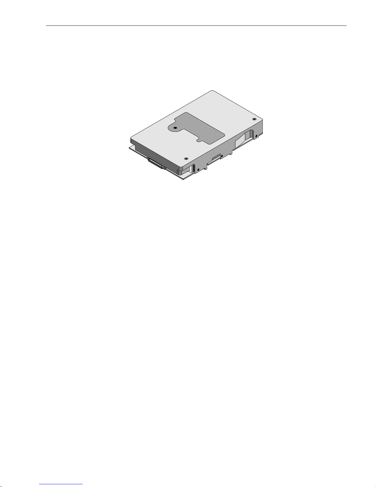
Figure 1. Cheetah 4LP FC family disc drive
(part number 77767496)


Cheetah 4LP FC Product Manual, Rev. A 3
2.0 Applicable standards and reference documentation
The drive has been developed as a system peripheral to the highest standards of design and construction. The
drive depends upon its host equipm ent to provide adequate power and environment in order to achieve optimum performance a nd compliance with applicable industry and g overnmental regulations. Special atte ntion
must be given in the areas of safety, power distribution, shielding, audible noise control, and temperat ure regulation. In particular, the drive must be securely mounted in order to guarantee the specified performance characteristics. Mounting by bott om holes must meet the requirem ents o f Section 8.5.
2.1 Standards
The Cheetah 4LP FC family complies with Seagate standards as noted in the appropriate sections of this manual and the Seagate
The Cheetah 4LP FC disc drive is a UL recognized compo nent per U L1950, CS A cert ified to CSA C22.2 No.
950-M89, and VDE certified to VDE 0805 and EN60950.
2.1.1 Electromagnetic compatibility
The drive, as delivered, is designed for s ystem integration and i nstallation into a suitable enclosure prior to
use. As such the drive is suppl ied as a subassembly and is not subject to Subpart B o f Part 15 of the FCC
Rules and Regulations nor the Radio Interference Regulations of the Canadian Departmen t of Communications.
The design characteristics of the drive serve to minimize radiation when inst alled in an enclosure that provides
reasonable shielding. As such, the drive is capable of meeting the Class B limits of the FCC Rules and Regulations of the Canadian Department of Communications when properly packaged. However, it is the user’s
responsibility to assure that the drive meets the appropriate EMI requirements in their system. Shielded I/O
cables may be required if the enclosure does not provide adequate shiel ding. If the I/O cables are ext ernal to
the enclosure, shielded cables should be used, with the shields grounded to the enclosure and to the host controller.
Fibre Channel Interface Manual
, part number 77767496 (Vol. 2).
2.1.1.1 Electromagnetic susceptibility
As a component assembly, the drive is not required to meet any susceptibility performance requirem ents. It is
the responsibility of those integrati ng t he drive wi thin their system s t o perform t hose tests re quired a nd desig n
their system to ensure that equipmen t operating in the same system as the drive or external to the sy stem
does not adversely affect the performance of the drive. See Section 5.1.1 and Table 2, DC power requirements.
2.2 Electromagnetic compliance
Seagate uses an independen t laboratory to confirm compliance to the d irectives/standard(s) for CE Marking
and C-Tick Marking. The drive was tested in a representative system for typical applications. The selected system represents the most popular characteristics for test platf or m s. The system confi gurati ons include:
• 486, Pentium, and PowerPC microprocessors
• 3.5-inch floppy disc drive
• Keyboard
• Monitor/display
• Printer
• External modem
• Mouse
Although the test system with this Seagate model complie s to the directives/standard(s), we cannot guarantee
that all systems will comply. The computer manufacturer or system integrator shall confirm EMC compli ance
and provide the appropriate marking for their product.
Electromagneti c com pli ance for the Europe an Uni on
If this model has the CE Marking it complies with the European Union requirements of the Electrom agnetic
Compatibility Di rective 89/3 36/ EEC o f 03 May 1989 as am ende d by Directive 92/3 1/EE C of 28 April 1 992 a nd
Directive 93/68/E E C of 22 Jul y 199 3.

4 Cheetah 4LP FC Product Manual, Rev. A
Australian C-Tick
If this model has the C-Tick Marking it complies with the Australia/New Zealand Standard AS/NZS3548 1995
and meets the Electrom agnetic Compatibilit y (EMC) Framewor k requirement s of Australia’s Spectrum Management Agency (SMA).
2.3 Reference documents
Cheetah 4LP FC Installation Guide
Seagate part number: 83329180
Fibre Channel Interface Manual
Seagate part number: 77767496
SCSI Interface Product Manual
Seagate part number: 77738479
ANSI Fibre Channel Documents
X3.230-1995 FC Physical and Signaling Interface (FC-PH )
X3.272-19946 FC Arbitrated Loop (FC-AL)
X3.269-1996 Fibre Channel Protocol for SCSI (FCP)
TR X3.XXX-199X Private Loop SCSI Direct Attach
ANSI Small Computer Syst em Interf ace (SCS I ) Document s
X3.131-1994 (SCSI-2)
X3.270-199X (SCSI-3) Architecture Model
SFF-8045 Specification for 40-pin SCA-2 Connector with Parallel Selecti on.
In case of conflict between this document and any referenced document, this document takes precedence.
Cheetah 4LP FC Product Manual, Rev. A 5
3.0 General description
Cheetah 4LP FC drives are random access sto rage de vices designe d to suppo rt the Fibre Chann el Arbitrate d
Loop (FC-AL) and SCS I Fibre Channel Proto col as described in the ANSI specifications, this docum ent, and
Fibre Channel Interface Manual
the
istics of this drive.
You can view the Fibre Channel interface simply as a transport vehicle for the supported command set
(ST34501FC drives use the SCSI command set). In fact, the Fibre Channel interface is unaware of the content
or meaning of the inform ation being transported. It simp ly packs the SCSI commands in frame s, transports
them to the appropriate devices, and provides error checking to ensure that the information reaches its destination accurately. Refer to the documents referenced in Section 2. 3 if you req uire additi onal informat ion about
the Fibre Channel interface, FC-AL topolog y, or the SCSI fibre channel protocol.
The head and disc assembly (HDA) is environ mentally sealed at the factory. Air recirculates within the HDA
through a non-replaceable filter to maint ain a conta min ation-free HDA environm ent.
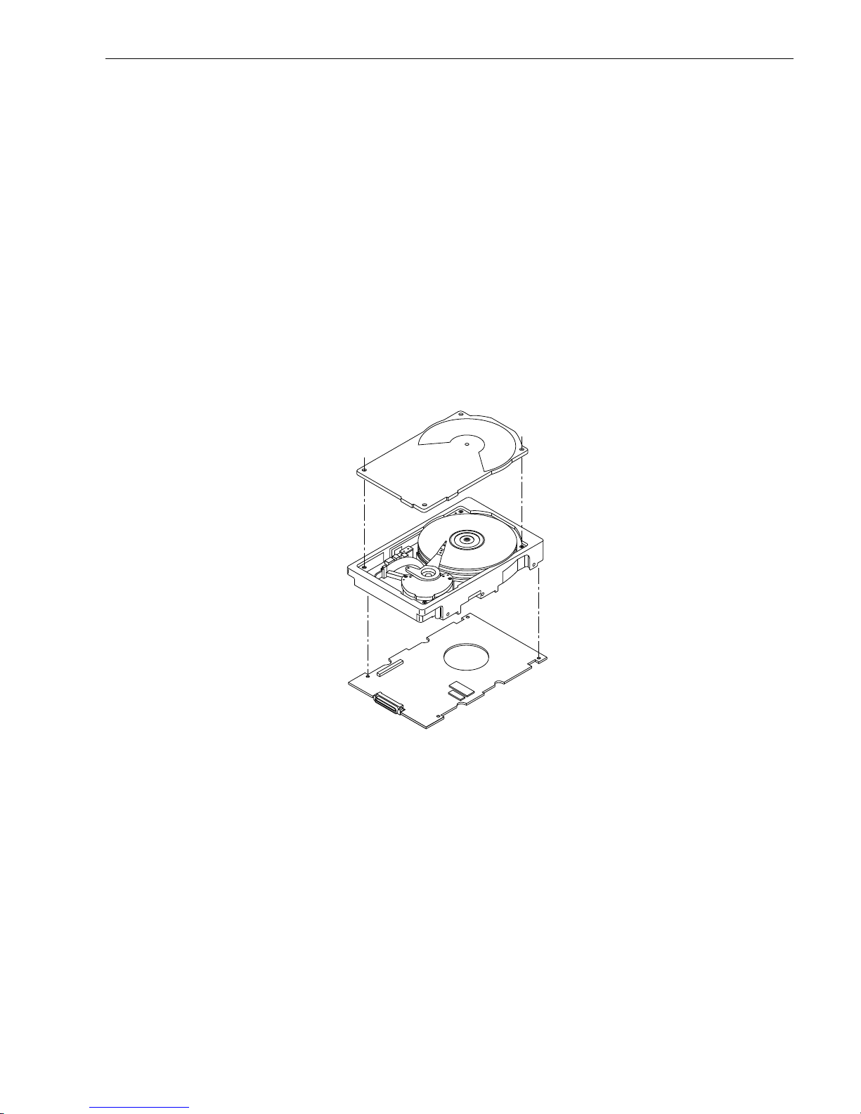
Refer to Figure 2 for an exploded view of the drive. Never disassemble the HDA. This exploded view is for
information only. Do not attempt to service item s in th e seal ed enclosure (heads, media, act uator, etc.) as this
requires special facilities. The drive contains no parts repla ceable by the user and opening the HDA for any
reason voids your warranty.
(part number 77767496) which describes the general interface chara cter-
Figure 2. Cheetah 4LP FC disc drive
Cheetah 4LP FC
drives use a dedicated la nding zone at the i nnerm ost radi us of the media to elim inat e the possibility of destroying or degrading dat a by landing in the data zone. T he heads automatical ly go to the landing
zone when power is removed from the drive.
An automatic shipping lock prevents potential damage to the heads and discs that results from movement during shipping and handling. The shipping lock disengages and the head load process begins when power is
applied to the drive.
The drives also use a high-performance actuator assembly design that provides excellent performance with
minimum power dissipation.

6 Cheetah 4LP FC Product Manual, Rev. A
3.1 Standard features
Cheetah 4LP FC drives have the following standard features:
• Integrated dual port FC-AL controll e r
• Support for FC-AL (Fibre Channel Arbitrated Loop)
• Differential copper FC drivers and receivers
• Downloadable firmware using the FC-AL interface
• Drive selection ID and configuration options are set on the FC-AL backpanel or through interface commands. Jumpers are not required on the drive.
• Fibre Channel worldwide name uniquely identifies the drive and each port
• User-selectable logical block size (180 to 4,096 bytes)
• Selectable fram e sizes from 128 to 512 bytes
• Reallocation of defects on comm and (post format )
• Industry standard 3.5-inch low profile (1 inch high) form factor dimensi on s
• Programmable logical blo ck reallocatio n scheme
• Flawed sector reallocation at format time
• Programmable autowri te and read reallo cation
• Reed-Solomon error correction code for header and data fields
• Sealed head and disc assembly (HDA)
• No preventive maintenance or adjustments required
• Dedicated head landing zone
• Automatic shipping lock
• Embedded Grey Code track address to eliminate seek errors
• Self-diagnostics perform ed at power on
• 1:1 interleave
• Zone bit recording (ZBR)
• Vertical, horizontal, or top down mounting
• Dynamic spindle brake
• 1,024 Kbyte data buffer (see Section 4.5)
• Embedded servo design
3.2 Media description
The media used on the drive has a diameter of approximately 9 5 mm (approximately 3.7 inches). The alum inum substrate is coated wit h a thin film magnetic material, overcoated with a proprietary prote ctive layer for
improved durability and environment al prot ectio n.
3.3 Performa nce
• Programmable multi-segmentable cache buffer
• 106.3 Mbytes/sec maximum insta ntaneous data transfers
• 10,033 RPM spindle; average latency = 2.99 msec
• Command queuing of up to 64 commands
• Background processing of queue
• Supports start and stop com man d s
• Adaptive seek velocity; improved seek performance
3.4 Reliability
• 1,000,000 hour MTBF (Class A computer room environment)
• Fibre Channel (FC) interface transports SC SI protocol through CRC protected frames
• LSI circuitry
• Balanced low mass rotary voice coil actuator
• Self-Monitorin g Analysis and Reporting Techno logy (S.M.A .R.T.)

Cheetah 4LP FC Product Manual, Rev. A 7
3.5 Unformatted and formatted cap aci ties
The standard OEM models are format ted to 512 bytes per block.
ST34501FC drives uses a regional sparing scheme. The drive is divided into regions that are each 12 cylinders
wide. Each region has 108 spares when formatted with 512-byte sectors.
Formatted Unformatted
ST34501FC 4.52 Gbytes 5.59 Gbytes
Users having the necessary equipm ent m ay modify the dat a b lock size b efo re issuing a form at co mma nd a n d
obtain different formatt ed capaciti es than t hose listed. User-available capacity also depe nds on the spare reallocation scheme you select. See the Mode Select command and the Format comman d in the
Interface Manual
(part number 77767496).
Fibre Channel
3.6 Factory-installe d accessorie s
OEM standard drives are shipped with the Cheetah 4LP FC Installat ion Guide (part number 833291 8 0).
3.7 Factory-instal led opti on s
You may order the following items which are incorporated at the manufacturing facili ty during production or
packaged before shipping:
• Single-unit shipping pack. The drive is normally shipped in bulk packaging t o provide maximum protection
against transit damage. Units shipped individually require additional protection as provided by the single unit
shipping pack. Users planning single unit distribution should specif y this opt ion.
3.8 User-installed accessories
The following accessorie s are available. All kits may be installed in the field.
• Evaluation kit, part number 734736 4 1.
This kit provides an adapt er card (“T-card”) to allow cable c on nectio ns fo r two FC ports and DC po we r. Two
twin axial cables, 6 feet in length, are included for the input and output connections to the FC interface.


Cheetah 4LP FC Product Manual, Rev. A 9
4.0 Performance characteristics
This section provides detailed information concerning performance-related characteristics and features of
Cheetah 4LP FC drives.
4.1 Internal drive characteristic s
ST34501FC
Drive capacity 5.59 ..................Gbytes (unformatted)
4.52 ..................Gbytes (formatted with 512-byte logical blocks)
Read/write data heads 8
Bytes per track 115,078.............Bytes (average, unformatted)
Bytes per surface 751.0 ................Mbytes (unformatt ed)
Cylinders/tracks per surface 6,526................Tracks (user accessible)
Tracks per inch 6,932 ................TPI
Peak bits per inch 135,401 ............BPI
Internal data rate 122-177............Mbits/sec (variable with zone)
Disc rotation speed 10,033 ± 0.5%..rpm
Avg rotational latency 2.99 ..................msec
4.2 Seek performanc e characte ristic s
Refer to paragraph 9.5, “FC-AL physical interface” and to the
Fibre Channel Interface Manual
(part number
77767496) for additional timing det ail s.
4.2.1 Seek time
Including drive
controller o ver h ead
(without disconnect)
Drive level
Read Write
Average Typical
Single track Typical
Full stroke Typical
1. Execution time measured from receipt of the last byte of the Command Descriptor Block (CDB) to the request for a
Status Byte Transfer to the Initiator (excluding connect/disconnect).
2. Assumes no errors and no sector has been relocated.
3. Typical access times are measured under nominal conditions of temperature, voltage, and horizontal orientatio n as
measured on a representative sample of drives.
3
3
3
7.7 8.7
0.98 1.24
18.2 19.2
1, 2
(msec)
4.2.2 Format comman d executio n time for ≥ 512-byte sectors
ST34501FC
Maximum (with verify) 60 minutes
Maximum (without verify) 36 minutes

10 Cheetah 4LP FC Product Manual, Rev. A
4.2.3 General performance characteristics
ST34501FC
Minimum sector interleave 1 to 1
Data buffer to/from disc media (one 512-byte logical block)*
Minimum 15.25 MBytes/sec
Maximum 22.12 MBytes/sec
Fibre Channel Interface maximum instantaneous transfer rate 106.3 Mbytes/sec*
Logical block sizes
Default is 512-byte data blocks
Variable (180 to 736 bytes) in multiples of 4 bytes
Variable (768 to 4,096 bytes) in multiples of 32 bytes
Read/write consecutive sectors on a track
Overhead time for head switch in sequential mode
Overhead time for one track cylinder switch in sequential mode
Average rotational latency
*Assumes no errors and no relocated logical blocks.
Yes
0.798 msec
<1.064 msec (typical)
2.99 msec
4.3 Start/stop time
If the Motor Start option is disabled, the drive become s ready within 30 seconds aft er DC power is applied. If a
recoverable error condition is detected during the start sequence, the drive executes a recovery procedure and
the time to become ready may exceed 30 seconds. During the start sequence, the drive responds to some
commands over the FC-AL interface. Stop time is less than 30 seconds (maximum) from removal of DC power.
If the Motor Start op tion is enabled, the i nternal controller accept s the commands l isted in the
Interface Manual
less than 3 seconds after DC power has bee n applied. After the Moto r Start command has
Fibre Channel
been received, the drive becomes ready for normal operations within 30 seconds (excluding the error recovery
procedure). The Motor Start command can also be used to command the drive to stop the spindle.
There is no power control switch on the drive.
4.4 Prefetch/multi-se gmen ted cach e contro l
The drive provides a prefetch /multi-segment ed cache algorit hm that in many cases can enhance syst em performance. To select thi s feature the host sends the Mode Select comm and with the proper values in the applicable bytes in page 08h. Default is prefetch and read cache enabled.
If the Prefetch feat ure is ena bled, data in co ntiguous log ical bl o cks on the disc imme diat ely beyon d that wh ich
was requested by a Read comman d are retrieved and stored in the buffer for immediate transfer from the
buffer to the host on subsequent Read com mands that request those logical blocks (th is is true even if cache
operation is disabled). To enable Prefetch, use Mode Sel ect page 08h, byte 12 , bit 5 (Disable Read Ahea d DRA bit). DRA bit = 0 enables prefetch.
Since data that is prefetched replaces data alrea dy in some buffer segments, the host can limit the amo unt of
prefetch data to optimize system performan ce. The Max Prefetch fiel d (bytes 8 and 9) limits the amount of
prefetch. The drive does not use the Prefetch Ceili ng fiel d (bytes 10 and 11).
4.5 Cache operation
Note. Refer to the
Fibre Channel Interface Man ual
Of the 1,024 Kbytes physical buffer space in the drive , 967.5 Kbytes can be used as a cache. The cache can
be divided into logical segments from which data is read and to which dat a is written.
for more detail concerning the cache bits.

Cheetah 4LP FC Product Manual, Rev. A 11
The drive keeps track of the logical block addresses of the data stored in each segment of the cache. If the
cache is enabled (see RCD bit in the
Fibre Channel I nte rface Manual
), data requested by the host with a read
command is retrieved from the cache, if possible, before any disc access is initiated. Data in contiguous logical
blocks immediately beyo nd that requested by the Read co mma nd ca n be retrieved and stored in the cache fo r
immediate tra nsfer to the initiator on subsequent read commands. This is referred to as the prefetch operation.
Since data that is pref etched m ay repl a ce data alre ady in the cache segm ent , an init iator can limit the am ount
of prefetch data to optimize system performance. The drive never prefetches more sectors than the num ber
specified in bytes 8 and 9 of Mode page 08h. If the cache is not enabled, 967.5 Kbyte s of the buffer are used
as a circular buffer for read/writes, with no prefetch operation and no se gme nted cache operation.
The following is a simplified description of the prefetch/cache operat ion:
Case A—read command is received and the first logical bloc k is already in cache:
1. Drive transfers to the initiator the first logical blo c k requested plus all subse quent cont iguou s logical blocks
that are already in the cache. This data may be in multiple segments.
2. When a requested logical block is reached that is not in a ny segme nt, the drive f etches it and any remain-
ing requested logical block addresses from the disc and pu ts them in a segment of the cache. The drive
transfers the remaining requested logical blocks from the cache to the initiator in accordance with the
“buffer-full” ratio specification given in Mode Select Disconn ect/Reconnect parame ters, page 02h.
3. The drive prefetches additional lo gical blocks contiguo us to those transferred in step 2 above and stores
them in the segment. The drive stops filling the segment when the maximum prefe tch value has been
transferred.
Case B—read command i s recei ved and the f irst logical block addre ss requested is not in any segment of the
cache.
1. The drive fetches the req uested logica l blocks from the disc and t ransfers them into a segment, and then
from there to the initiator in accordance with the “buffer-ful l” ratio specification given in Mode Select Disconnect/Reconnect paramet ers, page 02h.
2. The drive prefetches additional logical blocks contigu ous to tho se transferred in Case A, step 2 above and
stores them in the segment. The drive st ops filling the segment when the maximum prefetch value ha s
been transferred.
During a prefetch, the drive crosses a cyli nder bo undary to fe tch data only if the D i scontinu ity (DI S C) bit is set
to 1 in bit 4 of byte 2 of the Mode Select parameters page 08h. Default is zero for bit 4.
Each cache segment is actually a self-contai ned circular buffer whose length is an integer number of logical
blocks. The wrap-around capability of the individual segmen ts greatly enhances the cache’s overall performance, allowing a wide range of user-selectable configurations. The drive supports operation of any integer
number of segment s from 1 to 16. Divide the 967 .5 Kb ytes i n the b uffer b y the number of segme nts to get the
segment size. Default is 3 segments.
4.5.1 Caching write data
Write caching is a write operat ion b y the drive that ma kes use of a dri ve buffer storage area wh ere the dat a to
be written to the medium is stored while the drive performs th e Write comm and.
Write caching is enabled independently of read caching. Write caching is disabled by def ault on ST34501FC
drives. To enable the write cache, use the Write Caching Enable (WCE) bit.
For write caching, the same buffer space and segm ent ation is used as set up for read fun ctions. Whe n a write
command is issued, the cache i s first checked to see if any logical blocks that are to be written are al ready
stored in the cache from a previous read or writ e command. If there are, the respective cache segment s are
cleared. The new data is cached for subsequent read commands.
If a 10-byte CDB Write command (2Ah) is issued wit h the data page out (DPO) bit set to 1, no write data is
cached, but the cache segments are still checked and cleared, if need be, for any logical blocks tha t are being
written.
 Loading...