

Page 1

. . . . . . . . . . . . . . . . . . . . . . . . . . . . . . . . . . . . . . . . . . . . . . . . .
Cheetah 4LP Family:
. . . . . . . . . . . . . . . . . . . . . . . . . . . . . . . . . . . . . . . . . . . . . . . . .
. . . . . . . . . . . . . . . . . . . . . . . . . . . . . . . . . . . . . . . . . . . . . . . . .
. . . . . . . . . . . . . . . . . . . . . . . . . . . . . . . . . . . . . . . . . . . . . . . . .
. . . . . . . . . . . . . . . . . . . . . . . . . . . . . . . . . . . . . . . . . . . . . . . . .
ST34501N/W/WC/WD/DC
Product Manual, Volume 1
Page 2

Page 3

. . . . . . . . . . . . . . . . . . . . . . . . . . . . . . . . . . . . . . . . . . . . . . . . .
Cheetah 4LP Family:
. . . . . . . . . . . . . . . . . . . . . . . . . . . . . . . . . . . . . . . . . . . . . . . . .
. . . . . . . . . . . . . . . . . . . . . . . . . . . . . . . . . . . . . . . . . . . . . . . . .
. . . . . . . . . . . . . . . . . . . . . . . . . . . . . . . . . . . . . . . . . . . . . . . . .
. . . . . . . . . . . . . . . . . . . . . . . . . . . . . . . . . . . . . . . . . . . . . . . . .
ST34501N/W/WC/WD/DC
Product Manual, Volume 1
Page 4

© 1997 Seagate T echnology, Inc. All rights reserved
Publication number: 83329120 , Rev. B
July 1997
Seagate, Seagate Technol ogy, and the Seagate l ogo are registered tradem arks of Seagate Technology, Inc. Cheetah, SeaFAX, SeaFONE, SeaNET, SeaTDD, and SeaBOARD are either tradema rks or
registered trademarks of Seagate Technology, Inc. or one of its subsidiaries. All other trademarks o r
registered trademarks are the property of their respective owners.
Seagate reserves the right to change, without not ice, product offerings or specifications. No part of
this publication may be reproduced in any form without written permission of Seagate Technology, Inc.
Page 5

Revision status summary sheet
Revision Date Writer/Engineer Sheets Affected
A Issue 04/07/97 D. Ashby/G. Olson 1/1, v thru vii, 1 thru 78
B 06/26/97 D. Ashby/G. Olson 9, 10, 14, 15, 18, 20, 22, 29, 30, 49,
52, 56, and 69.
Notice.
Product Manual 83329120 is Volume 1 of a two-volume document with the SCSI interface information in
the Volume 2,
If the SCSI interface information is needed, the Volume 2 interface manual should be ordered, part
number 77738479.
SCSI Interface Product Manual
, part number 77738479.
Page 6

Page 7

Cheetah 4LP Product Manual, Rev. B v
Contents
1.0 Scope . . . . . . . . . . . . . . . . . . . . . . . . . . . . . . . . . . . . . . . . . . . . . . . . . . . . . . . . . . . . . . . . . . . . . . . . . . 1
2.0 Applicable standards and reference documentati on . . . . . . . . . . . . . . . . . . . . . . . . . . . . . . . . . . . . 3
2.1 Standards. . . . . . . . . . . . . . . . . . . . . . . . . . . . . . . . . . . . . . . . . . . . . . . . . . . . . . . . . . . . . . . . . 3
2.1.1 Electromagnetic com pati bili ty . . . . . . . . . . . . . . . . . . . . . . . . . . . . . . . . . . . . . . . . . . 3
2.1.2 Electromagnetic susceptibility . . . . . . . . . . . . . . . . . . . . . . . . . . . . . . . . . . . . . . . . . . 3
2.2 Electromagne tic compliance . . . . . . . . . . . . . . . . . . . . . . . . . . . . . . . . . . . . . . . . . . . . . . . . . . 3
2.3 Reference documents . . . . . . . . . . . . . . . . . . . . . . . . . . . . . . . . . . . . . . . . . . . . . . . . . . . . . . . 4
3.0 General descri p tion. . . . . . . . . . . . . . . . . . . . . . . . . . . . . . . . . . . . . . . . . . . . . . . . . . . . . . . . . . . . . . . 5
3.1 Standard features. . . . . . . . . . . . . . . . . . . . . . . . . . . . . . . . . . . . . . . . . . . . . . . . . . . . . . . . . . . 7
3.2 Media characteristic s . . . . . . . . . . . . . . . . . . . . . . . . . . . . . . . . . . . . . . . . . . . . . . . . . . . . . . . . 7
3.3 Performance. . . . . . . . . . . . . . . . . . . . . . . . . . . . . . . . . . . . . . . . . . . . . . . . . . . . . . . . . . . . . . . 7
3.4 Reliability . . . . . . . . . . . . . . . . . . . . . . . . . . . . . . . . . . . . . . . . . . . . . . . . . . . . . . . . . . . . . . . . . 7
3.5 Unformatt ed and formatted capacit ies . . . . . . . . . . . . . . . . . . . . . . . . . . . . . . . . . . . . . . . . . . . 8
3.6 Programmabl e drive capacity. . . . . . . . . . . . . . . . . . . . . . . . . . . . . . . . . . . . . . . . . . . . . . . . . . 8
3.7 Factory installed accessories . . . . . . . . . . . . . . . . . . . . . . . . . . . . . . . . . . . . . . . . . . . . . . . . . . 8
3.8 Options (factory install ed ) . . . . . . . . . . . . . . . . . . . . . . . . . . . . . . . . . . . . . . . . . . . . . . . . . . . . . 8
3.9 Accessories (user installed) . . . . . . . . . . . . . . . . . . . . . . . . . . . . . . . . . . . . . . . . . . . . . . . . . . . 8
4.0 Performa nce cha racteri sti c s . . . . . . . . . . . . . . . . . . . . . . . . . . . . . . . . . . . . . . . . . . . . . . . . . . . . . . . 9
4.1 Internal drive characteristics (transparent to user). . . . . . . . . . . . . . . . . . . . . . . . . . . . . . . . . . 9
4.2 SCSI performance characte ristics (visible to user) . . . . . . . . . . . . . . . . . . . . . . . . . . . . . . . . . 9
4.2.1 Access time . . . . . . . . . . . . . . . . . . . . . . . . . . . . . . . . . . . . . . . . . . . . . . . . . . . . . . . 9
4.2.2 Format command executi on time (minute s) . . . . . . . . . . . . . . . . . . . . . . . . . . . . . . . 9
4.2.3 Generalized performance characteristics . . . . . . . . . . . . . . . . . . . . . . . . . . . . . . . . . 9
4.3 Start/st op tim e . . . . . . . . . . . . . . . . . . . . . . . . . . . . . . . . . . . . . . . . . . . . . . . . . . . . . . . . . . . . 10
4.4 Prefetch/multi-segmented cache control . . . . . . . . . . . . . . . . . . . . . . . . . . . . . . . . . . . . . . . . 10
4.5 Cache operation. . . . . . . . . . . . . . . . . . . . . . . . . . . . . . . . . . . . . . . . . . . . . . . . . . . . . . . . . . . 11
4.5.1 Caching write data . . . . . . . . . . . . . . . . . . . . . . . . . . . . . . . . . . . . . . . . . . . . . . . . . 11
4.5.2 Prefetch operation . . . . . . . . . . . . . . . . . . . . . . . . . . . . . . . . . . . . . . . . . . . . . . . . . 12
5.0 Reliabil ity sp eci ficati on s . . . . . . . . . . . . . . . . . . . . . . . . . . . . . . . . . . . . . . . . . . . . . . . . . . . . . . . . . 13
5.1 Error rates . . . . . . . . . . . . . . . . . . . . . . . . . . . . . . . . . . . . . . . . . . . . . . . . . . . . . . . . . . . . . . . 13
5.1.1 Environmental interference. . . . . . . . . . . . . . . . . . . . . . . . . . . . . . . . . . . . . . . . . . . 13
5.1.2 Read errors. . . . . . . . . . . . . . . . . . . . . . . . . . . . . . . . . . . . . . . . . . . . . . . . . . . . . . . 13
5.1.3 Write errors . . . . . . . . . . . . . . . . . . . . . . . . . . . . . . . . . . . . . . . . . . . . . . . . . . . . . . . 13
5.1.4 Seek errors. . . . . . . . . . . . . . . . . . . . . . . . . . . . . . . . . . . . . . . . . . . . . . . . . . . . . . . 1 3
5.2 Reliability and service. . . . . . . . . . . . . . . . . . . . . . . . . . . . . . . . . . . . . . . . . . . . . . . . . . . . . . . 14
5.2.1 Mean time between failure . . . . . . . . . . . . . . . . . . . . . . . . . . . . . . . . . . . . . . . . . . . 14
5.2.2 Preventive maintenance . . . . . . . . . . . . . . . . . . . . . . . . . . . . . . . . . . . . . . . . . . . . . 14
5.2.3 Service life . . . . . . . . . . . . . . . . . . . . . . . . . . . . . . . . . . . . . . . . . . . . . . . . . . . . . . . 14
5.2.4 Service philosophy . . . . . . . . . . . . . . . . . . . . . . . . . . . . . . . . . . . . . . . . . . . . . . . . . 14
5.2.5 Service tools. . . . . . . . . . . . . . . . . . . . . . . . . . . . . . . . . . . . . . . . . . . . . . . . . . . . . . 14
5.2.6 Hot plugging Cheetah 9 disc drives . . . . . . . . . . . . . . . . . . . . . . . . . . . . . . . . . . . . 14
5.2.7 S.M.A.R.T. . . . . . . . . . . . . . . . . . . . . . . . . . . . . . . . . . . . . . . . . . . . . . . . . . . . . . . . 15
5.2.8 Product warranty . . . . . . . . . . . . . . . . . . . . . . . . . . . . . . . . . . . . . . . . . . . . . . . . . . . 16
6.0 Physical/electrical specifications . . . . . . . . . . . . . . . . . . . . . . . . . . . . . . . . . . . . . . . . . . . . . . . . . . 17
6.1 AC power requirements . . . . . . . . . . . . . . . . . . . . . . . . . . . . . . . . . . . . . . . . . . . . . . . . . . . . . 17
6.2 DC power requirements . . . . . . . . . . . . . . . . . . . . . . . . . . . . . . . . . . . . . . . . . . . . . . . . . . . . . 17
6.2.1 Conducted noise immunity . . . . . . . . . . . . . . . . . . . . . . . . . . . . . . . . . . . . . . . . . . . 18
6.2.2 Power sequencing . . . . . . . . . . . . . . . . . . . . . . . . . . . . . . . . . . . . . . . . . . . . . . . . . 1 8
6.2.3 12 V current profile . . . . . . . . . . . . . . . . . . . . . . . . . . . . . . . . . . . . . . . . . . . . . . . . . 18
6.3 Power dissipation . . . . . . . . . . . . . . . . . . . . . . . . . . . . . . . . . . . . . . . . . . . . . . . . . . . . . . . . . . 19
6.4 Environmenta l limits . . . . . . . . . . . . . . . . . . . . . . . . . . . . . . . . . . . . . . . . . . . . . . . . . . . . . . . . 19
6.4.1 Temperature . . . . . . . . . . . . . . . . . . . . . . . . . . . . . . . . . . . . . . . . . . . . . . . . . . . . . . 20
Page 8

vi Cheetah 4LP Product Manual, Rev. B
6.4.2 Relative humidit y . . . . . . . . . . . . . . . . . . . . . . . . . . . . . . . . . . . . . . . . . . . . . . . . . . .22
6.4.3 Effective altitude (sea level). . . . . . . . . . . . . . . . . . . . . . . . . . . . . . . . . . . . . . . . . . .22
6.4.4 Shock and vibration . . . . . . . . . . . . . . . . . . . . . . . . . . . . . . . . . . . . . . . . . . . . . . . . .22
6.4.5 Air cleanliness . . . . . . . . . . . . . . . . . . . . . . . . . . . . . . . . . . . . . . . . . . . . . . . . . . . . .24
6.4.6 Acoustics . . . . . . . . . . . . . . . . . . . . . . . . . . . . . . . . . . . . . . . . . . . . . . . . . . . . . . . . .24
6.4.7 Electromagnetic susceptibility . . . . . . . . . . . . . . . . . . . . . . . . . . . . . . . . . . . . . . . . .24
6.5 Mechanical specif icati ons . . . . . . . . . . . . . . . . . . . . . . . . . . . . . . . . . . . . . . . . . . . . . . . . . . . .25
7.0 Defect and error man agem e nt . . . . . . . . . . . . . . . . . . . . . . . . . . . . . . . . . . . . . . . . . . . . . . . . . . . . .29
7.1 Drive internal defects. . . . . . . . . . . . . . . . . . . . . . . . . . . . . . . . . . . . . . . . . . . . . . . . . . . . . . . .29
7.2 Drive error recovery procedures . . . . . . . . . . . . . . . . . . . . . . . . . . . . . . . . . . . . . . . . . . . . . . .29
7.3 SCSI systems errors . . . . . . . . . . . . . . . . . . . . . . . . . . . . . . . . . . . . . . . . . . . . . . . . . . . . . . . .30
8.0 Installati on . . . . . . . . . . . . . . . . . . . . . . . . . . . . . . . . . . . . . . . . . . . . . . . . . . . . . . . . . . . . . . . . . . . . .31
8.1 Drive ID/option select h ea der . . . . . . . . . . . . . . . . . . . . . . . . . . . . . . . . . . . . . . . . . . . . . . . . .31
8.1.1 Notes for Figures 9, 10, and 11. . . . . . . . . . . . . . . . . . . . . . . . . . . . . . . . . . . . . . . .35
8.1.2 Function description. . . . . . . . . . . . . . . . . . . . . . . . . . . . . . . . . . . . . . . . . . . . . . . . .36
8.2 Drive orientation . . . . . . . . . . . . . . . . . . . . . . . . . . . . . . . . . . . . . . . . . . . . . . . . . . . . . . . . . . .37
8.3 Cooling . . . . . . . . . . . . . . . . . . . . . . . . . . . . . . . . . . . . . . . . . . . . . . . . . . . . . . . . . . . . . . . . . .37
8.3 . 1 A i r fl o w . . . . . . . . . . . . . . . . . . . . . . . . . . . . . . . . . . . . . . . . . . . . . . . . . . . . . . . . . . .37
8.4 Drive mounting . . . . . . . . . . . . . . . . . . . . . . . . . . . . . . . . . . . . . . . . . . . . . . . . . . . . . . . . . . . .38
8.5 Grounding . . . . . . . . . . . . . . . . . . . . . . . . . . . . . . . . . . . . . . . . . . . . . . . . . . . . . . . . . . . . . . . .38
9.0 Interface requiremen t s. . . . . . . . . . . . . . . . . . . . . . . . . . . . . . . . . . . . . . . . . . . . . . . . . . . . . . . . . . . .39
9.1 General description . . . . . . . . . . . . . . . . . . . . . . . . . . . . . . . . . . . . . . . . . . . . . . . . . . . . . . . . .39
9.2 SCSI interface messages supported. . . . . . . . . . . . . . . . . . . . . . . . . . . . . . . . . . . . . . . . . . . .39
9.3 SCSI interface command s supported . . . . . . . . . . . . . . . . . . . . . . . . . . . . . . . . . . . . . . . . . . .40
9.3.1 Inquiry Vital Product data. . . . . . . . . . . . . . . . . . . . . . . . . . . . . . . . . . . . . . . . . . . . .4 3
9.3.2 Mode Sense data . . . . . . . . . . . . . . . . . . . . . . . . . . . . . . . . . . . . . . . . . . . . . . . . . . .43
9.4 SCSI bus conditions and miscellaneous features support ed . . . . . . . . . . . . . . . . . . . . . . . . .47
9.5 Synchronous data transfer . . . . . . . . . . . . . . . . . . . . . . . . . . . . . . . . . . . . . . . . . . . . . . . . . . .48
9.5.1 Synchronous data transfer periods supported. . . . . . . . . . . . . . . . . . . . . . . . . . . . .48
9.5.2 REQ/ACK offset. . . . . . . . . . . . . . . . . . . . . . . . . . . . . . . . . . . . . . . . . . . . . . . . . . . .48
9.6 Physi cal interf ac e . . . . . . . . . . . . . . . . . . . . . . . . . . . . . . . . . . . . . . . . . . . . . . . . . . . . . . . . . .48
9.6.1 DC cable and connector . . . . . . . . . . . . . . . . . . . . . . . . . . . . . . . . . . . . . . . . . . . . .48
9.6.2 SCSI interface physical description . . . . . . . . . . . . . . . . . . . . . . . . . . . . . . . . . . . . .51
9.6.3 SCSI interface cable requiremen ts . . . . . . . . . . . . . . . . . . . . . . . . . . . . . . . . . . . . .51
9.6.4 Mating connectors . . . . . . . . . . . . . . . . . . . . . . . . . . . . . . . . . . . . . . . . . . . . . . . . . .52
9.7 Electrical description . . . . . . . . . . . . . . . . . . . . . . . . . . . . . . . . . . . . . . . . . . . . . . . . . . . . . . . .64
9.7.1 Single-ended drivers/receivers . . . . . . . . . . . . . . . . . . . . . . . . . . . . . . . . . . . . . . . .64
9.7.2 Differential drivers/receivers . . . . . . . . . . . . . . . . . . . . . . . . . . . . . . . . . . . . . . . . . .65
9.8 Terminator re quirem ent s. . . . . . . . . . . . . . . . . . . . . . . . . . . . . . . . . . . . . . . . . . . . . . . . . . . . .67
9.9 Terminator power . . . . . . . . . . . . . . . . . . . . . . . . . . . . . . . . . . . . . . . . . . . . . . . . . . . . . . . . . .67
9.10 Disc drive SCSI timing. . . . . . . . . . . . . . . . . . . . . . . . . . . . . . . . . . . . . . . . . . . . . . . . . . . . . . .68
10.0 Seagate technical support servi ces . . . . . . . . . . . . . . . . . . . . . . . . . . . . . . . . . . . . . . . . . . . . . . . . .71
Page 9

Cheetah 4LP Product Manual, Rev. B vii
Figur e s
Figure 1. Cheetah 9 family drive . . . . . . . . . . . . . . . . . . . . . . . . . . . . . . . . . . . . . . . . . . . . . . . . . . . . . . . 1
Figure 2. Cheetah 9 family drive . . . . . . . . . . . . . . . . . . . . . . . . . . . . . . . . . . . . . . . . . . . . . . . . . . . . . . . 6
Figure 3. Typical Cheetah 9 family drive +12 V current profile . . . . . . . . . . . . . . . . . . . . . . . . . . . . . . . 19
Figure 4. Locations of PCB components listed in Table 3. . . . . . . . . . . . . . . . . . . . . . . . . . . . . . . . . . . 21
Figure 5. Recommended mounting. . . . . . . . . . . . . . . . . . . . . . . . . . . . . . . . . . . . . . . . . . . . . . . . . . . . 23
Figure 6. Mounting configurati on dim ensions for m odel “N ” . . . . . . . . . . . . . . . . . . . . . . . . . . . . . . . . . 25
Figure 7. Mounting configurati on dimensions for m odels “W” and “WD ”. . . . . . . . . . . . . . . . . . . . . . . . 26
Figure 8. Mounting configurati on dimensions for m odels “WC” and “DC”. . . . . . . . . . . . . . . . . . . . . . . 27
Figure 9. Model “N” option select jumper connectors . . . . . . . . . . . . . . . . . . . . . . . . . . . . . . . . . . . . . . 32
Figure 10. Cheetah 9 family drive ID select for models “W” and “WD” . . . . . . . . . . . . . . . . . . . . . . . . . . 33
Figure 11. Model ST19101WC/ DC option select jum per connecto rs . . . . . . . . . . . . . . . . . . . . . . . . . . . 34
Figure 12. Air flow (suggested) . . . . . . . . . . . . . . . . . . . . . . . . . . . . . . . . . . . . . . . . . . . . . . . . . . . . . . . . 37
Figure 13. Physical interface for “N” model drives . . . . . . . . . . . . . . . . . . . . . . . . . . . . . . . . . . . . . . . . . . 49
Figure 14. Model “W” and “WD” drive physical interface (68-pin J1 SCSI I/O connector). . . . . . . . . . . . 50
Figure 15. Model “WC” and “DC” drive physical interface (80-pin J1 SCSI I/O connector and
DC power connector) . . . . . . . . . . . . . . . . . . . . . . . . . . . . . . . . . . . . . . . . . . . . . . . . . . . . . . . 5 0
Figure 16. SCSI daisy-chain interface cabling. . . . . . . . . . . . . . . . . . . . . . . . . . . . . . . . . . . . . . . . . . . . . 54
Figure 17. Nonshielded 50-pin SCSI device connector used on “N” models . . . . . . . . . . . . . . . . . . . . . 55
Figure 18. Nonshielded 68-pin SCSI device connector used on “W” and “WD” models . . . . . . . . . . . . . 56
Figure 19. Nonshielded 80-pin SCSI “SCA-2” connector used on “WC” and “DC” models. . . . . . . . . . . 57
Figure 20. Single-ended transmitters and receivers . . . . . . . . . . . . . . . . . . . . . . . . . . . . . . . . . . . . . . . . 64
Figure 21. Typical differential I/O line transmitter/receiver and external terminat ors . . . . . . . . . . . . . . . 66
Page 10

Page 11
Cheetah 4LP Product Manual, Rev. B 1
1.0 Scope
This manual describes the Seagate Technology®, Inc. Cheetah 4LP ™ disc drives.
Cheetah 4LP drives support the small cumputer system interface (SCSI) as described in the ANSI SCSI,
SCSI-2, and SCS I-3 (Fast-20) in terface specif ications to the e xtent de scribed in this ma nual. The
face Product Manual
(part number 77738479) describes general SCSI interface characteristics of this and
other families of Seagate drives.
From this point on in this product m anual the refere nce to Cheetah 4LP models is referred to as “the drive”
(unless references to individual models are necessary).
SCSI Int er-
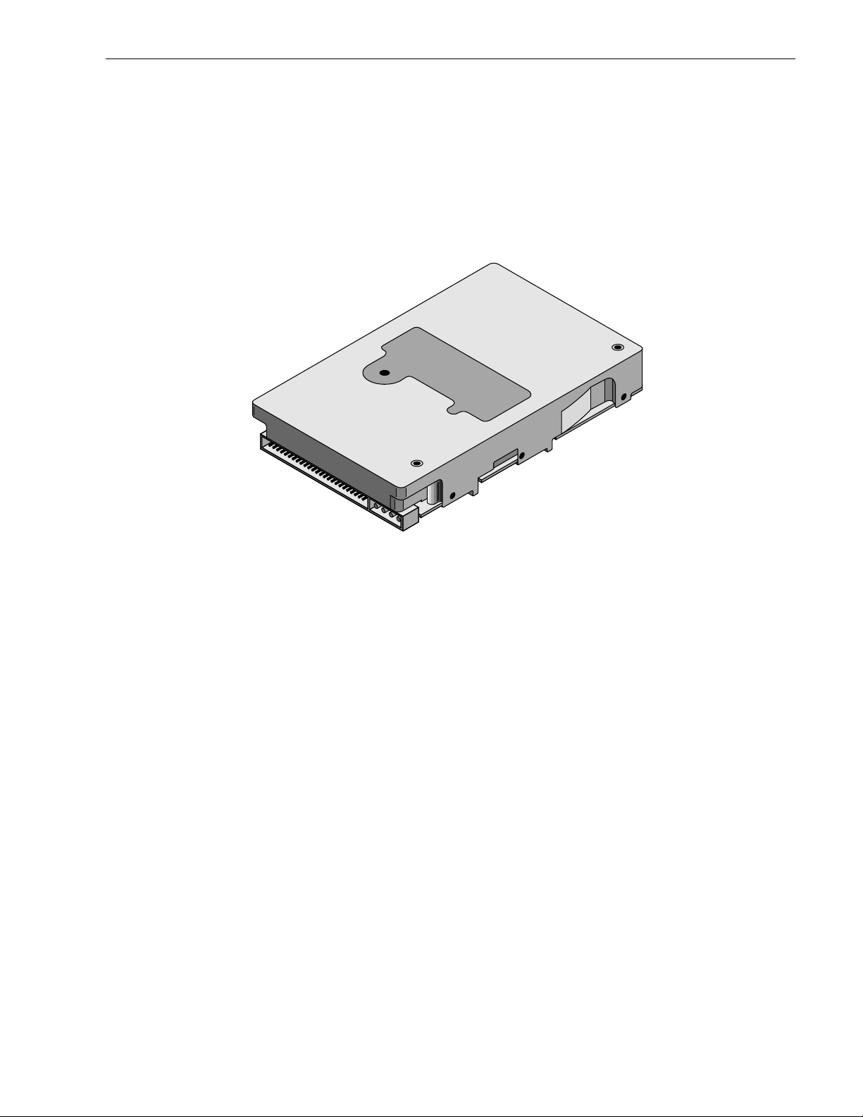
*Model “N” version with 50-pin SCSI I/O connector
Figure 1. Cheetah 4LP family drive
Page 12

Page 13

Cheetah 4LP Product Manual, Rev. B 3
2.0 Applicable standards and reference documentation
The drive has been developed as a system peripheral to the highest standards of design and construction. The
drive depends upon its host equipm ent to provide adequate power and environment in order to achieve optimum performance a nd compliance with applicable industry and g overnmental regulations. Special atte ntion
must be given in the areas of safety, power distribution, shielding, audible noise control, and temperature regulation. In particular, the drive must be se curely mo unte d in order to guarant ee the spe cifi ed performa nce characteristics. Mounting by bott om holes must meet the requirem ents o f Section 8.4.
2.1 Standards
The Cheetah 4LP family com pli es wit h Seagat e st andards a s not ed i n the appropria te section s of this manua l
and the Seagate
The Cheetah 4LP dis c drive is a UL recognized component per UL1950, CSA certif ied to CSA C22. 2 No. 950M89, and VDE certified to VDE 0805 and EN60950.
2.1.1 Electromagnetic compatibility
The drive, as delivered, is designed for s ystem integration and i nstallation into a suitable enclosure prior to
use. As such the drive is suppl ied as a subassembly and is not subject to Subpart B o f Part 15 of the FCC
Rules and Regulations nor the Radio Interference Regulations of the Canadian Departmen t of Communications.
The design characteristics of the drive serve to minimize radiation when inst alled in an enclosure that provides
reasonable shielding. As such, the drive is capable of meeting the Class B limits of the FCC Rules and Regulations of the Canadian Department of Communications when properly packaged. However, it is the user’s
responsibility to assure that the drive meets the appropriate EMI requirements in their system. Shielded I/O
cables may be required if the enclosure does not provide adequate shiel ding. If the I/O cables are ext ernal to
the enclosure, shielded cables should be used, with the shields grounded to the enclosure and to the host controller.
SCSI Interface Product Manual
(volume 2), part number 77738479.
2.1.2 Electromagnetic susceptibility
As a component assembly, the drive is not required to meet any susceptibility performance requirem ents. It is
the responsibility of those integrati ng t he drive wi thin their system s t o perform t hose tests re quired a nd desig n
their system to ensure that equipmen t operating in the same system as the drive or external to the sy stem
does not adversely affect the performance of the drive. See Section 5.1.1 and Table 2, DC power requirements.
2.2 Electromagnetic compliance
Seagate uses an independen t laboratory to confirm compliance to the d irectives/standard(s) for CE Marking
and C-Tick Marking. The drive was tested in a representative system for typical applications. The selected system represents the most popular characteristics for test platf or m s. The system confi gurati ons include:
• 486, Pentium, and PowerPC microprocessors
• 3.5-inch floppy disc drive
• Keyboard
• Monitor/display
• Printer
• External modem
• Mouse
Although the test system with this Seagate model complie s to the directives/standard(s), we cannot guarantee
that all systems will comply. The computer manufacturer or system integrator shall confirm EMC compli ance
and provide CE Marking and C-Tick Marking for their product.
Electromagneti c com pli ance for the Europe an Uni on
If this model has the CE Marking it complies with the European Union requirements of the Electrom agnetic
Compatibility Di rective 89/3 36/ EEC o f 03 May 1989 as am ende d by Directive 92/3 1/EE C of 28 April 1 992 a nd
Directive 93/68/E E C of 22 Jul y 199 3.
Page 14

4 Cheetah 4LP Product Manual, Rev. B
Australian C-Tick
If this model has the C-Tick Marking it complies with the Australia/New Zealand Standard AS/NZS3548 1995
and meets the Electrom agnetic Compatibilit y (EMC) Framewor k requirement s of Australia’s Spectrum Management Agency (SMA).
2.3 Reference documents
Cheetah 4LP Installat ion Gu ide
SCSI Interface Product Manual
ANSI small computer system interface (SCSI) document numbers:
X3.131-1994 SCSI-2
X3T10/855D rev. 15a SPI
X3T10/1071D rev. 6 Fast-20 (also called “Ultra SCSI”)
SFF-8046 Specification for 80-pin SCA connector for SCSI disk drives
Package Test Spe cification Seagate P/N 30190-001 (under 100 lb.)
Package Test Speci fication Seagate P/N 30191-001 (over 100 lb.)
In case of conflict between this document and any referenced document, this document takes precedence.
(volume 2) Seagate P/N 77738479
Seagate P/N 83329110
Page 15

Cheetah 4LP Product Manual, Rev. B 5
3.0 General description
Cheetah 4LP drives combine magnetoresistive (MR) heads, partial response/maximum likelihood (PRML) read
channel electronics, embedded servo technology, and a SCSI-3 (Fast-20) interface to provide high performance, high capacity dat a storage for a variety of systems including engineering workstations, network servers, mainframes, and supe rcompu ters.
Fast-20 (also known as Ult ra SCS I) is a negotiated transfer rat e. This transfer rate w ill o ccur only if your host
adapter also supports Fast-20 data transfer rates. This drive also operates at SCSI-1 and SCSI-2 data transf er
rates for backward compatibility with non-Fast-20 capable SCSI host adapt ers.
Table 1 lists the features that differe ntia te the various Che etah 4LP SCSI -3 Fast -20 (Ul tra SCSI ) mode ls.
Table 1. Dri ve model number vs. differentiati ng featur e s
Model number
Number
of heads I/O circuit type
Number of I/O
connector pins
Number of I/O
data bus bits
ST34501N 8 single-ended 50 8
ST34501W 8 single-ended 68 16
ST34501WD 8 differential 68 16
ST34501WC 8 single-ended 80 16
ST34501DC 8 differential 80 16
The drive records and recovers data on 3.5-inch (86 mm) non-removeable discs.
The drive supports the Smal l Computer System Interf ace (SCSI) as described in the ANSI SCSI-2 interface
specifications to the extent described in this manual (volume 1), which defines the product perform ance characteristics of the Cheetah 4LP family of drives, and the
SCSI Interface Product Manual
(volume 2), P/N
77738479, which describes the general interface characteristics of this and other families of Seaga te SCSI
drives.
The drive’s interface supports multiple initiators, disconnect/reconnect, self-configuring host software, and
automatic features that relieve the host from the necessity of knowing the physical characteristics of the targets
(logical block addressing is used).
The head and disc assembly (HDA) is sealed at the factory. Air circulates within the HDA through a nonreplaceable filter to maintain a contami nati on-fre e HDA environment .
Refer to Figure 2 for a n exploded view of the drive. This explo ded view is for information on ly—never disassemble the HDA and do not attempt to service it em s in t he s e a led enclosure (heads, m edia, actuator, etc.) as
this requires special facilities. The drive contains no replaceable parts. Opening th e HDA voids your warranty.
Cheetah 4LP drives use a dedicated landing zone at the innermost radius of the media to eliminate the possibility of destroying or degradi ng data b y landing in the data zone. The dri ve automa tically goes t o the landin g
zone when power is removed.
An automatic shipping lock prevents potential damage to the heads and discs that results from movement during shipping and handlin g. The shippi ng lock aut omatical ly disengage s wh en power is appl ied to the dri ve and
the head load process begins.
Cheetah 4LP drives decode track 0 location data from the servo data embedded on each surface to eliminate
mechanical transd ucer adjustm ent s and related reliability concerns.
A high-performance actuator assembly with a low-inertia, balanced, patented, straight-arm design provides
excellent performance with minim al power dissipation.
Page 16
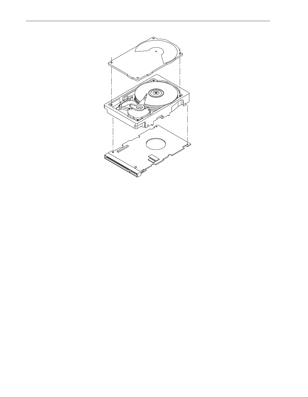
6 Cheetah 4LP Product Manual, Rev. B
Figure 2. Cheetah 4LP family drive
Page 17

Cheetah 4LP Product Manual, Rev. B 7
3.1 Standard features
The Cheetah 4LP famil y has the following stand ard feat ures:
• Integrated SCSI control ler
• Single-ended or differential SCSI drivers and receivers
• 8-bit and 16-bit I/O data bus models availabl e
• Asynchronous and synchronous data transfer protocol
• Firmware downloadable via SCSI interfa ce
• Selectable sector size from 180 to 4,096 bytes/sect or
• Programmable drive capacity
• Programmabl e sector reallocation scheme
• Flawed sector reallocation at format time
• Programmable auto write and read reallocation
• Reallocation of defects on comm and (Po st format )
• Reed-Solomon error correcting code can correct up to 64-bit error
• Sealed head/disc assembly
• No preventative maintenance or adjust men t required
• Dedicated laser textured head landing zone
• Embedded servo data rather than a separate servo data surfa ce
• Self diagnostics performed at power o n
• 1:1 interleave
• Zoned Bit Recording (ZBR)
• Vertical, horizontal, or top-down mounting
• Dynamic spindle brake
• Active IC terminators enabled by jumpers (“N” and “W” models only)
• 442 Kbyte data buffer (2 Mbyte optional)
• Hot Plug compatibility (Sect ion 9.6.4 .3 lists proper host connector need ed) for “WC” and “DC” model drives
• SCAM (SCSI Configured AutoMagically) plug-n-play level 1 compliant as shipped. Level 2 is a factory
installed option.
3.2 Media characteristics
The media used on the drive has a diameter of approximately 3.5 inches (86 mm). The aluminum substrate is
coated with a thin film magnet ic m ateri al, overcoate d with a propriet ary prot ective layer f or improved durability
and environmental protectio n.
3.3 Performa nce
• Supports industry standard Fast-20 SC SI inte rface (also called “Ult ra SCS I ”)
• Programmable multi-segmentable cache buffer
• 10,033 RPM spindle. Average latency = 2.99 ms
• Command queuing of up to 64 commands
• Background processing of queue
• Supports start and stop commands (spindle stops spinnin g )
3.4 Reliability
• 1,000,000 hour MT BF
• LSI circuitry
• Balanced low mass rotary voice coil actuator
• Incorporates industry -standard Self-Mo nito ring, Analysis and Reporting Technology (S.M.A.R.T.)
• Incorporates Seek To Improve Rel iabil ity algori thm (STIR)
• 5-year warranty
• Dithering
Page 18

8 Cheetah 4LP Product Manual, Rev. B
3.5 Unformatted and formatted cap aci ties
Formatted ca pacity depends on the number of spare reallocati on sectors reserved and the number o f bytes
per sector. T he followin g table shows the standard OEM model capaci ties:
Formatted [1]
Data Block Size
512 Byte/Sector Unformatted
4.550 GB [2] 5.591 GB
Notes.
[1] Sector size selecta ble at format time. Users having the n ecessary equipment may m odify the da ta block
size before issuing a format command and obtain different fo rmatted capacities than those list ed. User
available capacity depends on spare reallocati on scheme selected. S ee Mo de Select Com ma nd and Fo rmat Command in the
SCSI Interface Product Manual
, P/N 77738479.
[2] Formatted with a regional sparing scheme. Each region contains 12 cylinders. Each region has 108 spare
sectors.
3.6 Program m ab le dr ive c ap aci t y
Using the Mode Select comman d, the drive can change its capacity to something less than maxim um. See
Table 5.2.1-13 in the
SCSI Interface Product Manual
, P/N 77738479, Rev. G or later. Re fer to the Parameter
list block descriptor, number of blocks field. A value of zero in the number of blocks field indicates that the drive
cannot change the capacity it is currently formatted to have. A number in the number of blocks field that is less
than the maximum number of LBAs changes the total drive capacity to the value in the block descriptor number
of blocks field. A value greater than the maximum number of LBAs is rounded down to the maximum capacity.
3.7 Factory installed accesso rie s
OEM standard drives are shipped with the
Cheetah 4LP Installat ion Guide
, P/N 83329110 (unless otherwise
specified). The f actory also shi ps with the drive a small bag of the two jump er plug types used for the J5, J6,
and J2 option select jumper headers.
3.8 Options (factory instal led )
All customer requested opt ions are incorporated during production o r packaged at the manufacturing facilit y
before shipping. Some of the options availabl e are (not an exhausti ve list of possible options):
• Other capacities can be ordered depending on sparing scheme and sector size requested.
• Black plastic front panel. Other panel colors may be special-ordered. Panel has a green, rectangular LED
drive activity indicator lens. The indicator glows when the drive is selected.
• Single-unit shipping pack. The drive is normally shipped in bulk packaging t o provide maximum protection
against transit damage. Units shipped individually require additional protection as provided by the single unit
shipping pack. Users planning single unit distribution should specif y this opt ion.
• The
Cheetah 4LP Installation Guide
, P/N 83329110 is usually included with each standard OEM drive
shipped, but extra copies may be ordered.
• 2 Mbyte cache memory option. Standard cache memory is 442 Kbytes.
• Level 2 SCAM compliance.
3.9 Accessories (user installe d)
The following accessories are available. All accessories may be installed in the field.
• Front panel kit (with green rectangular LE D lens), P/N 734971 51
• Single-unit shipping pack
Cheetah 4LP Installat ion Gu ide
•
, P/N 83329110
Page 19

Cheetah 4LP Product Manual, Rev. B 9
4.0 Performance characteristics
4.1 Internal drive characteristic s (transp arent to user )
Drive capacity 5,591 Gbyte (unformatted) (rounded-off values)
Read/write heads 8
Bytes/track 115,078 Bytes (average) (rounded-off values)
Bytes/surface 751.0 Mbytes (unformatted) (rounded-off values)
Tracks/surface (total) 6,526 Tracks (user accessible)
Tracks/inch 6,932 TPI
Bits/inch (minim um ) 94,001 BPI
Bits/inch (maximum) 135,401 BPI
Internal data rate 122-177 Mbits/sec (variable with zone)
Disc rotational speed 10,033 ±0.5% r/min
Average rotational lat ency 2.99 msec
4.2 SCSI performance charac teristics (vis ible to user)*
The values given in Secti on 4.2.1 apply to all models of the Cheetah 4L P family unless otherwise specified.
Refer to Section 9.10 and to the
4.2.1 Access time [6]
SCSI Interface Product Ma nual,
P/N 77738479 for additional timing detail s.
Including controller overhead
(without disconnect) [2] [3]
Read Write
msec
Average (typical) [2] 7.7 8.7
Single track (typical) [2] 0.98 1.24
Full stroke (typical) [2] 18.2 19.2
4.2.2 Format command executio n time (minutes) [ 1]
ST34501
Maximum (with verify ) < 1 hours
Maximum (no verify) < 0.6 hour
4.2.3 Generalized performance characteristics
Minimum sector interlea ve 1 to 1
Data buffer transfer rate to/from disc media (one 512-byte sector)—variable with zone/cylinder:
Minimum [3] 122 Mbits/sec
Maximum [3] 177 Mbits/sec
Data buffer transfer rate to/from disc media (< 1 track):
Minimum [3] TBD Mbytes/sec divided by (interleave factor)
Average [3 ] TBD M byt es/sec divided by (interleave factor)
Maximum [3] TBD M byt es/sec divided by (interleave factor)
*[ ] All notes for Section 4.2 are listed at end of Section 4.2. 3.
Page 20

10 Cheetah 4LP Product Manual, Rev. B
SCSI interface data transfer rate (asynchronous) [4]:
Maximum instantane ous (16 bit wide) 10.0 Mbytes/sec [5]
Maximum instantane ous (8 bit wide) 5.0 Mbytes/sec [5]
Synchronous transfer rate for SCSI Fast-20 (Ultra SCSI):
8 bit data bus (N model) 2.5 to 20 Mbytes/sec
16 bit data bus (W/WC/WD/DC models) 5.0 to 40 Mbytes/sec
Sect or Si zes
Default
Variabl e
Read/write consecutive sectors on a track Yes
Flaw reallocation perform ance impact :
For flaws reallocated at format time Negligible
For flaws reallocated using the spare sectors per cylinder reallocation scheme 5.98 msec (minimum)
Overhead time for head switch (512-byte sectors) in sequential mode 0.798 msec
Overhead time for one track region switch in sequential mode 1.064 msec (typical)
Average rotational latency 2.99 msec
512-byte user data blocks
180 to 4,096 bytes per sector. In even number of bytes per sector. If n (number of bytes
per sector) is odd, then n–1 will be used.
17.94 msec (maximum )
Notes for Section 4.2.
[1] Execution time measured from receipt of the last Byte of the Command Descriptor B lock (CDB) to the
request for a status byte transfer to the initiator (excluding connect/discon nect).
[2] Typical access times are measured under nominal conditions of temperature, voltage, and horizontal ori-
entation as measured on a representative samp le of drives.
[3] Assumes no errors and no sector has been relocated.
[4] Rate measured from the start of the first sector transfer to or from the host.
[5] Assumes system abi lity to support th e rates listed and no cable loss.
[6] Access time = controller overhead + average seek time
Access to data = controller overhead + average seek time + latency time
4.3 Start/stop time
After DC power at nominal voltage has been applied, the drive becomes ready within 30 seconds if the Motor
Start Option is disabled (i.e., the motor starts as soo n as the power has been applied). If a recoverable error
condition is detected during the start sequence, th e drive executes a recovery procedure which may cause the
time to become ready to exceed 30 seconds. During spin up to ready time the drive responds to some commands over the SCSI interface. Stop time is less than 30 seconds from removal of DC power.
If the Motor Start Opt ion is enabled, the int ernal con troller ac cepts the comm ands listed in the
Product Manu al
been received the drive becomes ready for normal operations within 30 seconds typically (excluding an error
recovery procedure). The Motor Start comm and can also be used to command the drive to stop the spindle
(see the
SCSI Interface Product Manual
less than 3 seconds after DC p ower has been applied. Af ter the Motor St art command has
, P/N 77738479).
SCSI Int erf ac e
There is no power control switch on the drive.
4.4 Prefetch/multi-se gmen ted cach e contro l
The drive provides prefetch (read look-ahead) and multi-segmented cache control algorithms that in many
cases can enhance system performance. “Cache” as used herein refers to the drive buffer storage space when
it is used in “cache” operations. To select prefetch and cache features the host sends t he Mode Sele ct command with the pro per values in the appli cable byt es in Mode Page 08h (see th e
SCSI Interface Prod uct Man-
Page 21

Cheetah 4LP Product Manual, Rev. B 11
ual
, P/N 77738479. Prefetch and cache operation are indepe ndent features from the standpoint that each is
enabled and disabled independent ly via the M ode S el ect comm and. However, in actual operation the prefetch
feature overlaps cache operation somewhat as is noted in Section 4.5. 1 and 4.5.2.
All default cache and prefetch Mode parameter values (Mode Page 08h) for standard OEM versions of this
drive family are given in Table 9.
4.5 Cache operation
In general, 442 Kbytes of the 512 K bytes of physical buffer space in the drive (1,850 Kbytes of the 2. 0 megabytes on units with this option) can be used as storage space for cache operations. The buffer can be divided
into logical segment s (Mode Select Page 08h , byte 13) from which data is read and to which data i s written.
The drive maintains a table of logi cal block disk medium ad dresses of the data stored in each segment of the
buffer. If cache operation is enabled (RCD bit = 0 in Mode Page 08h, byte 2, bit 0. See the
Product Manual,
(if it is there), before any disc ac cess is initiated. If cache operati on is not enabled, t he buffer (still segmente d
with required number of segments) is still used, but only as circular buffer segments during disc med ium read
operations (disregarding Prefet ch operation for th e moment). Tha t is, the drive does not check in the buffer
segments for the requested read dat a, but goes directl y to the mediu m to retrieve it. The retrieved data m erely
passes through some buffer segment on the way to the host. On a cache “miss,” all data transfers to the host
are in accordance with “buffer-full” ratio rules. On a cache “hit” the drive ignores the “buffer-full” ratio rules. See
explanations associated with Mode page 02h (disconnect/reconnect control) in the
Manual
.
P/N 77738479), data requested by the host with a Read command is retrieved from the buffer
SCSI Interface Product
SCSI Int erface
The following is a simplified description of a read operation with cache operation enabl ed:
Case A - A Read command is received and the first logical block (LB) is already in cache:
1. Drive transfers to the initiator the first LB requested plus all subsequen t contiguous LB s that are already in
the cache. This data may be in multiple seg men ts.
2. When the requested LB is reached that is not in any cache segment, the drive fetches it and any remaining
requested LBs from the disc and puts them in a segment of the cache. The drive transfers the remaining
requested LBs from the cache to the host in accordance with the disconnect/reconnect sp e cificat ion m entioned above.
3. If the prefetch feature is enabled, refer to Section 4.5.2 for operat ion from this point.
Case B - A Read command requests data, the first LB of which is not in any segment of the cache:
1. The drive fetches the requested LBs f rom the disc and transfers them into a segment , and from there t o
the host in accordance with the disconnect/reconnect specification referred to in Case A.
2. If the prefetch feature is enabled, refer to Section 4.5.2 for operat ion from this point.
Each buffer segm ent is actuall y a sel f-contained circular storage (wra p-around occurs), the length of which is
an integer number of disc medium sectors. The wrap-around capability of the individual segments greatly
enhances the buffer’s overall performance as a cache storage, allowing a wide range of user selectable configurations, which includes their use in the prefetch operation (if enabled), even when cache operation is disabled
(see Section 4.5.2). Th e number of segment s may be selected using the Mo de Select comm and, but the size
can not be directly selected. Size is selected only as a by-product of selecting the segment num ber specification. The size in Kbytes of each segment is not reported by the Mode Sense command page 08h, bytes 14 and
15. These bytes read OxFFFF, regardless of the number of segments sett ing. If a size specification is sent by
the host in a Mode Sel ect command (byte s 14 and 15) no new segme nt size is set up by the drive, a nd if the
“STRICT” bit in Mode page 00h (byte 2, bit 1) is set to one, the drive responds as i t does for any attempt to
change unchangeable parameters ( see the
any integer number of segments from 1 to 16.
SCSI Interf ace Product Manual).
The drive support s operation of
4.5.1 Caching write data
Write caching is a write operat ion b y the drive that ma kes use of a dri ve buffer storage area wh ere the dat a to
be written to the medium is stored in one or more segment s while th e drive perform s the write com man d.
Write caching is enabled along with read caching. For write caching , the same buffer space a nd segm ent atio n
is used as set up for read functions. The buffer segmentation scheme is set up or changed independently, hav-
Page 22

12 Cheetah 4LP Product Manual, Rev. B
ing nothing to do with whether or not read and write caching is enable d or disabled. When a write comma nd is
issued, the cache is first checked to see if any logical blocks that are to be written are already stored in the
cache from a previous read or write comma nd. If there are, the respect ive cache segments are cleared. Th e
new data is cached for subsequent Read commands.
If the number of write data logical blocks exceeds the size of the segment being writ ten into when the end of
the segment is reached, the data is written into the beginning of the same cache segment, overwriting the data
that was written there at the beginning of the operation. However, the drive does not overwrite data that has not
yet been written to the medium .
Table 9 shows Mode default settings fo r the drive.
4.5.2 Prefetch operation
If the Prefetch feat ure is ena bled, data in co ntiguous log ical bl o cks on the disc imme diat ely beyon d that wh ich
was requested by a Read comm and can be ret rieved and stored in the b uffer for immediat e transfer from the
buffer to the host on subsequent Read commands that request those logi cal blocks (this is true even if “cache”
operation is disabled). Though the pref etch operati on uses the buffer as a “cache,” finding the requested dat a
in the buffer is a prefetch “hit,” not a “cache” operation “hit.” Prefetch is enabled using Mode Select page 08h,
byte 12, bit 5 (Disabl e Read Ahead - D RA bit). DRA bit = 0 enabl es prefetch. Since data that is prefetched
replaces data already in some buffer segment(s), the host can limit the amou nt of prefetch data to optimize
system performance. The max prefetch field (bytes 8 and 9) limits t he amount of prefetch. The drive does not
use the prefetch “ceiling” field (bytes 10 and 11).
During a prefetch operation, the drive crosses a cylinder boundary to fetch more data only if the Discontinuity
(DISC) bit is set to one in bit 4 of byte 2 of Mode paramete rs page 08h.
Whenever prefetch (read look-ahea d) is enab led (enabled by DRA = 0), it opera tes un der the cont rol of ARLA
(Adaptive Read Look-Ahead). If the host uses software interleave, ARLA enables prefetch of contiguous
blocks from the disc when it senses that a prefetch “hit” will likely occur, even if two consecutive read operations were not for physically contiguous blocks of data (e.g. “software interleave”). ARLA disables prefetch
when it decides that a prefetch “hit” wi ll not likely occur. If the host is not using software interleave, a nd if two
sequential read operations are not for contiguous blocks of data, ARLA disables prefetch, but as long as
sequential read operations request contiguous blocks of data, ARLA keeps prefetch enabled.
Page 23

Cheetah 4LP Product Manual, Rev. B 13
5.0 Reliability specifications
The following reliabilit y specif ications assume correct host/drive operational interface, including all interface
timings, power supply voltages, environment al requi remen ts and drive mounting constraint s (see Sectio n 8.4).
Seek errors
Less than ten in 10
Read error rates [1]
Unrecovered data Less than 1 sector in 10
Miscorrected data Less than 1 sector in 10
MTBF 1,000,000
Service life 5 years
Preventive maintenance None required
Note.
[1] Error rate specified with automat ic retries and data correction wit h ECC enabled an d all flaws reallocated.
5.1 Error rates
The error rates stated in this specification assume the following:
• The drive is operated per this specifica tion using DC power as defined in this manua l (see Sectio n 6.2).
• The drive has been formatted with the SCSI format commands.
• Errors caused by media defects o r host system fail ures are excluded from error rat e computa tion s. Refer to
Section 3.2, “Media Characteristics.”
8
seeks
14
bits transferred (OEM default settings)
21
bits transferred (OEM default settings)
5.1.1 Environmental in te rferen c e
When evaluating s ystems operation under conditions of Electromag netic In terference (EM I), the perform ance
of the drive within the system is considered acceptable if the drive does not generat e an unrecoverable c on dition.
An unrecoverable error, or unrecoverable condition, is defined as one that:
• Is not detected and corrected by the drive itself;
• Is not capable of being detected from the error or fault status provided through the drive or SCSI interface; or
• Is not capable of being recovered by normal drive or system recovery procedures without operator intervention.
5.1.2 Read errors
Before determinat ion or measurem ent of read error rates:
• The data that is to be used for measurement of read error rates must be verified as being written correctly on
the media.
• All media defect induced errors must be excluded from error rate calculations.
5.1.3 Write errors
Write errors can occur as a result of media defects, environment al interference, or equipmen t m alfunction.
Therefore, write errors are not predictable as a function of the number of bits passed.
If a write error un recove rable occurs because of a n equipment malfunct ion in the drive, the error is classifie d
as a failure affecting MTBF. Unrecoverable write errors are those which cannot be corrected within two
attempts at writing the record with a read verify after each attempt (excluding media defects).
5.1.4 Seek errors
A seek error is defined as a failure of the drive to po sition the heads t o the addressed track. There will be no
more than ten recoverable seek errors in 10
8
physical seek operations. After det ectin g an ini tia l seek error, the
drive automatically perform s an error recovery process. If the error recovery process fails, a seek positioning
error (15h) is reported with a Mediu m error (3h) or Hardwa re error (4h) report ed in the Sense Key. This is an
unrecoverable seek error. Unrecoverable seek errors are classified a s failures for M TBF calculat ions. Ref er to
Section 5.1.1.2 of the
SCSI Interface Product Manual,
P/N 77738479, for Request Sense information.
Page 24

14 Cheetah 4LP Product Manual, Rev. B
5.2 Reliability an d servic e
You can enhance the reli ability of Cheetah 4LP disc drives by ensuring that the drive receives adequate cooling. Section 6.0 provides tem perature m easurements and ot her information t hat may be used to enh ance the
service life of the drive. Section 8.3.1 provides recommended air-flow informat ion.
5.2.1 Mean time between failure
The production disc drive achieves an MTBF of 1,000,000 hours when operated in an environment that
ensures that the case temperatures specifi ed in column 2 of Table 3 are not exceeded (see Section 6.4.1).
Short-term excursions up to the specificat ion limits of the operating environm ent (given in Table 3, column 1)
will not affect MTBF perform ance. Continual or sustained operat ion at case temperatures above the values
shown in Table 3, column 2, may degrade product reliability.
The following expression defines MTBF:
Estimated power-on operating hours in the perio d
MTBF per measurement period =
Number of drive failures in the period
Estimated power-on operation hours means power-up hours per disc drive times the total number of disc
drives in service. Each disc drive will have accumulated at least nine months of operation. Data will b e calculated on a rolling average base for a minimum period of six months.
Drive failure means any stoppage or substandard performa nce caused by drive malfunct ion.
5.2.2 Preventive maintenance
No routine scheduled preventive mainten ance is required.
5.2.3 Service life
The drive has a useful service life of five years. Depot repair o r replacem ent of major parts i s permi tted durin g
the lifetime ( see Sect ion 5.2 .4).
5.2.4 Service philosophy
Special equipment is required to repair the drive HDA. In order to achieve the above service life, repairs must
be performed only at a properly equipped and staffed service and repair facility. Troubleshooting and repair of
PCBs in the field is not recommen ded, because of the extensive diagnostic equipment required for effective
servicing . Also, there are no spare parts available for this drive. Drive warranty is voided if the HDA is opened.
5.2.5 Service tools
No special tools are required for site installation or recomm ende d for site maintenance. Refer to Section 5.2. 4.
The depot repair philosophy of the drive precludes the necessity for special tools. Field repair of the drive is not
practical since there are no user purchasable parts in the drive.
5.2.6 Hot plugging Cheetah 4LP disc dri ves
During power-up and power-down periods, the hot SC SI connect/disconnect capability on Cheet ah 4LP SCSI
disc units will produce no glitches and/or any corruptions on an active SCS I bus.
Note. It is the responsibility of the systems int egrat or to assu re that n o tempe ra ture, ene rgy, voltage hazard,
or ESD potential is presented during the hot connect/disconnect operati on.
1. All I/O processes for the SCSI device being inserted or removed shall be quiescent. All other SCSI devices
on the bus shall have receivers that conform to the SCSI-3 standard.
2. A device being inserted shall make its power grou nd and logic ground connection at least 1 millisecond
prior to the connection of any device connecto r contact to the bus. The ground connect ions shall be maintained during and after the connection of the device to the bus.
3. A device being removed shall maintain its power ground and logic ground prior to, during, and for at least 1
msec after the disconnection of any device connector contact from the bus.
Page 25

Cheetah 4LP Product Manual, Rev. B 15
4. The SCSI device being removed or inserted shall employ transceivers that conform to the requirements for
glitch-free powe r-on/off in th e S C S I-3 standard. Th e SCSI device shall maintain the high -impedance state
at the device connector contacts during a power cycle until the transceiver is enabled.
5. The power to the electronics and mechanics of the device may be simultaneously switched with the bus
contacts if the power distribution system i s able to m aintain adequ ate power stabilit y to ot her d e vi ces during the transition and the grounding requireme nts in items 2 and 3 are met.
6. The SCSI bus termination shall be external to the device being inserted or removed.
7. Connector J2 must be configured so there is no connection between the drive and TRMPW R signal on
SCSI bus. Removing all jumpers will accom plish this.
8. The disc drive m otor must come to a com plete st op prior t o changing the plane of operation. This time is
required to insure data integrity.
Note. Hot-plug drives are not designed for simultaneous power discon nection and ph ysical removal .
5.2.7 S.M.A.R.T.
S.M.A.R.T. is an a cronym for Self-Moni toring Analysis and Re porting Technology. This technology is int ended
to recognize conditions that i ndicate a d rive fail ure a nd i s desi gned to provid e sufficient wa rning of a f ailure to
allow data back-up before an actual failure oc curs.
Note. The firmware will monitor specific attributes for degradation over time but cannot predict instantaneous
drive failures.
Each attribute ha s been sele cted to m oni tor a spe cific set of fa ilure con dit ions in the o perat ing pe rform ance of
the drive, and the thresholds are optimized to minim ize “false” and “fai led” predict ions.
Controlling S.M.A.R.T.
The operating mode of S.M.A.R.T. is controlled by the DEXCPT bit and the PERF bit of the “Informational
Exceptions Control M ode Page” (1Ch). The DE XCPT bi t is used to enable or disab le the S.M. A.R.T. process.
Setting the DEXCPT bit will disable all S.M.A.R .T. functions. When enabled, S.M .A.R.T. will collect on-line data
as the drive perform s n o rmal read/writ e o perat ions. Whe n t he PERF b it is set, t he drive is conside re d to be i n
“On-line Mode Only” and will not perform off-line function s.
The process of measuring off-line attributes and saving data can be forced by the RTZ command. Forcing
S.M.A.R.T. will reset the timer so that the next scheduled inte rrup t will be two hours.
The drive can be interrogated by the host to determine the time remaining before the next scheduled measurement and data logging process will occur. This is accomplished by a log sense command to log page 0x3E.
The purpose is to allow the customer to control when S.M.A.R.T. interruptio ns occur. As described above, forcing S.M.A.R.T by the RTZ comm and will reset the timer.
Performa nce imp a ct
S.M.A.R.T . attribute data will be saved to the disc for the purpose of recreating the events that caused a predictive failure. The drive will measure and save para meters once every two h ours subject t o an idle perio d on the
SCSI bus. The process of measuring off-line attribute dat a and saving data to the disc is uninterruptable and
the maximum delay is summarized below:
Maximum processing delay
On-line only delay Fully enabled delay
DEXCPT = 0, PERF = 1 DEXCPT = 0, PERF = 0
S.M.A.R.T. delay times 50 milliseconds 200 milliseconds
Reporting control
Reporting is controlled in the “Inform ational Ex ceptions Control Page” (1Ch). Subject to the reporting method,
the firmware will issue to the “host” an 01-5D00 sense code. The error code is preserved through bus resets
and power cycles.
Page 26

16 Cheetah 4LP Product Manual, Rev. B
Determining rate
S.M.A.R.T. moni tors the rate at which errors occur and signals a p redicti ve f ailure if the rat e of degraded error
rate increases to an unacceptable le vel. To det ermine rat e, error events are logged and com pared to the number of total operations for a given attribut e. The interval d efines the number o f operations over w hich to me asure the rate. The counter that keeps track of the current number of operations is referred to as the Interval
Counter.
S.M.A.R.T. measures error rate, hence for each attribute the occurrence of an “error” is recorded. A counter
keeps track of the number of errors for the current interval. This counter is referred to as the Failure Count er.
Error rate is simply the number of errors per operation. The algorithm that S.M.A .R.T. uses to record rates of
error is to set thresholds for the number of errors and the interval. If the number of errors exceeds the threshold
before the interval expires, then the error rate is considered to be unacceptable. If the number of errors does
not exceed the threshold before the interval expires, then the error rate is considered to be acceptable. In
either case, the interval and failure count ers are reset and the process starts over.
Predictive failures
S.M.A.R.T. signals predi ctive f ail ures when the drive is pe rform ing unaccept ably for a p eri od of tim e. The firm ware keeps a running count of the number of times the error rate for each attribute is unacceptable. To accomplish this, a counter is incremented whenever the error rate is unacceptable and decremented (no t to exceed
zero) whenever the error rate is acceptable. Should the counter continually be incremented such that it
reaches the predictive threshold, a predictive failure is signaled. This counter is referred to as the Failure History Counter. There is a separate Failure History Counter for each attribut e.
5.2.8 Product warranty
Beginning on the date of shipment to customer and continuing for a period of five years, Seagate warrants that
each product (including components and subassemblies) or spare part that fails to function properly under normal use due to defect in materials on workmanship or due to nonconformance to the applicable specifications
will be repaired or replaced, a t Seagate’s opt ion an d at no charge to custom er, if returned by customer at customer’s exp ense to Seagate’s design ated facility in accordance wi th Seagate’s Warranty Procedure. Seagate
will pay for transporting the repair or replacem ent item to customer. F or more detailed warranty information
refer to the Standard Terms and Conditions of Purchase for Seagate products.
Shippi ng
When transporting or shippi ng a drive, a Seagate appro ved container must be used. Keep your origin al box.
They are easily identified by the Seagate Ap proved Package label. Shipping a drive in a non-approved container voids the drive warranty.
Seagate repair centers m ay refuse receipt of components i mprop erly packaged or o bviously damaged in transit. Contact your Autho rized S eagate Di stribut or to purchase a ddit ional boxes. Se agat e recommen ds shippin g
by an air-ride carrier experienced in handling computer equipment.
Product repair and return inform ati on
Seagate customer service centers are the only facilities authorize d to service Seagate drives. Seagate does
not sanction any third-party repair facilities. Any unautho rized repair or tampering with the factory-seal voids
the warranty.
Page 27

Cheetah 4LP Product Manual, Rev. B 17
6.0 Physical/electrical specifications
This section provides information relating to the physical and electrical characteristics of the Cheetah 4LP
drives.
6.1 AC power requ irements
None.
6.2 DC power requ irements
The voltage and current requirements for a single drive are shown in the following table. Values indicated apply
at the drive power connector. The single ended power requirements includes the internal d isc drive SCS I I/O
termination. The table shows current values in Amperes.
Table 2: DC power requirements
Notes
ST34501N/W/WC
Single-ended
ST34501WD/DC
Differential
Voltage +5 V [8] +12 V +5 V [8] +12 V
Regulation [5] ±5% ±5%[2] ± 5% ±5%[2]
Maximum operating current DC3σ [1] 0. 9 0 0.94 1 .09 0.94
Average idle current DCX
[1] [11] 0. 64 0.73 0.72 0. 7 3
Maximum starting current
(peak DC) DC3σ
(peak AC) AC3σ
[3] [6]
[3]
0.88
—
2.2
3.65
0.89
—
2.2
3.65
Delayed motor start (max) DC3σ [1] [4] 0.81 0.08 0 .72 0.08
Peak operating current
Typical DCX
Maximum D C3σ
Maximum (Pe ak) DC3σ
[1] [7]
[1]
0.85
0.9
1.0
0.89
0.94
1.98
1.05
1.09
—
0.89
0.94
1.98
Track following at
OD DCX
ID DCX
[1]
[1]
0.8
0.78
0.73
0.72
0.89
—
0.73
0.72
Read Track
OD DC3σ
AC3σ
Seeking (typical) DCX
Maximum DC3σ
Maximum (peak) AC3σ
[1] [10] 0.95
1.07
0.84
[1] [9]
[1]
0.88
0.93
0.76
1.0
1.11
1.20
2.02
1.26
2.00
0.89
0.93
1.58
0.76
1.0
1.11
1.20
2.02
[1] Measured with average reading DC amm eter. Instantaneous +12V current peaks will exceed these val-
ues.
[2] A –10% tolerance is permissible during initial start of spindle, and mu st return to ±5% before 10,000 rpm
is reached. The ±5% must be mai ntained after the drive signifies th at its power-up sequence has been
completed and that the drive is able to accept selection by the host initiator.
[3] See +12V current profile in Figure 3.
[4] This condition occurs when the Motor Start Option is enabled and the drive has not yet received a Start
Motor command .
[5] See Section 6.2.1, “Conducted No ise Im munit y.” Specified voltage t olera nce is inclusive of ri pple, noise,
and transient response.
[6] At power-up, the motor current regulator limits the 12 volt current to an average value of less than 2.2
amperes, although inst antaneous peaks may exceed this value. These pe aks should measure 5 msec
duration or less.
[7] Operating condition i s defined as a third-st roke seek at OD a nd Read One track. A comm and is is sued
every (0.048 seconds on Wide and SCA drives).
Page 28

18 Cheetah 4LP Product Manual, Rev. B
[8] No terminator power. See Section 9.9.
[9] Seeking is defined as a third-stroke seek at OD. A command is issued eve ry 20 msec.
[10] Read track is defined as repeat reads of track 15 with a duty cycle of 86% for wide single-ended; 62% for
wide differential.
[11] Track following at track 0.
General Notes from Table 2:
1. Minimum current loadi ng for each supply voltage is not less than 2% of the maxim um operating current
shown.
2. The +5 and +12 volt supplies employ separate ground returns.
3. Where power is provided to multiple drives from a common supply, careful consideration for individual
drive power requirements should be not ed. Where multiple unit s are powered on sim ultane ously, the peak
starting current must be available to each device.
4. Envelope values (A C) are measured wit h a 12-inch pow er cable on a switching po wer supply having out put filters of: 5 volt–6,600µFd ; 12 volt–6,60 0µFd.
6.2.1 Conducted no ise immun ity
Noise is specified as a periodic an d random distribution of frequencies covering a band from DC to 10 mHz.
Maximum allowed noise values given below are peak to peak measurements and apply at the drive power connector.
+5 V = 150 mV pp from 0 to 100 kHz and 100 mV pp from 100 kHz to 10 MHz.
+12 V = 150 mV pp from 0 to 100 kHz and 100 mV pp from 100 kHz to 10 MHz.
6.2.2 Power sequencing
The drive does not require power seque ncing. The drive protects a gainst inadvertent writing during power-up
and down. D aisy-chain operation requires that power b e maintained on the terminate d drive to ensure proper
termination of the peripheral I/O cables. To autom atically delay motor start based on the target ID (SCSI ID)
enable the Delay Mot or Start opt ion and disable t he Enable Motor St art option on t he J2 connector. See Section 8.1 for pin selectio n in form at ion. To delay the m otor unt il the drive recei ves a St art Unit comma nd, enabl e
the Enable Motor Start opt ion on the J2 connecto r.
6.2.3 12 V current profile
Figure 3 identifies the drive +12 V current profile. The current durin g the various times is as shown:
T0 - Po we r is applied to the drive.
T1 - Controller self-tests are performed.
T2 - Spi ndle begi ns to accel erate under current limiting after perform ing drive internal
diagnostics. See N ote 1 of Tabl e 2.
T3 - The spindle is up to speed and the Head-Arm restraint is unlocked.
Note. All times and currents are typical. See Tab le 2 for maximum curren t requirement s.
Page 29

Cheetah 4LP Product Manual, Rev. B 19
Peak AC
4.0
Nominal (average DC) curve
3.0
2.0
+12 Volt Current (A)
1.0
0.0
Min AC
T2
T0 T1 T3
0246810121416
Seconds
Figure 3. Typical Cheetah 4LP family drive +12 V current profile
6.3 Power dissipation
For drives with single-ended interface circuits (“N,” “W,” and “WC” models), typical operating random read
power dissipation is 14.9 watts (51 BTUs per hour) of DC power average at nominal voltages. Typical power
dissipation under idle conditions is 12 watts (41 BTUs per hour).
For drives with differential interface circuits (“WD” an d “DC” models), typical operating rand om read power dissipation is 15.9 wat ts (54 BT Us per hour) of DC p ower average at nomi nal vol tage s. Typical power dissipation
under idle conditions is 12.4 watts (42 BTUs per hour).
6.4 Environmental limits
Temperature and hum idi ty values experienced by the drive must be such that condensati on does not occur on
any drive part. Altitude a nd atmospheric pressure specificat ions are referenced to a standard day at 58.7°F
(14.8°C). Maximum wet bulb temperatu re is 82°F (28°C).
Page 30

20 Cheetah 4LP Product Manual, Rev. B
6.4.1 Temperature
a. Operating
With cooling designed to maintain the case temperatures of T able 3, column 2, the drive meets all specifications over a 41°F to 122°F (5°C to 50° C) drive ambient temperature range wi th a maximum temperature
gradient of 36°F (20°C) per hour. The enclosure for the drive should be designed such that the temperatures at the locations specif ied in Tabl e 3, column 1 are not exceeded. Air flow m ay be needed to achi eve
these temperature values (Section 8.3 and 8.3.1). Operation at case temperatures [4] above these values
may adversely affect the drives ability to meet specifications.
The MTBF specifi cation for the drive is based o n operating at a local ambient temperatu re of 86°F (30°C).
Occasional excursions to drive ambient temperatures of 122°F (50°C) or 41°F (5°C) may occur without
impact to specifi ed M TBF. To a ch ieve the s pe cifie d MTBF, the values of Table 3, colum n 2 must be considered maximum average ope rating case temperatures and the en closure for the drive should be designed
such that those temperat ure values are not exceeded. Air f low may be ne eded to achieve these tem peratures (see Section 8.3. 1). Continual or sustained operatio n at case temperatures a bove these val ues may
degrade MTBF.
To confirm that the required cooling for the Cheetah 4LP electronics and HDA is provided, place the drive in
its final mechanical configuration , perform random write/read operati ons typical of expected normal operation. After the t emperatures stabilize, m easure the case temperatu re of the components listed in Table 3
(see notes [2] and [3]).
To obtain th e maximum temperature for each of the reference compone nts listed (Column 1), 36°F (20°C)
was added to the temperatures of Column 2 . The maxi mum HDA case temperature is 140°F (60° C). O peration of the drive at the maximum case temperature is intended for short time periods only. Continuous
operation at the elevated temperat ures will reduce product reliability. See also Section 8.3, “Cooling.”
Table 3. PCB and HDA temperatures
Column 2
maximum allowable
case [4] temperatures (°C)
to meet MTBF spec. [1]
Reference
Items in
figure 4
Column 1
maximum case [4]
temperatures (°C) operating
(45°C ambient) [2]
HDA [3] 60 45
1 U35 68 48
2U883 63
3 U14 81 61
4 U26 81 61
Note.
[1] Section 8.3.1 de scribes the air-flow pa tterns used whe n generating the 1 million h ours MTBF gui de-
lines in column 2. Air flow was opposite that shown in Section 8.3.1. Local air velocity was 0.92 m/se c
(180 lfpm). Inlet air temperat ure to the drive was 77°F (25°C), pl us 9°F (5°C) temperature rise i n the
test enclosure (86°F/30°C am bien t local to the drive).
[2] The temperatures in Column 1 are calculated and may not reflect actu al operating values. Sufficient
cooling air may be required to ensure that these values are not exceeded.
[3] Measure HDA temp at point labeled “HDA” on Figure 4.
[4] PCB mounted integrate d circuit case .
b. Non-operating
–40° to 158°F (–40° to 70°C) package ambient with a maximum gradient of 36°F (20°C) per hour. This
specification assumes that the drive is packaged in the shipping con tainer designed by Seagate for use
with the drive.
Page 31

Cheetah 4LP Product Manual, Rev. B 21
2
“N” Model Drives
14
2
“DC” Model Drives
1
4
3
4
3
4
3
FAAJ
“WC” Model Drives
1
2
JAAJ
“WD” Model Drives
1
2
3
CAAJ
EAAJ
“W” Model Drives
1
4
2
DAAJ
Figure 4. Locations of PCB components listed in Table 3
3
HDA Temp.
Check Point
1.0"
.5"
Page 32

22 Cheetah 4LP Product Manual, Rev. B
6.4.2 Relative humid ity
The values below assume that no condensation on the drive occurs.
a. Operating
5% to 95% non-condensing relative h umi dit y with a maxim um gradient of 10% per hour.
b. Non-operating
5% to 95% non-condensing relative humidity.
6.4.3 Effective altitude (sea level)
a. Operating
–1,000 to +10,000 feet (–305 to +3,048 meters)
b. Non-operating
–1,000 to +40,000 feet (–305 to +12,210 meters)
6.4.4 Shock and vibration
Shock and vibratio n limits specif ied in this document are mea sure d directly on the drive chassis. If the dri ve is
installed in an enclosure to which the stated shock and/or vibratio n criteria is applied, resonances may occur
internally to the enclosure resulting in drive movement in excess of the stated limits. If this situation is apparent, it may be necessary to modify the enclosure to minimize drive movement.
The limits of shock and vibration defined within thi s document are specified with the drive mounted by any of
the four methods shown in Figure 5, and in accordance with the restrictions of Section 8.4. Orientation of the
side nearest the LED may be up or down.
6.4.4.1 Shock
a. Operating—normal
The drive, as installed for normal operation, will operate error free while subjected to intermittent shock not
exceeding 2 g at a maxim um durat ion of 11 msec (half sinewave). S hock may be applie d in t he X, Y, or Z
axis.
b. Operating—abnormal
Equipment, as inst alled for norma l operation, does not incur physical da mage while subjected t o intermittent shock not exceeding 10 g at a maximum duration of 11 msec (half sinewave). Shock occurring at
abnormal levels may promote degraded operational performance during the abnormal shock period. Specified operational performance will continue when normal operating shock levels resume. Shock may be
applied in the X, Y, or Z axis. Shock is not to be repeated more than two times per second.
c. Non-operating
The limits of non-operati ng shock apply to all cond itions of handling and transport ation. This incl udes both
isolated drives and integrated drive s.
The drive subjected to non-repetitive shock not exceeding 50 g at a maximum duration of 11 msec (half sinewave) does not exhibit device damage or performance degradation. Shock may be appli ed in the X, Y, or
Z axis.
The drive subjected to non-repetitive shock not exceeding 140 g at a maximum duration of 2 msec (half sinewave) does not exhibit device damage or performance degradation. Shock may be appli ed in the X, Y, or
Z axis.
Page 33

Cheetah 4LP Product Manual, Rev. B 23
d. Packaged
Disc drives shipped as loose load (not palletized) general freight will be packaged to withstand drops from
heights as defined in the table below. For additional details refer to Seagate specifications 30190-001
(under 100 lb/45 kg) or 30191-001 (over 100 lb/45 kg).
Package size Packaged/product weight Drop height
<600 cu in (<9,800 cu cm) Any 60 in (1,524 mm )
600-1800 cu in (9,800-19,700 cu cm) 0-20 lb (0-9.1 kg) 48 in (1,219 mm)
>1800 cu in (>19,700 cu cm) 0-20 lb (0-9.1 kg) 42 in (1,067 mm)
>600 cu in (>9,800 cu cm) 20-40 lb (9.1-18.1 kg) 36 in (914 mm)
Z
Y
X
Figure 5. Recommended mounting
X
Z
Y
Page 34

24 Cheetah 4LP Product Manual, Rev. B
6.4.4.2 Vibration
a. Operating—normal
The drive as installed for normal operation, complies with the complete specifi ed performance while subjected to continuous vibration not exceeding
5-350 Hz @ 0.5 g
Vibration may be applied in the X, Y, or Z axis.
b. Operating—abnormal
Equipment as install ed for normal operation, will not incur physical damage while subject to periodic vibration not exceeding:
15 minutes of duration at major resonant frequency
5-350 Hz @ 0.75 g
Vibration occurring at these levels may degrade operational performance during the abnormal vibration
period. Specified operational performance will continue when normal operating vibration levels are
resumed. This assumes system recovery routines are avail able. Abnorm al vibration m ay be applied i n the
X, Y, or Z axis.
c. Non-operating
The limits of non-operat ing vibration apply to all condition s of handling and transportation. This includes
both isolated drives and integrated drives.
The drive will not incur ph ysical damage or degra ded performance as a resul t of continuous vibration not
exceeding:
5-22 Hz @ 0.040 in (1.02 mm) displacement
22-400 Hz @ 2.00 g
Vibration may be applied in the X, Y, or Z axis.
6.4.5 Air cleanliness
The drive is designed to operate in a typical office environment with minimal environmental control.
6.4.6 Acoustics
Sound power during idle mode is 4.6 bels typical when measured to ISO 7779 speci fication .
6.4.7 Electromagnetic susceptibility
See Section 2.1.2.
Page 35

Cheetah 4LP Product Manual, Rev. B 25
6.5 Mechanica l specifi catio ns
The following nomin al dimensio n s are exclusive of the decorative fron t panel accessory. Howe ver, dimensions
of the front panel are shown in f igure below. Refer to Figures 6, 7, and 8 for detailed mounting configuration
dimensions. See Section 8.4, “Drive mounting.”
Height: 1.00 in 25.4 mm
Width: 4.00 in 101.6 mm
Depth: 5. 75 in 146 .05 m m
Weight: 1.3 lb 0.588 k g
N
P
D
.050 in. (1.27mm)
minimum clearance
J2
J6 LED
W [6]
X
A
[3]
C
M
G
L
E
Notes:
[1]
Mounting holes three on each side, 6-32 UNC. Max screw length into
side of drive 0.15 in. (3.81 mm). Screw tightening torque 6.0 in-lb
(.675 NM) max with minimum thread engagement of 0.12 in. (3.05 mm).
[2]
Mounting holes four on bottom, 6-32 UNC. Max screw length into
bottom of drive 0.15 in. (3.81 mm). Screw tightening torque 6.0 in-lb
(.675 NM) max with minimum thread engagement of 0.12 in. (3.05 mm).
B
[5] T
[3]
Power and interface connectors can extend past the “A” dimension
by 0.040 in (1.02mm).
[4]
Decorative front panel.
[5]
HDA mounting hole to centerline of Pin 1 of power connector.
[6]
HDA mounting hole to centerline of Pin 1 of J6. Pin ends on J6 are
nominally flush with end of drive.
[7]
HDA mounting hole to centerline of Pin 1 of J2.
[8]
Dimensions to Pin 1 of each connector are nominal values.
[9]
HDA mounting hole to centerline of LED lens.
Inches Millimeters
5.750
[9]
A
B
C
D
E
F
G
H
J
K
L
M
N
P
H
S
R
S
T
U
V
W
X
4.000
1.000
0.625
4.000
0.250
2.375
3.750
2.370
1.750
0.181
0.340
0.190
0.015
1.100
4.100
0.143
0.260
0.030
0.405
2.265
±
±
+
–
±
±
±
±
±
±
±
±
±
±
max
±
±
[8]
0.010
0.010
0.026
0.010
0.020
0.005
0.005
0.010
0.010
0.010
0.020
0.015
0.015
0.010
0.010
0.010
146.05
101.60
25.40
15.87
101.60
60.32
95.25
60.20
44.45
0.381
27.94
104.14
10.28
57.53
6.35
4.32
8.64
4.83
3.63
6.60
0.76
±
±
±
±
±
±
±
±
±
±
±
±
±
max
±
±
.25
.25
.38
.50
.13
.13
.25
.25
.25
.50
.38
.38
.25
.25
.25
[8]
K
[1]
R
F
[2]
U [7]
[7] V
J
[4]
Figure 6. Mounting configuration dimensions for model “N”
Page 36

26 Cheetah 4LP Product Manual, Rev. B
N
P
D
.050 in. (1.27mm)
minimum clearance
B
J2
J6 LED
W [6]
X
H
[9]
A
[3]
C
M
G
E
E
[5] T
Notes:
[1]
Mounting holes three on each side, 6-32 UNC. Max screw length into
side of drive 0.15 in. (3.81 mm). Screw tightening torque 6.0 in-lb
(.675 NM) max with minimum thread engagement of 0.12 in. (3.05 mm).
[2]
Mounting holes four on bottom, 6-32 UNC. Max screw length into
bottom of drive 0.15 in. (3.81 mm). Screw tightening torque 6.0 in-lb
(.675 NM) max with minimum thread engagement of 0.12 in. (3.05 mm).
[3]
Power and interface connections can extend past the “A” dimension
by 0.040 in. (1.02 mm).
[4]
Decorative front panel.
[5]
HDA side to centerline of Pin 1 of power connector.
[6]
HDA mounting hole to centerline of Pin 1 of J6. Pin ends on J6 are
nominally flush with end of drive.
[7]
HDA mounting hole to centerline of Pin 1 of J2.
[8]
Dimensions to Pin 1 of each connector are nominal values.
[9]
HDA mounting hole to centerline of LED lens.
L
Inches Millimeters
5.750
A
B
C
D
E
F
G
H
J
K
L
M
N
P
R
S
T
U
V
S
W
X
4.000
1.000
0.625
4.000
0.250
2.375
3.750
2.370
1.750
0.181
0.340
0.190
0.015
1.100
4.100
0.265
0.260
0.030
0.405
2.265
±
±
+
–
±
±
±
±
±
±
±
±
±
±
max
±
±
[8]
0.010
0.010
0.026
0.010
0.020
0.005
0.005
0.010
0.010
0.010
0.020
0.015
0.015
0.010
0.010
0.010
146.05
101.60
25.40
15.87
101.60
60.32
95.25
60.20
44.45
0.381
27.94
104.14
6.731
10.28
57.53
6.35
4.32
8.64
4.83
6.60
0.76
±
±
±
±
±
±
±
±
±
±
±
±
±
max
±
±
.25
.25
.25
.50
.13
.13
.25
.25
.25
.50
.38
.38
.25
.25
.25
[8]
K
[1]
R
F
[2]
U [7]
[7] V
J
[4]
Figure 7. Mounting configuration dimensions for models “W” and “WD”
Page 37

Cheetah 4LP Product Manual, Rev. B 27
N
P
D
.050 in. (1.27mm)
minimum clearance
J2
A
[3]
C
M
G
E
L
Notes:
Mounting holes three on each side, 6-32 UNC. Max screw length into
[1]
side of drive 0.15 in. (3.81 mm). Screw tightening torque 6.0 in-lb
(.675 NM) max with minimum thread engagement of 0.12 in. (3.05 mm).
Mounting holes four on bottom, 6-32 UNC. Max screw length into
[2]
bottom of drive 0.15 in. (3.81 mm). Screw tightening torque 6.0 in-lb
(.675 NM) max with minimum thread engagement of 0.12 in. (3.05 mm).
Interface connector is flush with the end of drive within ±0.020 in.
[3]
(.5 mm). The interface connector location may extend beyond HDA
dimension “A” by 0.020 in. (.5 mm).
B
[5]
AA
Decorative front panel (optional).
[4]
Connector J1 is centered (side to side) on drive within ±0.020 in.
[5]
(.508 mm).
Dimension “U” is from bottom rear drive mounting holes center(s) to
[6]
the face of the connector at the center of the drive.
Dimensions “T” and “U” are unique requirements for SCA drives only,
[7]
required for conformance with latest SFF Spec #8337.
Maximum connector non-perpendicularity to side planes pointed to by AA.
[8]
HDA mounting hole to centerline of Pin 1 of J6. Pin ends on J6 are
[9]
nominally flush with end of drive.
HDA mounting hole to centerline of Pin 1 of J2. Dimensions indicated
[10]
are for reference only.
Dimensions to Pin 1 of each connector are nominal values.
[11]
HDA mounting hole to centerline of LED lens.
[12]
[7] [8]
AAT
[1]
R
U [6] [7]
V [10]
[10] W
K
F
[2]
A
5.750
B
4.000
C
1.000
[8]
[7]
D
0.625
E
4.000
F
0.250
G
2.375
H
3.750
J
2.370
K
1.750
L
0.181
M
0.275
N
0.190
P
0.015
R
1.100
S
4.100
T
0.150
U
1.620
V
0.260
W
0.030
X
0.405
Y
2.265
J
J6 LED
[4]
X [9]
[12]
Y
H
S
0.010
±
0.010
±
0.026
+
0.010
–
0.020
±
0.005
±
0.005
±
0.010
±
0.010
±
0.010
±
0.020
±
0.015
±
0.015
±
0.010
±
max
0.010
±
0.010
±
0.020
±
[11] [11]
Figure 8. Mounting configuration dimensions for models “WC” and “DC”
MillimetersInches
146.05
101.60
25.40
15.87
101.60
6.35
60.32
95.25
60.20
44.45
4.32
7.00
4.83
0.381
27.94
104.14
0.38
41.15
6.60
0.76
10.28
57.53
±
±
±
±
±
±
±
±
±
±
±
±
±
max
±
±
±
.25
.25
.38
.50
.13
.13
.25
.25
.25
.50
.38
.38
.25
.25
.25
.50
Page 38

Page 39

Cheetah 4LP Product Manual, Rev. B 29
7.0 Defect and error management
The drive, as delivered, complies with this specification. The read error rate and specified storage capacity are
not dependent upon use of defect managem ent routines by the host (initiato r).
Defect and error managem ent in the SCSI system involves the drive internal defect /error management and
SCSI systems error considerations (errors in co mmunicat ion s betwe en Initiator and t he drive). Tool s for use in
designing a defect/error man agem ent plan are briefly out lin ed in this sectio n, with ref erences to other secti on s
where further details are given.
7.1 Drive internal defects
During the initial drive format operation at the factor y, media defects are identi fied, tagged as being unusable,
and their locations recorded on the drive primary defects list (ref erred to as the “P” list and also as the EFT
defect list). At factory format time, these known defects are also reallocated , that is, reas signed to a new place
on the medium and the locat ion listed in the de fects reallocat ion table. The “P” list is not altered after fa ctory
formatting. Locations of defects found and reallocated during error recovery procedures after drive shipment
are listed in the “G” list (def ects growth list). Th e “P” and “G” lists may be refere nced by the i nitiat or using the
Read Defect Data command (see Section 5.2.1.2 in the
77738479).
7.2 Drive error recovery procedures
Whenever an error occurs during drive operation, the drive, if programm ed to do so, perf orms error recovery
procedures to attempt to recover the data. The error recovery procedures used depend on the options previously set up in the error recovery parameters mod e page. Error recovery and defect management may involv e
the use of several SCSI commands, the details of which are described in the
The drive implements selectable error recovery time limits such as are required in video applications. For additional informati on on this, refer to Table 5.2.1-22 in the
Mode Select/Mode Sense Error Recovery parameters.
SCSI Interface Product Manual,
SCSI Interface Product Ma nual.
SCSI Interface Product Manua l
which describes the
part number
The error recovery scheme supported by the drive provides a means to control the total error recovery time for
the entire command in addition to controlling the recovery level for a single LBA. The total amount of time spent
in error recovery for a command can be limited via the Recovery Time Li mit bytes in the Error Recovery Mode
Page. The tota l amount of time spent in error recovery for a singl e LBA can be limited via the Re ad Retry
Count or Write Retry Count bytes in the Error Recovery Mode Page.
The drive firmware error recovery algorithms consist of 16 levels for read recoveries and 12 levels for writes.
Each level may consist of multipl e steps, where a step is defined as a recovery functi on involving a singl e reread or re-write attempt. The maximum level used by the drive in LBA recovery is determined by the Read and
Write Retry Counts.
Table 4 equates the Read and Write Retry Count with the maxim um possib le recovery time for read and write
recovery of individual LBAs. The times given do not include time taken to perform reallocations, if reallocations
are performed. Reallocations are perform ed when t he ARRE bit (for reads) or AWRE bit (for writes) is one, the
RC bit is zero, and the R ecove ry Time Limit for the co mmand has not yet been m et. Time needed to perform
reallocation is not counted against t he Reco very Time Limit.
When the RC bit is one, reallocations are disabled even if the ARRE or AWRE bits are one. The drive will still
perform data recovery actions within the limits defined by the Read Retry Count, Write Retry Count, and
Recovery Time Limit parameters. However, the drive does not report any unrecovered errors.
Page 40

30 Cheetah 4LP Product Manual, Rev. B
Table 4: Read and write retry count maximum recovery times
Read retry
count [1]
030 030
148 148
266 266
390 3102
4 132 4 126
5 156 5 132
6 192 6 156
7 264 7 192
8 288 8 246
9 324 9 318
10 378 10 678
11 486 11 1537
12 636 12 (default) 2397
13 995
14 1855
15 1714
16 (default) 2822
Maximum recovery time
per LBA (cumulative, msec)
Write retry
count [1]
Maximum recovery time
per LBA (cumulative, msec)
[1] Setting these retry counts to a value below the default setting could result in degradation of the unrecov-
ered error rate below the product specification.
For example, suppose t he read/write recovery page has the RC bit = 0, the read retry count set to 4 , and the
recovery time limit set to 450. A 4-block read command can take up to 132 msec recovery time for each block
and a maximum of 450 msec recovery for all 4 blocks. If either of the se limits is reache d and a block has not
yet been recovered, the comman d will end with CHEC K CONDITION st atus and an u nrecoverable read error
will be reported.
7.3 SCSI systems errors
Information on the report ing of operational errors or faults across the interf ace is given in the
Product Manual
. Message P rotocol System is described in the
SCSI Interface Product Manual
SCSI Int erfac e
. Several of the
messages are used in the S CSI systems error management system. The Request Sense comm and returns
information to the host about numerous kinds of errors or faults. Th e Receive Diagnostic Results report s the
results of diagnostic operations performed by the drive.
Status returned by the drive to the initiator is described in the
SCSI Interface Prod uct Manual
. Status reporting
plays a role in the SCS I systems e r ror managem ent and its use i n that respect is described in secti ons where
the various commands are discussed.
Page 41

Cheetah 4LP Product Manual, Rev. B 31
8.0 Installatio n
The first thing to do when installing a drive is to set the drive I D (select) on the SCSI bus and set up certain
operating options. This is usually done by installing small shorting jumpers on the pins of connectors J2 and J6
on the PCB (or J5 on the “W” and “WD” models), or via the drive to host I/O signals on “WC” and “DC” models.
Some users connect cables to J6 or J5 and perform the set-up using remote switches.
If your system is “SCAM” (SCSI Configured Auto Magical ly) compliant, the system assigns the drive ID over
the interface, so there is no need to be concerned about drive ID. Setting the drive ID jumpers doesn’t hurt anything, but is not necessary.
If your system is not “SCAM” compliant you do need to set the drive ID using the ID jumpers.
Configure dr ive options
For option jumper location s and definitions refer to Figures 9, 10, and 11. Drive default mode parameters are
not normally needed for inst allat ion . Refer to Section 9.3.2 f or defaul t mode param eters if they are needed.
• Ensure that the SCSI ID of the drive is not the same as the host adapte r. Most host adapters use SCSI ID 7.
ID 7 is the highest priority on both 8 and 16 bit data buses.
• If multiple devices are on the bus set the drive SCSI ID to one that is not presently used by other devices on
the bus.
• If the drive is the only device on the bus, attach it to the end of the SCSI bus cable. Permanently inst alled
terminators must be enabl ed on the drive for “N” and “W” models using jum per plug TE if term ination is not
provided by the host equipment. On model “WC,” “WD,” and “DC” models, external terminators must be provided by the user, systems integrat or or host equipm ent m anuf acturer.
• If the drive is attached to a bus that contains other devices, and the new drive is not attached to t he end of
the bus, the Terminat or Ena ble jum per (TE) should be removed from the new drive.
Note. For additional information about termin ator requi remen ts, refer to Sections 9.8 and 9.9.
• Set all appropriate option jumpers for desired operation prior to power on. If jumpers are changed after
power has been applied, recycle the drive power to make the new setting s effective.
• Installation instruct ions are provided by host sy stem docume ntat ion or with any additional ly pu rchased drive
installation software. If necessary see Sect ion 10 for Seagat e support services telep hone num bers.
• Do not remove the m anuf actu rer ’ s installed lab els from the drive and do n ot cover wit h addit ional lab els, as
the manufacturer labels contain information required when servicing the product.
Formatting
• It is not necessary to low level format this drive. The drive is shipped from the factory low level formatted in
512-byte sectors.
• Reformat the drive if a different spare sector allocatio n scheme is selected.
• High level format the drive involves assigning one or m ore partitions or logical drives to the drive volume.
Follow the instructi ons in the system manuals for the s ystem into which the drive is to be installed.
• Systems that have Windows 95 Opera ting System version 950B (this has FAT 32) or later do not need to
partition the drive.
8.1 Drive ID/option select header
Figures 9, 10, and 11 show views of the drive ID select jumper connectors and the option select jumper connector for all models. Figure 10 shows a rear view of model drives for the purpose of showing J1-auxiliary of
the drive. Both J5 and J6 have pins for selecting drive ID and for connecting the remote LED cable. Only one or
the other should be used, although using both at the same time would not damage the drive. The notes follo wing the figures describe the functi ons of the various jumper positions on the connectors J2, J5, and J6. Suggested part number for the jum pers used on J2 is Mo lex 52747-0211 (Seagate P/N 77679052). A bag with the
two jumper plug types is shipped with the standard OEM drives.
Page 42

32 Cheetah 4LP Product Manual, Rev. B
Jumper Plug
(enlarged to
show detail)
SCSI ID = 0 (default)
SCSI ID = 1
SCSI ID = 2
SCSI ID = 3
SCSI ID = 4
SCSI ID = 5
SCSI ID = 6
SCSI ID = 7
Activity LED
Reserved
Activity LED
Reserved
The shaded pins are shipped
with a cover installed. Do not
install jumpers on these pins.
Retain the cover unless you
install a 20-pin plug.
J2
J6 [4]
Pin 1
End
Pin 1
Enable Terminator (default)
Delay Motor Start
Enable Motor Start
Write Protect
J6
Disable SCSI Parity
Reserved [3]
Term. Power from Drive (default)
Term. Power to SCSI Bus
Term. Power from SCSI Bus (position A)
Term. Power to SCSI Bus and Drive
+5V (anode) [7]
–Active (cathode)
[3]
+5V (anode) [6]
–Active (cathode)
J2 Jumper
(enlarged to
show detail)
J2
M
W
P
E
P
D
Pin 1
SCSI I/O
R
E
S
T
D
E
S
J2
J6
Connector
Drive
Front
DC Power
Connector
Caution:
Do not use J2 jumper plugs on J6.
The internal contacts will be bent
and cannot be reused on J2
without them falling off.
Pin 1
Pin 2
T
T
P
P
2
1
J1
Figure 9. Model “N” option select jumper connectors
Notes for Figures 9, 10, and 11 are in Sect ion 8.1.1 .
Page 43

Cheetah 4LP Product Manual, Rev. B 33
Pin 1
Pin 2
R
T
T
E
P
P
S
2
1
J1
J5
1P2P3P4P
Jumper Plug
J2
(enlarged to
show detail)
Pin 1
End
J6 [4]
Pin 1
SCSI ID = 0 (default)
SCSI ID = 1
SCSI ID = 2
SCSI ID = 3
SCSI ID = 4
SCSI ID = 5
SCSI ID = 6
SCSI ID = 7
SCSI ID = 8
SCSI ID = 9
SCSI ID = 10
SCSI ID = 11
SCSI ID = 12
SCSI ID = 13
SCSI ID = 14
SCSI ID = 15
Reserved
Activity LED
Reserved
The shaded pins are shipped
with a cover installed. Do not
install jumpers on these pins.
Retain the cover unless you
install a 20-pin plug.
Caution:
[3]
+5V (anode) [6]
–Active (cathode)
Do not use J2 jumper plugs on J6. The internal contacts will
be bent and cannot be reused on J2 without them falling off.
“W/WD” Models
Enable Terminator (default)
Delay Motor Start
Enable Motor Start
Write Protect
Disable SCSI Parity
J6
Reserved [3]
“W” Models
Term. Power from Drive (default)
Term. Power to SCSI Bus
Term. Power from SCSI Bus (position A)
Term. Power to SCSI Bus and Drive
“WD” Models
Term. Power to SCSI Bus (default)
Host adapter or other device provides
term. power to external terminator.
J2 Jumper
(enlarged to
show detail)
68 Pin
SCSI I/O Connector
J1
SCSI Address A
SCSI Address A
SCSI Address A
SCSI Address A
No connection
+5V
Fault LED*
Vendor Unique*
[3]
Reserved
Activity LED*
Ground*
These pins are driven low for
*
250 ms after PWR ON or
RESET to allow jumper
selectable SCSI ID as shown
to the right.
Pin 1
Pin 12
J6
Drive
Front
0
1
2
3
J5 [2][4]
J5 Pin 1
J2
T
E
SCSI ID = 0
SCSI ID = 1
SCSI ID = 2
SCSI ID = 3
SCSI ID = 4
SCSI ID = 5
SCSI ID = 6
SCSI ID = 7
SCSI ID = 8
SCSI ID = 9
SCSI ID = 10
SCSI ID = 11
SCSI ID = 12
SCSI ID = 13
SCSI ID = 14
SCSI ID = 15
D
M
W
P
S
E
P
D
Pin 1
J2
SCSI I/O
Connector
DC Power
Connector
Pin 1
J1-DC Power
Figure 10. Cheetah 4LP family drive ID select for models “W” and “WD”
Page 44

34 Cheetah 4LP Product Manual, Rev. B
Jumper Plug
(enlarged to
show detail)
SCSI ID = 0 (default)
SCSI ID = 1
SCSI ID = 2
SCSI ID = 3
SCSI ID = 4
SCSI ID = 5
SCSI ID = 6
SCSI ID = 7
SCSI ID = 8
SCSI ID = 9
SCSI ID = 10
SCSI ID = 11
SCSI ID = 12
SCSI ID = 13
SCSI ID = 14
SCSI ID = 15
Reserved
Activity LED
Reserved
The shaded pins are shipped
with a cover installed. Do not
install jumpers on these pins.
Retain the cover unless you
install a 20-pin plug.
J6
J2
[4]
Pin 1
Pin 1
End
J6
“WC/DC” Models
Delay Motor Start
Enable Motor Start
Write Protect
Disable SCSI Parity
Reserved
J2 Jumper
(enlarged to
show detail)
[3]
+5V (anode) [6]
–Active (cathode)
J2
R
R
W
P
P
D
Pin 1
80 Pin
R
E
E
S
S
E
D
M
S
S
E
J2
J6
Drive
Front
Caution:
SCSI I/O
Connector
Do not use J2 jumper plugs on J6.
The internal contacts will be bent
and cannot be reused on J2
without them falling off.
R
E
S
Pin 1
Pin 2
[5]
[5]
[3]
Figure 11. Model ST34501WC/DC option select jumper connectors
Page 45

Cheetah 4LP Product Manual, Rev. B 35
8.1.1 Notes for Figures 9, 10, and 11.
[1] Notes explaining t he functions of the various jumpers on jumper heade r connectors J2, J5, and J6 a re
given here and in Section 8.1.2. The term “ default ” means as standard OE M units are conf igured with a
jumper on tho se positions when shippe d from factory. “Off” means no jumper is i nstalled; “On” mea ns a
jumper is installed. OFF or ON underlined is facto ry default condit ion .
[2] The PCB on “N,” “WC,” and “DC” model drives does not have connector J5. The J5 connector signals
conform to SFF-8009 Revision 2.0, Unitized Connector for Cabled Drives, signal assignments for auxiliary
connectors. See note [4].
[3] Reserved useage. Do not install any jumpers.
[4] Table 5 summa rize s the configurat ion select ion possibi lities availabl e on the different Cheet ah 4LP mode l
drives.
[5] These signals are also on 80 pin J1. See Table 13d and 13e.
[6] Voltage supplied by the drive. No resistor in series with cat hode.
[7] Voltage supplied b y the drive. Resistor in series with cathode .
Table 5. Dri ve configuration selections summary
Interface
Type Function
Connector
Applicable
FigureJ1 J6 J5 J2
N Drive I D X, Y none 9
N Drive Act ivity LED Y [c] none 9
N Opt ion select none X 9
W, WD Drive ID X, Y X, Y [e] 10 [a]
W, WD Drive Activit y LE D Y [c] Y [c] 10 [a]
W, WD Option select X 10
WC, DC Drive ID Y[f] X, Y none 11 [d]
WC, DC Drive Act ivit y LED Y[b][c] Y [c] none 11 [d]
WC, DC Option select :
Delayed Mtr Start Y[b] none X 11
Enable Mtr Start Y[b] none X 11
Write Protect none X 11
Parity Disable none X 11
(“X” means the function selection can be mad e with jumpers on that connecto r;
(“Y” means the signal is available to host through that connector.)
Notes for Table 5 [ ]:
[a] Use either J6 or J5, but not both.
[b] I/O connector J1 plugs directly into host. No jum per can be installed on J1. The host supplies the logic
state of these function signals causing the selecti on of these functions. S ee pinout Table 13d and 13e.
[c] The host can drive a remotely locat ed Drive Act ivity LE D using si gnal.
[d] Use either J1 or J6, but not both.
[e] The drive reads the ID (asserted l ow) from J5 pins 1, 3, 5 and 7 f or 25 0 ms after p ow er-on or drive re set.
Jumper plugs can be used on J5 pins 1-2, 3-4, 5-6 and 7-8 to set drive ID if desired, but usually a connec-
tor/cable is plugged to J5 to run these signals to the host for remote ID selection.
[f] The host selects drive ID throug h J1.
Page 46

36 Cheetah 4LP Product Manual, Rev. B
8.1.2 Function description
J2 jumper
installation Jumper fun ctio n des cri ptio n
TE (App lies on ly to “N” and “W” models)
On
With the jumper installed, the On-board (non-removable ) terminat or circuits are enabled
(connected to the I/O lines). Default is jumper installed.
Off Terminat or circui ts not enabled (not connected t o I/O lines).
DS ME (Applies to all mod els)
Off
Off Spindle starts immediately after power up - Default sett ing.
Off On Drive spindle does not start until Start Unit command received from host.
On Off Spindle startup is delayed by SCSI ID times 12 seconds after power is applied, i.e., drive 0
spindle starts immediately when DC power connected, drive 1 starts after 12 second delay,
drive 2 starts after 24 second delay, etc.
On On Drive spindle starts when Start Unit command received from host. Delayed start featu re is
overridden and does not apply when ME jumper is installed.
WP (Applies to all models)
On Entire drive is write protected.
Off
Drive is not write protected. Default is no WP jumper installed .
PD (Applies to all models)
On Parity checking and parity error reporting by the drive is disabled.
Off
Drive checks for parity and reports result of parity checking to host.
Default is PD jumper not install ed.
RES (Applies to all models)
Off
Reserved jumper position. Defaul t is no jumper install ed.
TP2 TP1 (Does not apply to “WC” or “DC” models)
Off Off No terminator power is connected to drive terminators or SCSI bus I/O cable*.
On
Off Drive suppli e s its own terminator power onl y. Jumper on this position is factory default.
Off On Drive supplies power to SCSI bus I/O cable*; none to internal terminators. When drives have
differential I/O circuit s, a jumper on the TP1 position may be needed to power external terminators (see system documen tation ). The “WD” drives have differential I/O circuits which
have no terminator circuits on the drive .
On On Drive supplies terminator power to itself (inte rn al co nnecti on) a nd to S CSI bus I/O cab le*.
This is a legal jumper setting.
TP1 an d TP 2
“Position A” (Applies on ly to “N,” “W,” and “WD” models)
On This horizontally positioned jum per across the two TP positions furt hest fro m the PCB edge,
connects terminator power from SCSI bus I/O Termpower cable* to the drive’s internal terminators (for single-ended I/O only).
Off See above explanations for TP jumpers.
*See Figure 10 for pins used for Termpower.
Page 47

Cheetah 4LP Product Manual, Rev. B 37
8.2 Drive orientation
The balanced rotary arm actuator design of the drive allows it to be mounted in any orientation. All drive performance characterization, however, has been done with the drive in h orizont al (discs level) and vertical (drive on
its side) orientations, and these are the two preferred mount ing orient at ions.
8.3 Cooling
Cabinet cooling must be designed by the customer so that the a mbient te mperature immediate ly surrounding
the drive will not exceed t emperature conditio ns specified in Section 6 .4.1, “Temperat ure.” Specific consideration should be given to make sure adequate air circulation is present around the printed circuit board (PCB) to
meet the requirement s of Section 6.4 .1, “Te mpe ra ture. ”
8.3.1 Air flow
The rack, cabinet, or drawer environ men t for the Cheetah 4LP d rive m ust p ro vide he at re moval from the electronics and head and disc assembly (HDA). You should confirm that adequat e heat removal is provided using
the temperature measurement guidel ines de scribed in Section 6. 4.1.
Forced air flow may be required to keep temperatures at or below the specified case temperatures of Table 3,
Column 2, in which case the drive should be oriented, or air flow directed, so that the least am ount of air flow
resistance is created while providing air flow to the electronics and HDA. Also, the shortest possible path
between the air inlet and exit should be chosen to minimize the travel length of air heated by the drive and
other heat sources within the rack, cabinet, or drawer environment.
If forced air is dete rmin ed to be n ecessary, po ssible air-flow patt erns are sho wn in Figu re 12. The air-flow pat terns are created by one or more fans, either forcing or drawing air as shown in the illustrations. Conduction,
convection, or other forced a ir-flow patterns are a cceptable as long as the temperat ure measurement guidelines of Section 6.4.1 are met.
Above unit
Note. Air flows in the direction shown (back to front)
or in reverse direction (front to back)
Under unit
Note. Air flows in the direction shown or
in reverse direction (side to side)
Figure 12. Air flow (suggested)
Above unit
Under unit
Page 48

38 Cheetah 4LP Product Manual, Rev. B
8.4 Drive mounting
When mounting t he d rive using the bottom holes (x-y plan e in Figu re 5) care must be taken to ensure that the
drive is not physically distorted due to a stiff non -flat mount ing surface. The following equation and paragraph define the allowable moun ting surface stiffne ss:
K * X = F <
15 lb. = 67N
where ‘k’ represents the mounting surface stiffness (units of lb/in or N/mm), and ‘x’ represents the out-of-plane
mounting surface disto rtion (units of inches or millimeters). The out-of-plan e distortion (‘x’) is determined by
defining a plane wit h three of the four mount ing points fixed and evaluating the o ut-of-plane deflection of the
fourth mounting point when a known force is applied to the fourth point.
Note. Before mounting the drive in any kind of 3.5-inch to 5.25-inch adapter frame, verify with Seagate Tech-
nology that the drive can meet the sho ck and vibration specifica tions given herein whi le mounted in
such an adapter frame. Adapter frames that are available may not have a mechanical structure capa ble of mountin g the drive so t hat it can meet the shock and vibrat ion spe cifications list ed in this m anual.
8.5 Grounding
Signal ground (PCB) and HDA ground are connected togeth er in the drive and cannot be separated by the
user. The equipment in which the drive is mounted is connected directly to the HDA and PCB with no electrically isolating shock mounts. If it is desired for the system chassis to not be connected to the HDA/PCB
ground, the systems integrat or or user must provide a nonconductive ( electrical ly isolating) method o f mounting the drive in the host equipment.
Increased radiated emissions may result if you do not provide the maxim um surface area ground connection
between system ground and drive ground. T his is the system designer ’s and integrator’s responsibility.
Page 49

Cheetah 4LP Product Manual, Rev. B 39
9.0 Interface requirements
This section describes Cheetah 4LP interface requirements.
9.1 General description
This sect ion partially describes the interface requirem ent s as im plem ented on the drives. The major p ortion
of the interface re quirements / implemen tation is d escribed in the Seagat e
P/N 77738479. This section has tables that give the Cheetah 4LP family drive's version of the SCSI implemen-
tation described in the
SCSI Interface Product Manual
.
9.2 SCSI interface messages sup po rted
Table 6 lists the messages supported by the SC SI-2 and SCSI -3 modes of the Cheetah 4LP family drives.
Table 6. SCSI m essages supported by Cheetah 4LP family drives
Message Name Message Code
Abort 06h Y
Abort-tag 0Dh Y
Bus device reset 0Ch Y
Clear queue 0Eh Y
Command com plet e 00 h Y
Continue I/O process 12h Y
Disconnect 04h Y
Extended messag e s 01h[1] Y
Identify 80h-FFh Y
Ignore wide residue (two bytes) 23h Y
Initiate recovery 0Fh N
Initiator detect ed error 0 5h Y
Linked command complete 0Ah Y
Linked command com plet e with flag 0Bh Y
Message parity error 09h Y
Message reject 07h Y
Modify data pointer [1] N
No operation 08h Y
Queue tag messages (two bytes)
Head of queue tag 21h Y
Ordered queue tag 22h Y
Simple queue tag 20h Y
Release recovery 10h N
Restore pointers 03h Y
Save data pointer 02h Y
Synchronous data transfer req. [1] Y
Target transfer disable 13h Y
Terminate I/O process 11h N
Wide data transfer request [1] [2] Y
SCSI Interfac e Product Manual
Supported by
SCSI-2/3
,
Notes.
[1] Extended messages (see the
SCSI Interface Product Manual,
P/N 77738479).
Page 50

40 Cheetah 4LP Product Manual, Rev. B
[2] Not applicable to “N” models.
9.3 SCSI interface comman ds supp orted
Table 7 following l ists the SCSI int erface commands that are supported in the S CSI-2, and SCS I-3 modes of
the drive. Cheetah 4LP family drives can be chan ged back and forth between SCSI-1 and SCSI-2/SCSI-3
modes using the Cha nge Definition command. OEM standard drives are shipped set to operat e in SCSI-2/
SCSI-3 mode.
Table 7: Commands supported by Cheetah 4LP family drive
Command
Command name
code
Change definit ion 40h Y
Compare 39h N
Copy 18h N
Copy and verify 3Ah N
Format unit [1] 04h Y
Block Format N
Bytes from inde x Y
Physical sector format Y
DPRY bit supported Y
DCRT bit supported Y
STPF bit supported Y
IP bit supported Y
DSP bit supported Y
IMMED bit supported Y
VS (vendor specific) N
Inquiry 12h Y
Date code page (C1h) Y
Device Behavior page (C3h) Y
Firmware numbers page (C0h) Y
Implemente d operati ng def page (81h) Y
Jumper settings page (C2h) Y
Supported Vital pro duct dat a page (00h) Y
Unit serial number page (80h) Y
Lock-unlock cache 36h N
Log select 4Ch Y
DU bit N
DS bit Y
TSD bit Y
ETC bit N
TMC bit N
LP bit N
Log sense 4Dh Y
Cache statistics page (37h) Y
Non-medium error page (06h) N
Pages supported list (00h) Y
Power-on time page (3Eh) Y
Read error counte r page (03h) Y
S.M.A.R.T. stat us log page (2Fh ) N
S.M.A.R.T. at titude log page (30h) N
Verify error counter page (05h) Y
Write error counter page (02h) Y
Supported by
SCSI-2/3
Page 51

Cheetah 4LP Product Manual, Rev. B 41
Table 7: Commands supported by Cheetah 4LP family drive (Continued)
Command name
Command
code
Supported by
SCSI-2/3
Mode select (same pages as Mode Sense command) 15h Y [2]
Mode select (10) 55h Y
Mode sense 1Ah Y [2]
Caching parameters page (08h) Y
Control mode page (0Ah ) Y
Disconnect/reconnect (02h) Y
Error recovery page (01h) Y
Format page (03h) Y
Information exceptions control page (1Ch) Y
Notch and Partition P age (0C h) N
Power condition page (1A h) Y
Rigid disc drive geometry page (04h) Y
Unit attention page (00h) Y
Verify error recovery page (07h) Y
Xor Control page (10h) Y
Mode sense (10) 5Ah Y
Prefetch 34h N
Read 08h Y
Read buffer (modes 0, 2, 3 supported) 3 Ch Y
Read capacity 25h Y
Read de fect data 37h Y
Read extended 28h Y
DPO bit supported Y
FUA bit supported Y
Read long 3Eh Y
Reassign blocks 07h Y
Rebuild 81h N
Receive diagnostic results 1Ch Y
Supported diagnostics pages (0h) Y
Translate page (40h) Y
Regenerate 82h N
Release 17h Y
Release (10) 57h Y
Request sense 03h Y
Actual retry count bytes Y
Deferred error supported Y
Extended sense Y
Field pointer bytes Y
Reserve 16h Y
3rd party reserve Y
Extent reservation N
Reserve (10) 56h Y
3rd part reserve Y
Extent reservation N
Rezero unit 01h Y
Search data equal 31h N
Search data high 30h N
Page 52

42 Cheetah 4LP Product Manual, Rev. B
Table 7: Commands supported by Cheetah 4LP family drive (Continued)
Command
Command name
code
Search data low 32h N
Seek 0Bh Y
Seek extended 2Bh Y
Send diagnostic s 1Dh Y
Supported diagnostics pages (00h ) Y
Translate page (40h) Y
Set limits 33h N
Start unit/stop unit (spindle ceases rot ating) ( 1Ch ) 1Bh Y
Synchronize cache 35h Y
Test unit ready 00h Y
Verify 2Fh Y
DPO bit supported Y
BYTCHK bit supported Y
Write 0Ah Y
Write and verify 2Eh Y
DPO bit supported Y
BYTCHK bit supported Y
Write buffer (modes 0, 2, supported) 3Bh Y
Firmware download option (modes 5, 7 supported) [3] Y
Write extended 2Ah Y
DPO bit supported Y
FUA bit support Y
Write long 3F h Y
Write same 41h Y
XDRead 52h Y
XDWrite 50h Y
XDWrite extended 80h N
XPWrite 51h Y
Supported by
SCSI-2/3
[1] The drive can format to any even number of bytes per sector from 180 to 4,096
[2] Table 9 shows how individual bits are set that are changeable by the host.
[3] WARNING: A power loss during flash programming c an result in firmware corrupt ion. Th is usually m akes
the drive inoperable.
Page 53

Cheetah 4LP Product Manual, Rev. B 43
Table 8 lists the Standard Inquiry command data that the drive should return to the initiator per the format given
SCSI Interface Prod uct Manual,
in the
Table 8: Cheetah 4LP family drive Standard Inquiry data
Bytes Data (HEX)
0-15 00 00 [02]1[02]28F 00 [00]6[1E]353 45 41 47 41 54 45 20 VENDOR ID
16-31 53 54 [33] [34] [35] [30] [31] [4E]
32-47 R# R# R# R# S# S# S# S# S# S# S# S# 00 00 00 00
48-63 00 00 00 00 0 0 00 0 0 00 00 00 00 00 00 00 00 0 0
64-79 00 00 00 00 00 00 00 00 00 00 00 00 00 00 00 00
80-95 00 00 00 00 00 00 00 00 00 00 00 00 00 00 00 00
96-111 00 43 6F 70 79 72 69 67 68 74 20 28 63 29 20 [31] COPYRIGHT
5
112-127 [39] [39] [37]
128-143 72 69 67 68 74 73 20 72 65 73 65 72 76 65 64 20
1
01 means SCSI-1 implem ent ed;
[]
20 53 65 61 67 61 74 65 20 41 6C 6C 20 NOTICE
P/N 77738479, section 5.1.1.3.
4
20 20 20 20 20 20 2 0 20 PRODUCT ID
02 means SCSI-2/ SCS I-3 im plem ent ed. Defaul t is 02.
2
The drive can be changed between these two configurati ons:
[]
01 means response data in SCSI-1 format and has compatibility with C om m on Comm a nd Set data.
02 means response data in SCSI-2/SCS I-3 format (default is 02).
3
For “N” models this value is 1E.
[]
For “W,” “WD,” “WC,” and “DC” models this value is 3E.
R# Four ASCII digits re presenti ng the last four digi ts of the product Firmware R e lease numb er. This informa-
tion is also given in the Vital Product Data page C0h, together with servo RAM and ROM release numbers.
S# Eight ASCII digits representin g the eight digits of the product serial num ber.
4
Bytes 18 through 23 reflect model of drive. Shown here are hex values for Model ST34501N.
[]
For models “W,” “WD,” “WC,” and “DC,” byte 23 is 57 (W), since these are wide data bus drives and that is
the only fact the host needs to discover from byte 23.
5
Copyright Year - changes with actual year.
[]
6
For “N” models, this value is 00.
[]
For models “W,” “WD,” “WC,” and “DC,” this value is 01.
9.3.1 Inquiry Vital Product data
Instead of the standard Inquiry data shown in Table 8, the initiator can request several Vital Product Data
pages by setting the Inquiry comman d EVPD bit to one. The SCSI, Version 2 Interface Product Manual P/N
77738479, section 5. 1.1.3 .1 lists th e Vital Prod u ct Data pages and d e scribes their f orm ats. A sep arate Inquiry
command must be sent to the drive for each Vital Product Data page the initiator w ants the drive to send back.
9.3.2 Mode Sense data
The Mode Sense com mand provides a means for t he drive to report its opera ting parameters to the init iator.
The drive maintains four sets of Mode paramet er s, Default values, Sa ved values, Current value s and Changeable values.
Default values are hard co ded in the drive f irmware that i s stored in fla sh EPROM no nvolat ile mem ory on the
drive PCB. Default values can be changed only by download ing a complete set of new firmware into the flash
EPROM. An initiator can request and receive from t he drive a list of Default values and use those in a Mode
Select command to set up new Current and Saved values, where the values are changeable.
Saved values are stored o n the disk media using a Mode Select command. Only param eter values that are
allowed to be changed can be changed by this method. S ee “Changeable value s” defined below. Parameters
in the Saved values list that are not changeable by the M ode Select command get their values from the Default
values storage.
Page 54

44 Cheetah 4LP Product Manual, Rev. B
Current values are volatile value s currently being used b y the drive to control its operation. A Mode Select
command can be used to change these value s (only those that are ch angeable). O riginally, they are installed
from Saved or Default values after a power on reset, hard reset, or Bu s Device Reset message.
Changeable values form a bit mask, stored in nonvolatile memory, that dictates whi ch of the Current values
and Saved values can be changed by a Mo de Select comm and. A “one” allows a cha nge to a corresponding
bit; a “zero” allows no change. For example, in Table 9 re fer to Mode p age 01, in the row titled “CHG ”. These
are hex numbers representing the changeable values for Mode page 01. Note that bytes 04, 05, 06, and 07 are
not changeable, because those fields are all zeros. If some changeable code had a hex value EF, that equates
to the binary pat tern 1110 1111. If there is a zero in any bit po sition in th e field, it mean s tha t bit is not chan geable. Bits 7, 6, 5, 3, 2, 1, and 0 are changeable, because those bits are all ones. Bit 4 is not changeable.
Though the drive always reports non-zero values in bytes 00 and 01, those particular bytes are never changeable.
The Changeable values list can only be changed by downloading new firmware into the flash EPROM.
On standard OEM drives the Saved values are taken from the Default values list and stored into the Saved val-
ues storage location on the media prior to shipping.
When a drive is powered up, it takes Saved values from the media and stores them to the Current values stor-
age in volatile memory. It is not possible to change the Current values (or the saved values) with a Mode Select
command before the drive is up to speed and is “ready.” An attempt to do so results in a “Check Condition” status being returned.
Note. Because there may be several different versions of drive control firmware in the total populat ion of
drives in the field, the Mode Sense values given in the following tables may not exactly match those of
some drives.
Page 55

Cheetah 4LP Product Manual, Rev. B 45
The following tables list the values of the data bytes returned by the drive in response to the Mode Sense command pages for SCSI-2/SCSI-3 implementation (see the
SCSI Interface Prod uct Ma nual
, P/N 77738479).
Definitions:
SAV = Saved value.
DEF = Default value. Stand ard drives are shipped configured this way.
CHG = Changeable bits; indicates if current and saved values are changeable.
Table 9: Mode sense data, ST34501 default values (SCSI-2/3 implementati on)
Bytes 00 01 02 03 04 05 06 07 08 0 9 10 11 1 2 13 14 15 16 17 1 8 19 20 21 22 23
Mode
Sense
Data
Mode
Page
01 SAV
01 DEF 81 0A CC 4F 40 00 00 00 2B 00 FF FF
01 CHG 81 0A FF 00 00 00 00 00 FF 00 00 00
02 SAV 82 0E 80 80 00 0A 00 00 00 00 00 00 00 00 00 00
02 DEF 82 0E 80 80 00 0A 00 00 00 00 00 00 00 00 00 00
02 CHG 82 0E FF FF 00 00 00 00 00 00 00 00 87 00 00 00
B7 00 10 08
00 87 9B A0 00 00 02 00
<------------------------------Mode Page Headers and Parameter Data Bytes---------------------------->
81 0A CC 4F 40 00 00 00 2B 00 FF FF
03 SAV 83 16 00 60 00 6C 00 00 00 00 00 A9 02 00 00 01 00 1E 00 32 40 00 00 00
03 DEF
03 CHG
04 SAV 84 16 00 19 B0 08 00 00 00 00 00 00 00 00 00 00 00 00 00 00 27 31 00 00
04 DEF
04 CHG
07 SAV 87 0A 00 4F 40 00 00 00 00 00 FF FF
07 DEF 87 0A 00 4F 40 00 00 00 00 00 FF FF
07 CHG 87 0A 0F FF 00 00 00 00 00 00 00 00
08 SAV 88 12 10 00 FF FF 00 00 FF FF FF FF 80 03 00 00 00 00 00 00
08 DEF 88 12 10 00 FF FF 00 00 FF FF FF FF 80 03 00 00 00 00 00 00
08 CHG 88 12 B5 00 00 00 FF FF FF FF 00 00 A0[1] FF 00 00 00 00 00 00
0A SAV 8A 0A 02 00 00 00 00 00 00 00 00 00
0A DEF 8A 0A 02 00 00 00 00 00 00 00 00 00
0A CHG 8A 0A 03 F3 00 00 00 00 00 00 00 00
10 SAV 90 16 00 00 00 00 01[2] 1A[2] 00 00 00 00 00 00 00 00 00 00 00 00 00 00 40 00
10 DEF
10 CHG
83 16 00 60 00 6C 00 00 00 00 00 A9 02 00 00 01 00 1E 00 32 40 00 00 00
83 16 00 00 FF FF 00 00 00 00 00 00 00 00 00 00 00 00 00 00 00 00 00 00
84 16 00 19 B0 08 00 00 00 00 00 00 00 00 00 00 00 00 00 00 27 31 00 00
84 16 00 00 00 00 00 00 00 00 00 00 00 00 00 00 00 00 00 00 00 00 00 00
90 16 00 00 00 00 01[2] 1A[2] 00 00 00 00 00 00 00 00 00 00 00 00 00 00 40 00
90 16 02 00 00 00 00 00 00 00 00 00 00 00 00 00 00 00 00 00 00 00 00 00
1A SAV 9A 0A 00 00 00 00 00 01 00 00 00 04
1A DEF 9A 0A 00 00 00 00 00 01 00 00 00 04
1A CHG 9A 0A 00 03 00 00 00 00 00 00 00 00
Page 56

46 Cheetah 4LP Product Manual, Rev. B
Table 9: Mode sense data, ST34501 default values (SCSI-2/3 implementation) (Continued)
Bytes 00 01 02 03 04 0 5 06 07 08 0 9 10 11 1 2 1 3 14 15 16 17 18 1 9 20 21 22 23
1C SAV 9C 0A 00 04 00 00 00 00 00 00 00 01
1C DEF 9C 0A 00 04 00 00 00 00 00 00 00 01
1C CHG 9C 0A 8C 0F 00 00 00 00 00 00 00 00
00 SAV 80 02 00 00
00 DEF 80 02 00 00
00 CHG 80 02 77 02
Read
Capacity
Data
00 87 9B 9F 00 00 02 00
[1] Though byte 12, bit 7 (A0) is shown as changeable, the FSW function governed by that bit is not imple-
mented by this drive.
[2] Default and saved values for page 10h, bytes 6 and 7 (varies depending on cache size):
½ megabyte cache = 01 1a
01 1a
2 megabyte cache = 04 da
04 da
Page 57

Cheetah 4LP Product Manual, Rev. B 47
9.4 SCSI bus conditi ons and mis cel lan eou s features su pp orted
Asynchronous SCSI bus conditions supported by the drive are listed below. These conditions cause the SCSI
device to perform certain actions and can alter the S CS I bus phase sequence. Other m iscella neous operatin g
features supported are also listed here. Refer to the
Table 1 0: SCSI bus conditions and other miscellaneous features
SCSI Interface Product Manual,
P/N 77738479, for details.
Condition/feature supported by:
SCSI-2/SCSI-3 Conditions or feature
N Adaptive Caching
Y Adaptive Read Look-ahead
Y Arbitrating System
Y Asynchronous Data Transfer
N Asynchr onous Event Notification
Y Attention Conditio n
Y Capacity Programming
Y Contingent Allegiance Condition
Y Deferred Error Handling
Y Differential Interface Circuits available
Y Disconnect/Reconnect
Y Flag and Link bits i n Control Byte supported
Y Format progress indication
Y Immediate status on Format unit command
Y Immediate status on Start/Stop command
Y Immediate status on Synchronize cache
Y Parameter Rounding (controlled by the round bit in Mode Page 0)
Y Queue tagging (up to 64 Que tags supported)
Y Reporting actual retry count in Extended Sense bytes 15, 16, and 17.
Y Reset Condition
Y Segmented Caching
Y Synchronous Data Transfer
N Zero Latency Read
SCSI-2/SCSI-3 Status supported
Y Busy
Y Check Condition
Y Condition Met/Good
YGood
Y Intermediate/Condition Met/Good
Y Intermediate/Good
Y Queue Full
Y Reservation Conflict
Page 58

48 Cheetah 4LP Product Manual, Rev. B
9.5 Synchronous data transfer
9.5.1 Synchronous data transfer periods supported
Table 11 and Section 9.5.2 list synchronou s data transfer periods supported by the drive . The data transfer
period to be used by the drive and the initiator is established by an exchange of messages during the Message
Phase of operation. See the section on message protocol in the
SCSI Interface Product Manual,
P/N
77738479.
Table 11: Synchronous data tr a nsfer periods for drive
M (Decimal)
Transfer period
(M times 4 nanoseconds)
T ransfer rate
(mega transfers/second)
12 [1] 50 [1] 20.0
15 [1] 62.5 [1] 16.0
18 [1] 75 [1] 13.33
25 100 10.0
31 125 8.0
37 150 6.66
50 200 5.00
62 250 4.00
75 300 3.33
87 350 2.86
100 400 2.5
[1] FAST-20 SCSI transfer periods
9.5.2 REQ/ACK offset
The maximum value supported by the Chee tah 4LP fam il y drives for RE Q/ ACK offset is 15 (0Fh ).
9.6 Physical interface
Figure 13 shows the locations of the drive ph ysical interface componen ts for the “N” drives. Shown are the
locations of the DC power connector, the SCSI interface connector, the I/O line terminators, and the drive
select and option select headers.
Details of the physical, electrical and logical characteristics are given in sections following, while the SCSI
operational aspects of Seagate drive interfaces are given in the
SCSI Interface Product Manual,
P/N
77738479.
This section describes t he connectors, cables, signal s, terminators and bus timing of the DC and SCSI I/O
interface. See Section 9.8 and Sect ion 9.9 for additional terminat or inform at ion.
9.6.1 DC cable and connector
With the exceptio n of the “WC” and “DC” d rives, the drive receives DC power through a 4 pin connector ( see
Figure 13 for pin assignment) mounted at the rear of the main PCB. Recommended part numbers of the mating connector are listed below, but equivalent parts may be used.
Type of cable Connector Cont acts (20-14 AWG)
14 AWG MP 1-480424-0 A M P 60619-4 (Loose Pie ce)
AMP 61117-4 (Strip)
Models “WC” and “DC” receive power through the 80 pin I/O connector. S ee Tables 13d and 13e.
Page 59

Cheetah 4LP Product Manual, Rev. B 49
Pin
1P
2P
3P
4P
4P 3P 2P 1P
Pin 1
Pin 1
J1
SCSI I/O
Connector
Power
+12V
+12V ret
+ 5V ret
+ 5V
J1
DC Power
Connector
J2
Figure 13. Physical interface for “N” model drives
J6
Page 60

50 Cheetah 4LP Product Manual, Rev. B
Pin
1P
2P
3P
4P
Power
+12V
+12V ret
+ 5V ret
+ 5V
J1
Pin 1
J5
Pin 1A
J1-DC Power
1P2P3P4P
PCB
J1-DC Power
J5
Pin 1A
Pin 1P
J1
Pin 1
68 Pin
SCSI I/O
Connector
J2
J6
Figure 14. Model “W” and “W D ” drive physical interface (68-pin J1 SCSI I/O connector)
80 Pin
SCSI I/O
Connector
Pin 1
J2
J6
Note: See Table 13d and 13e for DC power pin assignments.
Figure 15. Model “WC” and “DC” drive physical interface (80-pin J1 SCSI I/O connector and DC power
connector)
Page 61

Cheetah 4LP Product Manual, Rev. B 51
9.6.2 SCSI interface physic al des cri ptio n
The drives may be daisy-chained together or with other compatible SCSI devices. Both ends of the cable must
be terminated. T he “N,” “ W,” and “WC” model drives implemen t single-ended drivers and recei vers. All signals
are common bet ween all SCSI devices. The drive may be daisy-chained only with SCS I devices having the
same type drivers and receivers. Devices having single-en ded interface circuit s cannot be on the same daisy
chain with devices havi ng differential int erface cir cuit. See Table 12 for the maximum num ber of SCS I devices
(including the host) that may be daisy-chained togethe r. The SCSI devices at both ends of the daisy-chain are
to be terminated. Do not terminate int ermediate SCSI devices (see Figure 16). Remove the terminator enabl e
jumper TE on J2 select header (“N” and “W” models), or the external termi nat or s (“WD” model ), not the t erm inator power source selector jumper TP (Figure 10).
“WC” and “DC” model drives plug into PCB or bulkhead connectors in the host. They may be connected in a
daisy chain by the host backplane wiring or PCB circuit runs that have adequate DC current carrying capacity
to support the number of drives plugged into the PCB or bulkhead connectors. A single 80-pin I/O connector
cable cannot support the DC current needs of several drives, so no da isy-chain cables beyond the bulkhead
connectors should be use d. A single drive connected via a cable to a host 80-pin I/O connector is not recommended.
9.6.3 SCSI interface cable req ui rem en ts
In general, cables having the charact eristic impedances given in Section 9.6.3 .1 are not available; however,
impedances that are somewha t different are satisf actory. A characteristic imp edance as listed in Table 12 is
recommended for unshielded f lat cable or twisted pair ribbon cable. To minimize di scontinuances and signal
reflections, cables of differe nt impedances should not be used in the same bus. I mplement ations may require
trade-offs in shielding effectiveness, cable lengt h, the nu mbe r of loads, transfe r rates, and cost to achieve sat isfactory system opera tion. If shielded and unshiel ded cables are m ixed wit hin the same SCS I bus, the effect
of impedance mismat ch must be carefully consi dered. Proper impeda nce matching is e specially important in
order to maintain adequate margin at FAST SCSI transfer rates.
Models “N” use nonshielded cable connecto rs. Use a 50-conductor flat cable or 25 twisted pair cable. A minimum conductor size of 28 AWG should be used to minimize noise effects.
Suggested nonshielded fla t cable part numbers are:
Flat cable - 35M-3365-50 Tw isted pai r - Spectra Twist in flat 455-248-50
Models “W” and “WD” use nonshielded cable connectors. Use a 68-conductor flat cable or 34 twisted pair
cable with connectors listed in 9.6.4. A minimum conductor size of 28 AWG should be used to minimize noise
effects.
Suggested nonshielded fla t cable part numbers are:
Flat cable - 35M-3365-68 Tw isted pai r - Spectra Twist in flat 455-248-68
For “WC” and “DC” models:
The 80-pin connector option is intended for use on drives that plug directly into a PCB or wall/bracket mounted
connector in the host equipment. Installation s with connecto rs on cables are not recommended.
Page 62

52 Cheetah 4LP Product Manual, Rev. B
9.6.3.1 Single-ended I/O circui ts (“N” and “W” model s)
The maximum total cable length allowed with drives having single-ended I/O driver and receiver circuits
depends on several factors. Table 12 list s the maximum lengths allowed for different configurat ions of drive
usage. These values are from the ANSI SCSI-3 Fast-20 (also called Ultra SCS I) specification X3T 10/1071D.
All device I/O lines must have equal to or less than 25 pf capacitance to ground, measured at the beginning of
the stub.
Table 1 2: Cable characteristics for single-ended circuits
Transmission line impedance
REQ/ACK Other signals
I/O transfer rate
Maximum number of
devi ce s on li ne
Maximum cable length
allowed
<10 M transfers/s 8 (reg. SCSI bus) 6 meters (19.7 ft.) 90 ± 6 Ohms 90 ± 10 Ohms
10 M transfers/s 16 (wide SCSI bus) 6 meters (19.7 ft.) 90 ± 6 Ohms 90 ± 10 Ohms
<
<
20 M transfers/s 4 (reg./wide SCSI bus) 3 meters (9.8 ft.) 90 ± 6 Ohms 90 ± 10 Ohms
20 M transfers/s 8 (reg./wide SCSI bus) 1.5 meters (4.9 ft.) 90 ± 6 Ohms 90 ± 10 Ohms
<
A stub length o f no more than 0.1 meter (0 .33 foot) is allow ed off the mainline i nterconnection wit h any connected equipment . The stub length is measured from the transceiver to the connection to the mainline SCSI
bus.
Single-ended I/O pin assignments are shown in Tabl es 13a, 13b, and 13d.
9.6.3.2 Differential I/O circui ts ( “WD” and “DC” model s )
The maximum total cable length allowed w ith drives having differential I/O driver and receive r circuits is 25
meters (82 feet). Twisted-pair cable (either twisted-flat or discreet wire twisted pairs) should be used with differential I/O transceive r circuits. A stub length of no more than 0.2 meter (0.66 foot) is allowed off the mainline
interconnection with any connected equipment. The stub length is measured from the transceiver to the connection to the mainline SCSI bus. The spacing of devices on the mainli ne SCSI bus should be at least three
times the stub lengt h to avoid clust ering (R e fer to A nne x C of X3T10 /10 71D). This re stricti on ea sily all ows th e
16 device IDs that the SCSI 16 bit wide bus can address. These values are from the ANS I SCSI-3 Fast-20
(also called Ultra SCSI) specificat ion X 3T10/ 1071 D.
An ideal impedance match with ca ble terminators implies a cable characterist ic impedance of 122 ohms. Differential I/O pin assignments are shown in Tables 13c and 13e.
9.6.4 Mating connectors
Part numbers for the diff erent type connectors that mate with the various Cheetah 4LP I/O connectors are
given in the sections following.
Page 63

Cheetah 4LP Product Manual, Rev. B 53
9.6.4.1 Mating connecto rs for “N” models
The nonshielded cable connector should be a 50-conductor connector consisting of two rows of 25 female contacts with adjacent contacts 100 mils apart.
Recommended mating flat cable connector part numbe rs are:
Closed end 3M-3425-7000 W/O Strain Relief, No Center Key
(for cable 3M-3425-7050 With Strain Relief, No Center Key
ends)[1] Dupont-66900-290 Wi th Strain Relief, With Center Key
Open end 3M-3425-6000 W/O Strain Relief, No Center Key
(In daisy-chain)[1] 3M-3425-6050 With Strain Relief, No Center Key
Dupont-66900-250 With Strain Relief, With Center Key
[1] See Figure 16.
The drive device connector is a nonshielded 50-conductor connect or consisting of two rows of 25 male pins
with adjacent pins 100 mils apart. The connector is keyed (see Figure 17).
Mating panel mount connect or: 3M -CHE -2050-J01A 10-K LE.
9.6.4.2 Mating connecto rs for “W” and “WD” models
The nonshielded cable connector should be a 68-conductor connector consisting of two rows of 34 male contacts with adjacent contacts 0.050 inch (1.27 mm ) apart.
Recommended mating flat cable connector part numbe rs are:
Amp Model 786096-7 Female, 68-pin, panel m ount
Amp Model 786090-7 Female, 68-pin, cable mo unt
Amp Model 749925-5 (50 mil conductor centers, 28 or 30 AWG wire)
Use two, 34-conductor , 50 mil center flat cable with this connector.
This type connector can only be used on cable ends. [1]
Amp Model 88-5870-294-5 W/O Strain Relief (25 mil conductor cente rs, 30 AWG wire).
Use either on cable ends or in cable middle section for daisy-chain
installations [1].
Amp Model 1-480420-0 P ower connector 4 circuit housing
Berg 69307-012 12-position, 2 x 6, 2 mm receptacle housing
[1] See Figure 16.
The drive device connector is a nonshielded 68-conductor connector consisting of two rows of 34 female pins
with adjacent pins 50 mils apart. The connector is keyed by means of its shape (see Figure 18).
9.6.4.3 Mating connectors for “WC” and “DC” models
The nonshielded connecto r should be an 80-conductor connector consisting of two rows of 40 contacts with
adjacent contact s 50 (1. 27 mm ) m ils ap art. I/O co nnect ion usi ng a c ab le is not recomm end ed. The lengt h an d
size of the host equipment DC power carrying conductors from the DC power source to the host equipment 80pin disk drive interface conne ctor(s) must be strict ly designed according to proper power transmis sion design
concepts. No possibility for the equipment user to attach an 80-pin cable/connector should be allowed, since
the length of the DC power carrying conductors could not b e controlled a nd therefore could become too l ong
for safe power transmi ssion to the drive. Daisy-chain 80-conductor cables should e specially not be allowed,
since the power-carrying conductors on the 80-conductor interface we re not intended to support a series of
drives.
To insure that both drive connector and host equipment m ating connect or mate properly, both drive connector
and host equipment mating conne ctor mu st meet the provisions of “SFF-8046 S pecif icat ion for 80-pin connector for SCSI Disk Drives.”
Page 64

54 Cheetah 4LP Product Manual, Rev. B
Recommended mating 80-positi on PCB mount connect ors:
Straight-in connector Hot plug version (with ground guide-pin)
Seagate P/N: 77678703
Amp US P/N:
or
Amp US P/N:
or
2-557103-1
94-0680-02-1
2-557103-2
94-0680-02-2
787311-1 with polarization
787311-2 without polarization
Amp Japan P/N: 5-175475-9
Right-angle to PCB connectors
Seagate P/N: 77678559 Amp US P/N: 2-557101-1 Amp Japan P/N: 5-175474-9
For additional information call Amp FAX service at 1-800-522-6752.
“N” Model
Drive
[6] [6] [6]
[1]
SCSI ID 1
[2]
SCSI ID 0
“W” Model
Drive
2 through X SCSI devices [4]
[7]
Pin 1
(check your
adapter for Pin 1 location)
SCSI ID 7 [5]
[1]
Host Adapter
PCB
“WD” Model
Drive
Note:
Do not mix
“W” and “WD”
model drives
on the daisy
chain.
[7]
Terminator
[2]
[3]
[1] Closed-end type 50-pin connector used. Install terminato r enable (TE ) jumper plug.
[2] Open-end type (in-line application) connect or used. Termi nat ors disabled.
[3] Host need not be on the end of the daisy chain. Another device can be on the end with the terminator, the
host having no terminator.
[4] Total interface cable length must not exceed that specified in Section 9.6.3.1 (including host adapter/initia-
tor). The number of devices allowed depends on data transfer rate. See Table 1 2.
[5] SCSI ID7 has highest arbitration priority, ID 0 has lowest for “N” models. For “W” models, priority is ID 7 t o
ID 0, then ID 15 to ID 8 (ID 8 very lowest).
[6] Last drive on daisy chain.
[7] Open-end type 68-pin connector used. Terminators disabled. If end device, external terminator and
closed-end type 68-pin connector used. On “W” models, install terminator enable (TE) jumper plug. “N”
and “W” models do not require external terminators.
Figure 16. SCSI daisy-chain interface cabling
Page 65

Cheetah 4LP Product Manual, Rev. B 55
Insert mating cable connector here
.370 ± .010
C
L
.100
(2.54)
(4.06)
.051
(1.30)
.16
(9.398)
.037 Ref. Typ.
(.94)
.025
(.64)
Sq. Contact
50 Places
"D" ± .010
.045
(1.14)
"C" ± .010
"B" Ref.
"A" ± .010
.42
(10.67)
Pin 1
.100
Typ.
(2.54)
Min. Typ. 3
Ref.
4
.60
(15.24)
3
.834 ± .010
(21.18)
12
.20
(5.08)
.065
(1.65)
(1.02)
Typ.
x 45° Chamfer Typ.
.26
Typ.
(6.60)
.335 ± .010
(8.50)
+.001
.083
–.002
(2.1)
Trifurcated Pin
(4 places)
.040
Ref.
Dia.
No. Pos.
50
"A"
3.767
(95.68)
Figure 17. Nonshielded 50-pin SCSI device connector used on “N” models
"B"
3.697
(93.90)
"C"
2.720
(69.09)
"D"
2.400
(60.96)
Page 66

56 Cheetah 4LP Product Manual, Rev. B
3.650±.005
.100
(2.54)
.155
.050
.022
.346
1.650 .3937 .600
.519
1.816
(46.13)
Position 1
(13.18)
.315
(8.00)
.270
.0787 .200
.020 .047
.60
(15.24)
Pos.
1
Pos.
1
3
4
12
.20
(5.08)
.085
(2.16)
typ
x 45° chamfer
typ
.315 ± .010
(8.00)
.218
(5.54)
Pos. 68
.050
(1.27)
.980
(24.89)
1.650
(41.91)
1.368
(34.74)
Pos. 35
3.650
(92.71)
.0787
(2.00)
Pos.
2
.840 ± .005
.767
(19.48)
(21.34)
Figure 18. Nonshielded 68-pin SCSI device connector used on “W” and “WD” models
+.001
–.002
dia
.083
(2.1)
Trifurcated Pins
(4 places)
Page 67

Cheetah 4LP Product Manual, Rev. B 57
* Side View
Section X–X
.276
(7.00)
.060
.106
(2.70)
.038±.004
(.97±0.10)
.052
(1.32)
(1.52)
0.006
MYM
–Y–
2.278
(57.87)
+.000
–.006
+0
[
–0.15
Grounding
Pins
[
C
of Datum Y
L
.500
(12.70)
.085±0.004
2 places
End View
Contacts are recessed in
*
notches in center piece.
Contact
.020
(0.50)
.012
(0.3)
Pin 1
MYM
Pin 1
*
2.447
(62.15)
0.006
Housing
±.006
(±0.15)
MYM
.05
(1.27)
Typ
C
of Datum Y
L
Front View
Insert mating
I/O connector
X
Top View
X
Grounding
Pins
Back View
Figure 19. Nonshielded 80-pin SCSI “SCA-2” connector used on “WC” and “DC” models
Page 68

58 Cheetah 4LP Product Manual, Rev. B
Table 1 3a. Model “N,” single-ended I/O, 50-conductor, signal/contact assignments
Signal
name [1]
Connector
contact
number [12]
Cable
conductor
number [11]
Connector
contact
number [12]
Signal
name [1]
GND 1 1 2 2 –DB0
GND 3 3 4 4 –DB1
GND 5 5 6 6 –DB2
GND 7 7 8 8 –DB3
GND 9 9 10 10 –DB4
GND 11 11 12 12 –DB5
GND 13 13 14 14 –DB6
GND 15 15 16 16 –DB7
GND 17 17 18 18 –DBP
GND 19 19 20 20 GND
GND 21 21 22 22 GND
GND 23 23 24 24 GND
NC [10] 25* 25 26 26 TERMPWR
GND 27 27 28 28 GND
GND 29 29 30 30 GND
GND 31 31 32 32 –ATN
GND 33 33 34 34 GND
GND 35 35 36 36 –BSY
GND 37 37 38 38 –ACK
GND 39 39 40 40 –RST
GND 41 41 42 42 –MSG
GND 43 43 44 44 –SEL
GND 45 45 46 46 –C/D
GND 47 47 48 48 –REQ
GND 49 49 50 50 –I/O
*CAUTION: Connector contact 25 m ust not be connected to ground at the host end or the drive end of the
cable. If the I/O cable should accidently be plugged in upside down, termin ator power on pin 26
will be shorted to ground.
Notes [ ]: See page following Table 13e.
Page 69

Cheetah 4LP Product Manual, Rev. B 59
Table 13b. “W” models single-ended I/O cable 68-conductor signal/contact assignments
Signal
name [1]
Connector
contact
numbe r [3 ]
Cable
conductor
number [2]
Connector
contact
numbe r [3 ]
Signal
name [1]
GND 1 1 2 35 –DB12
GND 2 3 4 36 –DB13
GND 3 5 6 37 –DB14
GND 4 7 8 38 –DB15
GND 5 9 10 39 –DBP1
GND 6 11 12 40 –DB0
GND 7 13 14 41 –DB1
GND 8 15 16 42 –DB2
GND 9 17 18 43 –DB3
GND 10 19 20 44 –DB4
GND 11 21 22 45 –DB5
GND 12 23 24 46 –DB6
GND 13 25 26 47 –DB7
GND 14 27 28 48 –DBP
GND 15 29 30 49 GND
GND 16 31 32 50 GND
TermPw r 17 33 34 51 TermP w r
TermPw r 18 35 36 52 TermP w r
Reserved 19 37 38 53 Reserved
GND 20 39 40 54 GND
GND 21 41 42 55 –ATN
GND 22 43 44 56 GND
GND 23 45 46 57 –BSY
GND 24 47 48 58 –ACK
GND 25 49 50 59 –RST
GND 26 51 52 60 –MSG
GND 27 53 54 61 –SEL
GND 28 55 56 62 –C/D
GND 29 57 58 63 –REQ
GND 30 59 60 64 –I/O
GND 31 61 62 65 –DB8
GND 32 63 64 66 –DB9
GND 33 65 66 67 –DB10
GND 34 67 68 68 –DB11
Notes [ ]: See page following Table 13e.
Page 70

60 Cheetah 4LP Product Manual, Rev. B
Table 1 3c. “WD” models differential cable 68-conductor signal/pin assignments (nonshielded connector)[13]
Note. The minus sign next to the sign al indicat es asserted state is th e low volt age o f the two levels used f or
logic signals.
Signal
name [1]
Connector
contact
numbe r [3 ]
Cable
conductor
number [2]
Connector
contact
number [3]
Signal
name [1]
+DB12 1 1 2 35 –DB12
+DB13 2 3 4 36 –DB13
+DB14 3 5 6 37 –DB14
+DB15 4 7 8 38 –DB15
+DBP1 5 9 10 3 9 –DBP1
GND 6 11 12 40 GND
+DB0 7 13 14 41 –DB0
+DB1 8 15 16 42 –DB1
+DB2 9 17 18 43 –DB2
+DB3 10 19 20 44 –DB3
+DB4 11 21 22 45 –DB4
+DB5 12 23 24 46 –DB5
+DB6 13 25 26 47 –DB6
+DB7 14 27 28 48 –DB7
+DBP 1 5 2 9 30 49 –DBP
DIFFSENS 1 6 3 1 32 5 0 GN D
TermPw r 17 33 34 51 TermPw r
TermPw r 18 35 36 52 TermPw r
Reserved 19 37 38 53 Reserved
+ATN 20 39 40 54 –ATN
GND 21 41 42 55 GND
+BSY 22 43 44 56 –BSY
+ACK 23 45 46 57 – ACK
+RST 24 47 48 58 –RST
+MSG 25 49 50 59 –MSG
+SEL 26 51 52 60 –SEL
+C/D 27 53 54 61 –C/D
+REQ 28 55 56 62 –REQ
+I/O 29 57 58 63 –I/O
GND 30 59 60 64 GND
+DB8 31 61 62 65 –DB8
+DB9 32 63 64 66 –DB9
+DB10 33 65 66 67 –DB10
+DB11 34 67 68 68 – DB11
Notes [ ]: See page following Table 13e.
Page 71

Cheetah 4LP Product Manual, Rev. B 61
Table 1 3d. “W C” models single ended I/O, 80-conductor cable signal/contact assignments
Connector
Signal
name [1]
contact
numbe r [3 ]
Signal
numbe r [3 ]
Contact
name[1]
12 V CHARGE 1 41 12 V GND
12 V 2 42 12 V GND
12 V 3 43 12 V GND
12 V 4 44 MATED 1
NC [10] 5 45 NC [10]
NC [10] 6 46 GND [8]
–DB11 7 47 GND
–DB10 8 48 GND
–DB9 9 49 GND
–DB8 10 50 GND
–I/O 11 51 GND
–REQ 12 52 GND
–C/D 13 53 GND
–SEL 14 54 GND
–MSG 15 55 GND
–RST 16 56 GND
–ACK 17 57 GND
–BSY 18 58 GND
–AT N 19 59 GND
–DBP 20 60 GND
–DB7 21 61 GND
–DB6 22 62 GND
–DB5 23 63 GND
–DB4 24 64 GND
–DB3 25 65 GND
–DB2 26 66 GND
–DB1 27 67 GND
–DB0 28 68 GND
–DP1 29 69 GND
–DB15 30 70 GND
–DB14 31 71 GND
–DB13 32 72 GND
–DB12 33 73 GND
+5 V3474MATED 2
+5 V35755 V GND
+5 V CHARGE36765 V GND
NC [10] 37 77 ACTIVE LED OUT [4] [9]
RMT-START [5] [9] 38 7 8 DLYD-S TART [6] [9]
SCSI ID (0) [7] [9] 39 79 SCSI ID (1) [7] [9]
SCSI ID (2) [7] [9] 40 80 SCSI ID (3) [7] [9]
Notes [ ]: See page following Table 13e.
Page 72

62 Cheetah 4LP Product Manual, Rev. B
Table 1 3e. “DC ” differenti al models, 80-pin I/O connector pin assignments (nonshielded connector) [13]
Connector
Signal
name [1]
contact
numbe r [3 ]
Signal
number [3]
Contact
name[1]
12 V CHARGE 1 41 12 V GND
12 V 2 42 12 V GND
12 V 3 43 12 V GND
12 V 4 44 MATED 1
NC [10] 5 45 NC [10]
NC [10] 6 46 DIFFSENS [8]
–DB11 7 47 +DB11
–DB10 8 48 +DB10
–DB9 9 49 +DB9
–DB8 10 5 0 +DB8
–I/O 11 51 +I/O
–REQ 12 52 +REQ
–C/D 13 53 +C/D
–SEL 14 54 +SEL
–MSG 15 55 +MSG
–RST 16 56 +RST
–ACK 17 57 +ACK
–BSY 18 58 +BSY
–AT N 19 59 +ATN
–DBP 20 60 +DBP
–DB7 21 6 1 +DB7
–DB6 22 6 2 +DB6
–DB5 23 6 3 +DB5
–DB4 24 6 4 +DB4
–DB3 25 6 5 +DB3
–DB2 26 6 6 +DB2
–DB1 27 6 7 +DB1
–DB0 28 6 8 +DB0
–DP1 29 6 9 +DP1
–DB15 30 70 +DB15
–DB14 31 71 +DB14
–DB13 32 72 +DB13
–DB12 33 73 +DB12
+5 V3474MATED 2
+5 V35755 V GND
+5 V36765 V GND
NC [10] 37 77 ACTIVE LED OUT [4] [9]
RMT-START [5] [9] 38 78 DLYD-START [6] [9]
SCSI ID (0) [7] [9] 39 79 SCSI ID (1) [7] [9]
SCSI ID (2) [7] [9] 40 80 SCSI ID (3) [7] [9]
Notes [ ]: See page following this Table.
Page 73

Cheetah 4LP Product Manual, Rev. B 63
Notes [ ] for Tabl es 13a thro ug h 13e.
[1] See Section 9.7.1 or 9.6.4. 2 for detailed electrical charact eristics of these signals.
[2] The conductor numb er refers to the conduct or position w hen using 0.025-inch (0. 635 mm ) centerline f lat
ribbon cable. Other cables types may be used to implement equivalent cont act as signment s.
[3] Connector contacts are on 0.050 inch (1.27 mm) cente rs.
[4] Front panel LED signal; indicates drive activity for host front panel hard drive activit y indicato r.
[5] Asserted by host to enable Motor Start option (enabl es startin g motor via SCSI bus command ).
[6] Asserted by host to enab le Delayed Motor Start opti on (motor starts at power on or af ter a delay of 12
seconds times drive ID). This and [3] above are mutually-exclusive opt ions.
[7] Binary code on A3, A2, A1 and A0 asserted by host to set up SCSI bus ID in drive.
[8] GND provides a means for differential devices to detect the presence of a single ended device on the bus.
[9] Signals [4] through [7] are used in place of installing jumpers and cables on option select connectors J2
and J6. See Section 8.1.1 notes.
[10] “NC” means no connection.
[11] The conductor n umber refers to the conductor posit ion (right to left in Figure 16) when using 0.050 i nch
(1.27 mm) centerline flat ribbon cable. Other cable types may be used to implement equivalent contact
assignments.
[12] Connector contacts are on 0.100 inch (2.54 mm) cente rs.
[13] 8-bit devices which are connected to the 16 data bit differential I/O should leave the following signals
open:
–DB12 –DB13 –DB14 –DB15 –DBP1 –DB8 –DB9 –DB10 –DB11.
+DB12 +DB13 +DB14 +DB15 +DBP1 +DB8 +DB9 +DB10 +DB11.
8-bit devices that are connect ed to a 16-bit single-ended I /O shoul d have the followi ng s ignals co nnecte d
as shown:
to ground: +DB12 +DB13 +DB14 +DB15 +DBP1 +DB8 +DB9 +DB10 +DB11.
open circuit: –DB12 –DB13 –DB 14 –DB1 5 –DBP1 –DB8 –DB 9 –DB10 –DB11.
All other signals should be connected as defined.
Page 74

64 Cheetah 4LP Product Manual, Rev. B
9.7 Electrical description
“N” and “W” models use single-ended interface signals. These signals must be terminated with 110-ohm active
termination cir cuits at each end o f the total cable. Single-ended circuit s use open collector or thre e state drivers. All of these models can be configured to provide the SCSI termination.
“WD” models use differential in terface signals an d each of these must be termina ted at each end of the t otal
cable with 330 ohms t o +5V and 330 ohm s to g round w i th 150 ohm s bet ween each diff erent ial p air. All I/O circuits are open collector, three state drivers. Differential I/O drives are shipped without terminators. These
drives have no provisions for adding terminator sockets on the PCB. This means some method of external termination must be provided by the user when terminat ion is re quired.
“WC” and “DC” models use the single connection attachment (SCA) connector. This 80-pin connector is
designed to plug directly into a back panel or plane. No external cables are required. Active terminat or s on the
back panel must be provided by the user. This connector is not recommended where cabling is required.
9.7.1 Single-ended driver s/re ceiv ers
For “N,” “W,” and “WC” models which use single-ended drivers and receive rs, typical circuits are shown in Figure 20. T erminator circuits (Note [1]) are to be enabled only when the disc drive is first or last in the daisy chain.
Transmitter char acteri stic s
Single-ended drives use an ANSI SCSI compatible open collector single-ended driver. This driver is capable of
sinking a current of 48 mA with a low level output voltage of 0.4 volt.
Receiver characteristi cs
Single-ended drives use an ANSI SCSI single-ended receiver with hysteresis gate or equivalent as a line
receiver .
Line Driver
Transmitter
(or transceiver)
[2]
Figure 20. Single-ended transmitters and receivers
TP TP
[4]
110
[1]
Ohm
[3]
Flat
Cable
Pair
[5]
Line Receiver
[4]
[1]
Ohm
Receiver
110
[2]
Notes.
[1] Part of active terminator circuits. Non -removable LSI termi nators, enabled in the drive (models “N” and
“W” only) with jumper plug TE when it is first of last in the daisy chain.
[2] ANSI SCSI compatible circuits.
[3] Total inte rface cable length should not exceed that spe cified in Sect ion 9.6.3. 1.
[4] Source of drive terminator power is an active circuit which has an input source voltage selected by jum per
plug TP. See Figure 10. Applie s to “N” and “W” models.
[5] Interface signals leve ls and logical sense at the d rive I/O connector for “N,” “ W,” and “WC” models are
defined as follows:
Vil (low-level input voltage) = 1.0 V maximum (sign al true); mini mu m = Vss – 0.5 V.
Vih (high-level input voltage) = 1.9 V minim um (signal false); maximum = Vdd +0.5V.
Vihys (Input Hysteresis) = 425 mV minimum
Page 75

Cheetah 4LP Product Manual, Rev. B 65
9.7.2 Differential drivers/recei vers
Differential drivers and receivers are used by the “WD” and “DC” model s. Typical circuits are shown in Figure
21. The drive has no provisions for terminator circuits on differential I/O drives.
Differential signals
All differential interface signals consist of two lines denoted +SIGNAL and –SIGNAL. A signal is true when
+SIGNAL is more positive than –SIGNAL, and a signal is false when –SIGNAL is more positive than +SIGNAL.
Drive user or systems integrator must provide some external means of termination.
Output characteri stics
Each signal driven by diff erential interfa ce drives should have the following out put characteristics when measured at the disc drive SCSI connector:
Low-level output voltage* = 2.0 V maximum at low-level output current = 55 milliamps.
High-level output voltage* = 3.0 V minimum at high-level output current = –55 milliam ps
Differential voltag e = 1.0 V minim um with co m mo n-mod e voltage ranges from –7 V DC to +12 V DC.
*Measure these voltages between the out put terminal and the SCSI device’s logic ground reference.
The output characterist ics should additional ly conform to EIA RS-485-1983.
Input characteristi c s
Each signal received by differen tial interf ace d rive s should have th e follo wing input cha racterist ics when m easured at the disc drive SCSI connector:
Input current on either input = +2.0 milliamps maximum (includes both receivers and passive drivers).
This requirement should be met with the input voltage varying between –7 V DC and +12 V DC, with power on
or off, and with the hysteresis equaling 35 m V, minimum .
The input characteristics should additionally confo rm to EIA RS-485-1983.
Page 76

66 Cheetah 4LP Product Manual, Rev. B
+5V
5.6K
Transmit/Receive
Enable [1]
DIFFSENS [6]
Transmit or
Receive
Signal [2]
SCSI Device at Beginning of I/O Cable
(usually Host Adaptor/Initiator)
+5V
TE
LSI
XCVR
RE
Disable
R2
1
1
Transmit or
Receive
Signal [2]
Term
[5]
Power
330
Ohm
150
Ohm
330
Ohm
[7]
+5V
5.6K
Transmit/Receive
Enable [1]
DIFFSENS [6]
[4]
Twisted or Flat
[3]
Cable Pair
+5V
TE
LSI
XCVR
RE
Disable
R2
1
1
Term
Power
330
Ohm
150
Ohm
330
Ohm
[5]
[4]
[7]
SCSI Device at End of I/O Cable
(Drive/Target)
Notes.
[1] Positive logic enables transmit ter (+5 V = asserted)
Negative logic enables receivers (0 V = asserted)
[2] Negative logic signal (0 V = asserted)
[3] Total interf ace cable length should not e xceed value given in Section 9.6. 3.2 from first SCSI device at
beginning to end of daisy chain. See Section 9.7.2 for signal characteristics.
[4] I/O line terminators. If SCSI device is a Seagate disc drive, terminat ors and a place to plug them in must
be provided external to the drive by user, systems integrator or host equipment manufacturer where
needed. The drive has no terminators and there are no provisions on the drive for termin ato r installatio n.
[5] Arrangements for connectin g terminat or power to the terminators must be made by the systems designer.
As a help, drive +5 V power is made available on SCSI bus (“N,” “W,” and “WD” models) for powering
external terminators if the drive op tion select header jumpe r TP (Figure 10) is inst alled in rightmost posi-
tion “TP.” See pin assignment Tables 13b and 13c for pins assigned to terminat or pow er.
[6] SCSI I/O line (pin 21) disables I /O circuits if single-ended cable plugged in or cable plugg ed in upside
down.
[7] SCSI I/O cable ground. See Tab le 13b and Table 13e.
Figure 21. Typical different ial I/O line transmitter /re ceiver and external termin ators
Page 77

Cheetah 4LP Product Manual, Rev. B 67
9.8 Terminator requirements
Internal disc drive I/O terminat ion (provided only in model “ N” and “W” drives single ended I/O m odel drives)
consists of active circuits in an LSI module that is permanently m ounted o n the PCB. All single in itiator/singl e
target (non-daisy-chain) applications require that the initiator and disc drive be terminated. Daisy-chain applications require that on ly the units at each end of the daisy chain be te rminated. All other peripherals on the
chain must not be terminated. (See Figure 16).
Note. Remove drive terminator enabling jum per TE where terminators are not required. Removal of termina-
tor power source selection jumper TP (see Figure 10) does no t disconnect the terminator resi stors
from the circuit.
It is highly recommended that ANS I SCSI-2 Standard’s Alternative 2 term ination (active termina tion) be used
for applications wit h sin gle-end ed (“N” an d “W” models), especiall y if the bu s will be operat ed at transfer rat e s
above 5 Mbytes/sec. The “N” and “W” models provide on-board active termination that can be disabled by
removal of the enable jumper TE (see Figure 10).
Note. ACTIVE TERMINATORS ARE HIGHLY RECOMMENDED FOR USE IN THE DAISY CHAIN AS
DESCRIBE D ABOVE. ACTI VE AND PASSIVE T ERMINATORS SHOULD NOT BE MIXED ON THE
SAME SC SI BU S.
Drive models “WD,” “WC,” and “DC” do not have internal terminators available. The user, systems integrator or
host equipment manuf acturer m ust provide a term inator arrang ement external to the drive. For “WD” m odels,
terminator modul es ca n be pu rcha sed tha t plug bet ween the SCS I I/O ca b le and the drive I/O co n nector o r on
the end of a short I/O cable stub extending past the last cable connector.
9.9 T erminator power ST34501N and ST34501W drives
You can configure t erminator power in four different ways. See Section 8.1 for illustrations that show how to
place jumpers enabling each of the following term ina tor power confi gurations:
1. Drive accepts terminator power throug h SCSI bus pins:
ST34501N Pin 26
ST34501W Pins 17, 18, 51, and 52
2. Drive supplies power to the SCSI bus.
3. Drive provides terminator power for optional internal terminator resistors using the drive’s power connector.
4. Drive provides power to its own terminators and to the SCSI bus terminator power line.
SCSI devices providing terminator power (TE RMPW R) must have th e following charact eristics:
8-bit SCSI V TERM = 4.25 V to 5.25 V
800 mA minimum source drive capabil ity
1.0 A maximum
16-bit SCSI V TERM = 4.25 V to 5.25 V
1,500 mA minimum source drive capability
3.0 A maximum
ST34501WD drives
You can configure terminat or power from t he drive to the SCS I bus or have the host adaptor or other d evice
supply terminator po wer to the external termin ator. See Section 8.1 for illustrations t hat show how to place
jumpers for this configuration.
ST34501WC and ST34501DC drives
These drives cannot f urnish term inat or p ower be ca use no conduct ors in the 8 0-pin I/O co nnecto r are devoted
to terminator power.
Page 78

68 Cheetah 4LP Product Manual, Rev. B
9.10 Disc drive SCSI timing
Table 1 4: Disc drive SCSI timing
Description
Waveform
symbol [1]
Waveform
table [1] Typical timing
Target Select Time (no Arbitration) T00 N/A <1 µs
Target Select Time (with Arbitration) T01 4.5-1,2 2.31 µs
Target Select to Command T02 4.5-1 3.33 µs
Target Select to MSG Out T03 4.5-2 1.51 µs
Identify MSG to Command T04 4.5-3 3.34 µs
Command to Status T05 4.5 -5 Command Depen dent
Command to Data (para. In) T06 4.5-9 Com m and Depen dent
Command to Data (para. Out) T 07 4.5-10 Command Depen dent
Command to Data (Write to Data Buffer) T 08 4.5-10 Command Depen dent
Command to Disconnect MSG T 09 4.5-6 Command Depen dent
Disconnect MSG to Bus Free T10 4.5-6,14 0.64 µs
Disconnect to Arbitration (for Reselect)
T11 4.5-6 Command Dependent
This measures disconnected CMD overhead.
Target win Arbitrat ion (for Reselect ) T12 4.5-7 2.8 µs max
Arbitration to Re select T13 4.5-7 1.8 µs max
Reselect to Identify MSG In T 14 4.5-7 1.34 µs max
Reselect Identify MSG to Status T 1 5 4.5-8 Command Dependent
Reselect Identify MSG to Data (media) T 16 4.5-11 Command Depen dent
Data to Status T17 4.5 -15 Command Depen dent
Status to Command Complete MSG T18 4.5-5 ,8,15 1.0 µs max
Command Co mplete MSG to Bus Free T19 4.5-5,8, 15 0.75 µs max
Data to Save Data Pointe r MSG T20 4.5-14 4.5 µs max
Save Data Pointer MSG to Disconnect MSG T 21 4.5-14 0.75 µs max
Command Byte Transfer T22 4.5-4 0.04 µs max
Next Command Byte Access 4.5-4
Next CDB Byte Access (Byte 2 of 6) T 23.6.2 4.5-4 0.55 µs
Next CDB Byte Access (Byte 3 of 6) T 23.6.3 4.5-4 0.10 µs
Next CDB Byte Access (Byte 4 of 6) T 23.6.4 4.5-4 0.09 µs
Next CDB Byte Access (Byte 5 of 6) T 23.6.5 4.5-4 0.13 µs
Next CDB Byte Access (Byte 6 of 6) T 23.6.6 4.5-4 0.13 µs
Next CDB Byte Access (Byte 2 of 10) T23.10.2 4.5-4 0.59 µs
Next CDB Byte Access (Byte 3 of 10) T23.10.3 4.5-4 0.14 µs
Next CDB Byte Access (Byte 4 of 10) T23.10.4 4.5-4 0.13 µs
Next CDB Byte Access (Byte 5 of 10) T23.10.5 4.5-4 0.12 µs
Next CDB Byte Access (Byte 6 of 10) T23.10.6 4.5-4 0.11 µs
Next CDB Byte Access (Byte 7 of 10) T23.10.7 4.5-4 0.10 µs
Next CDB Byte Access (Byte 8 of 10) T23.10.8 4.5-4 0.09 µs
Next CDB Byte Access (Byte 9 of 10) T23.10.9 4.5-4 0.13 µs
Next CDB Byte Access (Byte 10 of 10) T23.10.1 0 4.5-4 0.12 µ s
Page 79

Cheetah 4LP Product Manual, Rev. B 69
Table 1 4: Disc drive SCSI timing (Continued)
Description
Waveform
symbol [1]
Waveform
table [1] Typical timing
Data In Byte Transfer (parameter) T24 4.5-12 0.04 µs max
Data Out Byte Transfer (parameter) T2 5 4.5-13 0.04 µs max
Next Data In Byte Access (parameter) T26 4.5-12 0.10 µs
Next Data Out Byte Access (paramete r ) T 27 4.5-13 0.10 µs
Data In Byte Transfer (media) [2] T28 4.5-12 0.03 µs
Data Out Byte Transfer (media) [2] T 29 4.5-13 0.03 µs
Next Data In Byte access (media) [2] T30 4.5 -12 0.10 µs
Next Data Out Byte access (media) [2] T31 4.5-13 0.10 µs
MSG IN Byte Transfer T32 4.5-5,7,8
0.09 µs
4.5-14,15
MSG OUT Byte Transfer T33 4.5-2 0.04 µs
STATUS Byte Transfer T34 4.5-5,8,15 0.04 µs
Synchronous Data Transfer Characteristics:
Request Signal Transfer Period [3] – – various (800 ns max)
Notes.
[1] See the
SCSI Interface Product Manua l
, P/N 77738479 (Volume 2), Section 4.5.
[2] Maximum SCSI asynchronous interf ace transfer rate is given in Section 4. 2.3 of this manual.
[3] Synchronous Transfer Period is determined by negotiations between an initiator and a drive. The drive is
capable of setting periods as given in Section 9.5. See also Sections 3.1.5.2 and 3.5.3.2 of the
face Product Manual,
P/N 77738479, for a description of synchronous data transfer operation.
SCSI Inter-
Page 80

Page 81

Cheetah 4LP Product Manual, Rev. B 71
10.0 Seagate technical support services
If you need assistance installing your dri ve, consu lt your dealer. Dealers are familiar with their unique sy stem
configurations a nd can help you with s y stem conflicts and ot her t echni cal issues. I f you n e ed a dditional assistance with your Seagate
listed below.
SeaFONE® 1-800-SEAGATE
Seagate’s 800 number (1-800-732-4283) allows toll-free access to automated self-help services, providing
answers to commonly asked questions, troubleshooting tips, and specifications for disc drives and tape drives.
This service is available 2 4 hours daily and requires a touch-tone phone. International calle rs can reach this
automated self-help service by dialing 408-45 6-4496.
Online services
Using a modem, you can obtain troubleshoot ing t ips, free utilit y programs, drive speci fica tion s and jumper settings for Seagate’s entire product line. You can also download softwa re for installing and anal yzi ng your drive.
SeaNET
You can obtain technical information about Seagate products over the Internet from Seagate’s World Wide
Web home page (http://www.seagate.com) or Seagate’s ftp server (ftp://ftp.seagate.com). You can also
send E-mail with your questions to DiscSu pp ort @ Seagate .co m or TapeSupport @ Seagate.com.
Seagate CompuS er ve forum
Online technical support for S eagate products is available on CompuServe. To access our technical support
forum, type
can type questions or browse through previous questions and answers on the forum messages.
SeaBOARD
SeaBOARD is a computer bulletin board system that contains inform ation about Seagate disc and tape drive
products and is available 24 hours dai ly. Set your commu nications software t o eight data bits, no parity, and
one stop bit (8-N-1).
Location P ho ne n umbe r
Australia 61 -2-9756-2359
England 44-1628-478011
France 3 3 1-48 25 35 95
Germany 49-89-140-9331
Singapore TBA
Taiwan 886-2-719-6075
Thailand 662-531-8111
USA Disc: 408-434-1080; Tape: 408-456-4415
™
go seagate
®
®
drive or other Seagate products, use one of the Seagate technical support services
. This forum provides info rmat ion similar t o that foun d on SeaB O ARD. In additi on, you
FAX services
SeaFAX
You can use a touch-tone telepho ne to access Seagate’s automated FAX system to receive technical support
information by return FAX. This service is available 24 hours daily.
Location P ho ne n umbe r
Australia 61 -2-9756-5170
England 44-1628-894084
USA 1-800-SEAGATE or 408-456-4496
Seagate technical support FAX
You can FAX questions or comments to technical support specialists 24 hours daily. Responses are sent during business hours.
Location P ho ne n um be r
Australia 61 -2-9725-4052
England 44-1628-890660
France 3 3 1-46 04 42 50
®
Page 82

72 Cheetah 4LP Product Manual, Rev. B
Location P ho ne n um be r
Germany 49-89-1430-5100
Hong Kong 852-2368 7173
Japan 81 -3-5462-2979
Korea 82-2-556-7294/4251
Singapore 65-488-7528
Taiwan 886-2-715-2923
USA 408-944-9120
Direct-support services
Seagate technical supp ort
For one-on-one help, you can talk to a techni ca l support specialist d uring lo ca l busine ss hours. Bef ore call ing,
xxxx
note your system configuration and drive model number (ST
Location P ho ne n um be r
Australia 61-2-9725-3366 (9:00
England 44-1628-894083 (10:00
France 3 3 1-41 86 10 86 (9:30
A.M. to 5:00 P.M., M–F )
A.M. to 1:00 P .M . , 2:00 P.M. to 5:00 P.M., M–F)
A.M. to 12:30 P.M., 2:00 P.M. to 5:00 P.M., M–F)
Germany Disc: 49-89-140-9332; Tape: 49-89-140-9333
A.M. to 12:30 P.M., 2:00 P.M. to 4:00 P.M., M–F)
(9:30
Hong Kong 852-2368 9918
Korea 82-2-556-8241
Singapore 65 -488-7584 (9: 00
A.M. to 12:00 P.M., 2:00 P.M. to 5:00 P.M., M–F)
Taiwan 886-2-514-2237
USA Please dial 1-800-S EAG ATE or 408-456-4496 for the specific product telephone number.
A.M. to 11:15 A.M., 12:30 P.M. to 5:0 0 P.M . , Pacific tim e, M–F)
(6:00
).
SeaTDD™ 408-944-9121
Using a telecommunicatio ns device for the deaf (TDD), you can send questions or comme nts 24 hours daily
and exchange messages with a technical support specialist between 6:00
P.M. (Pacific tim e) Monda y through Frida y.
5:00
A.M. to 11:15 A.M. and 12:30 P .M. to
Customer service ce nters
Seagate direct OEM, Dist ribution, and Syst em Integrator custom ers should contact th eir Seagate service representative for warranty information . Other customers should contact their place of purchase. Seagate offers
comprehensive customer support for all Seagate drives. These services are available worldwide.
Location Phone number FAX number
Asia Pacific and Australia 65-485-3595 65-485-4980
Europe, Middle East, and Africa 31-2 031-67300 31 -2065-3432 0
Japan 81-3-5462-2904 81-3-5462-2979
USA 1-800-468-3472 40 5-949-6740
Other Americas (Brazil, Canada, Mexico) 405-949-6706 405-949-6738
Manufacturer ’s representatives
Brazil
MA Informatica 55-1 1-810-7794 55-21-253-6467
Canada
Memofix
Adtech
Mexico
Abicom Seamax SA DE CV 525-546-6965 525-546-4888
905-660-4936
905-812-8099
1-800-624-9857
905-660-8738
905-812-7807
Page 83

Cheetah 4LP Product Manual, Rev. B 73
Inde x
Numerics
50-conductor connector 53
50-conductor flat cable
50-pin connector
68-conductor connector
68-conductor flat cable
80-conductor connector
80-conductor interface
80-pin connector option
80-pin I/O connector
51
54, 55
53
51
53
53
51
61, 62
A
AC power 17
access time
accessories
acoustics
active circuit
activity indicator
actuator
actuator assembly
address
logical block
air circulati on
air cleanliness
air flow
suggested
air inlet
altitude
ambient temperature
ANSI SCSI docum e nt s
arbitration p riority
asynchronous interface transfer rate
atmospheric pressure
audible noise
automatic retry
automatic shippi ng loc k
average idle current
average latency
average rotational latency
9, 10
8
24
67
63
7, 37
5
11
37
24
20, 37
37
37
19, 22
20, 37
4
54
19
3
13
5
17
7
9, 10
B
background processing 7
backward compatibility
bits/inch
buffer
buffer segment
buffer segmentatio n
buffer storage space
buffer-full rati o
bulkhead connector
bus device reset message
bytes
9
12
per sector
per surface
11, 12
11
42
9
5
11
10
51
44
69
per track
9
C
cabinet cooling 37
48
cable
shielded
unshielded
cable characteristics
single-ended circuits
cable length
cache
cache buffer
cache miss
cache mode
cache operation
cache operation hit
cache segment
caching write data
Canadian Department of Communicat ions
capacities
drive, programmable
optional
case temperature
change definition comm an d
changeable bit
changeable value
characteristic impedance
check condition
class B limit
command descriptor block (CDB)
command queuing
commands, SCSI
compatibility, backward
condensation
conducted noise immunity
conductor size
connect/disconnect
connector
connector contact
connector key
consecutive read ope ration
contiguous blocks of data
continuous vibration
controller
controller overhead
controller self-test
cooling
cooling air
51
cost
current
operating
current limiting
current profile
current requirements
current value
cylinder boundary
51
51
52
51, 64
10, 11, 12
7
11
11
11
12
11
11
9
8
8
14, 20
40
45
43, 44
51
44
3
10
7
10, 40
5
19, 22
18
51
10
48
63
53
12
12
24
10
9
18
37
20
18, 64
17
18
18, 19
17
43, 44, 45
12
3
Page 84

74 Cheetah 4LP Product Manual, Rev. B
D
daisy-chain 18, 51, 53, 54, 64, 67
80-conductor
terminating
data correction
data transfer period
data transfer protocol
data transfer rate
DC cable
DC current
DC power
DC power-carrying conductor
dedicated landing zone
default mode parameter
default value
default, jumpe r
defect/error management
delayed motor start
delayed start
depot repair
diagnostics
differential I/O circuit
differential interface circuit
differential interface signals
differential SCSI driver
differential SCSI receiver
differentiating features
dimensions
disable read ahead
disc access
disc drive
disc media
disc rotational speed
disconnect/reconnect
discontinuance
discontinuity (DISC) bit
DRA bit
drive activity
drive capacity
drive configuration
drive default mode parameter
drive failure
drive firmware
drive I/O connector
drive ID
48
10, 13, 19, 36, 48
connector
requirements
source
63
option
power requirements
SCSI timing
termination
control
specification
12
8, 35
LED
programmable
31, 35
option select header
53
51
13
48
7
9, 10
51
48, 49, 50
17
53
53
5
31
43, 44, 45
35, 36
29
17
36
14
18
36, 52
51
64
7, 65
7, 65
5
25
12
11
68
67
9
9
11
11
11
51
12
63
9
8
35
31
14
43
64
31
select jumper connector
drive interface connector
drive internal defects and error s
drive internal diagnostics
drive malfunction
drive mounting
constraints
drive orientation
drive power
drive primary defects list
drive reset
drive SCSI timing
drive select header
drive spindle
drive transfer
drive vibration
drive volume
drive warranty
driver and receiver
dynamic spindle brake
14
25, 38
13
37
31
35
68
48
36
11
24
31
14
51
31
53
29
18
29
7
E
ECC 13
EFT defect li st
electrical characteristic s
electromagnetic compatibility
electromagnetic interference (EMI)
requirements
electromagnetic susceptibility
embedded servo
environment
environmental control
environmental interferen ce
environmental limits
environmental requirement s
EPROM
equipment malfunctio n
error correcting code
error management system
error rate
calculation
error recovery
error recovery process
EVPD bit
execution time
extended messages
29
48, 63
3
3
24
7
37
24
13
19
13
43, 44
13
7
30
13
13
29
13
43
10
39
F
fast SCSI transfer rate 51
Fast-20 SCSI
fault status
FCC rules and regulations
features
differentiating
miscellaneous
field repair
firmware
5, 7
13
3
5
47
14
43, 44
13
Page 85

Cheetah 4LP Product Manual, Rev. B 75
flat ribbon cable 63
flaw reallocation
format
command
42
drive
low/high level
10
time
formatted capacities
front panel
dimensions
8
kit
63
LED
FSW function
10
9
31
8
8
25
46
G
gradient 20, 22
ground
grounding
58
38
H
hard reset 44
hardware error
14, 20, 37, 38
HDA
temperature
head and disc assembly.
head-arm restraint
heat removal
heat source
high level format
12, 29, 35, 36, 42, 51, 54, 58
host
host adapter
adapter/initiator
host backplane wiring
host equipment
DC power
manufacturer
host I/O signal
host system
host system failure
host/drive operational interfac e
hot connect/disconnect
hot plug
humidity
13
37
37
31
38, 51, 53
53
31
31
7, 14
19, 22
20
18
31
31
13
54
51
See
14
HDA
13
I
I/O cable 58
I/O circuits
differential
single-ended
I/O connector
I/O line
I/O termination
identified defect
idle condition
impedance match/misma tch
initiator
36
52
52
35, 51
67
29
19
51
termination
inquiry command
inquiry vital product data
installation
installation gui de
integrated SCSI controll er
interface
physical
interface cable length
interface data
interface requirements
interface signals
differential
single-ended
interface timing
interleave factor
internal data rate
67
43
43
31
4, 8
7
48, 49, 50
54
10
39
64
64
13
7, 9
9
J
J5 connectors 31
jumper
31, 35, 36, 63
function description
header
installation
plug
35
36
8, 31, 35, 64
36
L
landing zone 7
8
LED
logical block
logical characterist ics
logical segment
low level format
LSI module
11, 12
48
11
31
67
M
magnetoresistive heads 5
mating connector
mating flat cable connector
maximum case temperat ur e
ME jumper
mean time between failure.
mechanical specificat ions
7, 44
media
media defect
media defect induced error
medium error
message protocol system
messages, SC SI inte rfac e
miscellaneous features
mode page 01
mode page 08h
mode parameter
mode parameter page 08h
mode select c ommand
mode select page 08h
48, 52, 53
36
25
13
13
30, 48
39
47
44
10, 11
43
10, 11, 43, 44
11, 12
53
20
See
13
12
MTBF
Page 86

76 Cheetah 4LP Product Manual, Rev. B
mode sense command 43, 45
mode sense command page 08h
mode sense data
mode sense value
model number tabl e
motor start comma nd
motor start delay opti on
motor start optio n
mounting
recommended
mounting configurati on dim ensions
mounting constrain ts
mounting point
mounting surfa ce
distortion
stiffness
MR heads
MTBF
multiple segment
multi-segmented cache control
5
7, 13, 14, 20
43, 45
44
5
10
63
10, 63
23
13, 38
38
38
38
11
11
10
N
noise 18
audible
nominal voltage
non-operating
altitude
humidity
shock
temperature
vibration
nonshielded 50-conductor connector
nonshielded 68-conductor connector
nonshielded cable connector
nonshielded flat cable
number of loads
3
19
22
22
22
20
24
51
51
51
O
office environment 24
operating
altutide
environment
humidity
option
parameter
shock
vibration
operator intervention
option jumpe r
option jumper locat ion
option select header
option select jumper
options
orientation
out-of-plane defl ectio n
out-of-plane distort ion
output voltage
22
14
22
31
43
22
24
13
31
31
48
31
8
10, 22, 37
38
38
64
25, 26, 27
53
53
overhead time
10
P
package size 23
31
18
11
48
10
17
13
12
See
4
9
22
12
53
14
10, 12
12
10
13, 14
PCB
5
8
package test specification
packaged shock
parity checking
parity error
partition or logical drive
14 , 31, 35, 36, 37, 38, 43, 48, 51, 54
PCB
circuit run
temperature
PD jumper
performance charact eristics
performance degradation
peripheral I/O cable
physical buffer space
physical characteristics
physical damage
physical interface
physically contiguous blocks of data
18, 36
power
power connector
power control switch
power dissipation
power distribution
power requirements
power sequencing
power supply voltage
power-carrying conductor
power-on
power-on operating hours
power-on reset
power-up
power-up hours
prefetch
prefetch (read look-ahead)
prefetch ceiling field
prefetch data
prefetch field
prefetch hit
prefetch mode
prefetch of contiguou s blocks
prefetch operation
prefetch segmented cache control
preventive maintenance
printed circuit board.
PRML read channel electronics
product data page
programmable drive capacit y
31, 35, 63
18, 36
11, 12
23
36
36
51
20
36
24
48, 49, 50
17, 18
19
3
18
44
14
12
12
12
11
11, 12
43
R
radio interference regulations 3
read caching
read command
read data
read error
11
11, 12
11
13
Page 87

Cheetah 4LP Product Manual, Rev. B 77
read error rate 13, 29
read operation
read power dissipation
read retry count
read/write head
44
ready
receive diagnostic results
recommended mounting
recoverable seek error
reference documents
relative humidit y
reliability
specifications
remote ID selection
remote switch
repair
depot
field
information
REQ/ACK offse t
request sense command
request sense informati on
resonance
retrieved data
rotational latency, average
11
19
29
9
23
13
4
22
7, 14
13
35
31
14
14
16
48
30
22
11
S
S.M.A.R.T. 7, 15
safe power transmission
3
safety
saved value
SCAM
SCSI
commands
device
format commands
I/O connector
I/O termination
ID
interface data transfer rate
messages
status supported
systems error
timing
SCSI bus
cable
condition
I/O cable
ID
phase sequence
SCSI command
SCSI interface
cable
commands supported
connector
data
physical description
43, 44, 45
7, 31
40
51
31, 36
39
68
31, 51
31
47
36
63
29
10, 13
51
48
10
53
13
49, 50
17
47
29, 30
47
51
30
13
9, 10
10
40
SCSI Interface Product Manual
SCSI-1 mo d e
SCSI-2/SCSI-3
SCSI-2/SCSI-3 mode
SCSI-3 (Fast-20) interface
Seagate support service
11
sector
sector interleave
sector size
sector transfer
seek error
seek positioning error
segment
buffer
number
self-contained cir cular storage
Self-Monitoring Ana lysis and Reporting Te chnology.
sense key
sequential read operations
service
life
philosophy
tools
servo data
shielded cable
shielding
shielding effectiveness
shipping
container
22
shock
and vibration
shock mount
signal ground
signal reflection
single connection attachment (SCA)
single ended I/O
signal/contact assignment
single-ended drive
single-ended I/O
single-ended I/O circuits
single-ended interface circuit
single-ended interface signals
single-ended SCSI driver
single-ended SCSI receiver
single-unit shipping pack
site installation
software interleave
source voltage
spare part
specifications
mechanical
spindle
spindle startup
standard day
40
45
9
8, 10
10
13
11
11
11
See S.M.A.R.T.
13
14
13, 14
14
14
5
51
3
16
20
22
38
38
51
50-conductor
68-conductor
80-conductor
64
36
14
12
64
14
25
18
36
19
40
13
51
58
59
61
52
3, 4, 5
5
31
11
12
64
19, 51
64
7, 51, 64
7, 51, 64
8
Page 88

78 Cheetah 4LP Product Manual, Rev. B
standards 3
start unit command
start/stop time
status reporting
status supported
STIR algorithm
stop spindle
stop time
storage capacity
straight-in connecto r
strict bit in Mode page 00h
support services
synchronous data transfer
operation
period
synchronous transfer rate
system chassis
system operation
system recovery procedures
10
10
48
36
10
30
47
7
29
54
11
71
48
69
10
38
51
13
T
technical support services 71
temperature
ambient
case
gradient
maximum case
non-operating
PCB and HDA
regulation
See also
terminated drive
termination
active
disc drive
initiator
terminator
active
passive
terminator circuit
terminator enabl e jumper TE
terminator power
source selection jumper TP
terminator requirement s
termpower
TP jumper
TP1 position
tracks
per inch
per surface, total
transfer period
transfer rate
troubleshooting
twisted pair ribbon cable
typical access time
10, 19, 20, 37
20
14, 20
20
20
20
20
3
cooling
18
18
67
67
67
31, 36, 54, 64
67
67
36, 64
31, 51, 54, 67
36, 58, 64, 67
31, 67
36
36
36
9
9
48
10, 51
71
51
10
51, 67
U
Ultra SCSI 5, 7
unformatted capaciti e s
unrecoverable condition
unrecoverable error
unrecoverable seek error
unrecoverable write error
unshielded cable
unshielded flat cable
8
13
13
13
13
51
51
V
vibration 22, 24
vital product data
volatile memory
voltage
10, 17, 19
43
44
W
wall/bracket mounted connector 51
warranty
wet bulb temperature
WP jumpe r
wrap-around
write caching
write command
write data logica l block
write error
write operation
write protect
write retry count
7, 14, 16
36
11
11
12
13
unrecoverable
11
36
29
19
12
13
Z
zoned bit recording (ZBR) 7
Page 89

Page 90

Seagate Technology, Inc.
920 Disc Drive, Scotts Valley, California 95066-4544 , USA
Publication Number: 83329120, Rev. B, Printed in USA
 Loading...