

Product Manual
Cheetah 15K.6 FC
ST3450856FC
ST3300656FC
ST3146356FC
ST3450056FC (FDE)
ST3300056FC (FDE)
ST3146756FC (FDE)
100465943
Rev . C
July 2008

©2007, 2008, Seagate Technology LLC All rights reserved.
Publication number: 100465943, Rev. C
July 2008
Seagate, Seagate Technology and the Wave logo are registered trademarks of Seagate Technology LLC
in the United States and/or other countries. Cheetah, SeaTools and SeaTDD are either trademarks or registered trademarks of Seagate Technology LLC or one of its affiliated companies in the United States and/
or other countries. All other trademarks or registered trademarks are the property of their respective owners.
One gigabyte, or GB, equals one billion bytes when referring to hard drive capacity. Accessible capacity
may vary depending on operating environment and formatting. Quantitative usage examples for various
applications are for illustrative purposes. Actual quantities will vary based on various factors, including file
size, file format, features and application software. Seagate reserves the right to change, without notice,
product offerings or specifications.

Cheetah 15K.6 FC Product Manual, Rev. C
i
Contents
1.0 Scope. . . . . . . . . . . . . . . . . . . . . . . . . . . . . . . . . . . . . . . . . . . . . . . . . . . . . . . . . . . . . . . . . . . . . . . . 1
2.0 Applicable standards and reference documentation . . . . . . . . . . . . . . . . . . . . . . . . . . . . . . . . . 3
2.1 Standards . . . . . . . . . . . . . . . . . . . . . . . . . . . . . . . . . . . . . . . . . . . . . . . . . . . . . . . . . . . . . . 3
2.1.1 Electromagnetic compatibility. . . . . . . . . . . . . . . . . . . . . . . . . . . . . . . . . . . . . . . . 3
2.1.2 Electromagnetic compliance . . . . . . . . . . . . . . . . . . . . . . . . . . . . . . . . . . . . . . . . 4
2.2 European Union Restriction of Hazardous Substances (RoHS) . . . . . . . . . . . . . . . . . . . . . 4
2.3 Reference documents . . . . . . . . . . . . . . . . . . . . . . . . . . . . . . . . . . . . . . . . . . . . . . . . . . . . . 5
3.0 General description . . . . . . . . . . . . . . . . . . . . . . . . . . . . . . . . . . . . . . . . . . . . . . . . . . . . . . . . . . . . 7
3.1 Standard features . . . . . . . . . . . . . . . . . . . . . . . . . . . . . . . . . . . . . . . . . . . . . . . . . . . . . . . . 8
3.2 Media description . . . . . . . . . . . . . . . . . . . . . . . . . . . . . . . . . . . . . . . . . . . . . . . . . . . . . . . . 9
3.3 Performance . . . . . . . . . . . . . . . . . . . . . . . . . . . . . . . . . . . . . . . . . . . . . . . . . . . . . . . . . . . . 9
3.4 Reliability. . . . . . . . . . . . . . . . . . . . . . . . . . . . . . . . . . . . . . . . . . . . . . . . . . . . . . . . . . . . . . . 9
3.5 Formatted capacities. . . . . . . . . . . . . . . . . . . . . . . . . . . . . . . . . . . . . . . . . . . . . . . . . . . . . . 9
3.5.1 Programmable drive capacity. . . . . . . . . . . . . . . . . . . . . . . . . . . . . . . . . . . . . . . . 9
3.6 Factory-installed options . . . . . . . . . . . . . . . . . . . . . . . . . . . . . . . . . . . . . . . . . . . . . . . . . . 10
3.7 User-installed accessories. . . . . . . . . . . . . . . . . . . . . . . . . . . . . . . . . . . . . . . . . . . . . . . . . 10
4.0 Performance characteristics . . . . . . . . . . . . . . . . . . . . . . . . . . . . . . . . . . . . . . . . . . . . . . . . . . . . 11
4.1 Internal drive characteristics . . . . . . . . . . . . . . . . . . . . . . . . . . . . . . . . . . . . . . . . . . . . . . . 11
4.2 Seek performance characteristics . . . . . . . . . . . . . . . . . . . . . . . . . . . . . . . . . . . . . . . . . . . 11
4.2.1 Access time . . . . . . . . . . . . . . . . . . . . . . . . . . . . . . . . . . . . . . . . . . . . . . . . . . . . 11
4.2.2 Format command execution time (minutes). . . . . . . . . . . . . . . . . . . . . . . . . . . . 12
4.2.3 General performance characteristics . . . . . . . . . . . . . . . . . . . . . . . . . . . . . . . . 12
4.3 Start/stop time . . . . . . . . . . . . . . . . . . . . . . . . . . . . . . . . . . . . . . . . . . . . . . . . . . . . . . . . . . 12
4.4 Prefetch/multi-segmented cache control. . . . . . . . . . . . . . . . . . . . . . . . . . . . . . . . . . . . . . 13
4.5 Cache operation . . . . . . . . . . . . . . . . . . . . . . . . . . . . . . . . . . . . . . . . . . . . . . . . . . . . . . . . 13
4.5.1 Caching write data. . . . . . . . . . . . . . . . . . . . . . . . . . . . . . . . . . . . . . . . . . . . . . . 13
4.5.2 Prefetch operation . . . . . . . . . . . . . . . . . . . . . . . . . . . . . . . . . . . . . . . . . . . . . . . 14
5.0 Reliability specifications . . . . . . . . . . . . . . . . . . . . . . . . . . . . . . . . . . . . . . . . . . . . . . . . . . . . . . . 15
5.1 Error rates . . . . . . . . . . . . . . . . . . . . . . . . . . . . . . . . . . . . . . . . . . . . . . . . . . . . . . . . . . . . . 15
5.1.1 Recoverable Errors . . . . . . . . . . . . . . . . . . . . . . . . . . . . . . . . . . . . . . . . . . . . . . 15
5.1.2 Unrecoverable Errors. . . . . . . . . . . . . . . . . . . . . . . . . . . . . . . . . . . . . . . . . . . . . 15
5.1.3 Seek errors. . . . . . . . . . . . . . . . . . . . . . . . . . . . . . . . . . . . . . . . . . . . . . . . . . . . . 16
5.1.4 Interface errors. . . . . . . . . . . . . . . . . . . . . . . . . . . . . . . . . . . . . . . . . . . . . . . . . . 16
5.2 Reliability and service . . . . . . . . . . . . . . . . . . . . . . . . . . . . . . . . . . . . . . . . . . . . . . . . . . . . 16
5.2.1 Annualized Failure Rate (AFR) and Mean Time Between Failures (MTBF) . . . 16
5.2.2 Preventive maintenance. . . . . . . . . . . . . . . . . . . . . . . . . . . . . . . . . . . . . . . . . . . 16
5.2.3 Hot plugging the drive . . . . . . . . . . . . . . . . . . . . . . . . . . . . . . . . . . . . . . . . . . . . 16
5.2.4 S.M.A.R.T. . . . . . . . . . . . . . . . . . . . . . . . . . . . . . . . . . . . . . . . . . . . . . . . . . . . . . 17
5.2.5 Thermal monitor. . . . . . . . . . . . . . . . . . . . . . . . . . . . . . . . . . . . . . . . . . . . . . . . . 18
5.2.6 Drive Self Test (DST). . . . . . . . . . . . . . . . . . . . . . . . . . . . . . . . . . . . . . . . . . . . . 19
5.2.7 Product warranty . . . . . . . . . . . . . . . . . . . . . . . . . . . . . . . . . . . . . . . . . . . . . . . . 21

ii
Cheetah 15K.6 FC Product Manual, Rev. C
6.0 Physical/electrical specifications . . . . . . . . . . . . . . . . . . . . . . . . . . . . . . . . . . . . . . . . . . . . . . . . 23
6.1 AC power requirements. . . . . . . . . . . . . . . . . . . . . . . . . . . . . . . . . . . . . . . . . . . . . . . . . . . 23
6.2 DC power requirements. . . . . . . . . . . . . . . . . . . . . . . . . . . . . . . . . . . . . . . . . . . . . . . . . . . 23
6.2.1 Conducted noise immunity. . . . . . . . . . . . . . . . . . . . . . . . . . . . . . . . . . . . . . . . . 27
6.2.2 Power sequencing . . . . . . . . . . . . . . . . . . . . . . . . . . . . . . . . . . . . . . . . . . . . . . . 27
6.2.3 Current profiles. . . . . . . . . . . . . . . . . . . . . . . . . . . . . . . . . . . . . . . . . . . . . . . . . . 27
6.3 Power dissipation. . . . . . . . . . . . . . . . . . . . . . . . . . . . . . . . . . . . . . . . . . . . . . . . . . . . . . . . 34
6.4 Environmental limits. . . . . . . . . . . . . . . . . . . . . . . . . . . . . . . . . . . . . . . . . . . . . . . . . . . . . . 36
6.4.1 Temperature. . . . . . . . . . . . . . . . . . . . . . . . . . . . . . . . . . . . . . . . . . . . . . . . . . . . 36
6.4.2 Relative humidity . . . . . . . . . . . . . . . . . . . . . . . . . . . . . . . . . . . . . . . . . . . . . . . . 37
6.4.3 Effective altitude (sea level) . . . . . . . . . . . . . . . . . . . . . . . . . . . . . . . . . . . . . . . . 37
6.4.4 Shock and vibration . . . . . . . . . . . . . . . . . . . . . . . . . . . . . . . . . . . . . . . . . . . . . . 37
6.4.5 Acoustics . . . . . . . . . . . . . . . . . . . . . . . . . . . . . . . . . . . . . . . . . . . . . . . . . . . . . . 40
6.4.6 Air cleanliness . . . . . . . . . . . . . . . . . . . . . . . . . . . . . . . . . . . . . . . . . . . . . . . . . . 40
6.4.7 Corrosive environment. . . . . . . . . . . . . . . . . . . . . . . . . . . . . . . . . . . . . . . . . . . . 40
6.4.8 RoHS compliance statement . . . . . . . . . . . . . . . . . . . . . . . . . . . . . . . . . . . . . . . 41
6.4.9 Electromagnetic susceptibility . . . . . . . . . . . . . . . . . . . . . . . . . . . . . . . . . . . . . . 41
6.5 Mechanical specifications . . . . . . . . . . . . . . . . . . . . . . . . . . . . . . . . . . . . . . . . . . . . . . . . . 42
7.0 Defect and error management. . . . . . . . . . . . . . . . . . . . . . . . . . . . . . . . . . . . . . . . . . . . . . . . . . . 43
7.1 Drive internal defects/errors. . . . . . . . . . . . . . . . . . . . . . . . . . . . . . . . . . . . . . . . . . . . . . . . 43
7.2 Drive error recovery procedures . . . . . . . . . . . . . . . . . . . . . . . . . . . . . . . . . . . . . . . . . . . . 43
7.3 FC-AL system errors . . . . . . . . . . . . . . . . . . . . . . . . . . . . . . . . . . . . . . . . . . . . . . . . . . . . . 45
7.4 Background Media Scan . . . . . . . . . . . . . . . . . . . . . . . . . . . . . . . . . . . . . . . . . . . . . . . . . . 45
7.5 Media Pre-Scan. . . . . . . . . . . . . . . . . . . . . . . . . . . . . . . . . . . . . . . . . . . . . . . . . . . . . . . . . 46
7.6 Deferred Auto-Reallocation . . . . . . . . . . . . . . . . . . . . . . . . . . . . . . . . . . . . . . . . . . . . . . . . 46
7.7 Idle Read After Write . . . . . . . . . . . . . . . . . . . . . . . . . . . . . . . . . . . . . . . . . . . . . . . . . . . . . 46
8.0 Installation. . . . . . . . . . . . . . . . . . . . . . . . . . . . . . . . . . . . . . . . . . . . . . . . . . . . . . . . . . . . . . . . . . . 47
8.1 Drive ID/option selection . . . . . . . . . . . . . . . . . . . . . . . . . . . . . . . . . . . . . . . . . . . . . . . . . . 47
8.2 Drive orientation. . . . . . . . . . . . . . . . . . . . . . . . . . . . . . . . . . . . . . . . . . . . . . . . . . . . . . . . . 47
8.3 Cooling. . . . . . . . . . . . . . . . . . . . . . . . . . . . . . . . . . . . . . . . . . . . . . . . . . . . . . . . . . . . . . . . 47
8.4 Drive mounting. . . . . . . . . . . . . . . . . . . . . . . . . . . . . . . . . . . . . . . . . . . . . . . . . . . . . . . . . . 48
8.5 Grounding . . . . . . . . . . . . . . . . . . . . . . . . . . . . . . . . . . . . . . . . . . . . . . . . . . . . . . . . . . . . . 48
9.0 Interface requirements . . . . . . . . . . . . . . . . . . . . . . . . . . . . . . . . . . . . . . . . . . . . . . . . . . . . . . . . . 51
9.1 FC-AL features. . . . . . . . . . . . . . . . . . . . . . . . . . . . . . . . . . . . . . . . . . . . . . . . . . . . . . . . . . 51
9.1.1 Fibre Channel link service frames . . . . . . . . . . . . . . . . . . . . . . . . . . . . . . . . . . . 51
9.1.2 Fibre Channel task management functions . . . . . . . . . . . . . . . . . . . . . . . . . . . . 52
9.1.3 Fibre Channel task management responses . . . . . . . . . . . . . . . . . . . . . . . . . . . 52
9.1.4 Fibre Channel port login. . . . . . . . . . . . . . . . . . . . . . . . . . . . . . . . . . . . . . . . . . . 53
9.1.5 Fibre Channel port login accept . . . . . . . . . . . . . . . . . . . . . . . . . . . . . . . . . . . . . 54
9.1.6 Fibre Channel Process Login. . . . . . . . . . . . . . . . . . . . . . . . . . . . . . . . . . . . . . . 54
9.1.7 Fibre Channel Process Login Accept. . . . . . . . . . . . . . . . . . . . . . . . . . . . . . . . . 55
9.1.8 Fibre Channel fabric login. . . . . . . . . . . . . . . . . . . . . . . . . . . . . . . . . . . . . . . . . . 55
9.1.9 Fibre Channel fabric accept login. . . . . . . . . . . . . . . . . . . . . . . . . . . . . . . . . . . . 56
9.1.10 Fibre Channel Arbitrated Loop options. . . . . . . . . . . . . . . . . . . . . . . . . . . . . . . . 57
9.2 Dual port support . . . . . . . . . . . . . . . . . . . . . . . . . . . . . . . . . . . . . . . . . . . . . . . . . . . . . . . . 57
9.3 SCSI commands supported. . . . . . . . . . . . . . . . . . . . . . . . . . . . . . . . . . . . . . . . . . . . . . . . 57
9.3.1 Inquiry data. . . . . . . . . . . . . . . . . . . . . . . . . . . . . . . . . . . . . . . . . . . . . . . . . . . . . 62
9.3.2 Mode Sense data. . . . . . . . . . . . . . . . . . . . . . . . . . . . . . . . . . . . . . . . . . . . . . . . 62
9.4 Miscellaneous operating features and conditions . . . . . . . . . . . . . . . . . . . . . . . . . . . . . . . 67
9.5 FC-AL physical interface . . . . . . . . . . . . . . . . . . . . . . . . . . . . . . . . . . . . . . . . . . . . . . . . . . 68
9.5.1 Physical characteristics . . . . . . . . . . . . . . . . . . . . . . . . . . . . . . . . . . . . . . . . . . . 68
9.5.2 Connector requirements . . . . . . . . . . . . . . . . . . . . . . . . . . . . . . . . . . . . . . . . . . 69
9.5.3 Electrical description. . . . . . . . . . . . . . . . . . . . . . . . . . . . . . . . . . . . . . . . . . . . . . 69

Cheetah 15K.6 FC Product Manual, Rev. C
iii
9.5.4 Pin descriptions . . . . . . . . . . . . . . . . . . . . . . . . . . . . . . . . . . . . . . . . . . . . . . . . . 69
9.5.5 FC-AL transmitters and receivers . . . . . . . . . . . . . . . . . . . . . . . . . . . . . . . . . . . 70
9.5.6 Power. . . . . . . . . . . . . . . . . . . . . . . . . . . . . . . . . . . . . . . . . . . . . . . . . . . . . . . . . 71
9.5.7 Fault LED Out . . . . . . . . . . . . . . . . . . . . . . . . . . . . . . . . . . . . . . . . . . . . . . . . . . 71
9.5.8 Active LED Out. . . . . . . . . . . . . . . . . . . . . . . . . . . . . . . . . . . . . . . . . . . . . . . . . . 72
9.5.9 Enable port bypass signals . . . . . . . . . . . . . . . . . . . . . . . . . . . . . . . . . . . . . . . . 72
9.5.10 Motor start controls . . . . . . . . . . . . . . . . . . . . . . . . . . . . . . . . . . . . . . . . . . . . . . 72
9.5.11 SEL_6 through SEL_0 ID lines . . . . . . . . . . . . . . . . . . . . . . . . . . . . . . . . . . . . . 73
9.5.12 Device control codes . . . . . . . . . . . . . . . . . . . . . . . . . . . . . . . . . . . . . . . . . . . . . 75
9.6 Signal characteristics. . . . . . . . . . . . . . . . . . . . . . . . . . . . . . . . . . . . . . . . . . . . . . . . . . . . . 75
9.6.1 TTL input characteristics . . . . . . . . . . . . . . . . . . . . . . . . . . . . . . . . . . . . . . . . . . 75
9.6.2 LED driver signals . . . . . . . . . . . . . . . . . . . . . . . . . . . . . . . . . . . . . . . . . . . . . . . 76
9.6.3 FC Differential output. . . . . . . . . . . . . . . . . . . . . . . . . . . . . . . . . . . . . . . . . . . . . 76
9.6.4 FC Differential input. . . . . . . . . . . . . . . . . . . . . . . . . . . . . . . . . . . . . . . . . . . . . . 76
10.0 Seagate Technology support services. . . . . . . . . . . . . . . . . . . . . . . . . . . . . . . . . . . . . . . . . . . . 79

iv
Cheetah 15K.6 FC Product Manual, Rev. C

Cheetah 15K.6 FC Product Manual, Rev. C
1
1.0 Scope
This manual describes Seagate Technology® LLC, Cheetah® 15K.6 FC (Fibre Channel) disc drives.
Cheetah 15K.6 FC drives support the Fibre Channel Arbitrated Loop and SCSI Fibre Channel Protocol specifi-
cations to the extent described in this manual. The Fibre Channel Interface Manual (part number 100293070)
describes the general Fibre Channel Arbitrated Loop characteristics of this and other Seagate Fibre Channel
drives. The Full Disc Encryption (FDE) Reference Manual, part number 100515636 (available Fall 2008)
describes the interface, general operation and security features available on FDE drives.
From this point on in this product manual, the reference to Cheetah 15K.6 FC models is referred to as “the
drive” unless references to individuals models are necessary.
Unless otherwise stated, the information in this manual applies to models that incorporate FDE and models
that do not incorporate FDE.
Model Number Full Disk Encryption (FDE)
ST3450856FC No
ST3300656FC No
ST3146356FC No
ST3450056FC Yes
ST3300056FC Yes
ST3146756FC Yes

2
Cheetah 15K.6 FC Product Manual, Rev. C

Cheetah 15K.6 FC Product Manual, Rev. C
3
2.0 Applicable standards and reference documentation
The drive has been d evelope d as a system p eriphe ral to the hig hest st and ards of desig n and constru c tion. The
drive depends upon its host equipment to provide adequate power and environment in order to achieve optimum performance and compliance with applicable industry and governmental regulations. Special attention
must be given in the areas of safety, power distribution, shielding, audi ble noise con trol , an d tempe ratu re reg ulation. In particular, the drive must be securely mounted in order to guarantee the specified performance characteristics. Mounting by bottom holes must meet the requirements of Section 8.4.
2.1 Standards
The Cheetah 15K.6 FC family complies with Seagate standards as noted in the appropriate sections of this
manual and the Seagate Fibre Channel Interface Manual, part number 100293070.
The Cheetah 15K.6 FC disc drive is a UL recognized component per UL1950, CSA certified to CAN/CSA
C22.2 No. 950-95, and VDE certified to VDE 0805 and EN60950.
The security features of Cheetah 15K.6 FC FDE models are based on the “TCG Storage Architecture Core
Specification” and the “TCG Storage Workgroup Security Subsystem Classs: Enterprise_A” specification with
additional vendor-unique features as noted in this product manual.
2.1.1 Electromagnetic compatibility
The drive, as delivered, is designed for system integration and installation into a suitable enclosure prior to
use. As such the drive is supplied as a subassembly and is not subject to Subpart B of Part 15 of the FCC
Rules and Regulations nor the Radio Interference Regulations of the Canadian Department of Communications.
The design characteristics of the drive serve to minimize radiation when installed in an enclosure that provides
reasonable shield ing. As such, t he dr ive is cap able of me eting th e C lass B l imit s of the FC C Rules a nd R eg ulations of the Canadian Department of Communications when properly packaged. However, it is the user’s
responsibility to assure that the drive meets the appropriate EMI requirements in their system. Shielded I/O
cables may be required if the enclosure does not provide adequate shielding. If the I/O cables are external to
the enclosure, shielded cabl es sh ould be u sed, wi th the shields gr ounde d to the enclosur e and to the host co ntroller.
2.1.1.1 Electromagn etic susc ept ibili ty
As a component assembly, the drive is not required to meet any susceptibility performance requirements. It is
the responsibility of those integrating the drive within their systems to perform those tests required and design
their system to ensure that equipment operating in the same system as the drive or external to the system
does not adversely affect the performance of the drive. See Table 2, DC power requirements.

4
Cheetah 15K.6 FC Product Manual, Rev. C
2.1.2 Electromagn etic complia nce
Seagate uses an independent laboratory to confirm compliance with the directives/standards for CE Marking
and C-Tick Marking. T he dr ive was tested in a r epre sent ative system for typica l applications. The select ed system represents the most popular characteristics for test platforms. The system configurations include:
• Typical current use microprocessor
• Keyboard
• Monitor/display
• Printer
• Mouse
Although the test system with th is Seag ate mo del comp lies with the dir ectives/st and ards, we cannot gu aran tee
that all systems will comply. The computer manufacturer or system integrator shall confirm EMC compliance
and provide the appropriate marking for their product.
Electromagnetic compliance for the European Union
If this model has the CE Marking it complies with the European Union requirements of the Electromagnetic
Compatibility Directive 89/336/EEC of 03 May 1989 as amended by Directive 92/31/EEC of 28 April 1992 and
Directive 93/68/EEC of 22 July 1993.
Australian C-Tick
If this model has the C-Tick Marking it complies with the Australia/New Zealand Standard AS/NZS3548 1995
and meets the Electromagnetic Compatibility (EMC) Framework requirements of Australia’s Spectrum Management Agency (SMA).
Korean MIC
If this model has the Korean Min ist ry of Infor mat ion and Com munication (MIC) logo, it complie s with par agr aph
1 of Article 11 of the Electromagnetic Compatibility (EMC) Control Regulation and meets the Electromagnetic
Compatibility Framework requirements of the Radio Research Laboratory (RRL) Ministry of Information and
Communication Republic of Korea.
This drive has been tested and complies with the Electromagnetic Interference/Electromagnetic Susceptibiliity
(EMI/EMS) for Class B products.
Taiwanese BSMI
If this model has the Chin ese N ation al Standard (CNS) 13438 marking, it co mplies w ith Chi n ese Nationa l Standard (CNS) 13438 and meets the Electromagnetic Compatibility (EMC) Framework requirements of the Taiwanese Bureau of Standards, Metrology, and Inspection (BSMI).
2.2 European Uni on Restric tion of Hazardous Substances (RoHS)
The European U nion Restr icti on of Hazard ous S ubst ance s (RoHS ) Dire cti ve re strict s the p resen ce of ch emic al
substances, including Lead (Pb), in electronic products effective July 2006.
A number of parts and materials in Seagate products are procured from external suppliers. We rely on the representations of our suppliers regarding the presence of RoHS substances in these parts and materials. Our
supplier contracts require compliance with our chemical substance restrictions, and our suppliers document
their compliance wi th our re quire ment s by providing material conte nt declar ations for al l par ts an d mater ial s for
the disc drives documented in this publication. Current supplier declarations include disclosure of the inclusion
of any RoHS-regulated substance in such parts or materials.
Seagate also has internal system s in place to en sure ongoing complian ce with the RoHS Directive and all laws
and regulations which restrict chemical conte nt in electron ic produ cts. T hese system s include sta ndar d operating procedures that ensure that restricted substances are not utilized in our manufacturing operations, labora-

Cheetah 15K.6 FC Product Manual, Rev. C
5
tory analytical validation testing, and an internal auditing process to ensure that all standard operating
procedures are complied with.
2.3 Reference documents
ANSI Fibre Channel Documents
X3.230-1994 FC Physical and Signaling Interface (FC-PH)
X3.297.1997 FC-PH-2 Fibre Channel Physical and Signaling Interface-2
X3.303.1998 FC-PH-3 Fibre Channel Physical and Signaling Interface-3
X3.272-1996 FC Arbitrated Loop (FC-AL)
X3.269-1996 Fibre Channel Protocol for SCSI (FCP)
NCITS TR-19 Private Loop SCSI Direct Attach (PLDA)
NCITS TR-20 Fabric Loop Attachment (FC-FLA)
SFF-8045 Specification for 40-pin SCA-2 Connector with Parallel Selection
SFF-8067 Specification for 40-pin SCA-2 Connector with Bidirectional
Enclosure Services Interface
ANSI Small Computer System Interface (SCSI) Documents
X3.131-1994 (SCSI-2)
X3.270-1996 (SCSI-3) Architecture Model
NCITS 305-199X (SCSI-3) Enclosure Services
Trusted Computing Group (TCG) Documents (apply to FDE models only)
TCG Core Specification, version 0.9
TCG SSC Specification (draft)
Specification for Acoustic Test Requirement and Procedures
Seagate part number: 30553-001
Package Test Specification Seagate P/N 30190-001 (under 100 lb.)
Package Test Specification Seagate P/N 30191-001 (over 100 lb.)
In case of conflict between this document and any referenced document, this document takes precedence.

6
Cheetah 15K.6 FC Product Manual, Rev. C

Cheetah 15K.6 FC Product Manual, Rev. C
7
3.0 General description
Cheetah 15K.6 FC drive s provide high performan c e, high cap acity dat a stor age for a variety of systems including engineering workstations, network servers, mainframes, and supercomputers. Cheetah 15K.6 FC drives
support 4-Gbit Fibre Channel.
Cheetah 15K.6 FC drives support the Fibre Channel Arbitrated Loop (FC-AL) and SCSI Fibre Channel Protocol as described in the ANSI specifications, this document, and the Fibre Channel Interface Manual which
describes the general interface characteristics of this drive. Cheetah 15K.6 FC drives are classified as intelligent peripherals and provide level 2 conformance (highest level) with the ANSI SCSI-1 standard.
Cheetah 15K.6 FC FDE models have provisions for “Security of Data at Rest” based on the standards defined
by the Trusted Computing Group (see www.trustedcomputinggroup.org).
Never disassemble the HDA and do not attempt to service items in the sealed enclosure (heads, media, actuator, etc.) as this requires special facilities. The drive does not contain user-replaceable parts. Opening the
HDA for any reason voids your warranty.
Cheetah 15K.6 FC drives use a dedicated landing zone at the innermost radius of the media to eliminate the
possibility of destroying or degrading data by landing in the data zone. The heads automatically go to the landing zone when power is removed from the drive.
An automatic shipping lock prevents potential damage to the heads and discs that results from movement during shipping and handling. The shipping lock disengages and the head load process begins when power is
applied to the drive.
The drives also use a high-performance actuator assembly with a low-inertia, balanced, patented, straight arm
design that provides excellent performance with minimal power dissipation.

8
Cheetah 15K.6 FC Product Manual, Rev. C
3.1 Standard featu re s
Cheetah 15K.6 FC drives have the following standard features:
• 4-Gbit Fibre Channel interfac e
• Integrated dual port FC-AL controller
• Concurrent dual port transfers
• Support for FC arbitrated loop, private and public attachment
• Differential copper FC drivers and receivers
• Downloadable firmware using the FC-AL interface
• Supports SCSI enclosure services via interface connector
• 128-deep task set (queue)
• Supports up to 32 initiators
• Drive selection ID and configuration options are set on the FC-AL backpanel or through interface commands. Jumpers are not used on the drive.
• Supports SCSI Enclosure Services through the interface connector
• Fibre Channel worldwide name uniquely identifies the drive and each port
• User-selectable logical block size (512, 520, 524, or 528 bytes per logical block)
• Selectable frame sizes from 256 to 2,112 bytes
• Industry standard 3.5-inch low profile form factor dimensions
• Programmable logical block reallocation scheme
• Flawed logical block reallocation at format time
• Programmable auto write and read reallocation
• Reed-Solomon error correction code
• Sealed head and disc assembly (HDA)
• No preventive maintenance or adjustments required
• Dedicated head landing zone
• Automatic shipping lock
• Embedded Grey Code track address to eliminate seek errors
• Self-diagnostics performed at power on
• Zone bit recording (ZBR)
• Vertical, horizontal, or top down mounting
• Dynamic spindle b rake
• 16,384 Kbyte data buffer (see Section 4.5)
• Embedded servo design
• Reallocation of defects on command (Post Format)
• Fibre Channel interface transpor ts SCSI protocol
Cheetah 15K.6 FC FDE models have the following additional features :
• Automatic data encryption/decryption on all write and reads to and from the media
• Cryptographic erase of user data for a drive that will be repurposed or scrapped
• Two independent data bands which each have it’s own ownership credential and encryption key
• Authenticated firmware download

Cheetah 15K.6 FC Product Manual, Rev. C
9
3.2 Media desc ription
The media used on the drive has an aluminum substrate coated with a thin film magnetic material, overcoated
with a proprietary protective layer for improved durability and environmental protection.
3.3 Performance
• Programmable multi-segmentable cache buffer
• 400 Mbytes/sec maximum instantaneous data transfers per port
• 15k RPM spindle; average latency = 2.0 msec
• Command queuing of up to 128 commands
• Background processing of queue
• Supports start and stop commands (spindle stops spinning)
• Adaptive seek velocity; improved seek performance
Note. There is no significant performance difference between FDE and non-FDE models
3.4 Reliability
• Annualized Failure Rate (AFR) of 0.55%
• Increased LSI circuitry integration
• Self-Monitoring Analysis and Reporting Technology (S.M.A.R.T.)
• Dithering
• 5-year warranty
3.5 Formatted ca pacities
Standard OEM models are formatted to 512 bytes per block. The block size is selectable at format time and
must be one of the supported sizes listed in the table below.
Seagate designs specify capacity points at certain block sizes that Seagate guarantees current and future
products will meet. We recommend customers use this capacity in their project planning, as it ensures a stable
operating point with backwar d a nd fo rwar d com p atibility fr om gene ration to generation. The cur ren t gua rant eed
operating points for this product are:
ST3450856FC
ST3450056FC
Sector Size
Decimal Hex Decimal Hex Decimal Hex
512 879,097,968 3465F870 585,937,500 22ECB25C 286,749,488 11177330
520 860,480,771 3349E503 573,653,848 22314358 280,790,185 10BC84A9
524 849,011,700 329AE3F4 566,007,800 21BC97F8 275,154,368 106685C0
528 836,812,167 31E0BD87 557,874,778 21407E5A 272,662,935 10408197
3.5.1 Programmable drive capacity
Using the Mode Select command, the drive can change its capacity to something less than maximum. See the
Mode Select Parameter List table in the SCSI Commands Refere nce Manu al . Re fer to the Param eter list block
descriptor number of blocks field. A value of zero in the number of blocks field indicates that the drive shall not
change the capacity it is currently formatted to have. A number in the number of blocks field that is less than
the maximum number of LBAs changes the total drive capacity to the value in the block descriptor number of
blocks field. A value greater than the maximum number of LBAs is rounded down to the maximum capacity.
ST3300656FC
ST3300056FC
ST3146356FC
ST3146756FC

10
Cheetah 15K.6 FC Product Manual, Rev. C
3.6 Factory-installed options
Yo u may order the following items which are incorporated at the manufacturing facility d uring production or
packaged before shipping. Some of the options available are (not an exhaustive list of possible options):
• Other capacities can be ordered depending on sparing scheme and sector size requested.
• Single-unit shipping pack. The drive is normally shipped in bulk packaging to provide maximum protection
against transit damage. U nit s shipped individually require add itional pro tection as pr ovided by th e singl e unit
shipping pack. Users planning single unit distribution should specify this option.
• The Safety and Regulatory Agency Specifications, part number 75789512, is usually included with each
standard OEM drive shipped, but extra copies may be ordered.
3.7 User-ins talle d accessorie s
The following accessories are available. All kits may be installed in the field.
• Evaluation kit, part number 73473641.
This kit provides an adapter card (“T-card”) to allow cable connections for two FC ports and DC power.
• Single-unit shipping pack.

Cheetah 15K.6 FC Product Manual, Rev. C
11
4.0 Performance characteristics
This section provides detailed information concerning performance-related characteristics and features of
Cheetah 15K.6 FC drives.
4.1 Internal drive characteristics
ST3450856FC ST3300656FC ST3146356FC
ST3450056FC ST3300056FC ST3146756FC
Drive capacity* 450 300 146 Gbytes (formatted, rounded off value)
Read/write data heads 8 6 3
Tracks per inch 150,000 150,000 150,000 TPI
Peak bits per inch 1,100k 1,100k 1,100k BPI
Areal density 165 165 165 Gbits/inch
Internal data rate 1.95 1.95 1.95 Gbits/sec ( ma x)
Disc rotation speed 15k 15k 15k rpm
Avg rotational latency 2.0 2.0 2.0 msec
*One Gbyte equals one billion bytes when referring to hard drive capacity. Accessible capacity may vary depending on operating environment
and formatting.
4.2 Seek performance ch aracteristics
See Section 9.5, "FC-AL physical interface" on page 68 and the Fibre Channel Interface Manual (part number
77767496) for additional timing details.
2
4.2.1 Access time
Not including controller overhead
Read Write
Average Typical 3.4 3.9
Single track Typical 0.20 0.44
Full stro ke Typical 6.6 7.4
1. Typical access times are measured under nominal conditions of temperature, voltage,
and horizontal orientation as measured on a representative sample of drives.
2. Access to data = access time + laten cy time.
1,2
(msec)

12
Cheetah 15K.6 FC Product Manual, Rev. C
4.2.2 Format command execution time (minutes)
When changing sector sizes, the format times shown below may need to be increased by 30 minutes.
Maximum (wi th verify)
Maximum (without verify)
ST3450856FC
ST3450056FC
176 144 100
88 72 50
ST3300656FC
ST3300056FC
ST3146356FC
ST3146756FC
Note. There is no si gnificant di f fer ence in the format time betw een FD E and non- FD E mod el s of the sa me
capacity.
4.2.3 General performance characteristics
Sustainable disc transfer rate*:
Minimum 112 Mbytes/sec (typical)
Maximum 171 Mbytes/sec (typical)
Fibre Channel Interface maximum instantaneous transfer rate 400 Mbytes/sec* per port
Logical block sizes
Default is 512-byte data blocks
Sector sizes variable to 512, 520, 524 and 528 bytes.
Read/write consecutive sectors on a track Yes
Flaw reallocation performance impact (for flaws reallocated at f ormat time
using the spare sectors per sparing zone reallocation scheme.)
Average rotational latency 2.0 msec
*Assumes no errors and no relocated logical blocks.
Rate measured from the start of the first logical block transfer to or from the host.
1MB/sec = 1,000,000 bytes/sec
Negligible
4.3 Start/stop time
If the Motor Start option is disabled, the drive becomes ready within 20 seconds after DC power is applied. If a
recoverable error conditio n i s detect ed dur ing the sta rt seq uence, the dr i ve execu tes a re cover y proce dure and
the time to become ready may exceed 20 seconds. During spin up to ready time, the drive responds to some
commands over the FC interface in less than 3 seconds after application of power. Stop time is 30 seconds
(maximum) from removal of DC power.
If the Motor Start option is enabled, the internal controller accepts the commands listed in the Fibre Channel
Interface Manual less than 3 seconds after DC power has been applied. After the Motor Start command has
been received, the drive becomes ready for normal operations within 20 second s (excluding the err or reco very
procedure). The Motor Start command can also be used to command the drive to stop the spindle.
There is no power control switch on the drive.

Cheetah 15K.6 FC Product Manual, Rev. C
13
4.4 Prefetch /m ulti-segmen te d cache contro l
The drive provides a prefetch (read look-ahead) and multi-segmented cache control algorithms that in many
cases can enhance system performance. Cache refers to the drive buffer storage space when it is used in
cache operations. To select this feature, the host sends the Mode Select command with the proper values in
the applicable bytes in page 08h. Prefetch and cache operations are independent features from the standpoint
that each is enabled and disabled independently using the Mode Select command; however, in actual operation, the prefetch feature overlaps cache operation somewhat as described in sections 4.5.1 and 4.5.2.
All default cache and prefetch mode parameter values (Mode Page 08h) for standard OEM versions of this
drive family are given in Table 21.
4.5 Cache operation
Note. Refer to the Fibre Ch anne l Interface Manual for more detail concerning the cache bits.
Of the 16 Mbytes physical buffer sp ace i n the drive, approxim atel y 13,0 00 kbytes can be used as a cache. The
buffer is divided into logical segments from which data is read and to which data is written.
The drive keeps track of the logical block addresses of the data stored in each segment of the buffer. If the
cache is enabled (see RCD bit in the FC Interface Manual ), data requested by the host with a read command
is retrieved from the buf fe r, if possible, before any disc access is initiated . If cach e oper ation is not en abled, the
buffer is still used, but only as circular buffer segments during disc medium read operations (disregarding
Prefetch operation for the moment). That is, the drive does not check in the buffer segments for the requested
read data, but goes directly to the medium to retrieve i t. The retrieved data merely passes through some buf fer
segment on the way to the host. All data transfers to the host are in accordance with buffer-full ratio rules. See
the explanation p rovide d with th e i nfor matio n abo ut Mo de P age 02h ( disconne ct/reconnect control) in th e Fibre
Channel Interface Manual.
The following is a simplified description of the prefetch/cache operation:
Case A—read command is received and all of the requested logical blocks are already in the cache:
1. Drive transfers the requested logical blocks to the initiator.
Case B—A Read command requests data, and at least one requested logical block is not in any segment of
the cache:
1. The drive fetches the requested logical blocks from the disc and transfers them into a segment, and then
from there to the host in accordance with the Mode Select Disconnect/Reconnect parameters, page 02h.
2. If the prefetch feature is enabled, refer to section 4.5.2 for operation from this point.
Each cache segment is actually a self-contained circular buffer whose length is an integer number of logical
blocks. The drive dynamically creates and removes segments based on the workload. The wrap-around capability of the individual segments greatly enhances the cache’s overall performance.
Note. The size of each segment is not reported by Mode Sense command page 08h, bytes 14 and 15.
The value 0XFFFF is always reported regardless of the actual size of the segment. Sending a size
specification using the Mode Select command (bytes 14 and 15) does not set up a new segment
size. If the STRICT bit in Mode page 00h (byte 2, bit 1) is set to one, the drive responds as it does
for any attempt to change an unchangeable parameter.
4.5.1 Caching write data
Write caching is a write operation by the drive that makes use of a drive buffer storage area where the data to
be written to the medium is stored while the drive performs the Write command.
If read caching is enabled (RCD=0), then data written to the medium is retained in the cache to be made available for future read cache hits. The same buffer space and segmentation is used as set up for read functions.
The buffer segmentation scheme is set up or changed independently, having nothing to do with the state of
RCD. When a write command is issued, if RCD=0, the cache is first checked to see if any logical blocks that

14
Cheetah 15K.6 FC Product Manual, Rev. C
are to be written are already stored in the cache from a previous read or write command. If there are, the
respective cache segments are cleared. The new data is cached for subsequent Read commands.
If the number of write dat a logical blo cks excee d the size o f the segm ent b eing wr itten into, wh en th e en d of the
segment is reached, the data is written i nto the b eginning of the same cache segment, overwriting the dat a that
was written there at the beginning of the operation; however, the drive does not overwrite data that has not yet
been written to the medium.
If write caching is enabled (WCE=1), then the drive may return Good status on a write command after the data
has been transferred into the cache, but before the data has been written to the medium. If an error occurs
while writing the data to the medium, and Good status has already been returned, a deferred error will be generated.
The Synchronize Ca che command may be used to force the drive to write all cached wri te dat a to the med ium.
Upon completion of a Synchronize Cache command, all data received from previous write commands will have
been written to the medium.
Table 21 shows the mode default settings for the drive.
4.5.2 Prefetch operation
If the Prefetch feature is enabled, data in contiguous logical blocks on the disc immediately beyond that which
was requested by a Read command are retrieved and stored in the buffer for immediate transfer from the
buffer to the host on subsequent Read commands that request those logical blocks (this is true even if cache
operation is disabled). Though the prefetch operation uses the buffer as a cache, finding the requested data in
the buffer is a prefetch hit, not a cache operation hit.
To enable Prefetch, use Mode Select page 08h, byte 12, bit 5 (Disable Read Ahead - DRA bit). DRA bit = 0
enables prefetch.
The drive does not use the Max Prefetch field (bytes 8 and 9) or the Prefetch Ceiling field (bytes 10 and 11).
When prefetch (read look-ahead) is enabled (enabled by DRA = 0), the drive enables prefetch of contiguous
blocks from the disc when it senses that a prefetch hit will likely occur. The drive disables prefetch when it
decides that a prefetch hit is not likely to occur.

Cheetah 15K.6 FC Product Manual, Rev. C
15
5.0 Reliability specifications
The following reliability specifications assume correct host and drive operational interface, including all interface timings, power supply voltages, environmental requirements and drive mounting constraints.
Seek error rate:
Read Error Rates
Recovered Data
Unrecovered Data
Miscorrected Data
Interface error rate:
Annualized Failure Rate (AFR): 0.55%
Preventive maintenance: None required
5.1 Error rates
The error rates stated in this manual assume the following:
• The drive is operated in accordance with this manual using DC power as defined in paragraph 6.2, "DC
power requirements."
• Errors caused by host system failures are excluded from error rate computations.
• Assume random data.
• Default OEM error recovery settings are applied. This includes AWRE, ARRE, full read retries, full write
retries and full retry time.
• Error rate specified with automatic retries and data correction with ECC enabled and all flaws reallocated.
Less than 10 errors in 108 seeks
Less than 10 errors in 1012 bits transferred (OEM default settings)
Less than 1 sector in 1016 bits transferred
Less than 1 sector in 1021 bits transferred
Less than 1 error in 1012 bits transferred with minimum receive eye.
Less than 1 error in 1014 bits transferred with typical receive eye.
See Section 9.6.4, "FC Differential input." on page 76
5.1.1 Recoverable Errors
Recovereable errors are those detected and corrected by the drive, and do not require user intervention.
Recoverable Data errors use retries and correction. Application of ECC on-the-fly correction alone is not con-
sidered a Recovered Data error.
Recovered Data error rate is determined using read bits transferred for recoverable errors occurring during a
read, and using write bits transferred for recoverable errors occurring during a write.
5.1.2 Unrecoverable Errors
Unrecoverable Data Errors (Sense Key = 03h) are specified at less than 1 sector in error per 1016 bits transferred. Unrecoverable Data Errors resulting from the same cause are treated as 1 error for that block.

16
Cheetah 15K.6 FC Product Manual, Rev. C
5.1.3 Seek errors
A seek error is defined as a failure of the drive to position the heads to the addressed track. After detecting an
initial seek error, the drive automaticall y perf orms an error recovery process. If the error recover y process fails,
a seek positioning error (Error code = 15h or 02h) will be reported with a Hardware error (04h) in the Sense
Key. Recoverable seek errors are specified at Less than 10 errors in 108 seeks. Unrecoverable seek errors
(Sense Key = 04h) are classified as drive failures.
5.1.4 Interface errors
An interface error is defined as a failure of the receiver on a port to recover the data as transmitted by the
device port connected to the receiver. The error may be detected as a running disparity error, illegal code, loss
of word sync, or CRC error. The total error rate for a loop of devices is the sum of the individual device error
rates.
5.2 Reli ab ilit y and servi ce
You can enhance the reliability of Cheeta h 15K .6 d isc dri ves by ensu ring t hat th e dri ve receive s adeq uate cooling. Section 6.0 provides temperature measurements and other information that may be used to enhance the
service life of the drive. Section 8.2 provides recommended air-flow information.
5.2.1 Annualized Failure Rate (AFR) and Mean Time Between Failures (MTBF)
These drives shal l ach ieve an A FR of 0.55 % ( MTBF of 1,600,000 hours) w he n op erate d in an en vi ronm ent that
ensures the HDA case temperatures do not exceed the values specified in Section 6.4.1.
Operation at case temperatures outside the specifications in Section 6.4.1 may increase the AFR (decrease
the MTBF). AFR and MTBF statistics are poplulation statistics that are not relevant to individual units.
AFR and MTBF specifications are based on the following assumptions for Enterprise Storage System environments:
• 8,760 power-on hours per year
• 250 average on/off cycles per year
• Operating at nominal voltages
• System provides adequate cooling to ensure the case temperatures specified in Section 6.4.1 are not
exceeded.
5.2.2 Preventive mainte nan ce
No routine scheduled preventive maintenance is required.
5.2.3 Hot plugging the drive
Inserting and removing the drive on the FC-AL will interrupt loop operation. The interruption occurs when the
receiver of the next device in the loop must synchronize to a different input signal. FC error detection mechanisms, character sync, running disp a rity, word sync, and CRC are able to detect any error. Recovery is initiated
based on the type of error.
The disc drive defaults to the FC-AL Monitoring state, Pass-through state, when it is powered-on by switching
the power or hot plugged. The control line to an optional port bypass circuit (external to the drive), defaults to
the Enable Bypass state. If the bypass circuit is present, the next device in the loop will continue to receive the
output of the previous device to the newly inserted device. If the bypass circuit is not present, loop operation is
temporarily disrupted until the next device starts receiving the output from the newly inserted device and
regains synchronization to the new input.
The Pass-through state is disabled while the drive perfo rms self test of the FC interface. The control line for an
external port bypass circuit remains in the Enable Bypass state while self test is running. If the bypass circuit is

Cheetah 15K.6 FC Product Manual, Rev. C
17
present, loop oper ation m ay con tinue. If the byp ass circ uit is not pres ent, loo p ope ration will be h alted while the
self test of the FC interface runs.
When the self test completes successfully, the control line to the bypass circuit is disabled and the drive enters
the FC-AL Initializing st a te. The receiver on the ne xt device i n the loo p must synch ronize t o outpu t of the newly
inserted drive.
If the self-test fails, the control line to the bypass circuit remains in the Enable Bypass state.
Note. It is the responsibility of the systems integrator to assure that no temperature, energy, voltage haz-
ard, or ESD potential hazard is presented during the hot connect/disconnect operation. Discharge
the static electricity from the drive carrier prior to inserting it into the system.
Caution. The drive motor must come to a complete s t op pri or to ch anging the pl a ne of o pera tion. T his time is
required to insure data integrity.
5.2.4 S.M.A.R.T.
S.M.A.R.T. is an acronym for Self-Monitoring Analysis and Reporting Technology. This technology is intended
to recognize conditions that indicate imminent drive failure and is designed to provide sufficient warning of a
failure to allow you to back up the data before an actual failure occurs.
Note. The drive’ s f irmwar e moni tor s specific attr ibutes for degr adatio n ove r tim e b ut can ’ t predi ct in sta nt a-
neous drive failures.
Each monitored attribute has been selected to monitor a specific set of failure conditions in the operating performance of the drive and the thresholds are optimized to minimize “false” and “failed” predi ctions.
Controlling S.M.A.R.T.
The operating mode of S.M.A.R. T. is controlled by the DEXCPT and PERF bits on the Informational Exce ptions
Control mode page (1Ch). Use the DEXCPT bit to enable or disable the S.M.A.R.T. feature. Setting the DEXCPT bit disables all S.M.A.R.T. functions. When enab led, S .M. A.R.T. collects on -line d ata as the drive p erfor ms
normal read and write operations. When the PERF bit is set, the drive is considered to be in “On-line Mode
Only” and will not perform off-line functions.
You can measure off-line attributes and force the drive to save the data by using the Rezero Unit command.
Forcing S.M.A.R.T. resets the timer so that the next scheduled interrupt is in two hours.
You can interrogate the drive through th e host t o dete rmine the time remaining b efore the ne xt schedu l ed me asurement and d at a logg i ng p rocess occur s . To accomplish this, i ssue a Log Sense command to log page 0x3E.
This allows you to control when S.M.A.R.T. interruptions occur. Forcing S.M.A.R.T. with the RTZ command
resets the timer.
Performance impact
S.M.A.R.T. attribute data is saved to the disc so that the events that caused a predictive failure can be recreated. The drive measures and saves parameters once every two hours subject to an idle period on the FC-AL
bus. The process of measuring off-line attribute data and saving data to the disc is uninterruptable. The maximum on-line only processing delay is summarized below:
Maximum processing delay
On-line only delay
DEXCPT = 0, PERF = 1
Fully-enabled delay
DEXCP T = 0, PE R F = 0
S.M.A.R.T. delay times
Reporting control
Reporting is controlled by the MRIE bits in the Informational Exceptions Control mode page (1Ch). Subject to
the reporting method, the firmware will issue to the host an 01-5Dxx sense code. The error code is preserved
through bus resets and power cycles.
42 milliseconds
163 milliseconds

18
Cheetah 15K.6 FC Product Manual, Rev. C
Determining rate
S.M.A.R.T. monitors the rate at which errors occur and si gna ls a predi ctive fai lure if the rat e of degrad ed err ors
increases to an unacceptabl e level. To determine rate, error events are logged and com pa red to the num ber of
total operations for a given attribute. The interval defines the number of operations over which to measure the
rate. The counter that keeps track of the current number of operations is referred to as the Interval Counter.
S.M.A.R.T. measures error rates. All errors for each monitored attribute are recorded. A counter keeps track of
the number of errors for the current interval. This counter is referred to as the Failure Counter.
Error rate is the number of errors per oper ation. The algori thm tha t S .M.A.R .T. uses to record rate s of err or i s to
set thresholds for the number of errors and their interval. If the number of errors exceeds the threshold before
the interval expires, the error rate is considered to be unacceptable. If the number of errors does not exceed
the threshold before the interval expires, the error rate is considered to be acceptable. In either case, the interval and failure counters are reset and the process starts over.
Predictive failures
S.M.A.R.T. signals predictive failures when the drive is performing unacceptably for a period of time. The firmware keeps a running count of the number of times the error rate for each attribute is unacceptable. To accomplish this, a counter is incremented each time the error rate is unacceptable and decremented (not to exceed
zero) whenever the error rate is acceptable. If the counter continually increments such that it reaches the predictive threshold, a predictive failure is signaled. This counter is referred to as the Failure History Counter.
There is a separate Failure History Counter for each attribute.
5.2.5 Thermal monitor
Cheetah 15K.6 FC drives implement a temperature warning system which:
1. Signals the host if the temperature exceeds a value which would threaten the drive.
2. Signals the host if the temperature exceeds a user-specified value.
3. Saves a S.M.A.R.T. data frame on the drive which exceeds the threatening temperature value.
A temperature sensor monitors the drive temperature and issues a warning over the interface when the temperature exceeds a set threshold. The temperature is measured at power-up and then at ten-minute intervals
after power-up.
The thermal monitor system generates a warning code of 01-0B01 when the temperature exceeds the specified limit in compliance with the SCSI standard. The drive temperature is reported in the FRU code field of
mode sense dat a. You can use this infor matio n to deter mine if the warning i s due to t he tem per atur e excee ding
the drive threatening temperature or the user-specified temperature.
This feature is controlled by the En able W a rni ng (EWasc) bit, and the reporting mechanism is controlled by the
Method of Reporting Informational Exceptions field (MRIE) on the Informational Exceptions Control (IEC)
mode page (1Ch).
The current algorithm implements two temperature trip points. The first trip point is set at 68°C which is the
maximum temperature limit according to the drive specification. The second trip point is user-selectable using
the Log Select command. The re feren ce tempe ratur e p aram eter in the tempera ture log page (see Table 1) can
be used to set this trip point. The default value for this drive is 68°C, however, you can set it to any value in the
range of 0 to 68°C. If you specify a temperature greater than 68°C in this field, the temperature is rounded
down to 68°C. A sense code is sent to the host to indicate the rounding of the parameter field.
T ab le 1: Temperature Log Page (0Dh)
Parameter Code Description
0000h
0001h
Primary Temperature
Reference Temperature

Cheetah 15K.6 FC Product Manual, Rev. C
19
5.2.6 Drive Self Test (DST)
Drive Self Test (DST) is a technology designed to recognize drive fault conditions that qualify the drive as a
failed unit. DST validates the functionality of the drive at a system level.
There are two test coverage options implemented in DST:
1. Extended test
2. Short text
The most thorough option is the extended test that performs various tests on the drive and scans every logical
block address (LBA) of the drive. The short test is time-restricted and limited in length—it does not scan the
entire media surface, but does some fundamental tests and scans portions of the media.
If DST encounters an error during either of these tests, it reports a fault condition. If the drive fails the test,
remove it from service and return it to Seagate for service.
5.2.6.1 DST failure definition
The drive will present a “diagnostic failed” condition through the self-tests results value of the diagnostic log
page if a functional failure is encountered during DST. The channel and servo parameters are not modified to
test the drive more stringently, and the number of retries are not reduced. All retries and recovery processes
are enabled during the test. If data is recoverable, no fa ilure condition will be reported regardless of the number
of retries required to recover the data.
The following conditions are considered DST failure conditions:
• Seek error after retries are exhausted
• Track-follow error after retries are exhausted
• Read error after retries are exhausted
• Write error after retries are exhausted
Recovered errors will not be reported as diagnostic failures.
5.2.6.2 Implementation
This section provides all of the information necessary to implement the DST function on this drive.
5.2.6.2.1 State of the drive prior to testing
The drive must be in a ready state before issuing the Send Diagnostic command. There are multiple reasons
why a drive may not be ready, some of which are valid conditio ns, and not erro rs. For example, a drive may be
in process of doing a form at, or anothe r D ST. It is the responsibility o f the ho st applic atio n to det erm ine the “ not
ready” cause.
While not technically part of DST, a Not Ready condition also qualifies the drive to be returned to Seagate as a
failed drive.
A Drive Not Ready condition is reported by the drive under the following conditions:
• Motor will not spin
• Motor will not lock to speed
• Servo will not lock on track
• Drive cannot read configuration tables from the disc
In these conditions, the drive responds to a Test Unit Ready command with an 02/04/00 or 02/04/03 code.
5.2.6.2.2 Invoking DST
To invoke DST, submit the Send Diagnostic command with the appropriate Function Code (001b for the short
test or 010b for the extended test) in bytes 1, bits 5, 6, and 7.

20
Cheetah 15K.6 FC Product Manual, Rev. C
5.2.6.2.3 Short and extended tests
DST has two testing options:
1. short
2. extended
These testing options are described in the following two subsections.
Each test consists of three segments: an electrical test segment, a servo test segment, and a read/verify scan
segment.
Short test (Function Code: 001b)
The purpose of the short test is to provide a time-limited test that tests as much of the drive as possible within
120 seconds. The short test does not scan the entire media surface, but does some fundamental tests and
scans portions of the media. A complete rea d/ver ify scan is not per formed and onl y factu al failu res will report a
fault condition. This option provides a quick confidence test of the drive.
Extended test (Function Code: 010b)
The objective of the extended test option is to empirically test critical drive components. For example, the seek
tests and on-track operations test the positioning mechanism. The read operation tests the read head element
and the media surface. The write element is tested through read/write/read operations. The integrity of the
media is checked through a read/verify scan of the media. Motor functionality is tested by default as a part of
these tests.
The anticipated length of the Extended test is reported through the Control Mode page.
5.2.6.2.4 Log page entries
When the drive begins DST, it creates a new entry in the Self-test Results Log page. The new entry is created
by inserting a new self-te st parameter block a t the beginning of t he se lf-test results log p a ram eter section of the
log page. Existing data will be moved to make room for the new parameter block. The drive reports 20 parameter blocks in the log p ag e. If th ere are more than 20 p ar amet er blocks, the least r ecent p a rame ter block will be
deleted. The new parameter block will be initialized as follows:
1. The Function Code field is set to the same value as sent in the DST command
2. The Self-Test Results Value field is set to Fh
3. The drive will store the log page to non-volatile memory
After a self-test is complete or has been aborted, the drive updates the Self-Test Results Value field in its SelfTest Results Log page in non-volatile memory. The host may use Log Sense to read the results from up to the
last 20 self-tests performed by the drive. The self-test results value is a 4-bit field that reports the results of the
test. If the field is set to zero, the drive passed with no errors detected by the DST. If the field is not set to zero,
the test failed for the reason reported in the field.
The drive will report the failure condition and LBA (if applicable) in the Self-test Results Log parameter. The
Sense key, ASC, ASCQ, and FRU are used to report the failure condition.
5.2.6.2.5 Abort
There are several ways to abort a diagnostic. You can use a SCSI Bus Reset or a Bus Device Reset message
to abort the diagnostic.
You can abort a DST executing in background mode by using the abort code in the DST Function Code field.
This will cause a 01 (self-test aborted by the application client) code to appear in the self-test results values
log. All other abort mechanisms will be reported as a 02 (self-test routine was interrupted by a reset condition).

Cheetah 15K.6 FC Product Manual, Rev. C
21
5.2.7 Product warranty
Beginning on the date of shipment to the customer and continuing for the period specified in your purchase
contract, Seagate warrants that each product (including components and subassemblies) that fails to function
properly under no rmal use due to defect in m ater ials or workmanship or due to no nconfo rma nce to the applicable specifications will be repaired or replace d, at Seag ate’s option and at no charge to the custo mer, if returned
by customer at customer’s expense to Seagate’s designated facility in accordance with Seagate’s warranty
procedure. Seagate will pay for transporting the repair or replacement item to the customer. For more detailed
warranty information, refer to the standard terms and conditions of purchase for S eaga te prod uct s on your pur chase documentation.
The remaining warranty for a particular drive can be determined by calling Seagate Customer Service at
1-800-468-3472. You can also determine remaining warranty using the Seagate web site (www.seagate.com).
The drive serial number is required to determine remaining warranty information.
Shipping
When transporting or shipping a drive, use only a Seagate-approved container. Keep your original box.
Seagate approved containers are easily identified by the Seagate Approved Package label. Shippi ng a drive in
a non-approved container voids the drive warranty.
Seagate repair centers may refuse receipt of components improperly packaged or obviously damaged in transit. Contact your authorized Seagate distributor to purchase additional boxes. Seagate recommends shipping
by an air-ride carrier experienced in handling computer equipment.
Product repair and return information
Seagate customer service centers are the only facilities authorized to service Seagate drives. Seagate does
not sanction any third-party repair facilities. Any unauthorized repair or tampering with the factory seal voids
the warranty.

22
Cheetah 15K.6 FC Product Manual, Rev. C

Cheetah 15K.6 FC Product Manual, Rev. C
23
6.0 Physical/electrical specifications
This section provides information relating to the physical and electrical characteristics of the drive.
6.1 AC power re quirements
None.
6.2 DC power re quirements
The voltage and current requirements for a single drive are shown below. Values indicated apply at the drive
connector. Notes are shown following table 6.

24
Cheetah 15K.6 FC Product Manual, Rev. C
T ab le 2: ST3450856FC DC power requirements
1 Gbit 2 Gbit 4 Gbit
Notes (Amps) (Amps) (Amps) (Amps) (Amps) (Amps)
Volt age +5V +12V [2] +5V +12V [2] +5V +12V [2]
Regulation [5] ±5% ±5% [2] ±5% ±5% [2] ±5% ±5% [2]
Avg idle current DCX
Maximum starting current
(peak DC) DC 3σ [3] 0.72 1.89 0.69 1.89 0.81 1.89
(peak AC) AC 3σ [3] 1.02 4.19 0.83 4.23 1.13 4.21
Delayed motor start (max) DC 3σ [1 ] [4 ] 0.5 5 0.04 0.58 0.04 0.64 0.04
Peak operating current:
Typical DCX [1] [6] 0.53 1.20 0.55 1.20 0.62 1.20
Maximum DC 3σ [1] 0.54 1.22 0.56 1.22 0.63 1.22
Maximum (peak) DC 3σ 1.10 2.64 1.14 2.66 1.22 2.62
[1] [7] 0.49 0.77 0.51 0.77 0.57 0.77
Table 3: ST3450056FC DC power requirements
1 Gbit 2 Gbit 4 Gbit
Notes (Amps) (Amps) (Amps) (Amps) (Amps) (Amps)
Volt age +5V +12V [2] +5V +12V [2] +5V +12V [2]
Regulation [5] ±5% ±5% [2] ±5% ±5% [2] ±5% ±5% [2]
Avg idle current DCX
[1] [7] 0.59 0.75 0.61 0.75 0.66 0.75
Maximum starting current
(peak DC) DC 3σ [3] 0.66 1.96 0.69 1.96 1.00 1.96
(peak AC) AC 3σ [3] 1.05 4.51 1.06 4.44 1.27 4.46
Delayed motor start (max) DC 3σ [1] [4] 0.64 0.04 0.67 0.04 0.73 0.04
Peak operating current:
Typical DCX [1] [6] 0.61 1.19 0.64 1.19 0.70 1.19
Maximum DC 3σ [1] 0.62 1.22 0.65 1.22 0.71 1.21
Maximum (peak) DC 3σ 1.22 2.70 1.26 2.66 1.32 2.68

Cheetah 15K.6 FC Product Manual, Rev. C
25
T ab le 4: ST3300656FC DC power requirements
1 Gbit 2 Gbit 4 Gbit
Notes (Amps) (Amps) (Amps) (Amps) (Amps) (Amps)
Volt age +5V +12V [2] +5V +12V [2] +5V +12V [2]
Regulation [5] ±5% ±5% [2] ±5% ±5% [2] ±5% ±5% [2]
Avg idle current DCX
Maximum starting current
(peak DC) DC 3σ [3] 0.68 1.76 0.71 1.77 0.95 1.77
(peak AC) AC 3σ [3] 0.94 3.90 0.95 3.94 1.14 4.05
Delayed motor start (max) DC 3σ [ 1 ] [4 ] 0.62 0. 0 4 0.64 0.0 4 0 .70 0.04
Peak operating current:
Typical DCX [1] [6 ] 0.57 1. 0 9 0.59 1.0 9 0 .65 1.07
Maximum DC 3σ [1] 0.61 1.21 0.64 1.21 0.70 1.19
Maximum (peak) DC 3σ 1.08 3.38 1.14 3.40 1.20 3.40
[1] [7] 0 .51 0.66 0.54 0.66 0. 6 0 0.67
Table 5: ST3300056FC DC power requirements
1 Gbit 2 Gbit 4 Gbit
Notes (Amps) (Amps) (Amps) (Amps) (Amps) (Amps)
Voltage +5V +12V [2] +5V +12V [2] +5V +12V [2]
Regulation [5] ±5% ±5% [2] ±5% ±5% [2] ±5% ±5% [2]
Avg idle current DCX
[1] [7] 0.55 0.64 0.59 0.64 0.65 0.65
Maximum starting current
(peak DC) DC 3σ [3] 0.65 1.76 0.68 1.76 0.92 1.76
(peak AC) AC 3σ [3] 0.99 4.09 0.97 3.94 1.21 4.17
Delayed motor start (max) DC 3σ [1 ] [4 ] 0.63 0.04 0.66 0.04 0.72 0.04
Peak operating current:
Typical DCX [1] [6] 0.59 1.06 0.62 1.06 0.68 1.06
Maximum DC 3σ [1] 0.62 1.09 0.66 1.09 0.72 1.09
Maximum (peak) DC 3σ 1.16 2.48 1.22 2.48 1.28 2.48

26
Cheetah 15K.6 FC Product Manual, Rev. C
T ab le 6: ST3146356FC DC power requirements
1 Gbit 2 Gbit 4 Gbit
Notes (Amps) (Amps) (Amps) (Amps) (Amps) (Amps)
Voltage +5V +12V [2] +5V +12V [2] +5V +12V [2]
Regulation [5] ±5% ±5% [2] ±5% ±5% [2] ±5% ±5% [2]
Avg idle current DCX
Maximum starting current
(peak DC) DC 3σ [3] 0.82 1.75 0.68 1.75 0.74 1.75
(peak AC) AC 3σ [3] 1.11 3.42 0.95 3.81 1.00 3.58
Delayed motor start (max) DC 3σ [1] [4] 0.62 0.0 4 0.64 0 .04 0.71 0.04
Peak operating current:
Typical DCX [1] [6] 0.62 0.96 0.65 0.96 0.72 0.95
Maximum DC 3σ [1] 0.64 0.96 0.65 0.98 0.73 0.97
Maximum (peak) DC 3σ 1.12 2.34 1.16 2.32 1.22 2.34
[1] [7] 0.53 0.53 0.56 0.53 0.63 0.53
T ab le 7: ST3146756FC DC power requirements
1 Gbit 2 Gbit 4 Gbit
Notes (Amps) (Amps) (Amps) (Amps) (Amps) (Amps)
Volt age +5V +12V [2] +5V +12V [2] +5V +12V [2]
Regulation [5] ±5% ±5% [2] ±5% ±5% [2] ±5% ±5% [2]
Avg idle current DCX
[1] [7] 0 .52 0.54 0.55 0.53 0. 6 0 0 .5 3
Maximum starting current
(peak DC) DC 3σ [3] 0.60 1.77 0.63 1.77 0.94 1.77
(peak AC) AC 3σ [3] 0.99 3.72 0.90 3.81 1.25 3.93
Delayed motor start (max) DC 3σ [ 1 ] [4 ] 0.56 0. 0 4 0.60 0.0 4 0 .65 0.04
Peak operating current:
Typical DCX [1] [6 ] 0.50 0. 9 5 0.56 0.9 5 0 .62 0.95
Maximum DC 3σ [1] 0.53 0.97 0.57 0.96 0.62 0.97
Maximum (peak) DC 3σ 1.18 2.36 1.24 2.34 1.32 2.34
[1] Measured with average reading DC ammeter. Instantaneous +12V current peaks will exceed these val-
ues. Power supply at nominal voltage. N (number of drives tested) = 6, 35 Degrees C ambient.
[2] For +12 V, a –10% tolerance is allowed during initial spindle start but must return to ±5% before reaching
15000 RPM. The ±5% must be maintained after the drive signifies that its power-up sequence has been
completed and that the drive is able to accept selection by the host initiator.
[3] See +12V current profile in Figure 1.
[4] This condition occurs when the Motor Start option is enabled and the drive has not yet received a Start

Cheetah 15K.6 FC Product Manual, Rev. C
27
Motor command.
[5] See paragraph 6.2.1, "Conducted noise immunity." Specified voltage tolerance includes ripple, noise, and
transient response.
[6] Operating condition is defined as random 8 block reads at 330 I/Os per second for ST3450856FC/
ST3450056FC and 347 I/Os per second for ST3300656FC/ST3300056FC and ST3146356FC/
ST3146756FC models. Current and power specified at nominal voltages.
[7] During idle, the drive heads are relocated every 60 seconds to a random location within the band from
three-quarters to maximum track.
General DC power requirement notes.
1. Minimum current loading for each supply voltage is not less than 1.2% of the maximum operating current
shown.
2. The +5V and +12V supplies should employ separate ground returns.
3. Where power is provided to multiple drives from a common supply, careful consideration for individual
drive power requirements should be noted. Where multiple units are powered on simultaneously, the peak
starting current must be available to each device.
4. Parameters, other than spindle start, are measured after a 10-minute warm up.
5. No terminator power.
6.2.1 Conducted noise immunity
Noise is specified as a periodic and random distribution of frequencies covering a band from DC to 10 MHz.
Maximum allowed noise values given below are peak-to-peak measurements and apply at the drive power
connector.
+5 V = 250 mV pp from 0 to 100 kHz to 20 MHz.
+12 V = 800 mV pp from 100 Hz to 8 KHz.
450 mV pp from 8 KHz to 20 KHz.
250 mV pp from 20 KHz to 5 MHz.
6.2.2 Power sequencing
The drive does not require power sequencing. The drive protects against inadvertent writing during power-up
and down.
6.2.3 Current profiles
The +12V and +5V current profiles are shown in the following figures.
Note: All times and currents are typical. See Tables 2 and 6 for maximum current requirements.

28
Cheetah 15K.6 FC Product Manual, Rev. C
Figure 1. Typical ST3450856FC current profiles

Cheetah 15K.6 FC Product Manual, Rev. C
29
Figure 2. Typical ST3450056FC current profiles

30
Cheetah 15K.6 FC Product Manual, Rev. C
Figure 3. Typical ST3300656FC current profiles

Cheetah 15K.6 FC Product Manual, Rev. C
31
Figure 4. Typical ST3300056FC current profiles

32
Cheetah 15K.6 FC Product Manual, Rev. C
Figure 5. Typical ST3146356FC current profiles

Cheetah 15K.6 FC Product Manual, Rev. C
33
Figure 6. Typical ST3146756FC current profiles
34
Cheetah 15K.6 FC Product Manual, Rev. C
6.3 Power dissipation
450GB models
Typical power dissipation under idle conditions in 4 Gbit operation is 12.09 watts (41.25 BTUs per hour).
To obtain operating power for typical random read operations, refer to the following I/O rate curve (see Figure
7). Locate the typical I/O rate for a drive in your system on the horizontal axis and read the corresponding +5
volt current, +12 volt current, and total watts on the vertical axis. To calculate BTUs per hour, multiply watts by
3.4123.
Figure 7. ST3450856FC DC current and power vs. input/output operations per second at 4 Gbit

Cheetah 15K.6 FC Product Manual, Rev. C
35
300GB models
Typical power dissipation under idle conditions in 4 Gbit operation is 11.04 watts (37.67 BTUs per hour).
To obtain operating power for typical random read operations, refer to the following I/O rate curve (see Figure
7). Locate the typical I/O rate for a drive in your system on the horizontal axis and read the corresponding +5
volt current, +12 volt current, and total watts on the vertical axis. To calculate BTUs per hour, multiply watts by
3.4123.
Figure 8. ST3300656FC DC current and power vs. input/output operations per second at 4 Gbit

36
Cheetah 15K.6 FC Product Manual, Rev. C
146GB models
Typical power dissipation under idle conditions in 4 Gbit operation is 9.51 watts (32.45 BTUs per hour).
To obtain operating power for typical random read operations, refer to the following I/O rate curve (see Figure
7). Locate the typical I/O rate for a drive in your system on the horizontal axis and read the corresponding +5
volt current, +12 volt current, and total watts on the vertical axis. To calculate BTUs per hour, multiply watts by
3.4123.
Figure 9. ST3146356FC DC current and power vs. input/output operations per second at 4 Gbit
6.4 Environmental limits
Temperature and humidity values experienced by the drive must be such that condensation does not occur on
any drive part. Altitude and atmospheric pressure specifications are referenced to a standard day at 58.7°F
(14.8°C). Maximum wet bulb temperature is 82°F (28°C).
6.4.1 Temperature
a. Operating
The maximum allowable continuous or sustained HDA case temperature for the rated Annualized Failure
Rate (AFR) is 122°F (50°C) The maximum allowable HDA case temperature is 60°C. Occasional excursions of HDA case temperatures above 122°F (50°C) or below 41°F (5°C) may occur without impact to the
specified AFR. Continual or sustained operation at HDA case temperatures outside these limits may
degrade AFR.
Provided the HDA case temperatures limits are met, the drive meets all specifications over a 41°F to 131°F
(5°C to 55°C) drive ambient temperature range with a maximum temperature gradient of 36°F (20°C) per
hour . Air flow may be needed in the drive enclosu re to keep within this range (see Se ction 8.3). Operation at
HDA case temperatur es out side thi s ra nge m ay adve rsely af fe ct the d rives ab ility t o mee t speci ficatio ns. To
confirm that the required cooling for the electronics and HDA case is provided, place the drive in its final
mechanical configuration, perform random write/read operations and measure the HDA case temperature
after it has stabilized.
Cheetah 15K.6 FC Product Manual, Rev. C
37
b. Non-operating
H
C
–40° to 158°F (–40° to 70°C) package ambient with a maximum gradient of 36°F (20°C) per hour. This
specification assum es th at th e dr iv e is p ackaged in the shipping cont ain er desi gne d by Seagate for use w ith
drive.
DA Temp.
heck Point
Figure 10. Locations of the HDA temperature check point
1.0"
.5"
6.4.2 Relative humidity
The values below assume that no condensation on the drive occurs.
a. Operating
5% to 95% non-condensing relative humidity with a maximum gradient of 20% per hour.
b. Non-operating
5% to 95% non-condensing relative humidity.
6.4.3 Effective altitude (sea level)
a. Operating
–1,000 to +10,000 feet (–305 to +3,048 meters)
b. Non-operating
–1,000 to +40,000 feet (–305 to +12,210 meters)

38
Cheetah 15K.6 FC Product Manual, Rev. C
6.4.4 Shock and vibration
Shock and vibration limits specified in this document are measured directly on the drive chassis. If the drive is
installed in an enclosure to which the stated shock and/or vibration criteria is applied, resonances may occur
internally to t he e nclosure resulting in drive m oveme nt i n excess of t he st at ed l im its. If t hi s situat i on is app ar ent,
it may be necessary to modify the enclosure to minimize drive movement.
The limits of shock and vibration defined within this document are specified with the drive mounted by any of
the four methods shown in Figure 11, and in accordance with the restrictions of Section 8.4. Orientation of the
side nearest the I/O connector may be up or down.
6.4.4.1 Shock
a. Operating—normal
The drive, as in sta lled for normal op erat ion, s hal l op erat e er ror fr ee wh ile sub je cted to in term i ttent shock not
exceeding:
• 15 Gs at a duration of 11 msec (half sinewave)
• 25 Gs at a duration of 2 msec (half sinewave)
• 60 Gs at a duration of 2 msec (half sinewave) when performing reads only
Shock may be applied in the X, Y, or Z axis. Shock is not to be repeated more than once every 2 seconds.
b. Operating—abnormal
Equipment, as installed for normal operation, does not incur physical damage while subjected to intermittent shock not exceeding 40 Gs at a duration of 11 msec (half sinewave). Shock occurring at abnormal levels may promote degraded operational performance during the abnormal shock period. Specified
operational performance will continue when normal operating shock levels resume. Shock may be applied
in the X, Y, or Z axis. Shock is not to be repeated more than once every 2 seconds.
c. Non-operating
The limits of non-operating shock shall apply to all conditions of handling and transportation. This includes
both isolated drives and integrated drives.
The drive subjected to nonrepetitive shock not exceeding the three values below, shall not exhibit device
damage or performance degradation.
• 80 Gs at a duration of 11 msec (half sinewave)
• 300 Gs at a duration of 2 msec (half sinewave)
• 150 Gs at a duration of 0.5 msec (half sinewave)
Shock may be applied in the X, Y, or Z axis.
d. Packaged
Disc drives shipped as loose load (not palletized) general freight will be packaged to withstand drops from
heights as defined in the table below. For additional details refer to Seagate specifications 30190-001
(under 100 lbs/45 kg) or 30191-001 (over 100 lbs/45 Kg).
Package size Packaged/product weight Drop height
<600 cu in (<9,800 cu cm) Any 60 in (1524 mm)
600-1800 cu in (9,800-19,700 cu cm) 0-20 lb (0 to 9.1 kg) 48 in (1219 mm)
>1800 cu in (>19,700 cu cm) 0-20 lb (0 to 9.1 kg) 42 in (1067 mm)
>600 cu in (>9,800 cu cm) 20-40 lb (9.1 to 18.1 kg) 36 in (914 mm)
Drives packaged in single or multipacks with a gross weight of 20 pounds (8.95 kg) or less by Seagate for
general freight shipment shall withstand a drop test from 48 inches (1,070 mm) against a concrete floor or
equivalent.
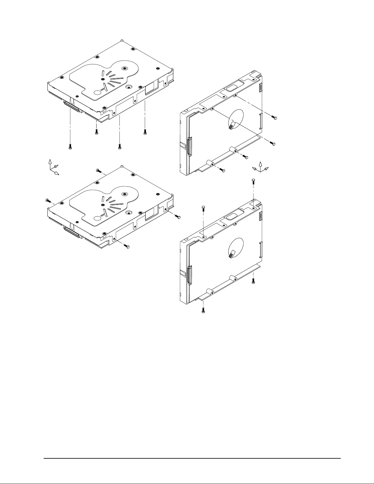
Cheetah 15K.6 FC Product Manual, Rev. C
39
Z
Y
X
Figure 11. Recommended mounting
X
Z
Y

40
Cheetah 15K.6 FC Product Manual, Rev. C
6.4.4.2 Vibration
a. Operating—normal
The drive as installed for normal operation, shall comply with the complete specified performance while
subjected to continuous vibration not exceeding
10–500 Hz @ 0.5 G (zero to peak)
Vibration may be applied in the X, Y, or Z axis.
Operating normal translational random flat profile
10–500 Hz 0.4 g RMS
b. Operating—abnormal
Equipment as installed for normal operation shall not incur physical damage while subjected to periodic
vibration not exceeding:
15 minutes of duration at major resonant frequency
10–500 Hz @ 0.75 G (X, Y, or Z axis)
Vibration occurring at these levels may degrade operational performance during the abnormal vibration
period. Specified operational performance will continue when normal operating vibration levels are
resumed. This assumes system recovery routines are available.
Operating abnormal translational random flat profile
10–500 Hz 1.2 g RMS
c. Non-operating
The limits of non-operating vibration shall apply to all conditions of handling and transportation. This
includes both isolated drives and integrated drives.
The drive shall not incur physical damage or degraded performance as a result of continuous vibration not
exceeding
5–500 Hz at 3G
Amplitudes above 1.0 G in the frequency range of 5-20 Hz may be limited due to shaker equipment stroke
limitations.
Vibration may be applied in the X, Y, or Z axis.
Non-operating translational random flat profile
10–500 Hz 1.2 g RMS
6.4.5 Acoustics
Sound power during idle mode shall be 3.5 bels typical when measured to ISO 7779 specification. Sound
power while operating shall be 3.7 bels typical when measured to ISO 7779 specification.
There will not be any discrete tones more than 10 dB above the masking noise on typical drives when measured according to Seagate specification 30553-001. There will not be any tones more than 24 dB above the
masking noise on any drive.
6.4.6 Air cleanliness
The drive is designed to operate in a typical office environment with minimal environmental control.
6.4.7 Corrosive environment
Seagate electronic drive components pass accelerated corrosion testing equivalent to 10 years exposure to
light industrial environments containing sulfurous gases, chlorine and nitric oxide, classes G and H per ASTM
B845. However, this accelerated testing cannot duplicate every potential application environment.

Cheetah 15K.6 FC Product Manual, Rev. C
41
Users should use caution exposing any electronic components to uncontrolled chemical pollutants and corrosive chemicals as electr onic dr i ve com ponen t reliab ilit y can be af fecte d by th e i nst allation environment. Th e si l-
ver, copper, nickel and gold films used in Seagate products are especially sensitive to the presence of sulfide,
chloride, and nitr ate c ont ami na nt s. S ulfur is found to be the m ost dam aging . In ad di tion, e lectron i c comp onent s
should never be exposed to condensing water on the surface of the printed circuit board assembly (PCBA) or
exposed to an am bient rel at ive hum idity gr eate r th an 9 5%. Mat erial s used in cabin et fa bri cation , such as vulcanized rubber, that can outgas corrosive compounds should be minimized or eliminated. The useful life of any
electronic equipment may be extended by replacing materials near circuitry with sulfide-free alternatives.
6.4.8 RoHS compliance statement
The European U nion Restr icti on of Hazard ous S ubst ance s (RoHS ) Dire cti ve re strict s the p resen ce of ch emic al
substances, including Lead (Pb), in electronic products effective July 2006.
A number of parts and materials in Seagate products are procured from external suppliers. We rely on the
representations of our suppliers regarding the presence of RoHS substances in these parts and materials. Our
supplier contracts require compliance with our chemical substance restrictions, and our suppliers document
their compliance wi th our re quire ment s by providing material conte nt declar ations for al l par ts an d mater ial s for
the disc drives documented in this publication. Current supplier declarations include disclosure of the inclusion
of any RoHS-regulated substance in such parts or materials.
Seagate also has internal system s in place to en sure ongoing complian ce with the RoHS Directive and all laws
and regulations which restrict chemical conte nt in electron ic produ cts. T hese system s include sta ndar d operating procedures that ensure that restricted substances are not utilized in our manufacturing operations, laboratory analytical validation testing, and an internal auditing process to ensure that we comply with all standard
operating procedures.
6.4.9 Electromagn etic susc ept ibili ty
See Section 2.1.1.1.

42
Cheetah 15K.6 FC Product Manual, Rev. C
6.5 Mechanical specifications
The following nominal dimensions are exclusive of the decorative front panel accessory. However, dimensions
of the front panel ar e shown in fi gu re belo w. Refer to Fig ure 1 2 for de ta ile d mou nting conf i gura tion dime nsi ons.
See Section 8.4, “Drive mounting.”
Height (max): 1.028 in 26.11 mm
Width (max): 4.010 in 101.85 mm
Depth (max): 5.787 in 146.99 mm
Weight: ST3450856FC: 1.563 pounds 0.709 kilograms
ST3300656FC: 1.53 pounds 0.694 kilograms
ST3146356FC: 1.487 pounds 0.674 kilograms
B
H
-Z-T//
REF
S
[1]
A
-Z-
M
L
R REF
-X-N
C
-X-
J
K
-Z-
Notes:
[1]
Mounting holes are 6-32 UNC 2B, three
on each side and four on the bottom.
Max screw penetration into side of drive
is 0.15 in. (3.81 mm). Max screw
tightening torque is 6.0 in-lb (3.32 nm)
with minimum full thread engagement of
0.12 in. (3.05 mm).
-X-U
P
F
[1]
E
D
Figure 12 . Mount ing configur a t ion dimensions
1.028
A
5.787
B
4.000
C
3.750
D
0.125
E
1.750
F
1.122
H
4.000
J
0.250
K
1.638
L
0.181
M
.040
N
1.625
P
1.618
R
0.276
S
.015
T
.015
U
Dimension Table
Inches
max
max
± .010
± .010
± .010
± .010
± .020
± .010
± .010
± .010
± .020
± .040
max
max
26.10
147.00
101.60
95.25
44.45
28.50
101.60
41.60
41.28
41.10
Millimeters
max
max
± .25
± .25
3.18
± .25
± .25
± .50
± .25
6.35
± .25
± .25
4.60
1.02
± .50
± 1.02
7.00
max
0.38
max
0.38

Cheetah 15K.6 FC Product Manual, Rev. C
43
7.0 Defect and error management
Seagate continues to use innovative technologies to manage defects and errors. These technologies are
designed to increase data integrity, perform drive self-maintenance, and validate proper drive operation.
SCSI defect and error manag eme nt involves drive inte rnal def ect/er ror manage ment and FC system er ror considerations (errors in communications between the initiator and the drive). In addition, Seagate provides the
following technologies used to increase data integrity and drive reliability:
• Background Media Scan (see Section 7.4)
• Media Pre-Scan (see Section 7.5)
• Deferred Auto-Reallocation (see Section 7.6)
• Idle Read After Write (see Section 7.7)
The read error rates and specified storage capacities are not dependent on host (initiator) defect management
routines.
7.1 Drive internal defects/errors
During the initial drive format operation at the factory, media defects are identified, tagged as being unusable,
and their locations recorded on the drive primary defects list (referred to as the “P’ list and also as the ETF
defect list). At factory format time, these known defects are also reallocated, that is, reassigned to a new place
on the medium and the location listed in the defects reallocation table. The “P” list is not altered after factory
formatting. Locations of defects found and reallocated during error recovery procedures after drive shipment
are listed in the “G” list (defects growth list). The “P” and “G” lists may be referenced by the initiator using the
Read Defect Data command.
Details of the SCSI commands supported by the drive are described in the Fibre Channel Interface Manual.
Also, more information on the drive Error Recovery philosophy is presented in the Fibre Channel Interface
Manual.
7.2 Drive er ror recov ery procedures
When an error occurs du ri ng dr ive ope ration, the drive, if program med t o do so, pe rfor ms er ror recove ry pro cedures to attempt to reco ver the dat a. T he err or r ecover y proce dure s used depend on the options pre viously set
in the Error Recovery Parameters mode page. Error recovery and defect management may involve using several SCSI commands described in the Fibre Channel Interface Manual. The drive implements selectable error
recovery time limits required in video applications.
The error r ecover y sche me suppo rted by t he d ri ve p rovide s a way to contr ol th e to tal error recovery time for the
entire command in addition to controlling the recovery level for a single LBA. The total amount of time spent in
error recovery for a command can be limited using the Recovery Time Limit bytes in the Error Recovery mode
page. The total amount of time spent in error recovery for a single LBA can be limited using the Read Retry
Count or Write Retry Count bytes in the Error Recovery mode page.
The drive firmware error recovery algorithms consists of 13 levels for read recoveries and five levels for write.
Each level may consist of multiple steps, where a step is defined as a recovery function involving a single re-

44
Cheetah 15K.6 FC Product Manual, Rev. C
read or re-write attempt. The maximum level used by the drive in LBA recovery is determined by the read and
write retry counts.
Table 8 equates the read and write retry count with the maximum possible recovery time for read and write
recovery of individual LBAs. The times given do not include time taken to perform reallocations. Reallocations
are performed when the ARRE bit (for reads) or AWRE bit (for writes) is one, the RC bit is zero, and the recovery time limit for the command has not yet been met. Time needed to perform reallocation is not counted
against the recovery time limit.
When the RC bit is one, reallocations are disabled even if the ARRE or AWRE bits are one. The drive will still
perform data recovery actions within the limits defined by the Read Retry Count, Write Retry Count, and
Recovery Time Limit parameters. However, the drive does not report any unrecovered errors.

Cheetah 15K.6 FC Product Manual, Rev. C
45
T ab le 8: Read and write retry count maximum recovery times [1]
Read retry
count
0 51.87 0 23.94
1 59.85 1 35.91
2 203.49 2 55.86
3 219.45 3 67.83
4 231.42 4 119.79
5 297.38 5 (default) 147.72
6 323.62
7 355.54
8 439.39
9 507.39
10 539.31
11 567.24
12 1,460.86
13 (default) 1,468.74
Maximum recovery time per LBA
(cumulative, msec)
Write retry
count
Maximum recovery time per LBA
(cumulative, msec)
[1] These values are subject to change.
Setting these retry counts to a value below the default setting could result in an increased unrecovered
error rate which may exceed the value given in this product manual. A setting of zero (0) will result in the
drive not performing error recovery.
For example, suppose the Read/Write Recovery page has the RC bit set to 0, read retry count set to 4,
and the recovery time limit field (Mode Sense page 01, bytes 10 and 11) set to FF FF hex (maximum). A
four LBA Read command is allowed to take up to 253.11 msec recovery time for each of the four LBAs in
the command. If the recovery time limit is set to 00 C8 hex (200 msec decimal) a four LB A read comm and
is allowed to take up to 200 msec for all error recovery within that command. The use of the Recovery
Time Limit field allows finer granularity on control of the time spent in error recovery. The recovery time
limit only starts counting when the drive is executing error recovery and it restarts on each command.
Therefore, each command’s total recovery time is subject to the recovery time limi t. Note: A recovery time
limit of 0 will use the drive’s default value of FF FF. Minimum recovery time limit is achieved by setting the
Recovery Time Limit field to 00 01.
7.3 FC-AL system errors
Information on the reporting of operational errors or faults across the interface is given in the Fibre Channel
Interface Manual. The FCP Response returns information to the host about numerous kinds of errors or faults.
The Receive Diagnostic Results reports the results of diagnostic operations performed by the drive.
Status returned by the drive to the initiator is described in the Fibre Channel Interface Manual. Status reporting
plays a role in systems err or manag ement and its use in that resp ect is d escribed in se ctions whe re t he va rious
commands are discussed.
7.4 Background Media Scan
Background Media Scan (BMS) is a self-initiated media scan. BMS is defined in the T10 document SPC-4
available from the T10 committee. BMS performs sequential reads across the entire pack of the media while
the drive is idle. In RAID arrays, BMS allows hot spare drives to be scanned for defects prior to being put into
service by the host system. On regular duty drives, if the host system makes use of the BMS Log Page, it can

46
Cheetah 15K.6 FC Product Manual, Rev. C
avoid placing data in suspect locations on the media. Unreadable and recovered error sites will be logged or
reallocated per ARRE/AWRE settings.
With BMS, the host system can consume less power and system overhead by only checking BMS status and
results rather th an tyi ng up th e bus a nd consu ming p ower i n the pr ocess o f host- initiated medi a scanning activity.
Since the backgr ound scan function s ar e o nl y don e d uring i dle p eriod s, B MS cau ses a neg lig ibl e imp a ct to system performance. The first BMS scan for a newly manufactured drive is performed as quickly as possible to
verify the media and protect data by setting the “Start time after idle” to 5ms, all subsequent scans begin after
500ms of idle time. Other features that normally use idle time to function will function normally because BMS
functions for bursts of 800ms and then suspends activity for 100ms to allow other background functions to
operate.
BMS interrupts immedi ately to service host com man ds from the inter face bus whi le pe rfor ming r eads. B MS will
complete any BMS-initiated error recovery prior to returning to service host-initiated commands. Overhead
associated with a return to host-servicing activity from BMS only impacts the first command that interrupted
BMS, this results in a typical delay of about 1 ms.
7.5 Media Pr e- Scan
Media Pre-Scan is a feature that allows the drive to repair media errors that would otherwise have been found
by the host system during critical data accesses early in the drive’s life. The default setting for Media Pre-Scan
is enabled on standard products. Media Pre-Scan checks each write command to determine if the destination
LBAs have been scanned by BMS. If the LBAs have been verified, the drive proceeds with the normal write
command. If the LBAs have not been verified by BMS, Pre-Scan will convert the write to a write verify to certify
that the data was properly written to the disc.
Note. During Pre-Scan write verify commands, write performance may decrease by 50% until Pre-Scan
completes. Write performance testing should be performed after Pre-Scan is complete. This may
be checked by reading the BMS status.
To expedite the scan of the full pack and subsequently exit from the Pre-Scan period, BMS will begin scanning
immediately when the drive goes to idle during the Pre-Scan period. In the event that the drive is in a high
transaction traffic environment and is unable to complete a BMS scan within 24 power on hours BMS will disable Pre-Scan to restore full performance to the system.
7.6 Deferred Auto-Reallocation
Deferred Auto-Reallocation (DAR) simplifies reallocation algorithm s at the system leve l by allowing the drive to
reallocate unreadable locations on a subsequent write command. Sites are marked for DAR during read operations performed by the drive. When a write command is received for an LBA marked for DAR, the auto-reallocation process is invoked and attempts to rewrite the data to the original location. If a verification of this rewrite
fails, the sector is re-mapped to a spare location.
This is in contrast to the system having to use the Reassign Command to reassign a location that was unreadable and then generate a write command to rewrite the data. DAR is most effective when AWRE and ARRE
are enabled—this is the default setting from the Seagate factory. With AWRE and ARRE disabled DAR is
unable to reallocate the failing location and will report an error sense code indicating that a write command is
being attempted to a previously failing location.
7.7 Idle Read After Write
Idle Read After Write (IRAW) utilizes idle time to verify the integrity of recently written data. During idle periods,
no active system requests, the drive reads recently written data from the media and compares it to valid write
command data resident in the drives data buffer. Any sectors that fail the comparison result in the invocation of
a rewrite and auto-reallocation process. The process attempts to rewrite the data to the original location. If a
verification of this rewrite fails, the sector is re-mapped to a spare location.

Cheetah 15K.6 FC Product Manual, Rev. C
47
8.0 Installation
Cheetah 15K.6 FC disc drive installation is a plug-and-play process. There are no jumpers, switches, or terminators on the drive. Simply plug the drive into the host’s 40-pin Fibre Channel backpanel connector (FCSCA)—no cables are required. See Section 9.5 for additional information about this connector.
Use the FC-AL interface to select drive ID and all option configurations for devices on the loop.
If multiple devices are on the same FC-AL and physical addresses are used, set the device selection ID s (SEL
IDs) on the backp anel so that no two devices have th e sam e select ion ID. T his is ca lled the har d assi gn ed arbi trated loop physical ad dress ( AL_PA). There are 125 AL_PAs available (see Table 30). If you set the AL _PA on
the backpanel to any value other than 0, the device plugged into the backpanel’s SCA connector inherits this
AL_PA. In the event you don’t successfully assign unique hard addresses (and therefore have duplicate selection IDs assigned to two or more devices), the FC-AL generates a message indicating this condition. If you set
the AL_PA on the backpanel to a value of 0, the system issues a unique soft-assigned physical address automatically.
Loop initialization is the process used to verify or obtain an address. The loop initialization process is performed when pow er is applied to the drive, whe n a device is added or removed from the F ibre Cha nnel loop , or
when a device times out attempting to win arbitration.
• Set all option selections in the connector prior to applying power to the drive. If you change options after
applying power to the drive, recycle the drive power to activate the new settings.
• It is not necessary to low-level format this drive. The drive is shipped from the factory low-level formatted in
512-byte logical blocks. You need to reforma t the drive only if you want to se lect a dif fer ent lo gical blo ck size.
8.1 Drive ID/option selection
All drive options are made through the interface connector (J1). Table 27 provides the pin descriptions for the
40-pin Fibre Channel single connector (J1).
8.2 Drive or ientat ion
The drive may be mounted in any orientation. All drive performance characterizations, however, have been
done with the drive in horizontal (discs level) and vertical (drive on its side) orientations, which are the two preferred mounting orientations.
8.3 Cooling
The host enclosure must dissipate heat from the drive. You should confirm that the host enclosure is designed
to ensure that the dr ive ope rate s w ithin the tempe ratu re m easur emen t guide lin es descr ibed in S ectio n 6.4. 1. In
some cases, forced airflow may be required to keep temperatures at or below the temperatures specified in
Section 6.4.1.

48
Cheetah 15K.6 FC Product Manual, Rev. C
If forced air is necessary, possible air-flow patterns are shown in Figure 13. The air-flow patterns are created
by fans either forcing or drawing air as shown in the illustrations. Conduction, convection, or other forced airflow patterns are acceptable as long as the temperature measurement guidelines of Section 6.4.1 are met.
Above unit
Note. Air flows in the direction shown (back to front)
or in reverse direction (front to back)
Note. Air flows in the direction shown or
in reverse direction (side to side)
Figure 13 . Air fl ow
Under unit
Above unit
Under unit
8.4 Drive mounting
Mount the drive usi ng the b ottom or side mo unting hol es. If you moun t the d rive u s ing the botto m ho les, ensure
that you do not physically distort the drive by attempting to mount it on a stiff, non-flat surface.
The allowable mounting surface stiffness is 80 lb/in (14.0 N/mm). The following equation and paragraph define
the allowable mounting surface stiffness:
where K is the mounting surface stiffness (units in lb/in or N/mm) and X is the out-of-plane surface distortion
(units in inches or millimeters). The out-of-plane distortion (X) is determined by defining a plane with three of
the four mounting points fixed and evaluating the out-of-plane deflection of the fourth mounting point when a
known force (F) is applied to the fourth point.
Note. Before mounting the drive in any kind of 3.5-inch to 5.25-inch adapter frame, verify with Seagate
Technology that the drive can meet the shock and vibration specifications given herein while
mounted in such an adapter frame. Adapter frames that are available may not have a mechanical
structure capable of mounting the drive so that it can meet the shock and vibration specifications
listed in this manual.
8.5 Grounding
Signal ground (PCBA) and HDA ground are connected together in the drive and cannot be separated by the
user. The equipment in which the drive is mounted is connected directly to the HDA and PCBA with no electri-
K x X = F < 15lb = 67N

Cheetah 15K.6 FC Product Manual, Rev. C
49
cally isolating shock mounts. If it is desired for the system chassis to not be connected to the HDA/PCBA
ground, the systems integrator or user must provide a nonconductive (electrically isolating) method of mounting the drive in the host equipment.
Increased radiated emissions may result if you do not provide the maximum surface area ground connection
between system ground and drive ground. This is the system designer’s and integrator’s responsibility.

50
Cheetah 15K.6 FC Product Manual, Rev. C

Cheetah 15K.6 FC Product Manual, Rev. C
51
9.0 Interface requirements
This section partially describes the interface requirements as implemented on Cheetah 15K.6 FC drives. Additional information is provided in the Fibre Channel Interface Manual (part number 100293070).
9.1 FC-AL feat ures
This section lists the Fibre Channel-specific features supported by Cheetah 15K.6 FC drives.
9.1.1 Fibre Channel link service frames
Table 9 lists the link services supported by Cheetah 15K.6 FC drives.
T ab le 9: Link services supported
Type of frame Link service
Basic link service frames Abort Sequence (ABTS)
Basic link service reply frames Basic_Accept (BA_ACC)
Extended link service frames N_Port Login (PLOGI)
Extended link service reply frames Accept (ACC)
Fibre Channel Services Register FC-4 Types (RFT_ID)
Basic_Reject (BA_RJT)
Fabric Login (FLOGI)
Logout (LOGO)
Process Login (PRLI)
Process Logout (PRLO)
Read Link Status (RLS)
Fabric Address Notification (FAN)
Port Discovery (PDISC)
Address Discovery (ADISC)
Third-party Process Logout (TRPLO)
Link Service Reject (LS_RJT)

52
Cheetah 15K.6 FC Product Manual, Rev. C
9.1.2 Fibre Channel task management functions
Table 10 lists the Fibre C hann el S CSI Fibre C han nel P roto col (F C S CSI FCP ) t ask mana geme nt fun cti ons su pported.
T ab le 10: Fibre Channel SCSI FCP task management functions
T ask name Su ppo rted
Term inate task No
Clear ACA Yes
Target reset Yes
Clear task set Yes
Abort task set Yes
9.1.3 Fibre Channel task management responses
Table 11 lists the FC SCSI FCP response codes returned for task management functions supported.
T ab le 11: FC SCSI FCP response codes
Function na m e Response c ode
Function complete 00
Function not supported 04
Function reject 05

Cheetah 15K.6 FC Product Manual, Rev. C
53
9.1.4 Fibre Channel port login
Table 12 identifies the required content of the N_Port Login (PLOGI) payload from an initiator.
T ab le 12: N_Port login (PLOGI) payload
Bytes
0-15 03 00 00 00 09 09 BB BB CF XX FS FS XX XX XX XX Common
16-31 XX XX XX XX PN PN PN PN PN PN PN PN NN NN NN NN
32-35 NN NN NN NN
36-47 XX XX XX XX XX XX XX XX XX XX XX XX Class 1
48-51 XX XX XX XX
52-63 XX XX XX XX XX XX XX XX XX XX XX XX Class 2
64-67 XX XX XX XX
68-79 SO SO IC IC XX XX FS FS XX CS XX XX Class 3
80-83 OS OS XX XX
84-95 XX XX XX XX XX XX XX XX XX XX XX XX Reserved
96-99 XX XX XX XX
100-111 XX XX XX XX XX XX XX XX XX XX XX XX Vendor
112-115 XX XX XX XX Version
X Indicates a four-bit (hex) field is not checked.
x Indicates a single bit is not checked.
BB BB-Credit. This field is not checked. The FC-AL drive uses BB-Credit of zero (0).
CF Common features. This binary field selects the common features requested by the initiator login.
MSB Continuously increasing offset Must = 1
Random relative offset Not checked. Port Login Accept will return a 0—not supported.
Valid version level x
N_Port/F_Port Must = 0, N_Port
Alternate credit model Must = 1
Other bits reserved xxx XX
FS Receive buffer field size. The FS field in the common and Class 3 parameters is checked for the range 128 < FS < 2,112 and a
multiple of four bytes. For multiple frame sequences, all frames but the last frame of the sequence must be this size. Only the
receive buffer field size in the Class 3 parameters is used.
PN Port name (initiator’s)—saved with the login parameters. If a change of the port name/AL_PA address association is detected
during a Port DISCovery, and implicit logout occurs and the initiator returns a LS_RJT.
NN Node name. The node name is not checked or saved by the drive.
SO Service options Class 3 only.
MSB Class valid Must = 1
Intermix x
Stacked connection req. xx
Sequential delivery x
Other bits reserved xxx XX
IC Initiator control
MSB XID reassign xx
Proc Assc 10 or 11 causes the login to be rejected. Other values are accepted.
Other bits XXX
CS Concurrent sequences Must be a value greater than 0.
OS Open sequences per exchange Must be a value greater than 0.

54
Cheetah 15K.6 FC Product Manual, Rev. C
9.1.5 Fibre Channel port login accept
Table 13 identifies the N_Port Login access payload values.
T ab le 13: N_Port Login Accept (ACC) payload
Bytes
0-15 02 00 00 00 09 09 00 00 88 00 FS FS 00 FF 00 01 Common
16-31 00 00 01 F4 2P 00 CC CC CC UI UI UI 20 00 CC CC
32-35 CC UI UI UI
36-47 00 00 00 00 00 00 00 00 00 00 00 00 Class 1
48-51 00 00 00 00
52-63 00 00 00 00 00 00 00 00 00 00 00 00 Class 2
64-67 00 00 00 00
68-79 80 00 00 00 00 00 FS FS 00 FF 00 00 Class 3
80-83 00 01 00 00
84-95 00 00 00 00 00 00 00 00 00 00 00 00 Reserved
96-99 00 00 00 00
100-111 00 00 00 00 00 00 00 00 00 00 00 00 Vendor 112-11500000000 Version
CC Bytes (22, 23 and 24) and (30, 31 and 32) are currently factory set to 00 04 CF respectively (subject to change).
FS Receive buffer field size. The drive returns and uses the receive buffer size from the N_Port Login Class 3 receive buffer.
UI Unique identifier. This 24-bit field is uniquely assigned to the drive. This same UI appears in the Port Name and Node Name
fields.
P Byte port identifier field.
0 P_LOGI received on Node.
1 P_LOGI received on Port A.
2 P_LOGI received on Port B.
9.1.6 Fibre Channel Process Login
Table 14 lists the process login payload data.
T ab le 14: Process Login (PLRI) payload
Bytes
0-15 20 10 00 14 08 00 20 00 XX XX XX XX XX XX XX XX
16-19 00 00 00 22
XX Indicates fields that are not used.

Cheetah 15K.6 FC Product Manual, Rev. C
55
9.1.7 Fibre Channel Process Login Accept
Table 15 lists Cheetah 15K.6 FC process login accept payload data.
T ab le 15: Process Login Accept (ACC) payload
Bytes
0-15 02 10 00 14 08 00 21 00 00 00 00 00 00 00 00 00
16-31 00 00 00 12
9.1.8 Fibre Channel fabric login
Table 16 lists the fabric login payload from the drive.
Table 16: Fabric Login (FLOGI) payload
Bytes
0-15 04 00 00 00 09 09 00 00 08 00 08 40 00 00 00 00 Common
16-31 00 00 02 F4 2P 00 CC CC CC UI UI UI 02 00 CC CC
32-35 CC UI UI UI
36-47 00 00 00 00 00 00 00 00 00 00 00 00 Class 1
48-51 00 00 00 00
52-63 00 00 00 00 00 00 00 00 00 00 00 00 Class 2
64-67 00 00 00 00
68-79 80 00 00 00 00 00 08 40 00 00 00 00 Class 3
80-83 00 00 00 00
84-95 00 00 00 00 00 00 00 00 00 00 00 00 Reserved
96-99 00 00 00 00
100-111 00 00 00 00 00 00 00 00 00 00 00 00 Vendor 112-11500000000 Version
CC Bytes (22, 23 and 24) and (30, 31 and 32) are currently factory set to 00 04 CF respectively (subject to change).
UI Unique identifier. This 24-bit field is uniquely assigned to the drive. This same UI appears in the Port Name and Node Name
fields.
P Port id entifier field.
1 FLOGI originated on Port A.
2 FLOGI originated on Port B.

56
Cheetah 15K.6 FC Product Manual, Rev. C
9.1.9 Fibre Channel fabric accept login
Table 17 lists the required content of the Fabric Login Accept (ACC) payload from the fabric.
T ab le 17: Fabric Login Accept (ACC) payload
Bytes
0-15 02 00 00 00 09 09 BB BB CF XX FS FS R_ A_ T0 V_ Common
16-31 E_ D_ T0 V_ PN PN PN PN PN PN PN PN NN NN NN NN
32-35 NN NN NN NN
36-47 XX XX XX XX XX XX XX XX XX XX XX XX Class 1
48-51 XX XX XX XX
52-63 XX XX XX XX XX XX XX XX XX XX XX XX Class 2
64-67 XX XX XX XX
68-79 SO SO xx xx XX XX FS FS XX xx XX XX Class 3
80-83 OS OS XX XX
84-95 XX XX XX XX XX XX XX XX XX XX XX XX Reserved
96-99 XX XX XX XX
100-111 XX XX XX XX XX XX XX XX XX XX XX XX Vendor 112-115XXXXXXXX Version
X Indicates a four-bit (hex) field is not checked.
x Indicates a single bit is not checked.
BB BB-Credit. This field is not checked. The FC-AL drive uses BB-Credit of zero (0).
CF Common features. This binary field selects the common features requested by the fabric login.
MSB Continuously increasing offset x
Random relative offset x
Valid version level x
N_Port/F_Port Must = 1, F_Port
Alternate credit model Must = 1
Other bits reserved xxx XX
FS Receive buffer field size. The FS field in the common and Class 3 parameters is checked for the range 128 < FS < 2,112 and a
multiple of four bytes. The receive buffer field size in the Class 3 parameters is used. The drive uses the lower FS of Fabric
Login Accept or N_Port Login when sending frames to an initiator.
PN Port Name. The fabric port name is saved with the login parameters. If a change of the port name is detected during a FAN, an
implicit logout occurs and a LS_RJT is returned to the fabric.
NN Node Name. The drive does not check or save the node name.
SO Service Options—Class 3 only.
MSB Class valid Must = 1
Intermix x
Stacked connection req. xx
Sequential delivery Must = 1
Other bits reserved xxx XX

Cheetah 15K.6 FC Product Manual, Rev. C
57
9.1.10 Fibre Channel Arbitrated Loop options
Table 18 lists the FC-AL options supported by Cheetah 15K.6 FC drives.
T ab le 18: FC-AL options supported
Option Supported
OPEN Half Duplex Accepted from another device.
OPEN Full Duplex Sent to open another device. Accepted from another device.
Private Loop Yes
Public Loop Yes
Old Port State No
Loop Position Yes
Loop Position Report Yes
9.2 Dual port support
Cheetah 15K.6 FC drives have two independent FC-AL ports. These ports may be connected on independent
loops or on the same loop. Port A and Port B may be connected in any order or combination.
• If both ports ar e conn ected on i nde pend ent loo ps and h ard a ddre ssi ng is use d, the driv e in terfa ce add ress i s
selected through the interface connector, both ports will seek the same loop address. If no conflict, both
ports will have the same loop address.
• If both ports are connected in the same loop and hard addressing is used, at least one port will attempt taking a soft address to prevent an address conflict.
Note. When a Cheetah 15K.6 FC drive is connected in loops with previous Seagate FC drive products:
Barracuda 4LP FC (ST32171FC, ST34371FC, and ST34571FC)
Barracuda 9FC (ST19171FC)
Cheetah 4LP FC (ST34501FC)
Cheetah 9FC (ST19101FC)
the connection of Port A and B for these products must follow the requirements in their product manuals.
Subject to buffer availability, the Cheetah 15K.6 FC drives support:
• Concurrent port transfers—The drive supports receiving transfers on both ports at the same time when the
ports are on independent loops.
• Full duplex—The drive supports sending FCP_Data, FCP_RSP, FCP_XFR_RDY and ELS transfers while
receiving frames on both ports.
9.3 SCSI commands supported
Table 19 lists the SCSI commands supported by Cheetah 15K.6 FC drives.

58
Cheetah 15K.6 FC Product Manual, Rev. C
T ab le 19: Supported commands
Executable state of standard SCSI commands in the presence of
LBA banding (applies to FDE models only)
Affected LBA
User Data
Command
code
00h Y Test unit ready Y N Executable Executable
01h Y Rezero unit Y N Executable Executable
03h Y Request sense Y N Executable Executable
04h Y Format unit [1] Y Y Executable Check Condition
07h Y Reassign blocks N Y Executable Check Condition
08h Y Read N Y Executable Check Condition
0Ah Y Write N Y Executable Check Condition
0Bh Y Seek N N Executable Executable
12h Y Inquiry Y N Executable Executable
15h Y Mode select (same pages as Mode
16h Y Reserve Y N Executable Executable
17h Y Release Y N Executable Executable
18h N Copy
1Ah Y Mode sense Y N Executable Exec utable
Supported
(Y/N) [4] Command nam e
Y Extended sense
Y Field pointer bytes
Y Actual retry count bytes
Y Vital product data page (00h)
Y Unit serial number page (80h)
Y Implemented operating def. page
(81h)
Y Device Identification page (83h)
Y Firmware numbers page (C0h)
Y Date code page (C1h)
Y Jumper settings page (C2h)
Y Device Behavior page (C3h)
Sense command shown below) [3]
N 3rd party reserved
N Extent reservation
Y Unit attention page (00h)
Y Error recovery page (01h)
Y Disconnect/reconnect control (page
02h)
Y Format page (03h)
Y Rigid disc drive geometry page
(04h)
Y Verify error recovery page (07h)
Y Caching parameters page (08h)
Y Control mode page (0Ah)
Y Fibre Channel Interface Control
page (19h)
Affects entire
Drive (Y/N)
Y N Executable Executable
Accessed
(Y/N)
Unlocked
ReadLock=Write
Lock=False
Affected LBA
Locked
ReadLock=Write
Lock=True

Cheetah 15K.6 FC Product Manual, Rev. C
59
T ab le 19: Supported commands (continued)
Executable state of standard SCSI commands in the presence of
LBA banding (applies to FDE models only)
Affected LBA
User Data
Command
code
1Bh Y Start unit/stop unit Y Y Executable Executable
1Ch Y Receive diagnostic results Y N Executable Executable
1Dh Y Send diagnostics page Y N Executable Executable
25h Y Read capacity Y N Executable Executable
28h Y Read extended
2Ah Y Write extended
2Bh Y Seek extended
2Eh Y Write and verify N Y Executable Check Condition
2Fh Y Verify (10) (BYTCHK = 0) N Y Executable Executable
30h N Search data high
31h N Search data equal
32h N Search data low
33h N Set limits
34h N Prefetch N Y Executable Check Condition
35h Y Synchronize cache N Y Executable Executable
36h N Lock-unlock-cache
37h Y Read defect data Y N Executable Executable
39h N Compare
Supported
(Y/N) [4] Command nam e
Y Power control page (1Ah)
Y Information exceptions control page
(1Ch)
Y Background Scan mode subpage
(01h)
Y Supported diagnosti cs pages
Y Translate page
Y Enclosure services page
Y Supported diagnosti cs pages
Y Translate page
Y Disable page out
Y Force unit access
N Relative address
Y Disable page out
Y Force unit access
N Relative address
Y Disable page out
Y Byte check
N Relative address
Y Verify (10) (BYTCHK = 1) N Y Execut able Check Conditi on
Y Disable page out
Y Byte check
N Relative address
Affects entire
Drive (Y/N)
Accessed
(Y/N)
Unlocked
ReadLock=Write
Lock=False
Affected LBA
Locked
ReadLock=Write
Lock=True

60
Cheetah 15K.6 FC Product Manual, Rev. C
T ab le 19: Supported commands (continued)
Executable state of standard SCSI commands in the presence of
LBA banding (applies to FDE models only)
Affected LBA
User Data
Command
code
3Ah N Copy and verify
3Bh Y Write buffer N Y Check Condition Check Condition
3Ch Y Read buffer (Mode 1Ch -- Error
3Ch Y Read buffer Y N Check Condition Check Condition
3Eh Y Read long N Y Check Condition Check Condition
3Fh Y Write long (10) (WR_UNCOR = 0) N Y Check Condition Check Condition
40h N Change definition Y N Executable Check Condtion
41h Y Write same (10) N Y Executable Check Condition
42-4Bh N Not used
4Ch Y Log Select Y N Executable Executable
4Dh Y Log Sense Y N Executable Executable
Supported
(Y/N) [4] Command nam e
Y Write combined header and data
mode (0)
Y Write data mode (2)
N Download microcode mode (4)
Y Download microcode and save
modes (5)
N Download microcode with offsets
mode (6)
Y Download microcode with offsets
and save mode (7)
Y Firmware download option [2]
Retrieval Mode)
Y Read combined header and data
mode (0)
Y Read data mode (2)
Y Read descriptor mode (3)
Write long (10) (WR_UNCOR = 1) N Y Executable Check Condition
NPBdata
N LBdata
Y Support Log page (00h)
Y Write Error Counter page (02h)
Y Read Error Counter page (03h)
N Read Reverse Error Counter page
(04h)
Y Verify Error Counter page (05h)
Y Non-medium Error Counter page
(06h)
Y Temperature page (0Dh)
N Application Client page (0Fh)
Y Self Te st Results page (10h)
Affects entire
Drive (Y/N)
Y N Executable Executable
Y N Executable Executable
Accessed
(Y/N)
(all modes except modes 4h - 7h, 0Eh, and 0Fh)
(modes 4h - 7h, 0Eh, and 0Fh)
Unlocked
ReadLock=Write
Lock=False
Affected LBA
Locked
ReadLock=Write
Lock=True

Cheetah 15K.6 FC Product Manual, Rev. C
61
T ab le 19: Supported commands (continued)
Executable state of standard SCSI commands in the presence of
LBA banding (applies to FDE models only)
Affected LBA
User Data
Command
code
4E-4Fh N Not used
50h N XD wri t e
51h N XP write
52h N XD read
53-54h N Not used
55h Y Mode Select (10) [3]
56h Y Reserved (10)
57h Y Released (10)
58-59h N Not used
5Ah Y Mode Sense (10) [3]
5B-5Dh N Not used
5E A Persistent reserve in Y N Executable Executable
5F A Persistent reserve out Y N Executable Executable
60-7Eh N Not used
7Fh Y (PI only) Write Same (32) N Y Executable Check Condition
7Fh Y (PI only) Verify (32) (BYTCHK = 0) N Y Executable Executable
7Fh Y (PI only) Verify (32) (BYTCHK = 1) N Y Executable Check Condition
80h N XD write extended
81h N Rebuild
82h N Regenerate
83-8Eh N Not used
8Fh Y (PI only) Verify (16) (BYTCHK = 0) N Y Executable Executable
8Fh Y (PI only) Verify (16) (BYTCHK = 1) N Y Executable Check Condition
93h Y (PI only) Write same (16) N Y Executable Check Condition
A0h Y Report LUNS Y N Executable Executable
A2h Y
A3h Y
B5h Y
C0-DFh N Not used
EO-FFh N Not used
Supported
(Y/N) [4] Command nam e
Y Background Medium Scan page
(15h)
Y Cache Statistics Counter page (37h)
Y Factory Log page (3Eh)
Y 3rd party reserve
N Extent reservation
Security Protocol In Y N Executable Executable
(FDE only)
Report Device Identifier Y N Executable Executable
(FDE only)
Security Protocol Out Y N Executable Executable
(FDE only)
Affects entire
Drive (Y/N)
Accessed
(Y/N)
Unlocked
ReadLock=Write
Lock=False
Affected LBA
Locked
ReadLock=Write
Lock=True
[1] Cheetah 15K.6 FC drives can format to 512, 520, 524 or 528 bytes per logical block.
[2] Warning. Power loss during flash programming can result in firmware corruption. This usually makes the
drive inoperable.

62
Cheetah 15K.6 FC Product Manual, Rev. C
[3] Reference Mode Sense command 1Ah for mode pages supported.
[4] Y = Yes. Command is supported.
N = No. Command is not supported.
A = Support is available on special request.
9.3.1 Inquiry data
Table 20 lists the Inquiry command data that the drive should return to the initiator per the format given in the
Fibre Channel Interface Manual.
T ab le 20: Cheetah 15K.6 FC inquiry data
Bytes Data (hex)
0-15 00 00 xx** 12 8B 00 PP 0A 53 45 41 47 41 54 45 20 Vendor ID
16-31 [535433 3435303835364643]120 20 20 20 20 Product ID
32-47 R# R# R# R# S# S# S# S# S# S# S# S# 00 00 00 00
48-63 00 00 00 00 00 00 00 00 00 00 00 00 00 00 00 00
64-79 00 00 00 00 00 00 00 00 00 00 00 00 00 00 00 00
80-95 00 00 00 00 00 00 00 00 00 00 00 00 00 00 00 00
96-111 00 43 6F 70 79 72 69 67 68 74 20 28 63 29 20 32* *Copyright
112-127 30* 30* 37* 20 53 65 61 67 61 74 65 20 41 6C 6C 20 notice
128-143 72 69 67 68 74 73 20 72 65 73 65 72 76 65 64 20
* Copyright year (changes with actual year).
** SCSI Revision support. Refer to the SPC release documentation for definitions.
PP 50 = Inquiry data for an Inquiry command received on Port A.
70 = Inquiry data for an Inquiry command received on Port B.
R# Four ASCII digits representing the last four digits of the product firmware release number.
S# Eight ASCII digits representing the eight digits of the product serial number.
[ ] Bytes 18 through 26 reflect model of drive. The table above shows the hex values for Model ST3450856FC.
Refer to the values below for the values of bytes 18 through 26 of you particular model:
ST3450056FC 53 54 33 34 35 30 30 35 36 46 43
ST3300656FC 53 54 33 33 30 30 36 35 36 46 43
ST3300056FC 53 54 33 33 30 30 30 35 36 46 43
ST3146356FC 53 54 33 31 34 36 33 35 36 46 43
ST3146756FC 53 54 33 31 34 36 37 35 36 46 43
9.3.2 Mode Sense data
The Mode Sense command provides a way for the drive to report its operating parameters to the initiator. The
drive maintains four sets of mode parameters:
1. Default values
Default values are hard-coded in the drive firmware stored in flash E-PROM (nonvolatile memory) on the
drive’s PCB. These default values can be changed only by downloading a complete set of new firmware
into the flash E-PROM. An initiator can request and receive from the drive a list of default values and use
those in a Mode Select command to set up new current and saved values, where the values are changeable.
2. Saved values
Saved values are stored on the drive’s media using a Mode Select command. Only parameter values that
are allowed to be chang ed c an b e cha nged by th i s me thod. Pa ram eters in th e save d va lues l ist that are not
changeable by the Mode Select command get their values from default values storage.

Cheetah 15K.6 FC Product Manual, Rev. C
63
When power is applied to the drive, it takes saved values from the media and stores them as current values in volatile memory. It is not possible to change the current values (or the saved values) with a Mode
Select command before the drive achieves operating speed and is “ready.” An attempt to do so results in a
“Check Condition” status.
On drives requiring unique saved values, the required unique saved values are stored into the saved values storage location on the media prior to shipping the drive. Some drives may have unique firmware with
unique default values also.
On standard OEM drives, the saved values are taken from the default values list and store d into the saved
values storage location on the media prior to shipping.
3. Current values
Current values are volatile values bei ng used by the driv e to contro l its operation. A Mod e S elect comm and
can be used to change the values identified as changeable values. Originally, current values are installed
from saved or default values after a power on reset, hard reset, or Bus Device Reset message.
4. Changeable values
Changeable values for m a bit mask, stored in no nvolatil e me mor y, that dictates which of the current values
and saved values can be changed by a Mode Select command. A one (1) indicates the value can be
changed. A zero (0) indicates the value is not changeable. For example, in Table 21, refer to Mode page
81, in the row entitled “CHG.” These are hex numbers representing the changeable values for Mode page
81. Note in colu mns 5 and 6 ( bytes 0 4 an d 05) , th ere is 00h w hich ind icates that in bytes 04 and 05 none of
the bits are changeable. Note also that bytes 06, 07, 09, 10, and 11 are not changeable, because those
fields are all zeros. In byte 02 , hex val ue FF equates to the binary patter n 11111111. If there is a zero in any
bit position in the field, it means that bit is not changeable. Since all of the bits in byte 02 are ones, all of
these bits are changeable.
The changeable values list can only be changed by downloading new firmware into the flash E-PROM.
Note. Because there are often several dif feren t versi on s of dr ive contr ol firm ware in the total population of
drives in the field , the Mode Sense values given in the followi ng ta bles m ay not exactly m atch t hose
of some drives.
The following table s list the values of the dat a bytes returned by the drive in response to the Mode Sense command pages for SCSI implementation (see the Fibre Channel Interface Manual ).
Definitions:
SAV = Current saved value.
DEF = Default value. Standard OEM drives are shipped configured this way.
CHG = Changeable bits; indicates if default value is changeable.

64
Cheetah 15K.6 FC Product Manual, Rev. C
T ab le 21: Mode Sense data saved, default and changeable values for ST3450856FC/ST3450056FC drives
MODE DATA HEADER:
00 be 00 10 00 00 00 08
MODE PAGES:
DEF 81 0a c0 0b ff 00 00 00 05 00 ff ff
CHG 81 0a ff ff 00 00 00 00 ff 00 ff ff
DEF 82 0e 80 80 00 00 00 00 00 00 01 3a 00 00 00 00
CHG 82 0e ff ff 00 00 00 00 00 00 ff ff 00 00 00 00
DEF 83 16 bb d0 00 00 00 00 03 80 04 c4 02 00 00 01 01 09 00 5f 40 00 00 00
CHG 83 16 00 00 00 00 00 00 00 00 00 00 00 00 00 00 00 00 00 00 00 00 00 00
DEF 84 16 02 57 08 08 00 00 00 00 00 00 00 00 00 00 00 00 00 00 3a a7 00 00
CHG 84 16 00 00 00 00 00 00 00 00 00 00 00 00 00 00 00 00 00 00 00 00 00 00
DEF 87 0a 00 0b ff 00 00 00 00 00 ff ff
CHG 87 0a 0f ff 00 00 00 00 00 00 ff ff
DEF 88 12 14 00 ff ff 00 00 ff ff ff ff 80 20 00 00 00 00 00 00
CHG 88 12 a5 00 00 00 ff ff ff ff 00 00 20 00 00 00 00 00 00 00
DEF 8a 0a 02 00 00 00 00 00 00 00 0e c4
CHG 8a 0a 03 f0 00 00 00 00 00 00 00 00
DEF 99 06 00 00 00 00 00 00
CHG 99 06 00 ff 00 00 00 00
DEF 9a 0a 00 02 00 00 00 05 00 00 00 04
CHG 9a 0a 00 03 ff ff ff ff 00 00 00 00
DEF 9c 0a 10 00 00 00 00 00 00 00 00 01
CHG 9c 0a 9d 0f ff ff ff ff ff ff ff ff
DEF 80 06 00 80 0f 00 00 00
CHG 80 06 b7 c0 0f 00 00 00
READ CAPACITY DATA:
READ BUFFER
0 1 2 3 4 5 6 7 8 9 A B C D E F ASCII
000000: 34 65 F8 6F 00 00 02 00 __ __ __ __ __ __ __ __ 4e.o....

Cheetah 15K.6 FC Product Manual, Rev. C
65
T ab le 22: Mode Sense data default and changeable values for ST3300656FC/ST3300056FC drives
MODE DATA HEADER:
00 be 00 10 00 00 00 08
MODE PAGES:
DEF 81 0a c0 0b ff 00 00 00 05 00 ff ff
CHG 81 0a ff ff 00 00 00 00 ff 00 ff ff
DEF 82 0e 80 80 00 00 00 00 00 00 01 3a 00 00 00 00
CHG 82 0e ff ff 00 00 00 00 00 00 ff ff 00 00 00 00
DEF 83 16 bb d0 00 00 00 00 03 80 04 c4 02 00 00 01 01 09 00 5f 40 00 00 00
CHG 83 16 00 00 00 00 00 00 00 00 00 00 00 00 00 00 00 00 00 00 00 00 00 00
DEF 84 16 02 57 08 06 00 00 00 00 00 00 00 00 00 00 00 00 00 00 3a a7 00 00
CHG 84 16 00 00 00 00 00 00 00 00 00 00 00 00 00 00 00 00 00 00 00 00 00 00
DEF 87 0a 00 0b ff 00 00 00 00 00 ff ff
CHG 87 0a 0f ff 00 00 00 00 00 00 ff ff
DEF 88 12 14 00 ff ff 00 00 ff ff ff ff 80 20 00 00 00 00 00 00
CHG 88 12 a5 00 00 00 ff ff ff ff 00 00 20 00 00 00 00 00 00 00
DEF 8a 0a 02 00 00 00 00 00 00 00 09 9c
CHG 8a 0a 03 f0 00 00 00 00 00 00 00 00
DEF 99 06 00 00 00 00 00 00
CHG 99 06 00 ff 00 00 00 00
DEF 9a 0a 00 02 00 00 00 05 00 00 00 04
CHG 9a 0a 00 03 ff ff ff ff 00 00 00 00
DEF 9c 0a 10 00 00 00 00 00 00 00 00 01
CHG 9c 0a 9d 0f ff ff ff ff ff ff ff ff
DEF 80 06 00 80 0f 00 00 00
CHG 80 06 b7 c0 0f 00 00 00
READ CAPACITY DATA:
READ BUFFER
0 1 2 3 4 5 6 7 8 9 A B C D E F ASCII
000000: 22 EC B2 5B 00 00 02 00 __ __ __ __ __ __ __ __ "..[....

66
Cheetah 15K.6 FC Product Manual, Rev. C
T ab le 23: Mode Sense data default and changeable values for ST3146356FC/ST3146756FC drives
MODE DATA HEADER:
00 be 00 10 00 00 00 08
MODE PAGES:
DEF 81 0a c0 0b ff 00 00 00 05 00 ff ff
CHG 81 0a ff ff 00 00 00 00 ff 00 ff ff
DEF 82 0e 80 80 00 00 00 00 00 00 01 3a 00 00 00 00
CHG 82 0e ff ff 00 00 00 00 00 00 ff ff 00 00 00 00
DEF 83 16 bb d0 00 00 00 00 03 80 04 c4 02 00 00 01 01 09 00 5f 40 00 00 00
CHG 83 16 00 00 00 00 00 00 00 00 00 00 00 00 00 00 00 00 00 00 00 00 00 00
DEF 84 16 02 57 08 03 00 00 00 00 00 00 00 00 00 00 00 00 00 00 3a a7 00 00
CHG 84 16 00 00 00 00 00 00 00 00 00 00 00 00 00 00 00 00 00 00 00 00 00 00
DEF 87 0a 00 0b ff 00 00 00 00 00 ff ff
CHG 87 0a 0f ff 00 00 00 00 00 00 ff ff
DEF 88 12 14 00 ff ff 00 00 ff ff ff ff 80 20 00 00 00 00 00 00
CHG 88 12 a5 00 00 00 ff ff ff ff 00 00 20 00 00 00 00 00 00 00
DEF 8a 0a 02 00 00 00 00 00 00 00 06 cc
CHG 8a 0a 03 f0 00 00 00 00 00 00 00 00
DEF 99 06 00 00 00 00 00 00
CHG 99 06 00 ff 00 00 00 00
DEF 9a 0a 00 02 00 00 00 05 00 00 00 04
CHG 9a 0a 00 03 ff ff ff ff 00 00 00 00
DEF 9c 0a 10 00 00 00 00 00 00 00 00 01
CHG 9c 0a 9d 0f ff ff ff ff ff ff ff ff
DEF 80 06 00 80 0f 00 00 00
CHG 80 06 b7 c0 0f 00 00 00
READ CAPACITY DATA:
READ BUFFER
0 1 2 3 4 5 6 7 8 9 A B C D E F ASCII
000000: 11 17 73 2F 00 00 02 00 __ __ __ __ __ __ __ __ ..s/....

Cheetah 15K.6 FC Product Manual, Rev. C
67
9.4 Miscellaneous operating features and conditions
Table 24 lists various features and conditions. A “Y” in the support column indicates the feature or condition is
supported. An “N” in the support column indicates the feature or condition is not supported.
T ab le 24: Miscellaneous features
Suppor t e d Feature or co ndition
Y FC-AL select i ve r e set (LIP Res e t)
N Automatic contingent allegiance
N Asynchronous event notification
N Synchronized (locked) spindle operation
Y Segmented caching
N Zero latency read
Y Queue tagging (up to 128 queue tags supported)
Y Deferred error handling
Y Parameter rounding (controlled by Round bit in Mode Select page 0)
Y Reporting actual retry count in Extended Sense bytes 15, 16, and 17
N Adaptive caching
Y SMP = 1 in Mode Select command needed to save RPL and rotational offset bytes
T ab le 25: Miscellaneous status
Supported Status
Y Good
Y Check condition
Y Condition met/good
YBusy
Y Intermediate/good
Y Intermediate/condition met/good
Y Reservation conflict
Y Task set full
N ACA active
N ACA active, faulted initiator

68
Cheetah 15K.6 FC Product Manual, Rev. C
9.5 FC-AL physical interface
Port Bypass
Figure 14 shows the location of the J1 Fibre Channel single connection attachment (FC-SCA). Figure 16 provides the dimensions of the FC-SCA connector.
Details of the physical, electrical, and logical characteristics are provided within this section. The operational
aspects of Seagate’s Fibre Channel drives are provided in the Fibre Channel Interface Manual..
J1 interface connector
Figure 14. Physical interface
9.5.1 Physical character istic s
This section defines physical interface connector.
9.5.1.1 Physical descriptio n
FIbre Channel drives may be connected in a loop together or with other compatible FC-AL devices. A maximum of 127 devices may have addresses; however, one of the addresses is reserved for a fabric port switch
device. This means 126 addresses are available for FC-AL devices. More FC-AL compatible devices may
physically reside on the loop, but they will not be functional because they would not be able to obtain valid
addresses.
Port bypass circuits (PBCs) allow devices to be inserted into unpopulated locations or removed from the loop
with loop operation recovery after a brief interruption. These PBCs are located external to the FC-AL device.
Figure 15 shows the relationship between the PBC and FC-AL device.
Circuit
From Previous
Port Bypass
Circuit N–1
Drive N–1
Drive
MUX
Select
SerialInSerial
Drive N
Out
To Next
Drive
Port Bypass
Circuit N+1
Drive N+1
Figure 15. Port bypass circuit physical interconnect
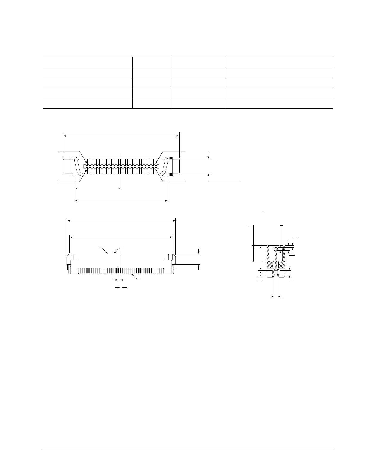
Cheetah 15K.6 FC Product Manual, Rev. C
69
9.5.2 Connector requirements
P
P
s
(1.30 ± 0.16 mm)
T ab le 26: Recommended mating SCA part numbers
Part description Positions Part number Features
AMP Vertical (SCA sequence) 40 787317-1
Berg 40 71781
Methode 40 512-220-91-101N
Molex 40 717431040
With polarization
With polarization
With polarization
With polarization
The FC-AL SCA device connector is illustrated in Figure 16.
1.618 ± .003 in
(41.1 ± 0.08 mm)
in 20
in 40
.64 in
(16.24 mm)
1.28 in
(32.47 mm)
1.618 ± .003 in
(41.10 ± 0.08 mm)
1.492 ± .009 in
(37.90 ± 0.24 mm)
Mating end Housing
.05 in
(1.27 mm)
typ.
.025 in (0.635 mm)
Contact (typ.)
Pin 1
Pin 21
0.264+.007 in
–.010 in
(6.71+0.18 mm)
(–0.25 mm)
0.197 ± .003 in
(5.00 ± .08 mm)
0.226 in
(6.50 mm)
0.106 ± .010 in
(2.70 ± 0.25 mm)
2 places
min.
0.394 ± .004 in
(10.0 ± 0.10 mm)
0.039 in
(0.75 mm)
0.051 ± .006 in
min.
0.024 in
(0.60 mm)
0.079 ± .010 in
(2.00 ± .25 mm)
0.060 ± .010 in
(1.52 ± 0.25 mm)
min.
(initial point
of contact)
2 place
Figure 16 . FC-A L S CA device conne c t or dimensions
9.5.3 Electrical description
Fibre Channel drives use the FC-SCA connector for:
• DC power
• FC-AL interface
• Drive select (device identification)
• Option selection
• Enclosure Services interface
This 40-pin connector is designed to plug directly into a backpanel. External cables are not required.
9.5.4 Pin descriptions
This section provides a pin-out of the FC-SCA and a description of the functions provided by the pins.
70
Cheetah 15K.6 FC Product Manual, Rev. C
Table 27: FC-SCA pin descriptions
Pin Sign a l na m e Signal type Pin Signa l na m e Signal type
1* -EN bypass port A Low Voltage TTL output 21 12 Volts charge
2* 12 Volts 22 Ground
3* 12 Volts 23 Ground
4* 12 Volts 24* +Port A_in FC Diff. input pair
5* -Parallel ESI 25* -Port A_in
6* Ground
7* Active LED out Open collector out 27* +Port B_i n FC Diff. input pair
8* Reserved 28* -Port B_in
9* Start_1
10* Start_2
11* -EN bypass port B Low Voltage TTL output 31* -Port A_out
12* SEL_6 TTL input/output 32 Ground
13* SEL_5 TTL input/output 33* +Port B_out FC Diff. output pair
14* SEL_4 TTL input 34* -Port B_out
15* SEL_3 TTL input/output 35 Ground
16* Fault LED out Open collector out 36 SEL_2 TTL input/output
17* DEV_CTRL_CODE_2
18* DEV_CTRL_CODE_1
19* 5 Volts 39 DEV_CTRL_CODE_0[2TTL input
20* 5 Volts 40 5 Volt s charge
[1]
[2]
[2]
TTL input 29 Ground
TTL input 30* +Port A_out FC Diff. output pair
[2]
TTL input 37 SEL_1 TTL input/output
[2]
TTL input 38 SEL_0 TTL input/output
26 Ground
*Short pins in mating backpanel connector.
[1] This pin may be connected to external logic to detect the presence of the drive. The drive connects this
pin to the common ground.
[2] Pins 9, 10, 17, 18, and 39 are opt ion sel e ct pins and are tied high by the drive circuitry. The preferred elec-
trical connection at the backplane is either open or grounded (open for the ‘1’ setting, grounded for the ‘0’
setting). Alternativ ely, these pins may be driven by a 3.3V logic device, pull ed u p to 3.3V thro ugh a pu l l-up
resistor (recommended size of 10k ohm), or grounded through some other means.
9.5.5 FC-AL transmitters and receivers
A typical FC-AL differential copper transmitter and receiver pair is shown in Figure 17. The receiver is required
to provide the AC coupling to eliminate ground shift noise.
TX
Transmitter
100
Differential
Transfer Medium
TY
Figure 17. FC-AL transmitters and receivers
.01
.01
RX
Receiver
100
RY

Cheetah 15K.6 FC Product Manual, Rev. C
71
9.5.6 Power
Power is supplied through the FC-SCA with support for +5 volts and +12 volts. All of the voltage pins in the
drive connector are the same length.
Four 12 volt pins provide +12 volt power to the drive. The current return for the +12 volt power supply is
through the common ground pins. The supply current and return current must be distributed as evenly as possible among the pins. The maximum current typically occurs while the drive motor is starting.
Three 5 volt pins pro vide l ogic powe r to the d riv e. Th e curr ent re turn for the +5 vol t p ower sup pl y is th roug h the
common ground pins. Distribute supply and return current as evenly as possible among the voltage and
ground pins.
The mating connector pins use shorter contacts to achieve power surge reductions and to aid in “hot plugging”
the drives. There are longer voltage contacts in the connector to enable the drive filter capacitors to charge.
Current to the drive through the long charge pins is limited by the system in which the drive operates. Three of
the +12 volt pins ar e shor ter to all ow ca pa citi ve pr e-cha rging throu gh th e longe r + 12 v olt charge pi n . Two of the
+5 volt pins are shorter to allow capacitive precharging through the longer +5 volt charge pin.
9.5.7 Fault LED Out
The Fault LED Out signal is driven by the drive when:
• the drive detects failure of both ports
• the drive detects an internal failure
• the drive receives the appropriate fault LED command from the host
The Fault LED Out signal is designed to pull down the cathode of an LED. The anode is attached to the proper
+5 volt supply through an appropriate current-limiting resistor. The LED and the current-limiting resistor are
external to the drive.

72
Cheetah 15K.6 FC Product Manual, Rev. C
9.5.8 Active LED Out
The Active LED Out signal is driven by the drive as indicated in Table 28.
T ab le 28: Active LED Out conditions
Normal command activity LED status
Spun down and no activity Slow blink (20% on and 80% off a 2 sec cycle)
Spun down and activity (command executing) On
Spun up and no activity On
Spun up and activity (command executing) Off
Spinning up or down Blinks steadily (50% on and 50% off)
Format in progress, each cylinder change Toggles on/off
The Active LED Out signal is designed to pull down the cathode of an LED. The anode is attached to the
proper +5 volt supply through an appropriate current limiting resistor. The LED and the current limiting resistor
are external to the drive.
9.5.9 Enable port bypass signals
The – Enable Bypass P ort A (– EN BYP P ort A) an d – En able By p ass Port B (– EN BYP Por t B) si gnals con trol
the port bypass circuits (PBC) located external to the disc drive. The PBC allows a loop to remain functional in
the event of a drive failure or removal. When these signals are active, low, the PBC bypasses the drive on the
associated port. When an Enable Bypass signal is active, the corresponding Port Bypass LED signal in connector J1 is driven low by the disc drive. A pull down resistor, 1K, located with the PBC should be used to
insure the bypass is enabled if the disc drive is not installed.
The Enable Bypass signal is active under failing conditions within the drive, on detection of the Loop Port
Bypass primitive se quen ce, or on r emo val of t he dr ive. In the b yp ass state the drive con tinues t o re ceiv e on the
inbound fibre. Enable Bypass may be deactivated by detection of a Loop Port Enable primitive sequence if the
drive has completed self-test and a hardware failure is not present.
Failure modes detected by the disc drive that will enable bypass include:
• Transmitter/receiver wrap test failure
• Loss of receive clock
• Loss of transmission clock
• Drive interface hardware error
9.5.10 Motor start controls
The drive’s motor is started according to the Start_1 and Start_2 signals described in Table 29. The state of
these signals can be wired into the backplane socket or driven by logic on the backplane.
T ab le 29: Motor start control signals
Case Start_2 Start_1 Motor spin function
1 Low Low Motor spins up at DC power on.
2 High Low Motor spins up only when SCSI Start command is received.
3 Low High Motor spins up after a delay of 12 seconds times the modulo 8 value
of the numeric SEL ID of the drive from DC power on.
4 High High The drive will not spin up.

Cheetah 15K.6 FC Product Manual, Rev. C
73
9.5.11 SEL_6 through SEL_0 ID lines
The SEL_6 through SEL_0 ID lines determine drive address, and, optionally, for an Enclosure Services Interface. When the Parallel ESI line is hig h, the en closure backp anel must provide address info rma tion on th e SEL
line. Refer to table 30 for a mapping of SEL to FC-AL physical addresses (AL_PA). You can think of the SEL
lines as the equivalent of a backpanel logic plug. The drives does not provide pull up resistors on these lines.
The backpanel is required to provide high and low inputs to the SEL_ID lines per the specifications in table 32
on page 75.
Note. Table 30 gives AL_PA values for each SEL value. The first entry in the table is SEL_ID 00. The last
entry is SEL_ID 7D. SEL_ID 7E is AL_PA 00 which is not valid for an NL_Port, so is not included in
the table. Also, SEL_ID 7Fh does map to a valid AL_PA; however, this value signals the drive that
physical addresses are not being assigned using the SEL lines and that a “soft” address will be
determined by FC-AL loop initialization.
When the Parallel ESI line is low, the enclosure backpanel logic switches to ESI mode if supported. There are
two modes of ESI, seven bits of enclosure status and a bidirectional mode. ESI support and the mode are
determined by the drive using a discovery process. Refer to the Fibre Channel Interface Manual for a descrip-
tion of ESI operation.
9.5.1 1.1 Parallel Enclosure Services Interface (ESI)
The parallel ESI line is an output from the drive. This line provides the enclosure with an indication of the
present function of the SEL lines. A high level, the default state, indicates the drive requires address information on the SEL lines. A low level indicates the drive is attempting an ESI transfer. The enclosure may not support ESI on any or all drive locations. It may only suppo rt the address functi on . Support of ESI is discovered by
the drive. Refer to the Fibre Channel Interface Manual for a description of ESI operations.

74
Cheetah 15K.6 FC Product Manual, Rev. C
T ab le 30: Arbitrated loop physical address (AL_PA) values
AL_PA
(hex)
EF 00 00 A3 2B 43 4D 56 86
E8 01 01 9F 2C 44 4C 57 87
E4 02 02 9E 2D 45 4B 58 88
E2 03 03 9D 2E 46 4A 59 89
E1 04 04 9B 2F 47 49 5A 90
E0 05 05 98 30 48 47 5B 91
DC 06 06 97 31 49 46 5C 92
DA 07 07 90 32 50 45 5D 93
D9 08 08 8F 33 51 43 5E 94
D6 09 09 88 34 52 3c 5F 95
D5 0A 10 84 35 53 3A 60 96
D4 0B 11 82 36 54 39 61 97
D3 0C 12 81 37 55 36 62 98
D2 0D 13 80 38 56 35 63 99
D1 0E 14 7C 39 57 34 64 100
CE 0F 15 7A 3A 58 33 65 101
CD 10 16 79 3B 59 32 66 102
CC 11 17 76 3C 60 31 67 103
CB 12 18 75 3D 61 2E 68 104
CA 13 19 74 3E 62 2D 69 105
C9 14 20 73 3F 63 2C 6A 106
C7 15 21 72 40 64 2B 6B 107
C6 16 22 71 41 65 2A 6C 108
C5 17 23 6E 42 66 29 6D 109
C3 18 24 6D 43 67 27 6E 110
BC 19 25 6C 44 68 26 6F 111
BA 1A 26 6B 45 69 25 70 112
B9 1B 27 6A 46 70 23 71 113
B6 1C 28 69 47 71 1F 72 114
B5 1D 29 67 48 72 1E 73 115
B4 1E 30 66 49 73 1D 74 116
B3 1F 31 65 4A 74 1B 75 117
B2 20 32 63 4B 75 18 76 118
B1 21 33 5C 4C 76 17 77 119
AE 22 34 5A 4D 77 10 78 120
AD 23 35 59 4E 78 0F 79 121
AC 24 36 56 4F 79 08 7A 122
AB 25 37 55 50 80 04 7B 123
AA 26 38 54 51 81 02 7C 124
A9 27 39 53 52 82 01 7D 125
A7 28 40 52 53 83
A6 29 41 51 54 84
A5 2A 42 4E 55 85
SEL ID
(hex)
Setting
(dec)
AL_PA
(hex)
SEL ID
(hex)
Setting
(dec)
AL_PA
(hex)
SEL ID
(hex)
Setting
(dec)
Cheetah 15K.6 FC Product Manual, Rev. C
75
9.5.12 Device control codes
The drive inputs a Device Control Code on the DEV_CTRL_CODE lines at power up to determine the link rate
on the Fibre Channel ports. Both ports run at the same rate. If the backpanel does not connect to these lines,
the drive has 10K ohm pull up resistors that default the device control code to 7 (1.0625 GHz). Table lists the
supported codes.
T ab le 31: Device control code values
2 (pin 17) 1 (pin 18) 0 (pin 39) Definition
0
0
0
0
1
1
1
1
0
0
1
1
0
0
1
1
0 Reserved for power failure warning.
1 Reserved for auto negotiation of link rate.
0 Reserved.
1 Reserved.
0 Reserved.
1 4.250 GHz operation on both ports.
0 2.125 GHz operation on both ports.
1 1.0625 GHz operation on both ports.
9.6 Signal characteristics
This section describes the electrical signal characteristics of the drive’s input and output signals. See Table 27
on page 70 for signal type and signal name information.
9.6.1 TTL input characteristics
Table 32 provides the TTL characteristics.
T ab le 32: TTL characteristics
State Voltage Current
Input high 1.9 < V
Input low -0.5V < V
Output high (-EN Bypass A, B) 2.4 < V
Output low (-EN Bypass A, B) V
Output high (-Parallel ESI) 2. 4 < V
VOH > 0.9V
Output low (-Parallel ESI) 0 < V
Output high (all other outputs) 2.4 < V
VOH > 0.9V
Output low (all other outputs) 0 < V
< 5.5V IIH = ±500nA max.
IH
< 0.9V IOL = ±500nA max.
IL
< 5.25V IOH < -3mA
OH
< 0.5V IOL < 3mA
OL
< 0.9 V
OH
< .45V IOL < 2.4mA
OL
< 0.9 V
OH
< .45V IOL < 1.6mA
OL
CC
CC
CC
CC
IOH < -2.4m A
I
< -500µA
OH
IOH < -1.6m A
I
< -500µA
OH

76
Cheetah 15K.6 FC Product Manual, Rev. C
9.6.2 LED driver signals
Fault and Active LED signals are located in the FC-SCA conne ctor (J1) . See Table 33 for the output characteristics of the LED drive signals.
T ab le 33: LED drive signal
State Current drive available Output voltage
LED off, high 0 < I
LED on, low I
< 100µA
OH
< -30 mA 0 < VOL < 0.8V
OL
9.6.3 FC Differential output
The serial output signal voltage characteristics are provided in Table 34. The outputs are not AC coupled in
order to deliver maximum si gnal without rise and fall time degradation. You must AC couple the receiver to isolate potentially different DC characteristics of the outputs and the receiver.
T ab le 34: FC Differential output characteristics
Description Parameter Notes
Serial output voltage swing 600 < V
< 1300 mV Centered at 1.32V
out
Figure 18 provides the data output valid eye diagram relative to the bit cell time.
Bit Time
Vout (mv)
XMIT Eye
Figure 18. Transmit eye diagram
9.6.4 FC Differential input
The serial input signal voltage characteristics are provided in Table 35.
T ab le 35: FC Differential input characteristics
Description Parameter Notes
Serial input voltage swing 200 < V
< 1.300 mV AC coupled
in

Cheetah 15K.6 FC Product Manual, Rev. C
77
Figure 19 provides the data valid eye diagram for typical and minimum requirements to recover data at the
m
specified interface error rate. The inputs are AC coupled on the drive.
941 ps
Vin (mv)
659 ps
376 ps
Figure 19. Receive eye diagram
T ab le 36: Eye diagram data values
Link rate
1 GHz 2 GHz 4 GHz
Bit time 941 ps 470 ps 235 ps
XMIT eye 725 ps min. 315 ps min. 1581/113
Typical 659 ps 305 ps 145 ps
RCV eye
Minimum 395 ps 226 ps 113 ps
1. Short Ideal load.
2. End of compliance channel.
Typical
Minimu
2

78
Cheetah 15K.6 FC Product Manual, Rev. C

Cheetah 15K.6 FC Product Manual, Rev. C
79
10.0 Seagate Technology support services
Internet
For information regarding Seagate products and services, visit www.seagate.com. Worldwide support is
available 24 hours daily by email for your questions.
Presales Support:
Presales@Seagate.com
T e chn i cal Supp or t:
DiscSupport@Seagate.com
Warranty Support:
http://www.seagate.com/support/service/index.html
mySeagate
my.seagate.com is the industry's first Web portal designed specifically for OEMs and distributors. It provides
self-service access to critical applications, personalized content and the tools that allow our partners to
manage their Seagate account functions. Submit pricing requests, orders and returns through a single,
password-protected Web interface-anytime, anywhere in the world.
spp.seagate.com
spp.seagate.com supports Seagate resellers with product information, program benefits and sales tools. You
may register for customiz e d communi cation s that ar e not ava ila ble on the web. The s e communi catio ns cont ai n
product launch, EOL, pricing, promotions and other channel-related information. To learn more about the
benefits or to register, go to spp.seagate.com, any time, from anywhere in the world.
Seagate Service Centers
Presales Support
Our Presales Support staff can help you determine which Seagate products are best suited for your specific
application or computer system, as well as product availability and compatibility.
Technical Support
Seagate technical support is available to assist you online at support.seagate.com or through one of our call
centers. Have your system configuration information and your “ST” model number available.
SeaTDD™ (+1-405-324-3655) is a telecommunications device for the deaf (TDD). You can send questions or
comments 24 hours daily and exchange messages with a technical support specialist during normal business
hours for the call center in your region.

80
Cheetah 15K.6 FC Product Manual, Rev. C
Customer Service Operations
Warranty Service
Seagate offer s worldwi de custom er supp ort for Seagate pro duct s . Seagate distr i butors, OEM s and other direct
customers should contact their Seagate Customer Service Operations (CSO) representative for warrantyrelated issues. Resellers or end users of drive products should contact their place of purchase or Seagate
warranty service for assistance. Have your serial number and model or part number available.
Data Recove ry Service s
Seagate offers data recovery services for all formats and all brands of storage media. Our data recovery
services labs are currently located throughout the world. . Additional information, including an online request
form and data loss prevention resources, is available at http://services.seagate.com/index.aspx
Authorized Service Centers
Seagate Service Centers are available on a global basis for the return of defective products. Contact your
customer support representative for the location nearest you.
USA/Canada/Latin America support services
For an extensive list of telephone numbers to technical support, presales and warranty service in USA/
Canada/Latin America, including business hours, go to the "Contact Us" page on www.seagate.com.
Global Customer Support
Data Recovery Services
Call CenterToll-freeDirect dialFAX
USA, Canada, 1-800-475-01435+1-905-474-21621-800-475-0158
and Mexico +1-905-474-2459
Europe, the Middle East and Africa Support Services
For an extensive list of telephone numbers to technical support, presales and warranty service in Europe, the
Middle East and Africa, go to the "Contact Us" page on www.seagate.com.
Asia/Pacific Support Services
For an extensive list of telephone numbers to technical support, presales and warranty service in Asia/Pacific,
go to the "Contact Us" page on www.seagate.com.

Cheetah 15K.6 FC Product Manual, Rev. C
81
Index
Numerics
12 volt
pins 71
3rd party reserve command 61
5 volt pins 71
A
Abort Sequence (ABTS) 51
abort task set function 52
AC coupling 70
AC power requirements 23
ACA active status 67
ACA active, faulted initiator status 67
Accept (ACC) 51
acoustics 40
active LED Out signal 72
Actual retry count bytes command 58
actuator
assembly design 7
adaptive caching 67
Address Discovery (ADISC) 51
addresses 68
AFR 15
air cleanliness 40
air flow 48
illustrated 48
Alternate credit model 53, 56
altitude 37
ambient 37
Annualized Failure Rates (AFR) 16
ANSI documents
fibre channel 5
SCSI 5
arbitrated loop physical address (AL_PA) 47
arbitration 47
asynchronous event notification 67
audible noise 3
Authenticated firmware download 8
auto negotiation of link rate 75
auto write and read reallocation
programmable 8
automatic contingent allegiance 67
average idle current 24, 25, 26
average rotational latency 11
B
Background Media Scan 45
backpanel 69
backplane 72
basic link service frames 51
Basic_Accept (BA_ACC) 51
Basic_Reject (BA_RJT) 51
BB 53, 56
BB-Credit 53, 56
BMS 45
buffer
data 8
space 13
busy status 67
bypass circuit 16
Byte check command 59
C
cache operation 13
cache segments 13
Caching parameters page (08h) command 58
caching write data 13
Canadian Department of Communications 3
capacity
unformatted 11
capacity, drive, programmable 9
CC 54, 55
CF 53, 56
Change definition command 60
character sync 16
charge pins 71
check condition status 67
Class 3 parameters 53, 56
class B limit 3
Class valid 53, 56
clear ACA function 52
clear task set function 52
commands supported 57
Common features 53, 56
Company ID 54, 55
Compare command 59
Concurrent sequences 53
condensation 37
condition met/good status 67
connector
illustrated 69
requirements 69
continuous vibration 40
Continuously increasing offset 53, 56
control code values 75
Control mode page (0Ah) command 58
cooling 47
Copy and verify command 60
Copy command 58
CRC 16
error 16
Cryptographic erase 8
CS 53
Current profiles 27
customer service 21

82
Cheetah 15K.6 FC Product Manual, Rev. C
D
DAR 46
data heads
read/write 11
data rate
internal 11
data transfer rate 12
data valid eye 77
Date code page command 58
DC power 69
requirements 23
decryption 8
defect and error management 43
defects 43
Deferred Auto-Reallocation 46
deferred error handling 67
description 7
DEV_CTRL_CODE 75
Device Behavior page command 58
device control code values 75
Device Identification page command 58
device selection IDs 47
devices 47
dimensions 42
Disable page out command 59
disc rotation speed 11
Disconnect/reconnect control (page 02h) command
58
Download microcode and save modes (5) 60
Download microcode mode (4) 60
Download microcode with offsets and save mode (7)
60
Download microcode with offsets mode (6) 60
drive 40
drive capacity
programmable 9
drive characteristics 11
drive ID 47
drive ID/option select headers 47
drive mounting 42, 48
drive orientation 47
drive select 69
driver signals 76
drivers and receivers 8
dual port support 57
E
electrical
description of connector 69
signal characteristics 75
specifications 23
electromagnetic compatibility 3
electromagnetic susceptibility 41
EMI requirements 3
enable bypass
port A 72
port B 72
signal 72
state 16
Enclosure Services interface 69
Enclosure services page command 59
encryption key 8
encryption/decryption 8
environmental
limits 36
requirements 15
environmental contro l 40
error
detection mechanisms, FC 16
management 43
rates 15
error correction code
96-bit Reed-Solomon 8
Error recovery page (01h) command 58
errors 43
extended link service
frames 51
reply frames 51
Extended sense command 58
Extent reservation command 61
F
fabric 56
Fabric Address Notification (FAN) 51
Fabric Login (FLOGI) 51
FAN 56
fault LED out signal 71
FC differential input 76
FC-AL
document 5
interface 47, 69
options supported 57
physical interface 68
SCA device connector, illustrated 69
selective reset 67
FCC rules and regulations 3
FCP
for SCSI, document 5
response codes 52
task management functions 52
FC-PH document 5
FDE features 8
features 8
interface 51
Fibre Channel documents 5
Fibre Channel Interface Control page (19h) 58
Fibre Channel Interface Manual 1, 3
Fibre Channel Services 51
Field pointer bytes command 58

Cheetah 15K.6 FC Product Manual, Rev. C
83
firmware 8
corruption 61
Firmware download option command 60
Firmware numbers page command 58
flawed sector reallocation 8
FLOGI
received on Port A 55
received on Port B 55
Force unit access command 59
form factor 8
format 47
Format command execution time 12
Format page (03h) command 58
Format unit command 58
front panel 42
FS 53, 54, 56
Full Disc Encryption (FDE) Reference Manual 1
function
complete, code 00 52
not supported, code 05 52
reject, code 04 52
G
Good status 67
gradient 37
ground shift noise 70
grounding 48
H
hard assigned arbitrated loop physical address
(AL_PA) 47
HDA 48
heads
read/write data 11
heat removal 47
host equipment 49
hot plugging the drive 16
humidity 37
humidity limits 36
I
IC 53
ID and configuration options 8
Idle Read After Write 46
Implemented operating def. page command 58
Information exceptions control page (1Ch) command
59
Initiator control 53
Inquiry command 58
inquiry data 62
installation 47
interface 47
commands supported 57
description 68
error rate 15
errors 16
illustrated 68
physical 68
requirements 51
intermediate/condition met/good status 67
intermediate/good status 67
Intermix 53, 56
internal data rate 11
internal defects/errors 43
internal drive characteristics 11
IRAW 46
J
J1 connector 47
Jumper settings page command 58
jumpers 47
L
latency
average rotational 11, 12
LBdata 60
LED driver signals 76
Link Service Reject (LS_RJT) 51
link services supported 51
Lock-unlock-cache command 59
Log select command 60
Log sense command 60
logic power 71
logical block address 13
logical block reallocation scheme 8
logical block size 8, 12
logical segments 13
Logout (LOGO) 51
loop 68, 72
disruption 16
initialization 47
loop position
FC-AL options 57
loop position report
FC-AL options 57
LS_RJT 53, 56
LSI circuitry 9
M
maintenance 15
maximum delayed motor start 24, 25, 26
maximum start current 24, 25, 26
mean time between failure (MTBF) 16
media description 9
Media Pre-Scan 46
miscellaneous feature support
Adaptive caching 67
Asynchronous event notification 67

84
Cheetah 15K.6 FC Product Manual, Rev. C
Automatic contingent allegiance 67
Deferred error handling 67
FC-AL selective reset 67
Parameter rounding 67
Queue tagging 67
Reporting actual retry count 67
Segmented caching 67
SMP = 1 in Mode Select command 67
Synchronized (locked) spindle operation 67
Zero latency read 67
miscellaneous status support
ACA active 67
ACA active, faulted initiator 67
Busy 67
Check condition 67
Condition met/good 67
Good 67
Intermediate/condition met/good 67
Intermediate/good 67
Reservation conflict 67
Task set full 67
miscorrected media data 15
Mode select
(10) command 61
command 58
Mode sense
(10) command 61
command 58
data, table 62, 64
monitoring state 16
motor start
controls 72
option 12
mounting 48
holes 48
orientations 47
mounting configuration 42
mounting configuration dimensions 42
MTBF 16
N
N_Port Login (PLOGI) 51
payload 53
payload values 54
NN 53, 56
Node Name 56
Node name 53
noise
audible 3
noise immunity 27
non-operating 37, 38, 40
temperature 37
non-operating vibration 40
O
office environment 40
old port state
FC-AL options 57
OPEN Full Duplex
FC-AL options 57
OPEN half duplex
FC-AL options 57
Open sequences per exchange 53
operating 37, 40
option configurations 47
option selection 69
options 10, 57
orientation 37
OS 53
out-of-plane distortion 48
P
P_LOGI
received on Port A 54
received on Port B 54
package size 38
package test specification 5
packaged 38
parameter rounding 67
pass-through state 16
PBC 68, 72
PBdata 60
PCBA 48
peak bits per inch 11
peak operating current 24, 25, 26
peak-to-peak measurements 27
performance characteristics
detailed 11
general 12
performance degradation 38
performance highlights 9
physical damage 40
physical interface 68
description 68
physical specifications 23
PI 54, 55
pin descriptions 69
PN 53, 56
port bypass circuit 16, 68, 72
Port DISCovery 53
Port Discovery (PDISC) 51
port identifier field 54, 55
port login 53
accept 54
Port Name 56
Port name (initiator’s) 53
power 71
dissipation 34

Cheetah 15K.6 FC Product Manual, Rev. C
85
requirements, AC 23
requirements, DC 23
sequencing 27
Power control page (1Ah) command 59
power distribution 3
power failure warning 75
Prefetch command 59
prefetch/multi-segme nted cache control 13
preventive maintenance 15
private loop
FC-AL options 57
Proc Assc 53
Process Accept (ACC) 55
Process Login (PRLI) 51, 54
Process Login Accept (ACC) payload 55
process login payload data 54
Process Logout (PRLO) 51
programmable drive capacity 9
public loop
FC-AL options 57
pull down resistor 72
Register FC-4 Types (RFT_ID) 51
Relative address command 59
relative humidity 37
Release command 58
Released (10) command 61
reliability 9
specifications 15
reliability and service 16
repair and return information 21
reporting actual retry count 67
Request sense command 58
reservation conflict status 67
Reserve command 58
Reserved (10) command 61
resonance 37
return information 21
Rezero unit command 58
Rigid disc drive geometry page
command 58
rotation speed 11
running disparity 16
Q
queue tagging 67
R
radio interference regulations 3
Random relative offset 53, 56
RCD bit 13
Read buffer command 60
Read capacity command 59
Read combined header and data mode (0) 60
Read command 58
Read data mode (2) 60
Read defect data command 59
Read descriptor mode (3) 60
read error rates 15, 43
Read extended command 59
Read Link Status (RLS) 51
Read long command 60
read/write data heads 11
Reassign blocks command 58
Receive buffer field size 53, 56
receive buffer field size 54
Receive diagnostic results command 59
receive eye
diagram 77
receivers 70
recommended mounting 39
Recoverable Errors 15
recovered media data 15
reference
documents 5
Regenerate command 61
S
safety 3
SCA part numbers 69
SCSI interface
commands supported 57
Search data
equal command 59
high command 59
low command 59
Seek command 58
seek error
defined 16
rate 15
Seek extended command 59
seek performance characteristics 11
seek time
average typical 11
full stroke typical 11
single track typical 11
segmented caching 67
SEL ID 47
lines 73
standard feature 8
Self-Monitoring Analysis and Reporting Technology
9, 17
Send diagnostics page command 59
Sequential delivery 53, 56
Service Options 56
Service options 53
Set limits command 59
shielding 3
shipping 21
shipping container 37

86
Cheetah 15K.6 FC Product Manual, Rev. C
shock 37, 38
and vibration 37
shock mount 49
signal
characteristics 75
LED driver 76
single-unit shipping pack kit 10
SMART 9, 17
SMP = 1 in Mode Select command 67
SO 53, 56
spindle brake 8
Stacked connection req. 53, 56
standards 3
Start unit/stop unit command 59
start/stop time 12
support services 79
Supported diagnostics pages command 59
surface stiffness
allowable for non-flat surface 48
switches 47
Synchronize cache command 59
synchronized spindle
operation 67
system chassis 49
T
target reset function 52
task management functions 52
Abort task set 52
Clear ACA 52
Clear task set 52
Target reset 52
terminate task 52
task management response codes 52
Function complete 00 52
Function not supported 05 52
Function reject 04 52
task set full status 67
TCG Storage Architecture Core Specification 3
technical support services 79
temperature 36, 47
limits 36
non-operating 37
regulation 3
See also cooling
terminate task function 52
terminators 47
Test unit ready command 58
Third-party Process Logout (TRPLO) 51
tracks per inch 11
Translate page command 59
transmit eye diagram 76
transmitters 70
transporting the drive 21
Trusted Computing Group 5, 7
TTL input characteristics 75
U
UI 54, 55
unformatted 9
unique identifier 54, 55
Unit attention page (00h) command 58
Unit serial number page command 58
Unrecoverable Errors 15
unrecovered media data 15
V
Valid version level 53, 56
Verify command 59, 61
Verify error recovery page (07h) command 58
vibration 37, 40
Vital product data page command 58
W
warranty 21
word sync 16
Write and verify command 59
Write buffer command 60
Write combined header and data mode (0) 60
Write command 58
Write data mode (2) 60
Write extended command 59
Write long command 60
Write same command 60, 61
X
XD read 61
XD write 61
XD write extended command 61
XID reassign 53
XP write 61
Z
zero latency read 67
zone bit recording (ZBR) 8


Seagate Technology LLC
920 Disc Drive, Scotts Valley, California 95066-4544, USA
Publication Number: 100465943, Rev. C, Printed in USA
 Loading...