

ST318451LW,ST318451LC,ST39251LC,Cheetah X15 ST318451LW,Cheetah X15 ST318451LC,Cheetah X15 ST39251LC,Cheetah X15
Seagate ST318451LW,ST318451LC,ST39251LC,Cheetah X15 ST318451LW,Cheetah X15 ST318451LC,Cheetah X15 ST39251LC,Cheetah X15 Product Manual

. . . . . . . . . . . . . . . . . . . . . . . . . . . . . . . . . . . . . . . . . . . . . . . . .
Cheetah X15 Disc Drive:
. . . . . . . . . . . . . . . . . . . . . . . . . . . . . . . . . . . . . . . . . . . . . . . . .
ST318451LW/LC
. . . . . . . . . . . . . . . . . . . . . . . . . . . . . . . . . . . . . . . . . . . . . . . . .
ST39251LC
. . . . . . . . . . . . . . . . . . . . . . . . . . . . . . . . . . . . . . . . . . . . . . . . .
. . . . . . . . . . . . . . . . . . . . . . . . . . . . . . . . . . . . . . . . . . . . . . . . .
Product Manual, Volume 1
. . . . . . . . . . . . . . . . . . . . . . . . . . . . . . . . . . . . . . . . . . . . . . . . .


. . . . . . . . . . . . . . . . . . . . . . . . . . . . . . . . . . . . . . . . . . . . . . . . .
Cheetah X15 Disc Drive:
. . . . . . . . . . . . . . . . . . . . . . . . . . . . . . . . . . . . . . . . . . . . . . . . .
ST318451LW/LC
. . . . . . . . . . . . . . . . . . . . . . . . . . . . . . . . . . . . . . . . . . . . . . . . .
ST39251LC
. . . . . . . . . . . . . . . . . . . . . . . . . . . . . . . . . . . . . . . . . . . . . . . . .
. . . . . . . . . . . . . . . . . . . . . . . . . . . . . . . . . . . . . . . . . . . . . . . . .
Product Manual, Volume 1
. . . . . . . . . . . . . . . . . . . . . . . . . . . . . . . . . . . . . . . . . . . . . . . . .

© 2000 Seagate Technology, LLC . All rights reserved
Publication number: 83329484, Rev. C
July 2000
Seagate, Seagate Technology, and the Seagate logo are registered trademarks of Seagate Tec hnology,
LLC. Cheetah, SeaFAX, SeaFO NE, SeaBOARD, and SeaTDD are either trademarks or registered trademarks of Sea gate Technology, LLC. or one of i ts subsidiaries. All other t rademarks or registered t rademarks are the property of their respective owners.
Seagate reserves the right to chang e, without notice, product offerings or specifications. No part of this
publication may be reproduced in any for m without written permission of S eagate Technology, LLC.

Revision status summary sheet
Notice.
Product Manual 83329484 is Volume 1 of a two volume document with the SCSI Interface information in
the Volume 2 SC SI Interface Product Manual, par t number 7578 9509.
If you need the SCSI Interface information, order the Volume 2 Interface Manual, part number
75789509.
Revision Date Writer/Engineer Sheets Affected
Rev. B (Class A Release) 05/01/2000 L. Newman/G. Velaski 1/1, v thru viii, 1 thru 80, and
back cov e r
Rev . C 07/12/2000 K. Schweiss/G. Velaski front cover , 9, 13, 15, 17, 18, 40, 41,
45, 47, 49, 56, 57, 59, 60, 62-65,
67-69, 74, 76, and back cover.


Cheetah X15 Product Manual, Rev. C v
Contents
1.0 Scope . . . . . . . . . . . . . . . . . . . . . . . . . . . . . . . . . . . . . . . . . . . . . . . . . . . . . . . . . . . . . . . . . . . . . . . . . . 1
2.0 Applicable standards and reference documentation. . . . . . . . . . . . . . . . . . . . . . . . . . . . . . . . . . . . 3
2.1 Standards. . . . . . . . . . . . . . . . . . . . . . . . . . . . . . . . . . . . . . . . . . . . . . . . . . . . . . . . . . . . . . . . . 3
2.1.1 Electromagnetic compatibility . . . . . . . . . . . . . . . . . . . . . . . . . . . . . . . . . . . . . . . . . . 3
2.1.2 Electromagnetic susceptibility. . . . . . . . . . . . . . . . . . . . . . . . . . . . . . . . . . . . . . . . . . 3
2.2 Electromagnetic compliance . . . . . . . . . . . . . . . . . . . . . . . . . . . . . . . . . . . . . . . . . . . . . . . . . . 3
2.3 Reference d ocuments . . . . . . . . . . . . . . . . . . . . . . . . . . . . . . . . . . . . . . . . . . . . . . . . . . . . . . . 4
3.0 General descr iption. . . . . . . . . . . . . . . . . . . . . . . . . . . . . . . . . . . . . . . . . . . . . . . . . . . . . . . . . . . . . . . 5
3.1 Standard features. . . . . . . . . . . . . . . . . . . . . . . . . . . . . . . . . . . . . . . . . . . . . . . . . . . . . . . . . . . 7
3.2 Media characteristics . . . . . . . . . . . . . . . . . . . . . . . . . . . . . . . . . . . . . . . . . . . . . . . . . . . . . . . . 7
3.3 Performance. . . . . . . . . . . . . . . . . . . . . . . . . . . . . . . . . . . . . . . . . . . . . . . . . . . . . . . . . . . . . . . 7
3.4 Reliabili ty . . . . . . . . . . . . . . . . . . . . . . . . . . . . . . . . . . . . . . . . . . . . . . . . . . . . . . . . . . . . . . . . . 7
3.5 Unformatted and formatted capacities . . . . . . . . . . . . . . . . . . . . . . . . . . . . . . . . . . . . . . . . . . . 8
3.6 Programmable drive capacity. . . . . . . . . . . . . . . . . . . . . . . . . . . . . . . . . . . . . . . . . . . . . . . . . . 8
3.7 Factory installed accessories. . . . . . . . . . . . . . . . . . . . . . . . . . . . . . . . . . . . . . . . . . . . . . . . . . 8
3.8 Options (factory installed). . . . . . . . . . . . . . . . . . . . . . . . . . . . . . . . . . . . . . . . . . . . . . . . . . . . . 8
3.9 Accessories (user installed) . . . . . . . . . . . . . . . . . . . . . . . . . . . . . . . . . . . . . . . . . . . . . . . . . . . 8
4.0 Performance characteristics . . . . . . . . . . . . . . . . . . . . . . . . . . . . . . . . . . . . . . . . . . . . . . . . . . . . . . . 9
4.1 Internal drive characteristics (transparent to user). . . . . . . . . . . . . . . . . . . . . . . . . . . . . . . . . . 9
4.2 SCSI performance characte ristics (visible to user) . . . . . . . . . . . . . . . . . . . . . . . . . . . . . . . . . 9
4.2.1 Access tim e . . . . . . . . . . . . . . . . . . . . . . . . . . . . . . . . . . . . . . . . . . . . . . . . . . . . . . . 9
4.2.2 Format comm and ex ecution time (minute s) . . . . . . . . . . . . . . . . . . . . . . . . . . . . . . . 9
4.2.3 Generalized performance characteristics . . . . . . . . . . . . . . . . . . . . . . . . . . . . . . . . . 9
4.3 Start/stop time . . . . . . . . . . . . . . . . . . . . . . . . . . . . . . . . . . . . . . . . . . . . . . . . . . . . . . . . . . . . 10
4.4 Prefetch/m ulti-segmented cache control . . . . . . . . . . . . . . . . . . . . . . . . . . . . . . . . . . . . . . . . 10
4.5 Cache operation. . . . . . . . . . . . . . . . . . . . . . . . . . . . . . . . . . . . . . . . . . . . . . . . . . . . . . . . . . . 10
4.5.1 Caching write data . . . . . . . . . . . . . . . . . . . . . . . . . . . . . . . . . . . . . . . . . . . . . . . . . 11
4.5.2 Prefetch o peration . . . . . . . . . . . . . . . . . . . . . . . . . . . . . . . . . . . . . . . . . . . . . . . . . 12
5.0 Reliability specifications . . . . . . . . . . . . . . . . . . . . . . . . . . . . . . . . . . . . . . . . . . . . . . . . . . . . . . . . . 13
5.1 Error rate s . . . . . . . . . . . . . . . . . . . . . . . . . . . . . . . . . . . . . . . . . . . . . . . . . . . . . . . . . . . . . . . 13
5.1.1 Environmental interference. . . . . . . . . . . . . . . . . . . . . . . . . . . . . . . . . . . . . . . . . . . 13
5.1.2 Read errors. . . . . . . . . . . . . . . . . . . . . . . . . . . . . . . . . . . . . . . . . . . . . . . . . . . . . . . 13
5.1.3 Write erro rs. . . . . . . . . . . . . . . . . . . . . . . . . . . . . . . . . . . . . . . . . . . . . . . . . . . . . . . 13
5.1.4 Seek errors. . . . . . . . . . . . . . . . . . . . . . . . . . . . . . . . . . . . . . . . . . . . . . . . . . . . . . . 13
5.2 Reliability and service . . . . . . . . . . . . . . . . . . . . . . . . . . . . . . . . . . . . . . . . . . . . . . . . . . . . . . . 1 4
5.2.1 Mean time between failure . . . . . . . . . . . . . . . . . . . . . . . . . . . . . . . . . . . . . . . . . . . 14
5.2.2 Field failure rate vs time . . . . . . . . . . . . . . . . . . . . . . . . . . . . . . . . . . . . . . . . . . . . . 14
5.2.3 Preve ntive maintenan ce . . . . . . . . . . . . . . . . . . . . . . . . . . . . . . . . . . . . . . . . . . . . . 15
5.2.4 Service life . . . . . . . . . . . . . . . . . . . . . . . . . . . . . . . . . . . . . . . . . . . . . . . . . . . . . . . 15
5.2.5 Service philosophy . . . . . . . . . . . . . . . . . . . . . . . . . . . . . . . . . . . . . . . . . . . . . . . . . 15
5.2.6 Service tools. . . . . . . . . . . . . . . . . . . . . . . . . . . . . . . . . . . . . . . . . . . . . . . . . . . . . . 15
5.2.7 Hot plugging Cheetah X15 disc drives . . . . . . . . . . . . . . . . . . . . . . . . . . . . . . . . . . 15
5.2.8 S.M.A.R.T. . . . . . . . . . . . . . . . . . . . . . . . . . . . . . . . . . . . . . . . . . . . . . . . . . . . . . . . 16
5.2.9 Thermal Monitor . . . . . . . . . . . . . . . . . . . . . . . . . . . . . . . . . . . . . . . . . . . . . . . . . . . 17
5.2.10 Drive Self Test (DST) . . . . . . . . . . . . . . . . . . . . . . . . . . . . . . . . . . . . . . . . . . . . . . . 17
5.2.11 Product warranty. . . . . . . . . . . . . . . . . . . . . . . . . . . . . . . . . . . . . . . . . . . . . . . . . . . 19
6.0 Physical/electrical specifications . . . . . . . . . . . . . . . . . . . . . . . . . . . . . . . . . . . . . . . . . . . . . . . . . . 21
6.1 AC power requirements . . . . . . . . . . . . . . . . . . . . . . . . . . . . . . . . . . . . . . . . . . . . . . . . . . . . . 2 1
6.2 DC power requirements. . . . . . . . . . . . . . . . . . . . . . . . . . . . . . . . . . . . . . . . . . . . . . . . . . . . . 21
6.2.1 Conduct ed noise immu nity . . . . . . . . . . . . . . . . . . . . . . . . . . . . . . . . . . . . . . . . . . . 22
6.2.2 Power sequenc ing . . . . . . . . . . . . . . . . . . . . . . . . . . . . . . . . . . . . . . . . . . . . . . . . . 22
6.2.3 12 V - Current profile . . . . . . . . . . . . . . . . . . . . . . . . . . . . . . . . . . . . . . . . . . . . . . . 22
6.3 Power dissi pation. . . . . . . . . . . . . . . . . . . . . . . . . . . . . . . . . . . . . . . . . . . . . . . . . . . . . . . . . . 2 5

vi Cheetah X15 Product Manual, Rev. C
6.4 Environmental limits . . . . . . . . . . . . . . . . . . . . . . . . . . . . . . . . . . . . . . . . . . . . . . . . . . . . . . . .27
6.4.1 Temperature . . . . . . . . . . . . . . . . . . . . . . . . . . . . . . . . . . . . . . . . . . . . . . . . . . . . . .27
6.4.2 Relative humidity . . . . . . . . . . . . . . . . . . . . . . . . . . . . . . . . . . . . . . . . . . . . . . . . . . .28
6.4.3 Effective altitude (sea level). . . . . . . . . . . . . . . . . . . . . . . . . . . . . . . . . . . . . . . . . . .28
6.4.4 Shock and vibration. . . . . . . . . . . . . . . . . . . . . . . . . . . . . . . . . . . . . . . . . . . . . . . . .29
6.4.5 Air cleanliness . . . . . . . . . . . . . . . . . . . . . . . . . . . . . . . . . . . . . . . . . . . . . . . . . . . . .31
6.4.6 Acoustics . . . . . . . . . . . . . . . . . . . . . . . . . . . . . . . . . . . . . . . . . . . . . . . . . . . . . . . . .31
6.4.7 Electromagnetic susceptibility . . . . . . . . . . . . . . . . . . . . . . . . . . . . . . . . . . . . . . . . .31
6.5 Mechanical specifications . . . . . . . . . . . . . . . . . . . . . . . . . . . . . . . . . . . . . . . . . . . . . . . . . . . .32
7.0 Defect and error manageme nt . . . . . . . . . . . . . . . . . . . . . . . . . . . . . . . . . . . . . . . . . . . . . . . . . . . . .35
7.1 Drive inte rnal defects. . . . . . . . . . . . . . . . . . . . . . . . . . . . . . . . . . . . . . . . . . . . . . . . . . . . . . . .35
7.2 Drive erro r recovery procedures . . . . . . . . . . . . . . . . . . . . . . . . . . . . . . . . . . . . . . . . . . . . . . .35
7.3 SCSI systems errors . . . . . . . . . . . . . . . . . . . . . . . . . . . . . . . . . . . . . . . . . . . . . . . . . . . . . . . .36
8.0 Installation . . . . . . . . . . . . . . . . . . . . . . . . . . . . . . . . . . . . . . . . . . . . . . . . . . . . . . . . . . . . . . . . . . . . . 3 7
8.1 Drive ID/option select header . . . . . . . . . . . . . . . . . . . . . . . . . . . . . . . . . . . . . . . . . . . . . . . . .37
8.1.1 Notes for Figures 15, 16, and 17. . . . . . . . . . . . . . . . . . . . . . . . . . . . . . . . . . . . . . .40
8.1.2 Function description. . . . . . . . . . . . . . . . . . . . . . . . . . . . . . . . . . . . . . . . . . . . . . . . .41
8.2 Drive orientation . . . . . . . . . . . . . . . . . . . . . . . . . . . . . . . . . . . . . . . . . . . . . . . . . . . . . . . . . . .42
8.3 Cooling . . . . . . . . . . . . . . . . . . . . . . . . . . . . . . . . . . . . . . . . . . . . . . . . . . . . . . . . . . . . . . . . . .42
8.3.1 Air flow. . . . . . . . . . . . . . . . . . . . . . . . . . . . . . . . . . . . . . . . . . . . . . . . . . . . . . . . . . .42
8.4 Drive mounting . . . . . . . . . . . . . . . . . . . . . . . . . . . . . . . . . . . . . . . . . . . . . . . . . . . . . . . . . . . .43
8.5 Grounding . . . . . . . . . . . . . . . . . . . . . . . . . . . . . . . . . . . . . . . . . . . . . . . . . . . . . . . . . . . . . . . .43
9.0 Interface requiremen ts. . . . . . . . . . . . . . . . . . . . . . . . . . . . . . . . . . . . . . . . . . . . . . . . . . . . . . . . . . . .45
9.1 General description. . . . . . . . . . . . . . . . . . . . . . . . . . . . . . . . . . . . . . . . . . . . . . . . . . . . . . . . .45
9.2 SCSI interface messages supported. . . . . . . . . . . . . . . . . . . . . . . . . . . . . . . . . . . . . . . . . . . .45
9.3 SCSI interface commands suppo rted . . . . . . . . . . . . . . . . . . . . . . . . . . . . . . . . . . . . . . . . . . .46
9.3.1 Inquiry Vital Product data. . . . . . . . . . . . . . . . . . . . . . . . . . . . . . . . . . . . . . . . . . . . .49
9.3.2 Mode Sense data. . . . . . . . . . . . . . . . . . . . . . . . . . . . . . . . . . . . . . . . . . . . . . . . . . .50
9.4 SCSI bus conditions and miscellaneous features support ed . . . . . . . . . . . . . . . . . . . . . . . . .53
9.5 Synchronous data trans fer . . . . . . . . . . . . . . . . . . . . . . . . . . . . . . . . . . . . . . . . . . . . . . . . . . .54
9.5.1 Synch ronous data transfer periods supported. . . . . . . . . . . . . . . . . . . . . . . . . . . . .54
9.5.2 REQ/ACK offset. . . . . . . . . . . . . . . . . . . . . . . . . . . . . . . . . . . . . . . . . . . . . . . . . . . .54
9.6 Physical i nterface . . . . . . . . . . . . . . . . . . . . . . . . . . . . . . . . . . . . . . . . . . . . . . . . . . . . . . . . . .54
9.6.1 DC cable and connector . . . . . . . . . . . . . . . . . . . . . . . . . . . . . . . . . . . . . . . . . . . . .54
9.6.2 SCSI interface physical description . . . . . . . . . . . . . . . . . . . . . . . . . . . . . . . . . . . . .56
9.6.3 SCSI interface cable requirements . . . . . . . . . . . . . . . . . . . . . . . . . . . . . . . . . . . . .56
9.6.4 Mating connectors . . . . . . . . . . . . . . . . . . . . . . . . . . . . . . . . . . . . . . . . . . . . . . . . . .57
9.7 Electrical description . . . . . . . . . . . . . . . . . . . . . . . . . . . . . . . . . . . . . . . . . . . . . . . . . . . . . . . .66
9.7.1 Multimo de—SE and LV D alternatives . . . . . . . . . . . . . . . . . . . . . . . . . . . . . . . . . . .66
9.8 Terminator requirements. . . . . . . . . . . . . . . . . . . . . . . . . . . . . . . . . . . . . . . . . . . . . . . . . . . . .68
9.9 Terminator power . . . . . . . . . . . . . . . . . . . . . . . . . . . . . . . . . . . . . . . . . . . . . . . . . . . . . . . . . .68
9.10 Disc drive SCSI timing. . . . . . . . . . . . . . . . . . . . . . . . . . . . . . . . . . . . . . . . . . . . . . . . . . . . . . .69
9.11 Drive activity LED . . . . . . . . . . . . . . . . . . . . . . . . . . . . . . . . . . . . . . . . . . . . . . . . . . . . . . . . . .70
10.0 Seagate Technology support services. . . . . . . . . . . . . . . . . . . . . . . . . . . . . . . . . . . . . . . . . . . . . . .71

Cheetah X15 Product Manual, Rev. C vii
List of Figures
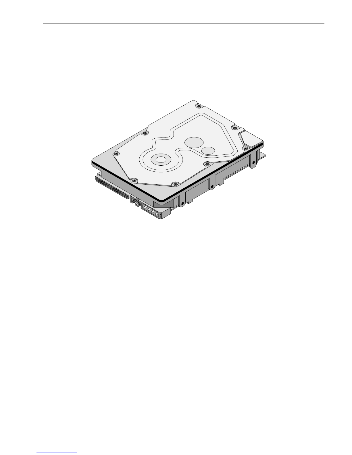
Figure 1. Cheetah X15 family drive (ST318451LW shown) . . . . . . . . . . . . . . . . . . . . . . . . . . . . . . . . . . 1
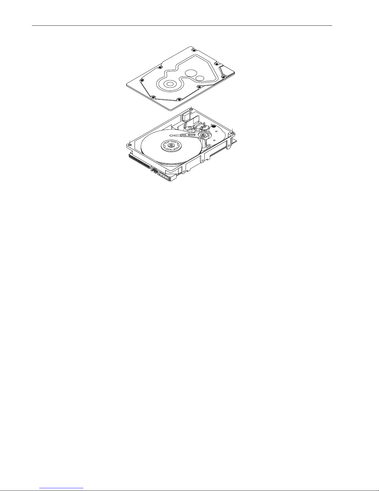
Figure 2. Cheetah X15 family drive (exploded view). . . . . . . . . . . . . . . . . . . . . . . . . . . . . . . . . . . . . . . . 6
Figure 3. Typical ST318451 drive +12 V current profile . . . . . . . . . . . . . . . . . . . . . . . . . . . . . . . . . . . . 23
Figure 4. Typical ST318451 drive +5 V current profile. . . . . . . . . . . . . . . . . . . . . . . . . . . . . . . . . . . . . 23
Figure 5. Typical ST39251 drive +12 V current profile . . . . . . . . . . . . . . . . . . . . . . . . . . . . . . . . . . . . 24
Figure 6. Typical ST39251 drive +5 V cu rrent profile. . . . . . . . . . . . . . . . . . . . . . . . . . . . . . . . . . . . . . 24
Figure 7. ST318451 DC current and power vs. input/output operations per second (SE) . . . . . . . . . . 25
Figure 8. ST318451 DC current and power vs. input/output operations per second (LVD) . . . . . . . . . 25
Figure 9. ST39251 DC current and power vs. input/output operations per second (SE) . . . . . . . . . . . 26
Figure 10. ST39251 DC current and power vs. input/output operations per second (LVD) . . . . . . . . . . 26
Figure 11. Locations of PCBA components listed in Table 4 . . . . . . . . . . . . . . . . . . . . . . . . . . . . . . . . . 28
Figure 12. Recommended mounting . . . . . . . . . . . . . . . . . . . . . . . . . . . . . . . . . . . . . . . . . . . . . . . . . . . . 30
Figure 13. LW mounting configuration dimensions . . . . . . . . . . . . . . . . . . . . . . . . . . . . . . . . . . . . . . . . . 32
Figure 14. LC mounting config uration dimensions . . . . . . . . . . . . . . . . . . . . . . . . . . . . . . . . . . . . . . . . . 33
Figure 15. J6 jumper header . . . . . . . . . . . . . . . . . . . . . . . . . . . . . . . . . . . . . . . . . . . . . . . . . . . . . . . . . . 38
Figure 16. J5 jumper header (on LW models only) . . . . . . . . . . . . . . . . . . . . . . . . . . . . . . . . . . . . . . . . . 39
Figure 17. J2 option select header . . . . . . . . . . . . . . . . . . . . . . . . . . . . . . . . . . . . . . . . . . . . . . . . . . . . . 40
Figure 18. Air flow (suggested) . . . . . . . . . . . . . . . . . . . . . . . . . . . . . . . . . . . . . . . . . . . . . . . . . . . . . . . . 42
Figure 19. LW model drive physical interface (68-pin J1 SCSI I/O connector) . . . . . . . . . . . . . . . . . . . . 55
Figure 20. LC model drive physical interface (80-pin J1 SCSI I/O connector) . . . . . . . . . . . . . . . . . . . . 55
Figure 21. SCSI daisy chain i nterface cabling for LW drives. . . . . . . . . . . . . . . . . . . . . . . . . . . . . . . . . . 59
Figure 22. Nonshielded 68 pin SCSI device connector used on LW drives . . . . . . . . . . . . . . . . . . . . . . 60
Figure 23. Nonshielded 80 pin SCSI “SCA-2” connector, used on LC drives . . . . . . . . . . . . . . . . . . . . . 61
Figure 24. LVD output signals. . . . . . . . . . . . . . . . . . . . . . . . . . . . . . . . . . . . . . . . . . . . . . . . . . . . . . . . . 67
Figure 25. Typical SE-LVD alternative transmitter receiver circuits . . . . . . . . . . . . . . . . . . . . . . . . . . . . 67

Cheetah X15 Product Manual, Rev. C 1
1.0 Scope
This manual describes Seagate Technology®, LLC, Cheetah X15™ disc drives.
Cheetah X15 drives support the small computer system interface (SCSI) as described in the ANSI SCSI SPI-3
interface specifications to the extent described in this manual. The SCSI Interface Product Manual (part number 75789509) describes general SCSI inte rface characteristics of this and other families of Seagate dr ives.
From this point on in this produc t manual the reference to Cheetah X 15 models is referred to as “the d rive”
unless references to individual models are necessary.
Figure 1. Cheetah X15 family dr ive ( S T318451LW shown)

2 Cheetah X15 Product Manual, Rev. C

Cheetah X15 Product Manual, Rev. C 3
2.0 Applicable standards and reference documentation
The drive has been developed as a system peripheral to the highest standards of design and construction. The
drive depends upon its hos t equipment to provide adequate power and environment in order to ach ieve optimum performance and compliance with applicable industry a nd governmental regulations. Special attention
must be given in the areas of safety, power distribution, shielding, audible noise control, and temperature regulation. In particular, the drive must be securely m ount ed in o rder to guarante e the s pecified pe rform ance c haracteristics. Mounting by bottom holes must meet the requirements of Section 8.4.
2.1 Standards
The Cheetah X15 family com pl ies wi th S eagat e st andards as noted in the appropriate sections of this Manual
and the Seagate SCSI Interface Product Manual, part number 75789509 (Vol. 2).
The Cheetah X15 disc drive is a UL recognized component per UL1950, CSA certified to CSA C22.2 No. 950M89, and VDE certified to VDE 0805 and EN 60950 .
2.1.1 Electromagnetic compatibility
The drive, as delivered, is designed for system integration and installation into a suitable enclosure prior to use.
As such the drive is supplied as a subassembly and is not subject to Subpar t B of Part 15 of the FCC Rules
and Regulations nor the Radio Interference Regulations of the Canadian Department of Communications.
The design characteristics of the drive serve to minimize radiation when installed in an enclosure that provides
reasonable shielding. As such, the drive is capable of meeting the Class B limits of the FCC Rules and Regulations of the Canadian Department of Communications when properly packaged. However, it is the user’s
responsibility to assure that the drive meets the appropriate EMI requirements in their system. Shielded I/O
cables may be required if the enclosure does not provide adequate shielding. If the I/O cables are external to
the enclosure, shielded cables should be used, with the shields grounded to the enclosure and to the host controller.
2.1.2 Electromagnetic susceptibility
As a component assem bly, the drive is not required to me et any suscep tibility performance requi remen ts. It is
the responsibility of those integrating the dri ve within their system s to perform t hose t ests req uired and design
their system to ensure that equipment operating in the same system as the drive or external to the system
does not adversely affect the performance of the drive. See Section 5.1.1 and Table 3, DC power requirements.
2.2 Electromagnetic compliance
Seagate uses an independen t laboratory to confirm complia nce to the directives/standard(s) for CE Marking
and C-Tick Marking. The drive was tested in a representative system for typical applications. The selected system represents the most popular characteristics for test platforms. The system configurations include:
• Typical current use microprocessor
• 3.5-inch floppy disc drive
• Keyboard
• Monitor/display
• Printer
• External modem
• Mouse
Although the test system with this Seagate m odel com plies to the directives/standard(s), we cannot guarantee
that all systems will comply. The computer manufacturer or system integrator shall confirm EMC compliance
and provide CE Marking and C-Tick Marking for their product.
Electromagnetic compliance for the European Union
If this model has the CE Marking it complies with the European Union requirements of the Electrom agnetic
Compatibility Directive 89/336/EEC of 03 May 1989 as am ended by Directive 92/31/EEC of 28 A pri l 19 92 and
Directive 93/68/EEC of 22 July 1993.

4 Cheetah X15 Product Manual, Rev. C
Australian C-Ti ck
If this model has the C-Tick Marking it complies with the Au stralia/New Zealand Standard AS/NZS3548 1995
and meets the Electromagnetic Compatibility (EMC) Framework requirements of Australia’s Spectrum Management Agency (SMA).
2.3 Reference documents
Cheetah X15 Installation Guide Seagate P/N 83329485
Safety and Regulatory Agency Specifications Seagate P/N 75789512
SCSI Interface Product Manual Seagate P/N 75789509
Applicabl e ANSI smal l compu ter system interfa ce (SCSI) d ocume nt numb ers:
T10/1143D Enhanced SCSI Parallel Interface (EPI)
T10/1236D Primary Comman ds -2 (SPC-2)
T10/996D SCSI Block Commands (SBC)
T10/1157D SCSI Architectural Model-2 (SAM-2)
T10/1302D SPI-3 (SCSI Parallel Interface version 3)
SFF-8046 Specification for 80-pin connector
Package Test Specification Seagate P/N 30190-001 (under 100 lb.)
Package Test Specification Seagate P/N 30191-001 (over 100 lb.)
Specification, Acoustic Test Requirements, and Procedures Seagate P/N 30553-001
In case of conflict between this document and any referenced document, this document takes precedence.

Cheetah X15 Product Manual, Rev. C 5
3.0 General description
Cheetah X15 drives combine giant magnetoresistive (GMR) heads, partial response/maximum likelihood
(PRML) read channel electronics, embedded servo technology, and a wide Ultra160 SCSI interface to prov ide
high performance, high capacity dat a storage for a variety of systems including engineering workst ations, network servers, mainframes, and supercomputers.
Ultra160 SCSI uses negotiated transfer rates. These transfer rates will occur only if your host adapter supports
these data transfer rates and is compatible with the required hardware requirements of the I/O circuit type. This
drive also operates at SCSI-1 and SCSI-2 data transfer rates for backward compat ibility with non-Ultra/Ultra2/
Ultra160 SCSI host adapters.
Table 1 lists the features that differen tiate the Cheetah X15 m odels.
Table 1: Drive model number vs. differentiating features
[1] See Section 9.6 for details and definitions.
[2] See Section 4.5 for cache details.
The drive records and recovers data on approx imat ely 2.5-i nc h (65 mm) non-removeable discs.
The drive supports the Small Computer System Interface (SCSI) as described in the ANSI SCSI interface
specifications to the extent described in this manual (volume 1), which defines the produc t performance characteristics of the Cheet ah X15 family of drives, and the SCS I Interface Product Manual (volume 2), par t num-
ber 75789509, which describes the general interface characteristics of this and other families of Seagate SCSI
drives.
The drive’s interface supports multiple initiators, disconnect/reconnect, self-configuring host software, and
automatic features that relieve the host from the necessity of knowing the physical characteristics of the targets
(logical block addressing is used).
The head and disc assembly (HDA) is sealed at the factory. Air circulates within the HDA through a nonreplaceable filter to maintain a contamination-free HDA environment.
Refer to Figure 2 for an exploded view of the drive. This exploded view is for information only—never disassemble the HDA and do not attempt to service items in the sealed enclosure (heads, media, actuator, etc.) as this
requires special facilities. The drive contains no replaceable parts. Opening the HDA voids your warranty.
Cheetah X15 dr ives use a dedi cated land ing zone at the inne rm os t radius of the media to eliminate the possibility of destroying or degrading data by landing i n the data zone. The d rive automatically go es to t he landing
zone when power is removed.
An automatic shipping lock prevents potential damage to the heads and discs that results from movement during shipping and handling. The sh ipping lock autom atically diseng ages when power is applied t o the drive and
the head load process begins.
Cheetah X15 drives decode track 0 location data from the servo data embedded on each surface to eliminate
mechanical transducer adjustments and related reliability concer n s.
A high-performance actuator ass embly with a low-inertia, balanced, patented, straight-arm design provides
excellent performance with minimal power dissipation.
Model number
Number
of active
heads
Cache [2]
(kbytes) I/O circ ui t ty p e [1]
Number of I/O
connector pins
Number of I/O
data bus bit s
ST318451LW 10 4,096 Single-ended (SE) and low
voltage differential (LVD)
68 16
ST318451LC
ST39251LC
10 4,096 Single-ended (SE) and low
voltage differential (LVD)
80 16
6 Cheetah X15 Product Manual, Rev. C
Figure 2.
Cheetah X15
family drive (exploded view)

Cheetah X15 Product Manual, Rev. C 7
3.1 Standard features
The Cheetah X15 family has the following standard features:
• Integrated Ultra160 SCSI controller
• Multimode SCSI drivers and receivers—single-ended (SE) and low voltage differential (LV D)
• 16 bit I/O data bus
• Asynchronous and synchronous data transfer protocol (supports Ultra160 transfer rate)
• Firmware downloadable via SCSI interface
• Selectable even by te secto r sizes from 512 to 2,064 bytes/sector
• Programmable sector reallocation scheme
• Flawed sector reallocation at format time
• Programmable auto write and read reallocation
• Reallocation of defects on command (post format)
• ECC maximum burst correction length of 240 bits with a guaranteed burst correction length of 233 bits.
• Sealed head and disc assembly
• No preventative maintenance or adjustment required
• Dedicated head landing zone
• Embedded servo design
• Self diagnostics performed when power is applied to the drive
• Zoned bit recording (ZBR)
• Vertical, horizontal, or top down mounting
• Dynamic spindle brake
• 4,096 kbytes data buffer
• Hot plug compatibility (Section 9.6.4.2 lists proper host connector needed) for LC model drives
• Drive Self Test (DST)
• Supports SCSI bus fairness
3.2 Media characteristics
The media used on the dr ive has an aluminum substrate coated with a thin film magnetic material, overcoated
with a proprietary protective layer for improved durability and environmental protection.
3.3 Performance
• Supports industry standard Ultra160 SCSI interface
• Programmable multi-segmentable cache buffer (see Section 4.5)
• 15k RPM spindle. Average latency = 2.0 ms
• Command queuing of up to 64 commands
• Background processing of queue
• Supports start and stop commands (spindle stops spinning)
3.4 Reliability
• 1,200,000 hour MTBF
• LSI circuitry
• Balanced low mass rotary voice coil actuator
• Incorporates industr y-standa rd Self-Monitori ng, Analysis and Reporting Technol ogy (S.M.A.R.T.)
• 5-year warranty

8 Cheetah X15 Product Manual, Rev. C
3.5 Unformatted a n d formatted capacities
Formatted capacity depends on the number of spare reallocation sectors reserved and the number of bytes per
sector. The following table shows the standard OEM model capacities:
Notes.
[1] Sector size selectable at format time. Users having the necessary equipment may modify the data block
size before issuing a format command and obtain di fferent formatted capacities t han those listed. See
Mode Select Command and Format Command in the SCSI Interface Product Manual.
[2] User available capacity depends on spare reallocation scheme selected, the num ber of data tracks per
sparing zone, and the number of alternate sectors (LBAs) per sparing zone.
3.6 Programmable drive capacity
Using the Mode Select command, the drive can change its capacity to something less than maximum. See the
Mode Select Parameter List table in the SCSI Interface Product Manual. Refer to the Paramete r list block
descriptor number of blocks field. A value of zero in the number of blocks field indicates that the drive shall not
change the capacity it is currently formatted to have. A number in the number of blocks field that is less than
the maximum number o f LBAs chan ges the tot al drive capacity to the value in the block descr iptor number of
blocks field. A va lue greater than the maximum number of LBAs is rounded down to the maximum capacity.
3.7 Factory installed accessories
OEM Standard drives are shipped with the Cheetah X15 Installation Guide, part numbe r 83329485, and the
Safety and Regulatory Agency Specifications, part number 75789512 (unless otherwise specified). The factory
also ships with the drive a small bag of jumper plugs used for the J2, J5, and J6 option select jumper headers.
3.8 Optio ns (factory insta lled)
All customer requested options are in corporated duri ng production or packaged at t he manufacturing facility
before shipping. Some of the options available are (not an exhaustive list of possible options):
• Other capacities can be ordered depending on sparing scheme and secto r size requested.
• Single unit shipping pack. T he drive is nor mally shipped in bulk packaging to provide max imum protection
against transit damage. Units shipped individually require additional protection as provided by the single unit
shipping pack. Users planning single unit distribution should specify this option.
• The Ch eetah X15 Installation Guide, part number 83329485, is usually included with each standard OEM
drive shipped, but extra copies may be ordered.
• The Safety and Regulatory A gency Specifications, part number 75789512, is usually included with each
standard OEM drive shipped, but extra copies may be ordered.
3.9 Accessories (user installed)
The following accessories are available. All accessories may be installed in the field.
• Single unit shipping pack.
Formatted
data block size
512 bytes/sector [1] Unformatted
ST318451 0222EE56h (18.35 GB) [2] 23.86 GB
ST39251 0111772Bh (9.176 GB) [2] 11. 94 GB

Cheetah X15 Product Manual, Rev. C 9
4.0 Performance characteristics
4.1 Internal drive characteristics (transparent to user)
4.2 SCSI performance characteristics (visible to user)
The values given in Section 4.2.1 apply to all models of the Che etah X15 family unless otherwise specified.
Refer to Section 9.10 and to the SCSI Interface Product Manual for additional timing details.
4.2.1 Access time [5]
4.2.2 Format command execution time (minutes) [1]
4.2.3 Generalized performance chara cteris tics
Data buffer transfer rate to/from disc media (one 512-byte sector):
SCSI interface data transfer rate (asynchronous):
Maximum instantaneous one byte wide 5.0 Mbytes/sec [4]
Maximum instantaneous two bytes wide 10.0 Mbytes/sec [4]
Synchronous formatted transfer rate
Ultra2 SCSI Ultra160 SCSI
In low voltage differential (LVD) interface mode 5.0 to 80 Mbytes/sec 5.0 to 160 Mbytes/sec
ST318451 ST39251
Drive capacity 18.35 9.2 GByte (formatted, rounded off values)
Read/write heads 10 6
Bytes/track 176,843 176,843 Bytes (average, rounded off values)
Bytes/surface 1,835 1,835 Mbytes (unformatted, rounded off values)
Tracks/surface (total) 10,377 10,377 Tracks (user accessible)
Tracks/inch 21,400 21,400 TPI
Peak bits/inch 343 343 KBPI
Internal data rate 385-508 385-508 Mbits/sec (variable with zone)
Disc rotational speed 15k 15k r/min
Average rotational latency 2.0 2.0 msec
Including cont roller overhead
(without disconnect) [1] [3]
Not including controller overhead
(without disconnect) [1] [3]
Drive level Drive level
Read Write Read Write
msec msec
Average – Typical [2] 4.1 4.7 3.9 4.5
Single Track – Typical [2] 0.8 1.0 0.5 0.7
Full Stroke – Typical [2] 7.7 8.2 7.5 8.0
ST318451 ST39251
Maximum (with verify) 60 30
Maximum (no verify) 30 15
Minimum sector interleave 1 to 1
Min. [3]* 37.4 MBytes/ se c
Max. [3] 48.9 MBytes/sec

10 Cheetah X15 Product Manual, Rev. C
Sector Sizes:
Default 512 byte user data blocks
Variable 512 to 2,064 bytes per sector in even number of bytes per sector.
If n (number of bytes per sector) is odd, then n-1 will be used.
Notes for Section 4.2.
[1] Execution time measured from receipt of the last byte of the Command Descriptor Block (CDB) to the
request for a Status Byte Transf er to the Initiator (excluding connect/disconnect).
[2] Typical access times are meas ured under nom inal conditions of tempe rature, voltage, and horizontal ori-
entation as measured on a representative sample of drives.
[3] Assumes no errors and no sector has been relocated.
[4] Assumes system ability to support the rates listed and no cable loss.
[5] Access time = controller overhead + average seek time.
Access to data = controller overhead + average seek time + latency time.
4.3 S tar t/stop ti me
After DC power at nominal voltage has been applied, the drive becomes ready within 20 seconds if the Motor
Start Option is disabled (i.e. the motor starts as soon as the power has been applied). If a recoverable error
condition is detected during the star t sequence, the drive executes a recovery procedu re which may cause the
time to become ready to exceed 20 sec onds. During spin up to read y time the drive responds to some c ommands over the SCSI interface in less than 3 seconds after application of power. Stop time is 30 seconds from
removal of DC power.
If the Motor Start Option is enabled, the inter nal controller accept s the commands listed in the S CSI Interface
Product Manual less than 3 seconds after DC power has been applied. After the Motor Start Command has
been received the drive becomes ready for normal operations within 20 seconds typically (excluding an error
recovery procedure). The Motor Start Command can also be used to command the drive to stop the spindle
(see the SCSI Interface Product Manual).
There is no power control switch on the drive.
4.4 Prefetch/multi-segmented cache control
The drive provides prefetch (read look-ahead) and multi-segmented cache control algorithms that in many
cases can enhance system performance. “Cache” as used herein refers to the drive b uffer storage space when
it is used in cache operations. To select prefetch and cache features the host sends the Mode Select command
with the proper values in the applicable bytes in Mode Page 08h (see the SCSI Interface Product Manual).
Prefetch and cache operation are in dependent features from the standpoin t that eac h is enabled and disabled
independently via the Mode Select command. However, in actual operation the prefetch feature overlaps cache
operation somewhat as is noted in Section 4.5.1 and 4.5.2.
All default cache and prefetch Mode parameter values (Mode Page 08h) for standard OEM versions of this
drive family are given in Tables 9.
4.5 Cache operation
In general, 3,600 kbytes of the physical buffer space in the drive can be used as storage space for cache operations. The buffer can be divided into logical segments (Mode S elect Page 08h, byte 13) from which data is
read and to which data is written. The drive supports a maximum of 64 cache segments. The drive maintains a
table of logical block disk medium addresses of the data stored in each segmen t of the buffer. If cache operation is enabled (RCD bit = 0 in Mode Page 08h, byte 2, bit 0. See SCSI Interface Product Manual), data
Read/write consecutive sectors on a track Yes
Flaw reallocation performance impact (for flaws reallocated at format time using
the spare sectors per sparing zone reallocation scheme.)
Negligible
Average rotational latency 2.00 msec

Cheetah X15 Product Manual, Rev. C 11
requested by the host with a Read command is retrieved from the buffer (if it is there), before any disc access
is initiated. If cache operation is not enabled, the buffer (s till segmented with required number of segments) is
still used, but only as circular buffer segments during disc medium read operations (disregarding Prefetch operation for the moment). That is, the drive does not check in the buffer segments for the requested read data, but
goes directly to the medium to retrieve it. The retrieved data merely passes through some buffer segment on
the way to the host. On a cache miss, all data transfers to the host are in accordance with buffer-f ull rat io rules.
On a cache hit the drive ignores the buffer-full ratio rules. See explanations associated with Mode page 02h
(disconnect/reconnect control) in the SCSI Interface Product Manual.
The following is a simplified description of a read operation with cache operation enabled:
Case A -
A Read command is received and the first logical block (LB) is already in cache:
1. Drive transfers to the initiator the first LB requested plus all subsequent contiguous LBs that are alre ady in
the cache. This data may be in multiple segments.
2. When the requested LB is reached that is not in any cache segment, the drive fetches it and any remaining
requested LBs from the disc and puts them in a segment of the cache. The drive transfers the remaining
requested LBs from t he cac he to the host in acco rdance with the disconnect/reconnec t sp ecification mentioned above.
3. If the prefetch feat ure is enabled, refer to Section 4.5.2 for operation from this point.
Case B -
A Read command requests data, the first LB of which is not in any segment of the cache:
1. The drive fetches the requested LBs from the disc and transf ers t hem into a segment, and from there to the
host in accordance with the disconnect/reconnect specification referred to in case A.
2. If the prefetch feat ure is enabled, refer to Section 4.5.2 for operation from this point.
Each buffer segment is actually a self-contained circular storage (wrap-around occurs), the length of which is
an integer number of disc medium sectors. The wrap-around capability of the individual segments greatly
enhances the buffer’s overall performance as a cache storage, allowing a wide range of user selectable config-
urations, which includes their use in the prefetch operation (if enabled), even when cache operation is disabled
(see Section 4.5.2). The number of segments is set dynamically by the drive and cannot be set by the host.
The size in Kbytes of each segment is not reported by the Mode Sense com m and page 08h, bytes 14 and 15.
The value 0XFFFF is always reported. If a size specification is sent by the host in a Mode Select command
(bytes 14 and 15) no new segment size is set up by the drive, and if the STRICT bit in Mode page 00h (byte 2,
bit 1) is set to on e, the drive responds as it doe s for any attempt to change unchangeable pa rameters (see
SCSI Interface Product Manual).
4.5.1 Caching write data
Write caching is a write operation by the drive that makes use of a drive buffer storage area where the data to
be written to the medium is stored in one or more segments while the drive performs the write command.
If read caching is enabled (RCD=0), then data written to the medium is retained in the cache to be made available for future read cache hi ts. The sam e buffer space and segmentation is us ed as set up for read f unct ions.
The buffer se gmentation scheme is set up or changed independently, hav ing nothing to do with the state of
RCD. When a write command is issued, if RCD=0, the cache is first checked to see if any logical blocks that
are to be written are already stored in the cache from a previous read or write command. If there are, the
respective cache segments are cleared. The new data is cached for subsequent Read commands.
If the number of write data logi cal blocks exceeds the size of the segment bei ng written into, when the end of
the segment is reached, the data is written into the beginning of the same cache segment, overwriting the data
that was written there at the beginning of the operation. However, the drive does not overwrite data that has not
yet been written to the medium.
If write caching is enabled (WCE=1), then t he drive may return GOOD status on a wri te command after the
data has been transferred into the cache, but before the data has been written to the medium. If an error occurs
while writing the dat a to the medium, and G OOD status has already been returned, a deferred error will be
generated.

12 Cheetah X15 Product Manual, Rev. C
The Synchronize Cache command may be used to force the drive to write all cached write data to the medium.
Upon completion of a Synchronize Cache command, all data received from previous write commands will have
been written to the medium.
Tables 9 show Mode default settings for the drives.
4.5.2 Prefetch operation
If the Prefetch feature is enabled, data in con tig uous l ogical blocks on the disc immediately beyond that wh ich
was requested by a Read command can be retrieved and stored in the buffer for immediate transfer from the
buffer to the host on subsequent Read commands that request thos e logical blocks (this is tr ue even if cache
operation is disabled). Though the prefetch operation uses the buffer as a cache, finding the requested data in
the buffer is a prefetch hit, not a cache operation hit. Prefetch is enabled using Mode Select page 08h, byte 12,
bit 5 (Disable Read Ahead - DRA bit). DRA bit = 0 enables prefetch. Since data that is prefetched replaces data
already in some buffer segment(s), the host can limit the amount of prefetch data to optimize system performance. The max prefetch field (bytes 8 and 9) limits the amount of prefetch. The drive does not use the
Prefetch Ceiling field (bytes 10 and 11).
During a prefetch operation, the drive crosses a cylinder boundar y t o fetch more data only if the Discontinuity
(DISC) bit is set to one in bit 4 of byte 2 of Mode parameters page 08h.
Whenever prefet ch (read look-ahead) is enabled (enabled by DRA = 0), it operates under the control of ARLA
(Adaptive Read Look-Ahead). If the host uses software interleave, ARLA enables prefetch of contiguous blocks
from the disc when it se nses that a prefetch hit will likely oc cur, even if two consecutive read operations were
not for physically contiguous blocks of data (e.g., “software interleave”). ARLA disables prefetch when it
decides that a prefetch hit will n ot likely oc cur. If the host is not using s oftware inter leave, and if two sequentia l
read operations are not for contiguous blocks of data, ARLA disables prefetch, but as long as sequential read
operations request contiguous blocks of data, ARLA keeps prefetch enabled.

Cheetah X15 Product Manual, Rev. C 13
5.0 Reliability specifications
The following reliability specifications assume correct host/drive operational interface, including all interface
timings, power supply voltages, environmental requirements and drive mounting constraints (see Section 8.4).
Note.
[1] Error rate specified with automatic retries and data correction with ECC enabled and all flaws reallocated.
5.1 Error rates
The error rates stated in this specification assume the following:
• The drive is operated per this specification using DC power as defined in this manual (see Section 6.2).
• The drive has been formatted with the SCSI FORMAT command.
• Errors caused by media defects or host system failures are excluded from error rate computations. Refer to
Section 3.2, “Media Characteristics.”
• Assume random data.
5.1.1 Environmental interference
When evaluating syste ms operation under conditions of Electromagnetic Interference (EMI), the perfor mance
of the drive within the system shall be c onsidered acc eptable if the drive does not generate an unrecoverable
condition.
An unrecoverable error, or unrecoverable condition, is defined as one that:
• Is not detected and corrected by the drive itself;
• Is not capable of being detected from the error or fault status provided through the drive or SCSI interface; or
• Is not capable of being recovered by normal drive or system recovery procedures without operator interven-
tion.
5.1.2 Read errors
Before determination or measurement of read error rates:
• The data that is to be used for measurement of read error rates must be v erifi ed as being written correctly on
the m edia.
• All media defect induced errors must be excluded from error rate calculations.
5.1.3 Write errors
Write errors can occur a s a result of media defects, environmental interference, or equipment malfunction.
Therefore, write errors are not predictable as a function of the number of bits passed.
If an unrecoverable write error occurs because of an equipment malfunction in the drive, the error is classified
as a failure affecting MTBF. Unrecoverable write errors are those which cannot be corrected within two
attempts at writing the record with a read verify after each attempt (exc luding media defects).
5.1.4 Seek errors
A seek error is defined as a failure of the dr ive to posi tion the heads to the addressed track. There shal l be no
more than ten recoverable seek errors in 10
8
physical seek operations. After detecting an initial seek error, the
drive automatically performs an error recovery process. If the error recovery process fails, a seek positioning
Seek Errors
Less than 10 in 10
8
seeks
Read Error Rates [1]
Recovered Data Less than 10 errors in 10
12
bits transferred (OEM default settings)
Unrecovered Data Less than 1 sector in 10
15
bits transferred (OEM default settings)
Miscorrected Data Less than 1 sector in 10
21
bits tran sferred
MTBF 1,200,000 hours
Service Life 5 years
Preventive Maintenance None required

14 Cheetah X15 Product Manual, Rev. C
error (15h) is reported with a Medium error (3h) or Hardware error (4h) reported in the Sense Key. This is an
unrecoverable seek error. Unrecoverable seek errors are classified as failures for MTBF calculations. Refer to
the SCSI Interface Product Manual, part number 75789509, for Request Sense information.
5.2 Reliability and service
You can enhance the r eliabilit y of Cheeta h X15 disc dri ves by ensuring that the dr ive receives adeq uate cooling. Section 6.0 provides temperatu re measurem ents and other i nformation that m ay be used to enha nce the
service life of the drive. Section 8.3.1 prov id es recomm ended air-flow information.
5.2.1 Mean time between failure
The production disc dri ve shall achieve an MTBF of 1,200,000 hours w hen operated in an environment that
ensures the case temperatures specified in Section 6.4.1, T able 4 are not exceeded. Short-term excursions up
to the specification l imits of the operating environment will not affect MTBF performance. Continual or sustained operation at case temperatures above the values shown in Table 4 may degrade product reliability.
The MTBF target is specified as device power-on hours (POH) for all drives in se rvice per failure.
Estimated power-on operating hours in the period = MTBF per measurement period
Number of drive failures in the period
Estimated power-on operation hours means power-up hours per disc drive times the total number of disc drives
in service. Each disc drive shall have accumulated at least nine months of operation. Data shall be calculated
on a rolling average base for a minimum period of six months.
MTBF is based on the following assumptions:
• 8,760 power-on hours per year.
• 250 average on/off cycles per year.
• Operations at nominal voltages.
• Systems will provide adequate cooling to ensure the case tempe ratures specified in Section 6.4.1 are not
exceeded.
Drive failure means any s toppage or substandard performance caused by drive malfunction.
A S.M.A.R.T. predictive failure indicates that the drive is deteriorating to an imminent failure and is considered
an MTBF hit.
5.2.2 Field failure rate vs time
The expected field failure rate is listed below. Drive utilization will vary. An estimated range of utilization is:
• 720 power-on hours (POH) per month.
• 250 on/off cycles per year.
• Read/seek/write operation 20% of power-on hours.
• Systems will provide adequate cooling to ensure the case tempe ratures specified in Section 6.4.1 are not
exceeded.
Failure rate is calculated as follows:
• No system-induced failures are counted
• Based on 1,200,000 MTBF and 720 power-on hours per month
• Month 1’s rate includes a 300 PPM installation fai lure
Month 1 2,364 PPM
Month 2 1,422 PPM
Month 3 1,403 PPM
Month 4 1,391 PPM
Month 5 1,317 PPM
Month 6 1,255 PPM
Month 7 1,162 PPM

Cheetah X15 Product Manual, Rev. C 15
5.2.3 Preventive maintenance
No routine scheduled preventiv e maintenance shall be required.
5.2.4 Service life
The drive shall have a usef ul service life of five years. Depot repair or replacement of major parts is permitted
during the lifetime (see Section 5.2.5).
5.2.5 Servi c e philosophy
Special equipment is required to repair the drive HDA. In order to achieve the above service life, repairs must
be performed only at a proper ly equipped and st affed service and r epair facility. Troubleshooting and repair of
PCBs in the field is not rec ommended, because of the extensive diagnostic equi pment required for effective
servicing. Also, there are no spare parts available for this drive. Drive warranty is voided if the HDA is opened.
5.2.6 Service tools
No special tools are required for site installation or recommended for site maintenance. Refer to Section 5.2.5.
The depot repair philosophy of the drive precludes the necessity for special tools. Field repair of the drive is not
practical since there are no user purchasable parts in the drive.
5.2.7 Hot pl ugg in g C heetah X15 disc drives
The ANSI SPI-3 (T10/13 02D) document defines the physical requirements for removal and inser tion of SCSI
devices on the SCSI bus. Four cases are addressed. The cases are differentiated by the state of the SCSI bus
when the removal or insertion occurs.
Case 1 - All bus devices powered off during removal or insertion
Case 2 - RST signal asserted continuously during removal or insertion
Case 3 - Current I/O processes not allowed during insertion or removal
Case 4 - Current I/O process allowed during insertion or removal, except on the device being changed
Seagate Cheetah X15 d isc dri ves suppor t all four hot plugging c ases. Provision shall be made by the system
such that a device being inserted m akes power and ground connections prior to the conne ction of any device
signal contact to the bus. A device being removed shall maintain power and ground connections after the disconnection of any device signal contact from the bus (see SFF-8046, SCA-2 specification).
It is the responsibility of the systems integrator to assure that no hazards from temperature, energy, voltage, or
ESD potential are presented during the hot connect/disconnect operation.
All I/O processes for the SCSI device being insert ed or removed shall be quiescent. All SCS I devices on the
bus shall have receivers that conform to the SPI-3 standard.
If the device being hot plugged uses single-ended (SE) drivers and the bus is currently operating in low voltage
differential (LVD) mode, then all I/O processes for all devices on the bus must be completed, and the bus quiesced, before attempting to hot plug. Following the insertion of the newly installed device, the SCSI host
adapter must issue a Bus Re set, followed by a synchronous transfer negotiation. Failure to perform the SCSI
Bus Reset could result in erroneous bus operations.
The SCSI bus termination and termination power source shall be external to the device being inserted or
removed.
End users should not mix devices with high voltage differential (HVD) drivers and receivers and devices with
SE, LVD, or multimode drivers and receivers on the same SCSI bus since the common mode voltages in the
HVD environment may not be controlled to safe levels for SE and LVD devices (see ANSI SPI-3).
The disc drive spindle must come to a complete stop prior to completely rem oving the drive from the cabinet
chassis. Use of the Stop Spindle command or partial withdrawal of the drive, enough to be disconnected from
the power source, prior to removal are methods for insuring that this requirement is met. During drive insertion,
care should be taken to avoid exceeding the limits stated in Section 6.4.4, "Shock and vibration" in this manual.

16 Cheetah X15 Product Manual, Rev. C
5.2.8 S.M.A.R.T.
S.M.A.R.T. is an acronym for Self-Monitoring Anal ysis and Re port ing Techn ology. This technology is intended
to recognize conditions that indicate a drive failure and is designed to provide sufficient warning of a failure to
allow data back-up before a n actual failure occurs.
Note.
The firmware will monitor specific attributes for degradation over time but cannot predict instantaneous
drive failures.
Each attribute has been selecte d to m onitor a s pecific s et of failure conditions in th e operating pe rformanc e of
the drive, and the thresholds are optimized to minimize “false” and “failed” predictions.
Controllin g S.M.A.R.T.
The operating mode of S.M.A.R.T. is co ntrol led by t he DEXCPT bit and the PERF bit of the “Informational
Exceptions Control Mode Page” (1Ch). The DEXCPT bit is used to enable or di sable the S.M.A.R.T. process.
Setting the DEXCPT bit will disable all S.M.A.R.T. functions. When enabled, S.M.A.R.T. will collect on-line data
as the drive performs normal read/write operations. When the PERF bit is set, the drive is considered to be in
“On-line Mode Only” and will not perform off-line functions.
The process of measuring off-line attributes and saving data can be forced by the Rezero Unit command. Forcing S.M.A.R.T. will reset the timer so that the next scheduled interrupt will be two hours.
The drive can be interrogated by the host to determine the time remaining before the next scheduled measurement and data logging process will occur. This is accomplished by a log sense command to log page 0x3E.
The purpose is to allow the customer to control when S.M.A.R.T. interruptions occur. As described above, forcing S.M.A.R.T by the Rezero Unit command will reset the timer.
Performance impact
S.M.A.R.T. attribute data will be saved to the disc for the purpose of recreating the events that caused a predictive failure. The drive will measure and s ave parameters once every two hours subject t o an idle period on the
SCSI bus. The process of measuring off-line attribute data and saving data to the disc is uninterruptable and
the maximum delay is summarized below:
Maximum processing delay
On-li ne o nly de l ay F ully en a b le d delay
DEXCPT = 0, PERF = 1 DEXCPT = 0, PERF = 0
S.M.A.R.T. delay times 50 milliseconds 300 millisecond s
Repor tin g c on t rol
Reporting is controlled in the Informational Exce ptions Control Page (1Ch). Sub ject to the repor ting method,
the firmware will issue a 01-5D00 sens e code t o the host. The error code is preser ved through bus resets and
power cycles.
Determining rate
S.M.A.R.T. monitors the rate at which errors occur an d sig nals a predictive failure if the rate of degraded error
rate increases to an unacceptable level. To determine rate, error events are logged and com pared to the num ber of total operations for a gi ven attribute. The interval defines the number of operations over which to measure the rate. The counter that keeps track of the current number of operations is referred to as the Interval
Counter.
S.M.A.R.T. measures error rate, hence for each attribute the occurrence of an error is recorded. A counter
keeps track of the number of errors for the current interval. This counter is referred to as the Failure Counter.
Error rate is simply the number of errors per operation. The algorithm that S.M.A.R.T. uses to record rates of
error is to set thresholds for t he number of errors and the interval. If t he number of errors exceeds the threshold
before the interval expires, then the error rate is considered to be unacceptable. If the number of errors does
not exceed the threshold before the interval expires, then the error rate is considered to be acceptable. In either
case, the interval and failure counters are reset and the process star ts over.
Cheetah X15 Product Manual, Rev. C 17
Predictive failures
S.M.A.R.T. signals predictive failures when the drive is performing unacceptably for a period of tim e. The fir m ware keeps a running count of the number of times the error rate for each attribute is unacceptable. To accomplish this, a counter is incremented whenever the error rate is unacceptable and decremented (not to exceed
zero) whenever the error rate is acceptable. Should the counter continually be incremented such that it reaches
the predictive threshold, a predictive failure is signaled. This counter is referred to as the Failure History
Counter. There is a separate Failure History Counter for each attribute.
5.2.9 Thermal Monitor
Cheetah X15 drives implement a temperature warning system which:
1. Signals the host if the temperature exceeds a value which would threaten the drive.
2. Signals the host if the temperature exceeds a user-specified value.
3. Saves a S.M.A.R.T. data frame on the drive which exceed the threatening temperature value.
A temperature sensor monitors the drive temperature and issue s a warning over the interface when the tem-
perature exceeds a set threshold. The temperature is meas ured at power-up and then at ten-minute inter vals
after power-up.
The therma l monitor system gene rates a warni ng code of 01-0B01 whe n the temperature exceeds the specified limit in compliance with the SCSI standard. The drive temperature is reported in t he FRU code field of
mode sense data. You can use this information to determine if the warning is due to the temperature exceeding
the drive threatening temperature or the user-specified temperature.
This feature is controlled by the Enable Warning (EWasc) bit, and the reporting mechanism is controlled by the
Method of Reporting Informational Exceptions field (MRIE) on the Informational Exceptions Control (IEC)
mode page (1Ch).
The current algorithm implements two temperature trip points. The first trip point is set at 65°C which is the
maximum temperature limit according to the drive specification. The second trip point is user-selectable using
the Log Select command. The reference temperature parameter in the temperature log page (see Table 2) can
be used to set this trip point. The default value for this drive is 65°C, however, you can set it to any value in the
range of 0 to 65°C. If you specify a temperature greater than 65°C in this field, the temperature is rounded
down to 65°C. A sense code is sent to the host to indicate the rounding of the parameter field.
When the first temperature trip point is exceeded, S.M.A.R.T. data is collected and a frame is saved to the disc.
5.2.10 Drive Self Test (DST)
Drive Self Test (DST) is a technology designed to recognize drive fault conditions that qualify the drive as a
failed unit. DST validates the functionality of the drive at a system level.
There are two test coverage options implemented in DST:
1. Extended test
2. Short text
The most thorough option is the extended test that performs various tests on the drive and scans ev ery logical
block address (LBA) of the drive. The short test is time-restricted and limited in length—it does not scan the
entire media surface, but does some fundamental tests and scans portions of the media.
If DST encounters an error during either of these tests, it reports a fault condition. If the drive fails the test,
remove it from service and return it to Seagate for service.
Table 2: Temperature Log page (0Dh)
Parameter Code Description
0000h
Primary Temperature
0001h
Reference Temperature

18 Cheetah X15 Product Manual, Rev. C
5.2.10.1 DST Failure Definition
The drive will present a “diagnostic failed” condition through the self-tests results value of the diagnostic log
page if a functional failure is encountered during DST. The channel and servo parameters are not modified to
test the drive more stringently, and the number of retries are not reduced. All retries and recovery processes
are enabled during the test. If data is recoverable, no failure condition will be reported regardless of the number
of retries required to recover the data.
The following conditions are considered DST fail ure conditions:
• Seek error after retries are exhausted
• Track-follow error after retries are exhausted
• Read error after retries are exhausted
• Write error after retries are exhausted.
Recovered errors will not be reported as diagnostic failures.
5.2.10.2 Implementation
This section provides all of the information necessary to implement the DST function on this drive.
5.2.10.2.1 State of the dr ive prior to testing
The drive must be in a ready state before i s suing the Send Diagnos tic comman d. There are multiple reasons
why a drive may not be ready, some of which are valid conditions, and not errors. For example, a drive may be
in process of doing a format, or another DST . It is the responsibility of the host application to determine the “not
ready” cause.
While not technically part of DST , a Not Ready condition also qualifies the drive to be returned to Seagate as a
failed drive.
A Drive Not Ready condition is reported by the drive under the following conditions:
• Motor w ill not spin
• Motor will not lock to speed
• Servo will not lock on track
• Drive cannot read configuration tables from the disc
In these conditions, the drive responds to a Test Unit Ready comm and with an 02/04/00 or 02/04/03 code.
5.2.10.2.2 Invok ing DST
To invoke DST, submit the Send Diagnostic comma nd with the appropr iate Function Code (001b for the short
test or 010b for the extended test) in bytes 1, bits 5, 6, and 7. Refer to the Seagate SCSI Interface Manual, Volume 3, part number 75789509 for additional information about invoking DST.
5.2.10.2.3 Short and extended tests
DST has two testing options:
1. short
2. extended
These testing options are described in the following two subsections.
Each test consists of three segments: an electrical test segment, a servo test segment, and a read/verify scan
segment.
Short test (Function Code: 001b)
The purpose of the short test is to provide a time-limited test that tests as much of the drive as possible within
120 seconds. The short test does not scan the entire media surface, but does some fundamental tests and
scans portions of the media. A complete read/verify scan is not performed and only factual failures will report a
fault condition. This option provides a quick confidence test of the drive.
Extended test (Function Code: 010b)
The objective of the extended test option is to empirically test critical drive components. For example, the seek
tests and on-track operations test the positioning mechanism. The read operation tests the read head element
 Loading...