


. . . . . . . . . . . . . . . . . . . . . . . . . . . . . . . . . . . . . . . . . . . . . . . . .
Cheetah 18LP Fa mil y :
. . . . . . . . . . . . . . . . . . . . . . . . . . . . . . . . . . . . . . . . . . . . . . . . .
ST318203LW/LWV/LC/LCV
. . . . . . . . . . . . . . . . . . . . . . . . . . . . . . . . . . . . . . . . . . . . . . . . .
ST318233LWV/LCV
. . . . . . . . . . . . . . . . . . . . . . . . . . . . . . . . . . . . . . . . . . . . . . . . .
ST39103LW/LWV/LC/LCV
. . . . . . . . . . . . . . . . . . . . . . . . . . . . . . . . . . . . . . . . . . . . . . . . .
ST39133LWV/LCV
. . . . . . . . . . . . . . . . . . . . . . . . . . . . . . . . . . . . . . . . . . . . . . . . .
Product Manual, Volume 1
. . . . . . . . . . . . . . . . . . . . . . . . . . . . . . . . . . . . . . . . . . . . . . . . .


. . . . . . . . . . . . . . . . . . . . . . . . . . . . . . . . . . . . . . . . . . . . . . . . .
Cheetah 18LP Fa mil y :
. . . . . . . . . . . . . . . . . . . . . . . . . . . . . . . . . . . . . . . . . . . . . . . . .
ST318203LW/LWV/LC/LCV
. . . . . . . . . . . . . . . . . . . . . . . . . . . . . . . . . . . . . . . . . . . . . . . . .
ST318233LWV/LCV
. . . . . . . . . . . . . . . . . . . . . . . . . . . . . . . . . . . . . . . . . . . . . . . . .
ST39103LW/LWV/LC/LCV
. . . . . . . . . . . . . . . . . . . . . . . . . . . . . . . . . . . . . . . . . . . . . . . . .
ST39133LWV/LCV
. . . . . . . . . . . . . . . . . . . . . . . . . . . . . . . . . . . . . . . . . . . . . . . . .
Product Manual, Volume 1
. . . . . . . . . . . . . . . . . . . . . . . . . . . . . . . . . . . . . . . . . . . . . . . . .

© 1998, 1999, 2000 Seagate Technology, Inc. All rights reserved
Publication number: 83329400, Rev. F
February 2000
Seagate, Seagate Technology, and the Seagate logo are registered trademarks of Seagate Tec hnology,
Inc. Cheetah, SeaFAX, SeaFONE, SeaBOARD, and SeaTDD are either trademar ks or registered trademarks of Seagate Technology, Inc. or one of its subsidiaries. All other trademar ks or registered trademarks are the property of their respective owners.
Seagate reserves the right to chang e, without notice, product offerings or specifications. No part of this
publication may be reproduced in any for m without written permission of S eagate Technology, Inc.

Revision status summary sheet
Revision Date Writer/Engineer Sheets Affected
Rev. A 12/01/98 L. Newman/D. Rusch 9, 10, 24, 25, 43,
Rev. B 01/12/99 L. Newman/D. Rusch 7, 33, 45 and 47.
Rev. C 02/19/99 L. Newman/D. Rusch Adds ST39103LW/LC data and rewords
references to the SCSI I/O Manual. Pages
5, 8, 9, 14, 19, 21, 22, 23, 24, 25, 31, 32,
46, 47, 50, 51, 52, 53, 54, 55, 63, and 67.
Rev. D 05/18/99 L. Newman/D. Rusch 14, 19, 23, 24, 32, and 64.
Rev. E 06/15/99 L. Newman/D. Rusch 14, 28, and 30.
Rev. F 2/21/ 2000 L. Newman/G. Velaski 1, 3-5, 7-11, 14, 19-23, 25-29, 31-33,
35-37, 39-41, 45-49, 51-62, 67-69, 71,
and 73-75.
Notice.
Product Manual 83329400 is Volume 1 of a two volume document with the SCSI Interface information in
the Volume 2 SCSI Interface P roduct Manual.
If you need the SCSI Interface information for ST318203 or ST39103 models, order SCSI Interfac e Ma n-
ual, part number 7773 8479. If you need the SCSI Interface information for ST318233 or ST3 9133 models, order SCSI Interface Manual, part number 75789509.


Cheetah 1 8LP Product Manual, Re v. F vii
Table of Contents
1.0 Scope . . . . . . . . . . . . . . . . . . . . . . . . . . . . . . . . . . . . . . . . . . . . . . . . . . . . . . . . . . . . . . . . . . . . . . . . . . 1
2.0 Applicable standards and reference documentation. . . . . . . . . . . . . . . . . . . . . . . . . . . . . . . . . . . . 3
2.1 Standards. . . . . . . . . . . . . . . . . . . . . . . . . . . . . . . . . . . . . . . . . . . . . . . . . . . . . . . . . . . . . . . . . 3
2.1.1 Electromagnetic compatibility . . . . . . . . . . . . . . . . . . . . . . . . . . . . . . . . . . . . . . . . . . 3
2.1.2 Electromagnetic susceptibility. . . . . . . . . . . . . . . . . . . . . . . . . . . . . . . . . . . . . . . . . . 3
2.2 Electromagnetic compliance . . . . . . . . . . . . . . . . . . . . . . . . . . . . . . . . . . . . . . . . . . . . . . . . . . 3
2.3 Reference d ocuments . . . . . . . . . . . . . . . . . . . . . . . . . . . . . . . . . . . . . . . . . . . . . . . . . . . . . . . 4
3.0 General descr iption. . . . . . . . . . . . . . . . . . . . . . . . . . . . . . . . . . . . . . . . . . . . . . . . . . . . . . . . . . . . . . . 5
3.1 Standard features. . . . . . . . . . . . . . . . . . . . . . . . . . . . . . . . . . . . . . . . . . . . . . . . . . . . . . . . . . . 7
3.2 Media characteristics . . . . . . . . . . . . . . . . . . . . . . . . . . . . . . . . . . . . . . . . . . . . . . . . . . . . . . . . 7
3.3 Performance. . . . . . . . . . . . . . . . . . . . . . . . . . . . . . . . . . . . . . . . . . . . . . . . . . . . . . . . . . . . . . . 7
3.4 Reliabili ty . . . . . . . . . . . . . . . . . . . . . . . . . . . . . . . . . . . . . . . . . . . . . . . . . . . . . . . . . . . . . . . . . 7
3.5 Unformatted and formatted capacities . . . . . . . . . . . . . . . . . . . . . . . . . . . . . . . . . . . . . . . . . . . 8
3.6 Programmable drive capacity. . . . . . . . . . . . . . . . . . . . . . . . . . . . . . . . . . . . . . . . . . . . . . . . . . 8
3.7 Factory installed accessories. . . . . . . . . . . . . . . . . . . . . . . . . . . . . . . . . . . . . . . . . . . . . . . . . . 8
3.8 Options (factory installed). . . . . . . . . . . . . . . . . . . . . . . . . . . . . . . . . . . . . . . . . . . . . . . . . . . . . 8
3.9 Accessories (user installed) . . . . . . . . . . . . . . . . . . . . . . . . . . . . . . . . . . . . . . . . . . . . . . . . . . . 8
4.0 Performance characteristics . . . . . . . . . . . . . . . . . . . . . . . . . . . . . . . . . . . . . . . . . . . . . . . . . . . . . . . 9
4.1 Internal drive characteristics (transparent to user). . . . . . . . . . . . . . . . . . . . . . . . . . . . . . . . . . 9
4.2 SCSI performance characte ristics (visible to user) . . . . . . . . . . . . . . . . . . . . . . . . . . . . . . . . . 9
4.2.1 Access tim e . . . . . . . . . . . . . . . . . . . . . . . . . . . . . . . . . . . . . . . . . . . . . . . . . . . . . . . 9
4.2.2 Format comm and ex ecution time (minute s) . . . . . . . . . . . . . . . . . . . . . . . . . . . . . . . 9
4.2.3 Generalized performance characteristics . . . . . . . . . . . . . . . . . . . . . . . . . . . . . . . . . 9
4.3 Start/stop time . . . . . . . . . . . . . . . . . . . . . . . . . . . . . . . . . . . . . . . . . . . . . . . . . . . . . . . . . . . . 10
4.4 Prefetch/m ulti-segmented cache control . . . . . . . . . . . . . . . . . . . . . . . . . . . . . . . . . . . . . . . . 10
4.5 Cache operation. . . . . . . . . . . . . . . . . . . . . . . . . . . . . . . . . . . . . . . . . . . . . . . . . . . . . . . . . . . 10
4.5.1 Caching write data . . . . . . . . . . . . . . . . . . . . . . . . . . . . . . . . . . . . . . . . . . . . . . . . . 11
4.5.2 Prefetch o peration . . . . . . . . . . . . . . . . . . . . . . . . . . . . . . . . . . . . . . . . . . . . . . . . . 12
5.0 Reliability specifications . . . . . . . . . . . . . . . . . . . . . . . . . . . . . . . . . . . . . . . . . . . . . . . . . . . . . . . . . 13
5.1 Error rate s . . . . . . . . . . . . . . . . . . . . . . . . . . . . . . . . . . . . . . . . . . . . . . . . . . . . . . . . . . . . . . . 13
5.1.1 Environmental interference. . . . . . . . . . . . . . . . . . . . . . . . . . . . . . . . . . . . . . . . . . . 13
5.1.2 Read errors. . . . . . . . . . . . . . . . . . . . . . . . . . . . . . . . . . . . . . . . . . . . . . . . . . . . . . . 13
5.1.3 Write erro rs. . . . . . . . . . . . . . . . . . . . . . . . . . . . . . . . . . . . . . . . . . . . . . . . . . . . . . . 13
5.1.4 Seek errors. . . . . . . . . . . . . . . . . . . . . . . . . . . . . . . . . . . . . . . . . . . . . . . . . . . . . . . 13
5.2 Reliability and service . . . . . . . . . . . . . . . . . . . . . . . . . . . . . . . . . . . . . . . . . . . . . . . . . . . . . . . 1 4
5.2.1 Mean time between failure . . . . . . . . . . . . . . . . . . . . . . . . . . . . . . . . . . . . . . . . . . . 14
5.2.2 Field failure rate vs time . . . . . . . . . . . . . . . . . . . . . . . . . . . . . . . . . . . . . . . . . . . . . 14
5.2.3 Preve ntive maintenan ce . . . . . . . . . . . . . . . . . . . . . . . . . . . . . . . . . . . . . . . . . . . . . 15
5.2.4 Service life . . . . . . . . . . . . . . . . . . . . . . . . . . . . . . . . . . . . . . . . . . . . . . . . . . . . . . . 15
5.2.5 Service philosophy . . . . . . . . . . . . . . . . . . . . . . . . . . . . . . . . . . . . . . . . . . . . . . . . . 15
5.2.6 Service tools. . . . . . . . . . . . . . . . . . . . . . . . . . . . . . . . . . . . . . . . . . . . . . . . . . . . . . 15
5.2.7 Hot plugging Cheetah 18LP disc drives . . . . . . . . . . . . . . . . . . . . . . . . . . . . . . . . . 15
5.2.8 S.M.A.R.T. . . . . . . . . . . . . . . . . . . . . . . . . . . . . . . . . . . . . . . . . . . . . . . . . . . . . . . . 16
5.2.9 Product warranty. . . . . . . . . . . . . . . . . . . . . . . . . . . . . . . . . . . . . . . . . . . . . . . . . . . 17
6.0 Physical/electrical specifications . . . . . . . . . . . . . . . . . . . . . . . . . . . . . . . . . . . . . . . . . . . . . . . . . . 19
6.1 AC power requirements . . . . . . . . . . . . . . . . . . . . . . . . . . . . . . . . . . . . . . . . . . . . . . . . . . . . . 1 9
6.2 DC power requirements. . . . . . . . . . . . . . . . . . . . . . . . . . . . . . . . . . . . . . . . . . . . . . . . . . . . . 19
6.2.1 Conduct ed noise immu nity . . . . . . . . . . . . . . . . . . . . . . . . . . . . . . . . . . . . . . . . . . . 20
6.2.2 Power sequenc ing . . . . . . . . . . . . . . . . . . . . . . . . . . . . . . . . . . . . . . . . . . . . . . . . . 20
6.2.3 12 V - Current profile . . . . . . . . . . . . . . . . . . . . . . . . . . . . . . . . . . . . . . . . . . . . . . . 20
6.3 Power dissi pation. . . . . . . . . . . . . . . . . . . . . . . . . . . . . . . . . . . . . . . . . . . . . . . . . . . . . . . . . . 2 3
6.4 Environmental limits. . . . . . . . . . . . . . . . . . . . . . . . . . . . . . . . . . . . . . . . . . . . . . . . . . . . . . . . 27
6.4.1 Temperature. . . . . . . . . . . . . . . . . . . . . . . . . . . . . . . . . . . . . . . . . . . . . . . . . . . . . . 27

viii Cheetah 18LP Product Manual, Rev. F
6.4.2 Relative humidity . . . . . . . . . . . . . . . . . . . . . . . . . . . . . . . . . . . . . . . . . . . . . . . . . . .28
6.4.3 Effective altitude (sea level). . . . . . . . . . . . . . . . . . . . . . . . . . . . . . . . . . . . . . . . . . .28
6.4.4 Shock and vibration. . . . . . . . . . . . . . . . . . . . . . . . . . . . . . . . . . . . . . . . . . . . . . . . .29
6.4.4.1 Shock . . . . . . . . . . . . . . . . . . . . . . . . . . . . . . . . . . . . . . . . . . . . . . . .29
6.4.4.2 Vibration . . . . . . . . . . . . . . . . . . . . . . . . . . . . . . . . . . . . . . . . . . . . . .31
6.4.5 Air cleanliness . . . . . . . . . . . . . . . . . . . . . . . . . . . . . . . . . . . . . . . . . . . . . . . . . . . . .31
6.4.6 Acoustics . . . . . . . . . . . . . . . . . . . . . . . . . . . . . . . . . . . . . . . . . . . . . . . . . . . . . . . . .31
6.4.7 Electromagnetic susceptibility . . . . . . . . . . . . . . . . . . . . . . . . . . . . . . . . . . . . . . . . .31
6.5 Mechanical specifications . . . . . . . . . . . . . . . . . . . . . . . . . . . . . . . . . . . . . . . . . . . . . . . . . . . .32
7.0 Defect and error manageme nt . . . . . . . . . . . . . . . . . . . . . . . . . . . . . . . . . . . . . . . . . . . . . . . . . . . . .35
7.1 Drive inte rnal defects. . . . . . . . . . . . . . . . . . . . . . . . . . . . . . . . . . . . . . . . . . . . . . . . . . . . . . . .35
7.2 Drive erro r recovery procedures . . . . . . . . . . . . . . . . . . . . . . . . . . . . . . . . . . . . . . . . . . . . . . .35
7.3 SCSI systems errors . . . . . . . . . . . . . . . . . . . . . . . . . . . . . . . . . . . . . . . . . . . . . . . . . . . . . . . .36
8.0 Installation . . . . . . . . . . . . . . . . . . . . . . . . . . . . . . . . . . . . . . . . . . . . . . . . . . . . . . . . . . . . . . . . . . . . . 3 7
8.1 Drive ID/option select header . . . . . . . . . . . . . . . . . . . . . . . . . . . . . . . . . . . . . . . . . . . . . . . . .37
8.1.1 Notes for Figures 19, 20, and 21. . . . . . . . . . . . . . . . . . . . . . . . . . . . . . . . . . . . . . .40
8.1.2 Function description. . . . . . . . . . . . . . . . . . . . . . . . . . . . . . . . . . . . . . . . . . . . . . . . .41
8.2 Drive orientation . . . . . . . . . . . . . . . . . . . . . . . . . . . . . . . . . . . . . . . . . . . . . . . . . . . . . . . . . . .42
8.3 Cooling . . . . . . . . . . . . . . . . . . . . . . . . . . . . . . . . . . . . . . . . . . . . . . . . . . . . . . . . . . . . . . . . . .42
8.3.1 Air flow. . . . . . . . . . . . . . . . . . . . . . . . . . . . . . . . . . . . . . . . . . . . . . . . . . . . . . . . . . .42
8.4 Drive mounting . . . . . . . . . . . . . . . . . . . . . . . . . . . . . . . . . . . . . . . . . . . . . . . . . . . . . . . . . . . .43
8.5 Grounding . . . . . . . . . . . . . . . . . . . . . . . . . . . . . . . . . . . . . . . . . . . . . . . . . . . . . . . . . . . . . . . .43
9.0 Interface requiremen ts. . . . . . . . . . . . . . . . . . . . . . . . . . . . . . . . . . . . . . . . . . . . . . . . . . . . . . . . . . . .45
9.1 General description. . . . . . . . . . . . . . . . . . . . . . . . . . . . . . . . . . . . . . . . . . . . . . . . . . . . . . . . .45
9.2 SCSI interface messages supported. . . . . . . . . . . . . . . . . . . . . . . . . . . . . . . . . . . . . . . . . . . .45
9.3 SCSI interface commands suppo rted . . . . . . . . . . . . . . . . . . . . . . . . . . . . . . . . . . . . . . . . . . .46
9.3.1 Inquiry Vital Product data. . . . . . . . . . . . . . . . . . . . . . . . . . . . . . . . . . . . . . . . . . . . .49
9.3.2 Mode Sense data. . . . . . . . . . . . . . . . . . . . . . . . . . . . . . . . . . . . . . . . . . . . . . . . . . .50
9.4 SCSI bus conditions and miscellaneous features support ed . . . . . . . . . . . . . . . . . . . . . . . . .53
9.5 Synchronous data trans fer . . . . . . . . . . . . . . . . . . . . . . . . . . . . . . . . . . . . . . . . . . . . . . . . . . .54
9.5.1 Synch ronous data transfer periods supported. . . . . . . . . . . . . . . . . . . . . . . . . . . . .54
9.5.2 REQ/ACK offset. . . . . . . . . . . . . . . . . . . . . . . . . . . . . . . . . . . . . . . . . . . . . . . . . . . .54
9.6 Physical i nterface . . . . . . . . . . . . . . . . . . . . . . . . . . . . . . . . . . . . . . . . . . . . . . . . . . . . . . . . . .55
9.6.1 DC cable and connector . . . . . . . . . . . . . . . . . . . . . . . . . . . . . . . . . . . . . . . . . . . . .55
9.6.2 SCSI interface physical description . . . . . . . . . . . . . . . . . . . . . . . . . . . . . . . . . . . . .57
9.6.3 SCSI interface cable requirements . . . . . . . . . . . . . . . . . . . . . . . . . . . . . . . . . . . . .58
9.6.4 Mating connectors . . . . . . . . . . . . . . . . . . . . . . . . . . . . . . . . . . . . . . . . . . . . . . . . . .58
9.6.4.1 Ma ting conn ectors for LW and LWV model drives . . . . . . . . . . . . . .58
9.6.4.2 Ma ting conn ectors for LC and LCV model drives. . . . . . . . . . . . . . .59
9.7 Electrical description . . . . . . . . . . . . . . . . . . . . . . . . . . . . . . . . . . . . . . . . . . . . . . . . . . . . . . . .67
9.7.1 Multimo de—SE and LV D alternatives . . . . . . . . . . . . . . . . . . . . . . . . . . . . . . . . . . .67
9.7.1.1 S ingle -ended drivers/recei vers. . . . . . . . . . . . . . . . . . . . . . . . . . . . .69
9.7.1.2 Low v oltage differential I/O circuits. . . . . . . . . . . . . . . . . . . . . . . . . .69
9.7.1.3 General cable characteristics. . . . . . . . . . . . . . . . . . . . . . . . . . . . . .69
9.8 Terminator requirements. . . . . . . . . . . . . . . . . . . . . . . . . . . . . . . . . . . . . . . . . . . . . . . . . . . . .69
9.9 Terminator power . . . . . . . . . . . . . . . . . . . . . . . . . . . . . . . . . . . . . . . . . . . . . . . . . . . . . . . . . .69
9.10 Disc drive SCSI timing. . . . . . . . . . . . . . . . . . . . . . . . . . . . . . . . . . . . . . . . . . . . . . . . . . . . . . .70
9.11 Drive activity LED . . . . . . . . . . . . . . . . . . . . . . . . . . . . . . . . . . . . . . . . . . . . . . . . . . . . . . . . . .71
10.0 Seagate Technology support services. . . . . . . . . . . . . . . . . . . . . . . . . . . . . . . . . . . . . . . . . . . . . . .73

Cheetah 1 8LP Product Manual, Re v. F ix
List of Figures
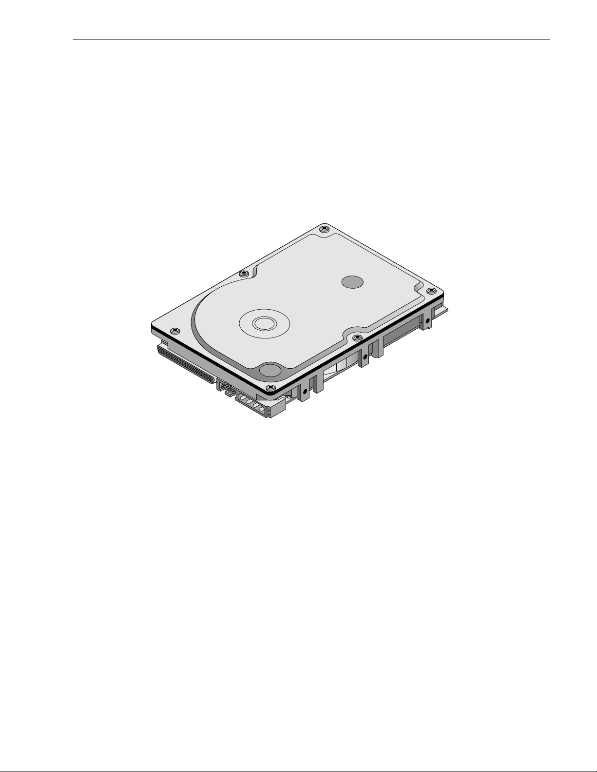
Figure 1. Cheetah 18LP family drive (LW model shown) . . . . . . . . . . . . . . . . . . . . . . . . . . . . . . . . . . . . 1
Figure 2. Cheetah 18LP family drive. . . . . . . . . . . . . . . . . . . . . . . . . . . . . . . . . . . . . . . . . . . . . . . . . . . . 6
Figure 3. Typical ST318203 and ST318233 drive +12 V current profile . . . . . . . . . . . . . . . . . . . . . . . . 21
Figure 4. Typical ST39103 and ST39133 d rive +12 V current profile . . . . . . . . . . . . . . . . . . . . . . . . . . 21
Figure 5. Typical ST318203 and ST318233 dri ve +5 V current profile. . . . . . . . . . . . . . . . . . . . . . . . . 22
Figure 6. Typical ST39103 and ST39133 drive +5 V current profile. . . . . . . . . . . . . . . . . . . . . . . . . . . 22
Figure 7. ST318203 DC current and power vs. input/output operations per second (SE) . . . . . . . . . . 23
Figure 8. ST318203 DC current and power vs. input/output operations per second (LVD) . . . . . . . . . 23
Figure 9. ST39103 DC current and power vs. input/output operations per second (SE) . . . . . . . . . . . 24
Figure 10. ST39103 DC current and power vs. input/output operations per second (LVD) . . . . . . . . . . 24
Figure 11. ST318233 DC current and power vs. input/output operations per second (SE) . . . . . . . . . . 25
Figure 12. ST318233 DC current and power vs. input/output operations per second (LVD) . . . . . . . . . 25
Figure 13. ST39133 DC current and power vs. input/output operations per second (SE) . . . . . . . . . . . 26
Figure 14. ST39133 DC current and power vs. input/output operations per second (LVD) . . . . . . . . . . 26
Figure 15. Locations of PCBA components listed in Tables 3 and 4 . . . . . . . . . . . . . . . . . . . . . . . . . . . . 28
Figure 16. Recommended mounting . . . . . . . . . . . . . . . . . . . . . . . . . . . . . . . . . . . . . . . . . . . . . . . . . . . . 30
Figure 17. LW and LWV mounting configuration dimensions . . . . . . . . . . . . . . . . . . . . . . . . . . . . . . . . . 32
Figure 18. LC and LCV mounting configuration dimensions . . . . . . . . . . . . . . . . . . . . . . . . . . . . . . . . . . 33
Figure 19. J6 jumper header . . . . . . . . . . . . . . . . . . . . . . . . . . . . . . . . . . . . . . . . . . . . . . . . . . . . . . . . . . 38
Figure 20. J5 jumper header (on LW and LWV models only) . . . . . . . . . . . . . . . . . . . . . . . . . . . . . . . . . 39
Figure 21. J2 option select header . . . . . . . . . . . . . . . . . . . . . . . . . . . . . . . . . . . . . . . . . . . . . . . . . . . . . 40
Figure 22. Air flow (suggested) . . . . . . . . . . . . . . . . . . . . . . . . . . . . . . . . . . . . . . . . . . . . . . . . . . . . . . . . 42
Figure 23. LW and LWV model drive physical interface (68-pin J1 SCSI I/O connector) . . . . . . . . . . . . 56
Figure 24. LC and LCV model drive physical interface (80-pin J1 SCSI I/O connector). . . . . . . . . . . . . 56
Figure 25. SCSI daisy chain interface cabling for LW and LWV drives. . . . . . . . . . . . . . . . . . . . . . . . . . 60
Figure 26. Nonshielded 68 pin SCSI device connector used on LW and LWV drives . . . . . . . . . . . . . . 61
Figure 27. Nonshielded 80 pin SCSI “SCA-2” connector, used on LC and LCV drives . . . . . . . . . . . . . 62
Figure 28. LVD output signals. . . . . . . . . . . . . . . . . . . . . . . . . . . . . . . . . . . . . . . . . . . . . . . . . . . . . . . . . 68
Figure 29. Typical SE-LVD alternative transmitter receiver circuits . . . . . . . . . . . . . . . . . . . . . . . . . . . . 68

Cheetah 1 8LP Product Manual, Re v. F 1
1.0 Scope
This manual describes Seagate Technology®, Inc. Cheetah 18LP™ disc drives.
ST318203 and ST3 9103 drives suppor t the s m all c omp uter s ystem in terface (SCSI) as des cribed in the ANSI
SCSI, SCSI-2, and SCSI-3 (Fast-20 and Fast-40) interface specifications to the extent described in this manual. The SCS I I nte rface Product M anual (par t num ber 77738479) descr ibes g eneral S CSI interface characteristics of these Seagate drives.
ST318233 and ST3 9133 drives suppor t the s m all c omp uter s ystem in terface (SCSI) as des cribed in the ANSI
Ultra160 interface specifications to the extent described in this manual. The SCSI Interface Product Manual
(part number 75789509) desc rib es general SCSI interface characteristics of these Seagate drives.
From this point on in this prod uct manual the reference to Cheetah 18LP models is referred to as “the drive”
unless references to individual models are necessary.
Figure 1. Cheetah 18LP family drive (LW model shown)

2 Cheetah 18LP Product Manual, Rev. F

Cheetah 1 8LP Product Manual, Re v. F 3
2.0 Applicable standards and reference documentation
The drive has been developed as a system peripheral to the highest standards of design and construction. The
drive depends upon its hos t equipment to provide adequate power and environment in order to ach ieve optimum performance and compliance with applicable industry a nd governmental regulations. Special attention
must be given in the areas of safety, power distribution, shielding, audible noise control, and temperature regulation. In particular, the drive must be securely m ount ed in o rder to guarante e the s pecified pe rform ance c haracteristics. Mounting by bottom holes must meet the requirements of Section 8.4.
2.1 Standards
ST318203 and ST39103 dr ives comply with Seagate standards as noted in the appropriate sections of this
Manual and the Seagate SCSI Interface Product Manual, part number 77738479.
ST318233 and ST39133 dr ives comply with Seagate standards as noted in the appropriate sections of this
Manual and the Seagate SCSI Interface Product Manual, part number 75789509.
Cheetah 18LP disc dri ves are a UL rec ognized com pone nt per UL1950, CSA certified to CSA C2 2.2 No. 950M89, and VDE certified to VDE 0805 and EN 60950 .
2.1.1 Electromagnetic compatibility
The drive, as delivered, is designed for system integration and installation into a suitable enclosure prior to use.
As such the drive is supplied as a subassembly and is not subject to Subpar t B of Part 15 of the FCC Rules
and Regulations nor the Radio Interference Regulations of the Canadian Department of Communications.
The design characteristics of the drive serve to minimize radiation when installed in an enclosure that provides
reasonable shielding. As such, the drive is capable of meeting the Class B limits of the FCC Rules and Regulations of the Canadian Department of Communications when properly packaged. However, it is the user’s
responsibility to assure that the drive meets the appropriate EMI requirements in their system. Shielded I/O
cables may be required if the enclosure does not provide adequate shielding. If the I/O cables are external to
the enclosure, shielded cables should be used, with the shields grounded to the enclosure and to the host controller.
2.1.2 Electromagnetic susceptibility
As a component assem bly, the drive is not required to me et any suscep tibility performance requi remen ts. It is
the responsibility of those integrating the dri ve within their system s to perform t hose t ests req uired and design
their system to ensure that equipment operating in the same system as the drive or external to the system
does not adversely affect the performance of the drive. See Section 5.1.1 and Table 2, DC power requirements.
2.2 Electromagnetic compliance
Seagate uses an independen t laboratory to confirm complia nce to the directives/standard(s) for CE Marking
and C-Tick Marking. The drive was tested in a representative system for typical applications. The selected system represents the most popular characteristics for test platforms. The system configurations include:
• 486, Pentium, and PowerPC microprocessors
• 3.5-inch floppy disc drive
• Keyboard
• Monitor/display
• Printer
• External modem
• Mouse
Although the test system with this Seagate m odel com plies to the directives/standard(s), we cannot guarantee
that all systems will comply. The computer manufacturer or system integrator shall confirm EMC compliance
and provide CE Marking and C-Tick Marking for their product.
Electromagnetic compliance for the European Union
If this model has the CE Marking it complies with the European Union requirements of the Electrom agnetic
Compatibility Directive 89/336/EEC of 03 May 1989 as am ended by Directive 92/31/EEC of 28 A pri l 19 92 and
Directive 93/68/EEC of 22 July 1993.

4 Cheetah 18LP Product Manual, Rev. F
Australian C-Ti ck
If this model has the C-Tick Marking it complies with the Au stralia/New Zealand Standard AS/NZS3548 1995
and meets the Electromagnetic Compatibility (EMC) Framework requirements of Australia’s Spectrum Management Agency (SMA).
2.3 Reference documents
Cheetah 18LP Installation Guide Seagate P/N 83329410
SCSI Interface Product Manual Seagate P/N 77738479
SCSI Interface Product Manual (Ultra160 and later) Seagate P/N 75789509
ANSI small computer system interface (SCSI) document numbers:
X3.131-1994 SCSI-2
X3.253-1995 SCSI-3 Parallel Interface
T10/1142D Rev. 14 SPI-2 (SCSI-3 Parallel Interface version 2)
SFF-8046 Specification for 80-pin connector for SCSI disk drives
Package Test Specification Seagate P/N 30190-001 (under 100 lb.)
Package Test Specification Seagate P/N 30191-001 (over 100 lb.)
Specification, Acoustic Test Requirements, and Procedures Seagate P/N 30553-001
In case of conflict between this document and any referenced document, this document takes precedence.

Cheetah 1 8LP Product Manual, Re v. F 5
3.0 General description
Cheetah 18LP drives combine dual stripe magnetoresistive (DSMR) heads, partial response/max imum likelihood (PRML) read channel electronics, embedded servo technology, and a wide Ultra2 (Ultra160 on
ST318233 and ST39133 mode ls) SCSI interface to provide high performance, high capacity data storage for a
variety of systems including engineering workstations, network servers, mainframes, and supercomputers.
The SCSI interface uses negotiated transfer rates. These transfer rates will occur only if your host adapter supports these da ta transfer rates and is compatible with the required hardware requ irements of the I/O circuit
type. This drive also operates at SCSI-1 and SCSI-2 data transfer rates for backward compatibility with nonUltra/Ultra2/Ultra160 SCSI host adapters.
Table 1 lists the features that differentiate the two Cheetah 18LP models.
Table 1: Drive model number vs. differentiating features
Number
Model number
of active
heads I/O circuit type [1]
Numbe r o f I/O
connector pins
Number of I/O
data bus bit s SCSI interface
ST318203LW/LWV
ST39103LW/LWV126
Single-ended (SE)
and low voltage
68 16 Ultra2
differential (LVD)
ST318203LC/LCV
ST39103LC/LCV
12
6
Single-ended (SE)
and low voltage
80 16 Ultra2
differential (LVD)
ST318233LWV
ST39133LWV
12
6
Single-ended (SE)
and low voltage
68 16 Ultra160
differential (LVD)
ST318233LCV
ST39133LCV
12
6
Single-ended (SE)
and low voltage
80 16 Ultra160
differential (LVD)
[1] See Section 9.6 for details and definitions.
The drive records and recovers data on approxim ately 3.3-inc h (84 mm) non-removable discs.
ST318203 and ST39103 model drives suppor t the Small Computer System Interface (SCSI) as described in
the ANSI SCSI interface specifications to the extent described in this manual, which defines the product performance characteristics of these drives, and the SC SI Interface Product Manual, part numb er 77738479, wh ich
describes the general interface characteristics of these drives.
ST318233 and ST39133 model drives suppor t the Small Computer System Interface (SCSI) as described in
the ANSI SCSI interface specifications to the extent described in this manual, which defines the product performance characteristics of these drives, and the SC SI Interface Product Manual, part numb er 75789509, wh ich
describes the general interface characteristics of these drives.
The drive’s interface supports multiple initiators, disconnect/reconnect, self-configuring host software, and
automatic features that relieve the host from the necessity of knowing the physical characteristics of the targets
(logical block addressing is used).
The head and disc assembly (HDA) is sealed at the factory. Air circulates within the HDA through a nonreplaceable filter to maintain a contamination-free HDA environment.
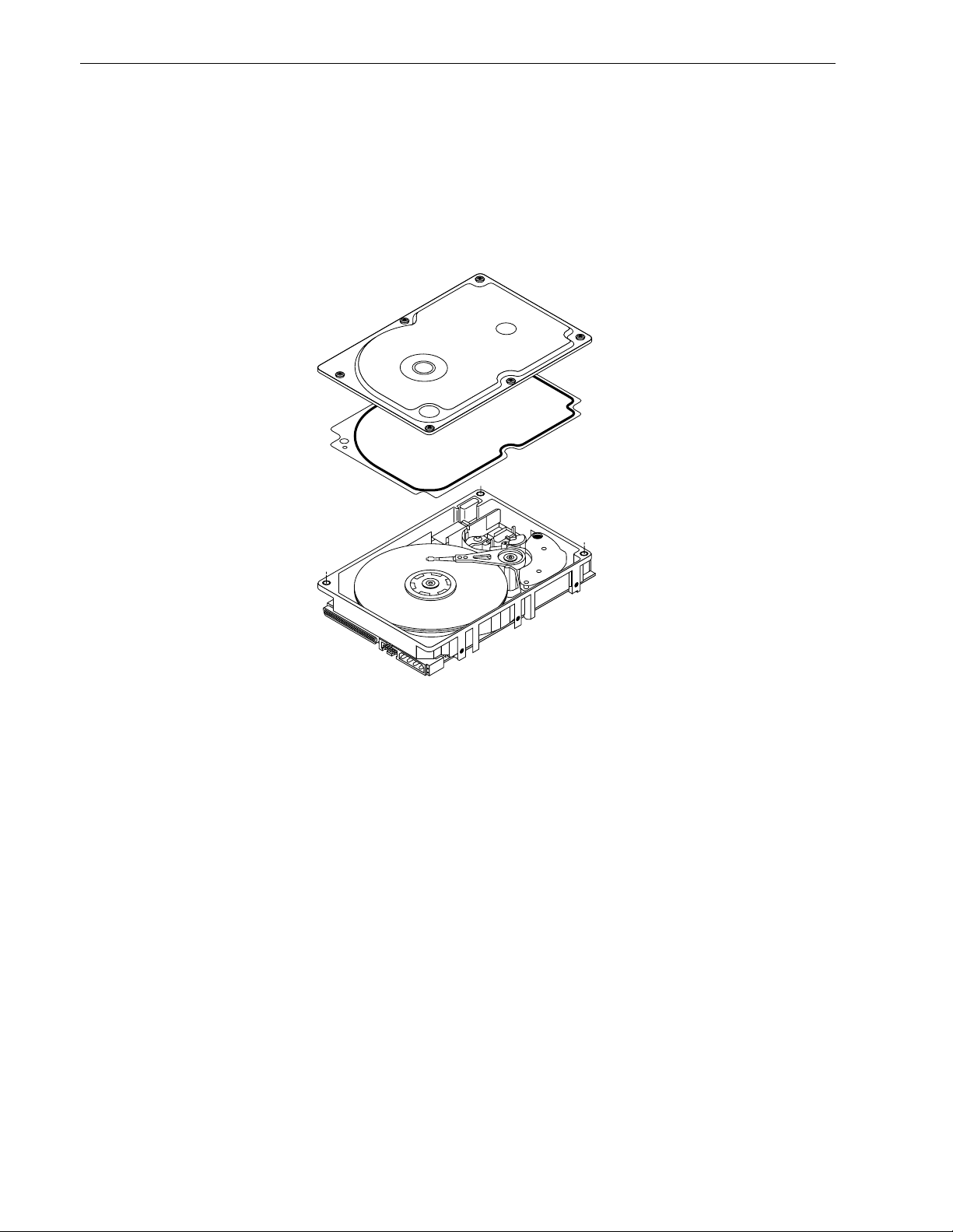
Refer to Figure 2 for an exploded view of the drive. This exploded view is for information only—never disassemble the HDA and do not attempt to service items in the sealed enclosure (heads, media, actuator, etc.) as this
requires special facilities. The drive contains no replaceable parts. Opening the HDA voids your warranty.
Cheetah 18LP drives use a dedicated landing zone at the innermost radius of the media to eliminate the possibility of destroying or degrading data by landing i n the data zone. The d rive automatically go es to t he landing
zone when power is removed.
6 Cheetah 18LP Product Manual, Rev. F
An automatic shipping lock prevents potential damage to the heads and discs that results from movement during shipping and handling. The sh ipping lock autom atically diseng ages when power is applied t o the drive and
the head load process begins.
Cheetah 18LP drives decode track 0 location data from the servo data embedded on each surface to eliminate
mechanical transducer adjustments and related reliability concerns.
A high-performance actuator ass embly with a low-inertia, balanced, patented, straight-arm design provides
excellent performance with minimal power dissipation.
Figure 2.
Cheetah 18LP
family drive

Cheetah 1 8LP Product Manual, Re v. F 7
3.1 Standard features
The Cheetah 18LP family has the following standard features:
• Integrated Ultra/Ultra2 SCSI controller (ST318203 and ST39103 models)
• Integrated Ultra160 SCSI controller (ST318233 and ST39133 models)
• Multimode SCSI drivers and receivers—single-ended (SE) and low voltage differential (LVD )
• 16 bit I/O data bus
• Asynchronous and synchronous data transfer protocol
• Firmware downloadable via SCSI interface
• Selectable even by te secto r sizes from 512 to 4,096 bytes/sector
• Programmable sector reallocation scheme
• Flawed sector reallocation at format time
• Programmable auto write and read reallocation
• Reallocation of defects on command (post format)
• Enhanced ECC correction capability up to 185 bits
• Sealed head and disc assembly
• No preventative maintenance or adjustment required
• Dedicated head landing zone
• Embedded servo design
• Self diagnostics performed when power is applied to the drive
• 1:1 Interleave
• Zoned bit recording (ZBR)
• Vertical, horizontal, or top down mounting
• Dynamic spindle brake
• 1,024 kbyte data buffer (4 , 096 kbytes on LWV/LCV models)
• Hot plug compatibility (Section 9.6.4.2 lists proper host connector needed) for “LC” and “LCV” model drives
• SCAM (SCSI Configured Automatically) plug-n-play level 2 compliant, factory set to level 1
3.2 Media characteristics
The media used on the drive has a diameter of approximately 3.3 inches (84 mm). The aluminum substrate is
coated with a thin film magnet ic materi al, overcoated with a proprie tary prot ective layer for improved dura bilit y
and environmental protection.
3.3 Performance
• Supports industry standard Ultra2 SCSI interface (ST318203 and ST39103 models)
• Supports industry standard Ultra160 SCSI interface (ST318233 and ST39133 models)
• Programmable multi-segmentable cache buffer (see Section 3.1)
• 10,016 RPM spindle. Average latency = 2.99 ms
• Command queuing of up to 64 commands
• Background processing of queue
• Supports start and stop commands (spindle stops spinning)
3.4 Reliability
• 1,000,000 hour MTBF
• LSI circuitry
• Balanced low mass rotary voice coil actuator
• Incorporates industr y-standa rd Self-Monitori ng, Analysis and Reporting Technol ogy (S.M.A.R.T.)
• 5-year warranty

8 Cheetah 18LP Product Manual, Rev. F
3.5 Unformatted a n d formatted capacities
Formatted capacity depends on the number of spare reallocation sectors reserved and the number of bytes per
sector. The following table shows the standard OEM model capacities:
Formatted
data block size
512 bytes/sector [1] Unformatted
ST318203 and ST318233 21EB390h (18.20 GB) [2] 21.6 GB
ST39103 and ST39133 10F59C8h (9.10 GB) [2] 10. 8 GB
Notes.
[1] Sector size selectable at format time. Users having the necessary equipment may modify the data block
size before issuing a format command and obtain di fferent formatted capacities t han those listed. See
Mode Select Command and Format Command in the appropriate SCSI Interface Product Manual.
[2] User available capacity depends on spare reallocation scheme selected, the number of data tracks per
sparing zone, and the number of alternate sectors (LBAs) per sparing zone.
3.6 Programmable drive capacity
Using the Mode Select command, the drive can change its capacity to something less than maximum. See the
Mode Select Parameter List table in the appropriate SCSI Interface Product Manual. Refer to the Parameter li st
block descriptor number of blocks field. A value of zero in the number of blocks field indicates that the drive
shall not change the c apacity it is currently format ted to have. A number in the number o f blocks field that is
less than the max imum number of LB As changes th e total drive capacity to the value in the block descr iptor
number of blocks field. A value greater than the m aximum number of LB As is rou nded down to the maximum
capacity.
3.7 Factory installed accessories
OEM Standard drives are shipped with the Cheetah 18LP Installation Guid e, part number 83329410 (unless
otherwise specified). The factory also ships with the drive a small bag of jumper plug s used for the J2, J5, and
J6 option select jumper headers.
3.8 Optio ns (factory insta lled)
All customer requested options are in corporated duri ng production or packaged at t he manufacturing facility
before shipping. Some of the options available are (not an exhaustive list of possible options):
• Other capacities can be ordered depending on sparing scheme and secto r size requested.
• Single unit shipping pack. T he drive is nor mally shipped in bulk packaging to provide max imum protection
against transit damage. Units shipped individually require additional protection as provided by the single unit
shipping pack. Users planning single unit distribution should specify this option.
• The Cheetah 18LP Installation Gu ide, par t number 8332941 0, is usually include d with each standard OEM
drive shipped, but extra copies may be ordered.
3.9 Accessories (user installed)
The following accessories are available. All accessories may be installed in the field.
• Single unit shipping pack.

Cheetah 1 8LP Product Manual, Re v. F 9
4.0 Performance characteristics
4.1 Internal drive characteristics (transparent to user)
ST318203 ST39103 ST318233 ST39133
Drive capacity 18.2 9.10 18.2 9.10 GByte (formatted, rounded)
Read/write heads 12 6 12 6
Bytes/track 153,284–
229,045
Bytes/surface 1,913 1,913 1,913 1,913 Mbytes (unformatted, rounded)
Tracks/surface (total) 9,801 9,801 9,801 9,801 Tracks (user accessible)
Tracks/inch 12,580 12,580 12,580 12,580 TPI
Peak bits/inch 2 52 252 252 252 K BPI
Internal data rate 193-308 193–308 193-308 193–308 Mbits/sec (variable with zone)
Disc rotational speed 10,016 10,016 10,016 10,016 r/min (+
Average rotational latency 2.99 2.99 2.99 2.99 msec
4.2 SCSI performance characteristics (visible to user)
The values given in Section 4.2.1 apply to all models of the Cheetah 18LP family unless otherwise specified.
Refer to Section 9.10 and to the appropriate SCSI Interface Product Manual, for additional timing details.
153,284–
229,045
153,284–
229,045
153,284–
229,045
Bytes (average, rounded)
0.5%)
4.2.1 Access time [5]
Including cont roller overhead
(without disconnect) [1] [3]
Drive level Drive level
Not including controller overhead
(without disconnect) [1] [3]
Read Write R ead Write
msec msec
Average – Typical [2] 5.4 6.0 5.2 5.8
Single Track – Typical [2] 0.7 0.9 0.5 0.7
Full Stroke – Typical [2] 12.2 13.2 12.0 13.0
4.2.2 Format command execution time (minutes) [1]
ST318203/ST318233 ST39103/ST39133
Maximum (with verify) 60 60
Maximum (no verify) 30 30
4.2.3 Generalized performance chara cteris tics
Minimum sector interleave 1 to 1
Data buffer transfer rate to/from disc media (one 512-byte sector):
Min. [3] 22.7 MByte/sec
Avg. [3] 29.5 MB yte/ s ec
Max. [3] 36.2 MByte/sec
SCSI interface data transfer rate (asynchronous):
Maximum instantaneous one byte wide 5.0 Mbytes/sec [4]
Maximum instantaneous two bytes wide 10.0 Mbytes/sec [4]
Synchronous transfer rate for SCSI Fast-40, Ultra2 SCSI (ST318203 and ST39103 models):
In single-ended (SE) interface mode 5.0 to 40 Mbytes/sec
In low voltage differential (LVD) interface mode 5.0 to 80 Mbytes/sec

10 Cheetah 18LP Product Manual, Rev. F
Synchronous transfer rate for Ultra160 SCSI (ST318233 and ST39133 models):
In single-ended (SE) interface mode 5.0 to 40 Mbytes/sec
In low voltage differential (LVD) interface mode 5.0 to 160 Mbytes/sec
Sector Sizes:
Default 512 byte user data blocks
Variable 512 to 4,096 bytes per sector in even number of bytes per sector.
If n (number of bytes per sector) is odd, then n-1 will be used.
Read/write consecutive sectors on a track Yes
Flaw reallocation performance impact (for flaws reallocated at format time using
Negligible
the spare sectors per sparing zone reallocation scheme.)
Average rotational latency 2.99 msec
Notes for Section 4.2.
[1] Execution time measured from receipt of t he last byte of the Command Descrip tor Block (CDB) to the
request for a Status Byte Transf er to the Initiator (excluding connect/disconnect).
[2] Typical access times are m easured und er nominal conditions of temperature, voltage, and horizontal ori-
entation as measured on a representative sample of drives.
[3] Assumes no errors and no sector has been relocated.
[4] Assumes system ability to support the rates listed and no cable loss.
[5] Access time = controller overhead + average seek time.
Access to data = controller overhead + average seek time + latency time.
4.3 S tar t/stop ti me
After DC power at nominal voltage has been applied, the drive becomes ready within 30 seconds if the Motor
Start Option is disabled (i.e. the motor starts as soon as the power has been applied). If a recoverable error
condition is detected during the star t sequence, the drive executes a recovery procedu re which may cause the
time to become ready to exceed 30 sec onds. During spin up to read y time the drive responds to some c ommands over the SCSI interface in less than 3 seconds after application of power. Stop time is less than 30 seconds from removal of DC power.
If the Motor Start Option is enabled, the inter nal controller accept s the commands listed in the S CSI Interface
Product Manual less than 3 seconds after DC power has been applied. After the Motor Start Command has
been received the drive becomes ready for normal operations within 30 seconds typically (excluding an error
recovery procedure). The Motor Start Command can also be used to command the drive to stop the spindle
(see the appropriate SCSI Interface Product Manual).
There is no power control switch on the drive.
4.4 Prefetch/multi-segmented cache control
The drive provides prefetch (read look-ahead) and multi-segmented cache control algorithms that in many
cases can enhance system performance. “Cache” as used herein refers to the drive b uffer storage space when
it is used in cache operations. To select prefetch and cache features the host sends the Mode Select command
with the proper values in the applicable bytes in Mode Page 08h (see the appropr iate SCS I Interface Product
Manual). Prefetch and cache ope ration are independe nt features from the standpoin t that each is enabled and
disabled independently via the Mode S el ect com m and. However, in actual operation the prefetch feature overlaps cache operation somewhat as is noted in Section 4.5.1 and 4.5.2.
All default cache and prefetch Mode parameter values (Mode Page 08h) for standard OEM versions of this
drive family are given in Tables 9.
4.5 Cache operation
In general, 840 Kbytes (3,600 kbytes of the 4,096 kbytes on LWV and LCV units) of the physical buffer space in
the drive can be used as storage space for cache operations. The buffer c an be divided into logical segments
(Mode Select Page 08h, byte 13) from which data is read and to which data is written. The drive maintains a

Cheetah 1 8LP Product Manual, Re v. F 11
table of logical block disk medium addresses of the data stored in each segmen t of the buffer. If cache operation is enabled (RCD bit = 0 in Mode Page 08h, byte 2, bit 0. See the appropriate SCSI Interface Product Man-
ual), data requested by the host with a Read command is retrieved from the buffer (if it is there), before any disc
access is initiated. If cache operation is not enabled, the buffer (still segmented with required number of segments) is still used, but only as circular buffer segment s during disc medium read operations (disregarding
Prefetch operation for the moment). That is, the drive does not check in the buffer segments for the requested
read data, but goes directly to the medium to retrieve it. The retrieved dat a merel y passes through some buffer
segment on the way to the host. On a cache miss, all data transfers to the host are in accordance with bufferfull ratio rules. On a cache hit the drive ignores the buffer-full ratio rules. See explanations assoc iated with
Mode page 02h (disconnect/reconnect control) in the appropriate SCSI Interface Product Manual.
The following is a simplified description of a read operation with cache operation enabled:
Case A -
A Read command is received and the first logical block (LB) is already in cache:
1. Drive transfers to the initiator the first LB requested plus all subsequent contiguous LBs that are alre ady in
the cache. This data may be in multiple segments.
2. When the requested LB is reached that is not in any cache segment, the drive fetches it and any remaining
requested LBs from the disc and puts them in a segment of the cache. The drive transfers the remaining
requested LBs from t he cac he to the host in acco rdance with the disconnect/reconnec t sp ecification mentioned above.
3. If the prefetch feat ure is enabled, refer to Section 4.5.2 for operation from this point.
Case B -
A Read command requests data, the first LB of which is not in any segment of the cache:
1. The drive fetches the requested LBs from the disc and transf ers t hem into a segment, and from there to the
host in accordance with the disconnect/reconnect specification referred to in case A.
2. If the prefetch feat ure is enabled, refer to Section 4.5.2 for operation from this point.
Each buffer segment is actually a self-contained circular storage (wrap-around occurs), the length of which is
an integer number of disc medium sectors. The wrap-around capability of the individual segments greatly
enhances the buffer’s overall performance as a cache storage, allowing a wide range of user selectable config-
urations, which includes their use in the prefetch operation (if enabled), even when cache operation is disabled
(see Section 4.5.2). The number of segm ents may be selected using the Mode Select comm and, but the size
can not be directly selected. Size is selected only as a by-product of selecting the segment number specification. The size in Kbytes of each segment is not reported by the Mode Sense command page 08h, bytes 14 and
15. The value 0XFFFF is always reported. If a size specification is sent by the host in a Mode Select command
(bytes 14 and 15) no new segment size is set up by the drive, and if the STRICT bit in Mode page 00h (byte 2,
bit 1) is set to one, the drive responds as it does for any attempt to change unchangeable parameters (see the
appropriate SCSI Interface Product Manual). The dri ve supports operation of any integer number o f segm ent s
from 1 to 16. Default is three segments.
4.5.1 Caching write data
Write caching is a write operation by the drive that makes use of a drive buffer storage area where the data to
be written to the medium is stored in one or more segments while the drive performs the write command.
If read caching is enabled (RCD=0), then data written to the medium is retained in the cache to be made available for future read cache hi ts. The sam e buffer space and segmentation is us ed as set up for read f unct ions.
The buffer se gmentation scheme is set up or changed independently, hav ing nothing to do with the state of
RCD. When a write command is issued, if RCD=0, the cache is first checked to see if any logical blocks that
are to be written are already stored in the cache from a previous read or write command. If there are, the
respective cache segments are cleared. The new data is cached for subsequent Read commands.
If the number of write data logi cal blocks exceeds the size of the segment bei ng written into, when the end of
the segment is reached, the data is written into the beginning of the same cache segment, overwriting the data
that was written there at the beginning of the operation. However, the drive does not overwrite data that has not
yet been written to the medium.
If write caching is enabled (WCE=1), then t he drive may return GOOD status on a wri te command after the
data has been transferred into the cache, but before the data has been written to the medium. If an error occurs

12 Cheetah 18LP Product Manual, Rev. F
while writing the dat a to the medium, and G OOD status has already been returned, a deferred error will be
generated.
The Synchronize Cache command may be used to force the drive to write all cached write data to the medium.
Upon completion of a Synchronize Cache command, all data received from previous write commands will have
been written to the medium.
Tables 9 show Mode default settings for the drives.
4.5.2 Prefetch operation
If the Prefetch feature is enabled, data in con tig uous l ogical blocks on the disc immediately beyond that wh ich
was requested by a Read command can be retrieved and stored in the buffer for immediate transfer from the
buffer to the host on subsequent Read commands that request thos e logical blocks (this is tr ue even if cache
operation is disabled). Though the prefetch operation uses the buffer as a cache, finding the requested data in
the buffer is a prefetch hit, not a cache operation hit. Prefetch is enabled using Mode Select page 08h, byte 12,
bit 5 (Disable Read Ahead - DRA bit). DRA bit = 0 enables prefetch. Since data that is prefetched replaces data
already in some buffer segment(s), the host can limit the amount of prefetch data to optimize system performance. The max prefetch field (bytes 8 and 9) limits the amount of prefetch. The drive does not use the
Prefetch Ceiling field (bytes 10 and 11).
During a prefetch operation, the drive crosses a cylinder boundar y t o fetch more data only if the Discontinuity
(DISC) bit is set to one in bit 4 of byte 2 of Mode parameters page 08h.
Whenever prefet ch (read look-ahead) is enabled (enabled by DRA = 0), it operates under the control of ARLA
(Adaptive Read Look-Ahead). If the host uses software interleave, ARLA enables prefetch of contiguous blocks
from the disc when it se nses that a prefetch hit will likely oc cur, even if two consecutive read operations were
not for physically contiguous blocks of data (e.g., “software interleave”). ARLA disables prefetch when it
decides that a prefetch hit will n ot likely oc cur. If the host is not using s oftware inter leave, and if two sequentia l
read operations are not for contiguous blocks of data, ARLA disables prefetch, but as long as sequential read
operations request contiguous blocks of data, ARLA keeps prefetch enabled.

Cheetah 1 8LP Product Manual, Re v. F 13
5.0 Reliability specifications
The following reliability specifications assume correct host/drive operational interface, including all interface
timings, power supply voltages, environmental requirements and drive mounting constraints (see Section 8.4).
Seek Errors
Less than 10 in 10
Read Error Rates [1]
Recovered Data Less than 10 errors in 10
Unrecovered Data Less than 1 sector in 10
Miscorrected Data Less than 1 sector in 10
MTBF 1,000,000 hours
Service Life 5 years
Preventive Maintenance None required
Note.
[1] Error rate specified with automatic retries and data correction with ECC enabled and all flaws reallocated.
5.1 Error rates
The error rates stated in this specification assume the following:
• The drive is operated per this specification using DC power as defined in this manual (see Section 6.2).
• The drive has been formatted with the SCSI Format command.
• Errors caused by media defects or host system failures are excluded from error rate computations. Refer to
Section 3.2, “Media Characteristics.”
• Assume random data.
8
seeks
12
bits transferred (OEM default settings)
15
bits transferred (OEM default settings)
21
bits transferred
5.1.1 Environmental interference
When evaluating syste ms operation under conditions of Electromagnetic Interference (EMI), the perfor mance
of the drive within the system shall be c onsidered acc eptable if the drive does not generate an unrecoverable
condition.
An unrecoverable error, or unrecoverable condition, is defined as one that:
• Is not detected and corrected by the drive itself;
• Is not capable of being detected from the error or fault status provided through the drive or SCSI interface; or
• Is not capable of being recovered by normal drive or system recovery procedures without operator interven-
tion.
5.1.2 Read errors
Before determination or measurement of read error rates:
• The data that is to be used for measurement of read error rates must be v erifi ed as being written correctly on
the m edia.
• All media defect induced errors must be excluded from error rate calculations.
5.1.3 Write errors
Write errors can occur a s a result of media defects, environmental interference, or equipment malfunction.
Therefore, write errors are not predictable as a function of the number of bits passed.
If an unrecoverable write error occurs because of an equipment malfunction in the drive, the error is classified
as a failure affecting MTBF. Unrecoverable write errors are those which cannot be corrected within two
attempts at writing the record with a read verify after each attempt (exc luding media defects).
5.1.4 Seek errors
A seek error is defined as a failure of the dr ive to posi tion the heads to the addressed track. There shal l be no
more than ten recoverable seek errors in 10
8
physical seek operations. After detecting an initial seek error, the
drive automatically performs an error recovery process. If the error recovery process fails, a seek positioning
error (15h) is reported with a Medium error (3h) or Hardware error (4h) reported in the Sense Key. This is an

14 Cheetah 18LP Product Manual, Rev. F
unrecoverable seek error. Unrecoverable seek errors are classified as failures for MTBF calculations. Refer to
the appropriate SCSI Interface Product Manual, for Request Sense information.
5.2 Reliability and service
You can enhance the reliability of Cheetah 18LP disc drives by ensuring that the drive receives adequate cooling. Section 6.0 provides temperatu re measurem ents and other i nformation that m ay be used to enha nce the
service life of the drive. Section 8.3.1 prov id es recomm ended air-flow information.
5.2.1 Mean time between failure
The production disc dri ve shall achieve an MTBF of 1,000,000 hours w hen operated in an environment that
ensures the case temperatures specified in Section 6.4.1, T able 3 are not exceeded. Short-term excursions up
to the specification l imits of the operating environment will not affect MTBF performance. Continual or sustained operation at case temperatures above the values shown in Table 3 may degrade product reliability.
The MTBF target is specified as device power-on hours (POH) for all drives in se rvice per failure.
Estimated power-on operating hours in the period
MTBF per measurement period =
Number of drive failures in the period
Estimated power-on operation hours means power-up hours per disc drive times the total number of disc drives
in service. Each disc drive shall have accumulated at least nine months of operation. Data shall be calculated
on a rolling average base for a minimum period of six months.
MTBF is based on the following assumptions:
• 8,760 power-on hours per year.
• 250 average on/off cycles per year.
• Operations at nominal voltages.
• Systems will provide adequate cooling to ensure the case tempe ratures specified in Section 6.4.1 are not
exceeded.
Drive failure means any stoppage or failure to meet defined specifications caused by drive malfunction.
A S.M.A.R.T. predictive failure indicates that the drive is deteriorating to an imminent failure and is considered
an MTBF hit.
5.2.2 Field failure rate vs time
The expected field failure rate is listed below. Drive utilization will vary. An estimated range of utilization is:
• 720 power-on hours (POH) per month.
• 250 on/off cycles per year.
• Read/seek/write operation 20% of power-on hours.
• Systems will provide adequate cooling to ensure the case tempe ratures specified in Section 6.4.1 are not
exceeded.
Month 1 2,364 PPM
Month 2 1,422 PPM
Month 3 1,403 PPM
Month 4 1,391 PPM
Month 5 1,317 PPM
Month 6 1,255 PPM
Month 7 1,162 PPM
Month 8+ 1,025 PPM
Failure rate is calculated as follows:
• No system-induced failures are counted
• Based on 1,000,000 MTBF and 720 power-on hours per month
• Month 1’s rate includes a 300 PPM installation fai lure

Cheetah 1 8LP Product Manual, Re v. F 15
5.2.3 Preventive maintenance
No routine scheduled preventiv e maintenance shall be required.
5.2.4 Service life
The drive shall have a usef ul service life of five years. Depot repair or replacement of major parts is permitted
during the lifetime (see Section 5.2.5).
5.2.5 Servi c e philosophy
Special equipment is required to repair the drive HDA. In order to achieve the above service life, repairs must
be performed only at a proper ly equipped and st affed service and r epair facility. Troubleshooting and repair of
PCBs in the field is not rec ommended, because of the extensive diagnostic equi pment required for effective
servicing. Also, there are no spare parts available for this drive. Drive warranty is voided if the HDA is opened.
5.2.6 Service tools
No special tools are required for site installation or recommended for site maintenance. Refer to Section 5.2.5.
The depot repair philosophy of the drive precludes the necessity for special tools. Field repair of the drive is not
practical since there are no user purchasable parts in the drive.
5.2.7 Hot plugging Chee ta h 1 8LP di s c dri v es
The ANSI SPI-2 (T10/1142D) docum ent defines the physical requirements for removal and insertion of SCSI
devices on the SCSI bus. Four cases are addressed. The cases are differentiated by the state of the SCSI bus
when the removal or insertion occurs.
Case 1 - All bus devices powered off during removal or insertion
Case 2 - RST signal asserted continuously during removal or insertion
Case 3 - Current I/O processes not allowed during insertion or removal
Case 4 - Current I/O process allowed during insertion or removal, except on the device being changed
Seagate Cheetah 18LP disc d rives support all four hot plugging cases. Provision shall be made by the system
such that a device being inserted m akes power and ground connections prior to the conne ction of any device
signal contact to the bus. A device being removed shall maintain power and ground connections after the disconnection of any device signal contact from the bus (see SFF-8046, SCA-2 specification).
It is the responsibility of the systems integrator to assure that no hazards from temperature, energy, voltage, or
ESD potential are presented during the hot connect/disconnect operation.
All I/O processes for the SCSI device being insert ed or removed shall be quiescent. All SCS I devices on the
bus shall have receivers that conform to the SPI-2 standard.
If the device being hot plugged uses single-ended (SE) drivers and the bus is currently operating in low voltage
differential (LVD) mode, then all I/O processes for all devices on the bus must be completed, and the bus quiesced, before attempting to hot plug. Following the insertion of the newly installed device, the SCSI host
adapter must issue a Bus Re set, followed by a synchronous transfer negotiation. Failure to perform the SCSI
Bus Reset could result in erroneous bus operations.
The SCSI bus termination and termination power source shall be external to the device being inserted or
removed.
End users should not mix devices with high voltage differential (HVD) drivers and receivers and devices with
SE, LVD, or multimode drivers and receivers on the same SCSI bus since the common mode voltages in the
HVD environment may not be controlled to safe levels for SE and LVD devices (see ANSI SPI-2).
The disc drive spindle must come to a complete stop prior to completely rem oving the drive from the cabinet
chassis. Use of the Stop Spindle command or partial withdrawal of the drive, enough to be disconnected from
the power source, prior to removal are methods for insuring that this requirement is met. During drive insertion,
care should be taken to avoid exceeding the limits stated in Section 6.4.4, "Shock and vibration" in this manual.

16 Cheetah 18LP Product Manual, Rev. F
5.2.8 S.M.A.R.T.
S.M.A.R.T. is an acronym for Self-Monitoring Anal ysis and Re port ing Techn ology. This technology is intended
to recognize conditions that indicate a drive failure and is designed to provide sufficient warning of a failure to
allow data back-up before a n actual failure occurs.
Note.
The firmware will monitor specific attributes for degradation over time but cannot predict instantaneous
drive failures.
Each attribute has been selecte d to m onitor a s pecific s et of failure conditions in th e operating pe rformanc e of
the drive, and the thresholds are optimized to minimize “false” and “failed” predictions.
Controllin g S.M.A.R.T.
The operating mode of S.M.A.R.T. is co ntrol led by t he DEXCPT bit and the PERF bit of the “Informational
Exceptions Control Mode Page” (1Ch). The DEXCPT bit is used to enable or di sable the S.M.A.R.T. process.
Setting the DEXCPT bit will disable all S.M.A.R.T. functions. When enabled, S.M.A.R.T. will collect on-line data
as the drive performs normal read/write operations. When the PERF bit is set, the drive is considered to be in
“On-line Mode Only” and will not perform off-line functions.
The process of measuring of f-line attributes and saving data can be forced by the RTZ command. Forcing
S.M.A.R.T. will reset the timer so that the next scheduled interrupt will be two hours.
The drive can be interrogated by the host to determine the time remaining before the next scheduled measurement and data logging process will occur. This is accomplished by a log sense command to log page 0x3E.
The purpose is to allow the customer to control when S.M.A.R.T. interruptions occur. As described above, forcing S.M.A.R.T by the Rezero Unit command will reset the timer.
Performance impact
S.M.A.R.T. attribute data will be saved to the disc for the purpose of recreating the events that caused a predictive failure. The drive will measure and s ave parameters once every two hours subject t o an idle period on the
SCSI bus. The process of measuring off-line attribute data and saving data to the disc is uninterruptable and
the maximum delay is summarized below:
Maximum processing delay
On-li ne o nly de l ay Fully enabled de lay
DEXCPT = 0, PERF = 1 DEXCPT = 0, PERF = 0
S.M.A.R.T. delay times 50 milliseconds 300 milliseconds
Repor tin g c on t rol
Reporting is controlled in the Informational Exce ptions Control Page (1Ch). Sub ject to the repor ting method,
the firmware will issue a 01-5D00 sens e code t o the host. The error code is preser ved through bus resets and
power cycles.
Determining rate
S.M.A.R.T. monitors the rate at which errors occur an d sig nals a predictive failure if the rate of degraded error
rate increases to an unacceptable level. To determine rate, error events are logged and com pared to the num ber of total operations for a gi ven attribute. The interval defines the number of operations over which to measure the rate. The counter that keeps track of the current number of operations is referred to as the Interval
Counter.
S.M.A.R.T. measures error rate, hence for each attribute the occurrence of an error is recorded. A counter
keeps track of the number of errors for the current interval. This counter is referred to as the Failure Counter.
Error rate is simply the number of errors per operation. The algorithm that S.M.A.R.T. uses t o record rates of
error is to set thresholds for t he number of errors and the interval. If t he number of errors exceeds the threshold
before the interval expires, then the error rate is considered to be unacceptable. If the number of errors does
not exceed the threshold before the interval expires, then the error rate is considered to be acceptable. In either
case, the interval and failure counters are reset and the process star ts over.

Cheetah 1 8LP Product Manual, Re v. F 17
Predictive failures
S.M.A.R.T. signals predictive failures when the drive is performing unacceptably for a period of tim e. The fir m ware keeps a running count of the number of times the error rate for each attribute is unacceptable. To accomplish this, a counter is incremented whenever the error rate is unacceptable and decremented (not to exceed
zero) whenever the error rate is acceptable. Should the counter continually be incremented such that it reaches
the predictive threshold, a predictive failure is signaled. This counter is referred to as the Failure History
Counter. There is a separate Failure History Counter for each attribute.
5.2.9 Product warranty
Beginning on the date of shipment to customer and continuing for a period of five years, Seagate warrants that
each product (including components and subassemblies) or spare part that fails to function properly under normal use due to defect in materials on workmanship or due to nonconformance to the applicable specifications
will be repaired or replaced, at Seagate ’s option and at no charge to customer, if returned by customer at customer’s expense to Seagate’s designated facility in accordance with Seagate’s warranty procedure. Seagate
will pay for transporting the rep air or replacement item to customer. For more detailed warranty information
refer to the Standard terms and condition s of Purchase for Seagate products.
Shipping
When transpor ting or shipping a drive, a Seagate approved containe r must be used. Keep your original box.
They are easily identified by the Seagate-approved package label. Shipping a drive in a non-approved c ontainer voids the drive warranty .
Seagate repair centers may refuse recei pt of compon ent s im properly packaged or obviously damage d in transit. Contact your Authorized Seagate Distributor to purchase additional boxes. Seagate recommends s hipping
by an air-ride carrier experienced in handling computer equipment.
Product repair and re turn information
Seagate customer service centers are the only facilities authorized to service Seagate drives. Seagate does
not sanction any third-party repair facilities. Any unauthorized repair or tampering with the factory-seal voids
the warranty.

18 Cheetah 18LP Product Manual, Rev. F
Cheetah 1 8LP Product Manual, Re v. F 19
6.0 Physical/electrical specifications
This section provides information relating to th e physical and electrical characteristics of the Cheetah 18LP
drive.
6.1 AC power requirem ents
None.
6.2 DC power requirements
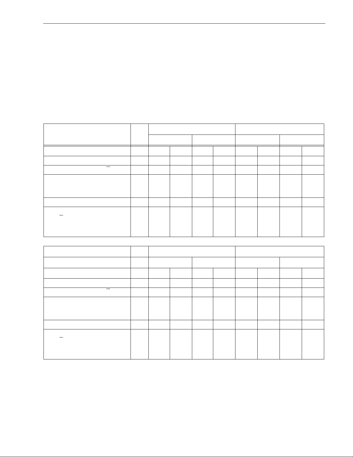
The voltage and current requirements for a single drive are shown in the following table. Values indicated apply
at the drive power connector. The table shows current values in Amperes.
T able 2: DC power requirements
Notes
SE mode LVD mode SE mode LVD mode
ST318203 ST39103
Voltage +5V +12 V +5V +12 V +5 V +12 V +5 V +12 V
Regulation [5] ±5% ±5%[2] ±5% ±5%[2] ±5% ±5%[2] ±5% ±5%[2]
Average idle current DCX
[1][7] 0.69 0.6 0.71 0.6 0.71 0.34 0.72 0.34
Maximum starting current
(peak DC) DC
(peak AC) AC
[3]
[3]
0.79
1.0
1.53
2.4
0.81
1.03
1.53
2.4
0.81
0.94
1.4
2.2
0.82
0.95
1.4
2.2
Delayed motor start (max) DC [1][4] 0.61 0 .02 0.62 0.02 0.62 0.02 0.65 0.02
Peak operating current
DCX
Maximum DC
Maximum (peak) DC
[1][6]
[1]
0.76
0.79
1.05
1.03
1.13
2.66
SE mode LVD mode SE mode LVD mode
0.82
0.84
1.27
ST318233 ST39133
1.03
1.13
2.66
0.79
0.80
1.06
0.81
0.84
2.2
0.84
0.85
1.27
0.81
0.84
2.2
Voltage +5V +12 V +5V +12 V +5 V +12 V +5 V +12 V
Regulation [5] ±5% ±5%[2] ±5% ±5%[2] ±5% ±5%[2] ±5% ±5%[2]
Average idle current DCX
[1][7] 0.8 0.65 0.88 0.65 0.8 0.45 0. 88 0.45
Maximum starting current
(peak DC) DC
(peak AC) AC
[3]
[3]
0.82
1.1
1.61
3.1
0.90
1.13
1.61
3.1
0.81
1.1
1.71
3.1
0.89
1.12
1.71
3.1
Delayed motor start (max) DC [1][4] 0.67 0.04 0.76 0.04 0. 67 0.04 0.76 0.04
Peak operating current
DCX
Maximum DC
Maximum (peak) DC
[1][6]
[1]
0.82
0.83
0.91
1.09
1.13
2.4
0.92
0.93
1.18
1.09
1.13
2.4
0.82
0.83
0.95
0.88
0.98
2.24
0.92
0.93
1.19
0.88
0.98
2.24
[1] Measured with average reading DC ammeter or equivalent sampl ing scop e. Instantaneo us c urrent peak s
will exceed these values. Power supply at nominal voltage. N = 6, 22 Degrees C ambient.
[2] For +12 V, a –10% tolerance is perm issible during initial start o f spindle, and must return to ±5% before
10,000 rpm is reached. The ±5% must be maintained after the drive signifies that its power-up sequence
has been completed and that the drive is able to accept selection by the host initiator.
[3] See +12 V current profile in Figure 3.
[4] This condition occurs when the Motor Star t Option is enabled and the drive has not yet received a Start
Motor co mm a n d.
[5] See Section 6.2.1 “Conducte d Noise Immunity.” Specified voltage tolerance is inclusive of ripple, noise,
and transient response.

20 Cheetah 18LP Product Manual, Rev. F
[6] Operating condition is defined as random 8 block reads at 200 I/Os per second for ST318203 drive, 203 I/
Os per second for ST39103 drives, and 197 I/Os per second for ST318233 and ST39133 drives. Current
and power specified at nominal voltages. ST318203 and ST39103: Increasin g +5 volts by +5% increas es
5 volt current by < 0.5%. ST318233 and ST39133: Decreasing +5 volts by +5% increases 5 volt current by
2.7%. All Cheetah 18LP models: Decreasing +12 volt supply by 5% increases 12 volt current by 1.4%.
[7] During idle, the drive heads are re located every 60 seconds to a random loca tion within the band from
track zero to one-fourth of maximum track.
General Notes for Table 2:
1. Minimum current loading for each supp ly voltage is not le ss than 1. 9% of the m aximum operating current
shown.
2. The +5 and +12 volt supplies shall employ separate ground returns.
3. Where power is provided to multiple drives from a common supply, careful consideration for individual drive
power requirements should be noted. Where multiple units are powered on simultaneously, the peak starting current must be available to each device.
4. Parameters, other than spindle start, are measured after a 10-minute warm up.
5. No ter m inator power.
6.2.1 Conducted noise immunity
Noise is specified as a per iodic and random distri bution of frequencies covering a band from DC to 10 MHz.
Maximum allowed noise values given below are peak to peak measurements and apply at the drive power connector.
+5 V = 150 mV pp from 0 to 100 kHz and 100 mV pp from 100 kHz to 10 MHz.
+12 V = 150 mV pp from 0 to 100 kHz and 100 mV pp from 100 kHz to 10 MHz.
6.2.2 Power sequencing
The drive does not req uire power sequenc ing. The d rive protects against inadvertent writing d uring power-up
and down. Daisy-chain operation requires that power be maintained on the SC SI bus terminator to ensure
proper termination of the peripheral I/O cables. To automatically delay motor start based on the target ID (SCSI
ID) enable the Delay Motor Start option and disable the Enable Motor Start option on the J2 connector. See
Section 8.1 for pin selection information. To delay the motor until the drive receives a Star t Unit command,
enable the Enable Remote Motor Start option on the J2 connector.
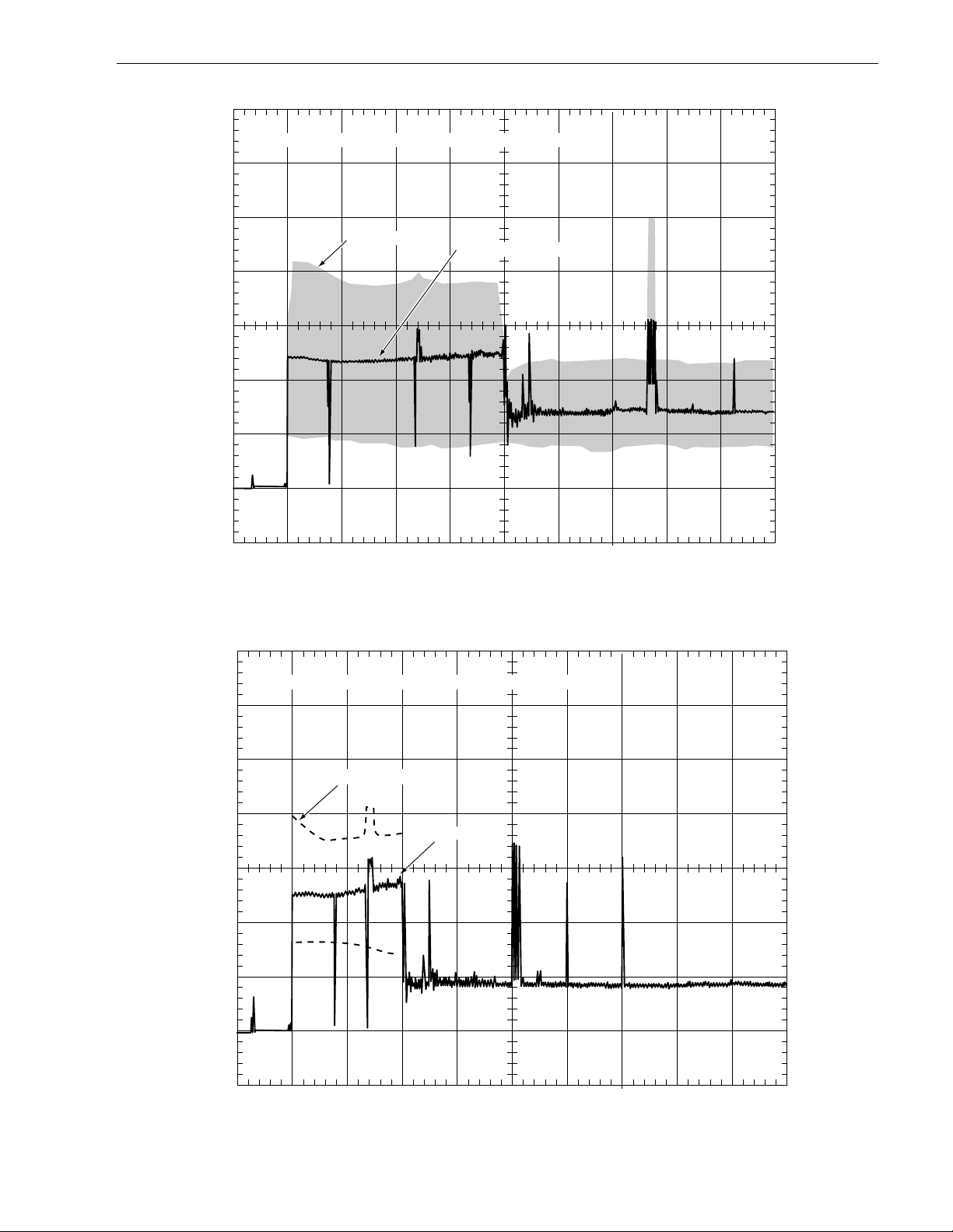
6.2.3 12 V - Current profile
Figures 3 and 4 identify t h e drive +12 V current profiles of drives doc um ente d in this m anual. The current during the various times is as shown:
T0 - Power is applied to the drive.
T1 - Controller self tests are pe rformed.
T2 - Spi ndle begins to accelerate under current limiting after performing drive internal
diagnostics. See Note 1 of T able 2.
T3 - The spindle is up to speed and the head-arm restraint is unlocked.
T4 - The adaptive servo calibration sequence is performed.
T5 - Ca libration is complete and drive is ready for reading and writing.
Note.
All times and currents are typical. See Table 2 for maximum current requirements.
Cheetah 1 8LP Product Manual, Re v. F 21
+12 Volt Current during spindle start – Typical Amperes
2.5
AC Envelope
2.0
A
1.5
1.0
0.5
0.0
T0 T1 T3 T4
T2
DC (average) of waveform
0.0 2 4 6 8 10 12 14 16
Seconds
Figure 3. Typical ST318203 and ST318233 drive +12 V curr ent profile
+12 Volt Current during spindle start – Typical Amperes
2.5
Peak AC Envelope
2.0
Peak DC
1.5
A
1.0
0.5
0
T0 T1 T3 T4
T2
0.0 2 4 6 8 10 12 14 16
Seconds
Figure 4. T ypical ST39103 and ST39133 drive +12 V current profile

22 Cheetah 18LP Product Manual, Rev. F
+5 Volt Current during spindle start – Typical Amperes
+5V
Current
(amps)
1.0
0.5
A
Nominal (average) DC curve
0
T0
T1
T2
T4
T3 T5
AC
Component
0.0 4 8 12 16 20 24 28 32
Seconds
Figure 5. Typical ST318203 and ST318233 drive +5 V current profile
+5 Volt Current during spindle start – Typical Amperes
+5V
Current
(amps)
1.0
A
0.5
AC
Component
Nominal (average) DC curve
0
T2
T1T0 T3 T5
T4
0.0 2 4 6 8 10 12 14 16
Seconds
Figure 6. Typical ST39103 and ST39133 drive +5 V curr ent profile

Cheetah 1 8LP Product Manual, Re v. F 23
6.3 Power dissipation ST318203
For drives using single-ended interface circuits, typical power dissipation under idle conditions i s 10.65 watts
(36.3 BTUs per hour).
For drives using low voltage differential interface circuits, typical power dissipation under idle conditions is
10.75 watts (36.7 BTUs per hour).
To obtain operating power for typical random read operations, refer to the following I/O rate curves. Locate the
typical I/O rate for a drive in y our system on the horizontal axis and read the corresponding +5 volt current, +12
volt current, and total watts on the vertical axis. To calculate BTUs per hour, multiply watts by 3.4123.
1.8
5V A
1.6
1.4
12V A
Watts
1.2
1
Amperes
0.8
0.6
0.4
0 50 100
I/Os per Second
150 200 250
Figure 7. ST318203 DC current and power vs. input /output operations per second (SE)
1.8
1.6
1.4
1.2
17
15
Watts
13
11
5V A
12V A
Watts
17
1
Amperes
0.8
0.6
0.4
0 50 100
150 200 250
I/Os per Second
15
13
11
Figure 8. ST318203 DC current and power vs. input /output operations per second (LVD)
Watts

24 Cheetah 18LP Product Manual, Rev. F
ST39103
For drives using single-ended interface circuits, t ypical power di ssipation under idle conditions is 7.63 watts (26
BTUs per hour).
For drives using low voltage differential interface circuits, typical power dissipation under idle conditions is 7.68
watts (26.2 BTUs per hour).
To obtain operating power for typical random read operations, refer to the following two I/O rate curves (see
Figures 9 and 10). Locate the typical I/O rate for a drive in your system on the horizontal axis and read the corresponding +5 volt current, +12 volt current, and total watts on the vertical axis. To calculate BTUs per hour,
multiply watts by 3.4123.
1.600
1.400
1.200
5V A
12V A
Watts
1.000
0.800
Amperes
0.600
0.400
0.200
0 50 100
I/Os per Second
Figure 9. ST39103 DC current and power vs. input/output operations per second (SE)
150 200 250
1.600
1.400
1.200
1.000
15
13
Watts
11
9
7
5V A
12V A
Watts
15
0.800
Amperes
0.600
0.400
0.200
0 50 100
150 200 250
I/Os per Second
Figure 10. ST39103 DC current and power vs. input /output operations per second (LVD)
13
Watts
11
9
7

Cheetah 1 8LP Product Manual, Re v. F 25
ST318233
For drives using single-ended interface circuits, typical power dissipation under idle conditions is 11.8 watts
(40.27 BTUs per hour).
For drives using low voltage differential interface circuits, typical power dissipation under idle conditions is 12.2
watts (41.63 BTUs per hour).
To obtain operating power for typical random read operations, refer to the following two I/O rate curves (see
Figures 7 and 8). Locate the typical I/O rate for a drive in your system on the horizontal axis and read the corresponding +5 volt current, +12 volt current, and total watts on the vertical axis. To calculate BTUs per hour,
multiply watts by 3.4123.
1.6
1.4
5V A
22
12V A
Watts
1.2
1.0
0.8
Amperes
0.6
0.4
0.2
0 50 100
I/Os per Second
Figure 11. ST318233 DC current and power vs. input/output operations per second (SE)
1.6
1.4
1.2
150 200 250
20
18
16
14
12
22
20
Watts
5V A
12V A
Watts
1.0
0.8
Amperes
0.6
0.4
0.2
0 50 100
I/Os per Second
Figure 12. ST318233 DC current and power vs. input/output operations per second (LVD)
150 200 250
18
16
14
12
Watts

26 Cheetah 18LP Product Manual, Rev. F
ST39133
For drives using single-ended interface circuits, typical power dissipation under idle c ondi tions is 9.4 watts (32
BTUs per hour).
For drives using low voltage differential interface circuits, typical power dissipation under idle conditions is 9.8
watts (33.4 BTUs per hour).
To obtain operating power for typical random read operations, refer to the following two I/O rate curves (see
Figures 7 and 8). Locate the typical I/O rate for a drive in your system on the horizontal axis and read the corresponding +5 volt current, +12 volt current, and total watts on the vertical axis. To calculate BTUs per hour,
multiply watts by 3.4123.
1.6
1.4
5V A
22
12V A
Watts
1.2
1.0
0.8
Amperes
0.6
0.4
0.2
0 50 100
I/Os per Second
Figure 13. ST39133 DC current and power vs. input /output operations per second (SE)
1.6
1.4
1.2
150 200 250
20
18
16
14
12
22
20
Watts
5V A
12V A
Watts
1.0
0.8
Amperes
0.6
0.4
0.2
0 50 100
I/Os per Second
Figure 14. ST39133 DC current and power vs. input /output operations per second (LVD)
150 200 250
18
16
Watts
14
12

Cheetah 1 8LP Product Manual, Re v. F 27
6.4 Environment al limits
Temperature and humi dity values experienced by the drive must be s uch th at con densat ion do es not oc cur on
any drive part. Altitude and atmospheric pressu re specifications are referenced to a standard day at 58.7°F
(14.8°C). Maximum wet bulb temperature is 82°F (28°C).
6.4.1 Temperature
a. Operating
With cooling designed to main tain the case temperatures of Table 3 (ST318203 and ST39103 models) or
Table 4 (ST318233 and ST39133 models), the drive meets all specifications over a 41°F to 122°F ( 5°C to
50°C) drive ambient temperature range with a maximum temperature gradient of 36°F (20°C) per hour. The
enclosure for the drive should be designed such that the temperatures at the locations specified in Table 3
(ST318203 and ST 39103 models) or Table 4 (ST31823 3 an d S T3 9133 models) are not exceeded. A ir flow
may be needed to achieve these temperature values (see Section 8.3 and 8.3.1). Operation at case temperatures above these values may adversely affect the drives ability to meet specifications.
The MTBF specification for the drive is based on operating in an environment that ensures that the case
temperatures specified in Table 3 (ST318203 and ST39103 models) or Table 4 (ST318233 and ST39133
models) are not exceeded. Occasional excursions to drive ambient temperatures of 122°F (50°C) or 41°F
(5°C) may occur without impact to specified MTBF. Air flow may be needed to achieve these temperatures
(see Section 8.3.1). Continual or sustained operation at case temperatures above these values may
degrade MTBF.
To confir m that the requi re d cooling for the electronics and HDA is provided, place the dr ive in its final
mechanical configuration, perform random write/read operat ions. After the temperatures stabilize, measure
the case temperature of the comp onents listed in Table 3 (ST31 8203 and ST39103 models) or Table 4
(ST318233 and ST39133 models). See note [2].
The maximum allowable HDA case temperature is 60°C. Operation of the drive at the maximum case temperature is intended for short time periods only. Continuous operation at the elevated temperatures will
reduce product reliability.
Table 3: PCBA and HDA temperatures (ST318203 and ST39103 models)
Items in
Figure 15
Maximum allo wa ble case
temperature (
C) operating
°
Maximum allowable case [3]
temperatures (°C) to meet MTBF spec.
HDA [2] 60 45
1 80 60
268 48
376 56
471 51
Table 4: PCBA and HDA temperatures (ST318233 and ST39133 models)
Items in
Figure 15
Maximum allo wa ble case
temperature (
C) operating
°
Maximum allowable case [3]
temperatures (°C) to meet MTBF spec.
HDA [2] 60 45
1 80 60
273 53
381 61
471 51
Notes.
[1] Section 8.3.1 de scribes the air-flow patter ns used when generating the 1 milli on hours MTB F guide-
lines in column 2. Air flow was opposite that s hown in Sect ion 8 .3.1. Loc al air velocity was 0.92 m/sec
(180 lfpm). Inlet air temperature to the dr ive was 77 °F (25°C), plus 9°F (5°C) temperature rise in the
test enclosure (86°F/30°C ambient local to the drive).
[2] Measure HDA temp at point labeled “HDA” on Figure 15.
[3] PCB mounted integrated circuit case.

28 Cheetah 18LP Product Manual, Rev. F
b. Non-operating
–40° to 158°F (–40° to 70°C) package ambient with a maximum gradient of 36°F (20°C) per hour. This
specification assumes that the drive is packaged in the shipping container designed by Seagate for use with
drive.
HDA Temp.
Check Point
Model “LC” PCBA
1
U11
2
U1
U18
U14
U12
U3
4
J1A
U20
1.0"
U7
U6
U5
.5"
Model “LW” PCBA
J6
J4
1
U11
2
U1
U18
U14
U12
U3
4
3
J1
J6
J4
U20
U7
U6
U5
3
Figure 15. Locations of PCBA components listed in Tables 3 and 4
6.4.2 Relative humidity
The values below assume that no condensation on the drive occurs.
a. Operating
5% to 95% non-condensing relative humidity with a maximum gradient of 10% per hour.
b. Non-operating
5% to 95% non-condensing relative humidity.
6.4.3 Effective altitude (sea level)
a. Operating
–1,000 to +10,000 feet (–305 to +3,048 meters)
b. Non-operating
–1,000 to +40,000 feet (–305 to +12,210 meters)

Cheetah 1 8LP Product Manual, Re v. F 29
6.4.4 Shock and vibration
Shock and vibration limits specified in th is docum ent are measured directly on t he drive chassis. If the drive is
installed in an enclosure to which the stated shock and/or vibration criteria is app lied, resonances may occur
internally to the enclosure resulting in drive movement in excess of the stated limits. If this situation is apparent,
it may be necessary to modify the enclosure to minimize drive movement.
The limits of shock and vibration defined within this document are specified with the drive mounted by any of
the four methods shown in Figure 16, and in acc ordance with t he res trict ions of S ecti on 8.4. Orientation of the
side nearest the LED may be up or down.
6.4.4.1 Shock
a. Operating—normal
The drive, as installed for normal operation, shall operate error free while subjected to intermittent shock not
exceeding 5.0 Gs at a m aximum duration of 11 msec (h alf sinewave). Shock may be applied in the X, Y, or
Z axis.
b. Operating—abnormal
Equipment, as installed for nor mal operation, does not incur physical damage while subject ed to intermittent shock not exceeding 10 Gs at a maxim um duration of 11 msec (half sinewave). Shock occurring at
abnormal levels may promote degraded operational perfo rmance during the abnor m al shock period. Specified operational performance will continue when normal operating shock levels resume. Shock may be
applied in the X, Y, or Z axis. Shock is not to be repeated more than two times per second.
c. Non-operating
The limits of non-operating shock shall apply to all conditions of handling and transportation. This includes
both isolated drives and integrated drives.
The drive subjected to nonrepetitive shock not exceeding 75 Gs at a maximum duration of 11 msec (half
sinewave) shall not exhibit device damage or performance d egradation. Shock may be applied in the X, Y,
or Z axis.
The ST318203LW/LWV/LC/LCV and ST318233LWV/LCV drive subjected to nonrepetitive shock not
exceeding 200 Gs at a maximum duration of 2 msec (half sinewave) does not exhibit de vice damage or performance degradation. The ST39103LW/LWV/ LC/LCV and ST39133LWV/LCV drive subjected to nonrepetitive shock not exceeding 230 Gs at a maximum duration of 2 m sec (half sinewave) does not exhibit device
damage or performance degradation. Shock may be applied in the X, Y , or Z axis.
The drive subjected to nonre petitve shock not exceeding 100 Gs a t a maximum duration of 0.5 msec (half
sinewave) does not exhibit device damage or performance degradation. Shock may be applied in the X, Y,
or Z axis.
d. Packaged
Disc drives shipped as loose load (not palletized) general freight will be package d to withstand d rops from
heights as defined in the table below. For additional details refer to Seagate specifications 30190-001
(under 100 lbs/45 kg) or 30191-001 (over 100 lbs/45 Kg).
Pack age size Packaged/product weight Drop height
<600 cu in (<9,800 cu cm) Any 60 in (1524 mm)
600-1800 cu in (9,800-19,700 cu cm) 0-20 lb (0 to 9.1 kg) 48 in (1219 mm)
>1800 cu in (>19,700 cu cm) 0-20 lb (0 to 9.1 kg) 42 in (1067 mm)
>600 cu in (>9,800 cu cm) 20-40 lb (9.1 to 18.1 kg) 36 in (914 mm)
Drives packaged in single or multipacks with a gross weight of 20 pounds (8.95 k g) or less by Seagate for
general freight shipment shall withstand a drop test from 48 i nches (1,070 mm ) against a concrete floor or
equivalent.

30 Cheetah 18LP Product Manual, Rev. F
Z
Y
X
Figure 16. Recommended mounting
X
Z
Y

Cheetah 1 8LP Product Manual, Re v. F 31
6.4.4.2 Vibration
a. Operating - normal
The drive as installed for normal operation, shall comply with the complete specified performance while
subjected to continuous vibration not exceeding
5-400 Hz @ 0.5 G
Vibration may be applied in the X, Y, or Z axis.
b. Operating - abnormal
Equipment as install ed for normal operation shall n ot incur physical damage while subjec ted to periodic
vibration not exceeding:
15 minutes of duration at major resonant frequency
5-400 Hz @ 0.75 G (X, Y, or Z axis)
Vibration occurring at these levels may degrade operational performance during the abnormal vibration
period. Specified operational performance will continue when normal operating vibration levels are
resumed. This assumes system recovery routines are ava ila ble.
c. Non-operating
The limits of non-operating vibration shall apply to all conditions of handling and transportation. This
includes both isolated drives and integrated drives.
The drive shall not incur physical damage or degraded performance as a result of continuous vibration not
exceeding
5-22 Hz @ 0.080 inches (2.03 mm) displacement
22-400 Hz @ 2.00 G
Vibration may be applied in the X, Y, or Z axis.
6.4.5 Air cleanliness
The drive is designed to operate in a typical office environment with minimal environmental control.
6.4.6 Acoustics
Sound power during idle mode shall be 4.3 bels typical when measured to ISO 7779 specification.
There will not be any disc rete tones more than 10 dB above the masking noise on typical drives when m ea-
sured according to Seagate specificat ion 30553-0 01. There wil l not be a ny tones mo re than 24 dB above the
mas king noise on any drive.
6.4.7 Electromagnetic susceptibility
See Section 2.1.2.

32 Cheetah 18LP Product Manual, Rev. F
6.5 Mechanical specifications
The following nominal dimensions are ex clusive of the decorative front panel accessory. However, dimensions
of the front panel are shown in figure below. Refer to Figures 17 and 18 for detailed mounting configuration
dimensions. See Section 8.4, “Drive mounting.”
Height: 1.000 in 25.4 mm
Width: 4.000 in 101.6 mm
Depth: 5.75 in 146.05 mm
Weight: 1.3 pounds (ST318203 and ST318233)
1.2 pounds (ST39103 and ST39133)
S
-Z-
-Z-T//
A
M
[1]
L
H
B
C
J
Notes:
[1]
R
0.589 kilograms
0.544 kilograms
K
-Z-
Mounting holes are 6-32 UNC 2B, three
on each side and four on the bottom.
Max screw penetration into side of drive
is 0.15 in. (3.81 mm). Max screw
tightening torque is 6.0 in-lb (3.32 nm)
with minimum full thread engagement of
0.12 in. (3.05 mm).
-X-U
P
G
F
[1]
E
D
-X-
Figure 17. LW and LWV mounting configuration dimensions
A
1.028
B
5.787
C
4.000
D
3.750
E
.125
F
1.750
G
1.625
H
1.122
J
4.000
K
.250
L
1.638
M
.181
P
1.625
R
.265
S
.315
T
.015
U
.015
Dimension Table
Inches
max
max
± .010
± .010
± .010
± .010
± .020
± .020
± .010
± .010
± .010
± .020
± .020
± .010
± .040
max
max
26.10
147.00
101.60
92.25
44.45
41.28
28.50
101.60
41.60
41.28
Millimeters
max
max
± .25
± .25
3.18
± .25
± .25
± .50
± .50
± .25
6.35
± .25
± .25
4.60
± .50
± .50
6.73
± .25
7.00
± 1.02
0.38
max
0.38
max
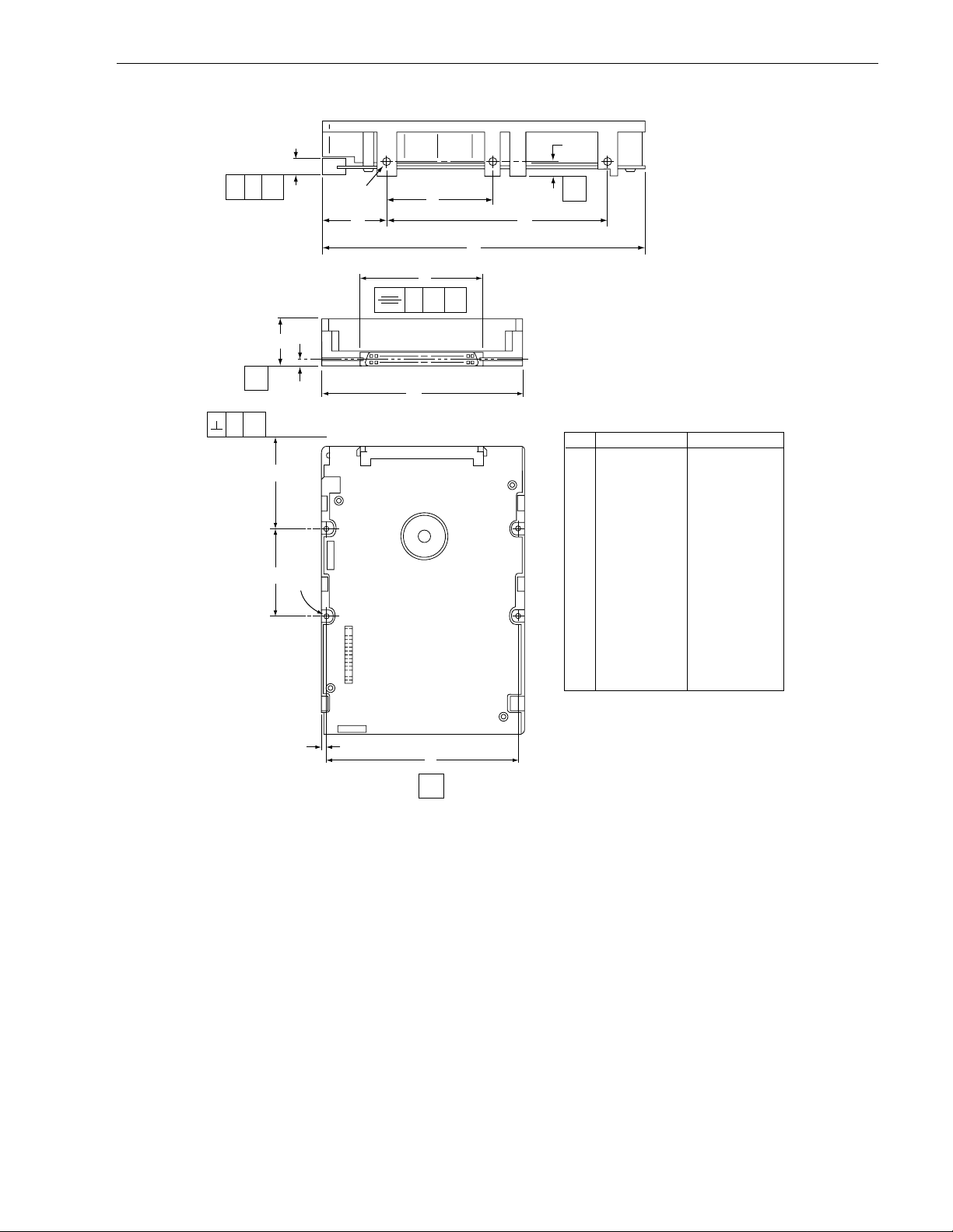
Cheetah 1 8LP Product Manual, Re v. F 33
K
S
-Z-
-Z-T//
A
M
[1]
L
H
B
R
-Z- -X-N
C
-Z-
J
Notes:
Mounting holes are 6-32 UNC 2B, three
[1]
on each side and four on the bottom.
Max screw penetration into side of drive
is 0.15 in. (3.81 mm). Max screw
tightening torque is 6.0 in-lb (3.32 nm)
with minimum full thread engagement of
0.12 in. (3.05 mm).
-X-
U
P
F
[1]
E
D
-X-
Figure 18. LC and LCV mounting conf igur ation dimensions
Dimension Table
Inches
A
1.028
5.787
4.000
3.750
.125
1.750
1.122
4.000
.250
1.638
.181
.040
1.625
2.618
.276
.015
.015
max
max
± .010
± .010
± .010
± .010
± .020
± .010
± .010
± .010
± .020
max
± .020
± .010
± .040
max
max
B
C
D
E
F
H
J
K
L
M
N
P
R
S
T
U
Millimeters
26.10
147.00
101.60
92.25
3.18
44.45
28.50
101.60
6.35
41.60
4.60
1.20
41.28
66.50
7.00
0.38
0.38
max
max
± .25
± .25
± .25
± .25
± .50
± .25
± .25
± .25
± .50
max
± .50
± .25
± 1.02
max
max

34 Cheetah 18LP Product Manual, Rev. F

Cheetah 1 8LP Product Manual, Re v. F 35
7.0 Defect and error management
The drive, as delivered, complies with this specification. The read error rate and specified storage capacity are
not dependent upon use of defect management routines by the host (initiator).
Defect and error management in the SCSI system involves the drive internal defect/error management a nd
SCSI systems error considerations (errors in communications between Initiator and the drive). Tools for use in
designing a defect/error management plan are bri efly outlined in this section, with references to other sections
where further details are given.
7.1 Dri ve internal defects
During the initial drive format operation at the factory, media defects are identified, tagged as b eing unusable,
and their locations recorded on the drive primar y defects list (referred to as the “P” list and also a s the ETF
defect list). At fac tory format time, these known defects are also reallocated, that is, reassigned to a new place
on the medium and the locati on listed in the defects reallocation table. The “P” list is not altered after factory
formatting. Locations of defects found and reallocated during error recovery procedures after drive shipment
are listed in the “G” list (defects growth list). The “P” and “G” lists may be referenced by the initiator using the
Read Defect Data command (see the appropriate SCSI Interface Product Manual).
7.2 Drive error recovery procedures
Whenever an error occurs during drive operation, the d rive, if programmed to do so, performs error recovery
procedures to attempt to recover the data. The error recovery procedures used depen d on the options previously set up in the error recovery parameters mode page. Error recovery and defect management m ay involve
the use of several SCSI commands, the details of which are descri bed in the S CSI Interface Product Manual.
The drive implements selectable error recovery time limits such as are required in video applications. For additional information on t his, refer to the Error Recover y Page table in the a ppropriate SCSI Interface Product
Manual, which describes the Mode Select/Mode Sense Error Recovery parameters.
The error recovery scheme supported by the drive provides a means to control the total error recovery time for
the entire command in addition to controlling the recovery level for a single LBA. The total amount of time spent
in error recovery for a command can be limited via the Recovery T ime Limit bytes in the Error Rec overy Mo de
Page. The total amount of time spent in error recovery for a single LBA can be limited via the Read Retry Count
or Write Retry Count bytes in the Error Recovery Mode Page.
The drive firmware error recovery algorithms consist of 11 levels for read recoveries and 5 levels for writes.
Table 5 equates the Read and Write Retr y Count with the maximum possible recovery time for read and write
recovery of individual LBAs. The times given do not include time taken to perform reallocations, if reallocations
are performed. Reallocations are performed when the ARRE bit (for reads) or AWRE bit (for writes) is one, the
RC bit is zero, and the Recovery Time Limit for the comm and has not yet been met . Time needed to perform
reallocation is not counted against the Recovery Time Limit.
The Read Continuous (RC) bit, when set to one, requests the disc dr ive to transfer the requested data length
without adding delays (for retries or ECC correction) that may be req uired to insure data integrity. The disc
drive may send erroneous data in order to maintain the continuous flow of data. The RC bit should only be
used when data integrity is not a concer n and speed is of utmost impor tance. If the Recovery Time Limit or
retry count is reached during error rec overy, the state of the RC b it is examined. If the RC bit is set, the dr ive
will transfer the unrecovered data with no error indication and continue to execute the remaining com mand. If
the RC bit is not set, t he drive will stop data transfer with the last goo d LBA, and report a “Check Condition,
Unrecovered Read Error.”

36 Cheetah 18LP Product Manual, Rev. F
Table 5: Read and write retry count maximum recovery times [1]
Read retry
count [1]
0 65.7 0 35.8
1 77.6 1 53.7
2 89.6 2 59.7
3 113.4 3 77.6
4 149.3 4 185.1
5 197. 0 5 (default) 226.9
6 244.8
7 334.3
8 394.0
9 441.8
10 549.2
11 2,009.2
12 (default ) 4,283.8
Maximum reco very ti me per
LBA (cumulative, msec)
Writ e re try
count
Maximum recovery time per
LBA (cumulative, msec)
[1] These values are subject to change.
Setting these retry counts to a value below the default setting could result in an increased unrecovered
error rate which may exceed the value given in this product manual. A setting of zero (0) will result in the
drive not performing error recovery.
For example, suppose the Read/Wr ite Recovery page has the RC bit set to 0, read retry count set to 4,
and the recovery time limit field (Mode Sense page 01, bytes 10 and 11) set to FF FF hex (maximum). A
four LBA Read command is allowed to take up to 209 msec recovery time for e ac h of the four LBAs in the
command. If the recovery time limit is set to 00 C8 hex (200 msec decimal) a four LBA read command is
allowed to take up to 200 msec for all error recovery within that command. The use of the Recovery Tim e
Limit field allows finer granularity on control of the time spent in error recov ery. The recovery time limit only
starts counting when the dr ive is executing error recovery and it restarts on each command. Therefore,
each command’s total recovery time is subject to th e recover y time limit. Note: A recover y time limit of 0
will use the drive’s def ault value of FF FF. Minimum recovery time limit is achieved by setting the Recovery
Time Limit field to 00 01.
7.3 SCSI system s errors
Information on the reporting of operational errors or faults across the interface is given in the appropriate SCSI
Interface Product Manual. Message Protocol System is described in the SCSI Interface Product Manual. Sev-
eral of the messages are used in the SCSI systems error management system. The Request Sense command
returns information to the host about numerous kinds of errors or faults. The Receive Diagnostic Results
reports the results of diagnostic operations performed by the drive.
Status returned by the drive to the Initiator is described in the appropriate SCSI Interface Product Manual. Status reporting plays a role in the SCSI system s error management and its use in that respect is described in
sections where the various commands are discussed.

Cheetah 1 8LP Product Manual, Re v. F 37
8.0 Installation
Note.
The first thing to do when installing a drive is to set the drive SCSI ID and set up certain operating options. This
is usually done by installing small shorting jum pers on t he pins of c onnectors J2 and J6 on t he PC BA (or J1Auxiliary on the LW/LWV models), or via the dr ive to host I/O signals on the L C model. Some us ers connect
cables to J6 or J5-Aux iliary and perfo rm the set- up us in g r e m o te switch es.
If your system is “SCAM” (SCSI Configured Automatically) compliant, the system assigns the drive SCSI ID
over the interface, so there is no need to be concerned about drive SCSI ID. Setting the drive SCSI ID jumpers
doesn’t hurt anything, but is not necessary.
If your syste m is not “SCAM” compliant you do need to set the drive SCSI ID using the ID jumpers.
Configure drive options
For option jumper locations and definitions refer to Figures 19, 20, and 2 1. Drive default mode parameters are
not normally needed for installation. Refer to Section 9.3.2 for default mode parameters if they are needed.
• Ensure that the SCSI ID of the drive is not the same as the host adapter. Most host adapters use SCSI ID 7
• If multiple devices are on the bus set the drive SCSI ID to one that is not presently used by other devices on
• If the drive is the only device on the bus, attach it to the end of the SCSI bus cabl e. The user, system integra-
These drives are designed to b e us ed only on single-ended (SE) or l ow voltage differential (LVD) busses. Do not install these drives on a high voltage differential (HVD) bus.
because ID 7 is the highest priority on both 8 and 16 bit data buses.
the bus.
tor, or host equipment manufacturer must provide external ter mi nators.
Note.
• Set all appropriate option jumpers for desired operation prior to power on. If jumpers are changed after
• Installation instructions are provided by host system documentation or with any additionally purchased drive
• Do not remove the manufacturer’s installed labels from the drive and do not cover with additional labels, as
Formatting
• It is not necessary to low level format this drive. The drive is shipped from the factory low level formatted in
• Reformat the drive if a different spare sector allocation scheme is selected.
• High level formatting the drive involv es assigning one or more partitions or logical drives to the drive volume.
8.1 Dri ve ID/optio n select heade r
Figures 19 and 20 show views of the drive ID select jumper connec tors. Figure 21 shows the option select
jumper connector for all models. Figure 19 shows the drive’s J 5-auxiliary jumper conn ector. Both J5-auxiliary
and J6 have pins for selecting drive ID and for connecting the remote LED cable. Only one or the other should
be used, although using both at the same time would not damage t he drive. The notes following the figures
describe the functions of the various jumper positions on the connectors J2, J5-Auxiliar y and J6. Suggested
part number for the jumpers used on J2 is Molex 52747-0211 (Seagate part number 77679052). A bag with the
two jumper plug types is shipped with the standard OEM drives.
For additional information about ter m inator requirement s, refer to Sections 9.8 and 9.9.
power has been applied, recycle the drive power to make the new settings effective.
installation software. If necessary see Section 10 for Seagate support services telephone numbers.
the manufacturer labels contain information required when servicing the product.
512 byte sectors.
Follow the instructions in the system manuals for the system into which the drive is to be installed.

38 Cheetah 18LP Product Manual, Rev. F
Drive
Front
Jumper Plug
(enlarged to
show detail)
Pin 1
[1]
J6
R
Reserved
L
E
E
A2A1A
A
S
D
0
3
SCSI ID = 0 (default)
SCSI ID = 1
SCSI ID = 2
SCSI ID = 3
SCSI ID = 4
SCSI ID = 5
SCSI ID = 6
SCSI ID = 7
[4]
SCSI ID = 8
SCSI ID = 9
SCSI ID = 10
SCSI ID = 11
SCSI ID = 12
SCSI ID = 13
SCSI ID = 14
SCSI ID = 15
Shipped with cover installed.
Host
[4]
Alternate
Usage Plug:
+5V
[6]
Reserved
Pins
1197531
6842
Ground
Do not install jumpers;
retain cover.
Dashed area is optional host circuitry (external to the drive)
[4]
connected to host supplied optional usage plug.
Do not connect anything to pins 13-20.
Figure 19. J6 jumper header
Drive Activity LED

Cheetah 1 8LP Product Manual, Re v. F 39
Drive HDA (rear view, PCB facing downward)
68 Pin
SCSI I/O Connector
J1
[4]
Pin 1
+5V Ground
Pin 1
[2]
SCSI ID = 0 (default)
SCSI ID = 1
SCSI ID = 2
SCSI ID = 3
SCSI ID = 4
SCSI ID = 5
SCSI ID = 6
SCSI ID = 7
SCSI ID = 8
SCSI ID = 9
SCSI ID = 10
SCSI ID = 11
SCSI ID = 12
SCSI ID = 13
SCSI ID = 14
SCSI ID = 15
J5
A3A2A
1197531
Host
Alternate
Usage Plug
Reserved
N.C.
[4]
12 10 8 6 4 2
+5V
+5V
Dashed area is optional host circuitry (external to the
drive) connected to host supplied optional usage plug.
N.C.
Ground
Drive Activity LED
A
1
0
A0A1A2A
[1] [2]
1P2P3P4P
J1-DC Power
For ID selection use
jumpers as shown or
connect a cable for
remote switching as
shown below.
Pins 1, 3, 5, and 7 are
optional connections to
switching circuits in host
equipment to establish
drive ID.
3
Remote Switches
Pins 2, 4, 6, and 8 are
normally not grounded.
They are driven low (ground)
for 250 ms after a Reset
or PWR ON to allow drive to
read SCSI ID selected.
PCB
Figure 20. J5 jumper header (on LW and LWV models only)

40 Cheetah 18LP Product Manual, Rev. F
*
Additional notes on these
functions in section 8.1.2.
Jumper
Positions
Force single-ended bus mode
Delay Motor Start
Enable Remote Motor Start
Write Protect
Parity Disable
Reserved
Term. Power to SCSI Bus
J2
SEDSMEWPP
D
Pin 1
R
R
E
EST
S
P
[3]
(applies to “LW” model only;
reserved on “LC” model)
J2
Jumper Plug
J6
J2
(enlarged to
show detail)
Drive
Front
Figure 21. J2 option select header
8.1.1 Notes for Figures 19, 20, and 21.
[1] Notes explaining the functions of the various jumpers on jumper header connectors J2, J5, and J6 are
given here and in Section 8.1.2. The term “
default
” means as standard OEM units are configured with a
jumper on those positions whe n shipped from factory. “Off” means no jumper is installed; “On” means a
jumper is installed. OFF or ON underlined is factory
default
condition.
The PCBA on LC and LCV models does not have connector J5. The J5 connector signals conform t o
SFF-8009 Revision 2.0, Unitized Connector for Cabled Drives, signal assignments for auxiliary connectors.
[2] These signals are also on 80-pin J1 I/O connector. See Tables 18 and 19.
[3] Vol tage supplied by the drive.

Cheetah 1 8LP Product Manual, Re v. F 41
8.1.2 Function description
J2
jumper
installation Jumper function descripti on
SE
On Forces drive to use single-ended I/O drivers/receivers only.
Off Drive can operate on the interface in low voltage differential mode or single-ended, depend-
ing on the voltage state of the I/O “DIFFSNS” line.
Default
is SE jumper not installed.
DS ME
Off
Off Spindle starts immediately after power up -
Default
setting.
Off On Drive spindle does not start until Start Unit command received from host.
On Off Spindle Startup is delayed by SCSI ID times 12 seconds after power is applied, i.e., drive 0
spindle starts immediately when DC power connected, drive 1 starts after 12 second delay,
drive 2 starts after 24 second delay, etc.
On On Drive spindle starts when Start Unit command received from host. Delayed start feature is
overridden and does not apply when ME jumper is installed.
WP
On Entire drive is write protected.
Off
Drive is not write protected.
Default
is WP jumper not installed.
PD
On Parity checking and parity error reporting by the drive is disabled.
Off
Drive checks for parity and reports result of parity checking to host.
Default
is PD jumper not installed.
RES
Off
Reserved jumper position.
Default
is no
RES
jumper installed.
TP1 (Do es not apply to “LC” or “LCV” models)
Off The drive does not supply terminator power to external terminators or to the SCSI bus I/O
cable.
On Drive supplies power to SCSI bus I/O cable. When drives have differential I/O circuits, a
jumper on the
TP1
position may be needed to power external terminators (see system docu-
mentation). These drives do not have terminator circuits on the drive.

42 Cheetah 18LP Product Manual, Rev. F
8.2 Dri ve orientation
The balanced rotary arm actuator design of the drive allows it to be mounted in any orientation. All drive performance characterization, however, has been done with the drive in horizontal (discs level) and vertical (drive on
its side) orientations, and these are the two preferred mounting orientations.
8.3 Cooling
Cabinet cooling must be designed by the customer so that the amb ient temp erature immediately s urrounding
the drive will not exceed temperat ure conditions specified in Section 6 .4.1, “Te mperature.” Specific consider-
ation should be given to make sure adequate air circulation is present around the printed circuit board (PCB) to
meet the requirements of Section 6.4.1, “Temperature.”
8.3.1 Air flow
The rack, cabinet, or drawer environment for the drive must provide heat removal from the electronics and
head and disc assembly (HDA). You should confirm that adequate heat removal is provided using the temperature measurement guidelines described in Section 6.4.1.
Forced air flow may be requi red to keep temperatures at or below the specified case temperatures of Table 3,
in which case the drive should be oriented, or air flow directed, so that the least amount of air flow resistance is
created while providing air flow to the electronics and HDA. Also, t he shortest possible path between the air
inlet and exit should be chosen to minimize the travel length of air heated by the drive and other heat sources
within the rack, cabinet, or drawer environment.
If forced air is determined to be neces sary, possible air-flow patterns are shown in Figure 22 . The ai r-flow patterns are created by one or more fans, either forcing or draw ing air as shown in the illustrations. Conduction,
convection, or other forced air-flow patterns are acceptable as long as the temperature measurement guidelines of Section 6.4.1 are met.
Above unit
Note. Air flows in the direction shown (back to front)
or in reverse direction (front to back)
Under unit
Note. Air flows in the direction shown or
in reverse direction (side to side)
Figure 22. Air flow (suggested)
Above unit
Under unit

Cheetah 1 8LP Product Manual, Re v. F 43
8.4 Dri ve moun ting
When mounting the drive using the bottom holes (x-y plane in Figure 16) care must be taken to ensure that the
drive is not physically distorted due to a stiff non-flat mounting surface. The allowable mounting surface stiffness is 80 lb/in (14.0 N/mm). The following equation and paragraph define the allowable mounting surface stiffness:
k * x = F < 15lb = 67N
where ‘k’ represents the mounting surface stiffness (units of lb/in or N/mm), and ‘x’ represents the out-of-plane
mountin g surface di stor tion (uni ts of inc hes or mi llimeters ). The o ut-of-plan e distor tion (‘x’) is determined by
defining a plane with t hree of the four mounting points fixed and evaluating the out-of-plane deflection of the
fourth mounting point when a known force (F) is applied to the fourth point.
Note.
Before mounting the drive in any kind of 3.5-inch to 5.25-inch adapter frame, verify with Seagate Technology that the drive can meet the shock and vibration specifications given herein while mounted in
such an adapter frame. Adapter frames that are available may not have a mechanical struct ure capable of mounting the drive so that i t can meet t he shoc k and vibration specifications listed in this manual.
8.5 Grounding
Signal ground (PCBA) and HDA ground are connected together in th e drive and cannot be separated by the
user. The equipment in which the drive is mounted is connected di rectly to the HDA and PCBA with no el ec tr ically isolating shock mounts. If it is desired for the system chassis to not be connected t o the HDA/PCBA
ground, the systems integrator or user must provide a nonconduc tive (electrically isolating) met hod of mount ing the drive in the host equipment.
Increased radiated emissions may result if you do no t provide the maximum s urface area ground connection
between system ground and drive ground. This is t he system designer’s and integrator’s responsibility.

44 Cheetah 18LP Product Manual, Rev. F

Cheetah 1 8LP Product Manual, Re v. F 45
9.0 Interface requirements
This section partially describes the interface requirements as implemented on the drives.
9.1 General description
This section describes in essentially general terms the interface requirements supported by the Cheetah 18LP.
No attempt is made t o describe all of t he minute details of c onditions and constraints that must b e c onsid ered
by designers when designing a system in whi ch this family of drives can properly operate. Seagate d eclares
that the drives operate in accordance with the appropriate ANSI Standards referenced in various places herein,
with exceptions as noted herein or in the appropriate Seagate SCSI Interfa ce Product M anual (P/N 77738479
for ST318203 and ST39103 drives and P/N 75789509 for ST318233 and ST39133 drives).
9.2 SCSI interface m essag es sup ported
Table 6 lists the messages supported by the SCSI-2 and SCSI-3 modes of the Cheetah 18LP family drives.
Table 6: SCSI messages supported by Cheetah 18LP family dri ves
Supported by
Message name Message code
Abort 06h Y
Abort-tag 0Dh Y
Bus device reset 0Ch Y
Clear ACA 16h N
Clear queue 0Eh Y
Command complete 00h Y
Continue I/O process 12h Y
Disconnect 04h Y
Extended messages 01h[1] Y
Identify 80h-FFh Y
Ignore wide residue (two bytes) 23h Y
Initiate recovery 0Fh N
Initiator detected error 05h Y
Linked command complete 0Ah Y
Linked command complete with flag 0Bh Y
Message parity error 09h Y
Message reject 07h Y
Modify data pointer [1] N
No operation 08h Y
Parallel Protocol Request (ST318233 and ST39133 only) [1] [2] Y
Queue tag messages (two bytes)
ACA 24h N
Head of queue tag 21h Y
Ordered queue tag 22h Y
Simple queue tag 20h Y
Release recovery 10h N
Restore pointers 03h Y
Save data pointer 02h Y
Synchronous data transfer req. [1] Y
Target transfer disable 13h Y
Terminate I/O process 11h Y
Wide data transfer request [1] Y
Notes.
[1] Extended messages (see the appropriate SCSI Interface Product Manual).
[2] Supports all options except qas_req and iu_req.
SCSI-2/3

46 Cheetah 18LP Product Manual, Rev. F
9.3 SCSI interface comm a nds suppor ted
Table 7 following lists the SCSI interface commands that are suppor ted in the SCSI -2, and SCSI-3 modes of
the drive. Cheetah 18LP Family drives can be changed back and forth bet ween SCSI-1 and SCSI-2/SCSI-3
modes using the Change Definition Command . OEM standard drives are shipped set to operate in SCSI-2/
SCSI-3 mod e.
Table 7: Commands suppor ted by Cheetah 18LP fami ly drive
Command name
Command
code
Supported by
SCSI-2/3
Change definition 40h Y (N for Ultra160)
Compare 39h N
Copy 18h N
Copy and verify 3A h N
Format unit [1] 04h Y
DPRY bit supported N
DCRT bit supported Y
STPF bit supported Y
IP bit supported Y
DSP bit supported Y
IMMED bit supported Y
VS (vendor specific) N
Inquiry 12h Y
Date code page (C1h) Y
Firmware numbers page (C0h) Y
Implemented operating def page (81h) Y
Jumper settings page (C2h) Y
Supported Vital product data page (00h) Y
Unit serial number page (80h) Y
Lock-unlock cache 36h N
Log select 4Ch Y
PCR bit Y
DU bit N
DS bit Y
TSD bit Y
ETC bit N
TMC bit N
LP bit N
Log sense 4Dh Y
Application client log page (0F) Y (Ultra160 only)
Cache statistics page (37h) Y
Non-medium error page (06h) Y
Pages supported list (00h) Y
Read error counter page (03h) Y
Self-test results page (10h) Y (Ultra160 only)
Start-stop cycle counter page (0Eh) Y (Ultra160 only)
Temperature page (0Dh) Y (Ultra160 only)
Veri fy error counter page (05h) Y
Write error counter page (02h) Y
Factory log page (3Eh) Y
Mode select (same pages as Mode Sense 1Ah) 15h Y [2]
Mode select (10) (same pages as Mode Sense 1Ah) 55h Y

Cheetah 1 8LP Product Manual, Re v. F 47
Table 7: Commands suppor ted by Cheetah 18LP fami ly drive (Continued)
Command name
Command
code
Supported by
SCSI-2/3
Mode sense 1Ah Y [2]
Caching parameters page (08h) Y
Control mode page (0Ah) Y
Disconnect/reconnect (02h) Y
Error recovery page (01h) Y
Format page (03h) Y
Information exceptions control page (1Ch) Y
Notch and Partition Page (0Ch) N
Power condition page (1Ah) Y
Rigid disc drive geometry page (04h) Y
Unit attention page (00h) Y
Verify error recovery page (07h) Y
Xor Control page (10h) N
Mode sense (10) (same pages as Mode Sense 1Ah) 5Ah Y
Prefetch 34h N
Read 08h Y
Read buffer (modes 0, 2, 3 supported). Ah and Bh modes
3Ch Y
also supported by Ultra160
Read c apacity 25h Y
Read defect data (10) 37h Y
Read defect data (12) B7h Y
Read extended 28h Y
DPO bit supported Y
FUA bit supported Y
Read long 3Eh Y
Reassign blocks 07h Y
Receive diagnostic results 1Ch Y
Supported diagnostics pages (00h) Y
Translate page (40h) Y
Release 17h Y
Release (10) 57h Y
Request sense 03h Y
Actual ret ry count bytes Y
Extended sense Y
Field pointer bytes Y
Reserve 16h Y
3rd party reser ve Y
Extent reservation N
Reserve (10) 56h Y
3rd pa rt r eserve Y
Extent reservation N
Rezero unit 01h Y
Search data equal 31h N
Search data high 30h N
Search data low 32h N
Seek 0B h Y
Seek extended 2Bh Y

48 Cheetah 18LP Product Manual, Rev. F
Table 7: Commands suppor ted by Cheetah 18LP fami ly drive (Continued)
Command
Command name
code
Send diagnostics 1Dh Y
Supported diagnostics pages (00h) Y
Translate page (40h) Y
Set limits 33h N
Start unit/stop unit (spindle ceases rotating) (1Ch) 1Bh Y
Synchronize cache 35h Y
Test unit ready 00h Y
Verify 2Fh Y
BYTCHK bit Y
Write 0Ah Y
Write and verify 2Eh Y
DPO bit Y
Write buffer (modes 0, 2, supported) 3Bh Y
Firmware download option (modes 5, 7 supported) .
Ah and Bh also supported by Ultra160. [3]
Write extended 2Ah Y
DPO bit Y
FUA bit Y
Write long 3Fh Y
Write same 41h Y
PBdata N
LBdata N
XDRead 52h N
XDWrite 50h N
XPWrite 51h N
Supported by
SCSI-2/3
Y
[1] The drive can format to any even number of bytes per sector from 512 to 4,096.
[2] Tables 9 show how individual bits are set and which are changeable by the host.
WARNING:
[3]
A power loss during flash programming can result in firm ware corr uption. Thi s usu ally makes
the drive inoperable.

Cheetah 1 8LP Product Manual, Re v. F 49
Table 8 lists the Standard Inquiry command data that the drive should return to the initiator per the format given
in the SCSI Interface Product Manual, Inquiry command sec tion.
Table 8: Cheetah 18LP family drive Standard Inquiry data
Bytes Data (HEX)
0-15 00 00 [02]1[12]28B 00 [01] [3E] 53 45 41 47 41 54 45 20 VENDOR ID
3
16-31 53 54 [33] [31] [38] [32] [30] [33] [ 4C] [57] [20]
32-47 R# R# R# R# S# S# S# S# S# S# S# S# 00 00 00 00
48-63 00 00 00 00 00 00 00 00 00 00 00 00 00 00 00 00
64-79 00 00 00 00 00 00 00 00 00 00 00 00 00 00 00 00
80-95 00 00 00 00 00 00 00 00 00 00 00 00 00 00 00 00
96-111 00 43 6F 70 79 72 69 67 68 74 20 28 63 29 20 [32] COPYRIGHT
5
112-127 [30] [30] [30]
128-143 72 69 67 68 74 73 20 72 65 73 65 72 76 65 64 20
1
01 means SCSI-1 implemented;
[]
20 53 65 61 67 61 74 65 20 41 6C 6C 20 NOTICE
20 20 20 20 20 PRODUCT ID
02 means SCSI-2/SCSI-3 implemented.
2
[]
The drive can be changed between these two configurations:
01 means response data in SC SI-1 form at and has co mpa tib ilit y with Com m on Co mm and S et data.
02 means response data in SCSI-2/SCSI-3 format (default is 02).
R# Four ASCII d igits represent ing the last four digits of the product Firmware Rele ase num ber. This informa-
tion is also given in th e Vital Product Dat a page C0h, t ogether with ser vo RAM and ROM rel ease numbers.
S# Eight ASCII digits representing the eight digits of the product serial number.
3
[]
Bytes 18 through 26 reflect model of drive. Shown here are hex values for Model ST318203LW.
For ST39103 drives, bytes 18 through 23 are: 33 39 31 30 33 00.
For ST318233 drives, bytes 18 through 23 are: 33 31 38 32 33 33.
For ST39133 drives, bytes 18 through 23 are: 33 39 31 33 33 00.
For “LW” models, bytes 24, 25 and 26 are 4C 57 20.
For “LWV” model s, bytes 24, 25 and 26 are 4C 57 56
For “LC” models, bytes 24, 25 and 26 are 4C 43 20.
For “LCV” models, bytes 24, 25 and 26 are 4C 43 56.
5
[]
Copyright Year - changes with actual year.
9.3.1 Inquiry Vi tal Product data
Instead of the standard Inquiry data shown in Table 8, the initiator can request several Vital Product Data
pages by setting the Inquiry command E VPD bit to one. The SCSI Interface Product Manual lists the Vita l
Product Data pages an d describes their formats. A separate Inquir y command must be se nt to the drive for
each Vital Product Data page the initiator wants the drive to send back.

50 Cheetah 18LP Product Manual, Rev. F
9.3.2 Mode Sense data
The Mode Sense com mand provides a me ans for the drive to repor t its operating parameters to the in itiator.
The drive maintains four sets of Mode paramete rs, Default values, Saved values, Current values and Changeable values.
Default values are hard coded in the drive firm ware that is stored in f lash EPROM no nvolatile memory on t he
drive PCBA. Default values can be changed only by downloading a complete set of new firmware into the flash
EPROM. An initiator can request and receive from the dr ive a list of default values and use those i n a Mode
Select command to set up new current and saved values, where the values are changeable.
Saved values are stored on the disk media using a Mode Select command. Only parameter values that are
allowed to be changed can be changed by this method. See “Changeable values” defined below. Parameters in
the saved values list that are not chan geable by the Mode Select command get t heir values from the default
values storage.
Current values are volatil e values currently being used by the drive t o control its operation. A Mode Select command can be used to c han ge t hese values (only thos e that are changeable). Originally, t hey are insta lled from
saved or default values after a power on reset, hard reset, or Bus Device Reset message.
Changeable values form a bit mask, stored in nonvolatile memory, t hat dictates which of the current values and
saved values can be changed by a Mode Select command. A “one” allows a change to a corresponding bit; a
“zero” allows no change. For example, in Table 9 refer to Mode page 01, in the row entitled “CHG”. These are
hex numbers representing the changeable values for mode page 01. Note that bytes 04, 05, 06, and 07 are not
changeable, because those fields are all zeros. If some changeable code had a hex value EF, tha t equates to
the binary pattern 1110 1111. If there is a zero in any bit position in the field, it means that bit is not changeable. Bits 7, 6, 5, 3, 2, 1, and 0 are changeable, because those bits are all ones. Bit 4 is not changeable.
Though the drive always reports non-zero values in bytes 00 and 0 1, those pa rticular bytes are never changeable.
The Changeable values list can only be changed by downloading new firmware into the flash EPROM.
On standard OEM dr ives the Saved values are taken from the default values list and stored into the saved val-
ues storage location on the media prior to shipping.
When a drive is powered up, it ta kes saved values from the media and stores them to the current values stor-
age in volatile memory. It is not possible to change the current values (or the saved values) with a Mode Select
command before the drive is up to speed and is “ready.” An attempt to do so results in a “Check Condition sta-
tus being returned.
Note.
Because there may be several different versions of drive control firmware in the total population of
drives in the field, the Mode Sense values given in the following tables may not exactly match those of
some drives.

Cheetah 1 8LP Product Manual, Re v. F 51
The following tables list the values of the data bytes returned by the drive in response to the Mode Sense command pages for SCSI-2/SCSI-3 implementation (see the appropriate SCSI Interface Product Manual).
Definitions: DEF = Default value. Standard drives are shipped configured this way.
CHG = Changeable bits; indicates if current and saved values are changeable.
Note.
Table 9: Mode sense data, ST318203 and ST318233 values (SCSI-2/3 implementation)
Bytes 0001020304050607080910 1112 1314151617181920212223
Mode
Sense
Data
Mode
Page
01 DEF
01 CHG 81 0A FF FF 00 00 00 00 FF 00 FF FF
02 DEF 82 0E 80 80 00 0A 00 00 00 00 00 00 00 00 00 00
02 CHG 82 0E FF FF 00 00 00 00 00 00 00 00 87 00 00 00
03 DEF 83 16 02 A5 00 00 00 04 00 00 01
03 CHG
04 DEF 84 16 00 26 2C 0C 00 00 00 00 00 00 00 00 00 00 00 00 00 00 27 20 00 00
04 CHG
07 DEF 87 0A 00 0B E8 00 00 00 00 00 FF FF
07 CHG 87 0A 0F FF 00 00 00 00 00 00 FF FF
Saved values for OEM drives are normally the same as the default values.
9F 00 10 08 02 1E B3 90 00 00 02 00
<------------------------------Mode P age Headers and Parameter Data Bytes---------------------------->
81 0A C0 0B E8 00 00 00 05 00 FF FF
[1]
2F 02 00 00 01 00 2C 00 38 40 00 00 00
83 16 00 00 00 00 00 00 00 00 00 00 00 00 00 00 00 00 00 00 00 00 00 00
84 16 00 00 00 00 00 00 00 00 00 00 00 00 00 00 00 00 00 00 00 00 00 00
08 DEF 88 12 14 00 FF FF 00 00 FF FF FF FF 80 03 00 00 00 00 00 00
08 CHG 88 12 B5 00 00 00 FF FF FF FF 00 00 A0
0A DEF 8A 0A 02 00 00 00 00 00 00 00 00 00
0A CHG 8A 0A 03 F1 00 00 00 00 00 00 00 00
1A DEF 9A 0A 00 03 00 00 00 01 00 00 00 04
1A CHG 9A 0A 00 03 00 00 00 00 00 00 00 00
1C DEF 9C 0A 00 00 00 00 00 00 00 00 00 01
1C CHG 9C 0A 8D 0F FF FF FF FF FF FF FF FF
00 DEF 80 02 00 00
00 CHG 80 02 77 40
Read capacity data
02 1E B3 8F 00 00 02 00
[2]
FF 00 00 00 00 00 00
[1] The value of this byte will change depending on the amount of buffer memory available.
[2] Though byte 12, bit 7 (A0) is shown as changeable, the FSW function govern ed by that bit is not imple-
mented by this drive.

52 Cheetah 18LP Product Manual, Rev. F
T able 10: Mode sense data, ST39103 and ST39133 values (SCSI-2/3 implementation)
Bytes 0001020304050607080910 1112 1314151617181920212223
Mode
Sense
9F 00 10 08 01 0F 59 C8 00 00 02 00
Data
Mode
<-------------------- -- -- ------M od e Page H e a ders and Parame te r Data Byt es - ------- -- -- ---------------->
Page
01 DEF
81 0A C0 0B E8 00 00 00 05 00 FF FF
01 CHG 81 0A FF FF 00 00 00 00 FF 00 FF FF
02 DEF 82 0E 80 80 00 0A 00 00 00 00 00 00 00 00 00 00
02 CHG 82 0E FF FF 00 00 00 00 00 00 00 00 87 00 00 00
03 DEF 83 16 0A EC 00 00 00 0D 00 00 01
03 CHG
83 16 00 00 00 00 00 00 00 00 00 00 00 00 00 00 00 00 00 00 00 00 00 00
[1]
30 02 00 00 01 00 2C 00 38 40 00 00 00
04 DEF 84 16 00 26 2C 06 00 00 00 00 00 00 00 00 00 00 00 00 00 00 27 20 00 00
04 CHG
84 16 00 00 00 00 00 00 00 00 00 00 00 00 00 00 00 00 00 00 00 00 00 00
07 DEF 87 0A 00 0B E8 00 00 00 00 00 FF FF
07 CHG 87 0A 0F FF 00 00 00 00 00 00 FF FF
08 DEF 88 12 14 00 FF FF 00 00 FF FF FF FF 80 03 00 00 00 00 00 00
08 CHG 88 12 B5 00 00 00 FF FF FF FF 00 00 A0
[2]
FF 00 00 00 00 00 00
0A DEF 8A 0A 02 00 00 00 00 00 00 00 00 00
0A CHG 8A 0A 03 F1 00 00 00 00 00 00 00 00
1A DEF 9A 0A 00 03 00 00 00 01 00 00 00 04
1A CHG 9A 0A 00 03 00 00 00 00 00 00 00 00
1C DEF 9C 0A 00 00 00 00 00 00 00 00 00 01
1C CHG 9C 0A 8D 0F FF FF FF FF FF FF FF FF
00 DEF 80 02 00 00
00 CHG 80 02 77 40
Read capacity data
01 0F 59 C7 00 00 02 00
[1] The value of this byte will change depending on the amount of buffer memory available.
[2] Though byte 12, bit 7 (A0) is shown as changeable, the FSW function govern ed by that bit is not imple-
mented by this drive.

Cheetah 1 8LP Product Manual, Re v. F 53
9.4 SCSI bus conditions and miscellaneous features supported
Asynchronous SCSI bus conditions suppor ted by the drive are listed below. These conditions cause the SCSI
device to perform certain ac tions and can alter the SCSI bus phas e sequence. Other miscellaneou s operating
features supported are also listed here. Refer to the appropriate SCSI Interface Product Manual, for details.
Table 11: SCSI bus conditions and other miscellaneous features
Condition/feature supported by:
SCSI-2/SCSI-3 Conditions or feature
N Adaptive Caching
Y Arbitrating System
Y Asynchronous Data Transfer
N Asynchron ous Event Notification
Y Attention Condition
N Auto Conti ngent Allegiance Condi ti on
Y Contingent Allegiance Condi tion
Y Deferred Error Handling
Y Disconnect/Reconnect
N High vo lt age differential (HVD) interface available
Y Low voltage differential (LVD) interface avai lable
Y Parameter Rounding (controlled by the Round bit in Mode Select page 0)
Y Queue tagging (up to 64 Queue tags supported)
Y Reporting actual retry count in Extended Sense bytes 15, 16 and 17.
Y Reset Condition
Y Segmented Caching
Y SMP = 1 in Mode Select command needed to sav e RPL and Rotat ional Offset by tes (See RPL in
the Rigid Drive Geometry P arameters table in the appropriate SCSI Interface Product Manual)
Y Synchronous Data Transfer
N Zero Latency Read
SCSI-2/SCSI-3 Status supported
YGood
Y Check Condition
Y Condition Met/Good
YBusy
Y Intermediate/Good
Y Intermediate/Condition Met/Good
Y Reservation Conflict
Y Queue Full
N ACA Active

54 Cheetah 18LP Product Manual, Rev. F
9.5 Synchronous data transfer
9.5.1 Synchronous data transfer periods supported ST318203 and ST39103 models:
Table 12 lists the synchronous data transfer periods supported by the drive. The data transfer period to be used
by the drive and the initiator is established by an exchange of message s during the Message Phase of operation. See the section on message protocol in the SCSI Interface Product Manual, part number 77738479.
Table 12: Synchronous data transfer peri ods
M (decimal)
Transfer period
(nanoseconds)
Transfer rate
(megatransfers/second)
9 12.5 80.0 [1]
10 25 40.0 [2]
12 50 20.0
25 100 10.0
50 200 5.0
[1] This transfer rate is only allowed when using the LVD interface.
[2] This transfer rate is only allowed when using the LVD interface on
ST318203 and ST39103 model drives.
ST318233 and ST39133 models:
The data transfer period to be used by the drive and the initiator is e stablished by an exchange of messages
during the Message P hase of operation. See the sec tion on message protocol in the SCSI Interface Product
Manual, par t numb er 757895 09. In the following tables, M is the synchronous period value (in the transfer rate
negotiation message) that represents the associated transfer period and transfer rate values.
Table 13 lists the synchronous data transfer periods supported by the d rive in DT Dat a phas e. DT Dat a p has e
is only allowed when using the LVD interface.
Table 13: Synchronous DT Data transfer per iods
M (decimal)
Transfer period
(nanoseconds)
Transfer rate
(megatransfers/second)
9 12.5 80.0
10 25 40.0
12 50 20.0
25 100 10.0
Table 14 lists the synchronous data transfer periods supported by the drive in ST Data phase. ST Data phase
is allowed with either L VD or SE interface except as noted.
Table 14: Synchronous ST Data transfer per iods
M (decimal)
Transfer period
(nanoseconds)
Transfer rate
(megatransfers/second)
10 25 40.0 [1]
12 50 20.0
25 100 10.0
50 200 5.0
[1] This transfer rate is only allowed when using the LVD interface.
9.5.2 REQ/ACK offset
The maximum value supported by the Cheetah 18LP family drives for REQ/ACK offset is 15 (0Fh).

Cheetah 1 8LP Product Manual, Re v. F 55
9.6 Physical interface
This section describes the connectors, cables, signals, terminators and bus timing of t he DC and SCSI I/O
interface. See Section 9.8 and Section 9.9 for additional terminator information.
Figures 23 and 24 show the locations of the DC power connector, SCSI interface connector, drive select headers, and option select headers.
Details of the physical, electrical and logical characteristics are g iven in sections following, while the SCSI
operational aspects of Seagate drive interfaces are given in the SCSI Interface Product Manual.
9.6.1 DC cable and connector
LW and LWV model drives recei ve DC power through a 4 pin connec tor (see Figure 25 for pin assignment)
mounted at the rear of the main PCBA. Recommended part numbers of the mating connector are listed below,
but equivalent parts may be used.
Typ e of cabl e Connector Contacts (20-1 4 AWG)
14 AWG MP 1-480424-0 A M P 60619-4 (Loose Piec e)
AMP 61117-4 (Strip)
LC and LCV model drives receive power through the 80-pin I/O connector. See Tables 18 and 19.

56 Cheetah 18LP Product Manual, Rev. F
J1
Pin 1
Pin 1A
J1
Pin 1
68 Pin
SCSI I/O
Connector
J5
Pin
1P
2P
3P
4P
Pin 1P
J5
Pin 1A
J1-DC Power
J2
Power
+12V
+12V ret
+ 5V ret
+ 5V
J1-DC Power
1P2P3P4P
PCB
J6
Figure 23. LW and LWV model drive physical interface (68-pi n J1 SCSI I/O connector)
80-pin
SCSI I/O
Connector
Pin 1
J2
J6
Figure 24. LC and LCV model drive ph ysical interface (80-pi n J1 SCSI I/O connector)

Cheetah 1 8LP Product Manual, Re v. F 57
9.6.2 SCSI interface physical description
The drive models described by this product manual support the physical interface requirements of the SCSI-3
Parallel Interface-2 (SPI-2) standards as defined in American National Standard docum ent X3T1 0/1 142D revision 14, and operate compat ibly at the interface with devices that suppor t earlier SCSI-2 and S CSI-3 standards. It should be noted that this is only true if the systems engineering has been correctly done, and if earlier
SCSI-2 and SCSI-3 devices respond in an acceptable manner (per applicable SCSI Standards) to reject newer
SCSI-3 protocol extensions that they don’t support.
The drives documented in this manual support single-ended and low voltage differential physical interconnects
(hereafter referred to as SE and LVD, respectively) as descr ibed in the ANSI SPI-2 standard. T hese drives
implement driver and receiver circuits that can operate either SE or LVD. However, they cannot switch dynamically between SE and LVD operation.
The drives typically operate on a daisy-chain interface in which other SCSI devices are also operating. Devices
on the daisy chain must all operate in the same mode, either SE or LVD, but not a mixture of these. On the
interface daisy chain, all signals are common between all devices on the chain, or bus, as it is also called. This
daisy chain of SCSI devices must be te rminated at both ends with the proper impe dance in order to operate
correctly. Do not terminate intermediate S CSI devices. In some cases, the SCSI devices at each end have
onboard termination circuits that can be enabled by installation of a jumper plug (TE) on the device. These termination circuits receive power from either a source internal to the device, or f rom a line in the interface cable
specifically powered for that purpose. LC, LCV, LW and LWV model drives do not have onboard termination circuits. Some type of external termination circuits must be provided for these drives by the end user or designers
of the equipment into which the drives will be integrated. See Standard X3T10/ 1142D, sections 6.4 and 6.5 for
the maximum number of devices that can successfully ope rate at various interface transfe r rates on SE and
LVD daisy chains.
LC and LCV model dr ives plug into PCBA or bulkhead connectors in the host. They may be connected in a
daisy-chain by the host backplane wiring or PCBA circuit runs that have adequate DC current carrying capacity
to suppor t the numbe r of dri ves plugged in to the PC BA o r bulkhead c onne ctors. A s ingle 80-pi n I /O c onnect or
cable cannot suppor t the DC current needs of several drives, so no daisy chain cables beyond the bulkhead
connectors should be used. A single drive connec ted via a cable to a host 80-pin I/O conne ctor is not recommended.
Table 15 shows the interface transfer rates supported by the various drive models defined in this manual.
Table 15: Interface transfer rates supported
Maximum transfer rate
Interface typ e /
drive models
SE
ST318203
ST318203
ST39103
ST39103
LVD
ST318203
ST318203
LC/LCV
LW/LWV
LC/LCV
LW/LWV
LC/LCV
LW/LWV
Asynchronous Fast-5 Fast-10
yes yes yes yes no no
yes yes yes yes yes no
Fast-20
(Ultra)
Fast-40
(Ultra2)
Fast-80
(Ultra160)
ST39103LC/LCV
ST39103LW/LWV
SE
LVD
ST318233
ST318233
ST39133
ST39133
ST318233
ST318233
LCV
LWV
LCV
LWV
LCV
LWV
yes yes yes yes no no
yes yes yes yes yes yes
ST39133LCV
ST39133LWV

58 Cheetah 18LP Product Manual, Rev. F
9.6.3 SCSI interface cable requirements
The characteristics of cables used to connect SCSI -3 parallel interface devices are discussed in detail in section 6 of ANSI Standard X3T10/11 42D. The cable characteristics that must be considered when interconne cting the drives described in this manual in a SCSI-3 parallel, daisy-chain interconnected system are:
• characteristic impedance (see Section 6.1)
• propagation delay (see Section 6.1)
• cumulative length (see Sections 6.4 and 6.5)
• stub length (see Sections 6.4 and 6.5)
• device spacing (see Sections 6.4 and 6.5)
To minimize discontinuances and signal reflections, cables of different impedances should not be used in the
same bus. Implementations may require trade-offs in s hielding effectiveness, cable length, number of loads
and spacing, transfer rates, and cost to achieve satisfactory system operation. If shielded and unshielded
cables are mixed within the same SCSI bus, the effect of impedance m ismatch mus t be carefully considered.
Proper impedance matching is especially important in order to maintain adequate margin at FAST-20 and
FA ST-40 S CSI transfer rates.
Note.
For LVD operation, twisted pair cables are recommended. For LVD Fast-40 operation, twisted pair
cables are strongly recommended. For Fast-80 (Ultra160) operation, twisted pair cables are required.
LC and LC V m odels:
The 80-pin connector option is intended for use on drives that plug directly into backplane connector in the host
equipment. In such installations, all backplane wiring segments are subject to the electromagnetic concepts
presented in Standard X3T10/1142D, section 6. For LC and LCV model drives, installations with connectors on
cables are not recommended.
9.6.4 Mating connectors
Part numbers for the different type connectors that mate with the various Cheetah 18LP I/O connectors are
given in the sections following.
9.6.4.1 Mating connectors for LW and LWV m odel drives
The nonshielded cable connector shall be a 68 conductor connector consisting of two rows of 34 male contacts
with adjacent contacts 0.050 inch (1.27 mm) apart.
Recommended mating flat cable connector part numbers are:
Amp Model 786096-7 Female, 68-pin, panel mount
Amp Model 786090-7 Female, 68-pin, cable mount
Amp Model 749925-5 (50 mil conductor centers, 28 or 30 AWG wire)
Use two, 34 conductor, 50 mil center flat cable with this connector.
This type connector can only be used on cable ends. [1]
Amp Model 88-5870-294-5 W/O Strain Relief (25 mil conductor centers, 30 AW G wire).
Use either on cable ends or in cable middle section for daisy-chain
installat ions [1].
Amp Model 1-480420-0 Power connector 4 circuit housing
Berg 69307-012 12-position, 2 x 6, 2 mm receptacle housing
[1] See Figure 25.
The drive device connector is a nonshielded 68 conductor connector consist ing of two rows of 34 female pins
with adjacent pins 50 mils apart. The connector is keyed by means of its shape (see Figure 26).

Cheetah 1 8LP Product Manual, Re v. F 59
9.6.4.2 Mating connectors for LC and LCV model drives
The nonshielded connector shall be an 80-conductor connector consisting of two rows of 40 contacts with adjacent contacts 50 (1.27 mm) mils apart (see Figure 27). I/O conne ction using a cable is not recommended. The
length and size of the host equipment DC power carrying conduc tors from the DC power source to the host
equipment 80-pin disk drive interface connector(s) should be strictly designed according to proper power transmission design concepts. No possibi lity for the equipment user to attach an 80-pin cable/connect or should be
allowed, since the length of the DC power carrying conductors could not be controlled and therefore could
become too long for safe p ower transmission to the drive. Daisy-chain 80-conductor cables should especially
not be allowed, since the power-carrying conductors on the 80-conductor interface were not intended to support a series of drives.
To insure that both drive connector and host equipment mating connector mate proper ly, both drive c onnector
and host equipment mating connect or must meet th e provisions of “SFF-8 046 S pec ification for 80-pin connector for SCSI Disk Drives.”

60 Cheetah 18LP Product Manual, Rev. F
Recommended mating 80-position PCBA mount con nectors:
Straight-in connect or Hot plug version (with ground guide-pin)
Seagate P/N: 77678703
Amp US P/N:
or
Amp US P/N:
or
2-557103-1
94-0680-02-1
2-557103-2
94-0680-02-2
787311-1 with polarization
787311-2 without polarization
Amp Japan P/N: 5-175475-9
Righ t -angle to PCB A conne ctors
Seagate P/N: 77678559 Amp US P/N: 2-557101-1 Amp Japan P/N: 5-175474-9
For additional information call Amp FAX service at 1-800-522-6752.
“LW” Model
Drive
Terminator
[6]
SCSI ID 1
[2]
SCSI ID 0
[2]
[7]
2 through X
SCSI devices [4]
Pin 1
(check your
adapter for Pin 1 location)
SCSI ID 7 [5]
[1]
Host Adapter
PCB
[3]
[1] Closed end type 68-pin connector used. Ter m inat ors enabled.
[2] Open end type (in-line application) connector used.
[3] Host need not be on the end of the daisy-chain. Another device can be on the end with the terminator, the
host having no terminator.
[4] Total interface cable length must n ot exceed that specified in ANSI doc ument X3T10/1142D (including
host adapter/initiator). The cable length restriction limits the total number of devices allowed.
[5] SCSI ID7 has highest arbitration priority, then ID15 to ID8 (ID 8 very lowest).
[6] Last drive on the daisy chain.
[7] Open-end type 68-pin connector used. If end device, use external terminator and closed-end type 68-pin
connector.
Figure 25. SCSI daisy chain interface cabl ing for LW and LWV drives

Cheetah 1 8LP Product Manual, Re v. F 61
3.650±.005
.100
(2.54)
.155
.050
.022
.346
1.650 .3937 .600
.519
(13.18)
1.816
(46.13)
Position 1
.315
(8.00)
.270
.0787 .200
.020 .047
.60
(15.24)
Pos.
1
Pos.
1
3
4
12
.20
(5.08)
.085
(2.16)
typ
x 45° chamfer
typ
.315 ± .010
(8.00)
.218
(5.54)
Pos. 68
.050
(1.27)
1.650
(41.91)
.980
(24.89)
1.368
(37.74)
Pos. 35
.0787
(2.00)
Pos.
2
.840 ± .005
(21.34)
.767
(19.48)
3.650
(92.71)
Figure 26. Nonshielded 68 pin SCSI device connector used on LW and L W V drives
+.001
–.002
dia
.083
(2.1)
Trifurcated Pins
(4 places)

62 Cheetah 18LP Product Manual, Rev. F
7.00
(.276)
Pin 1
0.15
62.15
(2.447)
0.15
Housing
MYM
–Y–
± 0.15
(± .005)
MYM
57.87
(2.278)
Grounding
0
–0.15
+ .000
[
– .006
Pins
[
C
of Datum Y
L
12.70
(.500)
2.15±0.10
2 places
X
End View
Front View
Insert mating
I/O connector
Top View
Contact
0.50
(.020)
0.3
(.012)
1.27
(.05)
Typ
MYM
Pin 1 Pin 40
Pin 41 Pin 80
C
L
X
of Datum Y
Figure 27. Nonshielded 80 pin SCSI “SCA-2” connector, used on LC and LCV drives
Grounding
Pins
Back View

Cheetah 1 8LP Product Manual, Re v. F 63
T able 16: L W 68-conductor single-ended (SE) P cable signal/pin assignm ents [11]
Note.
A minus sign preceding a signal name indicates that signal is active low.
Signal
name [1]
Connector
contact
number [3]
Cable conductor
number [2]
Connector
contact
number [3]
Signal
name [1]
GND 1 1 2 35 –DB12
GND 2 3 4 36 –DB13
GND 3 5 6 37 –DB14
GND 4 7 8 38 –DB15
GND 5 9 10 39 –DBP1
GND 6 11 12 40 –DB0
GND 7 13 14 41 –DB1
GND 8 15 16 42 –DB2
GND 9 17 18 43 –DB3
GND 10 19 20 44 –DB4
GND 11 21 22 45 –DB5
GND 12 23 24 46 –DB6
GND 13 25 26 47 –DB7
GND 14 27 28 48 –DBP
GND 15 29 30 49 GND
GND 16 31 32 50 GND
TermPwr 17 33 34 51 TermPwr
TermPwr 18 35 36 52 TermPwr
Reserved 19 37 38 53 Reserved
GND 20 39 40 54 GND
GND 21 41 42 55 –ATN
GND 22 43 44 56 GND
GND 23 45 46 57 –BSY
GND 24 47 48 58 –ACK
GND 25 49 50 59 –RST
GND 26 51 52 60 –MSG
GND 27 53 54 61 –SEL
GND 28 55 56 62 –C/D
GND 29 57 58 63 –REQ
GND 30 59 60 64 –I/O
GND 31 61 62 65 –DB8
GND 32 63 64 66 –DB9
GND 33 65 66 67 –DB10
GND 34 67 68 68 –DB11
Notes [ ]:
See page following Table 19.

64 Cheetah 18LP Product Manual, Rev. F
T able 17: L W 68-conductor LVD P cable signal/pin assignments [ 11]
Note.
Signal
name [1]
A minus sign preceding a signal name indicates that signal is active low.
Connector
contact
number [3]
Cable conductor
number [2]
Connector
contact
number [3]
Signal
name [1]
+DB12 1 1 2 35 –DB12
+DB13 2 3 4 36 –DB13
+DB14 3 5 6 37 –DB14
+DB15 4 7 8 38 –DB15
+DBP1 5 9 10 39 –DBP1
+DB0 6 11 12 40 –DB0
+DB1 7 13 14 41 –DB1
+DB2 8 15 16 42 –DB2
+DB3 9 17 18 43 –DB3
+DB4 10 19 20 44 –DB4
+DB5 11 21 22 45 –DB5
+DB6 12 23 24 46 –DB6
+DB7 13 25 26 47 –DB7
+DBP 14 27 28 48 –DBP
Ground 15 29 30 49 Ground
DIFFSNS [8] 16 31 32 50 Ground
TermPwr 17 33 34 51 TermPwr
TermPwr 18 35 36 52 TermPwr
Reserved 19 37 38 53 Reserved
Ground 20 39 40 54 Ground
+ATN 21 41 42 55 –ATN
Ground 22 43 44 56 Ground
+BSY 23 45 46 57 –BSY
+ACK 24 47 48 58 –ACK
+RST 25 49 50 59 –RST
+MSG 26 51 52 60 –MSG
+SEL 27 53 54 61 –SEL
+C/D 28 55 56 62 –C/D
+REQ 29 57 58 63 –REQ
+I/O 30 59 60 64 –I/O
+DB8 31 61 62 65 –DB8
+DB9 32 63 64 66 –DB9
+DB10 33 65 66 67 –DB10
+DB11 34 67 68 68 –DB11
Notes [ ]:
See page following Table 19.

Cheetah 1 8LP Product Manual, Re v. F 65
Table 18: LC 80-pin single-ended ( SE) I/O connector pin assignments [11]
Note.
A minus sign preceding a signal name indicates that signal is active low.
Connector
Signal
name [1]
contact
number [3]
Signal
number [3]
Contact
name[1]
12 V CHARGE 1 41 12 V GND
12 V 2 42 12 V GND
12 V 3 43 12 V GND
12 V 4 44 MATED 1
NC [10] 5 45 NC [10]
NC [10] 6 46 DIFFSNS [8]
–DB11 7 47 GND
–DB10 8 48 GND
–DB9 9 49 GND
–DB81050GND
–I/O1151GND
–REQ1252GND
–C/D1353GND
–SEL1454GND
–MSG1555GND
–RST1656GND
–ACK1757GND
–BSY1858GND
–ATN1959GND
–DBP2060GND
–DB72161GND
–DB62262GND
–DB52363GND
–DB42464GND
–DB32565GND
–DB22666GND
–DB12767GND
–DB02868GND
–DP12969GND
–DB15 30 70 GND
–DB14 31 71 GND
–DB13 32 72 GND
–DB12 33 73 GND
+5 V3474MATED 2
+5 V35755 V GND
+5 V36765 V GND
NC [10] 37 77 ACTIVE LED OUT [4] [9]
RMT- STA RT [5] [9] 38 78 D LYD-START [6] [9]
SCSI ID (0) [7] [9] 39 79 SCSI ID (1) [7] [9 ]
SCSI ID (2) [7] [9] 40 80 SCSI ID (3) [7] [9 ]
Notes [ ]:
See page following Table 19.

66 Cheetah 18LP Product Manual, Rev. F
T able 19: LC 80-pin single-ended (LVD) I/O connector pin assignments [11]
Note.
Signal
name [1]
A minus sign preceding a signal name indicates that signal is active low.
Connector
contact
number [3]
Signal
number [3]
Contact
name[1]
12 V CHARGE 1 41 12 V GND
12 V 2 42 12 V GND
12 V 3 43 12 V GND
12 V 4 44 MATED 1
NC [10] 5 45 NC [10]
NC [10] 6 46 DIFFSNS [8]
–DB11 7 47 +DB11
–DB10 8 48 +DB10
–DB9 9 49 +DB9
–DB81050+DB8
–I/O1151+I/O
–REQ1252+REQ
–C/D1353+C/D
–SEL1454+SEL
–MSG1555+MSG
–RST1656+RST
–ACK1757+ACK
–BSY1858+BSY
–ATN1959+ATN
–DBP2060+DBP0
–DB72161+DB7
–DB62262+DB6
–DB52363+DB5
–DB42464+DB4
–DB32565+DB3
–DB22666+DB2
–DB12767+DB1
–DB02868+DB0
–DBP1 29 69 +DP1
–DB15 30 70 +DB15
–DB14 31 71 +DB14
–DB13 32 72 +DB13
–DB12 33 73 +DB12
+5 V3474MATED 2
+5 V35755 V GND
+5 V CHARGE 36 76 5 V GND
NC [10] 37 77 ACTIVE LED OUT [4] [9]
RMT_ STA RT [ 5 ] [9] 3 8 78 D LYD_STA RT [6] [9]
SCSI ID (0) [7] [9] 39 79 SCSI ID (1) [7] [9 ]
SCSI ID (2) [7] [9] 40 80 SCSI ID (3) [7] [9 ]
Notes [ ]
: See page following this table.

Cheetah 1 8LP Product Manual, Re v. F 67
Notes [ ] for Tables 16 through 19.
[1] See Section 9.6.4.1 for detailed electrical characteristics of these signals.
[2] The conductor number refers to the conductor position w hen using 0. 025-inch (0.635 mm) centerline flat
ribbon cable. Other cables types may be used to implement equivalent contact assignments.
[3] Connector contacts are on 0.050 inch (1.27 mm) centers.
[4] Front panel LED signal; indicates drive activity for host front panel hard drive activity indicator.
[5] Asserted by host to enable Motor Start option (enables starting m otor via SCSI bus command).
[6] Asserted by host to enable Delay ed Motor Start option (motor starts at power on or after a delay of 12 sec-
onds times drive ID). This and [3] above are mutually exclusive options.
[7] Binary code on A3, A2, A1 and A0 asser t ed by host to set up SCSI bus ID in drive.
[8] GND provides a means for differential devices to detect the presence of a single ended device on the bus.
Drive will not operate I/O bus at Ultra2 SCSI data rates if this is grounded.
[9] Signals [4] through [7] are used in place of installing jumpers and cables on option select connectors J2
and J6. See Section 8.1.1 notes.
[10] “NC” means no connection.
[11] 8 bit devices which are connected to the 16 data bit LVD I/O shall leave the following signals open: –DB8,
–DB9, –DB10, –DB11, –DB12, –DB13, –DB14, –DB15, and –DBP1.
8 bit devices which are connected to the 16 data bit single-ended (SE) I/O shall have the followi ng signals
open: DB8, –DB9, –DB10, –DB11, –DB12, –DB13, –DB14, –DB15, and –DBP1.
All other signals should be connected as shown.
9.7 Electrical descr iption
Cheetah 18LP LW, LWV, LC and LCV model drives are mu ltimod e devices. That is, the ir I/O c ircuits c an operate as either single-ended or low voltage differential drivers/receivers (selectable using the I/O “DIFFSENS”
line).
See ANSI Standard X3T10/1142D for ST318203 and ST39103 model electrical spec ifications.
See ANSI SPI-3 specification T10/1302D for ST318233 and ST39133 model electrical specifications.
9.7.1 Multimode—SE and LVD alternatives
When the interface “DIFFSNS” line is between +0.35 V a nd +0 .5 V, the drive interface circuits operate singleended and up to an d including 20 M transfers/s (Fast-20 or Ultra SCSI). When “DIFFSNS” is be tween +0. 7 V
and +1.9 V, the ST3182 03 and S T39103 d rive interface circuits operate low voltage differential and up to a nd
including 40 M transfers/s or less (Fast-40 or Ultra2 SCSI); the ST318233 and ST39 133 dri ve interface circuits
operate low voltage differential and up to and including 80 M transfers/s or less (Fas t-80 or Ultra160 SCSI).
This multimode design does not allow dynamically changing transmission modes. Drives must operate only in
the mode for which the installation and interface cabling is designed. Multimode I/O circuits use d by these
drives do not operate at high voltage differential levels and should never be exposed to high voltage differential
environments unless the common mode voltages in the environment are controlled to safe leve ls for singleended and low voltage differential devices (see the ANSI SPI-2 specification X3T10/1142 D for ST318203 and
ST39103 models; see the ANSI SPI-3 specification T10/1302D for ST318233 and ST39133 models).
Multimode signals
Multimode circuit SE alternative signal characteristics are the same as descr ibed elsewhere in Section 9.7.1.
The SE alternative for these circuits is selected as described above. SE cables and termination must be used.
LC, LCV, LW and LWV model drives do not have onboard terminators. The Multimode signal lines (either SE or
LVD) should be terminated with 110 ohm active terminator circuits at each end of the total cable. Termination of
the I/O lines must be provided for by the Host equipment designers or end users.
The SE and differential alternatives are mutually exclusive.
Output characteristics
Each signal (V
) driven by LVD in terface drivers shall have the following output characteristics when measured
s
at the disc drive connector:

68 Cheetah 18LP Product Manual, Rev. F
Steady state Low level output voltage* = –.95 V = < Vs = < –1.55 V (signal negation/logic 0)
Steady state High level output voltage* = –.95 V = < V
Differential voltage = +
0.6 V minimum with common-mode voltage ranges 0.700 V = < Vcm = < 1.800 V.
= < 1.55 V (signal assertion/logic 1)
s
*These voltages shall be measured between the output terminal and the SCSI device’s logic ground reference.
The output characteristics shall additionally conform to EIA RS-485.
LVD Differential
Driver
Signal +
Signal –
LVD Differential
Driver
Signal +
Signal –
| = .6V
|V
0
Figure 28. LVD output signals
1.55V
.95V +15ma
.95V
1.55V –15ma
–15ma
+15ma
= True / Logic 1 / Assertion
V
0
= False / Logic 0 / Negation
V
0
Input characteristics
Each signal (Vs) received by LVD interface receiver circuits shall have the following input characteristics when
measured at the disk drive connector:
Steady state Low level output voltage* = 0.030 V = < V
Steady state High level output voltage* = –3.6 V = < V
Differential voltage = +
0.30 V minimum with common-mode voltage ranges 0.700 V = < Vcm = < 1.800 V.
= < 3.6 V (signal negation/logic 0)
s
= < –0.030 V (signal assert ion/log ic 1)
s
(X3T10/1142D revision 13, p. 152)
*These voltages shall be measured between the output terminal and the SCSI device’s logic ground reference.
Input characteristics shall additionally conform to EIA RS-485-983.
VCCA VCCB
LVD Signal Drivers
LVD
Receiver
LVD Signal Drivers
Single
Ended
Receiver
Single
Ended
Negation
Driver
Single
Ended
Assertion
Driver
Single
Ended
Ground
Driver
Single
Ended
Circuitry
Ground
Single Ended:
LVD:
GND
+Signal
Figure 29. Typical SE-LVD alternative transmitte r receiver circuits
–Signal
–Signal
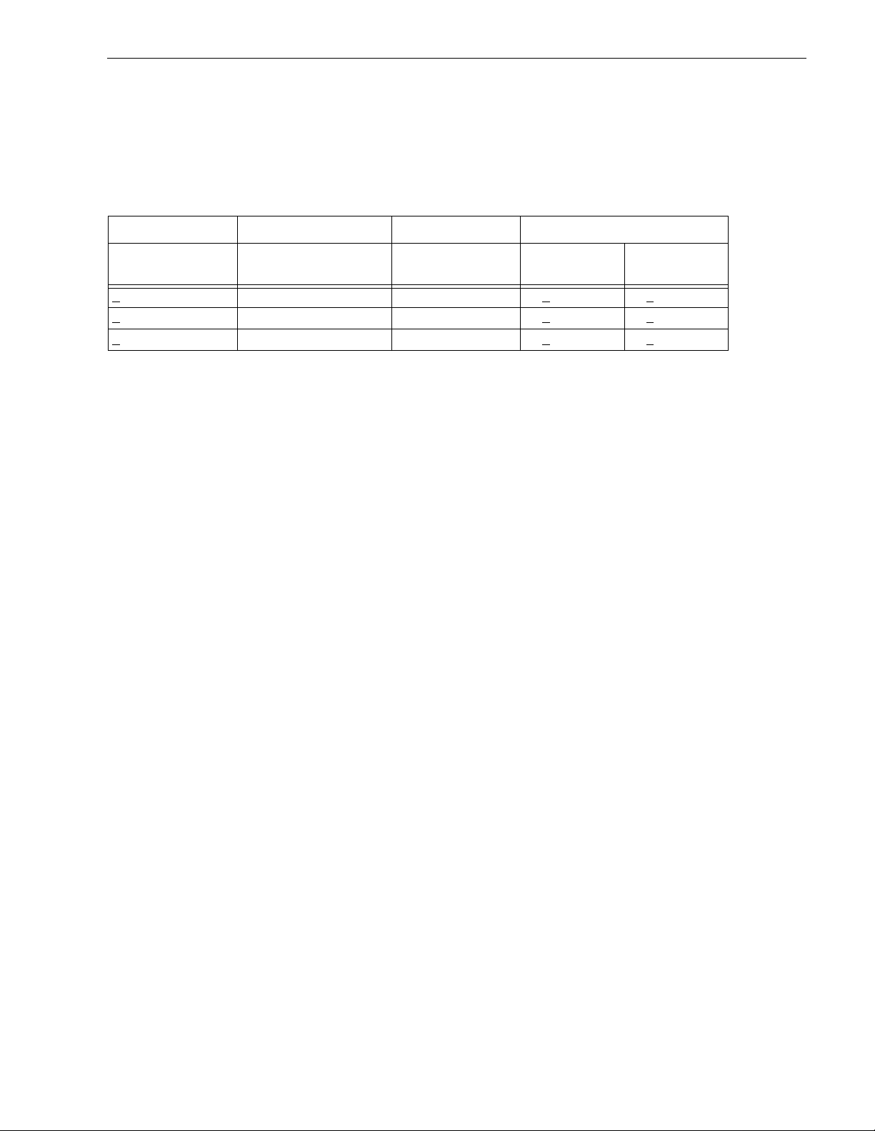
Cheetah 1 8LP Product Manual, Re v. F 69
9.7.1.1 Single-ended drivers/receivers
The maximum total cable length allowed with drives using single-ended I/O driver and receiver circuits
depends on several factors. Table 20 l ists the maximum lengths allowed for different configurations of drive
usage. These values are from the SPI-2 document. All device I/O lines must have equal to or less than 25 pf
capacitance to ground, measured at the beginning of the stub.
Table 20: Cable characteristics for single-ended circuits
Transmission line impedance
I/O transfer rate
10M transfers/s 16 (wide SCSI bus) 6 meters (19.7 ft) 90 + 6 Ohms 90 + 10 Ohms
<
20M tran sfer s /s 4 (wide SCSI bus ) 3 meters (9 .8 ft) 90 + 6 Ohms 90 + 10 Ohms
<
20M transfers/s 8 (wide SCSI bus) 1.5 meter s (4.9 ft) 90 + 6 Ohms 90 + 10 Ohms
<
Maximum number of
devices on the bus
maximum cable
length allowed
REQ/ACK Other signals
A stub length of no more than 0.1 meter (0.33 ft) is allowed off the mainline interconnection with any connected
equipment. The stub length is measured from the transceiver to the connection to the mainline SCSI bus.
Single-ended I/O cable pin assignments for LW and LWV drives are shown in Table 17.
Single-ended I/O pin assig nments for LC and LCV models are shown in Ta ble 18. The LC model does not
require an I/O cable. It is designed to connect directly to a back panel connector.
9.7.1.2 Low voltage differential I/O circuits
The maximum total cable length for use with drives using LV D I/O drivers and receiver circuits is 12 meters
(39.37 ft.). A stub length of no more than 0.1 meter is allowed off the mainline interconnection with any connected equipment. LVD I/O pin assignments for LW and LWV model drives are shown in tables 16 and 17. LVD
I/O pin assignments for LC and LCV model drives are shown in tables 18 and 19.
9.7.1.3 General cable characteristics
A characteristic impedance of 100 ohm + 10% is recommended for unshielded flat or twisted pair ribbon cable.
However, most available cables have a somewhat lowe r characteristic impedan ce. To Minimize discont inuities
and signal reflections, cables of different impedances should not be us ed in the same bus. Implementations
may require tradeoffs in shielding effectiveness, cable length, the numbe r of l oads, transfer rates, and cost to
achieve satisfactory system operation. If shielded and unshielded cables are mixed within the same SCSI bus,
the effect of impedance mismatch must be carefully considered. Proper impedance matching is especially
important in order to maintain adequate margin at fast SCSI transfer rates.
9.8 Terminator requirements Caution:
These drives do not have onboard internal terminators. The user, systems integrator or host equipment manufacturer must provide a terminator arrangement external to the drive when termination is
required. For LW and LWV drives, terminator modules can be purchased that plug between the
SCSI I/O cable and the d rive I/O connector or on the en d of a shor t I/O cable st ub extending past
the last cable connector. LC and LCV drives are designed to be plugged into a backpanel connector without cabling.
9.9 Terminator power LW and LW V drives
You can configure terminator power from the drive to the SCSI bus or have the host adaptor or other device
supply terminator power to the external ter minator. See Sect ion 8.1 for illustrations that show how to place
jumpers for this configuration.
LC and LCV drives
These drives cannot furnish terminator power because no conducto rs in the 80-pin I/O connector are devoted
to terminator power.

70 Cheetah 18LP Product Manual, Rev. F
9.10 Disc drive SCSI timing
T able 21: Disc drive SCSI timing
These values are not current Cheetah 18LP values, but are listed for information only .
Description
Waveform
symbol [1]
Waveform
table [1] Typical timing
Target Select Time (no Arbitration) T00 N/A <1 µs
Target Select Time (with Arbitration) T01 4.5-1,2 1.93 µs
Target Select to Command T02 4.5-1 3.77 µs
Target Select to MSG Out T03 4.5-2 1.57 µs
Iden tify MSG to Com mand T04 4. 5 - 3 3.36 µs
Command to Status T05 4.5-5 Command Dependent
Command to Data (para. In) T06 4.5-9 Command Dependent
Command to Data (para. Out) T07 4.5-10 Command Dependent
Command to Data (Write to Data Buffer) T08 4.5-10 Command Dependent
Command to Disconnect MSG T09 4.5-6 Command Dependent
Disconnect MSG to Bus Free T10 4.5-6,14 0.52 µs
Disconnect to Arbitration (for Reselect)
T11 4.5-6 Command Dependent
This measures disconnected CMD overhead
Target win Arbitration (for Reselect) T12 4.5-7 3.00 µs
Arbitration to Reselect T 13 4.5-7 1.60 µs
Reselect to Identify MSG In T14 4.5-7 1.39 µs
Reselect Identify MSG to Status T15 4.5-8 Command Dependent
Reselect Identify MSG to Data (media) T16 4.5-11 Command Dependent
Data to Status T17 4.5-15 Command Dependent
Status to Command Complete MSG T18 4.5-5,8,15 0.98 µs
Command Complete MSG to Bus Free T19 4.5-5,8,15 0.51 µs
Data to Save Data Pointe r MSG T20 4.5-14 4.00 µs
Save Data Pointer MSG to Disconnect MSG T21 4.5-14 0.79 µs
Command Byte Tr ansf er T22 4.5-4 0.04 µs
Next Command Byte Access: 4.5-4
Next CDB Byte Access (Byte 2 of 6) T23.6.2 4.5-4 0.58 µs
Next CDB Byte Access (Byte 3 of 6) T23.6.3 4.5-4 0.12 µs
Next CDB Byte Access (Byte 4 of 6) T23.6.4 4.5-4 0.12 µs
Next CDB Byte Access (Byte 5 of 6) T23.6.5 4.5-4 0.12 µs
Next CDB Byte Access (Byte 6 of 6) T23.6.6 4.5-4 0.12 µs
Next CDB Byte Access (Byte 2 of 10) T23.10.2 4.5-4 0.59 µs
Next CDB Byte Access (Byte 3 of 10) T23.10.3 4.5-4 0.11 µs ±1 µs
Next CDB Byte Access (Byte 4 of 10) T23.10.4 4.5-4 0.12 µs ±1 µs
Next CDB Byte Access (Byte 5 of 10) T23.10.5 4.5-4 0.11 µs ±1 µs
Next CDB Byte Access (Byte 6 of 10) T23.10.6 4.5-4 0.11 µs ±1 µs
Next CDB Byte Access (Byte 7 of 10) T23.10.7 4.5-4 0.13 µs ±1 µs
Next CDB Byte Access (Byte 8 of 10) T23.10.8 4.5-4 0.12 µs ±1 µs
Next CDB Byte Access (Byte 9 of 10) T23.10.9 4.5-4 0.12 µs ±1 µs

Cheetah 1 8LP Product Manual, Re v. F 71
T able 21: Disc drive SCSI timing (Continued)
These values are not current Cheetah 18LP values, but are listed for information only .
Description
Waveform
symbol [1]
Waveform
table [1] Typical timing
Next CDB Byte Access (Byte 10 of 10) T 23. 10. 10 4.5-4 0.12 µs ±1 µs
Data In Byte Transfer (parameter) T24 4.5-12 0.04 µs
Data Out Byte Transfer (parameter) T25 4.5-13 0.04 µs
Next Data In Byte Access (parameter) T26 4.5-12 0.12 µs
Next Data Out Byte Access (parameter) T27 4.5-13 0.12 µs
Data In Byte Transfer (media) [2] T28 4.5-12 0.04 µs
Data Out Byte Tr ansfer (media) [2] T29 4.5-13 0.04 µs
Next Data In Byte access (media [2] T30 4.5-12 0.12 µs
Next Data Out Byte access (media [2] T31 4.5-13 0.12 µs
MSG IN Byte Transf er T32 4.5-5,7,8,14,15 0.04 µs
MSG OUT Byte Transfer T33 4.5-2 0.04 µs
STATUS Byte Transfer T34 4.5-5,8,15 0.04 µs
Synchronous Data Transfer Characteristics:
Request Signal Tr ansf er Period [3] –– various (800 ns max)
Notes.
[1] See the appropriate SCSI Interface Product Manual, Timing examples section.
[2] Maximum SCSI asynchronous interface transfer rate is given in Section 4.2.3 of this manual.
[3] Synchronous Transfer Period is determined by negotiations between an Initiator and a Dri ve. The Drive is
capable of setting periods as given in Section 9.5. See also the Synchronous data transfer section and the
Extended messages s ection of the appropriate SCSI Interface Product Manual, for a description of syn-
chronous data transfer operation.
9.11 Drive activity LED
The following table provides drive activity LED status.
Table 22: Drive activity LED status
Spindle status Command status LED status
Spinning up with DC power appl ied N/A On until spinup is complete
Spun down Start Unit On while processing the command
Powered down by removal of DC power N/A Off due to absence of power
Spun up Stop Unit On while processing the command
Spun down No command activity Off
Spun down Write/Read Buffer On whil e processing the command
Spun down SCSI Bus Reset On while processing the reset
Spun down Test Unit Ready On while processing the command
Spun up No command activity Off
Spun up Write/Read On while processing the command
Spun up SCSI Bus Reset On while processing the reset
Spun up Test Unit Ready On while processing the command
Spun up Format with Immediate option on On while the comm and is initially pr ocessed
Spun up Format without Immediate LED toggles on/off on each cylinder boundary

72 Cheetah 18LP Product Manual, Rev. F

Cheetah 1 8LP Product Manual, Re v. F 73
10.0 Seagate Technology support se rvices Online Services
Internet
For online inf ormation about Seagate products, visit www .seagate.com or e-mail y our disc or t ape questions to:
Presales Support:
Disc: ht tp://www.seagate.com/suppor t/email/email_presales.html or DiscPresales@Seagate.com
Tape: http://www.seagate.com/support/email/email_tape_presales.html or
Tape_Sales_Support@Seagate.com
Technical Suppor t :
Disc: ht tp://www.seagate.com/support/email/email_disc_support.html or DiscSuppor t@Seag ate.com
Tape: http://www.seagate.com/support/email/email_tape_support.html or TapeSupport@Seagate.com
®
is a computer bulletin board system that contains information about Seagate disc and tape dr ive
SeaBOARD
products and is availabl e 24 hours daily. Set your communications software to eight data bits, no parity and one
stop b i t (8 -N-1 ).
Automated Services
SeaFONE® (1-800-SEAGATE)
help services. U sing a touch-tone phone, you can find answers to service phone numbers, comm only asked
questions, troubleshooting tips and specifications for disc drives and tape drives 24 hours daily. Inter national
callers can reach this service by dialing +1-405-936-1234.
®
SeaFAX
support information by return FAX 24 hours daily. This service is available worldwide.
is Seagate's automated FAX delivery system. Using a touch-tone phone, you can obtain technical
is Seagate's toll-free number (1-800-732-4283) to a ccess our automated s elf-
Presales Support
Presales Support
Our Presales Suppo rt staff c an help you deter mine which S eagate products are best suited for your specific
application or computer system. Di sc: 1-877-271-3285; Tape: 1-800-626-6637.
Online Tape Purchases
US customers can purchase Seagate data cartridges, tape supplies, accessories, and select Seaga te tape
drive products 24 hours daily at http://buytape.seagate.com.
Technical Support
If you need help installing your drive, consult your dealer. Dealers are familiar with their unique system configurations and can help you with system conflicts and other t echnical issues. If you need additional help, you can
talk to a Seag ate technical suppo rt specialist. Before calling, note your system configuration and dr ive model
number (ST####).
SeaTDD™(+1-405-936-1687)
comments 24 hours dai ly and exchange messages with a t echnical su pport specialist from 8:00 A.M. to 12:15
P.M. and 1:30 P.M . to 6:00 P. M. (central time) Monday through Friday.
is a telecommunications device for the deaf (TDD). You can send ques tions or
Customer Service (CSO)
Warranty Serv ic e
Seagate offers worldwide customer support for Seagate drives. Seagate direct OEM, Distribution and System
Integrator customers should contact their Seagate service center representative for warranty information.
Other customers should contact their place of purchase.

74 Cheetah 18LP Product Manual, Rev. F
Authorized Service Centers
If you live outside the US, you can contact an Authorized Service Center for service.
USA/Canada/Latin America Support Services
Presales Support
Disc: 1-877-271-3285 or +1-405-936-1210 FAX: +1-405-936-1683
Tape: 1-800-626-6637 or +1-714-641-2500 FAX: +1-714-641-2410
T e c hnical Support (SeaFONE)
1-800-SEAGATE or +1-405-936-1234 (for specific product phone number)
FAX: Disc: +1-405-936-1685; Tape: +1-405-936-1683
SeaFAX
SeaTDD
SeaBOARD
1-800-SEAGATE
+1-405-936-1687
Disc: +1-405-936-1600; Tape: +1-405-936-1630
Warranty Serv ic e
USA 1-800-468-3472 FAX: +1-405-949-6740
Mexico and Latin America +1-405-9 49-7758 FAX: +1-405-949-6738
Canada
Memofix* +1-905-660-4936 or 1-800-636-6349 FAX: +1-905-660-4951
http://www.memofix.com
Adtech* +1-905-812-8099 or 1-800-624-98 57 FAX: +1-905-812-7807
http://www.adtech1.com
Brazil
MA Informatica +55-21-516-6649 FAX: +55-21-223-3156
e-mail: sgt_cso@gbl.com.br
European Support Services
For European customer support, dial the toll-free number for your specific country for presales support, technical support, SeaFAX and warranty service.
A.M
If your country is not listed here, dial our European call center at +31-20-316-7222 from 8:30
(European central time) Monday through Friday. The European call center is located in A msterdam , The Net herlands.
. to 5:00 P.M.
Call Center
Austria 0 800-20 12 90
Belgium 0 800-74 876
Denmark 80 88 12 66
France 0 800-90 90 52
Germany 0 800-182 6831
Ireland 1 800-55 21 22
Italy 800-790695
Netherlands 0 800-732 4283
Norway 800-113 91
Poland 00 800-311 12 38
Spain 900-98 31 24
Sweden 0 207 90 073
Switzerland 0 800-83 84 11
*Authorized Service Centers

Cheetah 1 8LP Product Manual, Re v. F 75
Turkey 00 800-31 92 91 40
United Kingdom 0 800-783 5177
SeaBOARD
Germany +49-89-1409331
Fax Services—All European Countries
Presales/Technical Support/Warranty Service 31-20-653-3513
Africa/Middle East Support Services
For presales, technical suppor t, wa rranty service a nd FAX ser vices in Africa and the Middle East , dial our
European call center at +31-20-316-7222 from 8:30 a.m. to 5:00 p. m . (European central time) Monday through
Friday, or send a FAX to +31-20-653-3513. The European call center is located in Amsterdam, The Netherlands.
Asia/Pacific Support Services
T e c hnical Support
Australia +61-2-9725-3366 FAX: +61-2-9725-4052
Hong Kong +852-2368 9918 FAX: +852-2368 7173
Japan — FAX: +81-3-5462-2979
Singapore +65-488-7584 FAX: +65-488-7528
Taiwan +886-2-2514 -2237 FAX: +886-2-2715-2923
SeaFAX
Australia +61-2-9756-5170
Warranty Serv ic e
Japan + 81-3-5462-2904 FA X: +81-3-546 2-2979
Asia/Pacific and Australia +65-485-3595 FAX: +65-488-7503

76 Cheetah 18LP Product Manual, Rev. F

Cheetah 1 8LP Product Manual, Re v. F 77
Index
bytes/surface
bytes/track
9
9
Symbols
+5 and +12 volt supplies 20
Numerics
68 conductor connector 58
68-pin connector
80 conductor connector
80 conductor interface
80 pin connector option
80 pin I/O connector
60
59
59
58
65, 66
A
AC power 19
access time
accessories
acoustics
activity indicator
acti vity LE D
actuator
actuator assembly
address
air circulation
air cleanliness
air flow
suggested
air inlet
altitude
altitude and atmospheric pressure
ambient
ambient temperature
ANSI SCSI documents
arbitration priority
asynchronous interface transfer rate
audible noise
Australia/New Zealand Standard
automatic retry
automatic shipping lock
average idle current
average latency
average rotational latency
9
8
31
71
7, 42
11
27, 42
42
28
28
42
31
42
3
13
67
7
6
27, 42
60
19
4
6
9, 10
4
B
background processing 7
48
57
5
50
backward compatibility
bits/inch
buffer
buffer segment
buffer-full
buffer-full ratio
bulkhead connector
bus device reset message
bytes per sector
9
10, 11, 12
11, 12
11
11
27
71
C
cabinet cooling 42
cable
55
cache
cache buffer
cache miss
cache mode
cache operation
cache operation hit
cache segment
caching write data
Canadian Department of Communications
capacities
capacity, drive, programmable
case temperature
CE Marking
change definition command
changeable bit
changeable value
check condition
circuits
class B limit
command
command descriptor block (CDB)
command queuing
condensation
conducted noise immunity
connect/disconnect
connector
connector contact
consecutive read operation
contiguous blocks of data
continuous vibration
controller
controller overhead
controlle r se lf t es t
cooling
C-Tick Marking
current
current lim it in g
current profile
current requirements
current value
cylinder boundary
10, 11, 12
7
11
10
10
11
11
8
27
3
51
50
50
68
3
10, 46
27, 28
55
67
10
20
42
3
20
20
20, 21, 22
50, 51
12
12
7
10
31
9
19
8
46
19, 20
12
12
10
D
daisy-chain 20, 57, 60
57
13
59
9
54
7
55
80 conductor
data correction
data transfer period
data transfer protocol
data transfer rate
DC cable and connector
DC current
3

78 Cheetah 18LP Product Manual, Rev. F
DC power 10, 13, 41, 55
5
15
5
12
7
19
37
59
35
59
35
19, 67
37
37
DC power carrying conductor
59
11
71
9
50
14
32, 43
13
42
70
11
15
12
8
55
55
41
9
11
DC power connector
DC power requirements
DC power source
dedicated landing zone
default
default mode parameter
default value
defect/error management
delayed motor start option
delayed start
depot repair
depot repair philosophy
diagnostics
differential I/O circuit
differentiating features
dimensions
disable read ahead
disc access
disc media
disc rotational speed
disconnect/reconnect
discontinuity (DISC) bit
DRA bit
drive
drive activity
drive activity LED
drive capacity
drive default mode parameter
drive failure
drive firmware
drive ID
drive ID select jumper connector
drive ID/option select header
drive interface connector
drive internal
drive internal defects and errors
drive malfunction
drive mounting
drive orientation
drive power
drive primary defects list
drive SCSI timing
drive select header
drive spindle
drive transfer
drive volume
drive warranty
dynamic spindle brake
40, 41
50, 51
41
15
20
32
11
9
control
specification
programmable
constraints
31
12
37
11
67
14
37
41
20
37
E
ECC 13
35
37
27
13
45
31
7
55, 67
13
13
36
3
31
13
3
ECC correction capability
electrical characteristics
electromagnetic compatibility
electromagnetic interference (EMI)
electromagnetic susceptibility
42
35
35
10
7
3
3
embedded servo
EMC com plia nce
EMI requirements
environment
environmental control
environmental interference
environmental limits
environmental requirements
13
50
13
49
EPROM
equipment malfunction
error
error management system
error rate
error rate calculation
error recovery
ETF defect list
European Union requirements
EVPD bit
execution time
extended messages
F
fault status 13
FCC rules and regulations
48
50
8
15
10
37
32
67
10
9
67
51, 52
field repair
firmware
flat ribbon cable
flaw reallocation
format
format command
format time
formatted
formatting
front panel
front panel LED
FSW function
3
G
gradient 28
43
20
ground return
grounding
H
hard reset 50
42
13
42
27
37
hardware error
HDA
5, 15, 27, 42, 43
temperature
head and disc assembly. See HDA
heat removal
heat source
high level format
13

Cheetah 1 8LP Product Manual, Re v. F 79
host 12, 35, 41, 48, 57, 60
host adapter
adapter/initiator
host backplane wiring
host equipment
DC power
host I/O signal
host system
host system malfunction
host/drive operational interface
hot plug
humidity
37
37
7, 15
27, 28
60
57
43, 58, 59
59
37
13
13
I
I/O connector 57
identified defect
idle condition
Input characteristics
inquiry command
inquiry vital product data
installation
installation guide
installat ion ins t r u c ti on s
instantaneous current peak
integrated Ultra1/Ultra2 SCSI controller
integrated Ultra160 SCSI controller
interface cable length
interface data
interface requirements
interface timing
interleave
internal data rate
35
23, 24, 25, 26
68
49
37
8
60
9
13
7
9
37
45
49
19
7
7
J
J1-auxiliary 37
jumper
jumper function description
jumper header
jumper plug type
8, 37, 40, 41, 67
40
37
41
L
landing zone 7
LB
11
LED
71
logical
logical block
logical characteristics
logical segment (mode select page 08h)
low level fo r mat
low voltage differential (LVD) drivers and receivers
LVD
LVD interface receiver circuits
LVD output signals
11
67, 68
11, 12
37
68
55
68
10
M
magnetoresistive heads 5
41
5
55, 58, 59
13
13
54
45
50
10
50
12
50
50
10, 19, 67
43
43
11
58
20
19
13
36
53
10, 11, 50
12
50, 51
5
10
67
32
13, 43
43
43
20
10
7
11
32, 33
mating connector
mating flat cable connector
maximum current requirements
maximum operating current
maximum starting current
ME jumper
mean time between failure. See MTBF
media
media defect
media defect induced error
medium error
message protocol
message protocol syste m
messages
miscellaneous features
mode page 01
mode page 08h
mode parameter
mode select command
mode select page 08h
mode sense command
mode sense command page 08h
mode sense data
mode sense value
model number table
motor start command
motor start delay option
motor start o p tion
mounting configuration
mounting configuration dimensions
mounting constraints
mounting point
mounting surface
mounting surface distortion
mounting surface stiffness
MR heads
MTBF
multimode drivers and receivers
multiple segment
multi-segmented cache control
7, 50
SCSI interface
page 08h
13, 14, 27
N
noise 20
audible
non-operating
temperature
non-operating vibration
nonshielded 68 conductor connector
7
3
28, 29, 31
28
31
58
O
office environment 31
operating
operating environment
operating option
operating parameter
28, 29, 31
37
50
14

80 Cheetah 18LP Product Manual, Rev. F
operator intervention 13
option jumper
option jumper location
option select header
option select jumper
options
orientation
out-of-plane deflection
out-of-plane distortion
Output characteristics
37
8
10, 29, 42
55
37
37
43
43
67
P
package size 29
20
12
20
10
10
13
37
55
4
9
29
59
14
10, 12
12
package test specification
packaged
parity
parity checking
parity error
partition or logical drive
PCB
PCBA
PCBA circuit run
PD jumper
peak bits/inch
peak starting current
performance characteristics
performance degradation
peripheral I/O cable
physical buffer space
physical characteristics
physical damage
physical interface
physically contiguous blocks of data
power
power connector
power control switch
power dissipation
power distribution
power sequencing
power supply voltage
power-carrying conductor
power-on
power-on operating hours
power-on reset
power-up
power-up hours
prefetch
prefetch (read look-ahead)
prefetch ceiling field
prefetch data
prefetch field
prefetch hit
prefetch mode
prefetch of contiguous blocks
prefetch operation
prefetch segmented cache control
29
41
41
41
15, 40, 42
temperature
37, 43, 50, 55, 57, 60
20, 41
10, 11, 12
27
41
9
37, 67
50
20, 41
14
12
12
12
10
57
31
55, 56
19, 20
23, 24, 25, 26
3
20
10, 12
12
10
49
13, 15
8
5
preventive maintenance
printed circuit board. See PCB
PRML read channel electronics
product data page
programmable drive capacity
R
radio interference regulations 3
read
11
11
13
19
7
29
15
11
11, 12
13, 35
11
35
9
68
28
37
17
54
4
14
13
13
36
30
36
14
read command
read data
read error
read error rate
read operation
read retry count
read/write head
ready
50
receive diagnostic results
receiver circuits
recommended mounting
recoverable seek error
reference documents
regulation
relative h umidity
reliability
reliability and service
reliability specifications
remote switch
repair facility
repair information
REQ/ACK offset
request sense command
request sense information
resonance
retrieved data
S
S.M.A.R.T. 7, 16
53
56
58
13
59
53
9
safe power transmission
safety
saved value
SCAM
SCSI
SCSI bus cable
SCSI bus condition
SCSI bus ID
SCSI bus phase sequence
SCSI command
SCSI I/O connector
SCSI ID
SCSI interface
SCSI interface cable
SCSI interface commands supported
3
50, 51
7, 37
commands
format commands
interface data transfer rate
messages
46
45
67
37, 41
10, 13, 57
37
35
46

Cheetah 1 8LP Product Manual, Re v. F 81
SCSI interface connector 55
46
11
43
43
27
10
51
15
15
41
10
20
9
11
29
35
9
36
68
28
12
41
46
13
19
60
3, 4, 5
35
36
37
12
8
23, 24, 25, 26
11
4
7
SCSI interface data
SCSI Interface Product Manual
SCSI Interface Product Manual (Ultra160)
SCSI systems error
SCSI systems error consideration
SCSI systems error management
SCSI-1 mod e
SCSI-2/SCSI-3
SCSI-2/SCSI-3 mode
SE
67
Seagate support service
sector
11
sector interleave
sector size
sector sizes
seek error
seek positioning error
segment
segment number
self-contained
Self-Monitoring Analysis and Reporting Technology.
SE-LVD alternative
sense key
sequential read operations
service
servo data
shielding
shipping
shipping container
shock
shock mount
signal ground
single unit shipping pack
single-ended (SE) drivers and receivers
single-ended interface circuit
site installation
software interleave
spare part
spindle
spindle startup
standard day
standards
start motor command
start unit command
start/stop time
status
stop spindle
stop time
storage capacity
straight-in connector
strict bit in Mode page 00h
supply voltage
8
10
13
11
See S.M.A.R .T.
13
life
13, 15
philosophy
tools
15
6
3
17
29
and vibration
15
20
3
36
10
support services
synchronous data transfer
synchronous data transfer operation
synchronous data transfer period
synchronous transfer period
system chassis
system recovery procedures
43
73
54
71
13
54
T
technical support services 73
temperature
ambient
case
gradient
non-operating
PCB and HDA
regulation
See also cooling
termination
terminator enable jumper TE
terminator power
terminator requirements
TP1 position
tracks/inch
tracks/surfa ce , total
transfer period
transmitter receiver circuits
typical access ti me
10, 27, 42
27
27
27
3
20
41
9
54
69
28
27
9
10
60
37, 69
68
U
Ultra/Ultra2 SCSI controller 7
5, 7
13
7
13
7
14
13
Ultra160 SCSI controller
Ultra160 SCSI interface
Ultra2 SCSI interface
unformatted
unrecoverable condition
unrecoverable error
unrecoverable seek error
Unrecoverable write error
8
V
vibration 29, 31
50
49
vital product data
volatile m e m o r y
voltage
10, 19
W
warranty 7, 17
11
13
27
5
wet bulb temperature
wide Ultra2 SCSI interface
WP jumper
wrap-around
write caching
write error
unrecoverable
write operation
13
41
11
11
71

82 Cheetah 18LP Product Manual, Rev. F
write protect 41
write retry count
35
Z
zoned bit recording (ZBR) 7


Seagate Tech no logy, Inc.
920 Disc Drive, Scotts Valley, California 95066-4544, USA
Publication Number: 83329400, Rev. F, Printed in USA
 Loading...