

Page 1
Barracuda 7200.7 Serial ATA
ST3200822AS
ST3160827AS
ST3160023AS
ST3160021AS
ST3120827AS
ST3120026AS
ST3120022AS
ST380817AS
ST380013AS
ST380011AS
ST340111AS
ST340014AS
Page 2

Page 3

Barracuda 7200.7 Serial ATA
ST3200822AS
ST3160827AS
ST3160023AS
ST3160021AS
ST3120827AS
ST3120026AS
ST3120022AS
ST380817AS
ST380013AS
ST380011AS
ST340111AS
ST340014AS
Page 4

©2003–2004–2005 Seagate Technology LLC All rights reserved
Publication number: 100270024, Rev. N
September 2005
Seagate and Seagate Technology are registered tradem arks of Seagate Technology LLC.
SeaTools, SeaFON E, Se aBOARD, SeaT DD, and the Wave logo are e ither r egister ed trade marks or trademarks of Seagate Technology LLC. Other product names are registered trademarks or trademarks of their owners.
Seagate reserves the right to ch ange, witho ut notice, product offerings or spec ifications . No
part of this publication may be reproduc ed in any form w ithout wr itte n per mi ssio n of Seagate
Technology LLC.
Page 5

Contents
1.0 Introduction. . . . . . . . . . . . . . . . . . . . . . . . . . . . . . . . . . . . . . . . . . . . . . . . . . . . . . . . . . . . . . . . . . . 1
1.1 About the Serial ATA interface . . . . . . . . . . . . . . . . . . . . . . . . . . . . . . . . . . . . . . . . . . . . . . 2
1.2 Native Command Queuing . . . . . . . . . . . . . . . . . . . . . . . . . . . . . . . . . . . . . . . . . . . . . . . . . 2
2.0 Drive specifications . . . . . . . . . . . . . . . . . . . . . . . . . . . . . . . . . . . . . . . . . . . . . . . . . . . . . . . . . . . . 3
2.1 Specification summary table . . . . . . . . . . . . . . . . . . . . . . . . . . . . . . . . . . . . . . . . . . . . . . . . 3
2.2 Formatted capacity . . . . . . . . . . . . . . . . . . . . . . . . . . . . . . . . . . . . . . . . . . . . . . . . . . . . . . . 5
2.2.1 LBA mode . . . . . . . . . . . . . . . . . . . . . . . . . . . . . . . . . . . . . . . . . . . . . . . . . . . . . . 5
2.3 Default logical geometry . . . . . . . . . . . . . . . . . . . . . . . . . . . . . . . . . . . . . . . . . . . . . . . . . . . 5
2.4 Physical organization . . . . . . . . . . . . . . . . . . . . . . . . . . . . . . . . . . . . . . . . . . . . . . . . . . . . . 6
2.5 Recording and interface technology . . . . . . . . . . . . . . . . . . . . . . . . . . . . . . . . . . . . . . . . . . 6
2.5.1 Physical characteristics . . . . . . . . . . . . . . . . . . . . . . . . . . . . . . . . . . . . . . . . . . . . 6
2.6 Seek time. . . . . . . . . . . . . . . . . . . . . . . . . . . . . . . . . . . . . . . . . . . . . . . . . . . . . . . . . . . . . . . 7
2.7 Start/stop times . . . . . . . . . . . . . . . . . . . . . . . . . . . . . . . . . . . . . . . . . . . . . . . . . . . . . . . . . . 7
2.8 Power specifications . . . . . . . . . . . . . . . . . . . . . . . . . . . . . . . . . . . . . . . . . . . . . . . . . . . . . . 7
2.8.1 Power consumption . . . . . . . . . . . . . . . . . . . . . . . . . . . . . . . . . . . . . . . . . . . . . . . 7
2.8.2 Deferred spinup . . . . . . . . . . . . . . . . . . . . . . . . . . . . . . . . . . . . . . . . . . . . . . . . . . 9
2.8.3 Conducted noise . . . . . . . . . . . . . . . . . . . . . . . . . . . . . . . . . . . . . . . . . . . . . . . . 10
2.8.4 Voltage tolerance . . . . . . . . . . . . . . . . . . . . . . . . . . . . . . . . . . . . . . . . . . . . . . . . 10
2.8.5 Power-management modes. . . . . . . . . . . . . . . . . . . . . . . . . . . . . . . . . . . . . . . . 11
2.9 Environmental specifications. . . . . . . . . . . . . . . . . . . . . . . . . . . . . . . . . . . . . . . . . . . . . . . 11
2.9.1 Ambient temperature . . . . . . . . . . . . . . . . . . . . . . . . . . . . . . . . . . . . . . . . . . . . . 11
2.9.2 Temperature gradient. . . . . . . . . . . . . . . . . . . . . . . . . . . . . . . . . . . . . . . . . . . . . 12
2.9.3 Humidity. . . . . . . . . . . . . . . . . . . . . . . . . . . . . . . . . . . . . . . . . . . . . . . . . . . . . . . 12
2.9.4 Altitude. . . . . . . . . . . . . . . . . . . . . . . . . . . . . . . . . . . . . . . . . . . . . . . . . . . . . . . . 12
2.9.5 Shock. . . . . . . . . . . . . . . . . . . . . . . . . . . . . . . . . . . . . . . . . . . . . . . . . . . . . . . . . 12
2.9.6 Vibration. . . . . . . . . . . . . . . . . . . . . . . . . . . . . . . . . . . . . . . . . . . . . . . . . . . . . . . 13
2.10 Acoustics . . . . . . . . . . . . . . . . . . . . . . . . . . . . . . . . . . . . . . . . . . . . . . . . . . . . . . . . . . . . . . 13
2.11 Electromagnetic immunity . . . . . . . . . . . . . . . . . . . . . . . . . . . . . . . . . . . . . . . . . . . . . . . . . 14
2.12 Reliability . . . . . . . . . . . . . . . . . . . . . . . . . . . . . . . . . . . . . . . . . . . . . . . . . . . . . . . . . . . . . . 14
2.13 Agency certification . . . . . . . . . . . . . . . . . . . . . . . . . . . . . . . . . . . . . . . . . . . . . . . . . . . . . . 15
2.13.1 Safety certification . . . . . . . . . . . . . . . . . . . . . . . . . . . . . . . . . . . . . . . . . . . . . . . 15
2.13.2 Electromagnetic compatibility. . . . . . . . . . . . . . . . . . . . . . . . . . . . . . . . . . . . . . . 15
2.13.3 FCC verification . . . . . . . . . . . . . . . . . . . . . . . . . . . . . . . . . . . . . . . . . . . . . . . . . 16
2.14 Environmental protection. . . . . . . . . . . . . . . . . . . . . . . . . . . . . . . . . . . . . . . . . . . . . . . . . . 17
2.15 Corrosive environment . . . . . . . . . . . . . . . . . . . . . . . . . . . . . . . . . . . . . . . . . . . . . . . . . . . 17
3.0 Configuring and mounting the drive . . . . . . . . . . . . . . . . . . . . . . . . . . . . . . . . . . . . . . . . . . . . . 19
3.1 Handling and static-discharge precautions . . . . . . . . . . . . . . . . . . . . . . . . . . . . . . . . . . . . 19
3.2 Configuring the drive . . . . . . . . . . . . . . . . . . . . . . . . . . . . . . . . . . . . . . . . . . . . . . . . . . . . . 20
3.3 Serial ATA cables and connectors . . . . . . . . . . . . . . . . . . . . . . . . . . . . . . . . . . . . . . . . . . 20
3.4 Drive mounting . . . . . . . . . . . . . . . . . . . . . . . . . . . . . . . . . . . . . . . . . . . . . . . . . . . . . . . . . 21
4.0 Serial ATA (SATA) interface . . . . . . . . . . . . . . . . . . . . . . . . . . . . . . . . . . . . . . . . . . . . . . . . . . . . 23
4.1 Hot-Plug compatibility . . . . . . . . . . . . . . . . . . . . . . . . . . . . . . . . . . . . . . . . . . . . . . . . . . . . 23
4.2 Serial ATA device plug connector pin definitions. . . . . . . . . . . . . . . . . . . . . . . . . . . . . . . . 24
4.3 Supported ATA commands . . . . . . . . . . . . . . . . . . . . . . . . . . . . . . . . . . . . . . . . . . . . . . . . 26
4.3.1 Identify Device command. . . . . . . . . . . . . . . . . . . . . . . . . . . . . . . . . . . . . . . . . . 28
4.3.2 Set Features command . . . . . . . . . . . . . . . . . . . . . . . . . . . . . . . . . . . . . . . . . . . 32
4.3.3 S.M.A.R.T. commands. . . . . . . . . . . . . . . . . . . . . . . . . . . . . . . . . . . . . . . . . . . . 33
5.0 Seagate Technology support services. . . . . . . . . . . . . . . . . . . . . . . . . . . . . . . . . . . . . . . . . . . . 35
Barracuda 7200.7 Serial ATA Product Manual, Rev. N iii
Page 6

iv Barracuda 7200.7 Serial ATA Product Manual, Rev. N
Page 7

List of Figures
Figure 1. Typical 5V startup and operation current profile. . . . . . . . . . . . . . . . . . . . . . . . . . . . . . . . . . . . 9
Figure 2. Typical 12V startup and operation current profile . . . . . . . . . . . . . . . . . . . . . . . . . . . . . . . . . . . 9
Figure 3. Serial ATA connectors . . . . . . . . . . . . . . . . . . . . . . . . . . . . . . . . . . . . . . . . . . . . . . . . . . . . . . 20
Figure 4. Attaching SATA cabling . . . . . . . . . . . . . . . . . . . . . . . . . . . . . . . . . . . . . . . . . . . . . . . . . . . . . 20
Figure 5. Mounting dimensions—top, side and end view . . . . . . . . . . . . . . . . . . . . . . . . . . . . . . . . . . . 22
Barracuda 7200.7 Serial ATA Product Manual, Rev. N v
Page 8

Page 9
1.0 Introduction
This manual describes the functional, mechanical and interface specifications for the following Seagate
Barracuda
®
7200.7 Serial ATA model drives:
T able 1: Barracuda 7200.7 Serial ATA models
OEM models
ST3200822AS
ST3160023AS
ST3160021AS
ST3120026AS
ST3120022AS
[1]
[1]
[1]
[1]
ST380013AS
ST380011AS
ST340111AS
ST340014AS
Distribution models
not supporting NCQ
[1]
[1]
[1]
[1]
ST3200822AS ST3160827AS
ST3160023AS ST3120827AS
ST3120026AS ST380817AS
ST380013AS
Distribution models
supporting NCQ
[1] OEM model that may support NCQ
These drives provide the following key features:
• 7,200 RPM spindle speed
• 8 Mbyte buffer (ST3200822AS, ST3160827AS, ST3160023AS, ST3120827AS, ST3120026AS,
ST380817AS, ST380013AS and ST340111AS models)
• 2 Mbyte buffer (ST3160021AS, ST3120022AS, ST380011AS, and ST340014AS models)
• High instantaneous (burst) data-transfer rates (up to 150 Mbytes per second).
• Giant magnetoresistiv e (GMR) recording heads and EPRML technology, provide the drives with increase d
areal density.
• State-of-the-art cache and on-the-fly error-correction algorithms.
• Full-track multiple-sector transfer capability without local processor intervention.
• Quiet operation.
• 350 Gs nonoperating shock.
• SeaTools diagnostic software performs a drive self-test that eliminates unnecessary drive returns.
• The 3D Defense System™, which includes Drive Defense, Data Defense and Diagnostic Defense, offers the
industry’s most comprehensive protection for disc drives.
• Support for S.M.A.R.T. drive monitoring and reporting.
• Support for Read Multiple and Write Multiple commands.
• Native Command Queing enabled on some models.
Barracuda 7200.7 Serial ATA Product Manual, Rev. N 1
Page 10

1.1 About the Serial ATA interface
The Serial ATA interface provides several advantages over the traditional (parallel) ATA interface. The primary
advantages include:
• Easy installation and c onfiguration with tru e plug-and- play conn ectivity. It is not necessary to set any jumpers or other configuration options.
• Thinner and more flexible cabling for improved enclosure airflow and ease of installation.
• Scalability to higher performance levels.
In addition, Serial ATA makes the transition from parallel ATA easy by providing legacy software support. Serial
ATA was designed to allow you to install a Ser ial ATA host adapter and Serial ATA disc drive in your cu rrent
system and expect all of your existing applications to work as normal.
The Serial ATA interface connects eac h disc drive in a point-to-point configu ration with the Serial ATA host
adapter. There is no master/slave relationship with Seria l ATA device s like there is with parallel ATA. If two
drives are attached on one Serial ATA host adapter, the host operating system views the two devices as if they
were both “masters” on two separate ports. This essenti ally mean s both dr ives behav e as if they are Dev ice 0
(master) devices.
Note. The host ad apter may, optionally, emulate a master/slave environment to host software where two
devices on separate Serial ATA ports are represented to host so ftware as a Device 0 ( maste r) and
Device 1 (slave) acce ssed at the s ame set of ho st bus addr esses. A h ost adapter tha t emulat es a
master/slave environment manages two sets of shadow register s. This is not a typical Serial ATA
environment.
The Serial ATA host adapter and drive shar e the funct ion of emul ating para llel ATA device behavior to provid e
backward compatibility with existing host systems an d software. The Command and Contr ol Block registers,
PIO and DMA data transfers, resets, and interrupts are all emulated.
The Serial ATA host adapter contains a set of registers that shadow the contents of the traditional device registers, referred to as th e Shadow Register Block. A ll Se ri al ATA devices beh av e l ik e De vice 0 devices. For add itional information about how Ser ial ATA emulates parallel ATA, refer to the “Serial ATA: High Speed Serialized
AT Attachment” specification. The specification can be downloaded from http://www.serialata.com.
1.2 Native Command Queuing
Native Command Queuing (NCQ) is am ong the ad vanc ed featur es in troduced in the Se rial ATA II: Extensions
to Serial ATA 1.0 Specification. NCQ is a powerful technolo gy designed to increase pe rformance and endurance by allowing the drive to internally optimize the execution order of workloads. Intelligent reordering of commands within the drive’s internal command queue helps improve performance of queued workloads by
minimizing mechanical positioning latencies on the drive.
Operating systems suc h as Microsoft Windows and Linux are inc reasingl y taking advantage of multi- threade d
software or processor-based Hyper-Threading Technology. These features have a high potential to create
workloads where multiple commands are outstanding to the drive at the same time. By utilizing NCQ, the
potential disc performance is increased significantly for these workloads.
Native Command Queuing achieves high performance and efficiency through efficient command reordering. In
addition, there are three new capabilities that are built into the Serial ATA protocol to enhance NCQ performance: racefree status return, interrupt aggregation, and First-Party DMA.
To learn more about NCQ, go to the Seagate Serial ATA resource site at:
www.seagate.com/products/interface/sata/.
2 Barracuda 7200.7 Serial ATA Product Manual, Rev. N
Page 11
2.0 Drive specifications
Unless otherwise noted, all specifications are measured under ambient conditions, at 25°C, and nominal
power. For convenience, the phrases t he drive and this drive are used throughout th is manual to indi cate the
ST3200822AS, ST3160827AS, ST3160023AS, ST3160021AS, ST3120827AS, ST3120026AS,
ST3120022AS, ST380817AS, ST380013AS, ST380011AS, ST3401 11AS and ST340014AS models.
2.1 Specification summary table
The specificatio ns lis ted in th is table ar e for quick reference. For de tails on specification me as ur eme nt o r de finition, see the appropriate section of this manual.
Table 2: Drive specifications
ST3160827AS
Drive specification ST3200822AS
Formatted Gbytes (512 bytes/sector)* 200 160 120 80 40
Guaranteed sectors 390,721,968 312,581,808 234,441,648 156,301,488 78,165,360
Bytes per sector 512
Default sectors per track 63
Default read/write heads 16
Default cylinders 16,383
Physical read/write heads 4 4 3 2 1
Discs 2 2 2 1 1
Recording density in BPI (bits/inch max) 671,500 595,000
Track density TPI (tracks/inch max) 98,000 94,600
Areal density (Gbits/inch
Spindle speed (RPM) 7,200
Internal transfer rate (Mbytes/sec max) 85.4
Sustained transfer rate OD (Mbytes/sec) 58
I/O data transfer rate (Mbytes/sec max) 150
ATA data-transfer modes supported
Cache buffer
Height (max) 26.035 mm (1.028 inches)
Width (max) 101.6 mm (4.000 inches)
Length (max) 146.99 mm (5.787 inches)
Weight (typical) 635 grams (1.4 lb)
2
max) 68.5 56.3
SATA 1.0, SATA II
PIO modes 0–4
Multiword DMA modes 0–2
Ultra DMA modes 0–6
8 Mbytes: ST3200822AS, ST3160827AS, ST3160023AS, ST3120827A S,
2 Mbytes: ST3160021AS, ST3120022AS, ST380011AS, and ST340014AS
ST3120026AS, ST380817AS, ST380013AS and ST340111AS
ST3160023AS
ST3160021AS
ST3120827AS
ST3120026AS
ST3120022AS
ST380817AS
ST380013AS
ST380011AS
ST340111AS
ST340014AS
Barracuda 7200.7 Serial ATA Product Manual, Rev. N 3
Page 12
Table 2: Drive specifications
Drive specification ST3200822AS
Average latency (msec) 4.16
Power-on to ready (typical) 10 sec
Standby to ready (typical) 10 sec
Startup current (typical) 12V (peak) 2.8 amps
Track-to-track seek time (msec typical) <1.0 (read), <1.2 (write)
Average seek, read (msec typical) 8.5
Average seek, write (msec typical) 9.5
Seek power (typical)
Operating power (typical)
Idle mode (typical)
Standby mode (typical)
Sleep mode
Voltage tolerance
(including noise)
Ambient temperature
Temperature gradient
(°C per hour max)
Relative humidity
Relative humidity gradient 30% per hour max
Wet bulb temperature
(°C max)
Altitude, operating
Altitude, nonoperating
(meters below mean sea level, max)
Shock, operating (Gs max at 2 msec) 63
Shock, nonoperating (Gs max at 2 msec) 350 Gs
Vibration, operating
Vibration, nonoperating
Drive acoustics, sound power (bels)
Idle*
Performance seek
Nonrecoverable read errors 1 per 10
Mean time between failures
(power-on hours)
Service life 5 years
Warranty
See Table 4 and Table 5 on page8.
5V ± 5%
12V ± 10%
5° to 55°C (op.)
–40° to 70°C (nonop.)
20°C (operating)
30°C (nonoperating)
5% to 90% (operating)
5% to 95% (nonoperating)
33 (operating)
40 (nonoperating)
–60.96 m to 3,048 m
(–200 ft to 10,000
–60.96 m to 12,192 m
(–200 ft to 40,000
5–22 Hz: Limited displacement
23–350 Hz: 0.5 G acceleration
5–22 Hz: Limited displacement
23–350 Hz: 5.0 Gs
<2.5 (typical)
2.7 (max)
3.4 (typical)
3.7 (max)
14
600,000
To determine the warranty for a specific drive, use a web browser to access the following web page:
www.seagate.com/support/service/
From this page, click on the “Verify Your Warranty” link. You will be asked to provide
the drive serial number, model number (or part number) and countyr of purchase. The
system will display the warranty information for your drive.
+ ft)
+ ft)
bits read
ST3160827AS
ST3160023AS
ST3160021AS
0° to 60°C (op.)
–40° to 70°C (nonop.)
ST3120827AS
ST3120026AS
ST3120022AS
ST380817AS
ST380013AS
ST380011AS
ST340111AS
ST340014AS
<2.2 (typ)
2.4 (max)
3.1 (typical)
3.5 (max)
4 Barracuda 7200.7 Serial ATA Product Manual, Rev. N
Page 13
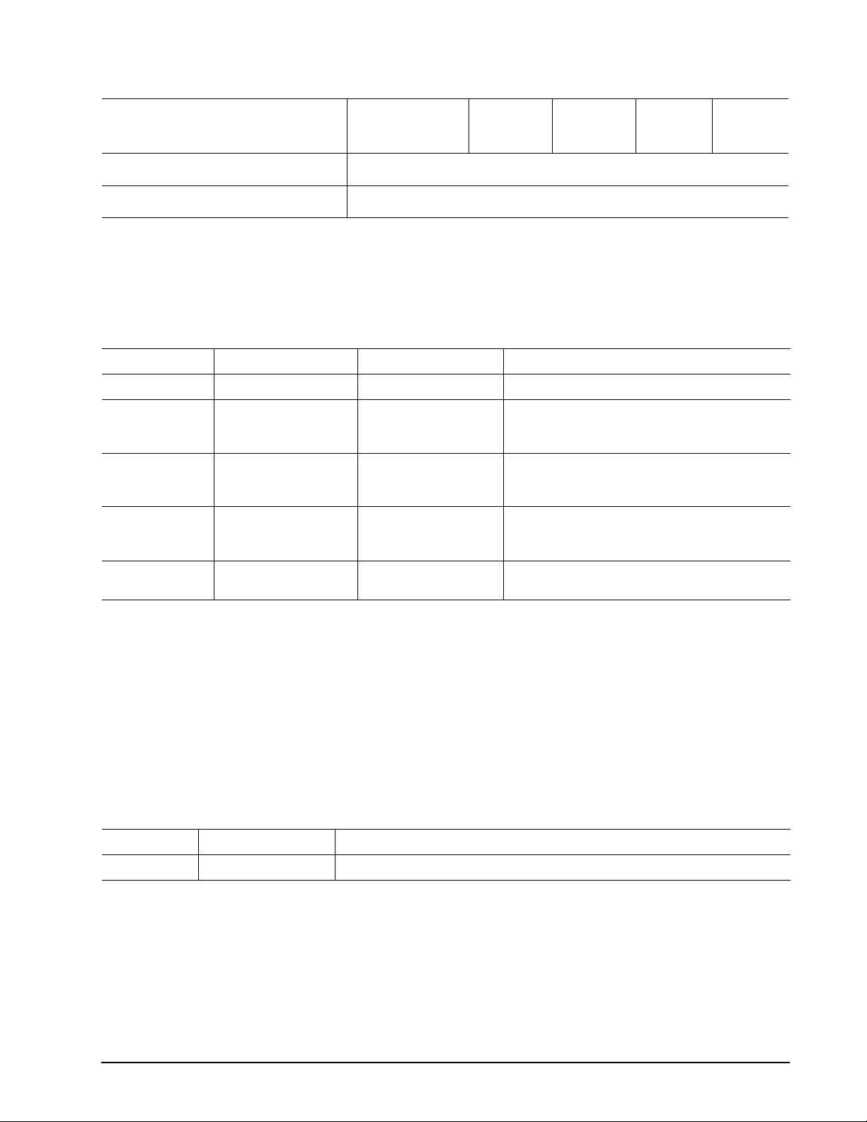
Table 2: Drive specifications
Drive specification ST3200822AS
Contact start-stop cycles
(25°C, 40% relative humidity)
Supports Hotplug operation per SATA II
specification
*One Gbyte equals one billion bytes when referring to hard drive capacity. Accessible capacity may vary depending on operating environment
and formatting.
**During periods of drive idle, some offline activity may occur according to the S .M.A.R.T. specification, which may increase acoustic and
power to operational levels.
50,000
Yes
ST3160827AS
ST3160023AS
ST3160021AS
ST3120827AS
ST3120026AS
ST3120022AS
ST380817AS
ST380013AS
ST380011AS
ST340111AS
ST340014AS
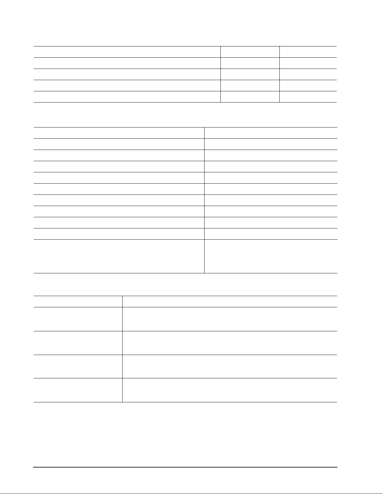
2.2 Formatted capacity
Model Formatted capacity* Guaranteed sectors Bytes per sector
ST3200822AS 200 Gbytes 390,721,968 512
ST3160827AS
ST3160023AS
ST3160021AS
ST3120827AS
ST3120026AS
ST3120022AS
ST380817AS
ST380013AS
ST380011AS
160 Gbytes 312,581,808 512
120 Gbytes 234,441,648 512
80 Gbytes 156,301,488 512
ST340111AS
ST340014AS
*One Gbyte equals one billion bytes when referring to hard drive capacity . Accessible capacity may vary depending on operating environment
and formatting.
40 Gbytes 78,165,360 512
2.2.1 LBA mode
When addressing these d rives in LBA mode, all bl ocks (sectors) are c onsecutively numbered fr om 0 to n–1,
where n is the number of guaranteed sectors as defined above.
See Section 4.3.1, "Id enti fy Devi ce co mmand" (words 60-61 a nd 1 00- 10 3) for a ddi tio nal in for ma tio n ab out 48bit addressing support of drives with capacities over 137 Gbytes.
2.3 Default logical geometry
Cylinders Read/write heads Sectors per track
16,383 16 63
LBA mode
When addressing these d rives in LBA mode, all bl ocks (sectors) are c onsecutively numbered fr om 0 to n–1,
where n is the number of guaranteed sectors as defined above.
Barracuda 7200.7 Serial ATA Product Manual, Rev. N 5
Page 14
2.4 Physical organization
Drive model Read/write heads Number of discs
ST3200822AS, ST3160827AS, ST3160023AS and ST3160021AS 4 2
ST3120827AS, ST3120026AS and ST3120022AS 3 2
ST380817AS, ST380013AS and ST380011AS 2 1
ST340111AS and ST340014AS 1 1
2.5 Recording and interface technology
Interface Serial ATA (SATA)
Recording method 16/17 EPRML
Recording density BPI (bits/inch max) 595,000 (671,500 on ST3200822AS model)
Track density TPI (tracks/inch max) 94,600 (98,000 on ST3200822AS model)
2
Areal density (Gbits/inch
Spindle speed (RPM) (± 0.2%) 7,200
Maximum Internal transfer rate (Mbytes/sec) 85.4
Sustained transfer rate OD (Mbytes/sec max) 58
max) 56.3 (68.5 on ST3200822AS model)
I/O data-transfer rate (Mbytes/sec max) 150 (SATA 1.0)
Interleave 1:1
Cache buffer
ST3200822AS, ST3160827AS, ST3160023AS, ST3120827AS,
ST3120026AS, ST380817AS, ST380013AS and ST340111AS
ST3160021AS, ST3120022AS, ST380011AS, and ST340014AS
8 Mbytes
2 Mbytes
2.5.1 Physical characteristics
Drive specification
Maximum height
(mm)
(inches)
Maximum width
(mm)
(inches)
Maximum lengt h
(mm)
(inches)
Typic al we ig ht
(grams)
(pounds)
26.035
1.028
101.6
4.00
146.99
5.787
635
1.4
6 Barracuda 7200.7 Serial ATA Product Manual, Rev. N
Page 15
2.6 Seek time
Seek measurements are taken with nominal power at 25°C ambient temperature. All times are measured using
drive diagnostics. The specifications in the table below are defined as follows:
• Track-to-track seek time is an average of all possible single-track seeks in both directions.
• Average seek time is a true statistical rand om average of at least 5,000 measure ments of seeks between
random tracks, less overhead.
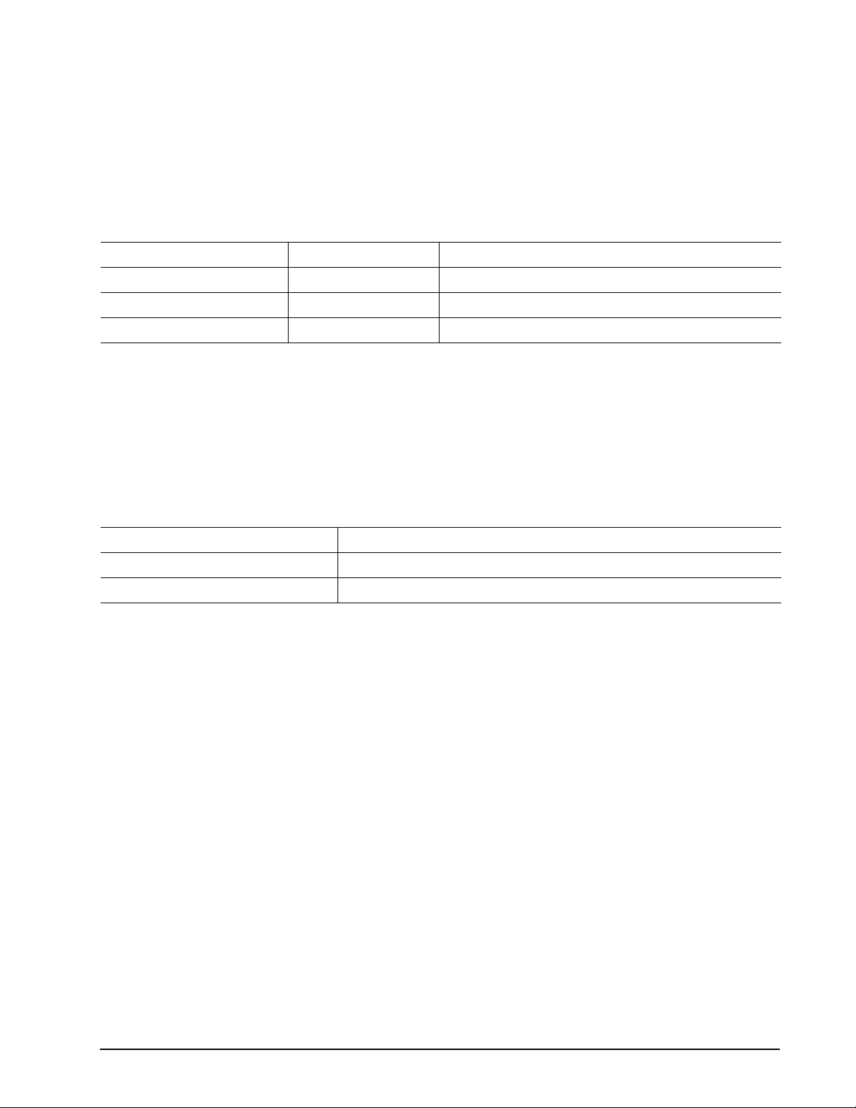
T able 3: Typical seek times
*Typical seek times (msec) Read Write
Track-to-track <1.0 <1.2
Average 8.5 9.5
Average latency 4.16 4.16
*Measured in performance mode
Note. These drives are designed to consistently meet the seek times represented in this manual. Physical
seeks, regardless of m ode (such as track-to-track and average), are expected to meet the noted
values. However, due to the manner in which these drives are formatted, benchmark tests that
include command overhead or measure logical s eeks may produce results that vary from these
specifications.
2.7 Start/stop times
Power-on to Ready (sec) 10 (max)
Standby to Ready (sec) 10 (max)
Ready to spindle stop (sec) 10 (max)
2.8 Power specifications
The drive receives DC power (+5V or +12V) through a native SATA power connector. See Figure 4 on page 20.
2.8.1 Power consumption
Power requirements for the drives are listed in the table on page 9. Typical power measurements are based on
an average of drives tested, under nomi nal conditions, using 5.0 V and 12.0V input vo ltage at 25°C ambient
temperature.
• Spinup power
Spinup power is measured from the tim e of power-on to the ti me that the drive sp indle reaches ope rating
speed.
• Seek mode
During seek mode, the read/wr ite actuator arm moves towar d a specific position on the disc s urface and
does not execute a read or write o peration . Servo el ectroni cs are active. S eek mode po wer repr esen ts the
worst-case power co nsump tion, us ing o nly ran dom s eeks with read or wr ite la tency ti me. This mode is no t
typical and is provided for worst-case information.
• Read/write power and current
Read/write power is measured with the heads on track, ba sed on a 16- sector write fo llowed by a 32-msec
delay, then a 16-sector read followed by a 32-msec delay.
Barracuda 7200.7 Serial ATA Product Manual, Rev. N 7
Page 16
• Operating power and current
Operating power is measured using 40 percent random seeks, 40 percent read/write mode (1 write for each
10 reads) and 20 percent drive idle mode.
• Idle mode power
Idle mode power is measured with the drive up to speed, with servo electronics active and with the heads in
a random track location.
• Standby mode
During Standby mode, the drive accep ts co mmands, b ut the driv e is not spi nning , and the se rvo and read /
write electronics are in power-down mode.
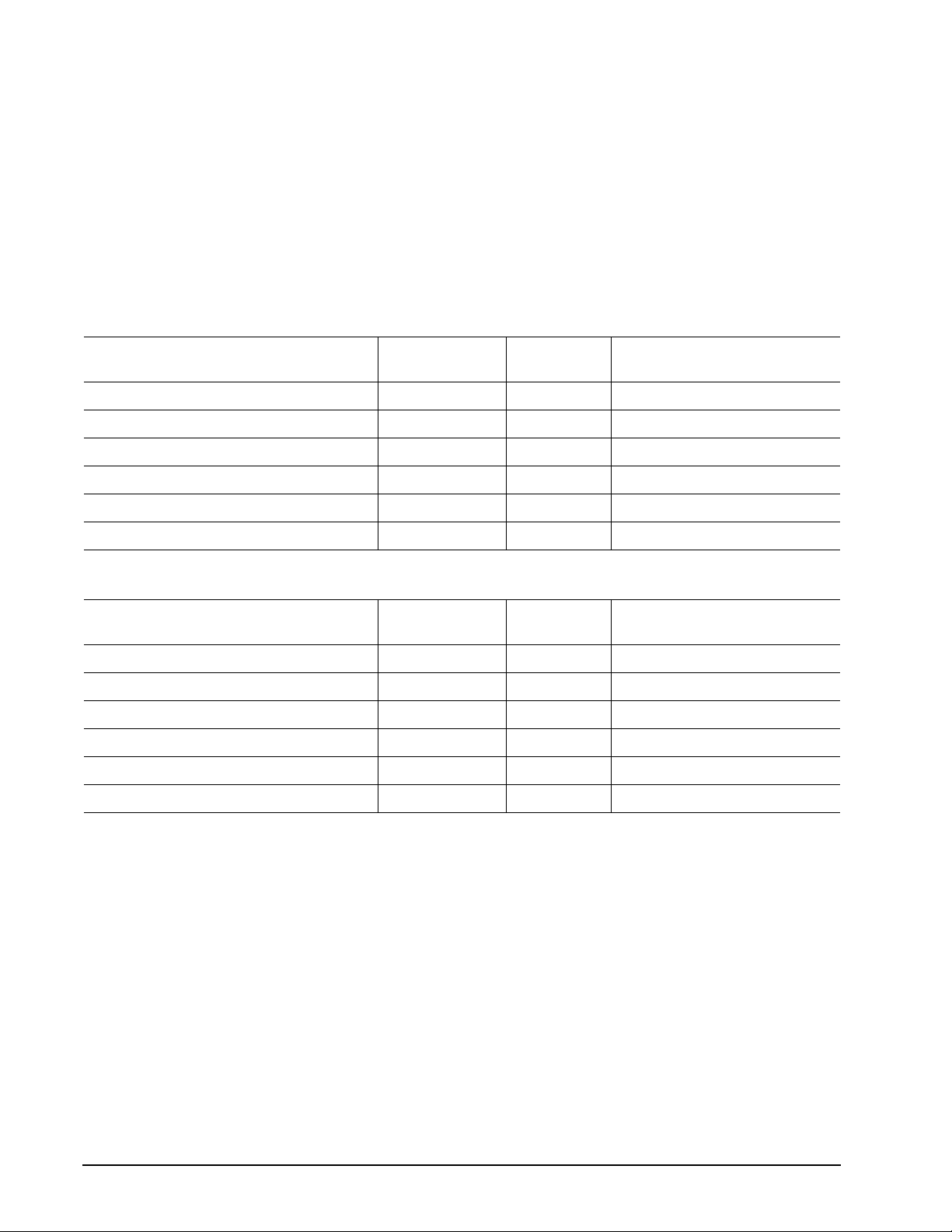
Table 4: DC power requirements (example of 160GB models supporting NCQ
Power dissipation (watts)
Spinup — — 2.8 (peak)
Idle 7.5 0.487 0.422
Idle (with offline activity)
Operating (40% r/w, 40% seek, 20% inop.) 12.0 0.631 0.737
Seeking 12.5 0.405 0.873
Standby/Sleep 1.0 0.185 0.006
[2]
Average
(watts, 25° C)
9.3 0.875 0.41
5V typ
amps
12V typ amps
[1]
)
Table 5: DC power requirements (example of 160GB and 200GB models not supporting NCQ)
Power dissipation (watts)
Spinup — — 2.8 (peak)
Idle 7.5 0.482 0.424
Idle (with offline activity)
Operating (40% r/w, 40% seek, 20% inop.) 12.1 0.638 0.739
[2]
Average
(watts, 25° C)
9.3 0.587 0.53
5V typ
amps
12V typ amps
Seeking 12.5 0.412 0.87
Standby/Sleep 2.0 0.367 0.014
[1] NCQ may not be enabled during power measurements.
[2] During periods of drive idle, some offline activity may occur according to the S.M.A.R.T. specification,
which may increase acoustic and power to operational levels.
8 Barracuda 7200.7 Serial ATA Product Manual, Rev. N
Page 17
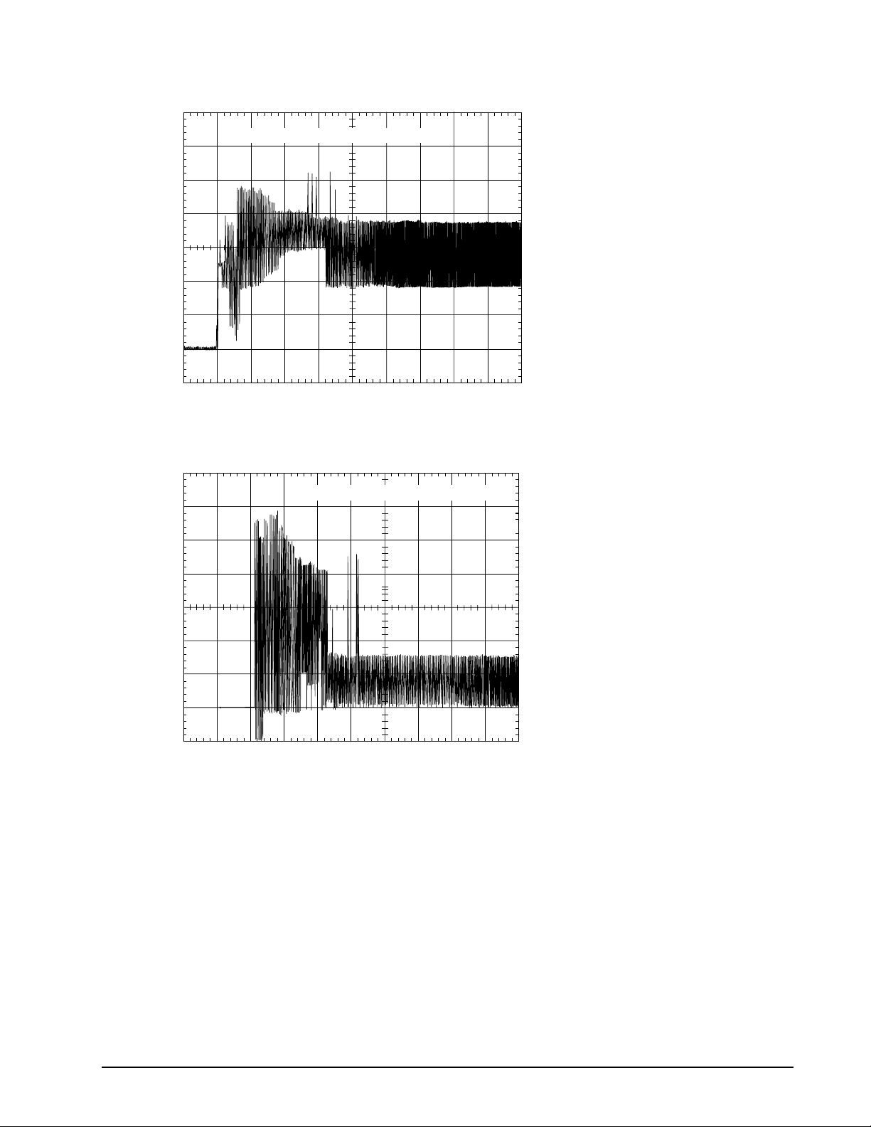
2.8.1.1 T ypical current profiles
A
A
8
1.50
1.25
1.00
mps
0.75
0.50
0.25
0.0
0.0 2 4 6 8 10 12 14 16
+5 Volt Current during spindle start — Typical Amperes
Seconds
Figure 1. Typical 5V startup and operation current profile
2.4
2.0
+12 Volt Current during spindle start — Typical Amperes
18
1.6
mps
1.2
0.8
0.4
0.0
0.0 2 4 6 8 10 12 14 16
Seconds
1
Figure 2. Typical 12V startup and operation current profile
2.8.2 Deferred spinup
Barracuda 7200.7 S erial ATA drives provide a deferred spi nup feature which storage sub system controllers
can use to sequence disc drive initializa tion. This is beneficial to systems which include m ultiple Serial ATA
hard disc drives beca use it allo ws subsystem c ontroll ers to stagger the spinup of ea ch drive to ac commodat e
available power supply current. This feature does not impact time-to-ready in typical desktop systems.
To accommodate the deferred spinup of multiple disc drives in an enclosure, Barracuda 7200.7 Serial ATA disc
drives will spin u p only after power is appl ied to the d rive and after s uccessful PHY (Physi cal layer) i nitialization. PHY initialization occurs after the PHY enters the DP7:DR_Ready state. This state is reached after a suc-
Barracuda 7200.7 Serial ATA Product Manual, Rev. N 9
Page 18

cessful exchange of Out-Of-Band (OOB) signals with a functional host-side Serial ATA port. In desktop
systems, SATA transceivers should initialize OOB as soon as power comes ready to guarantee the drive spins
up quickly. Seagate disc drives will not spin up without an operational host-side Serial ATA transceiver.
Additional details
Upon system power up, PHY commu nication is initiated with a COMRE SET signal, whic h is generated by the
host-side transcei ver. COMRESET is followed b y a COMINIT si gnal generated by t he disc drive tr ansceiver.
COMRESET and COMINIT a re follo w ed by an exchange of COMWAKE signals and Align pr im it iv es . The di sc
drive will spin up after the successful exchange of Align primitives cause the PHY to come ready.
For more details, refer to:
• Section 6.8 of the Serial ATA 1.0 High-Speed Serialized AT Attachment specification
• Section 6.2 of the Serial ATA II: Extensions to Serial ATA 1.0 specification
• SATA 1.0 design guides
Note. These specifications and guides are available on the Serial ATA web site (www.serialata.org).
2.8.3 Conducted noise
Input noise ripple is mea su red at the ho st system power supply acr o ss a n equ ival ent 80 -o hm r es isti ve load on
the +12 volt line or an equivalent 15-ohm resistive load on the +5 volt line.
• Using 12-volt power, the drive is expected to operate with a maximum of 120 mV peak-to-peak square-wave
injected noise at up to 10 MHz.
• Using 5-volt power, the drive is expect ed to ope rate wi th a maxi mum of 10 0 mV pe ak-t o-peak s quare- wave
injected noise at up to 10 MHz.
Note. Eq uivalent resistance is calculated by dividing the nom inal voltage by the typical RMS read/write
current.
2.8.4 Voltage tolerance
Voltage tolerance (including noise):
5V ± 5%
12V ± 10%
10 Barracuda 7200.7 Serial ATA Product Manual, Rev. N
Page 19

2.8.5 Power-management modes
The drive provides programmab le power mana gement to provide grea ter energy efficiency. In most systems,
you can control power management through the system setup program. The drive features the following
power-management modes :
Power modes Heads Spindle Buffer
Active Tracking Rotating Enabled
Idle Tracking Rotating Enabled
Standby Parked Stopped Enabled
Sleep Parked Stopped Disabled
• Active mode
The drive is in Active mode during the read/write and seek operations.
• Idle mode
The buffer remains enable d, and the d rive ac ce pts all com man ds and ret urns to Ac ti ve mode any tim e di sc
access is necessary.
• Standby mode
The drive enters Standby mode whe n the host sends a Standby Immediate command. If the host has set
the standby timer, the drive can also enter Standby mode automatically after the drive has been inactive for
a specifiable le ngth of time. The standby timer delay is established usi ng a Standby or Idle command. I n
Standby mode, the drive buffer is enabled, the heads are parked and the spindle is at rest. The drive
accepts all commands and returns to Active mode any time disc access is necessary.
• Sleep mode
The drive enters Sleep mode after receiving a Sle ep command from the host. In Sleep mode, the drive
buffer is disabled, the heads are park ed and the spindle is at rest. The drive l eaves Sleep mode after it
receives a Hard Re se t or So ft Rese t from the ho st. A fter recei ving a res et, the drive exits Sl eep m ode an d
enters Standby mode with all current translation parameters intact.
• Idle and Standby timers
Each time the d rive perf orms an Ac tive fun ction (rea d, write or seek), the standb y timer is reini tialized and
begins counting dow n from its specified de lay times to zero. If the standby timer reac hes zero before any
drive activity is requir ed , the dr iv e m ake s a transition to Standby mode. In both Idle and Standby mode, the
drive accepts all commands and returns to Active mode when disc access is necessary.
2.9 Environmental specifications
2.9.1 Ambient temperature
Ambient temperature is defined as the temperature of the environment immediately surrounding the drive.
Actual drive case tempe rature should not exceed 69°C (156°F) within the operating ambient conditions for
standard models, or 64°C (147°F) withi n the operating a mbient conditions for ST3200822 AS model. Rec ommended measurement locations are shown in See Figure 5 on page 22 .
Above 1,000 feet (305 meters), the ma ximum temperature is derated linearly to 112°F (44°C) at 10,000 feet
(3,048 meters).
Operating 0° to 60°C (32° to 140°F) for standard models
5° to 55°C (41° to 131°F) for ST3200822AS model
Nonoperating –40° to 70°C (–40° to 158°F)
Barracuda 7200.7 Serial ATA Product Manual, Rev. N 11
Page 20

2.9.2 T emperature gradient
Operating 20°C per hour (68°F per hour max), without condensation
Nonoperating 30°C per hour (86°F per hour max)
2.9.3 Humidity
2.9.3.1 Relative humidity
Operating 5% to 90% noncondensing (30% per hour max)
Nonoperating 5% to 95% noncondensing (30% per hour max)
2.9.3.2 Wet bulb temperature
Operating 33°C (91.4°F max)
Nonoperating 40.0°C (104°F max)
2.9.4 Altitude
Operating –60.96 m to 3,048 m (–200 ft to 10,000+ ft)
Nonoperating –60.96 m to 12,192 m (–200 ft to 40,000+ ft)
2.9.5 Shock
All shock specificat ions assume that the drive is mou nted securely with the input s hock applied at the drive
mounting screws. Shock may be applied in the X, Y or Z axis.
2.9.5.1 Operating shock
These drives compl y with the performance level s specified in this docu ment when subjected to a ma ximum
operating shock of 6 3 Gs based on half-sine sh ock pulses of 2 msec. S hocks should not be repeat ed more
than two times per second.
2.9.5.2 Nonoperating shock
The nonoperating s hock l evel that th e driv e can expe rience withou t incur ring ph ysic al d amage or degr adatio n
in performance when subsequently put into operation is 350 Gs based on a nonrepetitive half-sine shock pulse
of 2 msec duration.
12 Barracuda 7200.7 Serial ATA Product Manual, Rev. N
Page 21

2.9.6 Vibration
All vibration spec ifications assume that the drive is moun ted securely with the input vibration applied at the
drive mounting screws. Vibration may be applied in the X, Y or Z axis.
2.9.6.1 Operating vibration
The maximum vibrat ion levels th at the drive m ay exper ience whi le meeting the pe rforman ce standards sp ecified in this document are specified below.
5–22 Hz Limited displacement
23–350 Hz 0.5 G acceleration
2.9.6.2 Nonoperating vibration
The maximum nonoperating vibration levels that the drive may experience without incurring physical damage or degradation in performance when subsequently put into operation are specified below.
5–22 Hz Limited displacement
23–350 Hz 5.0 Gs
2.10 Acoustics
Drive acoustics a re measured as overall A -weighted acoustic soun d power levels (no pu re tones). All measurements are consistent with ISO document 7779. S ound power measureme nts are taken under essentially
free-field conditions over a reflecting plane. For all tests, the drive is oriented with the cover facing upward.
Note. For se ek mode tests, the drive is p laced in seek mode on ly. The number of seeks per second is
defined by the following equation:
(Number of seeks per second = 0.4 / (average latency + average access time)
Table 6: Fluid Dynamic Bearing (FDB) motor acoustics
Models Idle* Performance seek
ST3200822AS
ST3160827AS
ST3160023AS
ST3160021AS
ST3120827AS
ST3120026AS
ST3120022AS
ST380817AS
ST380013AS
ST380011AS
ST340111AS
ST340014AS
<2.5 bels (typ)
2.7 bels (max)
<2.2 bels (typ)
2.4 bels (max)
3.4 bels (typ)
3.7 bels (max)
3.1 bels (typ)
3.5 bels (max)
Note. During per iods of drive id le, some offline activi ty may occur accor ding to the S.M.A.R .T. specifica-
tion, which may increase acoustic and power to operational levels.
Barracuda 7200.7 Serial ATA Product Manual, Rev. N 13
Page 22

2.11 Electromagnetic immunity
When properly installed in a representative host system, the drive operates without err ors or degradation in
performance when subjected to the radio frequency (RF) environments defined in the following table:
Table 7: Radio frequency environments
Test Description Performance level Reference standard
Electrostatic discharge Contact, HCP, VCP: ± 4
Radiated RF immunity 80 to 1,000 MHz, 3 V/m,
80% AM with 1 kHz sine
900 MHz, 3 V/m, 5 0 % pu lse m od ula tion @
200 Hz
Electrical fast transient ± 1 kV on AC mains, ± 0.5 kV on external I/OB EN 61000-4-4: 95
Surge immunity ± 1 kV differential, ± 2 kV common, AC
mains
Conducted RF immunity 150 kHz to 80 MHz, 3 Vrms, 80% AM with
1 kHz sine
Voltage dips, interrupts 0% open, 5 seconds
0% short, 5 seconds
40%, 0.10 seconds
70%, 0.01 seconds
kV; Air: ± 8 kV B EN 61000-4-2: 95
A EN 61000-4-3: 96
B EN 61000-4-5: 95
A EN 61000-4-6: 97
C
C
C
B
ENV 50204: 95
EN 61000-4-11: 94
2.12 Reliability
14
Nonrecoverable read errors 1 per 10
Mean time between failures (MTBF) 600,000 power-on hours (nominal power, 25°C ambient temperature)
Contact start-stop cycles 50,000 cycles
(at nominal voltage and temperature, with 60 cycles per hour and a 50% duty
cycle)
bits read, max
Service Life 5 years.
Warranty To determine the warranty for a s pec ifi c d riv e, u se a web brow s er to ac ce ss the
Preventive maintenance None required.
follwoing web page:
www.seagate.com/support/service/
From this page, clic k on the “Verify Your Warran ty” link . You will be as ked to pro -
vide the drive ser ial nu mb er, model number (or part number) and c oun try of pu rchase.
The system will diplay the warranty information for your drive.
14 Barracuda 7200.7 Serial ATA Product Manual, Rev. N
Page 23

2.13 Agency certification
2.13.1 Safety certification
The drives are recogni ze d in ac co rd anc e with UL 1950 and CSA C22.2 (950 ) a nd m eet a ll appl icab le s ec ti ons
of IEC950 and EN 60950 as tested by TUV North America.
2.13.2 Electromagnetic compatibility
Hard drives that display the CE mark comply with the European Union (EU) requirements specified in the Electromagnetic Compatibili ty Directive (89/336/EE C). Testing is perfor med to the levels spec ified by the product
standards for Information Technology Equipment (ITE). Emission levels are defined by EN 55022, Class B and
the immunity levels are defined by EN 55024.
Seagate uses an independent laboratory to confirm compliance with the EC directives specified in the previous
paragraph. Drives are tested in representative end-user systems. Although CE-marked Seagate drives comply
with the directives wh en used in the test systems, we cannot guarantee t hat all systems will comply wit h the
directives. The drive is designed for operation inside a properly designed enclosure, with properly shielded I/O
cable (if necessary) and termi nators on all unu sed I/O ports. Compute r manufactu rers and syste m integrators
should confirm EMC compliance and provide CE marking for their products.
Korean RRL
If these drives have the Korea M inistry of Information a nd Comm unicatio n (MIC) log o, they co mply with paragraph 1 of Article 11 of the Electromagnetic Compatibili ty control Regulation and meet the Electr omagnetic
Compatibility (EMC) Framework req ui remen ts of the Radio Resear c h Labo rator y (RRL) Mini st ry of Informa tion
and Communication Republic of Korea.
These drives have been tested and comply with the Electromagnetic Interference/Electromagnetic Susceptibility (EMI/EMS) for Class B products. Drives are tested in a representative, end-user system by a Korean-recognized lab.
• EUT name (model numbers):ST3200822AS, ST3160827AS, ST3160023AS, ST3160021AS, ST3120827AS,
ST3120026AS, ST3120022AS, ST380817AS, ST380013AS, ST380011AS, ST340111AS and ST340014AS
• Certificate numbers ST3200822AS E-H011-04-0508 (B)
ST3160827AS E-H011-04-2274 (B)
ST3160023AS E-H011-03-0784 (B)
ST3160021AS E-H011-03-0783 (B)
ST3120827AS E-H011-04-2276 (B)
ST3120026AS E-H011-03-0788 (B)
ST3120022AS E-H011-03-0785 (B)
ST380817AS E-H011-04-2275 (B)
ST380013AS E-H011-03-0787 (B)
ST380011AS E-H011-03-0781 (B)
ST340111AS E-H011-03-0782 (B)
ST340014AS E-H011-03-0782 (B)
• Trade name or applicant: Seagate Technology International
• Manufacturing date: February 2003 for ST3160023AS, ST3160021AS, ST3120026AS, ST3120022AS,
ST380013AS, ST380011AS, and ST340014AS models.
• Manufacturing date: February 2004 for ST3200822AS models.
• Manufacturing date: February 2004 for ST3160827AS, ST3120827AS and ST380817AS models.
• Manufacturing date: February 2004 for ST340111AS models.
• Manufacturer/nationality: Singapore and China
Barracuda 7200.7 Serial ATA Product Manual, Rev. N 15
Page 24

Australian C-Tick (N176)
If these models h ave the C-Tick marki ng, th ey com ply wi th the Aus tralia/N ew Z ealand Standard AS/NZS 3548
1995 and meet the Electromagnetic Compatibility (EMC) Framework requirements of the Australian Communication Authority (ACA).
2.13.3 FCC verification
These drives are intended to be contained solely within a personal computer or similar enclosure (not attached
as an external device). As such, each drive is considered to be a subassembly even when it is individually marketed to the customer. As a subassembly, no Federal Communications Commission verificati on or ce rt ifi ca tio n
of the device is required.
Seagate Technology LLC has tested this device in enclosures as described above to ensure that the total
assembly (enclosure, dis c drive, motherboard, power supply, etc.) does comply with the limits for a Class B
computing device , pursuant to Subpa rt J, Part 15 of the FCC rules. Ope ration with no ncertified ass emblies is
likely to result in interference to radio and television reception.
Radio and television interferen ce. This equipment generates and uses radio frequ ency energy and if not
installed and used in strict accordance with th e manufacturer ’s instructions, may cause i nterference to radio
and television reception.
This equipment is designed to provide reasonable protection against such interference in a residential installation. However, there is no guarantee that interference will not occur in a particular installation. If this equipment
does cause interfer ence to radio or te levision, whic h can be determi ned by turning t he equipment on and off,
you are encouraged to try one or more of the following corrective measures:
• Reorient the receiving antenna.
• Move the device to one side or the other of the radio or TV.
• Move the device farther away from the radio or TV.
• Plug the computer into a different outlet so that the receiver and computer are on different branch outlets.
If necessary, you should consult your dealer or an experienced radio/tel evision technician for additional sug-
gestions. You may find helpful the following booklet prepared by the Federa l Communications Commission:
How to Identify and Resolve Radio-Television Interference Problems. This booklet is available from the Superintendent of Documents, U.S. Government Printing Office, Washington , DC 20402. Refer to public ation number 004-000-00345-4.
16 Barracuda 7200.7 Serial ATA Product Manual, Rev. N
Page 25

2.14 Environmental protection
Seagate designs its prod ucts to meet environ mental protectio n requirem ents worldwide, in cluding regul ations
restricting certain chemical substances.
European Union Restriction of Hazardous Substances (RoHS)
The European Union Restriction of Hazardous Substances (RoHS) Directive restricts the presence of chemical
substances, including Lead (Pb), in electronic products effective July 2006. Although amendments to the
Euro-pean Union’s Restri ction of Hazardous Substances (Ro HS) Direc ti ve ha ve not bee n fin ali z ed, to th e bes t
of our knowledge the disc drives documented in this publication will comply with the final RoHS Directive
require-ments.
A number of parts and materials in Seag ate products are procured from external suppl iers. We rely on the
rep-resentations of our suppliers regarding the presence of RoHS substances in these parts and materials. Our
supplier contracts r equire compliance with our chem ical substance restrictions, a nd our suppliers document
their compliance with our requirements by providing material content declarations for all parts and materials for
the disc drives documented in this publication. Current supplier declarations include disclosure of the inclusion
of any RoHS-regulated substance in such parts or materials.
Seagate also has internal systems in place to ensure ongoing compliance with the RoHS Directive and all laws
and regulations which restrict chemical content in electronic products. These systems include standard
operat-ing procedures that ensure that restricted su bstances are not utiliz ed in our manufacturi ng operations,
labora-tory analyti cal validatio n testing, and an internal auditing pr ocess to ens ure that all standar d operatin g
procedures are complied with.
2.15 Corrosive environment
Seagate electronic driv e components pass accelerated corr osion testing equivalent to 10 ye ars exposure to
light industrial envir onments containi ng sulfuro us gases, chlorine an d nitric oxide , classes G and H per ASTM
B845. However, this accelerated testing cannot duplicate every potential application environment. Users
should use caution exposing any electronic components to uncontrolled chemical pollutants and corrosive
chemicals as elec tronic drive componen t reliabi lity ca n be affected by th e installati on environm ent. The s ilver,
copper, nickel and gold films used in Seagate products are especially sensitive to the presence of sulfide, chloride, and nitrate contaminants. Sulfur is found to be the most damaging. In addition, electr onic components
should never be ex pose d to c ondensin g water on the surfac e of th e pri nted cir cuit bo ard a ssembly (PCBA ) or
exposed to an ambient relative humidity greater than 95%. Materials used in cabinet fabrication, such as vulcanized rubber, that can outgas corr osive compoun ds should be m inimized or e liminated. Th e useful life of any
electronic equipment may be extended by replacing materials near circuitry with sulfide-free alternatives.
Barracuda 7200.7 Serial ATA Product Manual, Rev. N 17
Page 26

18 Barracuda 7200.7 Serial ATA Product Manual, Rev. N
Page 27

3.0 Configuring and mounting the drive
This section contains the specifications and instructions for configuring and mounting the drive.
3.1 Handling and static-discharge precautions
After unpacking, and before installation, the dr ive may be ex posed to pote ntial handli ng and electros tatic discharge (ESD) hazards. Observe the following standard handling and static-discharge precautions:
Caution:
• The SeaShell™ replaces electrostatic discharge (ESD) bags. The SeaShell package is a shock-ribbed,
transparent clamshell enclosure that limits a drive’s exposure to ESD and also protects against external shocks
and stresses. The design permits attaching cables, software loading and label/barcode scanning without
removing the drive from the SeaShell. This minimizes handling damage. Keep the drive in the SeaShell
package until you are ready for installation.
• Before handling the drive, put on a grounded wrist strap, or ground yourself frequently by touching the metal
chassis of a computer that is plugged into a grounded outlet. Wear a grounded wrist strap throughout the entire
instal lation procedure.
• Handle the drive by its edges or frame only.
• The drive is extremely fragile—handle it with care. Do not press down on the drive top cover.
• Always rest the drive on a padded, antistatic surface until you mount it in the computer.
• Do not touch the connector pins or the printed circuit board.
• Do not remove the factory-installed labels from the drive or cover them with additional labels. Removal voids
the warranty. Some factory-installed labe ls c ontain inf ormati on nee ded to s ervic e the d riv e. Oth er label s ar e
used to seal out dirt and contamination.
Barracuda 7200.7 Serial ATA Product Manual, Rev. N 19
Page 28

3.2 Configuring the drive
(
S
Each drive on the Serial ATA interface connects in a point-to-point configuration with the Serial ATA host
adapter. There is no master/slav e relationship because each drive is consider ed a master in a point-to-point
relationships. If two dr ives are attach ed on one Ser ial ATA host adapter, the host operating system vi ews the
two devices as if they were both “masters” on two separate ports. This means both drives behave as if they are
Device 0 (master) devices.
Serial ATA drives are designed for easy installation with no jumpers, terminators, or other settings. It is not necessary to set any jumpers on this drive for proper operation. The jumper block adjacent to the signal connector
is for factory use only.
SATA Signal
Jumper Block
factory use only)
Figure 3. Serial ATA connectors
SATA Power
3.3 Serial ATA cables and connectors
The Serial ATA interface cable consists of four conductors i n two differential pairs, plu s three ground co nnections. The cable s ize may be 3 0 to 2 6 AWG with a m aximum length of on e m eter (3 9.37 inc hes). S ee Table 8
for connector pin definitions. Either end of the SATA signal cable can be attached to the drive or host.
For direct back plane co nnection , the dri ve connect ors ar e inserted directly into the h ost rec eptacle. The d rive
and the host recep tacle incorporate fe atures that enable the direct connec tion to be hot pl uggable and blin d
mateable.
For installations which require cables, you can connect the drive as illustrated in Figure 4.
Signal connector
Power connector
ignal cable
Power cable
Figure 4. Attaching SATA cabling
Each cable is keyed to ensure correct orientation.
20 Barracuda 7200.7 Serial ATA Product Manual, Rev. N
Page 29

3.4 Drive mounting
You can mount the drive in any o rientation u sing four s crews in the side -mountin g holes or four sc rews in th e
bottom-mounting holes. See Figure 5 on page 22 for drive mounting dimensions. Follow these important
mounting precautions when mounting the drive:
• Allow a minimum clearance of 0.030 inches (0.76 mm) around the entire perimeter of the drive for cooling.
• Use only 6-32 UNC mounting screws.
• The screws should be inserted no more than 0.150 inch (3.81 mm) into the bottom or side mounting holes.
• Do not overtighten the mounting screws (maximum torque: 6 inch-lb).
Barracuda 7200.7 Serial ATA Product Manual, Rev. N 21
Page 30

1.122
(
n
+ .020
(28.499
+ .508)
[1]
5.787 (146.9898) max.
1.638
(41.605)
[1]
[1]
4.000
(101.6)
[1]
4.000
(101.6)
Recommended
case temperature
measurement locatio
.250 + .015
(6.35 + .381)
(3x both sides)
.138
3.505)
1.028 max
(26.111 max)
.814
[1]
(20.676)
CLof conn. Datum B
2.00
(50.80)
CLof drive
Notes:
Dimensions are shown in inches (mm).
[1] Dimensions per SFF-8301 specification
[1]
2 x 3.750
(2 x 95.25)
2 x 1.625
(2 x 41.28)
2 x 1.750
(2 x 44.45)
[1]
[1]
4.000
(101.6)
[1]
Recommended
case temperature
measurement location
Figure 5. Mounting dimensions—top, side and end view
22 Barracuda 7200.7 Serial ATA Product Manual, Rev. N
Page 31

4.0 Serial ATA (SATA) interfac e
These drives use th e industr y-standard Serial ATA interface that sup ports FIS data transfe rs. It suppor ts ATA
programmed input/output (PIO) modes 0–4; multiword DMA modes 0–2, and Ultra DMA modes 0–6. The drive
also supports the use of the IORDY signal to provide reliable high-speed data transfers.
For detailed informa tion about the Serial ATA interface, refer to the “Serial ATA: High Speed Serialized AT
Attachment” specification.
4.1 Hot-Plug compatibility
Barracuda 7200.7 Serial ATA drives incorporate connectors which enable you to hot plug these drives in accordance with the Ser ial ATA: High Speed Serialized AT Attachment specificatio n revision 2. 0. This spec ification
can be downloaded from http://www.serialata.com.
Barracuda 7200.7 Serial ATA Product Manual, Rev. N 23
Page 32

4.2 Serial ATA device plug connector pin definitions
Table 8 summarizes the signals on the Serial ATA interface and power connectors.
Table 8: Serial ATA connector pin definitions
Segment Pin Function Definition
S1 Ground 2nd mate
S2 A+ Differential signal pair A from Phy
S3 AS4 Ground 2nd mate
S5 B- Differential signal pair B from Phy
S6 B+
Signal
S7 Ground 2nd mate
Key and spacing separate signal and power segments
Power
P1 V
P2 V
P3 V
33
33
33
3.3V power
3.3V power
3.3V power, pre-charge, 2nd mate
P4 Ground 1st mate
P5 Ground 2nd mate
P6 Ground 2nd mate
P7 V
P8 V
P9 V
5
5
5
5V power, pre-charge, 2nd mate
5V power
5V power
P10 Ground 2nd mate
P11 Reserved The pin corresponding to P11 in the backplane
receptacle connector is also reserved
The corresponding pin to be mated with P11 in
the power cable receptacle connector shall
always be grounded
P12 Ground 1st mate.
P13 V
P14 V
P15 V
12
12
12
12V power, pre-charge, 2nd mate
12V power
12V power
Notes:
1. All pins are in a single row, with a 1.27 mm (0.050”) pitch.
2. The commen ts on the mating sequ ence apply to the case of backplan e blindmate conn ector only. In this
case, the mating sequences are:
• the ground pins P4 and P12.
• the pre-charge power pints and the other ground pins.
• the signal pins and the rest of the power pins.
24 Barracuda 7200.7 Serial ATA Product Manual, Rev. N
Page 33

3. There are three power pins for each voltage. One pin from each voltage is used for pre-charge when
installed in a blind-mate backplane configuration.
4. All used voltage pins (V
) must be terminated.
x
Barracuda 7200.7 Serial ATA Product Manual, Rev. N 25
Page 34

4.3 Supported ATA commands
The following table lists Serial ATA standard comma nds that the drive supports. For a detailed description of
the ATA commands, refer to the Serial ATA: High Speed Serialized AT Attachment specification. See
“S.M.A.R.T. commands” on page 33.for details and subcommands used in the S.M.A.R.T. implementation.
Command name Command code (in hex)
ATA-standard commands
Download Microcode 92h
Execute Device Diagnostics 90h
Flush Cache E7h
Flush Cache Extended EAh
Identify Device ECh
Initialize Device Parameters 91h
Read Buffer E4h
Read DMA C8h
Read DMA Extended 25h
Read DMA without Retries C9h
Read Multiple C4h
Read Multiple Extended 29h
Read Native Max Address F8h
Read Native Max Address Extended 27h
Read Sectors 20h
Read Sectors Extended 24h
Read Sectors without Retries 21h
Read Verify Sectors 40h
Read Verify Sectors Extended 42h
Read Verify Sectors without Retries 41h
Seek 70h
Set Features EFh
Set Max Address F9h
Note: Individual Set Max commands are
identified by the value placed in th e Set Max
Features register as defined to the right.
Address:
Password:
Lock:
Unlock:
Freeze Lock:
Set Multiple Mode C6h
00
01
02
03
04
H
H
H
H
H
S.M.A.R.T. B0h
Write Buffer E8h
Write DMA CAh
Write DMA Extended 35h
26 Barracuda 7200.7 Serial ATA Product Manual, Rev. N
Page 35

Command name Command code (in hex)
Write DMA without Retries CBh
Write Multiple C5h
Write Multiple Extended 39h
Write Sectors 30h, 31h
Write Sectors Extended 34h
ATA-standard power-management commands
Check Pow er Mode 98h or E5h
Idle 97h or E3h
Idle Immediate 95h or E1h
Sleep 99h or E6h
Standby 96h or E2h
Standby Immediate 94h or E0h
ATA-standard security commands
Security Set Password F1h
Security Unlock F2h
Security Erase Prepare F3h
Security Erase Unit F4h
Security Freeze Lock F5h
Security Disable Password F6h
Barracuda 7200.7 Serial ATA Product Manual, Rev. N 27
Page 36

4.3.1 Identify Device command
The Identify Device command (command code EC
) transfers information about the drive to the host following
H
power up. The data is o rg ani ze d a s a sin gle 512-byte block of data, who se c onte nts are shown in the table on
page 27. All reserved bits or words s hould be set to zero. Parameter s listed with an “x” are drive-sp ecific or
vary with the state of the drive. See Section 2.0 on page 3 for default parameter settings.
The following comm ands contain drive-specifi c features t hat may not be include d in the Se rial ATA specification.
Word Description Value
Configuration informa tio n:
• Bit 15: 0 = ATA; 1 = ATAPI
0
• Bit 7: removable media
• Bit 6: removable controller
• Bit 0: reserved
1 Number of logical cylinders 16,383
2 ATA-reserved 0000
3 Number of logical heads 16
4 Retired 0000
5 Retired 0000
6 Number of logical sectors per logical track: 63 003F
7–9 Retired 0000
10–
Serial number: (20 ASCII characters, 0000H = none) ASCII
19
0C5A
H
H
H
H
H
H
20 Retired 0000
21 Retired 0400
22 Obsolete 0000
23–
26
27–
46
Firmware revision (8 ASCII character string, padded with blanks to end of
string)
Drive model number: (40 ASCII characters, padded with blanks to end of
string)
x.xx
ST3200822AS
ST3160827AS
ST3160023AS
ST3160021AS
ST3120827AS
ST3120026AS
ST3120022AS
ST380817AS
ST380013AS
ST380011AS
ST340111AS
ST340014AS
47 (Bits 7–0) Maximum sectors per interrupt on Read multiple and Write mul-
8010
tiple (16)
48 Reserved 0000
49 Standard Standby timer, IORDY supported and may be disabled 2F00
50 ATA-reserved 0000
51 PIO data-transfer cycle timing mode 0200
52 Retired 0200
H
H
H
H
H
H
H
H
H
28 Barracuda 7200.7 Serial ATA Product Manual, Rev. N
Page 37

Word Description Value
53 Words 54–58, 64–70 and 88 are valid 0007
54 Number of current logical cylinders xxxx
55 Number of current logical heads xxxx
56 Number of current logical sectors per logical track xxxx
57–
Current capacity in sectors xxxx
58
59 Number of sectors transferred during a Read Multiple or Write Multiple
xxxx
command
60–
61
Total number of user-addressable LBA sectors available
(see Section 2.2 for related information)
*Note: The maximum value allowed in this field is: 0FFFFFFFh
(268,435,455 sectors, 137 Gbytes). Drives with capacities over 137
Gbytes will have 0FFFFFFFh in this field and the actual number of useraddressable LBAs specified in words 100-103. This is required for drives
that support the 48-bit addressing feature.
ST3200822AS = 0FFFFFFFh*
ST3160827AS = 0FFFFFFFh*
ST3160023AS = 0FFFFFFFh*
ST3160021AS = 0FFFFFFFh*
ST3120827AS = 234,441,648
ST3120026AS = 234,441,648
ST3120022AS = 234,441,648
ST380817AS = 156,301,488
ST380013AS = 156,301,488
ST380011AS = 156,301,488
ST340111AS = 78,165,360
ST340014AS = 78,165,360
62 Retired 0000
63 Multiword DMA active an d m od es su pp orted (s ee note following this table) xx07
64 Advanced PIO modes supported (modes 3 and 4 supported) 0003
65 Minimum multiword DMA transfer cycle time per word (120 nsec) 0078
66 Recommended multiword DMA transfer cycle time per word ( 120 nsec) 0078
67 Minim um PIO cycle time without IORDY flow control (240 nsec) 00F0
68 Minimum PIO cycle time with IORDY flow control ( 120 nsec) 0078
69–
ATA-reserved 0000
74
H
H
H
H
H
H
H
H
H
H
H
H
H
H
75 Queue depth 0000
76–
ATA-reserved 0000
79
80 Major version number 003E
81 Minor version number 0000
82 Command sets supported 306B
83 Command sets supported 4001
84 Command sets support extension 4000
85 Command sets enabled 30xx
86 Command sets enabled 0001
87 Command sets enable extension 4000
88 Ultra DMA support and current mode (see note following this table) xx3F
89 Security erase time 0000
H
H
H
H
H
H
H
H
H
H
H
H
Barracuda 7200.7 Serial ATA Product Manual, Rev. N 29
Page 38

Word Description Value
90 Enhanced security erase time 0000
92 Master password revision code FFFE
93 Hardware reset value
xxxx
(see description following this table)
94 Auto acoustic management setting xxxx
95–
ATA-reserved 0000
99
100–
103
Total number of user-addressable LBA sectors available
(see Section 2.2 for related information)
These words are required fo r drives that s upport th e 48-bit ad dressi ng fea-
ture. Maximum value: 0000FFFFFFFFFFFFh.
ST3200822AS = 390,721,968
ST3160827AS = 312,581,808
ST3160023AS = 312,581,808
ST3160021AS = 312,581,808
ST3120827AS = 234,441,648
ST3120026AS = 234,441,648
ST3120022AS = 234,441,648
ST380817AS = 156,301,488
ST380013AS = 156,301,488
ST380011AS = 156,301,488
ST340111AS = 78,165,360
ST340014AS = 78,165,360
104–
ATA-reserved 0000
127
128 Security status 0001
129–
Seagate-reserved xxxx
159
H
H
H
H
H
H
H
H
160–
254
255 Integrity word xxA5
ATA-reserved 0000
H
H
Note. Advanced Power Management (APM) and Au tomati c Acoustic Mana gemen t (AAM) featu res are n ot supp orted
Note. See the bit descriptions below for words 63, 88, and 93 of the Identify Drive data.
30 Barracuda 7200.7 Serial ATA Product Manual, Rev. N
Page 39

Description (if bit is set to 1)
Bit Word 63
0 Multiword DMA mode 0 is supported.
1 Multiword DMA mode 1 is supported.
2 Multiword DMA mode 2 is supported.
8 Multiword DMA mode 0 is currently active .
9 Multiword DMA mode 1 is currently active .
10 Multiword DMA mode 2 is currently active.
Bit Word 88
0 Ultra DMA mode 0 is supported.
1 Ultra DMA mode 1 is supported.
2 Ultra DMA mode 2 is supported.
3 Ultra DMA mode 3 is supported.
4 Ultra DMA mode 4 is supported.
8 Ultra DMA mode 0 is currently active.
9 Ultra DMA mode 1 is currently active.
10 Ultra DMA mode 2 is currently active.
11 Ultra DMA mode 3 is currently active.
12 Ultra DMA mode 4 is currently active.
13 Ultra DMA mode 5 is currently active.
Bit Word 93
13 1 = 80-conductor cable detected, CBLID above V
0 = 40-conductor cable detected, CBLID below VIL
IH
Barracuda 7200.7 Serial ATA Product Manual, Rev. N 31
Page 40

4.3.2 Set Features command
This command controls the implementation of various features that the drive supports. When the drive receives
this command, it sets BSY, checks the contents of the Features re gister, clears BSY and generates an interrupt. If the value in the register does not represent a fea ture that the driv e supports, the comman d is aborted .
Power-on default has the rea d look-ahe ad and wr ite cach ing featur es enabled . The ac ceptable va lues for the
Features register are defined as follows:
Table 9: Set Features command values
02
03
Enable write cache (default).
H
Set transfer mode (based on value in Sector Count register).
H
Sector Count register values:
00
Set PIO mode to default (PIO mode 2).
H
01
Set PIO mode to default and disable IORDY (PIO mode 2).
H
08HPIO mode 0
09
PIO mode 1
H
0A
PIO mode 2
H
0BHPIO mode 3
0C
PIO mode 4 (default)
H
20
Multiword DMA mode 0
H
21HMultiword DMA mode 1
22
Multiword DMA mode 2
H
40
Ultra DMA mode 0
H
41HUltra DMA mode 1
42
Ultra DMA mode 2
H
43
Ultra DMA mode 3
H
44HUltra DMA mode 4
45
Ultra DMA mode 5
H
55
82
AA
F1
Disable read look-ahead (read cache) feature.
H
Disable write cache
H
Enable read look-ahead (read cache) feature (default).
H
Report full capacity available
H
Note. At powe r-on, or after a hardware or software r eset, the default values of t he features are as indi-
cated above.
32 Barracuda 7200.7 Serial ATA Product Manual, Rev. N
Page 41

4.3.3 S. M.A.R.T. commands
S.M.A.R.T. provides near-ter m failure prediction for disc driv es. When S.M.A.R.T. is enable d, the drive monitors predetermined driv e attr i bute s tha t are susceptible t o d egrad ati on ov er time. If self-monitoring determines
that a failure is likely, S.M.A.R.T. makes a status report available to t he host. Not all failure s are predictable.
S.M.A.R.T. predictability i s limited to the attrib utes the drive can moni tor. For more information on S.M.A.R.T.
commands and implementation, see the Draft ATA-5 Standard.
SeaTools diagnostic software a ctiva tes a b uilt- in driv e sel f-test ( DST S .M.A.R .T. command for D4
) that elimi-
H
nates unnecessary drive returns. The diagnostic software ships with all new drives and is also available at:
http://seatools.sea
gate.com.
This drive is shipped with S.M.A.R.T. features disabled. Y ou must have a recent BIOS or software package that
supports S.M.A.R.T. to enable this feature. The table below shows the S.M.A.R.T. command c odes that the
drive uses.
Table 10: S.M.A.R.T. commands
Code in features register S.M.A.R.T. command
D0
D1
D2
D3
D4
D5
D6
D7
D8
D9
DA
H
H
H
H
H
H
H
H
H
H
H
S.M.A.R.T. Read Data
Vendor-specific
S.M.A.R.T. Enable/Disable Attribute Autosave
S.M.A.R.T. Save Attribute Values
S.M.A.R.T. Execute Off-line Immediate
(runs DST)
S.M.A.R.T. Read Log Sector
S.M.A.R.T. Write Log Sector
Vendor-specific
S.M.A.R.T. Enable Operations
S.M.A.R.T. Disable Operations
S.M.A.R.T. Return Status
Note. If an appropr iate code is not written to the Features Regi ster, the command is aborted and 0x04
(abort) is written to the Error register.
Barracuda 7200.7 Serial ATA Product Manual, Rev. N 33
Page 42

34 Barracuda 7200.7 Serial ATA Product Manual, Rev. N
Page 43

5.0 Seagate Technology support services
Online services
Internet
www.seagate.com for informatio n about Seagate products and servic es. Worldwide support is availab le 24
hours daily by e-mail for your questions.
Presales Support: www.sea
Technical Support: www.sea
gate.com/support/email/email_presales.html or Presales@Seagate.com
gate.com/support/email/email_disc_support.html or DiscSupport@Seagate.com
mySeagate
my.seagate.com is the industry’s firs t Web portal designed specific ally for OEMs and di stributors. It provi des
self-service a ccess to cr itical app lications, personaliz ed content and the tool s that allo w our partner s to manage their Seagate account fun ctions. Submit prici ng requests, order s and returns through a singl e, passwordprotected Web interface—anytime, anywhere in the world.
reseller.seagate.com
reseller.seagate.com supports Seag ate resellers with produc t information, program benefi ts and sales tools.
You may register fo r customized communication s that are not available on the web . These communications
contain product la unch, EOL, pr icing, prom otions and oth er channel- related inf ormation. To learn more about
the benefits or to register, go to reseller.sea
gate.com, any time, from anywhere in the world.
Automated phone services
SeaFONE® (1-800-SEAGATE) is the Seagate toll-free number (1-800-732-4283) to access our automated
directory assistance for Seagate Service Center support options. International callers can reach this service by
dialing +1-405-324-477 0.
Seagate Service Centers
Presales Support
Our Presales Suppo rt staff can help you deter mine which Seagate products are best suited for your specific
application or computer system, as well as drive availability and compatibility.
Technical Support
If you need help installing your dr ive, consult your system's doc ume ntation or contact the deal er's s upp ort ser vices department for assista nce specific to your sy stem. Seagate techn ical support is also av ailable to assist
you online at support.sea
tion and your drive’s “ST” model number available.
SeaTDD™ (+1-405-324-3655) is a telecommuni catio ns de vice for the d eaf ( TDD). You can send questions or
comments 24 hours d aily and e xcha nge m essag es wi th a technic al s upport speci alist during nor mal b usine ss
hours for the call center in your region.
Barracuda 7200.7 Serial ATA Product Manual, Rev. N 35
gate.com or through one of our call centers. Have your system configuration informa-
Page 44

Customer Service Operations
Warranty Service
Seagate offers worldwide customer supp ort for Seagate drives. Seagate dis tributors, OEMs and other direct
customers should contact their Seagate Customer Service Operations (CSO) representative for warrantyrelated issues. Resell ers or end users of drive products should contact their plac e of purchase or one of th e
Seagate CSO warranty center s for ass istance. Have your drive’s “ST” mod el numbe r and serial nu mber av ailable.
Data Recovery Services
Seagate offers data recovery services for all formats and all brands of storage media. Our Data Recovery Services labs are currently located in North America. To get a free quick quote or speak with a case management
representative, call 1-800-475-0143. Additional information, including an online request form and data loss prevention resources, is available at www.datarecovery.sea
gate.com.
Authorized Service Centers
In some locations outside the US, you can contact an Authorized Service Center for service.
USA/Canada/Latin America support services
Seagate Service Centers
Presales Support
Call center T oll-free Direct dial FAX
Americas 1-877-271-3285
1
+1-405-324-4730
1
+1-405-324-4704
Technical Support
Call center T oll-free Direct dial FAX
Americas 1-800-SEAGATE
2
+1-405-324-4700
2
+1-405-324-3339
Customer Service Operations
Warranty Service
Call center Toll-free Direct dial FAX / E-mail
USA, Canada, Mexico and 1-800-468-3472
Latin America
Brazil
Jabil Industrial Do Brasil — +55-11-4191-4761 +55-11-4191-5084
4
LTDA
Data Recovery Services
Call center T oll-free Direct dial FAX
USA, Canada, 1-800-475-01435 +1-905-474-2162 1-800-475-0158
and Mexico +1-905-474-2459
1
Hours of operation are 8:00 A.M. to 11:45 A.M. and 1:00 P.M. to 6:00 P.M., Monday through Friday (Central time).
2
Hours of operation are 8:00 A.M. to 8:00 P.M., Monday through Friday (Central time).
3
Hours of operation are 8:00 A.M. to 5:00 P.M., Monday through Friday (Central time).
4
Authorized Service Center
5
Hours of operation are 8:00 A.M. to 8:00 P.M., Monday through Friday, and 9:00 A.M. to 5:00 P.M., Saturday (Eastern time).
3
— +1-956-664-4725
SeagateRMA.br@jabil.com
36 Barracuda 7200.7 Serial ATA Product Manual, Rev. N
Page 45

European support services
For presales and technic al support in Europe , dial the Seagate Serv ice Center toll-free nu mber for your specific location. If yo ur location is not listed h ere, dial our presales and tech nical support call cen ter at +1-405324-4714 from 8:00
A.M. to 11:45 A.M. and 1:00 P.M. to 5:00 P.M. (Central Europe time) Monday through Friday.
The presales and technical support call center is located in Oklahoma City, USA.
For European warranty service , dial the tol l-free numb er for you r specific locatio n. If your l ocation is not liste d
here, dial our Euro pean CS O warr an ty ce nter at +31-20-316-7222 from 8:30
A.M. to 5:00 P.M. (Central Europ e
time) Monday through Friday. The CSO warranty center is located in Amsterdam, The Netherlands.
Seagate Service Centers
Toll-free support numbers
Call center Presales and Technical Support Warranty Service
Austria — 00 800-47324289
Belgium 00 800-47324283 (00 800-4SEAGATE) 00 800-47324289
Denmark 00 800-47324283 00 800-47324289
France 00 800-47324283 00 800-47324289
Germany 00 800-47324283 00 800-47324289
Ireland 00 800-47324283 00 800-47324289
Italy 00 800-47324283 00 800-47324289
Netherlands 00 800-47324283 00 800-47324289
Norway 00 800-47324283 00 800-47324289
Poland 00 800-311 12 38 00 800-311 12 38
Spain 00 800-47324283 00 800-47324289
Sweden 00 800-47324283 00 800-47324289
Switzerland 00 800-47324283 00 800-47324289
Turkey 00 800-31 92 91 40 00 800-31 92 91 40
United Kingdom 00 800-47324283 00 800-47324289
FAX services—All Europe (toll call)
Technical Support +1-405-324-3339
Warranty Service +31-20-653-3513
Africa/Middle East support services
For presales and tec hnical suppo rt in Africa and the Midd le East, dia l our presal es and technic al support c all
center at +1-405-32 4-471 4 from 8:00
day through Friday. The presales and technical support call center is located in Oklahoma City, USA.
For warranty service in Africa and the Middle East, dial our Euro pean CSO warranty center at +31-20-3167222 from 8:30
A.M. to 5:00 P.M. (Centr al Euro pe time ) Mond ay throu gh Frid ay, or send a FAX to +31-20-653-
3513. The CSO warranty center is located in Amsterdam, The Netherlands.
A.M. to 11:45 A.M. and 1:00 P.M. to 5:00 P.M. (Central Europe time) Mon-
Barracuda 7200.7 Serial ATA Product Manual, Rev. N 37
Page 46

Asia/Pacific support services
For Asia/Pacific pr esales and technical s upport, dial the toll-fre e number for your specific location. The Asia /
Pacific toll-free numbers are available from 6:00
ern time) Monday through Friday , except as noted. If your location is not listed here, direct dial one of our technical support locations.
A.M. to 10:45 A.M. and 12:00 P.M. to 6:00 P.M. (Australian East-
Warranty service is availabl e from 9:00
A.M. to 6:00 P.M. April throu gh October, and 10:00 A.M. to 7:00 P.M.
November through March (Australian Eastern time) Monday through Friday.
Seagate Service Centers
Call center Toll-free Direct dial FAX
Australia 1800-14-7201 — —
China (Mandarin)
Hong Kong 800-90-0474 — —
Hong Kong (Cantonese)
2, 4
India
1, 4
800-810-9668 +86-10-6225-5336 —
1, 4
001-800-0830-1730 — —
1-600-180-1104 — —
Indonesia 001-803-1-003-2165 — —
3, 4
Japan
Korea
3, 4
0034 800 400 554 — —
007 98 8521 7635 — —
Malaysia 1-800-80-2335 — —
New Zealand 0800-443988 — —
Singapore 800-1101-150 — +65-6488-7525
Taiwan (Mandarin)
1, 4
00-800-0830-1730 — —
Thailand 001-800-11-0032165 — —
Customer Service Operations
Warranty Service
Call center Toll-free Direct dial FAX
Asia/Pacific — +65-6485-3595 +65-6485-4860
Australia 1800-12-9277 — —
4
India
— +91-44-821-6164 +91-44-827-2461
1
Hours of operation are 8:30 A.M. to 5:30 P.M., Monday through Friday (Australian Western time).
2
Hours of operation are 9:00 A.M. to 6:00 P.M., Monday through Saturday.
3
Hours of operation are 9:30 A.M. to 6:30 P.M., Monday through Friday.
4
Authorized Service Center
38 Barracuda 7200.7 Serial ATA Product Manual, Rev. N
Page 47

Publication feedback surv ey
We are interested in your comm ents and su ggesti ons rega rding this pu blic ation. P lease take a few minu tes to
participate in our survey at the following URL:
http://survey.seagate.com/survey/techpubs.nsf
Thank you for your time and comments.
Barracuda 7200.7 Serial ATA Product Manual, Rev. N 39
Page 48

40 Barracuda 7200.7 Serial ATA Product Manual, Rev. N
Page 49

Index
A
ACA 16
acoustics
Active
Active mode
actuator arm
Address
Agency certification
Altitude
Altitude, nonoperating
Altitude, operating
Ambient temperature
ambient temperature
Areal density
areal density
ATA commands
ATA data-transfer modes supported
Australia/New Zealand Standard AS/NZS3548 1995
Australian Communication Authority (ACA)
Australian C-Tick
Average latency
Average seek time
Average seek, read
Average seek, write
B
bels 4
BPI
buffer
Bytes per sector
C
cables and connectors 20
Cache
capacity
case temperature
CE mark
certification
Check Power Mode
Class B computing device
compatibility
Conducted noise
Conducted RF immunity
Configuring the drive
connectors
Corrosive environment
CSA C22.2 (950)
current
cycles
Cylinders
4, 13
11
11
7
26
15
12
4
4
4, 11
7
3, 6
1
26
3
16
16
16
7
7
4
4
3
3, 6
3, 5
3, 6
5
11
15
15
27
16
15
10
14
19
20
17
15
4
14
5
cylinders
3
D
data-transfer rates 1
DC power
Default logical geometry
Default sectors per track
density
Diagnostics
dimensions
disc surface
Discs
Download Microcode
7
5
3
3
26
22
7
3
26
E
Electrical fast transient 14
Electromagnetic compatibility
Electromagnetic Compatibility (EMC)
Electromagnetic Compatibility control Regulation
Electromagnetic Compatibility Directive (89/336/EEC)
15
Electromagnetic immunity
Electrostatic discharge
electrostatic discharge (ESD)
EN 55022, Class B
EN 55024
EN 60950
Environmental specifications
EPRML
error-correction algorithms
errors
ESD
EU
15
European Union (EU) requirements
Execute Device Diagnostics
15
15
1, 6
4, 14
19
15
15
15
15
14
14
19
11
1
15
26
F
FCC verification 16
features
Federal Communications Commission
Flush Cache
Flush Cache Extended
Formatted capacity
Formatted Gbytes
1
16
26
26
5
3
G
Gbytes 5
geometry
gradient
Gs
Guaranteed sectors
guaranteed sectors
5
4
13
3, 5
5
Barracuda 7200.7 Serial ATA Product Manual, Rev. N 41
Page 50

H
Handling precautions 19
heads
3, 5
Height
3
Humidity
humidity
12
4
I
I/O data-transfer rate 3, 6
Identify Device
Identify Device command
Idle
8, 11, 27
Idle Immediate
Idle mode
IEC950
Information Technology Equi pm ent (ITE )
Initialize Device Parameters
Input noise ripple
input voltage
Interface
interface
Interleave
Internal data transfer rate
Internal data-transfer rate
ISO document 7779
ITE
15
15
26
28
27
4, 8, 11
15
26
10
7
6
23
6
3
6
13
K
Korea Ministry of Information and Communication
(MIC)
15
Korean RRL
15
L
latency 4, 7
latency time
LBA mode
Length
logical geometry
7
5
3
5
M
magnetoresistive (GMR) recording heads 1
maintenance
master/slave
Max Address
maximum temperature
Mean time between failures
Mean time between failures (MTBF)
measurement locations
MIC
15
Microcode
mounting
mounting screws
mounting the drive
14
2
26
11
4
14
11
26
21
12
19
MTBF
14
N
native command queuing 2
NCQ
2
noise
10
nominal power
Nonoperating shock
Nonoperating vibration
Nonrecoverable read errors
7
12
13
4, 14
O
Operating 8
Operating power
Operating shock
Operating vibration
4, 8
12
13
P
Physical characteristics 6
Physical organization
Physical read/write heads
point-to-point
Power consumption
power consumption
Power dissipation
Power modes
Power specifications
Power-management modes
Power-on to Ready
Power-on to ready
precautions
printed circuit board
programmable power management
2, 20
11
19
6
3
7
7
8
7
11
7
4
19
Q
quick reference 3
R
Radiated RF immunity 14
Radio and television interferen ce
radio frequency (RF)
random seeks
Read Buffer
Read DMA
Read DMA Extended
Read DMA without Retries
read errors
Read Multiple
Read Multiple Extended
Read Native Max Address
Read Native Max Address Extended
Read Sectors
Read Sectors Extended
26
26
4, 14
14
7, 8
26
26
26
26
26
16
26
26
11
26
42 Barracuda 7200.7 Serial ATA Product Manual, Rev. N
Page 51

Read Sectors without Retries 26
Read Verify Sectors
Read Verify Sectors Extended
Read Verify Sectors without Retries
read/write actuator arm
Read/write heads
read/write heads
Read/write power
Ready to spindle stop
Recording density
Recording method
Recording technology
Relative humidity
Reliability
Retries
RF
RMS read/write current
RoHS
RPM
RRL
14
26
14
17
3
15
26
26
7
5
3
7
7
3, 6
6
6
4, 12
10
S
S.M.A.R.T. 26
S.M.A.R.T. implementation
Safety certification
SATA
6, 23
screws
SeaShell™
sector
sectors
Sectors per track
sectors per track
Security Disable Password
Security Erase Prepare
Security Erase Unit
Security Freeze Lock
Security Set Password
Security Unlock
Seek
seek mode
Seek mode power
Seek power
Seek time
seek time
Seeking
Serial ATA
Serial ATA (SATA) interface
serial ATA ports
Servo electronics
servo electronics
Set Features
Set Max Address
Set Multiple Mode
Shock
Shock, nonoperating
12
19
5
5
26
7
7
4
8
6
12
15
5
3
27
27
7
4
2
7
8
26
26
26
26
27
27
27
27
23
4
26
Shock, operating
single-track seeks
Sleep
8, 11, 27
Sleep mode
sound power
Specification summary table
Spindle speed
spindle stop
Spinup
Spinup power
Standby
Standby Immediate
Standby mode
standby timer
Standby to Ready
Standby to ready
Start/stop times
start-stop cycles
Startup current
static-discharge
support services
Surge immunity
8
8, 11, 27
4
7
4, 11
4
3
3, 6
7
7
27
4, 8, 11
11
7
4
7
5, 14
4
19
35
14
T
technical support services 35
temperature
Temperature gradient
timer
11
timers
TPI
3
Track density
Track-to-track
Track-to-track seek time
TUV North America
4, 7, 11
4, 12
11
3, 6
7
4, 7
15
U
UL 1950 15
V
Vibration 13
Vibration, nonoperating
Vibration, operating
voltage
Voltage dips, interrupts
Voltage tolerance
7
4
4
14
4, 10
W
Weight 3
Wet bulb temperature
Width
3
Write Buffer
Write DMA
Write DMA Extended
26
26
4, 12
26, 27
Barracuda 7200.7 Serial ATA Product Manual, Rev. N 43
Page 52

Write Multiple 27
Write Multiple Extended
Write Sectors
27
27
44 Barracuda 7200.7 Serial ATA Product Manual, Rev. N
Page 53

Page 54

Seagate Technology LLC
920 Disc Drive, Scotts Valley, California 95066-4544, USA
Publication Number: 100270024, Rev. N, Printed in USA
 Loading...