

Page 1

........................................
Barracuda Serial ATA V Family
........................................
ST3120023AS
........................................
ST380023AS
........................................
ST360015AS
........................................
Product Manual, Volume 1
........................................
Page 2

Page 3

........................................
Barracuda Serial ATA V Family
........................................
ST3120023AS
........................................
ST380023AS
........................................
ST360015AS
........................................
Product Manual, Volume 1
........................................
Page 4

©2002, 2003 Seagate Technology LLC All rights reserved
Publication number: 100221381, Rev. B
February 2003
Seagate, Seagate Technology, and the Seagate logo are registered
trademarks or trademarks of Seagate Technology LLC. Barracuda,
SeaFAX, SeaFONE, SeaShell, SeaShield, and SeaTDD are registered
trademarks or tra demarks of Seagate Techno logy LLC. Other product
names are registered trademar k s or tradema r ks of their owners.
Seagate reser ves the right to change, w ithout notice, product offeri ngs
or specifications. No par t of this publicatio n may be reproduced in any
form without written permission of Seagate Technology LLC.
Page 5

Revision status summary sheet
Revision Date Writer/PLM Sheets Affected
Rev. A 11/01/02 L. Newman/Eric Wu All.
Rev. B 02/06/03 L. Newman/Eric Wu Pages 12 and 19.
Page 6

Page 7

Barracuda Serial ATA V Product Manual, Rev. B v
Contents
1.0 Introduction. . . . . . . . . . . . . . . .......................... 1
1.1 About the serial ATA interface. . . . . . . . . . . . . . . . . . . . . 1
1.2 Key features. . . . . . . . . . . . . . . . . . . . . . . . . . . . . . . . . . . 2
2.0 Drivespecifications.................................. 3
2.1 Specification summary table . . . . . . . . . . . . . . . . . . . . . . 3
2.2 Formatted capacity . . . . . . . . . . . . . . . . . . . . . . . . . . . . . 6
2.3 Default logical geometry . . . . . . . . . . . . . . . . . . . . . . . . . 6
2.4 Physical organization. . . . . . . . . . . . . . . . . . . . . . . . . . . . 7
2.5 Recording and interface technology . . . . . . . . . . . . . . . . 7
2.6 Physical characteristics . . . . . . . . . . . . . . . . . . . . . . . . . . 7
2.7 Seek time. . . . . . . . . . . . . . . . . . . . . . . . . . . . . . . . . . . . . 8
2.8 Start/stop times . . . . . . . . . . . . . . . . . . . . . . . . . . . . . . . . 8
2.9 Power specifications . . . . . . . . . . . . . . . . . . . . . . . . . . . . 8
2.9.1 Power consumption . . . . . . . . . . . . . . . . . . . . . 9
2.9.2 Deferred spinup . . . . . . . . . . . . . . . . . . . . . . . 12
2.9.3 Conducted noise . . . . . . . . . . . . . . . . . . . . . . 12
2.9.4 Voltage tolerance . . . . . . . . . . . . . . . . . . . . . . 13
2.9.5 Power-management modes. . . . . . . . . . . . . . 13
2.10 Environmental specifications . . . . . . . . . . . . . . . . . . . . . 14
2.10.1 Ambient temperature . . . . . . . . . . . . . . . . . . . 14
2.10.2 Temperature gradient. . . . . . . . . . . . . . . . . . . 15
2.10.3 Humidity . . . . . . . . . . . . . . . . . . . . . . . . . . . . . 15
2.10.4 Altitude . . . . . . . . . . . . . . . . . . . . . . . . . . . . . . 15
2.10.5 Shock . . . . . . . . . . . . . . . . . . . . . . . . . . . . . . . 15
2.10.6 Vibration . . . . . . . . . . . . . . . . . . . . . . . . . . . . . 16
2.11 Drive acoustics. . . . . . . . . . . . . . . . . . . . . . . . . . . . . . . . 16
2.12 Electromagnetic immunity . . . . . . . . . . . . . . . . . . . . . . . 17
2.13 Reliability . . . . . . . . . . . . . . . . . . . . . . . . . . . . . . . . . . . . 18
2.14 Agency certification . . . . . . . . . . . . . . . . . . . . . . . . . . . . 18
2.14.1 Safety certification . . . . . . . . . . . . . . . . . . . . . 18
2.14.2 Electromagnetic compatibility. . . . . . . . . . . . . 18
2.14.3 FCC verification . . . . . . . . . . . . . . . . . . . . . . . 19
3.0 Configuring and mounting the drive. . . . . . . . ............ 21
3.1 Handling and static-discharge precautions . . . . . . . . . . 21
3.2 Configuring the drive . . . . . . . . . . . . . . . . . . . . . . . . . . . 22
3.3 Serial ATA cables and connectors. . . . . . . . . . . . . . . . . 22
3.4 Drive mounting. . . . . . . . . . . . . . . . . . . . . . . . . . . . . . . . 23
Page 8

vi Barracuda Serial ATA V Product Manual, Rev. B
4.0 SerialATA(SATA)interface...........................25
4.1 Serial ATA device plug connector pin definitions . . . . . . 26
4.2 Supported ATA commands . . . . . . . . . . . . . . . . . . . . . . 28
4.2.1 Identify Device command . . . . . . . . . . . . . . . . 30
4.2.2 Set Features command. . . . . . . . . . . . . . . . . . 35
4.2.3 S.M.A.R.T. commands . . . . . . . . . . . . . . . . . . 37
5.0 Seagate Technology support services . . . . . . . ...........39
Page 9

Barracuda Serial ATA V Product Manual, Rev. B vii
List of Figures
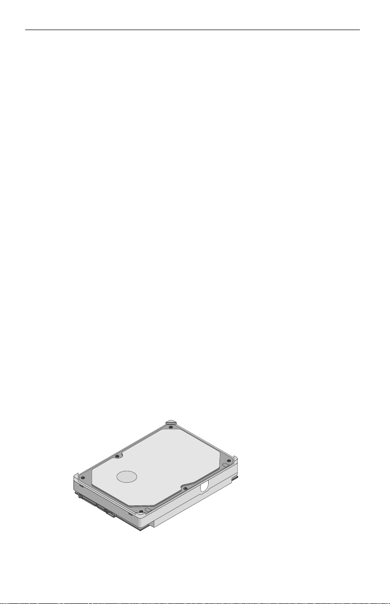
Figure 1. Barracuda Serial ATA V disc drive. . . . . . . . . . . . . . . . . . 2
Figure 2. Typical 5V startup and operation current profile . . . . . . 11
Figure 3. Typical 12V startup and operation current profile . . . . . 11
Figure 4. Serial ATA connectors . . . . . . . . . . . . . . . . . . . . . . . . . . 22
Figure 5. SATA cabling with separate power and|
signal attachments. . . . . . . . . . . . . . . . . . . . . . . . . . . . . 23
Figure 6. SATA cabling with combined power and
signal attachment. . . . . . . . . . . . . . . . . . . . . . . . . . . . . . 23
Figure 7. Mounting dimensions—top, side and end view . . . . . . . 24
Page 10

Page 11

Barracuda Serial ATA V Product Manual, Rev. B 1
1.0 Introduction
This manual describes the functional, mechanical and interface specifications for ST3120023AS, ST 380023AS, and ST360015AS ser ial ATA interface drives.
1.1 About the serial ATA interface
The serial ATA interface provides several advantages over the traditional
(parallel) ATA interface. The primary advantages include:
• Easy installation and configuration with true plug-and-pl ay connectivity. It
is not necessary to set any jumpers or other configuration options.
• Thinner and more flexible cabling for improved enclosure airflow and ease
of installation.
• Scalability to higher performance levels.
In addition, ser ial ATA makes the transition from parallel ATA easy by providing legacy software support. Serial A TA was designed to allow you to install a
serial ATA host adap ter and s erial ATA disc drive in your current system an d
expect all of your existing applications to work as normal.
The serial ATA interface connects each disc drive in a point-to-poin t configuration with the serial ATA host adapter. There is no master/slave relationship
with serial ATA devices like there is with parallel ATA. If two drives are
attached on one serial ATA host adapter, the host operating system views the
two devices as if they were both “masters” on two separate ports. This
essentially means both drives behave as if they are Device 0 (master)
devices.
Note. The host adapter may, optionally, emulate a master/slave environ-
ment to host software where two devices on separate serial ATA
ports ar e represented to host so ftware as a Device 0 (master) and
Device 1 (slave) accessed at the sa me set of host bus ad dres ses. A
host adapter that emulates a master/slave environment manages
two sets of shadow registers. This is not a ty pi ca l s erial ATA environment.
The serial A TA host adapter and drive share the function of emulating parallel
ATA device behavior to provide backward compatibility with existing host systems and software. The Command and Control Block registers, PIO and
DMA data transfers, resets, and interrupts are all emulated.
The serial ATA host adapt er contains a set of registe rs that sh adow the contents of the traditiona l device registers, referred to as the Shadow Regist er
Block. All serial ATA devices behave like Device 0 devices. For additional
Page 12
2 Barracuda Serial ATA V Product Manual, Rev. B
information about how ser ial ATA emulates p arallel ATA, refer to the “Ser ial
ATA: High Speed Serialized AT Attachment” specification. The specification
can be downloaded from http://www.serialata.com.
1.2 Key features
These drives provide the following key features:
• 7,200 RPM spindle speed and 8 M byte buffer combine for superior d esktop performance.
• High instantaneous (burst) data-transfer rates ( up to 150 M bytes per second).
• Giant magnetoresis tive ( GMR) recording heads and EPRML tec hnology,
which provide the drives with increased areal density.
• State-of-the-art cache and on-the-fly error-correction algorithms.
• Full-track multiple-sector tran sfer capability with out local processor intervention.
• Quiet operation.
• 350 Gs nonoperating shock.
• The innovative, shock-absorbing SeaShield
®
cover protects the drive
against electrosta tic discharge (ESD ) and other handlin g damage. It also
includes installation instructions and jumper settings.
• SeaTools diagnostic software performs a drive self-test that eliminates
unnecessar y drive returns.
• The 3D Defense System™, which includes Drive Defense, Data Defense
and Diagnostic Defense, offers the industr y’s most comprehensi ve protection for disc drives.
• Support for S.M.A.R.T. drive monitoring and reporting.
• Support for Read Multiple and Write Multiple commands.
Figure 1. Barracuda Serial ATA V disc drive
Page 13
Barracuda Serial ATA V Product Manual, Rev. B 3
2.0 Drive specifications
Unless otherwise noted, all specific ations are me asured un der ambient c onditions, at 25°C, and nominal power. For convenience, the phrases the drive
and this drive are used throughout this manual to indicate the ST3120023AS,
ST380023AS and ST360 015 AS models.
2.1 Specification summary table
The specifications listed in this table are for quick reference. For details on
specification meas urement or definition, see the appr opriate section of this
manual.
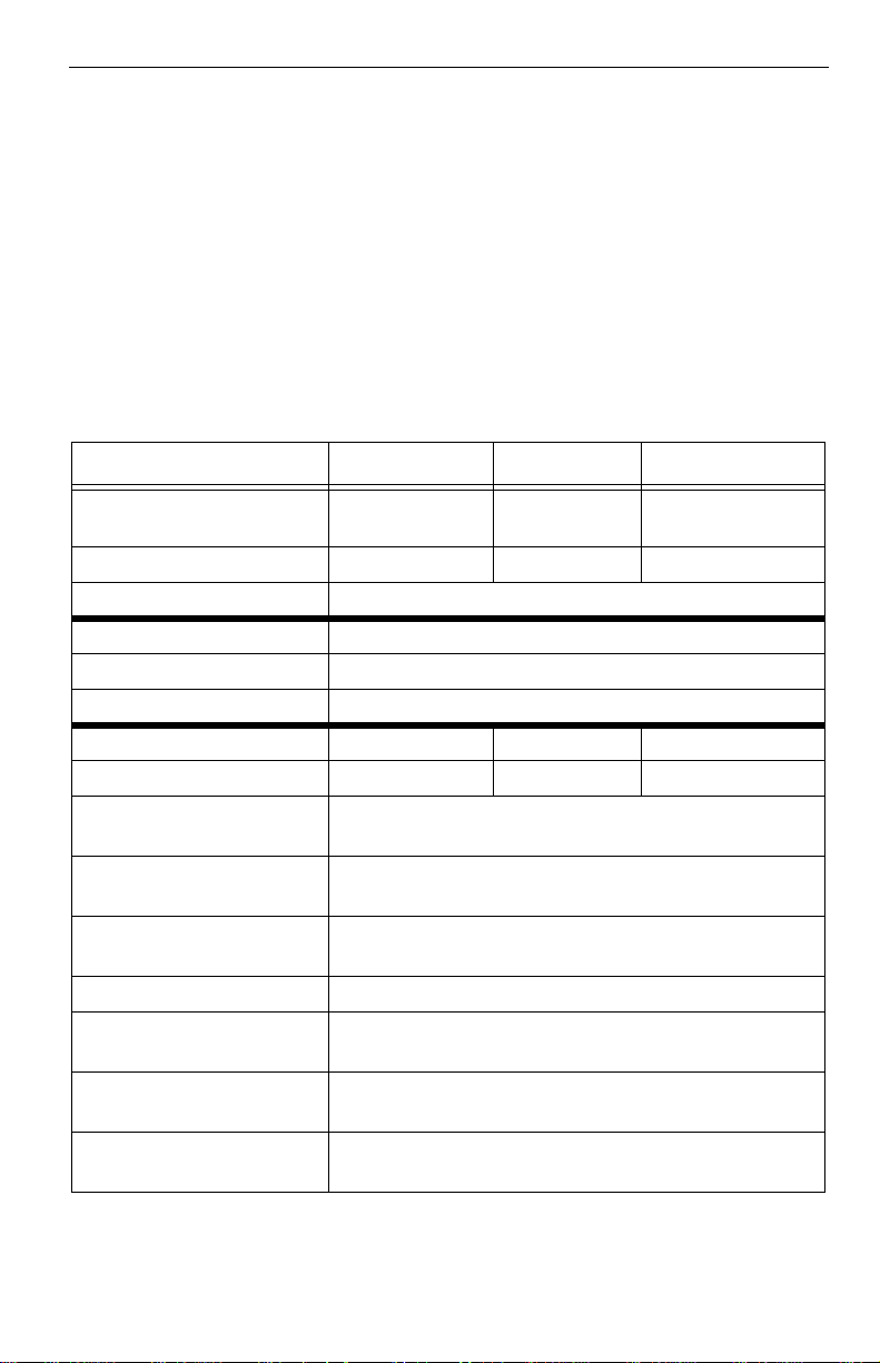
Table 1: Drive specifications
Drive specification ST3120023AS ST380023AS ST360015AS
Formatted Gbytes
(512 bytes/sector)
Guaranteed secto rs 234,441,648 156,301,488 117,231,408
Bytes per sector 512
Default sectors per track 63
Default read/write heads 16
Default cylinders 16,383
Physical read/write heads 4 3 2
Discs 2 2 1
Recording density in BPI
(bits/inch max)
Track density TPI
(tracks/inch max)
Areal density
(Mbits/inch
Spindle speed (RPM) 7,200
Max. Internal transf er rate
(Mbits/sec max)
Sustained transfer rate
(Mbytes/sec)
I/O data transfer rate
(Mbytes/sec max)
2
max)
120 80 60
542,000
78,000
42,200
570
27 to 44
150
Page 14
4 Barracuda Serial ATA V Product Manual, Rev. B
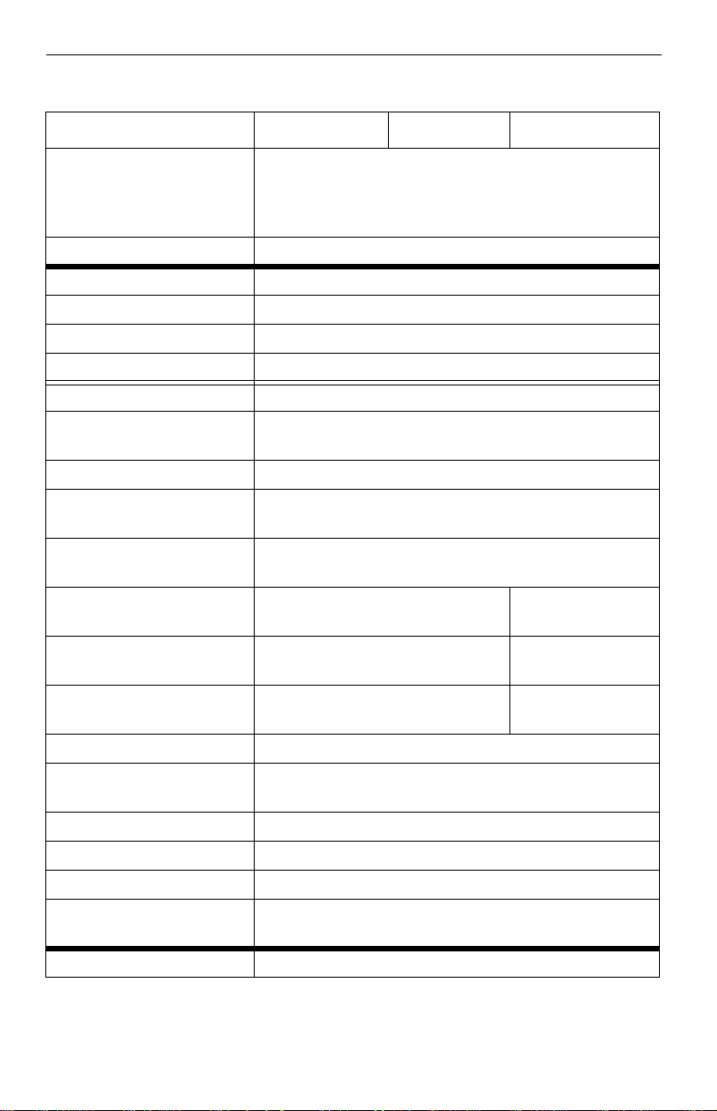
Table 1: Drive specifications
Drive specification ST3120023AS ST380023AS ST360015AS
ATA data-transfer modes
supported
Multiword DMA modes 0–2
Cache buffer 8 Mbytes
Height (mm ma x) 26.1
Width (mm max) 101.85
Length (mm max) 147.0
Weight (typical) 635 grams (1.4 lb)
Average latency (msec) 4.16
Po w e r-on to ready
(typical)
Standby to ready (typical) 10 sec
Startup current (typical)
12V (peak)
Track-to-track seek time
(msec typical)
Average seek time
( typical)
Average seek, read
(typical)
Average seek, write
(typical)
Seek power (typical) 13.5 watts
Operating power
(typical)
Idle mode (typical) 9.5 watts
Standby mode 1.8 watts
Sleep mode 1.8 watts
Voltage tolerance
(including noise)
Ambient temperature 0° to 60°C (op.), –40° to 70°C (nonop.)
9.4 msec 9.0 msec
9.4 msec
10.5 msec
SATA 1.0
PIO modes 0–4
Ultra DMA modes 0–5
10 sec
2.8 amps
1.0 (read), 1.2 (write)
9.0 msec
10.0 msec
13 watts
5V ± 5%
12V ± 10%
Page 15
Barracuda Serial ATA V Product Manual, Rev. B 5
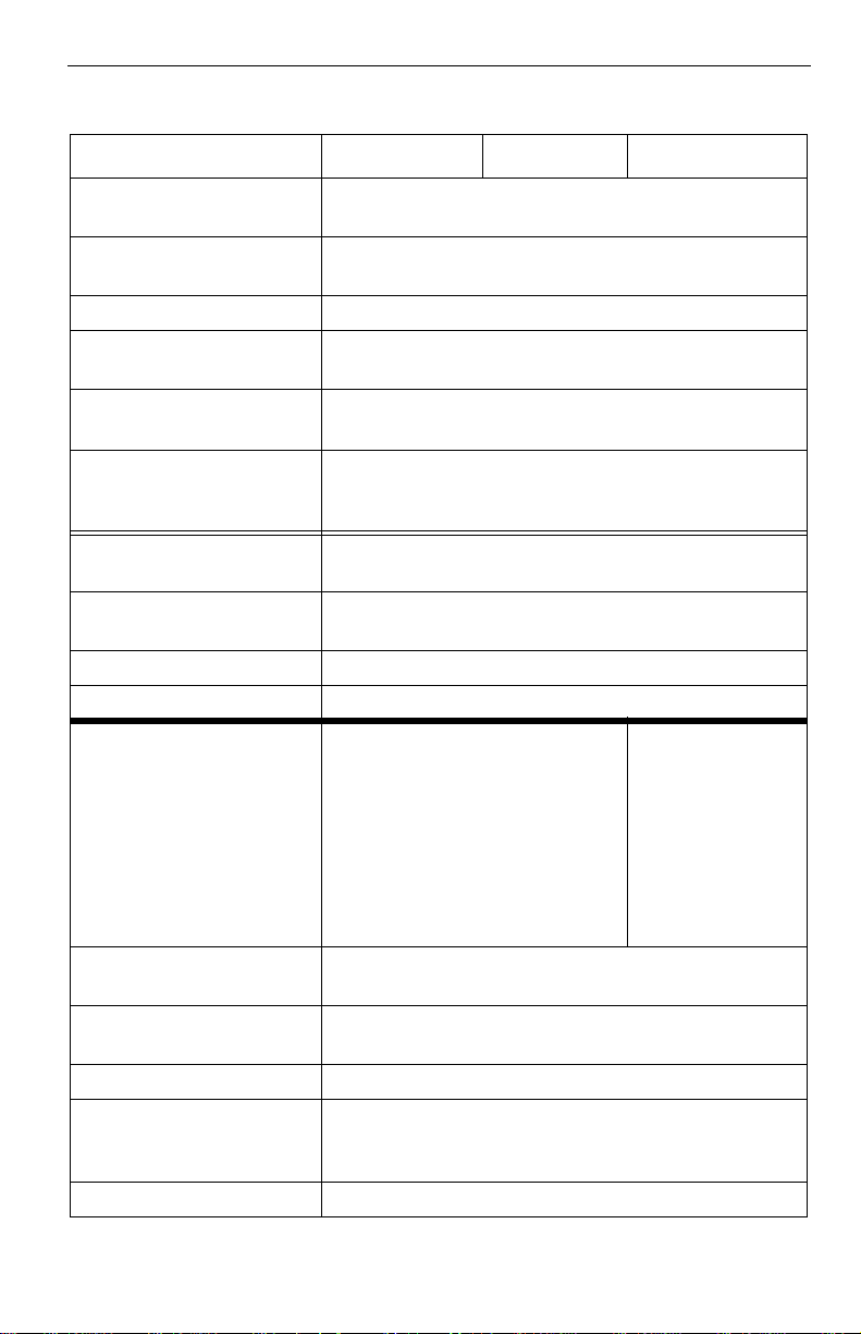
Table 1: Drive specifications
Drive specification ST3120023AS ST380023AS ST360015AS
Temperature gradient
(°C per hour max)
Relative humidity
(op. and nonop.)
Relative humidity gradient 30% per hour max
Wet bulb temperature
(°C max)
Altitude, operating –198.12 m to 3,048 m
Altitude, nonoperating
(meters below mean sea
level, max)
Shock, operatin g
(Gs max at 2 msec)
Shock, nonoperating
(Gs max at 2 msec)
Vibration, operating 0.5 Gs (0 to peak, 22–350 Hz)
Vibration, nonoperating 5 Gs (0 to peak, 22–350 Hz)
Drive acoustics
Sound power (bels)
Idle*
Quiet seek
Performance seek
Nonrecoverable read
errors
Mean time between failures (power-on hours)
Service life 5 Years
Contact start-stop cycles
(25°C, 40% relativ e
humidity)
SeaShield Yes
2.8 (typical)
3.0 (max)
2.8 (typical)
3.0 (max)
3.3 (typical)
3.6 (max)
20°C (op.)
30°C (nonop.)
5% to 90% (op.)
5% to 95% (nonop.)
30 (op.), 40 (nonop.)
(–650 ft to 10,000
–198.12 m to 12,192 m
(–650 ft to 40,000
63
350 Gs
1 per 10
14
600,000
50,000
+ ft)
+ ft)
2.1 (typ)
<2.5 (max)
2.4 (typ)
2.8 (max)
3.0 (typical)
3.4 (max)
bits read
Page 16
6 Barracuda Serial ATA V Product Manual, Rev. B
*During periods of drive idle, some offline activity may occur according to the S.M.A.R.T.
specification, which may increase acoustic and power to operational levels.
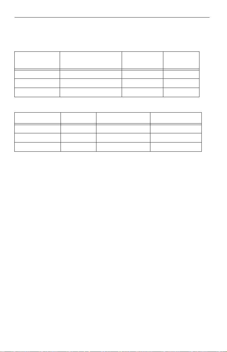
2.2 Formatted capacity
Drive model Formatted Gbytes
ST3120023AS 120 234,441,648 512
ST380023AS 80 156,301,488 512
ST360015AS 60 117,231,408 512
Guaranteed
sectors
Bytes per
sector
2.3 Default logical geometry
Cylinders Read/write heads Sectors per track
ST3120023AS 16,383 16 63
ST380023AS 16,383 16 63
ST360015AS 16,383 16 63
LBA mode
When addressing these drives in LBA mode, all blocks (sectors) are c on secutively numbered from 0 to n–1, where n is the number of guaranteed sectors
as defined above.
Page 17
Barracuda Serial ATA V Product Manual, Rev. B 7
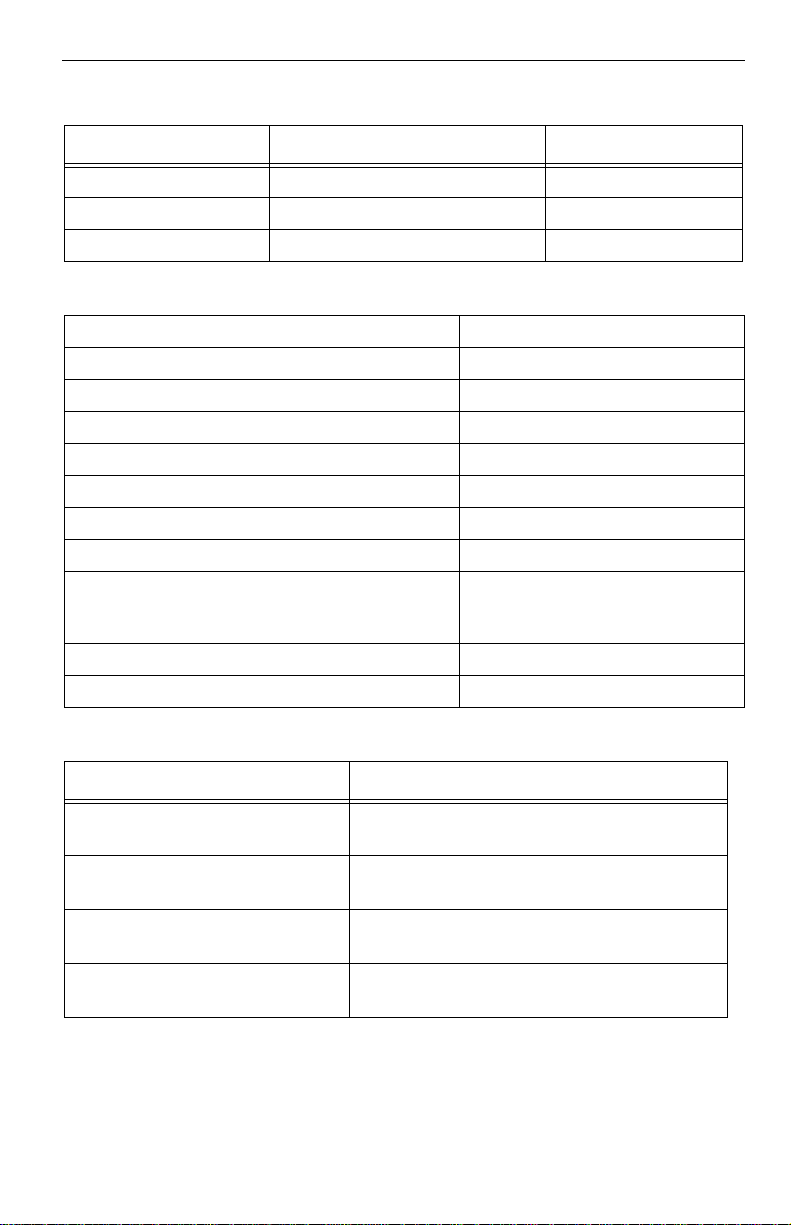
2.4 Physical organization
Drive model Read/write heads Number of discs
ST3120023AS 4 2
ST380023AS 3 2
ST360015AS 2 1
2.5 Recording and interface technology
Interface Serial ATA (SATA)
Recording method 16/17 EPRML
Recording density BPI (bits/inch max) 542,000
Track density TPI (tracks/inch max) 78,000
Areal density (Mbits/inch
Spindle speed (RPM) (± 0.2%) 7,200
Maximum Internal transfer rate (Mbits/sec) 570
Sustained transfer rate (Mbytes/sec) 27 to 44
I/O data-transfer rate (Mbytes/sec max) 16.6 (PIO mode 4)
Interleave 1:1
Cache buffer 8 Mbytes
2
max) 42,200
100 (Ultra DMA mode 5)
150 (SATA 1.0)
2.6 Physical characteristics
Drive specification
Maximum height(mm)
(inches)
Maximum width(mm)
(inches)
Maximum length(mm)
(inches)
Typical weight(grams)
(pounds)
26.1
1.028
101.85
4.01
147.0
5.787
635
1.40
Page 18
8 Barracuda Serial ATA V Product Manual, Rev. B
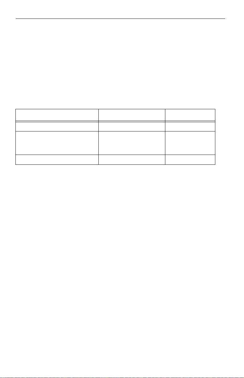
2.7 Seek time
Seek measurements ar e taken w ith nom inal power at 25°C a mbient temper ature. All times are mea sured using drive diagnos tics. The specifications i n
the table below are defined as follows:
• Track-to-track seek time is an average of all possible single-track seeks in
both directions.
• Average seek time is a true statistical rand om averag e of at least 5,000
measurements of seeks between random tracks, less overhead.
Table 2: Typical seek times
Typical seek times (msec) Read Write
Track-to-track 1.0 1.2
Average
1 disc
2 disc
Average latency: 4.16 4.16
9.4
9.0
10.5
10.0
Note. These dri ves are designed to c onsistently meet the seek times repre-
sented in this manual. Physical seeks, regardless of mode (such as trackto-track and average), are expected to meet the noted values. However,
due to the manner in which these drives are formatted, benchmark tests
that include command overhead or measure logical seeks may produce
results that vary from these specifications.
2.8 Start/stop times
Power-on to Ready (sec) 10 (max)
Standby to Ready (sec) 10 (max)
Ready to spindle stop (sec) 10 (max)
2.9 Power specifications
The drive receives DC power (+5V or +12V) through a native SATA power
connector. See Figures 5 and 6 on page 23.
Page 19

Barracuda Serial ATA V Product Manual, Rev. B 9
2.9.1 Power consumption
Power requirements for the drives are listed in the table on page 9. Typical
power measurements are based on an average of drives tested, under nominal conditions, using 5.0V and 12.0V input voltage at 25°C ambient temperature.
• Spinup power
Spinup power is measured fro m the time of power-on to the ti me t hat th e
drive spindle reaches operating speed .
• Seek mode
During seek mode, the read/wr ite actuator arm moves toward a specific
position on the d isc surface and do es not execute a read or write op eration. Servo electronics are active. Seek mode power represents the worstcase power consumption, using only random seeks with read or write
latency time. This mode is not typical and is provided for worst-case information.
• Read/write power and current
Read/write power is measu red with the heads on track, based on a 16sector write followed by a 32-msec delay, then a 16-sector read followed
by a 32-msec delay.
• Operating power and current
Operating power is measured using 40 percent random seeks, 40 percent
read/write mode (1 write for each 10 reads) and 20 percent drive idle
mode.
• Idle mode power
Idle mode power is measur ed wi th the d r ive up to sp eed , wi th s ervo electronics active and with the heads in a random track location.
• Standby mode
During Standby mode, the d rive accepts comma nds, but the drive is not
spinning, and the servo and read/write electronics are in power-down
mode.
Page 20

10 Barracuda Serial ATA V Product Manual, Rev. B
Table 3: DC power requirements
Power dissipation
(watts, ST3120023AS)
Average
(watts, 25° C)
5V typ
amps
12V typ
amps
Spinup — — 2.8 (peak)
Idle 7.5 0.74 0.32
Idle* (with offline activity) 9.5 0.74 0.48
Operating 40% r/w.
40% seek, 20% inop. 13 0.74 0.79
Seeking 13.5 0.73 0.82
Standby 1.8 0.34 0.01
Sleep 1.8 0.34 0.01
*During periods of drive idle, some offline activity may occur according to the S.M.A.R.T.
specification, which may increase acoustic and power to operational levels.
Page 21

Barracuda Serial ATA V Product Manual, Rev. B 11
2.9.1.1 Typical current profile
1.2
1.0
0.8
Amps
0.6
0.4
+5 Volt Current during spindle start — Typical Amperes
0.2
0.0
0.0 2 4 6 8 10 12 14 16
Seconds
Figure 2. Typical5V startup and operation current profile
+12 Volt Current during spindle start — Typical Amperes
2.55
2.125
1.70
Amps
1.275
0.85
0.425
0.0
0.02 4 6 8 10121416
Seconds
Figure 3. Typical12V startup and operation current profile
18
18
Page 22

12 Barracuda Serial ATA V Product Manual, Rev. B
2.9.2 Deferred spinup
Barracuda Seria l ATA V drives provide a deferred spinup feature which storage subsystem contr ollers c an use to sequence disc dr ive initial ization. Th is
is beneficial to s ystems which include multiple Ser ial ATA hard dis c drives
because it allows s ubsystem contr ollers to stag ger the spinup of each dr ive
to accommodate available power supply current. This feature does not
impact time-to-ready in typical desktop systems.
To accommoda te the d eferred spinup of mul tiple disc dri ves in an en closur e,
Barracuda Seri al ATA V disc drives will spin up only afte r power is appli ed to
the drive and after successful PHY (Physical layer) initialization. PHY initialization occurs after the PH Y enters the DP7:DR_Ready sta te. This state is
reached after a successful exchange of Out-Of- Band (OOB) signals with a
functional host-sid e Serial ATA port. In desktop systems, SATA transceivers
should initialize OOB as soon as power comes ready to gua rantee the dr ive
spins up quickly. Seagate disc drives will not spin up witho ut an operational
host-side Serial ATA transceiver.
Additional d etails
Upon system power up, PHY communicati on is in itiated with a COMRESET
signal, which is generated by the host-side transceiver. COMRESET is followed by a COMINIT signal generated by the disc drive transceiver. COMRESET and COMINIT are followed by an exchange of COMWAKE signals and
Align prim itives. The disc d rive will sp in up after the succ essful exchang e of
Align primitives cause the PHY to come ready.
For more details, refer to:
• Section 6.8 of the Serial ATA 1.0 High-Speed Serialized AT Attachment
specification
• Section 6.2 of the Serial ATA II: Extensions to Serial ATA 1.0 specification
• SATA 1.0 design guides
Note. These sp ecifica tions and guides are available on the Serial ATA web
site (www.serialata.org).
2.9.3 Conducted noise
Input noise ri pple is measured at the host system power supply acros s an
equivalent 80-ohm resistive load on the +12 volt line or an equivalent 15-ohm
resistive load on the +5 volt line.
• Using 12-volt power, the drive is expected to operate with a maximum of
120 mV peak-to-peak square-wave injected noise at up to 10 MHz.
Page 23

Barracuda Serial ATA V Product Manual, Rev. B 13
• Using 5-volt power, the drive is expected to op erate with a maximum of
100 mV peak-to-peak square-wave injected noise at up to 10 MHz.
Note. Equivalent resis tance is cal culate d by dividin g th e nomi nal vol tage by
the typical RMS read/write current.
2.9.4 Voltage tolerance
Voltage tolerance (including noise):
5V ± 5%
12V ± 10%
2.9.5 Power-management modes
The drive provides programmable power management to provide greater
energy efficiency. In most systems, you can control power management
through the syst em setup program. The drive features the following powermanagement modes:
Power modes Heads Spindle Buffer
Active Tracking Rotating Enabled
Idle Tracking Rotating Enabled
Standby Parked Stopped Enabled
Sleep Parked Stopped Disabled
• Active mode
The drive is in Active mode during the read/write and seek operations.
• Idle mode
The buffer remains enabled, and the drive accepts all commands and
returns to Active mode any time disc access is necessary.
• Standby mode
The drive enters Stand by mode when the host send s a Stand by Immediate command. If the host has set the standby t imer, th e drive can also
enter Standby mode automati cally after the drive has been inacti ve for a
specifiable length of time. The standby timer del ay is established using a
Standby or Idle command. In Standby mode, the drive buffer is enabled,
the heads are parked and the spindle is at rest. The drive accepts all commands and returns to Active mode any time disc access is necessary.
Page 24

14 Barracuda Serial ATA V Product Manual, Rev. B
• Sleep mode
The drive enters Sleep mode afte r receiving a Sleep comman d from the
host. In Sleep mode, the drive buffer is disabled, the heads are par ke d
and the spindle i s a t r e st. Th e d rive leaves Sleep mode after i t r ec eives a
Hard Reset or Soft Reset f rom the ho st. After r eceiving a reset, the d rive
exits Sleep mode and enters Standby mode with all current translation
parameters intact.
• Idle and Standby timers
Each time the drive performs an Active function (rea d, write or seek), the
standby timer is rein itialized an d begins coun ting down from its specifie d
delay times to zero. If the standby timer reaches zero before any drive
activity is required , the dr ive makes a transi tion to S tandby mode. In bot h
Idle and Standby mode, the drive accepts a ll commands and returns to
Active mode when disc access is necessary.
2.10 Environmental specifications
2.10.1 Ambient temperature
Ambient temperature is defined as the temperature of the environment
immediately surrou nding the drive. Actual dr ive case te mperature s hould no t
exceed
mended measurement locations are shown in Figure 3 on page 23.
69°C (156°F) within the operating ambient conditions. Recom-
Above 1,000 feet (305 meters), the maximum tempera tur e is d erate d li nea r ly
to 112°F (44°C) at 10,000 feet (3,048 meters).
Operating 0° to 60°C (32° to 140°F)
Nonoperating –40° to 70°C (–40° to 158°F)
Page 25

Barracuda Serial ATA V Product Manual, Rev. B 15
2.10.2 Temperature gradient
Operating 20°C per hour (68°F per hour max),
without condensation
Nonoperating 30°C per hour (86°F per hour max)
2.10.3 Humidity
2.10.3.1 Relative humidity
Operating 5% to 90% noncondensing (30% per hour max)
Nonoperating 5% to 95% noncondensing (30% per hour max)
2.10.3.2 Wet bulb temperature
Operating 30°C (86°F max)
Nonoperating 40.0°C (104°F max)
2.10.4 Altitude
Operating –198.12 m to 3,048 m (–650 ft to 10,000+ ft)
Nonoperating –198.12 m to 12,192 m (–650 ft to 40,000+ ft)
2.10.5 Shock
All shock specifications assume that the drive is mounted securely with the
input shock applied at the dr ive mounting screws. Shock may be applied in
the X, Y or Z axis.
2.10.5.1 Operating shock
These drives comply with the performa nce levels specified in this documen t
when subjected to a ma ximum operating sho ck of 63 Gs based on ha lf-sine
shock pulses of 2 msec. Shocks should not be repeated more than two times
per second.
2.10.5.2 Nonoperating shock
The nonoperating shock level that the drive can experi ence without i ncurr in g
physical damage or degradation in performance when subse quently put into
operation is 350 Gs based on a nonrepetitive half-sine shock pulse of 2 msec
duration.
Page 26

16 Barracuda Serial ATA V Product Manual, Rev. B
2.10.6 Vibration
All vibration specifications assume that the drive is mounted securely with the
input vibration applied at the drive mounting screws. Vibration may be
applied in the X, Y or Z axis.
2.10.6.1 Operating vibration
The maximum vibration l evel s that the drive may experience while mee ting
the performance standards specified in this document are specified below.
5–22 Hz 0.25-inch displacement (zero to peak)
22–350 Hz 0.5 Gs acceleration (zero to peak)
2.10.6.2 Nonoperating vibration
The maximum nonoperating vibration levels that the drive may experience
without incurrin g physical damage or de gradation in perform ance when subsequently put into operation are specified below.
5–22 Hz 1.0-inch displacement (zero to peak)
22–350 Hz 5.0 Gs acceleration (zero to peak)
2.11 Drive acoustics
Drive acoustics are meas ured as overall A-weighted acoustic sound power
levels (no pure tones). All meas urements ar e consistent with ISO do cument
7779. Sound power measurements are taken under essentially free-field
conditions over a reflecting pl ane. For all tests, the drive is or iented with th e
cover facing upward.
For seek mode tests, the drive is placed in seek mode only. The number of
seeks per second is defined by the following equation:
(Number of seeks per second = 0.4 / (average latency + average access time)
Table 4: Fluid Dynamic Bearing (FDB) motor acoustics
Acoustic mode
Models Idle* Quiet seek Performance seek
ST3120023AS
ST380023AS
ST360015AS 2.1 bels (typ)
2.8 bels (typ)
3.0 bels (max)
<2.5 bels (max)
2.8 bels (typ)
3.0 bels (max)
2.4 bels (typ)
2.8 bels (max)
3.3 bels (typ)
3.6 bels (max)
3.0 bels (typ)
3.4 bels (max)
Page 27

Barracuda Serial ATA V Product Manual, Rev. B 17
Note. Duri ng periods of drive idle, some offline activity may occur accord-
ing to the S.M.A.R.T. specification, which may increa se ac ou sti c and
power to operational levels.
2.12 Electromagnetic immunity
When properly installed in a representative host sys tem, the drive operates
without errors or degradation in performance when subjected to the radio frequency (RF) environments defined in the following table:
Table 5: Radio frequency environments
Test Description
Electrostatic discharge Contact, HCP, VCP: ± 4
Radiated RF immunity 80 to 1,000 MHz, 3 V/m,
Electrical fast transient ± 1 kV on AC mains, ± 0.5
Surge immunity ± 1 kV differential, ± 2 kV
Conducted RF immunity
Voltage dips, interrupts
kV; Air: ± 8 kV
80% AM with 1 kHz sine
900 MHz, 3 V/m, 50%
pulse modulation @ 200
Hz
kV on external I/O
common, AC mains
150 kHz to 80 MHz, 3
Vrms, 80% AM with 1 kHz
sine
0% open, 5 seconds
0% short, 5 seconds
40%, 0.10 seconds
70%, 0.01 seconds
Performance
level
B EN 61000-4-2: 95
A EN 61000-4-3: 96
B EN 61000-4-4: 95
B EN 61000-4- 5: 95
A EN 61000-4- 6: 97
C
C
C
B
Reference
standard
ENV 50204: 95
EN 61000-4-11: 94
Page 28

18 Barracuda Serial ATA V Product Manual, Rev. B
2.13 Reliability
Nonrecoverable read errors 1 per 1014 bits read, max
Mean time between failures (MTBF) 600,000 power-on hours
(nominal power, 25°C am bient temperature )
Contact start-stop cycles 50,000 cycles
Preventive maintenance None required
(at nominal voltage and te mperature, with 60
cycles per hour and a 50% duty cycle)
2.14 Agency certification
2.14.1 Safety certification
The drives are recognized in accordance with UL 1950 and CSA C22.2 (950)
and meet all applicable sect ions of IEC950 and EN 60950 as tested by TUV
North America.
2.14.2 Electromagnetic compatibility
Hard drives that display the CE m ark comp ly with the Europ ean Union (EU)
requirements specified in the Electromagnetic Compatibility Directive (89/
336/EEC). Te sting is performed to th e levels specified by the product standards for Information Technology Equipment (ITE). Emission levels are
defined by EN 55022, Class B and the immunity levels are defined by EN
55024.
Seagate uses an indepen dent laborator y to confir m compliance with the EC
directives specified in t he pr evious paragraph. Dr i ves are test ed in r e pres entative end-user systems. Although CE-marked Seagate drives comply with
the directives when used in the test sy stems, we cannot guarantee that all
systems will comply with the directives. The drive is designed for operation
inside a properly designed enclosure, with properly shielded I/O cable (if necessary) and ter minators on all unused I/O ports. Computer manufacturers
and system integrators should confirm EMC compliance and provide CE
marking for their products.
Korean RRL
If these drives have the Korea Ministry of Information and Communication
(MIC) logo, they comply with paragraph 1 of Article 11 of the Electromagnetic
Compatibility control Re gulation a nd meet the E lectromagn etic Compa tibility
(EMC) Framework requirements of the Radio Research Laboratory (RRL)
Ministry of Information and Communication Republic of Korea.
Page 29

Barracuda Serial ATA V Product Manual, Rev. B 19
These drives have been tested and comply with the Electromagnetic Interference/Electromagneti c Susceptib ility (EMI/EMS ) for Class B produc ts. Drives
are tested in a representative, end-user system by a Korean-recognized lab.
• EUT name (model numbers):
ST3120023AS
ST380023AS
ST360015AS
• Certificate numbers:
ST3120023AS E-H011-02-4134 (B)
ST380023AS E-H011-02-4 133 (B)
ST360015AS E-H011-02-4 135 (B)
• Trade name or applicant: Seagate Technology
• Manufacturing date: Pending
• Manufacturer/nationality: Singapore
Australian C-Tick (N176)
If these models have the C-Tick marking, they comply with the Australia/New
Zealand Standard AS/NZS354 8 1995 and meet the Electromagnetic Compatibility (EMC) Framework requirements of the Australian Communication
Authority (ACA).
2.14.3 FCC verification
These drives are intended to be contained so lel y with in a pe r son al co mpu ter
or similar enclosure (not attached as an external device). As such, each drive
is considered to be a subassembly even when it is individually marketed t o
the customer. As a subassembly, no Federal Communications Commission
verification or certification of the device is required.
Seagate Techn ology LLC has tested this device in e nclosures as descr ibed
above to ensure that the total assembly (enclosure, disc dr ive, motherboard,
power supply, etc.) does comply with the limits for a Class B computing
device, pursuant to Subpar t J, Part 15 of th e FCC r ules. Opera tion wi th noncertif ied assemblies is likely to resu lt in interference to radio and television
reception.
Radio and television interference. This equipment generates and uses
radio frequency energy and if not installed and used in strict accordance with
the manufacturer’s instructions, may cause interference to radio an d television reception.
This equipment is designed to provide reasonable protection against such
interference in a residential in stallation. However, there is no guarantee that
Page 30

20 Barracuda Serial ATA V Product Manual, Rev. B
interference will not occur in a par ticular instal lation. If this equipment does
cause interference to radio or television , whi ch can be d etermined by turn in g
the equipment on and off, you are enco uraged to tr y one or more o f the following corrective measures:
• Reorient the receiving antenna.
• Move the device to one side or the other of the radio or TV.
• Move the device farther away from the radio or TV.
• Plug th e computer into a different ou tlet so that the receiver and co mputer
are on different branch outlets.
If necessary, you should consult your dealer or an experienced radio/te levision technician for additiona l suggestion s. You may find helpful th e following
booklet prepared by the Federal Communications Commission: How to Iden-
tify and Resolve Radio-Television Interference Problems. This booklet is
available from the Superintendent of Docume nts, U.S. Government Printin g
Office, Washington, DC 20402. Refer to publication number 004-000-00345-
4.
Page 31

Barracuda Serial ATA V Product Manual, Rev. B 21
3.0 Configuring and mounting the drive
This section conta ins the specificatio ns and instructions for configuring and
mounting the drive.
3.1 Handling and static-discharge precautions
After unpacking, and before installation, the drive may be exposed to potential handling and ele ctrostatic disc harge (ESD ) hazards. Obser ve the following standard handling and static-discharge precautions:
Caution:
• The SeaShell™ replaces electrostatic discharge (ESD) bags. The SeaShell
package is a shock-ribbed, transparent clamshell enclosure that limits a
drive’s exposure to ESD and also protects against external shocks and
stresses. The desig n permits attac hing cable s, software loading and la bel/
barcode scanning without removing the drive from the SeaShell. This
minimizes handling da mage. Keep the dr ive in the SeaSh ell package until
you are ready for installation.
• The drive has a cover called SeaShield
cover—it protec ts the drive from electrosta tic discharge (ESD) and mi nor
impact damage. The SeaShield cover also includes installation instructions
and jumper settings. Removing the SeaShield voids the warranty.
• Before handling the drive, put on a grounded wrist strap, or ground yourself
frequently by touching the metal chassis of a com puter that is plugged int o
a grounded outlet. Wear a grounded wrist strap throughout the entire
installation procedure.
• Handle the drive by its edges or frame only.
• The drive is extremely fragile—handle it with care. Do not press down on the
drive top cover.
• Always rest the drive on a padded, antistatic surface until you mount it in the
computer.
• Do not touch the connector pins or the printed circuit board.
• Do not remove the factory-installed labels from the drive or cover them with
additional labels. Removal voids the warranty. Some factory-installed labels
contain information n eeded to service the drive. Ot her labels are used to
seal out dirt and contamination.
. Do not remove this permanent
Page 32

22 Barracuda Serial ATA V Product Manual, Rev. B
3.2 Configuring the drive
Each drive on the ser ial ATA interface connects in a point-to-po int conf iguration with the ser ial ATA ho st adapter. There is no master/slave relationshi p
because each drive is considered a master in a point-to-point relationships. If
two drives are attached on one serial ATA host adapter, the host operating
system views the two devices as if they were both “masters” on two separate
ports. This means both drives behave as if they are Device 0 (master)
devices.
Serial ATA drives are designed for easy installation with no jumpers, terminators, or other settings. It is no t ne cess ar y to set any ju mpers on thi s dr ive for
proper operation. The jumper block adjacent to the signal connector is for
factory use only.
SATA Signal
Jumper Block
(factory use only)
Figure 4. Serial ATA connectors
SATA Power
3.3 Serial ATA cables and connectors
The serial ATA interface cable consists of four conductors in two differential
pairs, plus three ground co nnections. The cable size m ay be 30 to 26 AWG
with a maximum length of one mete r (39. 37 in ch es ). See Table 6 for connector pin definitions. Either end of the SATA signal cable can be attached to the
drive or host.
For direct backplane connection, the dr ive connectors are inserted dir ectly
into the host receptacl e. The drive and the host receptacle in corporate features that enable the dire ct connection to be hot pl uggable and blind mateable.
Page 33

Barracuda Serial ATA V Product Manual, Rev. B 23
For installations which require cables, you can connect the drive using
cabling which separates the power con nector an d the SATA signal connector
as illustrated in Figur e 5, or you can connect the dr ive using cabling which
integrates both cables in one molded connector as illustrated in Figure 6.
Signal connector
Power connector
Signal cable
Power cable
Figure 5. SATA cabling with separate power and signal attachments
Signal connector
Power connector
Signal cable
Power cable
Figure 6. SATA cabling with combined power and signal attachment
Each cable is keyed to ensure correct orientation.
3.4 Drive mounting
You can mount the drive in any orientation using four screws in the sidemounting holes or four screws in the bottom-mounting holes. See Figure 7 on
page 24 for drive mounting dimensions. Follow these important mounting
precautions when mounting the drive:
• Allow a minimum clearance of 0.03 0 inches (0.76 mm) around the entire
perimeter of the drive for cooling.
• Use only 6-32 UNC mounting screws.
• The screws should be inserted no more than 0.200 inch (5.08 mm) into the
bottom mounting holes and no more than 0.14 inch (3.55 mm) into the side
Page 34

24 Barracuda Serial ATA V Product Manual, Rev. B
mounting holes.
• Do not overtighten the mounting screws (maximum torque: 6 inch-lb).
• Do not use a drive interface cable that is more than 18 inches long.
[1]
5.787 (146.9898) max.
[2]
.128
(3.251)
1.122
+ .020
(28.499
+ .508)
[1]
CLof conn. Datum B
2.32
(58.93)
(41.605)
.814
(20.676)
2 x 3.750
(2 x 95.25)
1.638
[1]
4.000
(101.6)
CLof drive
[1]
.250 + .015
(6.35 + .381)
[1]
4.000
(101.6)
1.028 max
(26.111 max)
2 x 1.750
(2 x 44.45)
[1] [2]
Notes:
Dimensions are shown in inches (mm).
[1] Dimensions per SFF-8301 specification
[2] Measured with drive resting on Seashield
(bottom surface of form factor)
[1]
(3x both sides)
[2]
4.000
(101.6)
[1]
Figure 7. Mounting dimensions—top, side and end view
Page 35

Barracuda Serial ATA V Product Manual, Rev. B 25
4.0 Serial ATA (SATA) interface
These drives use the industry-standard Serial AT A interf ace that supports 16bit data transfers. It supports ATA programmed input/output (PIO) modes 0 –
4; multiword DMA modes 0–2, and Ultra DMA mod es 0–5. The drive also
supports the use of the IORDY signal to provide reliable high-speed data
transfers.
For detailed information about the Serial ATA interface, refer to the “Serial
ATA: Hi gh Speed Serialized AT A ttachment” specification. The specification
can be downloaded from http://www.serialata.com..
Page 36

26 Barracuda Serial ATA V Product Manual, Rev. B
4.1 Serial ATA device plug connector pin definitions
Table 6 summarizes th e signals on the Serial A TA interfac e and power c onnectors..
Table 6: Serial ATA connector pin definitions
Segment Pin Function Definition
S1 Ground 2nd mate
S2 A+ Differential signal pair A from Phy
S3 A-
Signal
Power
S4 Ground 2nd mate
S5 B- Differential signal pari B from Phy
S6 B+
S7 Ground 2nd mate
Key and spacing separate signal and power segments
P1 V
P2 V
P3 V
33
33
33
3.3V power
3.3V power
3.3V power, pre-charge, 2nd mate
P4 Ground 1st mate
P5 Ground 2nd mate
P6 Ground 2nd mate
P7 V
P8 V
P9 V
5
5
5
5V power, pre-charge, 2nd mate
5V power
5V power
P10 Ground 2nd mate
P11 Reserved 1. The pin corresponding to P11 in the back-
plane receptacle connector is also
reserved
2. The corresponding pin to be mated with
P11 in the power cable receptacle connector shall always be grounded
P12 Ground 1st mate.
P13 V
P14 V
P15 V
12
12
12
12V power, pre-charge, 2nd mate
12V power
12V power
Page 37

Barracuda Serial ATA V Product Manual, Rev. B 27
Notes:
1. All pins are in a single row, with a 1.27 mm (0.050”) pitch.
2. The comments on the mating sequence apply to the case of ba ckplane
blindmate connector only. In this case, the mating sequences are:
• the ground pins P4 and P12.
• the pre-charge power pints and the other ground pins.
• the signal pins and the rest of the power pins.
3. There are thr ee power pin s for each voltage. One p in from e ach voltage
is used for pre-charge when i nstal led i n a blind-mate backplane confi guration.
4. All used voltage pins (V
) must be terminated.
x
Page 38

28 Barracuda Serial ATA V Product Manual, Rev. B
4.2 Supported ATA commands
The following table lists Serial ATA standard commands that the dr ive supports. For a detailed description of the ATA commands, refer to the Serial
ATA: High Speed Serialized AT Attachment specification. See “S.M.A.R.T.
commands” on page 37.for details and subcommands used in the S.M.A.R.T.
implementation.
Table 7: Supported ATA commands
Command name Command code (in hex)
ATA-standard commands
Device Configuration Restore B1h/C0h
Device Configuration Freeze Lock B1h/C1h
Device Configuration Identify B1h/C2h
Device Configuration Set B1h/C3h
Download Microc od e 92h
Execute Device Diagnostics 90h
Flush Cache E7h
Identify Device ECh
Initialize Device Parameters 91h
Read Buffer E4h
Read DMA C8h
Read DMA without Retries C9h
Read Long with Retries 22h
Read Long without Retries 23h
Read Multiple C4h
Read Native Max Address F8h
Read Sectors 20h
Read Sectors without Retries 21h
Read Verify Sectors 40h
Read Verify Sectors without Retries 41h
Seek 70h
Set Features EFh
Set Max Address F9h
Page 39

Barracuda Serial ATA V Product Manual, Rev. B 29
Table 7: Supported ATA commands
Command name Command code (in hex)
Set Multiple Mode C6h
S.M.A.R.T. Disable Operations B0h/D9h
S.M.A.R.T. Enable/Disab l e A u tos ave B0h/D2h
S.M.A.R.T. Enable Operations B0h/D8h
S.M.A.R.T. Enable/Disable Auto Offline B0h/DBh
S.M.A.R.T. Enable One Attribute Modification B0h/E0h
S.M.A.R.T. Execute Offline B0h/D4h
S.M.A.R.T. Read Attribute Thresholds B0h/D1h
S.M.A.R.T. Read Data B0h/D0h
S.M.A.R.T. Read Log Sector B0h/D5h
S.M.A.R.T. Return Status B0h/DAh
S.M.A.R.T. Save Attribut e Values B0 h/D3h
S.M.A.R.T. Write Attribute Thresholds B0h/D7h
S.M.A.R.T. Write Attribute Values B0h/E1h
S.M.A.R.T. Write Log Sector B0h/D6h
Write Buffer E8h
Write DMA CAh
Write DMA without Retries CBh
Write Long with Retries 32h
Write Long without Retries 33h
Write Multiple C5h
Write Sectors 30h
,
31h
Page 40

30 Barracuda Serial ATA V Product Manual, Rev. B
Table 7: Supported ATA commands
Command name Command code (in hex)
ATA-standard power-management commands
Check Power Mode 98h or E5h
Idle 97h or E3h
Idle Immediate 95h or E1h
Sleep 99h or E6h
Standby 96h or E2h
Standby Immediate 94h or E0h
ATA-standard security commands
Security Set Password F1h
Security Unlock F2h
Security Erase Prepare F3h
Security Erase Unit F4h
Security Freeze Lock F5h
Security Disable Password F6h
4.2.1 Identify Device command
The Identify Device command (command code EC
) transfers information
H
about the drive to the host following power up. The data is organized as a single 512-byte block of data, whose contents are shown in the table on page
27. All reserved bits or words should be set to zero. Par ameters listed with an
“x” are drive-specific o r vary with the state of the dr ive. See Section 2.0 on
page 3 for default parameter settings.
The following commands contain drive-specific features that may not be
included in the Serial ATA specification.
Page 41

Barracuda Serial ATA V Product Manual, Rev. B 31
Table 8: Drive-specific commands
Word Description Value
Configuration information:
• Bit 15: 0 = ATA; 1 = ATAPI
0
1 Number of logical cylinders 16,383
2 ATA-reserved 0000
3 Number of logical heads 16
4 Retired 0000
5 Retired 0000
6 Number of logical sectors per logical track: 63003F
• Bit 7: removable media
• Bit 6: remova ble controller
• Bit 0: reserved
0C5A
H
H
H
H
H
7–9 Retired 0000
10–19 Serial number: (20 ASCII characters, 0000H
ASCII
= none)
20 Retired 0000
21 Retired 0400
22 Obsolete 0000
23–26 Firmware revisi on (8 ASCII ch aracter string,
x.xx
padded with blanks to end of string)
27–46 Drive model number: (40 ASCII characters ,
padded with blanks to end of string)
ST3120023AS
ST380023AS
ST360015AS
47 (Bits 7–0) Maximum sector s per inter rupt on
Read multiple and Write multiple (16) 8010
48 Reserved 0000
49 Standard Standby timer, IORDY supported
2F00
and may be disabled
50 ATA-reserved 0000
51 PIO data-transfer cycle timing mode 0200
52 Retired 0200
53 Words 54–58, 64–70 and 88 are valid 0007
54 Number of current logical cylinders xxxx
H
H
H
H
H
H
H
H
H
H
H
H
Page 42

32 Barracuda Serial ATA V Product Manual, Rev. B
Table 8: Drive-specific commands
Word Description Value
55 Number of current logical heads xxxx
56 Number of current logic al se cto rs per log ical
xxxx
track
57–58 Current capacity in sectors xxxx
59 Number of sectors trans ferred during a
xxxx
Read Multiple or Write Multiple command
60–61 Total number of user-addressable LBA sec-
tors avai lable
(see Section 7.2.3 for related information)
ST3120023AS
=234,441,648
ST380023AS =
156,301,488
ST360015AS =
117,231,408
62 Retired 0000
63 Multiword DMA a ctiv e and modes supported
xx07
(see note following this table)
64 Advanced PI O modes supported (modes 3
0003
and 4 supported)
65 Minimum mult iw ord D MA tr ans fer cycle time
0078
per word (120 nsec)
66 Recommended multiword DMA transfer
0078
cycle time per word (120 nsec)
67 Minimum PIO cycle time without IORDY flow
00F0
control (240 nsec)
68 Minimum PIO cycle time with IORDY flow
control (120 nsec) 0078
69–74 ATA-reserved 0000
75 Queue depth 0000
76–79 ATA-reserved 0000
80 Major version number 003E
81 Minor version number 0000
82 Command sets supported 306B
83 Command sets supported 4001
84 Command sets support extension 4000
85 Command sets enabled 30xx
H
H
H
H
H
H
H
H
H
H
H
H
H
H
H
H
H
H
H
H
Page 43

Barracuda Serial ATA V Product Manual, Rev. B 33
Table 8: Drive-specific commands
Word Description Value
86 Command sets enabled 0001
87 Command sets enable extension 4000
88 Ultra DMA support and current mode (see
xx3F
note following this table)
89 Security erase time 0000
90 Enhanced security erase time 0000
91 Advanced power management valu e 0040
92 Master passw o rd revision code FFFE
93 Hardware reset value
xxxx
(see description following this table)
94 Auto acoustic management setting xxxx
95–127 ATA-reserved 0000
128 Security status 0001
129–159 Seagate-reserved xxxx
160–254 ATA-reserved 0000
255 Integrity word xxA5
H
H
H
H
H
H
H
H
H
H
H
H
H
H
Page 44

34 Barracuda Serial ATA V Product Manual, Rev. B
See the bit descriptions below for words 63, 88, 93 and 94 of the Identify Drive
data:
Description (if bit is set to 1)
Bit Word 63
0 Multiword DMA mode 0 is supported.
1 Multiword DMA mode 1 is supported.
2 Multiword DMA mode 2 is supported.
8 Multiword DMA mode 0 is currently active.
9 Multiword DMA mode 1 is currently active.
10 Multiword DMA mode 2 is currently active.
Bit Word 88
0 Ultra DMA mode 0 is supported.
1 Ultra DMA mode 1 is supported.
2 Ultra DMA mode 2 is supported.
3 Ultra DMA mode 3 is supported.
4 Ultra DMA mode 4 is supported.
8 Ultra DMA mode 0 is currently active.
9 Ultra DMA mode 1 is currently active.
10 Ultra DMA mode 2 is currently active.
11 Ultra DMA mode 3 is currently active.
12 Ultra DMA mode 4 is currently active.
13 Ultra DMA mode 5 is currently active.
Bit Word 93
13 1=80-conductor cable detected, CBLID above V
0=40-conductor cable detected, CBLID below VIL
Bit Word 94
0–7 Current AAM setting
8–15 AAM Power on default
IH
Page 45

Barracuda Serial ATA V Product Manual, Rev. B 35
4.2.2 Set Features command
This command control s the implementa tion of various features that the dr ive
supports. When the drive receives this command, it sets BSY, checks the
contents of the Features register, clears BSY an d generates an interrupt. If
the value in the regis ter d oes n ot r epres ent a feature th at the drive supports,
the command is aborted. Power-on default has the read look-ahead and
write caching features enabled. The acceptable values for the Features register are defined as follows:
Table 9: Set Features command values
02
03
05
42
55
82
Enable write cache (default).
H
Set transfer mode (based on value in Sector Count register). Sector
H
Count register valu es:
00
Set PIO mode to default (PIO mode 2).
H
01
Set PIO mode to default and disable IORDY (PIO mode 2).
H
PIO mode 0
08
H
09
PIO mode 1
H
0A
PIO mode 2
H
PIO mode 3
0B
H
0C
PIO mode 4 (default)
H
20
Multiword DMA mode 0
H
Multiword DMA mode 1
21
H
22
Multiword DMA mode 2
H
40
Ultra DMA mode 0
H
Ultra DMA mode 1
41
H
42
Ultra DMA mode 2
H
43
Ultra DMA mode 3
H
Ultra DMA mode 4
44
H
45
Ultra DMA mode 5
H
Enable advanced power management
H
Auto acoustic mana gem en t
H
FE
Performance seek
H
80
Quiet acoustic seek
H
Disable read look-ahead (read cache) feature.
H
Disable write cache
H
Page 46

36 Barracuda Serial ATA V Product Manual, Rev. B
Table 9: Set Features command values
AA
F1
Enable read look-ahead (read cache) feature (default).
H
Report full capacity avai lable
H
Note. At power-on, or after a hardware or software reset, the default values
of the features are as indicated above.
Page 47

Barracuda Serial ATA V Product Manual, Rev. B 37
4.2.3 S.M.A.R.T. commands
S.M.A.R.T. provides near-term failure prediction for disc drives. When
S.M.A.R.T. is enabled, the dr ive monitors prede termi ned dr ive attributes that
are susceptible to d egradati on over time. I f se lf- mon ito ring deter m ine s tha t a
failure is likely, S.M.A.R.T. makes a status report available to the host. Not all
failures are predictable. S.M.A.R.T. predictability is limited to t he attributes
the drive can monitor. For more informati on on S.M.A.R.T. commands an d
implementation, see the Draft AT A-5 Standard.
SeaTools diagnostic software activates a built-in drive self-test (DST
S.M.A.R.T. command for D4
) that eliminates unnecessary drive returns.
H
The diagnostic software ships with all new drives and is also available at:
http://seatools.sea
gate.com.
This drive is shipped with S.M.A.R.T. features disabled. You must have a
recent BIOS or software package that supports S.M.A.R.T. to enable this feature. The table below shows the S.M.A.R.T. command codes that the drive
uses.
Table 10: S.M.A.R.T. commands
Code in features register S.M.A.R.T. command
D0
D1
D2
D3
D4
H
H
H
H
H
S.M.A.R.T. Read Data
Vendor-specific
S.M.A.R.T. Enable/Disable Attribute Autosave
S.M.A.R.T. Save Attribute Values
S.M.A.R.T. Execute Off-line Immediate
(runs DST)
D5
D6
D7
D8
D9
DA
H
H
H
H
H
H
S.M.A.R.T. Read Log Sector
S.M.A.R.T. Write Log Sector
Vendor-specific
S.M.A.R.T. Enable Operations
S.M.A.R.T. Disable Operations
S.M.A.R.T. Return Status
Note. If an appropriate code is not written to the Features Register, the
command is aborted and 0x04 (abort) is written to the Error register.
Page 48

38 Barracuda Serial ATA V Product Manual, Rev. B
Page 49

Barracuda Serial ATA V Product Manual, Rev. B 39
5.0 Seagate Technology support services Online Services
Internet
www.seagate.com for information about Seagate products and services.
Worldwide suppor t is available 24 hours daily by e-mail for your disc or tape
questions.
Presales Support:
Disc: www.seagate.com/support/email/email_presales.html or
DiscPresales@Seagate.com
Tape: www.seagate.com/support/email/email_tape_presales.html or
Tape_Sales_Support@Seagate.com
Technical Support:
Disc: www.seagate.com/support/email/email_disc_support.html or
DiscSupport@Seagate.com
Tape: www.seagate.com/support/email/email_tape_support.html or
TapeSupport@Seagate.com
Reseller Marketplace
Reseller Marketplace is the storage industry’s first collaborative, e-commerce
marketplace offering resellers the fastest, most efficient online purchasing
process for Seagate storage solutio ns. The Reseller Marketplace at ma rketplace.seagate.com, an exclusive ser vice for US reselle rs par ticipating in the
Seagate Partner Pr ogram (SPP), is designed to stream line the purchasing
process of Seagate soluti ons and provide unprecedented value to Seagat e
resellers through real-time pr icing and availability, fa st and easy compar ison
shopping, and seamless integration with key distributors for a one-stop shopping experience.
For support, questions and comments: reseller.seagate.com/benefits/T1.html
or 1-877-271-3285 ( toll-free) 9
A.M. to 7 P.M. (eastern ti me) Monday through
Friday.
Tape Purchases
US customers ca n purchase S eagate data ca r tridges, tap e supplies, acces sories, and select Seagate tape drive products 24 hours daily at
buytape.seagate.com.
Automated Services
SeaFONE®(1-800-SEAGATE) is the Seagat e toll-free number (1-800-732-
4283) to access our automated self-help services. Using a touch-tone phone,
you can find answers to service phone numbers, commonly asked questions,
troubleshooting tips and specifications for disc drives and tape drives 24
Page 50

40 Barracuda Serial ATA V Product Manual, Rev. B
hours daily. International callers can reach this service by dialing +1-405936-1234.
SeaFAX
tem. Using a touch-tone phone, you can obta in tech nic al sup port informat io n
by return FAX 24 hours daily.
®
(1-800-SEAGATE) is the Seagate automated FAX delivery sys-
Presales Support
Presales Support
Our Presales Support staff can help you determine which Seagate products
are best suited for your specific application or computer system.
Technical Support
If you need help installing your drive, consult your dealer. Dealers are familiar
with their unique sys tem configurations and can hel p you with system conflicts and other technical issues. If you need additional help, you can talk to a
Seagate technical support specialist. Before calling, note your system configuration and drive model number (ST####).
SeaTDD™ (+1-405-936-1687) is a telecommunications device for the deaf
(TDD). You can send questions or comments 24 hours daily and exchange
messages with a technical support specialist from 8:00
1:00
P.M. to 6:00 P.M. (central time) Monday through Friday.
A.M. to 11:45 A.M. and
Customer Service (CSO)
Warranty Service
Seagate offers worldwide customer support for Seagate drives. Seagate
direct OEM, Distribution and System Integrator customers should contact
their Seagate ser vice center representa tive for warranty information . Other
customers should contact their place of purchase.
Authorized Service Centers
If you live outside the US, you can contact an Authorized Service Cente r for
service.
Page 51

Barracuda Serial ATA V Product Manual, Rev. B 41
USA/Canada/Latin America Support Services
Presales Support
Call Center Toll-free Direct dial FAX
Disc: 1-877-271-3285 +405-936-1210 +1-405-936-1683
Tape: 1-800-626-6637 +1-714-641-2500 +1-714-641-2410
Technical Support ( SeaFONE)
1-800-SEAGATE or +1-405-936-1234 (for specific product phone number)
FAX: Disc: +1-405-936-1685; Tape and Server Appliance: +1-405-936-1683
SeaFAX 1-800-SEAGATE
SeaTDD +1-405-936-1687
Warranty Service
Call Center Toll-free Direct dial FAX / Internet
USA, Mexico and 1-800-468-3472 +1-405-936-1456 +1-405-936-1462
Latin America
Canada
Memofix1 1-800-636-6349 +1-905-660-4936 +1-905-660-4951
www.memofix.com
Adtech* 1-800-624-9857 +1-905-812-8099 +1-905-812-7807
www.adtech1.com
Brazil
MA Centro
de Serviços* — +55-21-2509-7267 +55-21-2507-6672
e-mail: centro.de.servicos.brasil@seagate.com
European Support Services
For European customer support, dial the toll-free numbe r for your specific
country for presales s upport, technical suppor t, SeaFAX and warranty service.
If your country is not listed here, dial our European call center at +31-20-3167222 from 8:30
day. The European call center is located in Amsterdam, The Netherlands.
Call Center
Austria 0 800-20 12 90
Belgium 0 800-74 876
Denmark 80881266
France 0 800-90 90 52
Germany 0 800-182 6831
1Authorized Service Centers
A.M. to 5:00 P.M. (European central time) Monday through Fri-
Page 52

42 Barracuda Serial ATA V Product Manual, Rev. B
Ireland 1 800-55 21 22
Italy 800-790695
Netherlands 0 800-732 4283
Norway 800-113 91
Poland 00 800-311 12 38
Spain 900-98 31 24
Sweden 0 207 90 073
Switzerland 0 800-83 84 11
Turkey 00 800-31 92 91 40
United Kingdom 0 800-783 5177
FAX Services—All European Countries
Presales/Technical Support/Warranty Service31-20-653-3513
Africa/Middle East Support Services
For presales, technical suppor t, warranty ser vice and FAX services in Afri ca
and the Middle East, dial our Europe an call cen ter at +31-20 -316-7222 from
8:30
A.M. to 5:00 P.M. (European central time) Monday through Friday, or
send a FAX to +31-20-653-3513. The European call center is located in
Amsterdam, The Netherlands.
Asia/Pacific Support Services
For Asia/Pacific presales and tec hnical suppor t, dial the toll-free numb er for
your specific country. The Asia/Pacific toll-free numbers are available from
6:00
A.M. to 10:45 A.M. and 12:0 0 P.M. to 6:00 P.M. (Australian eastern tim e)
Monday through Friday. If your country is not listed here, direct dial one of our
technical support locations.
Call Center Toll-free Direct dial FAX
Australia 1800-14-7201 ——
China ——+86-10-6871-4316
Hong Kong 800-90-0474 — +852-2368 7173
India1 1-600-33-1104 ——
Indonesia 001-803-1-003-2165 ——
Japan ——+81-3-5462-2979
Malaysia 1-800-80-2335 ——
New Zealand 0800-443988 ——
Singapore 800-1101-150 — +65-6488-7525
Taiwan — +886-2-2514-2237 +886-2-2715-2923
Thailand 001-800-11-0032165 ——
1Authorized Service Center
Page 53

Barracuda Serial ATA V Product Manual, Rev. B 43
Warranty Service
Call Center Toll-free Direct dial FAX
Asia/Pacific — +65-6485-3595 +65-6485-4860
Australia 1800-12-9277 ——
Japan — +81-3-5462-2904 +81-3-5462-2979
Page 54

44 Barracuda Serial ATA V Product Manual, Rev. B
Page 55

Barracuda Serial ATA V Product Manual, Rev. B 45
Index
A
ACA 19
acceleration
acoustics
Active
Active mode
actuator arm
Address
Agency certification
Altitude
Altitude, nonoperating
Altitude, operating
Ambient temperature
ambient temperatu re
Areal density
areal density
ATA commands
ATA data-transfer mod es supported
Australia/New Zealand Standard
Australian Commun ication Authority
Australian C-Tick
Average latency
Average seek time
Average seek, read
Average seek, write
B
bels 5
BPI
3
buffer
Bytes per sector
C
cables and connectors 22
Cache
capacity
16
5, 16
13
13
9
28
18
15
5
3, 7
2
28
4
AS/NZS3548 1995
(ACA)
19
19
8
4, 8
4
4
4, 7
3, 6
4, 7
6
5
4, 14
8, 9
19
case temperature
CE mark
certification
Check Power Mode
Class B computing device
compatibility
Conducted noise
Conducted RF immunity
Configuring the drive
connectors
CSA C22.2 (950)
current
current profile
cycles
Cylinders
cylinders
18
4
18
6
3
14
18
30
19
18
12
17
21
22
18
11
D
data-transfer rates 2
DC power
Default logical geometry
Default sectors per track
density
Device Configuration Freeze Lock
Device Configuration Restore
Device Configuration Set
Diagnostics
dimensions
disc surface
Discs
displacement
Download Microcode
8
6
3
3
28
28
28
28
24
9
3
16
28
E
ead/write heads 3
Electrical fast transient
Electromagnetic compatibility
Electromagnetic Compatibility
(EMC)
18
Electromagnetic Compatibility con-
trol Regulation
17
18
18
Page 56

46 Barracuda Serial ATA V Product Manual, Rev. B
Electromagnetic Compatibility Direc-
tive (89/336/EEC)
Electromagnetic immunity
Electrostatic discharge
electrostatic discharge (ESD)
EN 55022, Class B
EN 55024
EN 60950
Environmental specifications
EPRML
error-correction algorithms
errors
ESD
EU
European Union (EU) requi rements
evice Configuration Identify
Execute Device Diagnostics
18
18
2, 7
5, 18
21
18
18
18
17
17
21
18
14
2
28
28
F
FCC verification 19
features
Federal Communications Commis-
Flush Cache
Formatted capacity
Formatted Gbytes
Freeze Lock
2
sion
19
28
6
3
28
G
Gbytes 6
geometry
gradient
Gs
Guaranteed sectors
guaranteed sectors
6
5
16
3, 6
6
H
Handling precautions 21
heads
3, 6
Height
4
Humidity
humidity
15
5
I
I/O data-transfer rate 3, 7
Identify
Identify Device
Identify Device command
Idle
Idle Immediate
Idle mode
IEC950
Information Technology Equipment
Initialize Device Parameters
Input noise ripple
input voltage
Interface
interface
Interleave
Internal data transfer rate
Internal data-transfer rate
is
ISO document 7779
ITE
28
10, 13, 30
4, 9, 13
18
(ITE)
7
25
7
8
18
28
30
30
18
28
12
9
3
7
16
K
Korea Ministry of Information and
Communication (MIC)
Korean RRL
18
18
L
latency 4, 8
latency time
LBA mode
Length
logical geometry
9
6
4
6
M
magnetoresistive (GMR) recording
heads
2
Page 57

Barracuda Serial ATA V Product Manual, Rev. B 47
maintenance 18
master/slave
Max Address
maximum temperature
Mean time between failures
Mean time between failur es (MTBF)
measurement location s
18
MIC
Microcode
mounting
mounting screws
mounting the drive
MTBF
1
28
14
5
18
14
28
23
15
21
18
N
noise 12
nominal power
Nonoperating shock
Nonoperating vibration
Nonrecoverable read errors
8
15
16
5, 18
O
Operating 10
Operating power
Operating shock
Operating vibration
4, 9
15
16
P
Physical characteristics 7
Physical organization
Physical read/write heads
point-to-point
Power consumption
power consumption
Power dissipation
Power modes
Power specifications
Power-management modes
Power-on to Ready
Power-on to ready
1, 22
13
7
3
9
9
10
8
13
8
4
precautions
printed circuit board
programmable power management
21
21
13
Q
quick reference 3
R
Radiated RF immunity 17
Radio and television interference
19
radio frequency (RF)
random seeks
Read Buffer
Read DMA
Read DMA without Retries
read errors
Read Long with Retries
Read Long without Retries
Read Multiple
Read Native Max Address
Read Sectors
Read Sectors without Retries
Read Verify Sectors
Read Verify Sectors withou t Retries
read/write actuator arm
Read/write heads
Read/write power
Ready to spindle stop
Recording density
Recording method
Recording technology
Relative humidity
Reliability
Retries
RF
17
RMS read/write current
RPM
3
RRL
18
28
28
5, 18
28
28
18
28
17
9
28
28
28
28
28
28
28
9
6
9
8
3, 7
7
7
5, 15
13
Page 58

48 Barracuda Serial ATA V Product Manual, Rev. B
S
S.M.A.R.T. 29
S.M.A.R.T. implementation
Safety certification
SATA
7, 25
screws
SeaShell™
SeaShield
sector
Sectors per track
sectors per track
Security Disable Password
Security Erase Prepare
Security Erase Unit
Security Freeze Lock
Security Set Password
Security Unlock
Seek
seek mode
Seek mode power
Seek power
Seek time
seek time
Seeking
Serial ATA
Serial ATA (SATA) interface
serial ATA ports
Servo electronics
servo electronics
Set Features
Set Max Address
Set Multiple Mode
Shock
Shock, nonoperating
Shock, operating
single-track seeks
Sleep
Sleep mode
Sound power
Specification summary table
Spindle speed
spindle stop
15
21
5
6
28
9
8
4
10
7
15
10, 13, 30
18
6
3
30
30
30
30
30
9
4
1
9
9
28
28
29
5
5
8
4, 14
5
3, 7
8
28
30
25
3
Spinup
Spinup power
Standby
Standby Immediate
Standby mode
standby timer
Standby to Ready
Standby to ready
Start/stop times
start-stop cycles
Startup current
static-discharge
support services
Surge immunity
10
9
10, 13, 30
30
4, 9, 13
13
8
4
8
5, 18
4
21
39
17
T
technical support se rv ic es 39
temperature
Temperature gradient
timer
13
timers
TPI
3
Track density
Track-to-track
Track-to-track seek time
TUV North America
Typical current profile
4, 5, 8, 14
5, 15
14
3, 7
8
4, 8
18
11
U
UL 1950 18
V
Vibration 16
Vibration, nonoperating
Vibration, operating
voltage
Voltage dips, interrupts
Voltage tolerance
9
5
5
17
4, 13
W
Weight 4
Page 59

Barracuda Serial ATA V Product Manual, Rev. B 49
Wet bulb temperature 5, 15
Width
4
Write Buffer
Write DMA
Write DMA without Retries
Write Long with Retries
Write Long without Retries
Write Multiple
Write Sectors
29
29
29
29
29
29
29
Page 60

50 Barracuda Serial ATA V Product Manual, Rev. B
Page 61

Page 62

Seagate Technology LLC
920 Disc Drive, Scotts Valley, California 95066-4544, USA
Publication Number: 100221381, Rev. B, Printed in USA
 Loading...