

Seagate ST173404FC,Cheetah 73FC ST173404FC,Cheetah 73FC ST173404FCV Installation Manual
Cheetah 73FC Installation Guide
Model ST173404FC/FCV, Fibre Channel interfa ce disc drive
Publi cation Number: 83329483, Rev. B, March 2000
Handling precauti ons/Electrostatic discharge protection
• Disc dri ves are fragi le. Do not dr op or jar th e drive and ha ndle t he drive
only by the edges or frame.
• Drive electronics are extremely sensitive to static electricity. Keep the
drive in its antistatic container until you are ready t o install it. Wear a wrist
strap and cable connected to ground. Discharge static from all items near
or that will contact the drive. Never use an ohmmeter on any circuit
boards.
• Turn off the power to the host system during installation.
• Always use forced-air ventilation when operating the drive.
• Use caution when troubleshooting a unit that has voltages present.
• Do not disassemble the drive; doing so voids the warranty.
• Return the entire drive for depot service if any part is defective.
• Do not apply pressure or attach labels to circuit board or drive top.
Electromagnetic compliance
See Safety and Regulatory Agency Specifications, p/n 75789512.
Drive characteristics
Formatted capa c ity .. .... .... ........... .... .... .... ...73.4 Gbytes
Max. data blocks .......................................142,265,919 (087ACE3Fh)
Cylinders and heads (user accessible) ......14,100 / 24 heads
Disc rotation ...............................................10,033 rpm
Operating v oltages +5V +12V
Typical operating current .........................0.92A 1.5A
What you need
• Phillips screwdriver and four 6-32 UNC drive mounting screws
• Forced-air ventilation to provide adequate drive cooling
• Host system with Fibre Channel host adapter or backplane
Installation instructions
1. Mount the drive in the host system carrier or tray
Most Fib re Channe l host syste ms (incl uding enc losures ) provide a way to
inser t the drive using a carrier or tray wh ich allows th e drive to be hotplugge d into the sys tem’s Fibre Cha nnel 40-pin single connector at tachment (FC-SCA).
Mount the drive to the carrier or tray provided by the host system using four
6-32 UNC screws. Two mounting holes are in each side of the drive and
there are four mounting hole s in the bottom of the drive. Do not over-tighten
or force th e s c r ews. You can mo un t th e drive in any orien tation. S e e F igure
Figure 1.
Note.
FC and FCV d rives are desi gned to be att ache d t o the h ost s yst em
without I/O or power cables.
Figure 1. Sample drive carrier
Note.
Figure 1 above shows a generic carrier. Most carriers will look different than the o ne shown. Many a re act ually s mall e nclosu res rat her
than brackets as shown here.
2. Insert the drive
Slide th e ca rrier or tray in to th e approp ria te bay in yo ur ho st sys tem. This
connects the drive directly to your system’s 40-pin Fibre Channel single
connector attachment (FC-SCA). The FC-SCA connector is normally
located on a Fibre Channel back panel.
Note.
There are no jumpers or terminators on the drive, and power is supplied through the 40-pin connector.
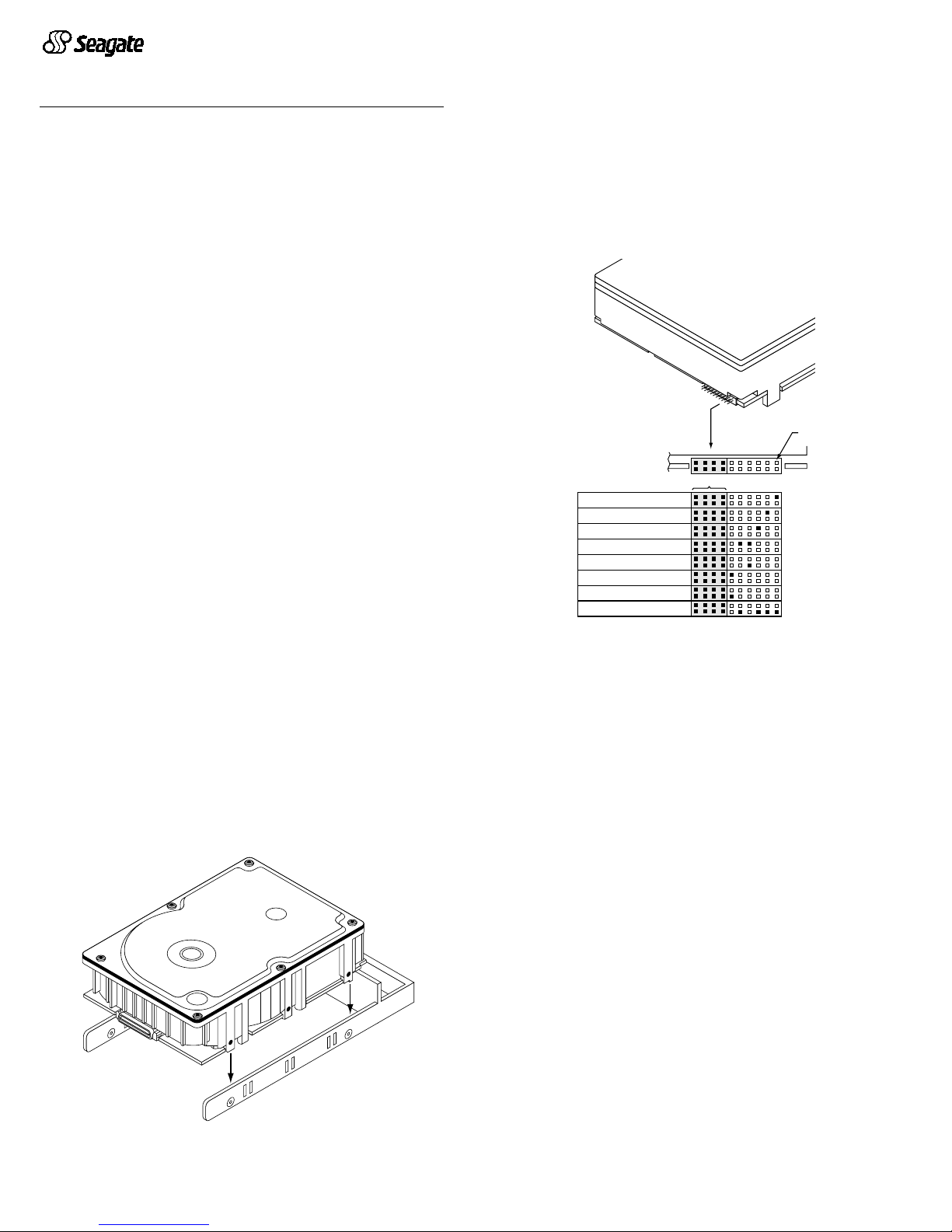
3. Connect LE Ds (optional)
Note.
This is an optional step. The drive will work fine without the LEDs
connected to the drive.
The drive supplies pins that you can use to connect fault and active LEDs.
This allows you to monitor drive fault conditions and activity. The actual LED
is external to the dri ve.
[1] The drive has a 2.2K ohm resistor in series with this LED driver. Tie the
minus side of an external high-efficiency LED (i.e., 2ma) to this pin.
Connect the plu s side of the LED to +5 V.
[2] An external current-limiting resistor is required when connecting an
LED to t his pin. Th e m inu s side o f th e r e s is t or /L E D co mb inatio n is c on nected to this pin. Connect the plus side to +5V.
[3] Jumper storage location (across pins 2 and 4).
Figure 2. LED indicator connector
Fault LED Signal
The drive activates the fault LED Ou t signal when:
• the drive de tects f ailure of both ports
• the drive detects an internal failure
• the drive receives the appropriate fault LED command from the host
Active LED signal
The drive activates the active LED signal as indicated below.
Normal command activity LED status
Spun down and no activity ............. Slow blink (20% on and 80% off)
Spun down and activity .................. On
(comm an d execut ing )
Spun up and no activity.................. On
Spun up and activity ....................... Off
(comm an d execut ing )
Spinning up or down....................... Blinks steadily (50% on and 50% off)
Format in progress ......................... Toggles on/off
(each cy li nder chan ge )
J6
Drive
Front
Pin 1
Port A Bypass LED [1]
Reserved
Port B Bypass LED [1]
Fault LED [1]
Reserved
Active LED [2]
+5V
Active LED [1]
Ground [3]

4. Format the drive
The drive has been low level formatted at the factory. You do not need to
perform another low level format on this drive unless you decide to perform
certain diagnostics through the host adapter. If you do decide to perform a
low level form at, do no t abor t th e format as thi s is like ly to make the d rive
inoperabl e. A low level for mat, w ith verify tur ned on, w ill typ ically take four
hours.
Protect again s t power failure or other power interruptions during the f ormat.
a. T urn on DC power to the host system.
b. Boot the system from a system floppy, CD, or from a previously installed
hard disc drive if there is one.
c. Format the drive.
Caution.
Formatt ing a dr ive eras es all us er data. Be sure t hat you un derstand t his pr in ciple b efor e formatti ng any h ard dis c dr ive. I t is no t
necessary to format a drive that previously has been used to
store data, unless your intention is to erase all user data. S eagate
is not responsible for lost user data.
Cheetah disc dr ives a re designed to operate with a variety of operating systems. Please refer to your system or Fibre Channel host adapter (controller)
manual for information about formatting and setting up the drive for use with
your particular operating system.
Hot plugging the drive
This drive features hot plugging capabilities which allows you to insert and
remove the drive without powering down the host system. Any time a drive
is inserte d or r emoved fr om a F ib re Chan nel lo op, a sh ort loop in terrupti on
occurs and the loop resynchronizes automatically to accommodate the
added (or rem oved ) dri ve.
Drive startup options
The drive’s motor will start spinning the discs based on the status of two signals set by the host adapter. These two signals are called Start_1 and
Start_2. There are four options as described belo w.
Option Start_2 Start_1 Motor spin function
1........... Low .......Low ........Motor spins up at DC power on.
2 . .......... High ...... Low ........ M otor spins up wh en the host adap ter sends
the SCSI Start command.
3 ........... Low ....... High........ Motor spins up after a delay of 12 seconds
times the physical address of the drive.
4........... High ......High........ The drive will not spin up.
Most systems that host only a couple of drives use option 1 to enable all of
the drive s t o st art up im m ediatel y wh en pow er is a pplied to th e drives. Sy s tems hosting larger numbers of drives may be configured to start drives at
various times to avoid overloading the capabilities of the host system’s
power supply.
If you want to change the startup option for the drive, please refer to the
docum enta tio n prov ided with yo ur Fib re C han nel host ad apte r or host sy stem.
Troubleshooting
•
Drive d oes not spi n up.
Remove and then reinsert the drive into the
drive bay on the ho st-supp lied c arrier or tray. Make sure the d rive ma kes
firm contact with the host’s FC backpane l co nnecto r.
•
Computer do es not s eem to re cogni ze the drive .
Verify that the d rive
is enabled b y the FC host adapter setup utility.
Seagate support services
For online information about S eagate products, visit www.se agate.com or email your disc questions to DiscSupport@Seagate.com
If you nee d he lp insta lling yo ur dri ve, consu lt your deal er firs t. If you need
additio nal help, call a S eagate tec hnical su ppor t special ist. Before calling,
note your system configuration and drive model number (ST173404FC/
FCV).
Africa +31-20-316-7222 Poland 00 800-311 12 38
Australia +61-2-9725-3366 Spain 900-98 31 24
Austria 0 800-20 12 90 Sweden 0 207 90 0 73
Belgium 0 800-74 876 Sw itzerland 0 800-83 84 11
Denmark 80 88 12 66 Singapore +65-488-7584
F rance 0 800-90 90 52 Taiwan +886-2-2514-2237
Germany 0 800-182 6831 Turkey 00 800-31 92 91 40
Hong Kong +852-2368 9918 United Kingdom 0 800-783 5177
Ireland 1 800-55 21 22 US A/Canada/ 1-800 SEAGATE or
Italy 800-790695 Latin America +1-405- 936-1234
Middle East +31-20-316-7222 Other European
Nether lands0 800-7 32-4283 countries +31-20-316-7222
Norway 800-113 91
Warranty.
Contact your place of purchase or our web site (above).
Return Merchandise Authorization (RMA).
Before returning t he drive, verify tha t it
is defective. Seagate Worldwide customer service centers are the only facilities authorized to service Seagate drives. Contact nearest center for return procedures and trade
regulations.
Shipping the drive
Caution.
Back up the data before shipping. Seagate assumes no respons ibility for
data lost dur ing shipping or serv ice. Shipping dr ive in an u napproved container voids
the warranty. Pack the drive with or iginal box and packing materials. Use no o ther
materials. This prevents electrical and physical damage in transit.
© 2000 Seagate Technology, Inc. All rights reserved
Publication number: 83329483, Rev. B, March 2000, Printed in U.S.A.
Seagate, Seagate Technology, the Seagate Logo, and Cheetah ar e either regist ered
trademarks or tr ademarks of Seagate Te chnology, Inc. All other trademarks are the
property of their respective owners.
 Loading...