

Page 1

••••••••••••••••••••••
Barracuda 36FC
••••••••••••••••••••••
Fibre Channel
••••••••••••••••••••••
Disc Drive
••••••••••••••••••••••
ST136475FC
••••••••••••••••••••••
••••••••••••••••••••••
Installation Guide
••••••••••••••••••••••
Page 2

Contents
Preface ........................................................................................ 1
Electrostatic discharge protection ............................................... 1
Important safety information and precautions........... .......... ........2
Wichti g e Sic h er h e i ts h in w ei se.... .. .......... .. ... .......... .. .......... .. ... ...... 4
Seagate Technology supp o rt ser v ic e s ... .......... .. ... ......... ... ......... .. 8
General description ................................................................... 14
Installing t he Barracuda 36FC drive.............. ............................16
Kühlung de s Sy s te ms........... .. .......... .. ... .......... .. .......... .. ... ......... 17
Troubleshooting......................................................................... 27
©1999 Seagate Technology, Inc. All rights reserved
Publication Number: 77767544, Rev. A
May 1999
Seagate, Seagate Technology, and the Seagate logo are registered trademarks of Seagate Technology, Inc. Barracuda,
SeaFAX, SeaFONE, SeaBOARD, and SeaTDD are either trademarks or registered trademarks of Seagate Technology, Inc. or
one of its subsidiaries. All ot her trademarks or registered trademarks are the property of their respective ow ners.
No part of this publication may be reproduced in any form without
written permission from Seagate Technology, Inc.
Page 3

Barracuda 36FC Ins tal lation Guide, Re v. A 1
Preface
This manual contains information for users of Seagate Barra-
cuda 36FC (Fibre Channel interface) disc drives. It provides
technical s upport in formation, performance specifications, i nstal-
lation instructions, and a troubleshooting section. Additional
information is available in the Barracuda 36FC Product Manual
(part number 77767543). Contact your Seagate sales represen-
tative if you need to order this publication.
Electrostatic discharge protection
Caution.
All drive electronic assemblies are sensitive t o static electricity,
due to the electrostatically sensitive devices used within the
drive circuitry. Although some devices such as metal -oxide semi -
conductors are extremely sensitive, all semiconductors, as well
as some resistors and capacitors, may be damaged or degraded
by ex posure to static elec tricity.
Electrost atic damage t o electroni c de vices may be caus ed by the
direct discharge of a charged conductor or by exposure to the
static fields surrounding charged objects. To avoid damaging
drive electronic assemblies, observe the following precautions
when installing or servicing the drive:
• Ground yourself to the drive whenever the drive electronics
are or will be exposed. Connect yourse lf to ground with a wrist
strap (Seagate part number 12263496). Connection may be
made to any grounded metal assembly. As a general rule,
remember that you and the drive electronics must all be
Removal of circuit boards by personnel not performing depot repair will damage components and may
void the war ranty.
Page 4

2 Barracuda 36FC Installation Guide, Re v. A
grounded to avoid potentially damaging static discharges.
• Do not remove any circuit boards from the drive.
• Never use an ohmmeter on any circuit boards.
• When installing the drive on a carrier or tray, discharge the
static electricity from the carrier or tray prior to inserting it into
the system.
Important safety information and precautions
Caution.
Use proper safety techniques for safe, reliable operation of this
unit.
The procedures in this manual and labels on the unit contain
warnings and cautions that must be carefully read and followed
to minimize or elimi nate the risk of personal injury. The warnings
point out conditions or practices that may endanger you or others. The cautions point out conditions or practices that may damage the unit, poss ibly making it unsafe for use.
Always observe the foll owing warnings and precautions:
• Follow all cautions and warnings in the procedures.
• Use sound safety practices when operating, installing, or
removing the unit.
• Use caution when troubleshooting a unit that has voltages
present. Turn off power to the unit before removing it.
• Ensure that the internal temperature of the rack or cabinet
does not exceed the limits defined for the drive when the drive
is mounted in an equipment rack or cabinet. When units are
stacked vertically, pay special attention to the top where temperatures are usually highest.
Use forced-air ventilation when bench-testing the
drive to ensur e proper cooling of drive components.
Page 5

Barracuda 36FC Ins tal lation Guide, Re v. A 3
• Follow the precautions listed above in “Electrostatic discharge
protection.”
• Do not remove any circuit boards from the drive chassis.
Return the entire drive for depot repair if any circuit board is
defective. Removal of circuit boards by personnel not performing depot repair will damage components and may void the
warranty.
• Do not remove the head and disc assembly (HDA) from the
drive. Return the entire drive for depot repair if the HDA is
defective.
• Do not attempt to disassemble the HDA. It is not field repairable. I f the sealed HD A is opened by personn el not performing
depot repair, this will damage components and void the warranty.
As a component, the drive is designed to be installed and operated in accordance with UL1950, EN60950, CAN\CSA C22.2
950-95, VDE0805 and IEC950.
Seagate takes all reasonable steps to ensure that its products
are certifiable to currently accepted standards. Typical applications of these disc drives include customer packaging and subsystem design. Safety agencies conditionally certify component
assemblies, such as the Barracuda disc drive, based on their
final acceptability in the end-use product. The subsystem
designers are responsible for meeting these conditions of
acceptabil ity in obtaini ng safety- regulatory agency compliance in
their end-use products and for certifying where required by law.
A necessary part of meeting safety requirement s is the provisi on
for overcurrent pr otection on drive SELV supply voltages .
Page 6

4 Barracuda 36FC Installation Guide, Re v. A
This unit is a component part and as such is not meant to com-
ply with FCC or similar national requirements as a stand-alone
unit. Engineering radiated emissions test results are available
through the Seagate Safety Department to assist the subsystem
designer.
Wichtige Sicherheitshinweise
Vorsicht.
Fremdbelüftung vorzusehen, um eine ausreichende Kühlung der
Laufwerkkom ponenten sicherzustellen.
Verwenden Sie geeignete Sicherheits- um den sicheren, zuverlässigen Betrieb dieser Einheit zu gewährleisten.
Die Verfahren in diesem Handbuch und die Aufkleber auf dem
Gerät enthalten Warn- und Vorsichtshinweise. Diese Hinweise
sind sorgfältig durchzulesen und zu beachten, um das Risiko
von Verletzungen auf ein Mindestmaß zu beschränken oder
ganz zu vermeiden. Die Warnhinweise machen auf Situationen
oder Praktiken aufmerksam, die Sie oder andere gefährden
könnten. Die Vorsichtshinweise machen auf Situationen oder
Praktiken aufmerksam, die Einheit beschädigen können, so daß
deren Gebrauch mit Risiko behaft et i st.
Die Warn- und Vorsichtshinweise sind nicht allumfassend! Es ist
uns einfach nicht möglich, alle Wartungsmethoden oder die
eventuellen Risiken jeder Methode zu kennen, zu beurteilen und
Sie entsprechend zu beraten. Aus diesem Grund haben wir auf
eine derartige umfassende Beurteilung verzichtet. Falls Sie ein
hier nicht beschriebenes Verfahren oder Werkzeug verwenden,
stellen Sie zuerst sicher, daß das gewählte Verfa hren weder Ihre
persönliche Sicherheit noch die Leistung der Einheit gefährdet.
Beim Testen des Laufwerks auf dem Prüftisch ist
Page 7

Barracuda 36FC Ins tal lation Guide, Re v. A 5
Beachten Sie in jedem Fall die folgenden Warn-und Vorsicht-
shinweise:
• Beachten Sie alle Warn- und Vorsichtshinweise in diesem
Handbuch.
• Treffen Sie beim Betrieb, bei der Installation oder bei der
Entfernung der Einheit angemessene Sicherheitsvorkehrungen.
• Wenn eine Einheit unter Spannung steht, gehen Sie bei der
Fehlerdiagnose besonders vorsichtig vor. Schalten Sie die
Einheit au s, bevor Sie m it den Installations-und Entfernungsar beiten beginne n.
• Wenn das Laufwerk in einem Einbaugestell oder Gehäuse
montiert ist, sorgen Sie dafür, d aß die Temperatur im Inneren
des Gestells oder Gehäuses die für das Laufwerk vorgegebenen Grenzwerte nicht übersteigt. Wenn Einheiten vertikal
übereinander betestigt werden, achten Sie besonders auf den
oberen Stapelbereich, da dort die Temperatur gewöhnlich am
höchsten ist.
• Befolgen Sie die oben unter “Electrostatic Discharge Protec-
tion” angegebenen Sicherheitsmaßnahmen.
• Nehmen Sie keine Platinen aus dem Laufwerk. Wenn eine
Platine defekt ist, muß das gesamte Laufwerk zur Reparatur
eingeschickt werden. Die Herausnahme von Platinen durch
andere Per sonen als die für die werkseitige Reparatur zustän-
digen kann zu einer Beschädigung der Komponenten und
Erlöschen des Garantieanspruchs führen.
• Die vormontierte Kopf- und Festplatteneinheit (HDA) nicht aus
dem Laufwerk nehme n! Falls die HDA besch ädi gt i st, schicken
Sie das gesamte Laufwerk zur Reparatur ein.
Page 8

6 Barracuda 36FC Installation Guide, Re v. A
• Die HDA ist nicht vor Ort reparierbar und darf nicht auseinandergenommen werden! Öffnen der versiegelten HDA durch
andere Per sonen als die für die werkseitige Reparatur zustän-
digen hat eine Beschädigung der Komponenten und
Erlöschen des Garantieanspruchs zur Fo lge.
Als Teilkomponente ist diese s Laufwe rk für di e Insta llation und
den Betrieb in Übereinsti mmung mit UL 1950, EN60 950,
CAN\CSA C22.2 950-95 und VDE0805 vorgesehen.
Seagate ist ständi g bemüht, die Zulassungsfähigkeit von
Seagate-P rodukten im Rahme n der geg enwär tig ge ltenden
Standa rd s zu gewährleisten. Zu den typischen Anwendungen
dieser Festplattenwerke zählen Systemeinbau durch den
Kunden und die K on strukti on von Unter systemen. Sicherh eitsbe hörden gewähren eine bedingt e Zulass ung für Komponenten wie
das Barracuda-Fest plattenlaufwerk vorbehaltli ch der endgültigen
Zulasssun g im E ndprod ukt . Design er von Un tersyst eme n sind
dafür verantwortlich, die Voraussetzungen für die Einhaltung
sicherheits- oder aufsichtsbehördlicher Vorschriften in ihren
Endprodukten und - falls gesetzlich vorgeschrieben - für die
Zulass ung zu scha ffen. Eine Gr un dvorau ss etzu ng zur E in haltung der Sicherheitsanforderungen ist die Bereitstellung eines
Überlastschutzes für die SELV-Versorgungsspannungen des
Laufwerks.
Dieses Gerät ist eine Baugruppe und unterliegt als solche ni cht
den Anforderungen der FCC oder ähnlicher nationaler Beh örden
für eigenständige Geräte. Technische Testergebnisse zu elektro-
magnetische Str ahlung si nd für Designer von Unte rsyst emen auf
Anfrage von der Seagate-Sicherheitsabteilung erhältlich.
Page 9

Barracuda 36FC Ins tal lation Guide, Re v. A 7
European Union Compliance
If this model has the CE Marking, it complies with the European
Union requirements of the Electromagnetic Compatibility Directive 89/336/EEC of 03 May 1989 as amended by Directive 92/31/
EEC of 28 April 1992 and Directive 93/68/EEC of 22 July 1993.
Australian C-Ti ck
If this model has the C-Tick Marking, it complies with the Australia/New Zealand Standard AS/NZS3548 1995 and meets the
Electromagnetic Compatibility (EMC) Framework requirements
of Australia’s Spectrum Management Agency (SM A).
Seagate uses an independent laboratory to confirm compliance
to the above directives. The drive was tested in a representative
system for typical applications. The selected system represents
the most popular characteristics for test platforms. The system
configurations include:
• 486, P entium, and P owerPC Microprocessors
• 3.5-inch Flo ppy Disc Driv e
• Keyboard
• Monitor/Display
• Mouse
• Printer
Although the test system with this Seagate model complies to
the directives, we cannot guarantee that all systems will comply.
The computer manufacturer or system integrator shall confirm
EMC compliance and provide CE Marking for their product.
Page 10

8 Barracuda 36FC Installation Guide, Re v. A
Seagate Technology suppo rt services
Online Se r vices
Internet
For online information about Seagate products, visit
www.seagate.com or e-mail your disc or tape questions to:
Presales Support:
Disc: http://www.seagate.com/support/email/
email_presales.shtml
Tape: http://www.seagate.com/support/email/
email_tape_presales.shtml
[email protected]
Technical Support
Disc: http://www.seagate.com/support/email/
email_disc_support.shtml
Tape: http://www.seagate.com/support/email/
email_tape_support.shtml
SeaBOARD®
information about Seagate disc and tape drive products and is
available 24 hours daily. Set your communications software to
eight data bits, no parity and one stop bit (8-N-1). This service is
availa ble worldwide.
:
is a computer bulletin board system that contains
or
DiscPresales@Seag ate.com
or
or
or
Automated S er vices
SeaFONE
800-732-4283) to access our automated self-help services.
Using a touch-tone phone, you can find answers to service
1-800-SEAGATE)
® (
is Seagate's toll-free number (1-
Page 11

Barracuda 36FC Ins tal lation Guide, Re v. A 9
phone numbers, commonly asked questions, troubleshooting
tips and specifications for disc drives and tape drives 24 hours
daily. International callers can reach this service by dialing +1405-936-1234.
SeaFAX
touch-tone phone, you can obtain technical support information
by retu rn FAX 24 hours daily. This service is available worldwi de.
®
is Seagate's automated FAX delivery system. Using a
Presales Support
Our Presales Support staff can help you determine which
Seagate products are best suited for your specific application or
computer sys tem.
Seagate Express
You can purchase select tape products and tape accessories
through Seagate Express 24 hours daily by calling 1-800-5310968 or by faxing your order to: +1-972-481-4812.
T e c hnical Support
If you need help installing your drive, consult your dealer. Dealers are familiar with their unique system configurations and can
help you with system conflicts and other technical issues. If you
need additi onal help , you can talk to a Seagate technical support
specialist. Before calling, note your system configuration and
drive model number (ST
SeaTDD™(+1-405-936-1687)
for the deaf (TDD). You can send questions or comments 24
hours daily and exchange messages with a technical suppor t
####).
is a telecommunications device
Page 12

10 Barracuda 36FC Inst allation Guide, Rev. A
specialist from 8:00 A.M. to 12:15 P.M. and 1:30 P.M. to 6:00
P.M. (central time) Monda y through Friday.
Customer Service (C SO)
Warranty Repa ir
Seagate offers worldwide customer support for Seagate drives.
Seagate direct OE M , Di stribution and System Integrator customers should contact their Seagate service center representative
for warranty information. Other customers should contact their
place of purchase.
Authorized Service Centers
If you l ive outside the US, you can contact a n Authorized Servi ce
Cent e r for service or re pair.
USA/Canada/Latin America Support Services
Presales Support
Disc:
1-877-271-3285 or FAX: +1-405-936-1683
+1-405-936-1210
Tape:
1-800-626-6637 or FAX: +1-714-641-2410
+1-714-641-2500
Technical Suppor t (SeaFONE)
1-800-SEAGATE or +1-405-936-1234 (for specific product
phone number)
FAX:
Disc: +
1-405-936-1685;
SeaFAX 1-800-SEAGATE
SeaTDD +1-405-936-1687
SeaBOARD
Disc: +
Tape:
+1-405-936-1683
1-405-936-1600;
Tape:
+1-405-936-1630
Page 13

Barracuda 36FC Ins tal lation Guide, Re v. A 11
Warranty Repa ir
USA 1-800-468-3472 FAX: +1-405-949-6740
Mexico an d
Latin America +1-405-949-7758 F AX: +1-405-949-6738
Authorized Service Centers
Brazil
MA Informatica
Canada
Memofix
Adtech
1
1
+55-21-516-6649 F AX: +55-21-516-5280
+1-905-660-4936 F AX: +1-905-660-4951
+1-905-812-8099 or F AX: +1-905-812-7807
1-800-624-9857
European Support Services
For European customer support, dial the toll-free number for
your specific country for presales support, technical support,
SeaFAX and warranty repair.
If your country is not listed here, dial our European call center at
+31-20-316-7222 from 8:30
time) Monday through Friday. The European call center is
located in Amsterdam, The Netherlands.
Call Center
Austria 0 800-20 12 90
Belgium 0 800-74 876
Denmark 80 88 12 66
Fr ance 0 800-90 90 52
Germany 0 800- 182 6831
A.M
. to 5:00 P.M. (European central
1. Authorized Service Centers
Page 14

12 Barracuda 36FC Inst allation Guide, Rev. A
Ireland 1 800-55 21 22
Italy 1 677 90 695
Netherlands 0 800-732 4283
Norwa y 800-113 91
Poland 00 800-311 12 38
Spain 900-98 31 24
Sweden 0 207 90 073
Switzerland 0 800-83 84 11
Turkey 00 800-31 92 91 40
United Kingdom 0 800-783 5177
SeaBOARD
Germany +49-89-1409331
Fax Services—All European Countries
Presales/Technical Supp ort/Warranty Repair +31-20-653-3513
Africa/Middle East Support Services
For presales, technical support, warranty repair and FAX services in Af rica and the Middle Eas t, dial our Euro pean call center
at +31-20-316-7222 from 8:30 a.m. to 5:00 p.m. (European central time) Monday through Friday, or send a FAX to +31-20-653-
3513. The European call center is located in Amsterdam, The
Netherlands.
Asia/Pacific East Support Services
Technical Suppor t
Australia +61-2-9725-3366 F AX: +61-2-9725-4052
Hong Kong +852-2368 9918 FAX: +852-2368 7173
Japan — F AX: +81-3-5462-2979
Page 15

Barracuda 36FC Ins tal lation Guide, Re v. A 13
Singapore +65-488-7584 FAX: +65-488-7528
Taiwan +886-2-2514-2237 F AX: +886-2-2715-2923
SeaFAX
Australia +61-2-9756-5170
Warranty Repa ir
Japan +81-3-5462-2904 F AX: +81-3-5462-2979
Asia/Pacific and +65-485-3595 FAX: +65-488-7503
Australia
Page 16
14 Barracuda 36FC Inst allation Guide, Rev. A
General description
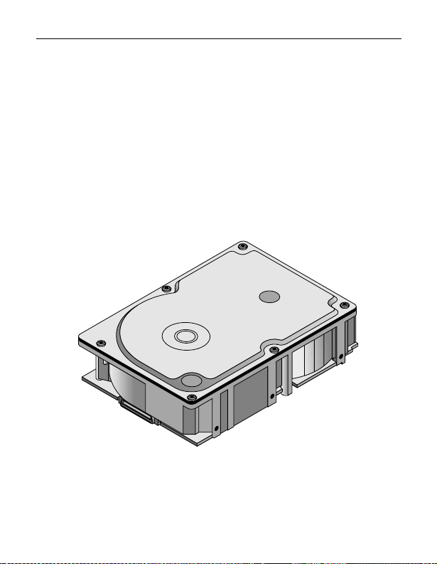
Barracuda 36FC disc drives are hi gh-speed, r andom -access dig ital-data storage devices designed to be used within a Fibre
Channel host system.
The drive is a component for installation in an enclosure
designed for the drive. The disc drive must receive adequate
cooling (refer to “Providing adequate cooling”) and it must be
sufficiently grounded and shielded from emissions. The Barracuda 36FC Product Manual (part number 77767543) contains
guidelines for a properly designed enclosure.
Figure 1: Barracuda 36FC disc drive
Page 17

Barracuda 36FC Ins tal lation Guide, Re v. A 15
Characteristics
ST136475FC
Interface Fibre Channel
Capacity
Unform atted (Gb ytes)
Formatted (Gbytes)
1
43.2
36.4
Recording
Cylinders (user )
Read/w rite data heads
Avg bytes/t ra ck
11,721
20
186,000
Access time
Average read (msec)
Average write (msec)
7.7
8.4
Disc rotation
RPM
Average latency (msec)
7,20 0 (+/- 5%)
4.17
Data transfer rate
Maxi mu m instantaneous
106
(Mbytes/sec, per port)
1. The specified formatted capacities are calculated with the standard OEM
sector size (512 bytes per logical block) and sparing.
ST136475FC
1
DC power requirements(±5%)
Maximum start current
Maximum operating current
Average idle current
1. For more detailed power information, refer to the Barracuda
36FC Product Manual, publication number 77767543.
+5 V +12 V
0.75A
0.75A
0.7A
2.63A
1.30A
0.95A
Page 18

16 Barracuda 36FC Inst allation Guide, Rev. A
Installing the Barracuda 36FC drive
To install a Barracuda 36FC drive, simply plug the drive directly
into your system’s Fibre Channel backpanel 40-pin single con-
nector attachment (FC-SCA). There are no jumpers or terminators on the drive, and power is supplied through the connector.
Table 1 on page 25 lists the pin descriptions of the 40-pin FCSCA.
Read the following general information topics to ensure your
drive is installed properly:
• Providing adequate cooling
• Mounting the drive
• Formatting t he drive
Providing adeq uate cooling
The enclosure design must ensure adequate cooling for the
drive. The maximum ambient temperature is 50
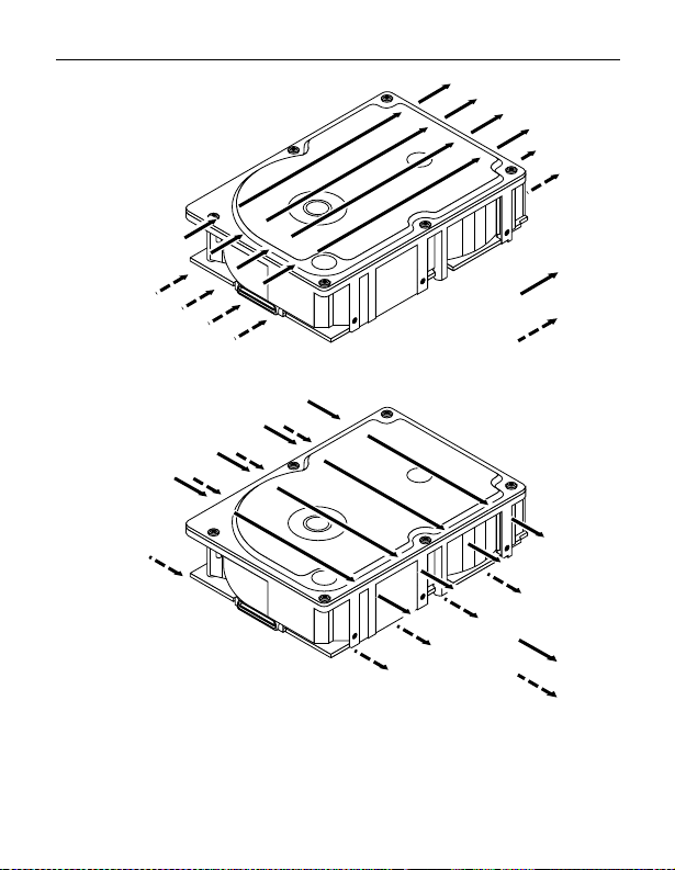
rated MTBF). Refer to Figure 2 on page 18 for an illustration
showing suggested air flow patterns.
The drive’s product manual (77767543) describes how to evalu-
ate the air-flow design. The evaluation consists of ensuring that
the case temperatures of certain critical components remain
within acceptable limits during drive operation.
We recommend orienting the drive or directing the air flow in a
way that creates the least amount of air-flow resistance while
providing air flow above the circuit boards and around the head
and disc assembly (HDA). Also, choose the shortest possible
path between the air inlet and exit. This minimizes the distance
traveled by air that is heated by the dr ive and by other nearby
heat sources.
o
C (30oC for the
Page 19

Barracuda 36FC Ins tal lation Guide, Re v. A 17
Figure 2 shows one design approach with one or m ore fan s used
to generate air flow. The air-flow pattern can be created by the
fans either pushing or drawing air. The overall flow pattern must
be directed from side to side in most FC-SCA systems.
Kühlung des Syst ems
Die Gehäusekonstruktion muß eine ausreichende Kühlung des
Laufwerkes ge währlei sten. Die Umgebungstemperatur darf max -
o
imal 50
Die Produkthandbuch Barracuda 36FC (Dokument 77767543)
enthalten Anweisungen zur Beurteilung der Luftstromkonstruktion. Die Beurteilung muß sicherstellen, daß sich die Gehäuse-
temperatur bestimmter kritischer Komponenten bei
Laufwerkbetrieb innerhalb zugelassener Grenzen hält.Wir
empfehlen, das Laufwerk so zu orientieren oder den Luftstrom
so zu lenken, daß der geringste Luftstromwiderstand vonvorne
nach hinten oder v on hinten nach vorne verlaufen.
C betragen (30oC für der MTBF).
Page 20
18 Barracuda 36FC Inst allation Guide, Rev. A
Above unit
Note. Air flows in the direction shown (back to front)
or in reverse direction (front to back)
Note. Air flows in the direction shown or
in reverse direction (side to side)
Figure 2: Suggested air flow
Abbildung 2. Empfohlener Luftstrom verl auf
Under unit
Above unit
Under unit
Page 21

Barracuda 36FC Ins tal lation Guide, Re v. A 19
Mounting the drive
Do not touch the connector pins or any components on the control board without observing static-discharge precautions.
Always handle the drive by the frame only.
You may mount the drive in any orientation (horizontally, vertically, or any combination ther eof); however, you m ust ensur e that
the drive receives adequate air flow for cooling.
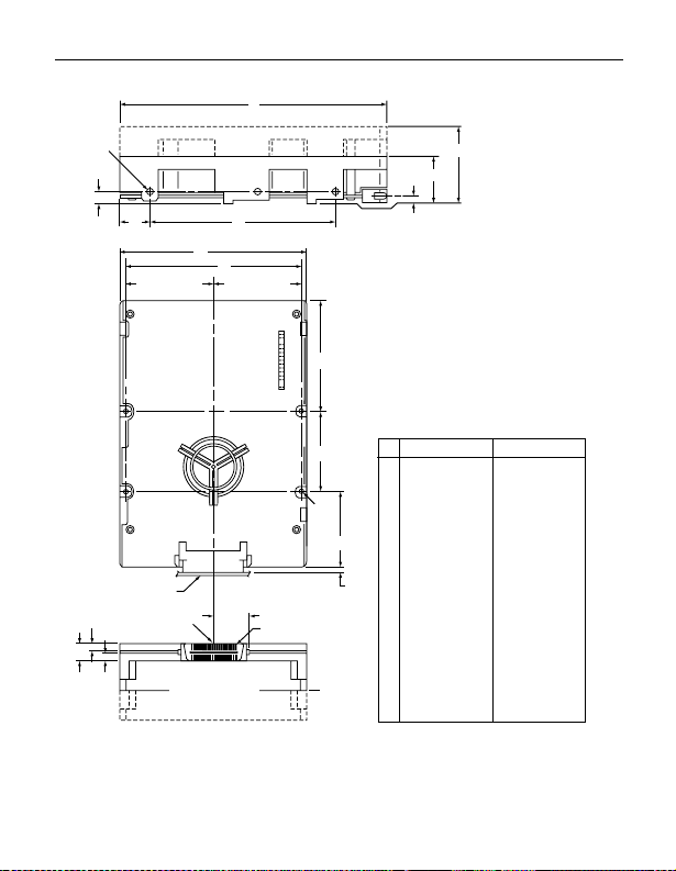
Mount the drive to the host system’s chassis using four 6-32
UNC screws. Two mounting holes are in each side of the drive
and there are four mounting holes in the bo tt om of the drive. See
Figure 3.
The maximum length that the screws should extend into the
chassis mounting holes is 0.15 inch (3.81 mm), measured from
the outer surface of the chassis. Tighten the screws down
evenly. Do not over-tighten or force the screw if it does not seem
to screw in easily.
Installation des Laufwerkes
Beachten Sie bei m Han dhaben und Anfassen der Anschlußstifte
und Komponenten die Vorsichtsmaßnahmen zur Verhinderung
statischer Aufladung. Fassen Sie das Laufwerk nur am Rahmen
an.
Das Laufwerk kann in beliebiger Orientierung (horizontal, vertikal oder schräg) installiert werden; jedoch muß dafür gesorgt
werd en, daß ein ausreichender Luftstrom zur Kühlung des Laufwerkes v orhanden ist.
Befestigen Sie das Laufwerk mit vier 6-32-UNC-Schrauben am
Gehäuse des Host-Systems. Die beiden Seiten des Laufwerkes
sind mit jeweils zwei Befestigungslöcher versehen, die
Page 22

20 Barracuda 36FC Inst allation Guide, Rev. A
Unterseite des Laufwerkes weist vier wei tere Befe stigungslöcher
auf. Siehe Abbiludung 3.
Gemessen von der Außenfläche des Gehäuses dürfen die
Schrauben maximal 3,81 mm in die Befestigungslöcher des
Gehüuses hineinragen. Die Schrauben müssen gleichmäßig,
jedoch nicht zu fest, angezogen werden. Wenn sich eine
Schraube nicht ohne Widerstand einschrauben läßt, sind die
Gewinde nicht korrekt aneinander ausgerichtet.
Page 23
Barracuda 36FC Ins tal lation Guide, Re v. A 21
A
[1]
F
D
Motherboard Ref.
P
R[3]
Common centerline
(X axis) direction
E
B
H
1.875±.0051.875±.005
(.809)
[4]
in the horizontal
of the drive
Pin 1
Notes:
Mounting holes three on each side,
[1]
6-32 UNC. Max screw length into
side of drive is 0.15 in. (3.81 mm).
Mounting holes four on bottom,
[2]
6-32 UNC. Max screw length into
bottom of drive is 0.15 in. (3.81 mm).
Keep-out zone for any components
[3]
J
on backplane.
Connector is centered on module
[4]
and flush with end of base.
K
[2]
Low
Profile
Half
Height
A
B
C
D
E
F
N
H
.136
J
K
L
M
N
P
R
Figure 3: Dimensions
Abbildung 3: Laufwerkabm essungen
M
C
L
Inches Millimeters
5.75
4.00
1.026
.620
4.000
.250
3.750
2.380
1.750
0.181
1.622
1.620
.1215
.1215
±
±
max
ref
±
+
–
±
±
±
+
–
+
–
±
max
max
0.025
0.015
0.010
0.011
0.005
0.010
0.010
0.010
0.013
0.007
0.027
0.021
0.025
146.05
101.6
26.060
15.748
101.600
6.350
95.25
60.45
44.450
4.590
41.20
41.150
3.080
3.080
± .64
± .381
max
ref
± .25
+ .28
– .12
± .25
± .25
± .50
+ .33
– .18
+ .69
– .53
± .64
max
max
Page 24

22 Barracuda 36FC Inst allation Guide, Rev. A
Inserting the drive
Most systems provide a way to insert the drive using a carrier or
tray which allows the drive to be hot-plugged into the system’s
Fibre Channel 40-pin single connector attachment (FC-SCA).
Refer to your system documentation about the method they provide and follow their instructions.
When installing the drive on a carrier or tray, discharge the static
electricity from the carrier or tray prior to inserting it into the system.
Formatting the drive
Warning.
Note.
1. Supply DC power to the drive (pow er is supplied to the drive
through the 40-pin FC-SCA).
2. Format the disc drive. This drive is designed to operate with
a variety of operating systems. Refer to your system and
Fibre Channel controller manual for information about
selecting and formatting the drive.
Formatting a drive erases all user data. Be sure that
you understand this principle before formatting any
hard disc drive (it is not necessary to format a drive
which has previously been used to store data
unless you int end to erase all user dat a).
Seagate is not responsible for lost user data.
Page 25

Barracuda 36FC Ins tal lation Guide, Re v. A 23
Enabling write cache
Write caching is a feature that allows the drive to transfer write
data to its own cache, tell the controller that the task is complete,
and then actually complete the write at a later time. This
improves write performance by freeing the CPU to go on to its
next com mand.
Warning.
OEM drives are shipped with write cache disabled by default to
enhance data integrity. If you want to enable the write cache,
refer to your system’s drive controller and software utility documentation. Seaga te prov ides an ASPI util ity that y ou can use in a
PC compatible system to enable the write cache. It is available
on Seagate’s web site (refer to “Seagate Technology support
services” on page 8).
Information can be lost if you enable write cache
and there is a system failure (for example, power
failure) before the data has actually been physically
written to the disc.
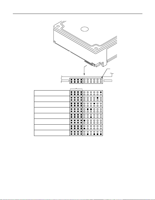
Connecting remot e LEDs
You can connect remote LEDs using J6 (see Figure 4).
Connect the anode (usually the longer LED connector) to the
+5V pin, and the cathode to the appropriate LED output pin. For
example, if you want to attach an LED which indicates drive
activity, connect the LED’s anode connector to J6 pin 11 and the
cathode to J6 pin 12 or connect to J6 pin 8 through an appropriate external current-limiting resistor.
Note.
The LED is on when the drive is idle and off when the
drive is processing commands .
Page 26
24 Barracuda 36FC Inst allation Guide, Rev. A
Drive
Front
Pin 1
J6
Reserved
Port A Bypass LED [1]
Port B Bypass LED [1]
Fault LED [1]
Reserved
Active LED [2]
+5V
Active LED [1]
Ground [3]
[1] The drive has a 2.2K ohm re sisto r in serie s with this LED driver .
Tie the minus side o f an ex ter nal hi gh- effici ency LE D (i.e., 2ma)
to this pin. Connect the plus side of the LED to +5V.
[2] An external cu rrent-l imitin g r esist or is r equi red whe n c onne cti ng
an LED to this pin. Connect the mi nus side of the resistor/L ED
combination to this pin. Connect the plus side to +5V. This pin is
connected in parallel wi th the s ignal of the s ame na me in the interface connector (J1).
[3] Jumper storage location (across pins 2 and 4).
Figure 4: LED indicator connector (J6)
Page 27

Barracuda 36FC Ins tal lation Guide, Re v. A 25
Table 1: FC-SCA pin descriptions
Pin/contact Signal name Signal type
1* –EN bypass port A TTL output
2* 12 Volts
3* 12 Volts
4* 12 Volts
5* –Parallel ESI
6* Ground
7* Active LED out Open collector out
8* Reserved
9* Start_1 TTL input
10* Start_2 TTL input
11* –EN bypass port B TTL output
12* SEL_6 TTL input/output
13* SEL_5 TTL input/output
14* SEL_4 TTL input/output
15* SEL_3 TTL input/output
16* Fault LED out Open collector out
17* Res e rved NC
18* Reser ved NC
19* 5 Volts
20* 5 Volts
21 12 Volts charge
22 Ground
23 Ground
24* +Port A_in Diff. PECL input pair
25* –Port A_in
[1]
Page 28
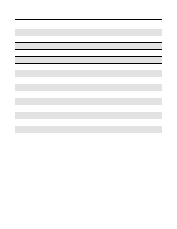
26 Barracuda 36FC Inst allation Guide, Rev. A
Pin/contact Signal name Signal type
26 Ground
27* +Port B_in Diff. PECL input pair
28* –Port B_in
29 Ground
30* +Port A_ou t Diff. PECL output pair
31* –Port A_out
32 Ground
33* +Port B_out Diff. PECL output pair
34* –Port B_out
35 Ground
36 SEL_2 TTL input/output
37 SEL_1 TTL input/output
38 SEL_0 TTL input/output
39 Reserved NC
40 5 Volts charge
*Short pins in mating backpanel connector.
[1] This pin may be connected to external logic to detect the presence of the drive.
The drive connects this pin to the common ground.
Page 29

Barracuda 36FC Ins tal lation Guide, Re v. A 27
Troubleshooting
Before calling Seagate Technical Support, please read the possibilities discussed below. The suggestions presented here will
resolve the majority of instal lat ion problems .
General installation troubleshoo t ing
Check system compatibility.
•
device. Check your system documentation to ensure that it
supports FC devices.
Check the physical attachment.
•
properly mated with the backpanel Fibre Channel single connector attachment (FC-SCA).
Check to ensure that drive is receiving power.
•
drive into your system. Listen carefully for the sound of the
drive motor spinning up. If the drive motor does not spin up,
check the power supply. If your power supply is functioning
properly, but the drive does not spin up, contact the company
from which you pur chased the drive.
Check your system or backpanel documentation to
•
ensure you have set options in accordance with the manufacturer’s recommendations.
addresses, are set at the backpanel within the host system or
through system soft ware . Chec k your host system docum entation about how to set th ese options in your particular system.
This is a Fibre Channel (FC)
Ensure that the drive is
Inser t the
All device options, including
Page 30

Page 31

Page 32

Seagate Technology, Inc.
920 Disc Drive, Scotts Valle y, CA 95066-4544, USA
Publication Number: 77767544, Rev. A, Printed in USA
 Loading...