

Page 1

. . . . . . . . . . . . . . . . . . . . . . . . . . . . . . . . . . . . . . . . . . . . . . . . .
Barracuda 36 Family:
. . . . . . . . . . . . . . . . . . . . . . . . . . . . . . . . . . . . . . . . . . . . . . . . .
ST136475LW/LC
. . . . . . . . . . . . . . . . . . . . . . . . . . . . . . . . . . . . . . . . . . . . . . . . .
. . . . . . . . . . . . . . . . . . . . . . . . . . . . . . . . . . . . . . . . . . . . . . . . .
Product Manual, Volume 1
. . . . . . . . . . . . . . . . . . . . . . . . . . . . . . . . . . . . . . . . . . . . . . . . .
Page 2

Page 3

. . . . . . . . . . . . . . . . . . . . . . . . . . . . . . . . . . . . . . . . . . . . . . . . .
Barracuda 36 Family:
. . . . . . . . . . . . . . . . . . . . . . . . . . . . . . . . . . . . . . . . . . . . . . . . .
ST136475LW/LC
. . . . . . . . . . . . . . . . . . . . . . . . . . . . . . . . . . . . . . . . . . . . . . . . .
. . . . . . . . . . . . . . . . . . . . . . . . . . . . . . . . . . . . . . . . . . . . . . . . .
Product Manual, Volume 1
. . . . . . . . . . . . . . . . . . . . . . . . . . . . . . . . . . . . . . . . . . . . . . . . .
Page 4

© 1997-2000 Seagate Technology, LLC All rights reserved
Publication number: 77767528, Rev . C
August 2000
Seagate, Seagate Technology, and the Seagate logo are re gistered trademar ks of Seagate Technology,
LLC. Barracuda, SeaFAX, SeaFONE, SeaBOARD, and SeaTDD are either trademarks or registered
trademarks of Seagate Technology, LLC, or one of its subsidiaries. All other trademarks or registered
trademarks are the property of their respective owners.
Seagate reser ves the right to change, without notice, product offerings or spe cifications. No part of this
publication may be reproduced in any form without written permission of Seagate Technology, LLC.
Page 5

Revision status summary sheet
Revision Date Writer/Engineer Sheets Affected
Rev. A 04/20/99 D. Ashby/P. Kusbel 1/1, v thru viii, 1-82
Rev. B 09/02/99 D. Ashby/P. Kusbel 25
Rev. C 08/22/2000 K. Schweiss/B. Reynolds ii, 1, 36, 42, 69-71, and backcover
Notice.
Product Manual 77767528 is Volume 1 of a two volume document with the SCSI Interface information in
the Volume 2 SCSI Interface Product Manual, part number 77738479.
If the SCSI Interface information is needed the Volume 2 Interface Manual should be ordered,
part number 77738479.
Page 6

Page 7

Barracuda 36 Product Manual, Rev. C vii
Table of Contents
1.0 Scope . . . . . . . . . . . . . . . . . . . . . . . . . . . . . . . . . . . . . . . . . . . . . . . . . . . . . . . . . . . . . . . . . . . . . . . . . . 1
2.0 Applicable standards and reference documentation. . . . . . . . . . . . . . . . . . . . . . . . . . . . . . . . . . . . 3
2.1 Standards. . . . . . . . . . . . . . . . . . . . . . . . . . . . . . . . . . . . . . . . . . . . . . . . . . . . . . . . . . . . . . . . . 3
2.1.1 Electromagnetic compatibility . . . . . . . . . . . . . . . . . . . . . . . . . . . . . . . . . . . . . . . . . . 3
2.1.2 Electromagnetic susceptibility. . . . . . . . . . . . . . . . . . . . . . . . . . . . . . . . . . . . . . . . . . 3
2.2 Electromagnetic compliance . . . . . . . . . . . . . . . . . . . . . . . . . . . . . . . . . . . . . . . . . . . . . . . . . . 3
2.3 Reference documents . . . . . . . . . . . . . . . . . . . . . . . . . . . . . . . . . . . . . . . . . . . . . . . . . . . . . . . 4
3.0 General description. . . . . . . . . . . . . . . . . . . . . . . . . . . . . . . . . . . . . . . . . . . . . . . . . . . . . . . . . . . . . . . 5
3.1 Standard features. . . . . . . . . . . . . . . . . . . . . . . . . . . . . . . . . . . . . . . . . . . . . . . . . . . . . . . . . . . 7
3.2 Media characteristics . . . . . . . . . . . . . . . . . . . . . . . . . . . . . . . . . . . . . . . . . . . . . . . . . . . . . . . . 7
3.3 Performance. . . . . . . . . . . . . . . . . . . . . . . . . . . . . . . . . . . . . . . . . . . . . . . . . . . . . . . . . . . . . . . 7
3.4 Reliability . . . . . . . . . . . . . . . . . . . . . . . . . . . . . . . . . . . . . . . . . . . . . . . . . . . . . . . . . . . . . . . . . 7
3.5 Unformatted and formatted capacities . . . . . . . . . . . . . . . . . . . . . . . . . . . . . . . . . . . . . . . . . . . 8
3.6 Programmable drive capacity. . . . . . . . . . . . . . . . . . . . . . . . . . . . . . . . . . . . . . . . . . . . . . . . . . 8
3.7 Factory installed accessories . . . . . . . . . . . . . . . . . . . . . . . . . . . . . . . . . . . . . . . . . . . . . . . . . . 8
3.8 Options (factory installed). . . . . . . . . . . . . . . . . . . . . . . . . . . . . . . . . . . . . . . . . . . . . . . . . . . . . 8
3.9 Accessories (user installed) . . . . . . . . . . . . . . . . . . . . . . . . . . . . . . . . . . . . . . . . . . . . . . . . . . . 8
4.0 Performance characteristics . . . . . . . . . . . . . . . . . . . . . . . . . . . . . . . . . . . . . . . . . . . . . . . . . . . . . . . 9
4.1 Internal drive characteristics (transparent to user). . . . . . . . . . . . . . . . . . . . . . . . . . . . . . . . . . 9
4.2 SCSI performance characteristics (visible to user) . . . . . . . . . . . . . . . . . . . . . . . . . . . . . . . . . 9
4.2.1 Access time . . . . . . . . . . . . . . . . . . . . . . . . . . . . . . . . . . . . . . . . . . . . . . . . . . . . . . . 9
4.2.2 Format command execution time (minutes) . . . . . . . . . . . . . . . . . . . . . . . . . . . . . . . 9
4.2.3 Generalized performance characteristics . . . . . . . . . . . . . . . . . . . . . . . . . . . . . . . . . 9
4.3 Start/stop time . . . . . . . . . . . . . . . . . . . . . . . . . . . . . . . . . . . . . . . . . . . . . . . . . . . . . . . . . . . . 10
4.4 Prefetch/multi-segmented cache control . . . . . . . . . . . . . . . . . . . . . . . . . . . . . . . . . . . . . . . . 11
4.5 Cache operation. . . . . . . . . . . . . . . . . . . . . . . . . . . . . . . . . . . . . . . . . . . . . . . . . . . . . . . . . . . 11
4.5.1 Caching write data . . . . . . . . . . . . . . . . . . . . . . . . . . . . . . . . . . . . . . . . . . . . . . . . . 12
4.5.2 Prefetch operation . . . . . . . . . . . . . . . . . . . . . . . . . . . . . . . . . . . . . . . . . . . . . . . . . 12
5.0 Reliability specifications . . . . . . . . . . . . . . . . . . . . . . . . . . . . . . . . . . . . . . . . . . . . . . . . . . . . . . . . . 13
5.1 Error rates . . . . . . . . . . . . . . . . . . . . . . . . . . . . . . . . . . . . . . . . . . . . . . . . . . . . . . . . . . . . . . . 13
5.1.1 Environmental interference. . . . . . . . . . . . . . . . . . . . . . . . . . . . . . . . . . . . . . . . . . . 13
5.1.2 Read errors. . . . . . . . . . . . . . . . . . . . . . . . . . . . . . . . . . . . . . . . . . . . . . . . . . . . . . . 13
5.1.3 Write errors. . . . . . . . . . . . . . . . . . . . . . . . . . . . . . . . . . . . . . . . . . . . . . . . . . . . . . . 13
5.1.4 Seek errors. . . . . . . . . . . . . . . . . . . . . . . . . . . . . . . . . . . . . . . . . . . . . . . . . . . . . . . 14
5.2 Reliability and service. . . . . . . . . . . . . . . . . . . . . . . . . . . . . . . . . . . . . . . . . . . . . . . . . . . . . . . 14
5.2.1 Mean time between failure . . . . . . . . . . . . . . . . . . . . . . . . . . . . . . . . . . . . . . . . . . . 14
5.2.2 Preventive maintenance . . . . . . . . . . . . . . . . . . . . . . . . . . . . . . . . . . . . . . . . . . . . . 14
5.2.3 Service life . . . . . . . . . . . . . . . . . . . . . . . . . . . . . . . . . . . . . . . . . . . . . . . . . . . . . . . 14
5.2.4 Service philosophy . . . . . . . . . . . . . . . . . . . . . . . . . . . . . . . . . . . . . . . . . . . . . . . . . 14
5.2.5 Service tools. . . . . . . . . . . . . . . . . . . . . . . . . . . . . . . . . . . . . . . . . . . . . . . . . . . . . . 14
5.2.6 Hot plugging Barracuda 36 disc drives . . . . . . . . . . . . . . . . . . . . . . . . . . . . . . . . . . 15
5.2.7 S .M.A.R.T. . . . . . . . . . . . . . . . . . . . . . . . . . . . . . . . . . . . . . . . . . . . . . . . . . . . . . . . 15
5.2.8 Product warranty. . . . . . . . . . . . . . . . . . . . . . . . . . . . . . . . . . . . . . . . . . . . . . . . . . . 16
6.0 Physical/electrical specifications . . . . . . . . . . . . . . . . . . . . . . . . . . . . . . . . . . . . . . . . . . . . . . . . . . 19
6.1 AC power requirements . . . . . . . . . . . . . . . . . . . . . . . . . . . . . . . . . . . . . . . . . . . . . . . . . . . . . 19
6.2 DC power requirements . . . . . . . . . . . . . . . . . . . . . . . . . . . . . . . . . . . . . . . . . . . . . . . . . . . . . 19
6.2.1 Conducted noise immunity . . . . . . . . . . . . . . . . . . . . . . . . . . . . . . . . . . . . . . . . . . . 20
6.2.2 Power sequencing . . . . . . . . . . . . . . . . . . . . . . . . . . . . . . . . . . . . . . . . . . . . . . . . . 20
6.2.3 Current profile. . . . . . . . . . . . . . . . . . . . . . . . . . . . . . . . . . . . . . . . . . . . . . . . . . . . . 20
6.3 Power dissipation . . . . . . . . . . . . . . . . . . . . . . . . . . . . . . . . . . . . . . . . . . . . . . . . . . . . . . . . . . 22
6.4 Environmental limits . . . . . . . . . . . . . . . . . . . . . . . . . . . . . . . . . . . . . . . . . . . . . . . . . . . . . . . . 22
6.4.1 Temperature. . . . . . . . . . . . . . . . . . . . . . . . . . . . . . . . . . . . . . . . . . . . . . . . . . . . . . 22
6.4.2 Relative humidity . . . . . . . . . . . . . . . . . . . . . . . . . . . . . . . . . . . . . . . . . . . . . . . . . . 25
Page 8

viii Barracuda 36 Product Manual, Rev. C
6.4.3 Effective altitude (sea level). . . . . . . . . . . . . . . . . . . . . . . . . . . . . . . . . . . . . . . . . . .25
6.4.4 Shock and vibration . . . . . . . . . . . . . . . . . . . . . . . . . . . . . . . . . . . . . . . . . . . . . . . . .25
6.4.5 Air cleanliness . . . . . . . . . . . . . . . . . . . . . . . . . . . . . . . . . . . . . . . . . . . . . . . . . . . . .27
6.4.6 Acoustics . . . . . . . . . . . . . . . . . . . . . . . . . . . . . . . . . . . . . . . . . . . . . . . . . . . . . . . . .27
6.4.7 Electromagnetic susceptibility . . . . . . . . . . . . . . . . . . . . . . . . . . . . . . . . . . . . . . . . .27
6.5 Mechanical specifications . . . . . . . . . . . . . . . . . . . . . . . . . . . . . . . . . . . . . . . . . . . . . . . . . . . .2 8
7.0 Defect and error management . . . . . . . . . . . . . . . . . . . . . . . . . . . . . . . . . . . . . . . . . . . . . . . . . . . . .31
7.1 Drive internal defects. . . . . . . . . . . . . . . . . . . . . . . . . . . . . . . . . . . . . . . . . . . . . . . . . . . . . . . .31
7.2 Drive error recovery procedures . . . . . . . . . . . . . . . . . . . . . . . . . . . . . . . . . . . . . . . . . . . . . . .31
7.3 SCSI systems errors . . . . . . . . . . . . . . . . . . . . . . . . . . . . . . . . . . . . . . . . . . . . . . . . . . . . . . . .32
8.0 Installation . . . . . . . . . . . . . . . . . . . . . . . . . . . . . . . . . . . . . . . . . . . . . . . . . . . . . . . . . . . . . . . . . . . . .33
8.1 Drive ID/option select header . . . . . . . . . . . . . . . . . . . . . . . . . . . . . . . . . . . . . . . . . . . . . . . . .33
8.1.1 Function description. . . . . . . . . . . . . . . . . . . . . . . . . . . . . . . . . . . . . . . . . . . . . . . . .37
8.2 Drive orientation . . . . . . . . . . . . . . . . . . . . . . . . . . . . . . . . . . . . . . . . . . . . . . . . . . . . . . . . . . .38
8.3 Cooling . . . . . . . . . . . . . . . . . . . . . . . . . . . . . . . . . . . . . . . . . . . . . . . . . . . . . . . . . . . . . . . . . .38
8.3.1 Air flow. . . . . . . . . . . . . . . . . . . . . . . . . . . . . . . . . . . . . . . . . . . . . . . . . . . . . . . . . . .38
8.4 Drive mounting . . . . . . . . . . . . . . . . . . . . . . . . . . . . . . . . . . . . . . . . . . . . . . . . . . . . . . . . . . . .39
8.5 Grounding . . . . . . . . . . . . . . . . . . . . . . . . . . . . . . . . . . . . . . . . . . . . . . . . . . . . . . . . . . . . . . . .39
9.0 Interface requirements. . . . . . . . . . . . . . . . . . . . . . . . . . . . . . . . . . . . . . . . . . . . . . . . . . . . . . . . . . . .41
9.1 General description . . . . . . . . . . . . . . . . . . . . . . . . . . . . . . . . . . . . . . . . . . . . . . . . . . . . . . . . .41
9.2 SCSI interface messages supported. . . . . . . . . . . . . . . . . . . . . . . . . . . . . . . . . . . . . . . . . . . .41
9.3 SCSI interface commands supported . . . . . . . . . . . . . . . . . . . . . . . . . . . . . . . . . . . . . . . . . . .42
9.3.1 Inquiry Vital Product data. . . . . . . . . . . . . . . . . . . . . . . . . . . . . . . . . . . . . . . . . . . . .45
9.3.2 Mode Sense data. . . . . . . . . . . . . . . . . . . . . . . . . . . . . . . . . . . . . . . . . . . . . . . . . . .47
9.4 SCSI bus conditions and miscellaneous features supported . . . . . . . . . . . . . . . . . . . . . . . . .49
9.5 Synchronous data transfer . . . . . . . . . . . . . . . . . . . . . . . . . . . . . . . . . . . . . . . . . . . . . . . . . . .51
9.5.1 Synchronous data transfer periods supported. . . . . . . . . . . . . . . . . . . . . . . . . . . . .51
9.5.2 REQ/ACK offset. . . . . . . . . . . . . . . . . . . . . . . . . . . . . . . . . . . . . . . . . . . . . . . . . . . .51
9.6 Physical interface . . . . . . . . . . . . . . . . . . . . . . . . . . . . . . . . . . . . . . . . . . . . . . . . . . . . . . . . . .51
9.6.1 DC cable and connector . . . . . . . . . . . . . . . . . . . . . . . . . . . . . . . . . . . . . . . . . . . . .51
9.6.2 SCSI interface physical description . . . . . . . . . . . . . . . . . . . . . . . . . . . . . . . . . . . . .53
9.6.3 SCSI interface cable requirements . . . . . . . . . . . . . . . . . . . . . . . . . . . . . . . . . . . . .53
9.6.4 Mating connectors . . . . . . . . . . . . . . . . . . . . . . . . . . . . . . . . . . . . . . . . . . . . . . . . . .54
9.7 Electrical description . . . . . . . . . . . . . . . . . . . . . . . . . . . . . . . . . . . . . . . . . . . . . . . . . . . . . . . .63
9.7.1 Multimode—SE or LVD alternative . . . . . . . . . . . . . . . . . . . . . . . . . . . . . . . . . . . . .63
9.8 Terminator requirements. . . . . . . . . . . . . . . . . . . . . . . . . . . . . . . . . . . . . . . . . . . . . . . . . . . . .65
9.9 Terminator power . . . . . . . . . . . . . . . . . . . . . . . . . . . . . . . . . . . . . . . . . . . . . . . . . . . . . . . . . .65
9.10 Disc drive SCSI timing. . . . . . . . . . . . . . . . . . . . . . . . . . . . . . . . . . . . . . . . . . . . . . . . . . . . . . .66
10.0 Seagate Technology support services. . . . . . . . . . . . . . . . . . . . . . . . . . . . . . . . . . . . . . . . . . . . . . .69
Appendix A. Sense keys and additional sense codes supported . . . . . . . . . . . . . . . . . . . . . . . . . . . . .73
Page 9

Barracuda 36 Product Manual, Rev. C ix
List of Figures
Figure 1. Barracuda 36 family drive. . . . . . . . . . . . . . . . . . . . . . . . . . . . . . . . . . . . . . . . . . . . . . . . . . . . . 1
Figure 2. Barracuda 36 family drive. . . . . . . . . . . . . . . . . . . . . . . . . . . . . . . . . . . . . . . . . . . . . . . . . . . . . 6
Figure 3a. Typical Barracuda 36 family drive +12 V current profile. . . . . . . . . . . . . . . . . . . . . . . . . . . . . 20
Figure 3b. Typical Barracuda 36 family drive +5 V current profile. . . . . . . . . . . . . . . . . . . . . . . . . . . . . . 21
Figure 3c. DC current and power vs. input/output operations per second (LVD only) . . . . . . . . . . . . . . 22
Figure 3d. DC current and power vs. input/output operations per second (SE only) . . . . . . . . . . . . . . . 22
Figure 4. Locations of PCBA components listed in Table 3 . . . . . . . . . . . . . . . . . . . . . . . . . . . . . . . . . 24
Figure 5. Recommended mounting. . . . . . . . . . . . . . . . . . . . . . . . . . . . . . . . . . . . . . . . . . . . . . . . . . . . 26
Figure 6a. Mounting configuration dim ens io ns for “LW” model. . . . . . . . . . . . . . . . . . . . . . . . . . . . . . . . 28
Figure 6b. Mounting configuration dim ens io ns for “LC” model . . . . . . . . . . . . . . . . . . . . . . . . . . . . . . . . 29
Figure 7a. Barracuda 36 family drive ID select for models “LW” and “LC” . . . . . . . . . . . . . . . . . . . . . . . 34
Figure 7b. Barracuda 36 family drive ID select header J5 for “LW” model (J5 Pins 1–12) . . . . . . . . . . . 35
Figure 7c. Barracuda 36 family drive option select header for both “LC” and “LW” models . . . . . . . . . . 36
Figure 8. Air flow (suggested) . . . . . . . . . . . . . . . . . . . . . . . . . . . . . . . . . . . . . . . . . . . . . . . . . . . . . . . . 38
Figure 9a. Model “LW” drive physical interface (68 pin J1 SCSI I/O connector) . . . . . . . . . . . . . . . . . . . 52
Figure 9b. Model “LC” drive physical interface (80 pin J1 SCSI I/O connector and
DC power connector) . . . . . . . . . . . . . . . . . . . . . . . . . . . . . . . . . . . . . . . . . . . . . . . . . . . . . . . 52
Figure 10. SCSI daisy chain interface cabling for “LW” model drives . . . . . . . . . . . . . . . . . . . . . . . . . . . 55
Figure 11a. Nonshielded 68 pin SCSI device connector used on “LW” models . . . . . . . . . . . . . . . . . . . . 56
Figure 11b. Nonshielded 80 pin SCSI “SCA-2” connector, used on “WC” and “LC” models. . . . . . . . . . . 57
Figure 12. LVD output signals . . . . . . . . . . . . . . . . . . . . . . . . . . . . . . . . . . . . . . . . . . . . . . . . . . . . . . . . . 64
Figure 13. Typical SE-LVD alternative transmitter receiver circuits . . . . . . . . . . . . . . . . . . . . . . . . . . . . 64
Page 10

Page 11
Barracuda 36 Product Manual, Rev. C 1
1.0 Scope
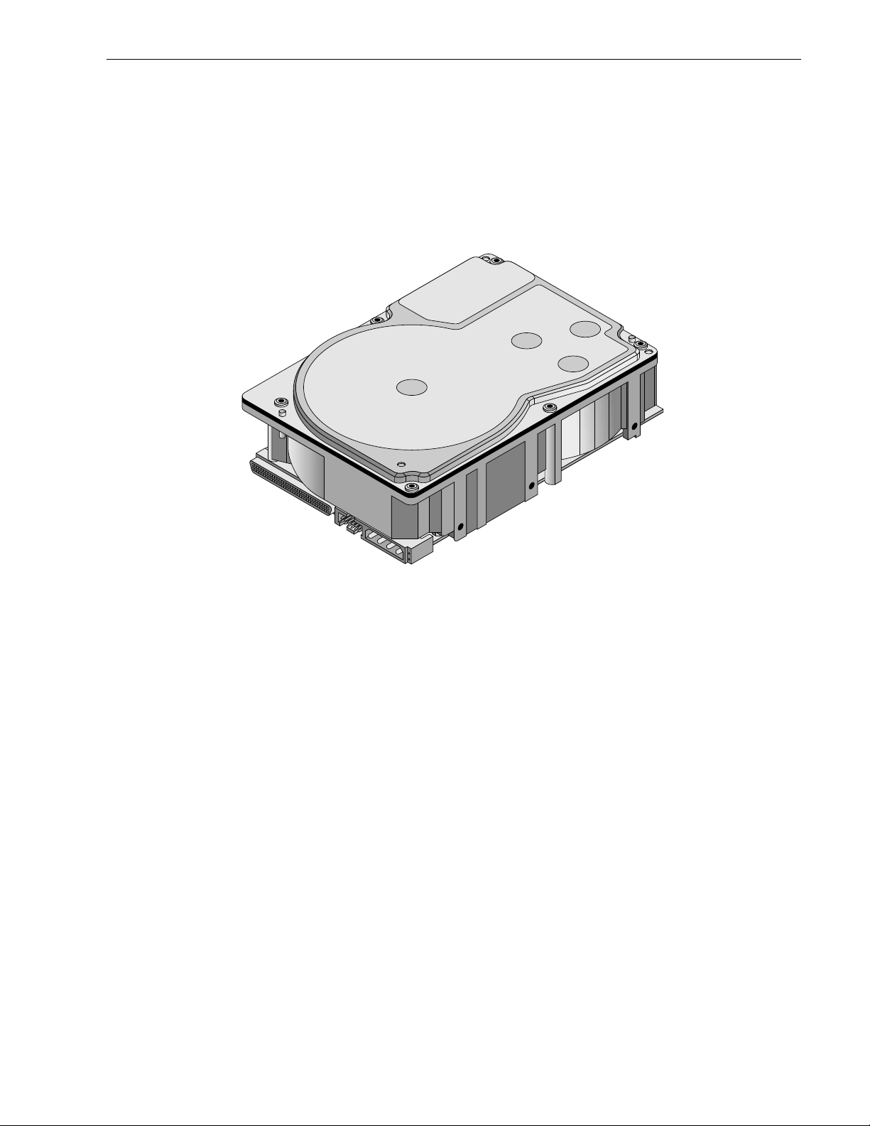
This manual describes the Seagate Technology®, LLC , Barracuda 36™ disc drives.
Barracuda 36 drives support the small computer system interface (SCSI) as described in the ANSI SCSI,
SCSI-2, and SCSI-3 ( Fast-20 and Fast-40) interface specific ations to the extent descr ibed in this manual. T he
SCSI Interface Product Manual (pa rt number 7773847 9) describes general SC SI interface characteristics o f
this and other families of Seagate drives.
From this point on in this produc t manual the reference to Barracud a 36 models is referred to as “the dr ive”
(unless references to individual models are necessary).
*
*Model “LW” version with 68 pin SCSI I/O connector
Figure 1. Barracuda 36 family drive
Page 12

Page 13

Barracuda 36 Product Manual, Rev. C 3
2.0 Applicable standards and reference documentation
The drive has been developed as a system peripheral to the highest standards of design and construction. The
drive depends upon i ts host equip ment to provide adequ ate power and environment i n order to achieve optimum performance and compli ance with applicable industry and governm ental regulations. Special attention
must be given in the areas of safety, power distribution, shielding, audible noise control, and temperature regulation. In particular, the drive must be secur e ly mo unte d i n o rd er to guara ntee the s pec if ied per for ma nc e char acteristics. Mounting by bottom holes must meet the requirements of Section 8.4.
2.1 Standards
The Barracuda 36 family compli es with S eaga te s tan dar ds a s n oted in the appropriate se cti ons o f thi s Manual
and the Seagate SCSI Interface Product Manual, part number 77738479 (Vol. 2).
The Barracuda 36 disc drive is a UL recognized component per UL1950, CSA certified to CAN/CSA C22.2 No.
950-95, and VDE certified to VDE 0805 and EN60950.
2.1.1 Electromagnetic compatibility
The drive, as delivered, is designed for system integration and installation into a suitable enclosure prior to use.
As such the drive is suppli ed as a subassembly and is not su bject to Subpar t B of Part 15 of the FCC Rules
and Regulations nor the Radio Interference Regulations of the Canadian Department of Communications.
The design characteristics of the drive serve to minimize radiation when installed in an enclosure that provides
reasonable shielding. As such, the drive is capable of meeting the Class B limits of the FCC Rules and Regulations of the Canadian Department of Communications when properly packaged. However, it is the user’s
responsibility to assure that the drive meets the appropriate EMI req uirements in their syst em. Shielded I/O
cables may be required if the e nclosure does not provide ad equate sh ielding. If the I/O c ables are externa l to
the enclosure, shielded cables should be used, with the shields grounded to the enclosure and to the host controller.
2.1.2 Electromagnetic susceptibility
As a component assembly, the drive is not required to meet any susceptibility per formance requ irements. It is
the responsibility of tho se integrating the dr ive within their sy stem s to perform thos e tests req uired and design
their system to ensu re that equipment operating in the sam e system as the drive or external to the s ystem
does not adversely affect the performance of the drive. See Section 5.1.1 and T able 2, DC power requirements.
2.2 Electromagnetic compliance
Seagate uses an independ ent laboratory to co nfirm compliance to the directives/standard(s) for CE Mark ing
and C-Tick Marking. The drive was tested in a representative system for typical applications. The selected system represents the most popular characteristics for test platforms. The system configurations include:
• typical current use microprocessor
• 3.5-inch floppy disc drive
• Keyboard
• Monitor/display
• Printer
• External modem
• Mouse
Although the test system wi th this Seag ate mode l co mpl ie s to the dire cti ves/standa rd(s ), we cann ot gua rante e
that all systems will comply. The computer manufacturer or system i ntegrator shall confir m EMC complianc e
and provide CE Marking and C-Tick Marking for their product.
Electromagnetic compliance for the European Union
If this model has the CE Marki ng it complies with the European Union requirem ents of the Electromagnetic
Compatibility Direc tive 89/336/EEC o f 03 May 1989 as ame nded by Direct ive 92/31/EE C of 28 Ap r il 1992 an d
Directive 93/68/EEC of 22 July 1993.
Page 14

4 Barracuda 36 Product Manual, Rev. C
Australian C-Tick
If this model has the C-Tick Markin g it complies with the Australia/New Zea land Standard A S/NZS3548 199 5
and meets the Electro magnetic Compatibility (EMC) Framework requirements of Australia’s Spectrum Management Agency (SMA).
2.3 Reference documents
Barracuda 36 Installation Guide Seagate P/N 77767529
SCSI Interface Product Manual Seagate P/N 77738479
ANSI small computer system interface (SCSI) document numbers:
X3.131-1994 SCSI-2
T10/1302D SPI-3
X3T10/1143D EPI
SFF-8046 Specification for 80-pin connector for SCSI disk drives
SCA-2 EIA Specification ANSI/EIA
Package Test Specification Seagate P/N 30190-001 (under 100 lb.)
Package Test Specification Seagate P/N 30191-001 (over 100 lb.)
Specification, Acoustic Test Requirements, and Procedures Seagate P/N 30553-001
In case of conflict between this document and any referenced document, this document takes precedence.
Page 15

Barracuda 36 Product Manual, Rev. C 5
3.0 General description
Barracuda 36 drives combine magnetoresistive (MR) heads, partial response/maximum likelihood (PRML)
read channel electronics, embedded servo technology , and a SCSI-3 (Fast-20 and Fast-40) interface to provide
high performance, high capaci ty data storage for a variety of syste ms incl uding en ginee ring work statio ns, network servers, mainframes, and supercomputers.
Fast-20 and Fast-40 (also known as Ultra-1 SCSI and Ultra-2 SCSI, respectively) are negotiated transfer rates.
These transfer rates will occur only if your host adapter als o supports these dat a t ransfer rates. This drive also
operates at SCSI-1 and SCSI-2 data transfer rates for backward compatibility with non-Fast-20/Fast-40 capable SCSI host adapters.
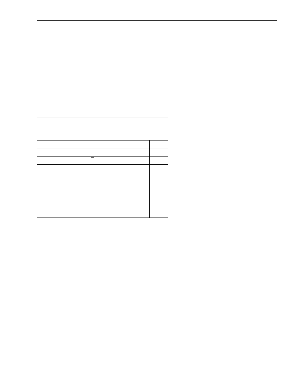
Table 1 lists the features that differentiate the various Barracuda 36 models.
Table 1: Drive model number vs. differentiating features
Model number
Number
of heads I/O circuit type [1]
Number of I/O
connector pins
Number of I/O
data bus bits
ST136475LW 20 multimode (SE/LVD) 68 16
ST136475LC 20 multimode (SE/LVD) 80 16
[1] See Section 9.6 for details and definitions.
The drive records and recovers data on 3.5-inch (86 mm) non-removeable discs.
The drive suppor ts the Small Computer System Interface (SCSI) as descr ibed in the ANSI SCSI-2/SCSI-3
SPI-2 interface specifications to the extent described in this manual (volume 1), which defines the product performance character is ti cs of th e Barracuda 36 family of drives, and the SCSI Inter face Produc t Manual (volume
2), part number 77738479, whi ch describes the general interface characteri stics of this and other families of
Seagate SCSI drives.
The drive’s interface supports multiple initiators, disconnect/reconnect, self-configuring host software, and
automatic features that relieve the host from the necessity of knowing the physical characteristics of the targets
(logical block addressing is used).
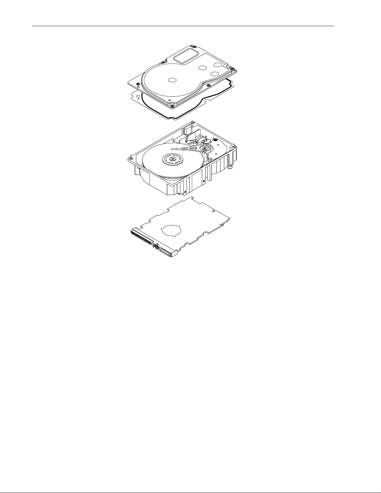
The head and disc assembly (HDA) is sealed at the factory. Air circulates within the HDA through a nonreplaceable filter to maintain a contamination-free HDA environment.
Refer to Figure 2 for an exploded view of the drive. This exploded view is for information only—never disa ssemble the HDA and do not attempt to service items in the seal ed enclo sure (h eads, med ia, actuat or, etc.) as this
requires special facilities. The drive contains no replaceable parts. Opening the HDA voids your warranty.
Barracuda 36 dri ves use a dedic ated landing zone at the innermost radius of the med ia t o el imi na te th e pos s ibility of destroying or degrading da ta by landing in the d ata zone. The drive automa tically goes to the landing
zone when power is removed.
An automatic shipping lock prevents potential damage to the heads and discs that results from movement during shipping and ha ndl ing . T he shi ppi ng lock au toma tic al ly di se nga ges whe n power is applied to the drive and
the head load process begins.
Barracuda 36 drives decode track 0 locatio n data from the servo data embedded on each surface to eliminat e
mechanical transducer adjustments and related reliability concerns.
A high-performance actuator assembly with a low-inertia, balanced, patented, straight-arm design provides
excellent performance with minimal power dissipation.
Page 16
6 Barracuda 36 Product Manual, Rev. C
Figure 2. Barracuda 36 family drive
Page 17

Barracuda 36 Product Manual, Rev. C 7
3.1 Standard features
The Barracuda 36 family has the following standard features:
• Integrated SCSI controller
• Multimode SCSI single-ended or low voltage differential drivers and receivers
• 16 bit I/O data bus
• Asynchronous and synchronous data transfer protocol
• Firmware downloadable via SCSI interface
• Selectable sector sizes from 512 to 2,048 bytes/sector in multiples of 2 bytes/sector
• Programmable drive capacity
• Programmable sector reallocation scheme
• Flawed sector reallocation at format time
• Programmable auto write and read reallocation
• Reallocation of defects on command (post format)
• Enhanced ECC correction capability up to 185 bits
• Sealed head and disc assembly
• No preventative maintenance or adjustment required
• Dedicated laser textured head landing zone
• Embedded servo data rather than a separate servo data surface
• Self diagnostics performed when power is applied to the drive
• 1:1 Interleave
• Zoned bit recording (ZBR)
• Vertical, horizontal, or top down mounting
• Dynamic spindle brake
• 1 Mbyte, or optional 4 Mbyte data buffer
• Hot plug compatibility (section 9.6.4.2 lists proper host connector needed) for “LC” model drives
• SCAM (SCSI Configured AutoMagically) plug-n-play level 2 compliant, factory set to level 1 (not user select-
able)
• Low audible noise for office environment
• Low power consumption
3.2 Media characteristics
The media used on the dr ive has a di ameter of a pproximately 3 .5 in ches (8 6 mm). The alumi num substrat e is
coated with a thin film magneti c mat eria l, overcoated with a propr iet ar y prote ctive layer for improved durability
and environmental protection.
3.3 Performance
• Suppor ts industry standard Fast-20 and Fast-40 SCSI inter faces (also called “Ultra-1 SCSI” and “Ultra-2
SCSI,” respectively)
• Programmable multi-segmentable cache buffer (see Section 4.4)
• 7200 RPM spindle. Average latency = 4.17 ms
• Command queuing of up to 64 commands
• Background processing of queue
• Supports start and stop commands (spindle stops spinning)
3.4 Reliability
• 1,000,000 hour MTBF
• LSI circuitry
• Balanced low mass rotary voice coil actuator
• Incorporates industry-standard Self-Monitoring, Analysis and Reporting Technology (S.M.A.R.T.)
• Incorporates Seek To Improve Reliability algorithm (STIR)
• 5-year warranty
Page 18

8 Barracuda 36 Product Manual, Rev. C
3.5 Unformatted and formatted capacities
Formatted capacity depends on the number of spare reallocation sectors reserved and the number of bytes per
sector. The following table shows the standar d OEM model rea d capacities da ta. Total LBAs = read cap acity
data shown below +1.
Formatted capacity
data block size 512 bytes/sector [1]
ST136475 43D671Fh (36 GB) [2]
Notes.
[1] Sector size se lectable at format time. Users having the necessar y equipmen t may modify the data block
size before issuing a format co mmand and obtain different formatted capa cities than those listed. See
Mode Select Command and Format Command in the SCSI Interface Product Manual, part number
77738479.
[2] User available capacity depends on spa re reallocation scheme se lected. The number of data tracks per
sparing zone and the number of alte rnate sectors (LBAs ) per sparing zone can be deter mined by using
the Mode Sense command and reading Mode Page 03h. Total LBAs(h) x 200(h) = total byte capacity.
3.6 Programmable drive capacity
Using the Mode Select co mmand, the drive can change its capacity to so mething less than maximum. See
Table 5.2.1-13 in the SCSI Interface Product Manual, part number 77738479. Refer to the Parameter list block
descriptor number of blocks field. A value of zero in the number of blocks field indicates tha t the drive shall not
change the capaci ty it is currently formatted to have. A number in the numb er of blocks field that is les s than
the maximum number of LBAs chang es the total dri ve capacity to the value in the block descriptor number of
blocks field. A value of FF FF FF FF in t he number of blocks fiel d restores th e dri ve capacity t o the maxi mum
capacity.
3.7 Factory installed accessories
OEM Standard dr ives are shipped with t he Barracuda 36 Installati on Guide, part number 7776752 9 (unless
otherwise specified ). The factory also ships wi th the drive a small bag of jumper plug s us ed for the J2, J5, an d
J6 option select jumper headers.
3.8 Options (factory instal led)
All customer request ed options are incorporate d during production or packaged at the manufacturin g facility
before shipping. Some of the options available are (not an exhaustive list of possible options):
• Other capacities can be ordered depending on sparing scheme and sector size requested.
• 4 Mbyte optional buffer size.
• Single unit shipping pack. The drive is norm ally shipped in bulk pa ckaging to provide maximum protec tion
against transit damage. Units shipped individually require additional protection as provided by the single unit
shipping pack. Users planning single unit distribution should specify this option.
• The Barracuda 36 Installation Guide, part number 77767529, is included with each standard OEM dr ive
shipped, but extra copies may be ordered.
3.9 Accessories (user installed)
The following accessories are available. All accessories may be installed in the field.
• Single unit shipping pack.
Page 19

Barracuda 36 Product Manual, Rev. C 9
4.0 Performance characteristics
4.1 Internal drive characteristics (transparent to user)
ST136475
Drive capacity 36.4 GByte (formatted, rounded off values)
Read/write heads 20
Bytes/track 186 Kbytes (average, rounded off values)
Bytes/surface 2184 Mbytes (unformatted, rounded off values)
Tracks/surface (total) 11,721 Tracks (user accessible)
Tracks/inch 12,580 TPI
Peak bits/inch 223 KBPI
Internal data rate 137-240 Mbits/sec (variable with zone)
Disc rotational speed 7,200 r/min
Average rotational latency 4.17 msec
Recording code 16/17 EPR4
4.2 SCSI performance characteristics (visible to user)*
The values given in Section 4.2 .1 apply to all mo dels of the Barracuda 3 6 family unless otherwis e specified.
Refer to Section 9.10 and to the SC SI Interface Product Manual, part number 777384 79, for addition al timin g
details.
4.2.1 Access time [8]
Including controller overhead
(without disconnect) [1] [4]
Drive level
Read Write
msec
Average – Typical [3] 7.6 8.4
Single Track – Typical [3] 0.9 1.2
Full Stroke – Typical [3] 16 17
4.2.2 Format command execution time (minutes) [1]*
ST136475
Maximum (with verify) 80
Maximum (no verify) 40
4.2.3 Generalized performance characteristics
Minimum sector interleave 1 to 1
Data buffer transfer rate to/from disc media (one 512-byte sector):
Min. [4]*
Avg. [4]
Max. [4]
16.2
25.3
28.3
MByte/sec
MByte/sec
MByte/sec
Data buffer transfer rate to/from disc media: (< 1 track):
Min. [4]
Avg. [4]
Max. [4]
MByte/sec divided by (interleave factor)
12.2
MByte/sec divided by (interleave factor)
18.8
MByte/sec divided by (interleave factor)
21.2
*[ ] All notes for Section 4.2 are listed at end of Section 4.2.3.
Page 20

10 Barracuda 36 Product Manual, Rev. C
SCSI interface data transfer rate (asynchronous) [5]:
Maximum instantaneous 3.5 Mbytes/sec [6]
Maximum average 3.5 Mbytes/sec [7]
Synchronous transfer rate for SCSI Fast-20 (Ultra-1 SCSI):
16 bit data bus models 40 Mbytes/sec
Synchronous transfer rate for SCSI Fast-40 (Ultra-2 SCSI):
16 bit data bus models 80 Mbytes/sec
Synchronous transfer rate for fast SCSI-2:
16 bit data bus models 20 Mbytes/sec
Sector Sizes:
Default 512 byte user data blocks
Variable 512 to 2,048 bytes per sector in multiples of 2
bytes per sector.
If n (number of bytes per sector requested) is
odd, then n-1 sectors will be used.
Read/write consecutive sectors on a track Yes
Flaw reallocation performance impact (for flaws reallocated at format time using
the spare sectors per sparing region reallocation scheme.)
Overhead time for one track cylinder switch in sequential mod 1.1 msec (typical)
Average rotational latency 4.17 msec
Notes for Section 4.2.
[1] Execution time measur ed from receipt of the last Byte of the Co mmand Descriptor Block (CDB) to the
request for a Status Byte Tr ansfer to the Initiator (excluding connect/disconnect).
[2] Maximum times are specified over the worst case conditions of te mperature, voltage margins and drive
orientation. W hen co mpar ing spec ified a ccess times, ca re sh ould be taken to dis tingui sh bet ween typic al
access times and maximum acc ess times. The b est compar ison is o btained by syst em benchmar k tests
conducted under identical conditions. Maximum times do not include error recovery.
[3] Typical Access tim es are measu red u nder nomina l con ditio ns of temperatur e, voltage, and hor izonta l or i-
entation as measured on a representative sample of drives.
[4] Assumes no errors and no sector has been relocated.
[5] Rate measured from the start of the first sector transfer to or from the Host.
[6] Assumes system ability to support the rates listed and no cable loss.
[7] Simulated.
[8] Access time = controller overhead + average seek time
Access to data = controller overhead + average seek time + latency time
4.3 Start/stop time
After DC power at no minal voltage h as been appl ied, the d r ive becom es rea dy withi n 30 sec onds if the Mo tor
Start Opti on is disabled (i.e. the motor star ts as soon as the power has bee n applied). If a recoverable error
condition is detected during the start sequence, the drive executes a recovery procedure which may cause the
time to become rea dy to exceed 30 seconds. Dur ing spin up to ready time the dr ive responds to s ome commands over the SCSI interface in less than 1.5 seconds afte r application of power. Stop time is less than 20
seconds from removal of DC power.
Negligible
If the Motor Star t Option is en abled, the inter nal cont roller accep ts the comm ands lis ted in the SCSI Interface
Product Manual less than 3 seconds aft er DC power has been appli ed. After the Motor Start Co mmand has
been received the d rive becomes ready for nor mal opera tions withi n 13 seco nds typic ally (excluding an error
recovery procedure). The Mo tor Start Comm and can also be used to comm and the drive to stop the spindle
(see SCSI Interface Product Manual, 77738479).
There is no power control switch on the drive.
Page 21

Barracuda 36 Product Manual, Rev. C 11
4.4 Prefetch/multi-segmented cache control
The drive provides prefetch (read look-ahead) and multi-segmented cache control algorithms that in many
cases can enhance system performance. “Cache” as used herein refers to the drive buffer storage space when
it is used in “cache” operations. To select prefetch and cache features the host sends the Mod e Select command with the proper values in the app licable bytes in Mode Page 08h (see SCSI Interface Product Manual
77738479). Prefetch and cache operation are inde pendent features from the st andpoint that ea ch is enabled
and disabled independently via th e Mode Select comm and. However, in actual operation the prefetch feature
overlaps cache operation somewhat as is noted in Section 4.5.1 and 4.5.2.
All default cache and prefetch Mode pa rameter values (Mode Page 08h) for standard OEM versions of this
drive family are given in Table 9.
4.5 Cache operation
In general, all but 100 Kbytes of the physical buffer space in the drive can be used as st orage sp ace for cach e
operations. The buffer can be divided int o logi cal segm ent s (Mode Selec t Page 08h, byte 13) from which dat a
is read and to which data is wr itten. T he dr ive maintains a table of log ical block disk medium addr esses of th e
data stored in each segment of the buffer. If cache operation is enabled (RCD bit = 0 in Mode Page 08h, byte 2,
bit 0. See SCSI Interface Prod uct Manual, part numb er 77738479), data requested by the host with a Read
command is retrieved from the buffer (if it is there), before any disc access is initiated. If cache operation is not
enabled, the buffer (still segmented with required numb er of segments ) is still use d, but only as circula r buffer
segments during d isc medium read op erations (disregard ing Prefetch operation for the moment) . That is, the
drive does not check in the buffer segments for the requested read data, but goes di rectly to the medium to
retrieve it. The retrieved data merely passes thr ou gh some buffer segment on the way to the host. On a cache
“miss”, all data transfers to the host are in accordance with “buffer-full” ratio rules. On a cache “hit” the drive
ignores the “buffer-full” ratio rules. See explanations associated with Mode page 02h (disc onnect/reconnect
control) in the SCSI Interface Product Manual.
The following is a simplified description of a read operation with cache operation enabled:
Case A -
1. Drive transf ers to the initiator the first LB requested plus all subsequent contiguous LB’s that are alrea dy in
2. When a requested LB is re ached th at is not i n any c ache segm ent, th e dr ive fetches it a nd any r emai ning
3. If the prefetch feature is enabled, refer to Section 4.5.2 for operation from this point.
Case B -
1. The drive fetches the requested LB’s from the disc and transfers them into a segment, an d from there to
2. If the prefetch feature is enabled, refer to Section 4.5.2 for operation from this point.
Each buffer segment is actually a s elf-contained circular storage (wrap-around oc curs), the le ngth of which is
an integer number of disc medium sectors. The wrap-around capability of the individual segments greatly
enhances the buffer’s over all performance as a cache storage, allowing a wide range of user selectable configurations, which includes their use in the prefetch operation (if enabled), even when cache operation is disabled
(see Section 4.5.2). The number of se gments may be sele cted using th e Mode Sel ect comma nd, but the size
can not be direct ly s elec ted. S ize is s elec ted onl y as a by-produc t of selec ting the s egment number speci fication. The size in Kbytes of each segment is not reported by the Mode Sense command page 08h, bytes 14 and
15. The value 0XFFFF is always reported. If a size specification is sent b y the host in a Mode Sele ct comma nd
(bytes 14 and 15) no new segment size is set up by the d rive, and if the “STRICT” bit in Mode page 00h (byte
2, bit 1) is set to one, the dr ive responds as it does for any attempt to change unc hangeable parameters (see
SCSI I/O Product Manual 77738479). The dr ive supports operation of any intege r number of segm ents from 1
to 16.
A Read command is received and the first logical block (LB) is already in cache:
the cache. This data may be in multiple segments.
requested LBs from the disc an d puts them in a s egment of the cache. The dr ive transfers the remainin g
requested LBs from the ca che to t he host in accorda nce with the disconn ect/r econn ect speci fication mentioned above.
A Read command requests data, the first LB of which is not in any segment of the cache:
the host in accordance with the disconnect/reconnect specification referred to in case A.
Page 22

12 Barracuda 36 Product Manual, Rev. C
4.5.1 Caching write data
Write caching is a wr ite op eration by the dr ive that makes use of a drive buffer storage area where the data t o
be written to the medium is stored in one or more segments while the drive performs the write command.
If read caching is enabled (RCD=0), then data written to the medium is retained in the cache to be made available for future read cache hits. The s ame buffer space and segme ntat ion is u sed a s set up for read func tions.
The buffer segmentation scheme is set up or changed independently, having nothing to do with the s tate of
RCD. When a write comma nd is issued, if RCD=0 , the cache is first checked to see if any logical blocks that
are to be writte n are already stored in the cach e from a previous read or write comman d. If there are, the
respective cache segments are cleared. The new data is cached for subsequent Read commands.
If the number of wri te data lo gical blocks exceeds t he size of t he segme nt being w ritte n into, when the end o f
the segment is reached, the data is written into the beginning of the same cache segment, overwriting the data
that was written there at the beginning of the operation. Howev er, the drive does not overwrite data that has not
yet been written to the medium.
If write caching is enabled (WCE=1), then the drive may return GOOD status on a write command after the
data has been transferred into the cache, but before the data has been written to the medium. If an error occurs
while writing the data to the medium, and GOOD status has already been returned, a deferred error will be
generated. Write commands that have returned GOOD status but still have uncommitted data in the cache are
treated similarly to a normal queued command and therefore occupy a command queue slot. This may termporarily reduce the number of commands that may be queued by the host until the write data has been written to
the medium.
The Synchronize Cache command may be used to force the drive to write all cached write data to the medium.
Upon completion of a Synchronize Cache command, all data received from previous write commands will have
been written to the medium. The Star t/Stop command with the stop bit s et will force a sync cache operat ion
before the drive stops.
Table 9 shows Mode default settings for the drives.
4.5.2 Prefetch operation
If the Prefetch feature is enabled, data in conti guous lo gical blocks on the disc i mmedia tely b eyond that which
was requested by a Read comman d can be retri eved and stored in the buffer for immediate transfer from the
buffer to the host on subsequent Read commands that request those logical blocks (this is true even if “cache”
operation is disabled). Though the pr efetch operation uses the buffer as a “cache”, finding the requested dat a
in the buffer is a prefetch “hit”, not a “cache” operation “hit”. Prefetch is enabled using Mod e Select pa ge 08h,
byte 12, bit 5 (Disable Read Ahe ad - DRA bit). DRA bit = 0 enables prefetch. Since data that is prefetched
replaces data already in some buffer segment(s), the host can lim it the amount of prefetch data to optim ize
system performance. Th e max pre fetch field (bytes 8 and 9) limits th e amount of pr efetch. The dri ve does not
use the prefetch “ceiling” field (bytes 10 and 11).
During a prefetch operation, the dri ve crosses a cyl inder bounda r y to fetch more data o nly if the Discontinuity
(DISC) bit is set to one in bit 4 of byte 2 of Mode parameters page 08h.
Whenever prefetch (read look-ahead) is enabled ( enabled by DRA = 0), it opera tes und er the co ntrol of ARLA
(Adaptive Read Look-Ahead). If the host uses software interleave, ARLA enables prefetch of contiguous blocks
from the disc when it senses that a prefetch “hit” will likely occur, even if two consecutive read operations were
not for physically contiguous blocks of data (e.g. “software interleave”). ARLA disables prefetch when it decides
that a prefetch “hit” will not likely occur. If the host is not using software i nterleave, and if two sequen tial read
operations are not for contiguous blocks of data , ARL A dis ables pre fetch, but as long as s equ enti al read oper ations request contiguous blocks of data, ARLA keeps prefetch enabled.
Page 23

Barracuda 36 Product Manual, Rev. C 13
5.0 Reliability specifications
The following reliability spe cifications assume correct hos t/drive operational interface, including all interface
timings, power supply voltages, environmental requirements and drive mounting constraints (see Section 8.4).
Seek Errors
Less than 10 in 10
Read Error Rates [1]
Recovered Data Less than 10 errors in 10
Unrecovered Data Less than 1 sector in 10
Miscorrected Data Less than 1 sector in 10
MTBF 1,000,000 hours
Service Life 5 years
Preventive Maintenance None required
Note.
[1] Error rate specified with automatic retries and data correction with ECC enabled and all flaws reallocated.
5.1 Error rates
The error rates stated in this specification assume the following:
• The drive is operated per this specification using DC power as defined in this manual (see Section 6.2).
• The drive has been formatted with the SCSI FORMAT commands.
• Errors caused by media d efects or hos t system failures are exclude d from er ror rate comp utat ions. Refer to
Section 3.2, “Media Characteristics.”
8
seeks
12
bits transferred (OEM default settings)
15
bits transferred (OEM default settings)
21
bits transferred
5.1.1 Environmental interference
When evaluating systems operatio n under condit ions of Ele ctromagnetic Interference (EMI), the performanc e
of the drive within the s ystem shall b e consi dered acce ptable if the dr ive does not g enerate an unre coverable
condition.
An unrecoverable error, or unrecoverable condition, is defined as one that:
• Is not detected and corrected by the drive itself;
• Is not capable of being detected from the error or fault status provided through the drive or SCSI interface; or
• Is not capable of being recovered by normal dr ive or sys tem rec overy pro cedur es wit hou t opera tor inte rven-
tion.
5.1.2 Read errors
Before determination or measurement of read error rates:
• The data that is to be used for measurement of read error rates must be verified as being written correctly on
the media.
• All media defect induced errors must be excluded from error rate calculations.
5.1.3 Write errors
Write errors can occur as a result of media defects, environmental interference, or equipment malfunction.
Therefore, write errors are not predictable as a function of the number of bits passed.
If an unrecoverable write error occurs beca use of a n equipm ent mal functi on in the dr ive, the error is classi fied
as a failure affecting MTBF. Unrecoverable write errors are those which cannot be corrected within two
attempts at writing the record with a read verify after each attempt (excluding media defects).
Page 24

14 Barracuda 36 Product Manual, Rev. C
5.1.4 Seek errors
A seek error is de fin ed as a failure o f t he drive to position the h eads to t he add re ss ed track. Th ere shall be no
8
more than ten recoverable seek errors in 10
physical seek operations. After detecting an init ia l se ek err or, the
drive automatically p erforms an error rec overy process. If the error recovery process fails, a seek pos itioning
error (15h) is repor ted wit h a Medium err or (3h) or Har dware error (4h) repo rt ed in the Sense Key. This is an
unrecoverable seek error. Unrecoverable seek errors are classified as failures for MTBF calculatio ns. Refer to
the SCSI Inte rface Product Manual, par t number 777384 79, for Request Sense information. Se e also Appendix A of this manual for a list of sense keys and additional sense codes supported by this drive.
5.2 Reliability and service
You ca n en hance the reli abili ty of B arracuda 36 di sc dr ives by ensur ing that the dr ive receives adequa te coo ling. Section 6.0 pr ovides tempe rature me asurements and othe r information that may be used to en hance th e
service life of the drive. Section 8.3.1 provides recommended air-flow information.
5.2.1 Mean time between failure
The production d isc drive shall achieve an MTBF o f 1,000,000 hours when operated in an environment that
ensures the case temperatures specified in Section 6.4.1, Table 3, Column 2 are not exceeded. Shor t-term
excursions up to the specification limits of the operating environment will not affect MTBF performance. Continual or sustained operation at cas e temperatures above the values shown in Table 3, Column 2 may degrade
product reliability.
The following expression defines MTBF
Estimated power-on operating hours in the per i od
MTBF per measurement period =
Number of drive failures in the period
Estimated power-on operation hours means power-up hours per disc drive times the total number of disc drives
in servic e. Each dis c dr ive shal l have accumulated a t leas t nine month s of o peration. Data sha ll be calc ulated
on a rolling average base for a minimum period of six months.
Drive failure means any stoppage or substandard performance caused by drive malfunction.
5.2.2 Preventive maintenance
No routine scheduled preventive maintenance shall be required.
5.2.3 Service life
The drive shall have a useful ser vic e life of five years. Depot repair or repl aceme nt of maj or parts is per m itted
during the lifetime (see Section 5.2.4).
5.2.4 Service philosophy
Special equipmen t is requir ed to repair the drive HDA. In order to achi eve the above service life, repairs must
be performed only at a proper ly equip ped and staffed ser vice and repair facility. Troubleshooting and r epair of
printed circuit board assemblies (PCBAs) in the field is not recommended, because of the extensive diagnostic
equipment required for effective servicing. Also, there are no spare parts available for this drive. Drive warranty
is voided if the HDA is opened.
5.2.5 Service tools
No special tools are requi red for site instal lat ion or recomm ended for site maintenance. Refer to Section 5.2.4.
The depot repair philosophy of the drive precludes the necessity for special tools. Field repair of the drive is not
practical since there are no user purchasable parts in the drive.
Page 25

Barracuda 36 Product Manual, Rev. C 15
5.2.6 Hot plugging Barracuda 36 disc drives
The ANSI SPI-2 (T10 /1142D) documen t defines the physical requi rements for removal and inser tion of SCS I
devices on the SCSI bus. Four cases are addressed. The cases are differentiated by the state of the SCSI bus
when the removal or insertion occurs.
Case 1 All bus devices powered off during removal or insertion
Case 2 RST signal asserted continuously during removal or insertion
Case 3 Current I/O processes not allowed during insertion or removal
Case 4 Current I/O process allowed during insertion or removal, except on the device being changed
Seagate Barracuda disc drives support all four hot plugging cases. Provision shall be made by the system such
that a device being inser ted ma kes power and ground connecti ons prior to the connection of any device signal
contact to the bus. A device being rem oved shall mai nta in p ower and gr oun d c onn ect ion s after th e d isco nne ction of any device signal contact from the bus (see SFF-8046, SCA-2 specification).
It is the responsibility of the systems integrator to assure that no hazards from temperature, energy, voltage, or
ESD potential are presented during the hot connect/disconnect operation.
All I/O processe s for the SCSI device bein g inser ted or removed shall b e quiescent. A ll SCSI devices on th e
bus shall have receivers that conform to the SPI-2 standard.
If the device being hot plugged uses single-ended (SE) drivers and the bus is currently operating in low voltage
differential (LVD) mode, then all I/O processes for all devices on the bus must be completed , and the bus quiesced, before attempting to hot plug. Following the insertion of the newly installed device, the SCSI host
adapter must issue a Bus Res et, followed by a synchronous transfer negotiation. Failure to perform the SCSI
Bus Reset could result in erroneous bus operations.
The SCSI bus termination and termination power source shall be external to the device being inserted or
removed.
End users should not mix devices with high voltage differential (H VD) drivers and receivers and devices wit h
SE, LVD, or multimode drivers and receivers on the s ame SCSI bus since the commo n mode voltages in the
HVD environment may not be controlled to safe levels for SE and LVD devices (see ANSI SPI-2).
The disc drive spindle must co me to a complete st op prior to comple tely removing the dr ive from the cabinet
chassis. Use of the Stop Spin dle co mmand o r partial with drawal of the drive, enough to be disc onnec ted fro m
the power source, prior to removal are methods for insuring that this requirement is met. During drive insertion,
care should be taken to avoid exceeding the limits stated in Section 6 .4.4, "S hock and vibration," of this manual.
5.2.7 S.M.A.R.T.
S.M.A.R.T. is an acronym for Self-Monitori ng Analys is and Rep or ting Technology. This technology is intended
to recognize conditions that indi cate a dri ve failure and is designed to provide suffic ient war ning of a failure to
allow data back-up before an actual failure occurs.
Note.
Each attribute ha s bee n s el ec ted to mo nit or a sp ec ifi c s et of failure conditions in the op erati ng pe rforma nc e o f
the drive, and the thresholds are optimized to minimize “false” and “failed” predictions.
Controlling S.M.A.R.T.
The operating mode of S.M.A.R.T. is controlled by the DEXCPT bit and the PERF bi t of the “Informational
Exceptions Control Mo de Page” (1Ch). The DEXCPT bit is us ed to enable or disable the S.M.A.R.T. process.
Setting the DEXCPT bit will disable all S.M.A.R.T. functions. When enabled, S.M.A.R.T. will collect on-line data
as the drive performs nor m al re ad/wr ite operatio ns. When t he PER F bit is set, th e dr ive is consi dered to be in
“On-line Mode Only” and will not perform off-line functions.
The firmware will monitor specific attributes for degradation over time but cannot predict instantaneous
drive failures.
The process of measuri ng off-line attributes and saving data can be forced by the RTZ (return to zero) command. Forcing S.M.A.R.T. will reset the timer so that the next scheduled interrupt will be two hours.
Page 26

16 Barracuda 36 Product Manual, Rev. C
The drive can be interrogated by the host to determine the time remaining before the next scheduled measurement and data loggi ng process will oc cur. This is accomplished by a log sense command to log page 0x3E .
The purpose is to allow the customer to control when S.M.A.R.T. interruptions occur. As described above, forcing S.M.A.R.T by the RTZ command will reset the timer.
Performance impact
S.M.A.R.T. attribute data will be saved to the disc for the purpose of recreating the events that caused a predictive failure. The drive will measure and save parameters once every two hours subject to an idle per iod on the
SCSI bus. The process of m easuring off-line attr ibute data and saving data to th e disc is u ninterrup table and
the maximum delay is summarized below:
Maximum processing delay
On-line only delay Fully enabled delay
DEXCPT = 0, PERF = 1 DEXCPT = 0, PERF = 0
S.M.A.R.T. delay times 65 milliseconds 490 milliseconds
Reporting control
Reporting is controlled in the “Informational Exceptions Contro l Page” (1Ch). Subj ect to the reporting method ,
the firmware will issue to the “host” an 01-5D00 sense code. The error code is preser ved through bus resets
and power cycles.
Determining rate
S.M.A.R.T. monitors the rate at which errors occur and s ignals a pred ictive failure if the rate of degraded er ror
rate increases to an una cc ept able level. To determine rate, error events are logged and compared to the number of total operations for a given attr ibute. The inter val defines the number of operations over which to m easure the rate. The counter that keeps track of the c urrent number of operations is referred to as the I nterval
Counter.
S.M.A.R.T. measures error rate, hence for each attribute the occurr ence of an “error” is recorded. A counter
keeps track of the number of errors for the current interval. This counter is referred to as the Failure Counter.
Error rate is simply the number of errors per ope ration. The algorithm that S.M.A.R.T. uses to record rates of
error is to set thresholds for the number of errors and the interval. If the number of errors exceeds the threshold
before the interval expires, then the error rate is cons idered to be u nacceptable. If the numbe r of errors d oes
not exceed the threshold before the interval expires, then the error rate is considered to be acceptable. In either
case, the interval and failure counters are reset and the process starts over.
Predictive failures
S.M.A.R.T. signals predictive failures when the drive is performing unaccep tably for a period o f time. The f ir mware keeps a running count of the number of times the error rate for each attribute is unacceptable. To accomplish this, a counte r is incremen ted whenever the error rate is una cceptable and de cremented ( not to exceed
zero) whenever the error rate is acceptable. Should the counter continually be incremented such that it reaches
the predictive threshold, a predictive failure is signaled. This counter is referred to as the Failure History
Counter. There is a separate Failure History Counter for each attribute.
5.2.8 Product warranty
Beginning on the date of shipment to customer and continuing for a period of five years, Seagate warrants that
each product (including components and subassemblies) or spare part that fails to function properly under normal use due to defect in mater ials on work mans hip or du e to nonc onform ance t o the app lica ble specific ations
will be repaired or replaced, at Seagate’s option and at no charge to custom er, if returned by customer at customer’s expense to Seagate’s designated facility in accordance wi th Seagate’s Warranty Procedure. Seagate
will pay for transporting th e repair or replacement item to customer. For more detailed warranty information
refer to the Standard terms and conditions of Purchase for Seagate products.
Page 27

Barracuda 36 Product Manual, Rev. C 17
Shipping
When transpor ting or shipping a dr ive, a Seagate approved container must be used. Keep your origina l box.
They are easily identifi ed by the Seagate Approved Package label. Shipping a dr ive in a non-approved container voids the drive warranty.
Seagate repair centers may refuse receip t of compon ents imp roper ly pa ckaged or obviously damaged in transit. Contact your Authorized Seaga te Dis tr ibutor to pur chase addition al boxes. Seagate recommends ship ping
by an air-ride carrier experienced in handling computer equipment.
Product repair and return information
Seagate customer se rvice centers are the only facilities author ized to service Seagate drives. Seagate does
not sanction any third-par ty repair facilities. Any unauthorized repai r or tampering with the factory- seal voids
the warranty.
Page 28

Page 29
Barracuda 36 Product Manual, Rev. C 19
6.0 Physical/electrical specifications
This section p rovides informat ion relating to the physical and el ectrical characteristics of the Barracuda 36
drive.
6.1 AC power requirements
None.
6.2 DC power requirements
The voltage and current requirements for a single drive are shown in the following table. V alues indicated apply
at the drive power connector. The single ended power requirements i ncludes the inter nal disc dr ive SCSI I/O
terminatio n. The table shows current values in Amperes. See also Figure 3c for current and power values vs.
number of I/O operations.
Table 2: DC power requirements
ST136475
LC/LW
Notes
Voltage +5 V +12 V
Regulation [5] ±5% ±5%[2]
Average idle current DCX
[1] 0.75 0.8
Maximum starting current
(peak DC) DC
(peak AC) AC
[3]
[3]
Delayed motor start (max) DC [1][4] 0.65 0.03
Peak operating current
Typical DCX
Maximum DC
[1][6]
[1]
Maximum (Peak)
LVD
1.05 2.8
4.2
1.05
1.4
1.7
1.3
1.5
3.15
[1] Measured wi th average reading DC ammeter. Instantaneous +12 V curr ent peaks will exceed thes e val-
ues. Power supply is at nominal voltages.
[2] For +1 2 V, a –10% droop is permissible during initial start of spindle, and must return to ±5% before 7,200
rpm is reached. T he ±5% must be maintained after the drive signifies that its power-up seque nce has
been completed and that the drive is able to accept selection by the host initiator.
[3] See +12 V current profile in Figu re 3a.
[4] This co ndition occurs when the Mo tor Star t Opti on is enabled an d the dr ive has not yet received a Star t
Motor command.
[5] See Section 6.2.1 “Conducted Noise Immunity.” Specified voltage tolerance i s inclusive of ripple, noise,
and transient response.
[6] Operating condition is defined as random 8 block reads at 160.5 input/output operations per second. Cur-
rent and power specified at nom inal voltages. Increasing +5 V su pply by +5% increases 5 V cur rent by
4.62%. Decreasing +12 V supply by 5% increases +12 V current by 18.75%.
General Notes from Table 2:
1. Minimum current loading for each supply voltage is not less than 4% of the maximum operat ing current
shown.
2. The +5 and +12 volt supplies shall employ separate ground returns.
3. Where power is provided to multiple drives from a common supply, careful consideration for individual drive
power requirements should be noted. Where multiple units are powered on simultaneously, the peak starting current must be available to each device.
Page 30

20 Barracuda 36 Product Manual, Rev. C
6.2.1 Conducted noise immunity
Noise is specified as a periodi c and random distribution of frequencie s covering a band from DC to 10 MHz.
Maximum allowed noise values given below are peak to peak measurements and apply at the drive power connector.
+5 V = 150 mV pp from 0 to 50 kHz and 100 mV pp from 50 kHz to 10 MHz.
+12 V = 150 mV pp from 0 to 50 kHz and 100 mV pp from 50 kHz to 10 MHz.
6.2.2 Power sequencing
The drive does not requir e power sequencing. T he drive protects aga inst inadver tent wr iting dur ing power-up
and down. Daisy-chain operation re quires tha t power be mai ntained on the ter min ated dr ive to ensur e proper
termination of the peripheral I/O ca bles. To au tomatically delay motor star t based on th e target ID (SCSI ID)
enable the Delay Motor Start op tion and disable the Ena ble Motor Star t opti on on the J2 con nector. See Section 8.1 for pin selection inform ation. To delay the motor until the drive receives a Start Unit comma nd, enable
the Enable Motor Start option on the J2 connector.
6.2.3 Current profile
Figures 3a and 3b i dentif y the d r ive +5 V and + 12 V c urrent profi le. The curr ent dur i ng the various t imes is as
shown:
T - Power is applied to the drive.
T1 - Controller self tests are performed.
T2 - Spindle begins to accelerate under current limiting after performing drive internal
diagnostics. See Note 1 of Table 2.
T3 - The heads move from the landing zone to the data area.
T4 - The adaptive servo calibration sequence is performed.
T5 - Calibration is complete and the drive is ready for reading and writing.
Note.
All times and currents are typical. See Table 2 for maximum current requirements.
4.0
3.5
+12V
Current
(amps)
3.0
2.5
2.0
1.5
1.0
0.5
0.0
T1
T2
T
AC
Component
Nominal (average) DC curve
T4
T3
T5
0.0 4 8 12 20 24 28 32 40
Figure 3a. Typical Barracuda 36 family drive +12 V current profile
16 36
TIME (seconds)
Page 31

Barracuda 36 Product Manual, Rev. C 21
1.4
1.2
AC
Component
Nominal (average) DC curve
T4T1
T3
16 36
TIME (seconds)
+5V
Current
(amps)
1.0
0.8
0.6
0.4
0.2
0.0
T2
T
0.0 4 8 12 20 24 28 32 40
Figure 3b. Typical Barracuda 36 family drive +5 V current profile
T5
Page 32

22 Barracuda 36 Product Manual, Rev. C
6.3 Power dissipation
To obtain drive typical operating random read (8 blocks) power dissipation at nominal voltages, refer to Figures
3c and 3d. The dr ive user can d e cide for themse lves what number of I/O operations consti tute s a ty pica l number of I/O operations for their installatio n. Multiply Watts times 3.4123 to obtai n BTUs per hour. Typical power
dissipation under idle conditions is 13.35 Watts (45.55 BTU per hour).
1.2
1.0
0.8
0.6
Amperes
0.4
0.2
0
0204060
Figure 3c. DC current and power vs. input/output operations per second (LVD only)
1.2
1.0
80 100 120
I/Os per Second
140 160
24
20
16
12
24
20
5V A
12V A
Watts
Watts
8
4
0
5V A
12V A
Watts
0.8
0.6
Amperes
0.4
0.2
0
0204060
Figure 3d. DC current and power vs. input/output operations per second (SE only)
80 100 120
I/Os per Second
140 160
16
12
Watts
8
4
0
6.4 Environmental limits
Temperature and humidity values experienced by the d rive must be such that cond ens ation does not occur on
any drive part. A ltitude and atmospher ic pressure specificat ions are referenced to a standa rd day at 58.7°F
(14.8°C). Maximum Wet Bulb temperature is 82°F (28°C).
6.4.1 Temperature
a. Operating
With cooling designed to ma intain the ca se temperatur es of Table 3, Column 2, the drive meets all specifications over a 41°F to 122°F (5°C to 50°C) drive ambient temperature range with a maximum temperat ure
Page 33

Barracuda 36 Product Manual, Rev. C 23
gradient of 36°F (20°C) per hour. The enclosu re for the drive should b e designed such that the temperatures at the locations sp ecified in Table 3, column 1 are not exceede d. Air flow may be needed to achieve
these temperature values (see Section 8. 3 and 8.3.1 ). Ope rati on at cas e tem pera tures [4] ab ove these values may adversely affect the drives ability to meet specifications.
The MTBF specification for the drive is based on operating in an environment th at ensures that the case
temperatures specified in Table 3, column 2 are not exceeded. Occasional excursions to drive ambient temperatures of 122°F (50°C) or 41°F (5°C) may occur withou t impact to specified MTBF. Air flow may be
needed to achieve these temperatures (see Se ction 8.3.1). Continual o r sustained operati on at case temperatures above these values may degrade MTBF.
To confirm that the required cooling for the Barracuda electronics and HDA is provided, place the drive in its
final mechanical configuration, perform random write/read operations. After the temperatures stabilize,
measure the case temperature of the components listed in Table 3 (see notes [2] and [3]).
Operation of the drive at the maximum case temperature is intended for short time periods only. Continuous
operation at the elevated temperatures will reduce product reliability.
Table 3: PCBA (Printed Circuit Board Assembly) and HDA temperatures
Items in
Figure 4
Column 1
Maximum case [4]
temperatures (°C)
operating (50° ambient) [2]
Column 2
Maximum allowable
case [4] temperatures (°C)
to meet MTBF spec.
HDA [3] 60 45
U2 (read channel) 110 90
U5 (SCSI controller) 118 98
U11 (servo demod) 105 85
U15 (servo ASIC 100 80
Note.
[1] Section 8.3.1 describes the air-flow patter ns to be used to meet case temperatu res in column 2. Air
flow should be opposite that shown in Section 8.3.1. Air velocity should be adequate to ensure that the
case temperatures in Column 2 are not exceeded during drive operation.
[2] The temperatures in Column 1 are calculated and may not reflect actual operating values. Sufficient
cooling air may be required to ensure that these values are not exceeded.
[3] Measure HDA temp at point labeled “HDA” on Figure 4.
[4] PCBA mounted integrated circuit case.
b. Non-operating
–40° to 158°F (–40° to 70°C) package ambient w ith a maximum gradient of 45°F (25°C) per hour. This
specification assumes that the drive is packaged in the shipping container designed by Seagate for use with
drive.
Page 34

24 Barracuda 36 Product Manual, Rev. C
HDA Temp.
Check Point
.5"
Model “LW” PCBA [1]
U8
U15
U11
U16
U18
U19
J5 J1
PCBA 2
U2
U5
Model “LC” PCBA [1]
U8
J4
U15
U11
U16
U18
U19
J1
J4
U2
U4U4
U5
PCBA 3
[1] Bottom side of PCBA
Figure 4. Locations of PCBA components listed in Table 3
Page 35

Barracuda 36 Product Manual, Rev. C 25
6.4.2 Relative humidity
The values below assume that no condensation on the drive occurs.
a. Operating
5% to 95% non-condensing relative humidity with a maximum gradient of 10% per hour.
b. Non-operating
5% to 95% non-condensing relative humidity.
6.4.3 Effective altitude (sea level)
a. Operating
–1,000 to +10,000 feet (–305 to +3,048 meters)
b. Non-operating
–1,000 to +40,000 feet (–305 to +12,210 meters)
6.4.4 Shock and vibration
Shock and vibration limits spec ified in this docume nt are mea sured di rectl y on the dr ive chass is. If the dr ive is
installed in a n enclosu re to whic h the stat ed shock and/o r vibratio n crit eria is applied, resonance s may occur
internally to the enclosure resulting in drive movement in excess of the stated limits. If this situation is apparent,
it may be necessary to modify the enclosure to minimize drive movement.
The limits of sho ck and vibration de fined within this document are speci fied with the drive mounted by any of
the four methods shown in Figure 5, and in ac cordance with the restriction s of Section 8.4 . Orientation of th e
side nearest the LED may be up or down.
6.4.4.1 Shock
a. Operating—normal
The drive, as installed for normal operation, shall operate error free while subjected to intermittent shock not
exceeding 5 Gs at a max imum duration of 11 msec (hal f s in ewave). Shock may be applied in the X , Y, or Z
axis.
b. Operating—abnormal
Equipment, as installed for normal operation, does not incur physical damage while subjected to inter mittent shock not exceeding 10 Gs at a maximum duration of 11 msec ( half sinewave). Shock occurring a t
abnormal levels may promote degraded operational performance during the abnormal shock period. Specified operational performance will continue when normal operating shock levels resume. Shock may be
applied in the X, Y, or Z axis. Shock is not to be repeated more than two times per second.
c. Non-operating
The limits of non- operating shock shal l appl y to all cond itions of h andlin g and transportation. This inc ludes
both isolated drives and integrated drives.
The drive subjected to nonrepeti tive shock not exceeding 50 Gs at a maximum duration of 11 msec (half
sinewave) shall not exhibit device damage or performan ce degradati on. Shock may be appl ied in the X, Y,
or Z axis.
The drive subjected to nonrepeti tive shock not exceeding 135 Gs at a maximum duration of 2 msec (half
sinewave) does not exhibit device damage or performance degradation. Sh ock may be applied in the X , Y,
or Z axis.
Page 36

26 Barracuda 36 Product Manual, Rev. C
d. Packaged
Disc drives shipped as lo ose load ( not pall etized) general fr eight will b e packaged to withs tand drop s from
heights as defined in the table below. For additional details refer to Seagate specifications 30190-001
(under 100 lbs/45 kg) or 30191-001 (over 100 lbs/45 Kg).
Package size Packaged/product weight Drop height
<600 cu in (<9,800 cu cm) Any 60 in (1524 mm)
600-1800 cu in (9,800-19,700 cu cm) 0-20 lb (0 to 9.1 kg) 48 in (1219 mm)
>1800 cu in (>19,700 cu cm) 0-20 lb (0 to 9.1 kg) 42 in (1067 mm)
>600 cu in (>9,800 cu cm) 20-40 lb (9.1 to 18.1 kg) 36 in (914 mm)
Z
Y
X
Figure 5. Recommended moun ting
X
Z
Y
Page 37

Barracuda 36 Product Manual, Rev. C 27
6.4.4.2 Vibration
a. Operating - normal
The drive as installed for normal operation, shall comply with the complete specified performance whil e
subjected to continuous vibration not exceeding
5-22 Hz @ 0.02 inches (0.51 mm) displacement peak to peak
22-350 Hz @ 0.5 G 0 to peak
Vibration may be applied in the X, Y, or Z axis.
b. Operating - abnormal
5-22 Hz @ 0.03 inches (0.76 mm) displacement peak to peak
22-350 Hz @ 0.75 G (X, Y, or Z axis) 0 to peak
c. Non-operating
The limits of non-operating vibration shall apply to all conditions of handling and transportation. This
includes both isolated drives and integrated drives.
The drive shall not incur physical dama ge or degraded performan ce as a resu lt of continuous vi bration not
exceeding
5-22 Hz @ 0.081 inches (2.05 mm) displacement peak to peak
22-350 Hz @ 2.00 G 0 to peak
Vibration may be applied in the X, Y, or Z axis.
6.4.5 Air cleanliness
The drive is designed to operate in a typical office environment with minimal environmental control.
6.4.6 Acoustics
Sound power during idle mode shall be 4.2 bels typical when measured to Seagate’s 30553-001 specification.
6.4.7 Electromagnetic susceptibility
See Section 2.1.2.
Page 38

28 Barracuda 36 Product Manual, Rev. C
6.5 Mechanical specifications
The following table lists nominal dimensions for the drive. Refer to Figures 6a and 6b for detailed mounting configuration dimensions. See Section 8.4, “Dr ive mounting.”
Height: 1.62 in 41.1 mm
Width: 4.000 in 101.6 mm
Depth: 5.75 in 146.05 mm
Weight: 2.2 pounds .99 kilograms
C
[3]
G
K
H
[2]
M [6]
[6] N
S [8]
[1]
E
B
J
J2
J6 LED
P [5]
R
A
[4] L
D
F
Notes:
[1]
Mounting holes three on each side, 6-32 UNC. Max
screw length into side of drive 0.15 in. (3.81 mm). Screw tightening
torque 6.0 in-lb (.675 NM) max with minimum thread engagement of
0.12 in. (3.05 mm).
[2]
Mounting holes four on bottom, 6-32 UNC. Max screw length into
bottom of drive 0.15 in. (3.81 mm). Screw tightening torque 6.0 in-lb
(.675 NM) max with minimum thread engagement of 0.12 in. (3.05 mm).
[3]
Power and interface connectors can extend past the “A” dimension
by 0.040 in. (1.02 mm).
[4]
Centerline of pad for Pin 1 of power connector.
[5]
Centerline of pad for Pin 1 of J6.
[6]
Centerline of pad for Pin 1 of J2. Dimensions indicated are for
reference only.
[7]
Dimensions to Pin 1 of each connector are nominal values.
[8]
To pin ends on J6. Pin ends on J6 are nominally
flush with end of drive.
Dimension Table
Inches
A
5.75
4.00
1.620
2.362
1.120
4.000
.250
1.750
3.750
1.625
.143
.753
.165
.405
2.265
2.350
± .025
± .015
+ .027
– .021
± .010
± .020
± .010
+ .010
– .005
± .010
± .010
± .020
[7] [7]
B
C
D
E
F
G
H
J
K
L
M
N
P
R
S
Millimeters
146.05
101.60
41.1
60.00
28.45
101.60
6.35
44.45
95.25
41.28
3.63
19.13
4.19
10.29
52.53
59.69
± .64
± .25
+ .69
– .53
± .25
± .51
± .25
+ .25
– .12
± .25
± .25
± .51
Figure 6a. Mounting configuration dimensions for “LW” model
Page 39

Barracuda 36 Product Manual, Rev. C 29
C
[3]
G
[7]
XN
H
[13] K
[1]
E
L
Pin 1
Connector Centerline
M [5]
[2]
U [9]
J2
[9] T
S [11]
J6 LED
P [8]
D
F
A
Notes:
Notes:
Mounting holes three on each side, 6-32 UNC. Max screw length
[1]
into side of drive 0.15 in. (3.81 mm). Screw tightening torque 6.0
in-lb (.675 NM) max with minimum thread engagement of 0.12 in.
(3.05 mm).
Mounting holes four on bottom, 6-32 UNC. Max screw length into
[2]
bottom of drive 0.15 in. (3.81 mm). Screw tightening torque 6.0
in-lb (.675 NM) max with minimum thread engagement of 0.12 in.
(3.05 mm).
Interface connector is flush with the end of drive within
[5]
B
[7]
X
J
R
[3]
±0.020 in. (.5 mm). The interface connector location may extend
beyond HDA dimension “A” by 0.020 in. (.5 mm).
Connector J1 is centered (side to side) on drive within ±0.020 in.
[4]
(.508 mm).
Dimension “M” is from bottom rear drive mounting holes center(s)
[5]
to the face of the connector at the center of the drive.
Dimensions “M” and “N” are unique requirements for SCA drives
[6]
only, required for conformance with latest SFF Spec #8337.
Maximum connector non-perpendicularity to side planes pointed
[7]
to by X.
Centerline of pad for Pin 1 of J6.
[8]
Centerline of pad for Pin 1 of J2. Dimensions indicated are for
[9]
reference only.
Dimensions to Pin 1 of each connector are nominal values.
[10]
To pin ends on J6. Pin ends on J6 are nominally flush with end of drive.
[11]
Nominal values cannot be added to any toleranced dimension to
[12]
achieve a valid toleranced dimension.
Dimension “K” is from drive mounting hold to end of drive chassis
[13]
(not the PCBA).
Dimension Table
Millimeters
146.05
101.60
41.1
60.00
28.45
101.60
6.35
44.45
95.25
60.45
4.597
41.28
.38
10.29
52.53
59.69
4.19
19.13
± .64
± .38
+ .69
– .53
± .25
± .51
± .25
+ .25
– .12
± .25
± .25
± .25
+ .38
– .25
± .50
[6]
[7]
Inches
5.75
A
B
C
D
E
F
G
H
J
K
L
M
N
P
R
S
T
U
± .025
4.00
± .015
1.620
+ .027
– .021
2.362
± .010
1.120
± .020
4.000
± .010
.250
+ .010
– .005
1.750
± .010
3.750
± .010
2.380
± .010
0.181
+ .015
– .010
1.625
± .02
.015
.405
2.265
2.350
[10] [10]
.165
.753
Figure 6b. Mounting configuration dimensions for “LC” model
Page 40

Page 41

Barracuda 36 Product Manual, Rev. C 31
7.0 Defect and error management
The drive, as delivered, complies with this specification. The read error rate and specified storage capacity are
not dependent upon use of defect management routines by the host (initiator).
Defect and error management in the SC SI system involves the drive internal de fect/error management an d
SCSI systems error consid erations (e rrors in co mmunica tions between Initiat or and the dr ive). Tools for use in
designing a defect/error management plan are briefly ou tli ned in this se ctio n, wi th r eferences to othe r sec ti ons
where further details are given.
7.1 Drive internal defects
During the initial d rive format operati on at the factor y, media defects are identified, tagged as being unusa ble,
and their locations rec orded on the drive primar y defects list (referred to as the “P” li st and also as the EFT
defect list). At factory format time, these known defects are also reallocat ed, that is, reassigned to a new place
on the medium and the l ocation listed in the defects reallocation table. The “P” li st is not alter ed after factory
formatting. Locations of defects found and reallocated d uring error r ecovery procedures after drive shipment
are listed in the “G” l ist (defects growth list). Th e “P” and “G” lists may be referenced by the initiator using the
Read Defect Data command (refer to the SCSI Interface Product Manual, part number 77738479).
7.2 Drive error recovery procedures
Whenever an error occurs during dr ive operation, the drive, if programmed to do so, performs error recovery
procedures to attempt to recover the data. The error recovery procedures used de pend on the option s previously set up in the error recovery pa rame ters m ode page. Erro r rec overy and de fect manageme nt may involve
the use of several SCSI commands, the details of which ar e descr ibed in t he SCSI Inte rface Product Manual .
The drive implements selectable error recovery time limits such as are required in video applications. For additional information on th is, refer to the Error Re covery Page table in the SCSI Interface Product Manual , which
describes the Mode Sele ct/ Mod e Sens e Erro r Recovery param ete rs.
The error recovery scheme supported by the drive provides a means to control the total error recovery time for
the entire command in addition to controlling the recovery level for a single LBA. The total amount of time spent
in error recovery for a command can be l im ite d via the Rec overy Tim e L im it bytes in the Error Recovery Mode
Page. The total amount of time spent in error recovery for a single LBA can be limited via the Read Retry Count
or Write Retry Count bytes in the Error Recovery Mode Page.
The drive firmware error recovery algorithms consist of 12 levels for read recoveries and 16 levels for writes.
Table 4 equates the Read and Write Retry Count with the m aximum pos sible recover y time for read and wr it e
recovery of individual LBAs. The times given do not include time taken to perform reallocations, if reallocations
are performed. Reallocations are performed when the ARRE bit (for reads) or AWRE bit (for writes) is one, the
RC bit is zero, and the Recovery Time Limit for the command has not yet been met. Time nee ded to perform
reallocation is not counted against the Recovery Time Limit.
The Read Continuous (RC) bit, wh en set to one, re quests t he disc drive to transfer the requ ested data length
without adding del ays (for retries or E CC correction) that may be required to insure data integrit y. T he disc
drive may send erroneous data in order to maintain th e continuous flow of data. The RC bit should only be
used when data integrity is not a concern and speed is of utmost impor tance. If the Recovery Time Limit or
retry count is rea ched dur ing err or recovery, the state of the RC bit is examined. If th e RC bit is set, the dr ive
will transfer the unrecovered data with no error indication and cont inue to execute the remaining command. If
the RC bit is not set, the dr ive will stop data transfer with the last good LBA, and repor t a “CHECK CONDITION, UNRECOVERED READ ERROR.”
Page 42

32 Barracuda 36 Product Manual, Rev. C
Table 4: Read and write retry count maximum recovery times [1]
Read retry
count
0 108.68 0 91.96
1 125.4 1 117.04
2 426.36 2 125.4
3 459.8 3 150.48
4 526.68 4 300.96
5 593.56 5 359.48
6 677.16 6 593.56
7 802.56 7 618.64
8 836 8 660.44
9 911.24 9 685.52
10 2371.24 10 1735.68
11 (default) 3422.04 11 1760.76
Maximum reco very time per
LBA (cumulative, msec)
Write retry
count
12 1769.12
13 1794.2
14 1944.68
15 2003.2
Maximum reco very time per
LBA (cumul ativ e, msec)
[1] These values may change at any time. They are presently for general information only.
Setting these retr y counts to a value below the default setting could result in an incre ased unrecovered error
rate which may exceed the value given in this product manual. A setting of zero results in the drive not performing error recovery.
For example, suppose the read/write recovery page has the RC bit = 0, the read retry count set to four, and the
recovery time limit (Mode Sense Page 01, bytes 10, 11) is set to FF FF hex (maximum). A four LBA read command is allowed to take up to 526.68 msec recovery time for each of the four LBAs in the comm and. If the
recovery time limit (M ode Sense Page 01, bytes 10, 11) is set to 00 C8 hex (200 milliseco nds deci mal) a four
LBA read command is al lowed to take up to 200 millisec onds for all error recover y within that co mmand. The
use of the recovery time limit field (Mode Sense Page 01, bytes 10,11) allows finer granularity on control of the
time spent in error recovery. The Recovery Time Limit only starts counting when the drive is executing error
recovery and it resta rts on each c ommand. Therefore, each command’s total recovery tim e is subject to the
Recovery Time Limit. Note: A RTL of zero (0) will use the drive default value of FF FF. Minimum RTL is
achieved by specifying the RTL set to 00 01.
7.3 SCSI systems errors
Information on the repor ting of ope rational errors or faults across t he interface is given in the SCSI Interface
Product Manual, part number 77738479. Message Protocol System is described in the SCSI Interface Product
Manual. Several of the messages are used in the SCSI systems error management system. The Request
Sense command re turns i nformation t o the host abou t numerous kin ds of errors or faults. The Receive Diagnostic Results reports the results of diagnostic operations performed by the drive.
Status returned by the drive to the Initiator is described in the SCSI Interface Product Manual. Status reporting
plays a role in the SCSI sys tems e rror m anagem ent and its use i n that r espe ct is desc rib ed in s ections wher e
the various commands are discussed.
Page 43

Barracuda 36 Product Manual, Rev. C 33
8.0 Installation
The first thing to do when installi ng a drive is to set the drive ID (select) on the SCSI bus and set up ce rtain
operating options. This is usually done by installing small shorting jumpers on the pins of connectors J2 and J6
on the prin ted ci rcui t bo ar d a ssembly (PCB A ) (or J5 on the “LW” m ode l) , or via the drive to host I/O signals on
the “LC” model. Some users connect cables to J6 or J5 and perform the set-up using remote switches.
If your system is “SCAM” (SCSI Configured Auto Magically) compliant, the system assigns the drive ID over the
interface, so there is no need to be concern ed about drive ID. Setting the drive ID jumpers doesn’t hur t anything, but is not necessary.
If your system is not “SCAM” compliant you do need to set the drive ID using the ID jumpers.
Configure drive options
For option jumper locations and definitions refer to Figures 7a, 7b, and 7c. Dri ve default mode parameters are
not normally needed for installation. Refer to Section 9.3.2 for default mode parameters if they are needed.
• Ensure that the SCSI ID of the drive is not the same as the host adapter. Most host adapters use SCSI ID 7.
ID 7 is the highest priority on both 8 and 16 bit data buses.
• If multiple devices are on the bus set the drive SCSI ID to one that is not presently used by other devices on
the bus.
• If the drive is the only device on the bus, attach it to the end of the SCSI bus cable. External terminators must
be provided by the user, systems integrator or host equipment manufacturer.
• If the drive is attached to a bus that conta ins other devices, and th e new drive is not a ttached to t he end of
the bus, no terminator is required on the new drive.
Note.
• Set all appropriate option jumpers for desired operation prior to power on. If jumpers are changed after
• Installation instr uc ti ons ar e pr ovided by host syste m doc um enta tio n or with any additi ona ll y purc has ed drive
• Do not remove the manufacturer’s installed labels from the drive and do not cover with additio nal label s, as
Formatting
• It is not necessar y to low level format this dri ve. The drive is shipped fro m the factory l ow level formatted in
• Reformat the drive if a different spare sector allocation scheme is selected.
• High level format the drive involves assigning on e or more par titions or logical drives to the drive volume.
• Systems that have Windows 95 Operating Sys tem version 950B (this has FAT 3 2) or later do not need to
8.1 Drive ID/option select header
Figures 7a and 7b shows v iews of the drive ID select jumper connec tors. Figure 7c shows the option select
jumper connector for all mode ls. Figur e 7 b sh ows a rea r view of mode l drives for the purpose of sh owing J5 o f
the drive. Both J5 and J6 have pins for selecting drive ID and for connecting the remote LED cable. Only one or
the other should be used, although using both at the same time would not damage the drive. The notes following the figures descr ibe the functions of the various jum per positions on the connec tors J2, J5, and J6. See
your local sales repre sentative for suggested par t number. A bag containing jum per plugs is sh ipped with the
standard OEM drives.
For additional information about terminator requirements, refer to Sections 9.8 and 9.9.
power has been applied, recycle the drive power to make the new settings effective.
installation software. If necessary see Section 10 for Seagate support services telephone numbers.
the manufacturer labels contain information required when servicing the product.
512 byte sectors.
Follow the instructions in the system manuals for the system into which the drive is to be installed.
partition the drive.
Page 44

34 Barracuda 36 Product Manual, Rev. C
Drive
Front
Jumper Plug
(enlarged to
show detail)
Pin 1
J6
R
Reserved
L
E
E
A2A1A
A
S
D
0
3
SCSI ID = 0 (default)
SCSI ID = 1
SCSI ID = 2
SCSI ID = 3
SCSI ID = 4
SCSI ID = 5
SCSI ID = 6
SCSI ID = 7
SCSI ID = 8
SCSI ID = 9
SCSI ID = 10
SCSI ID = 11
SCSI ID = 12
SCSI ID = 13
SCSI ID = 14
SCSI ID = 15
Shipped with cover installed.
Host
Alternate
Usage Plug:
+5V
[1]
Reserved
Pins
1197531
6842
Ground
Do not install jumpers;
retain cover.
Drive Activity LED
Dashed area is optional host circuitry (external to the drive)
connected to host supplied optional usage plug.
Do not connect anything to pins 13-20.
[1] Voltage supplied by drive
Figure 7a. Barracuda 36 family drive ID select for models “LW” and “LC”
Page 45

Barracuda 36 Product Manual, Rev. C 35
Drive HDA (rear view, PCBA facing downward)
68 Pin
SCSI I/O Connector
J1
Pin 1
+5V Ground
Pin 1
Pin 12
SCSI ID = 0 (default)
SCSI ID = 1
SCSI ID = 2
SCSI ID = 3
SCSI ID = 4
SCSI ID = 5
SCSI ID = 6
SCSI ID = 7
SCSI ID = 8
SCSI ID = 9
SCSI ID = 10
SCSI ID = 11
SCSI ID = 12
SCSI ID = 13
SCSI ID = 14
SCSI ID = 15
J5
A3A2A
A
1
0
Host Alternate
Usage Plug
+5V
Ground
Dashed area is optional host circuitry (external to the
drive) connected to host supplied optional usage plug.
1197531
[1]
12 10 8 6 4 2
+5V
N.C.
Drive Activity LED
A0A1A2A
3
1P2P3P4P
J1-DC Power
PCBA
For ID selection use
jumpers as shown or
connect a cable for
remote switching as
shown below.
Pins 1, 3, 5, and 7 are
optional connections to
switching circuits in host
equipment to establish
drive ID.
Remote Switches
Pins 2, 4, 6, and 8 are
normally not grounded.
They are driven low (ground)
for 250 ms after a Reset
or PWR ON to allow drive to
read SCSI ID selected.
[1] Voltage supplied by drive
Figure 7b. Barracuda 36 family drive ID select header J5 for “LW” model (J5 Pins 1–12)
Page 46

36 Barracuda 36 Product Manual, Rev. C
[1]
Jumper
Positions
J2
SEDSMEWPP
D
Pin 1
R
R
E
EST
S
P
Force Single-Ended I/O
Single-Ended or
Low-Voltage Differential
(default)
Delay Motor Start
Enable Motor Start
Write Protect
Parity Disable
Term. Power to SCSI Bus [2]
J2
Jumper Plug
J6
J2
(enlarged to
show detail)
Drive
Front
[1] Jumper position names shown here are not marked on the PCBA. They are shown here for reference only.
Additional notes on these functions in Section 8.1.1.
[2] This option is available on “LW” models only. Additional notes on these functions in Section 8.1.1.
Figure 7c. Barracuda 36 family drive option select header for both “LC” and “LW” models
Page 47

Barracuda 36 Product Manual, Rev. C 37
8.1.1 Function description
J2
jumper
installation Jumper function description
SE
On Forces drive to use single-ended I/O drivers/receivers only.
Off Drive can operate on the interface in low voltage differential mode or single-ende d, depend-
ing on the voltage state of the I/O “DIFFSNS” line.
Default
is no jumper on.
DS ME
Off
Off Spindle starts immediately after power up—
Default
setting.
Off On Drive spindle does not start until Start Unit command received from host.
On Off Spind le Star tup is delayed by SCSI ID times 12 secon ds after power is applied, i. e., drive 0
spindle star ts immed iately when D C power connecte d, drive 1 star ts afte r 12 second delay,
drive 2 starts after 24 second delay, etc.
On On Drive spindl e starts when Start Unit com mand received from host. Delayed star t feature is
overridden and does not apply when ME jumper is installed.
WP
On Entire drive is write protected.
Off
Drive is not write protected.
Default
is no WP jumper installed.
PD
On Parity checking and parity error reporting by the drive is disabled.
Off
Drive checks for parity and reports result of parity checking to host.
Default
is PD jumper not installed.
RES
Off
Reserved jumper position. Default is no jumper installed.
TP
Off
No terminator power is connected to dr ive terminat ors or SCSI bus I/O c able.
Default
is no
jumper on.
On Drive supplies terminator power to SCSI bus I/O cable (see Figure 7c for pins used for Term-
power). A jumper on
TP
position may be needed to power external terminators on “LW” mod-
els (see Section 9.8 and Figure 10). TP not used on “LC” models.
Page 48

38 Barracuda 36 Product Manual, Rev. C
8.2 Drive orientation
The balanced rotary arm actuator design of the drive allows it to be mounted in any orientation. All drive performance characterization, however, has been done with the drive in horizontal (discs level) and vertical (drive on
its side) orientations, and these are the two preferred mounting orientations.
8.3 Cooling
Cabinet cooling must be des igned by th e custo mer so that the ambien t temperatu re immedi ately s urroundin g
the drive will not exceed temperature c onditions specified in Section 6.4.1, “Temperature.” Specific consideration should be given to make sure adequate air circulation is present ar ound the pr in ted circu it board assembly (PCBA) to meet the requirements of Section 6.4.1, “Temperature.”
8.3.1 Air flow
The rack, cabinet, or drawer environment for the Barracuda 36 dr ive must provide heat rem oval from the electronics and head and d isc assem bly (HDA). You should confirm that ad equate heat removal is provided usin g
the temperature measurement guidelines described in Section 6.4.1.
Forced air flow may be required to keep temp eratures at or below the specifi ed cas e tempe ratures of Table 3,
Column 2, in which case th e drive should be or ient ed, or air flow direc ted, so that th e least amo unt of air flow
resistance is created while providing air flow to the electronics and HDA. Also, the shortest possible path
between the air inlet an d exit should be chosen to m inimize the travel length of air heated by the dr ive and
other heat sources within the rack, cabinet, or drawer environment.
If forced air is determi ned to be necessa ry, possible air-flow patterns are shown in F igure 8. The a ir-flow patterns are created by one or more fans, either forcing or drawing air as shown in the illustrations. Conduction,
convection, or other forced air-flow patter ns are acceptable as long as the temperatu re measurement guidelines of Section 6.4.1 are met.
Above unit
Under unit
Note. Air flows in the direction shown (front to back)
or in reverse direction (back to front)
Note. Air flows in the direction shown or
in reverse direction (side to side)
Figure 8. Air flow (suggested)
Above unit
Under unit
Page 49

Barracuda 36 Product Manual, Rev. C 39
8.4 Drive mounting
When mounting the dri ve using the bottom hol es (x-y pl ane in Figu re 5) care must be taken to ensure that th e
drive is not physically distorted due to a stiff non-flat mounting surface. The allowable mounting surface stiffness is 80 lb/in (14.0 N/mm). The following equation and paragraph define the allowable mounting surface stiffness:
F
K
--- 80lb/in (14.0 N/mm)==
x
where ‘k’ represents the mounting surface stiffness (units of lb/in or N/mm), and ‘x’ represents the out-of-plane
mounting surface distor tion (units of inches or millimeter s). The out-of-plane distor tion (‘x’) is determined by
defining a plane with three of the four mounting points fixed and evaluating the out-of-plane deflec tion of the
fourth mounting point when a known force is applied to the fourth point.
Note.
8.5 Grounding
Signal ground (PCBA) and HDA ground are connecte d together in the drive and cannot be separate d by the
user. The equipment in which the drive is moun ted i s co nnec te d dire ct ly to th e HDA and PCBA wi th n o el ectrically isolating shock mounts. If it is desired for the system chassis to not be connected to the HDA/PCBA
ground, the systems integrator or user must provide a nonconductive (electr ically isol ating) method of mou nting the drive in the host equipment.
Increased radiated emissions may result if you do not provide the maximum surface area ground connection
between system ground and drive ground. This is the system designer’s and integrator’s responsibility.
Before mounting the drive in any kind of 3.5-inch to 5.25-inch adapter frame, verify with Seagate Technology that the drive can meet the shock and vibration s pecifications given herein while mounted i n
such an adapter frame. Adap ter frames that are available may not have a mechanical structure capable of mounting the drive so that it can meet the shock and vibration specifications listed in this manual.
Page 50

Page 51

Barracuda 36 Product Manual, Rev. C 41
9.0 Interface requirements
9.1 General description
This section desc ribes in esse ntia lly general terms the in ter face requir eme nts su pported by the Ba rra cud a 36 .
No attempt is made to des cr ibe al l of the m inute d etail s of co nditio ns and const raints t hat must be consi dere d
by designers when designing a sy stem in which this family of dr ives can properly operate. Seag ate declares
that the drives operate in accordance with the appropriate ANSI Standards referenced in various places herein,
with exceptions as noted herein or in the Seagate SCSI Interface Produc t Manual , part number 77738479.
9.2 SCSI interface messages supported
Table 5 lists the messages supported by the SCSI-2 and SCSI-3 modes of the Barracuda 36 family drives.
Table 5: SCSI messages supported by Barracuda 36 family drives
Supported by
Message nam e Message code
Abort 06h Y
Abort-tag 0Dh Y
Bus device reset 0Ch Y
Clear queue 0Eh Y
Command complete 00h Y
Continue I/O process 12h Y
Disconnect 04h Y
Extended messages 01h[1] Y
Identify 80h-FFh Y
Ignore wide residue (two bytes) 23h Y
Initiate recovery 0Fh N
Initiator detected error 05h Y
Linked command complete 0Ah Y
Linked command complete with flag 0Bh Y
Message parity error 09h Y
Message reject 07h Y
Modify data pointer [1] N
No operation 08h Y
Queue tag messages (two bytes)
Head of queue tag 21h Y
Ordered queue tag 22h Y
Simple queue tag 20h Y
Release recovery 10h N
Restore pointers 03 h Y
Save data pointer 02h Y
Synchronous data transfer req. [1] Y
Target transfer disable 13h Y
Terminate I/O process 11h N
Wide data transfer request [1] Y
SCSI-2/3
Notes.
[1] Extended messages (see the SCSI Interface Product Manual, part number 77738479).
Page 52

42 Barracuda 36 Product Manual, Rev. C
9.3 SCSI interface commands suppor ted
Table 6 following lists the SCSI interface commands that a re suppor ted in the SC SI-2, and SCSI-3 m odes of
the drive. Barracuda 36 Family drives can be changed back and forth between SCSI-1 and SC SI-2/SCSI-3
modes using the Change Definit ion Command. OEM standard drives are shipped set to operate in SCSI-2/
SCSI-3 mode.
Table 6: Commands supported by Barracuda 36 family drive
Command name
Command
code
Supported by
SCSI-2/3
Change definition 40h Y
Compare 39h N
Copy 18h N
Copy and verify 3Ah N
Format unit [1] 04h Y
Block Format N
Bytes from index Y
Physical sector format Y
DPRY bit supported N
DCRT bit supported Y
STPF bit supported Y
IP bit supported Y
DSP bit supported Y
IMMED bit supported Y
VS (vendor specific) N
Inquiry 12h Y
Date code page (C1h) Y
Device Behavior page (C3h) Y
Firmware numbers page (C0h) Y
Implemented operating def page (81h) Y
Jumper settings page (C2h) Y
Supported Vital product data page (00h) Y
Unit serial number page (80h) Y
Lock-unlock cache 36h N
Log select 4Ch Y
DU bit N
DS bit Y
TSD bit Y
ETC bit N
TMC bit N
LP bit N
Log sense 4Dh Y
Cache statistics page (37h) Y
Non-medium error page (06h) Y
Pages supported list (00h) Y
Power-on time page (3Eh) Y
Read error counter page (03h) Y
S.M.A.R.T. status log page (2Fh) Y
S.M.A.R.T. attribute log page (30h) Y
Verify error counter page (0 5h) Y
Write error counter page (02h) Y
Mode select (same pages as Mode Sense command) 15h Y [2]
Page 53

Barracuda 36 Product Manual, Rev. C 43
Table 6: Commands supported by Barracuda 36 family drive (Continued)
Command name
Command
code
Supported by
SCSI-2/3
Mode select (10) 55h Y
Capacity Programming Y
Mode sense 1Ah Y [2]
Caching parameters page (08h) Y
Control mode page (0Ah) Y
Disconnect/reconnect (02h) (DTDC, DIMM not used) Y
Error recovery page (01h) Y
Format page (03h) Y
Information exceptions control page (1Ch) Y
Notch and Partition Page (0Ch) N
Power condition page (1Ah) Y
Rigid disc drive geometry page (04h) Y
Unit attention page (00h) Y
Verify error recovery page (07h) Y
Xor Control page (10h) N
Mode sense (10) 5Ah Y
Prefetch 34h N
Read (10) 28h Y
Read (12) A8h N
Read buffer (modes 0, 2, 3 supported) 3Ch Y
Read capac ity 25h Y
Read defect data (10) 37h Y
Read defect data (12) B7h Y
Read extended 28h Y
DPO bit supported Y
FUA bit supported Y
Read long 3Eh Y
Reassign blocks 07h Y
Rebuild 81h N
Receive diagnostic results 1Ch Y
Supported diagnostics pages (00h) Y
Translate page (40h) Y
Regenerate 82h N
Release 17h Y
Release (10) 57h Y
Request sense 03h Y
Actual retry count bytes Y
Deferred error supported Y
Extended sense Y
Field pointer bytes Y
Reserve 16h Y
3rd party reserve Y
Extent reservation N
Reserve (10) 56h Y
3rd part reserve Y
Extent reservation N
Rezero unit 01h Y
Page 54

44 Barracuda 36 Product Manual, Rev. C
Table 6: Commands supported by Barracuda 36 family drive (Continued)
Command
Command name
code
Search data equal 31h N
Search data high 30h N
Search data low 32h N
Seek 0Bh Y
Seek extended 2Bh Y
Send diagnostics 1Dh Y
Supported diagnostics pages (00h) Y
Translate page (40h) Y
Set limits 33h N
Start unit/stop unit (spindle ceases rotating) (1Bh) 1Bh Y
Synchronize cache 35h Y
Test unit ready 00h Y
Verify 2Fh Y
DPO bit supported Y
BYTCHK bit supported Y
Write 0Ah Y
Write and verify 2Eh Y
DPO bit supported Y
BYTCHK bit supported Y
Write buffer (modes 0, 2, supported) 3Bh Y
Firmware download option (modes 5, 7 supported) [3] Y
Write extended 2Ah Y
DPO bit supported Y
FUA bit support Y
Write long 3Fh Y
Write same 41h Y
XDRead 52h N
XDWrite 50h N
XDWrite extended 80h N
XPWrite 51h N
Supported by
SCSI-2/3
[1] The drive can format to any sector size from 512 to 2,048 bytes/sector in multiples of 2 bytes/sector.
[2] Table 9 shows how individual bits are set and which are changeable by the host.
WARNING:
[3]
A power loss during fl as h programm in g c an re sul t in firmware corruption. This usua ll y m akes
the drive inoperable.
Page 55

Barracuda 36 Product Manual, Rev. C 45
Table 7 lists the Standard Inquiry command data that the drive should return to the initiator per the format given
in the SCSI Interface Product Manual, part number 77738479.
Table 7: Barracuda 36 family drive Standard Inquiry data
Bytes Data (HEX)
0-15 00 00 [02]1[02]28B 00 01 1E 53 45 41 47 41 54 45 20 VENDOR ID
16-31 53 54 [31] [33] [36] [34] [37] [35] [4C] [57]320 20 20 20 20 20 PRODUCT ID
32-47 R# R# R# R# S# S# S# S# S# S# S# S# 00 00 00 00
48-63 000000 0000000000 0000000000000000
64-79 00 00 00 00 00 00 00 00 00 00 00 00 00 00 00 00
80-95 00 00 00 00 00 00 00 00 00 00 00 00 00 00 00 00
96-111 00 43 6F 70 79 72 69 67 68 74 20 28 63 29 20 [31] COPYRIGHT
4
112-127 [39] [39] [39]
128-143 72 69 67 68 74 73 20 72 65 73 65 72 76 65 64 20
1
[]
01 means SCSI-1 implemented;
20 53 65 61 67 61 74 65 20 41 6C 6C 20 NOTICE
02 means SCSI-2/SCSI-3 implemented. Default is 02.
2
[]
01 means response data in SCSI-1 format and has compatibility with Common Command Set data.
02 means response data in SCSI-2/SCSI-3 format. In addition, 12 indicates that the drive uses the hierarchial addressing mode to assign LUNs to logical units. Default is 12.
R# Four ASCII digits represen ting the product Firm ware Version number. The Firmware Release number is
also given in the Vital Product Data page C0h, together with servo RAM and ROM release numbers.
S# Eight ASCII digits representing the eight digits of the product serial number.
3
[]
Bytes 18 through 25 reflect model of drive. Shown here are hex values for Model ST136475LW.
The hex values for bytes 24 and 25 for the various models are listed below.
LW LC
4C 57 4C 43
4
[]
Copyright Year - changes with actual year.
9.3.1 Inquiry Vital Product data
Instead of the standard Inquiry dat a shown in Table 7, the initiator can request several Vital Product Data
pages by setting the Inquir y command EVPD bit to one. The SCSI Interface Product M anual, part number
77738479, lists the Vital Pr oduct Data pa ges and desc ribes thei r formats. A se parate Inquir y com mand must
be sent to the drive for each Vital Product Data page the initiator wants the drive to send back.
Table 8 shows the Vital Product Data pages for the drives of this product manual. “Y” means reporting that particular parameter is supported, but it may be different for each drive.
Page 56

46 Barracuda 36 Product Manual, Rev. C
Table 8: Vital product data pages
Byte Page Supported
Unit serial number page 80h
0 Peripheral qualifier/peripheral device type —
1 Page code number 80
2 Reserved 00
3 Page length 08
4-11 Product serial number Y
Implemented operating definition page 81h
0 Peripheral qualifier/peripheral device type —
1 Page code number 81
2 Reserved 00
3 Page length 03
4 SAVIMP=0, current operating definition Y
5 SAVIMP=0, default operating definition Y
6 SAVIMP=0, supported operating definition Y
7 SAVIMP, supported operating condition Y
Firmware numbers page C0h
0 Peripheral qualifier/peripheral device type 00
1 Page code number C0
2 Reserved 00
3 Page length 38
4-7 Controller firmware number Y
4-11 SCSI firmware release number Y
8-11 Boot firmware number Y
12-19 Servo RAM release number Y
12-15 Servo firmware number Y
20-27 Servo ROM release number Y
28-31 Servo RAM release date Y
32-35 Servo ROM release date Y
36-43 SAP firmware release number Y
44-47 SAP firmware release date Y
48-51 SAP firmware release year Y
52-55 SAP manufacturing key Y
56-59 Servo firmware product families and product family member IDs Y
Data code page C1h
0 Peripheral qualifier/peripheral device type Y
1 Page code number C1
2 Reserved 00
3 Page length 03
4 Year Y
5Week Y
4-6 DCD data, MMDDYY Y
Jumper settings page C2h
Page 57

Barracuda 36 Product Manual, Rev. C 47
Table 8: Vital product data pages (Continued)
Byte Page Supported
0 Peripheral qualifier/peripheral device type Y
1 Page code number C2
2 Reserved 00
3 Page length 02
4 Motor start, parity enable, SCSI ID, delayed motor start, motor
Y
start, write protect, parity enable, SCSI ID
5 Terminator enable N
9.3.2 Mode Sense data
The Mode Sense command provides a means for the drive to report its operatin g parameters to the initiator.
The drive maintains four sets of Mode parameters, Default values, Saved values, Current values and Changeable values.
Default values are hard coded in the dri ve firmware t hat is stor ed in fl ash EPROM nonvolatile mem or y on th e
drive PCBA. Default values can be changed only by downloading a complete set of new firmware into the flash
EPROM. An initiator can r equest and receive from the drive a list of Default values and use tho se in a Mode
Select command to set up new Current and Saved values, where the values are changeable.
Saved values are stored on the disk media using a Mode Select command. Only parameter values that ar e
allowed to be changed can be changed by this method. See “Changeable values” defined below. Parameters in
the Saved values list that are not changeable by the Mode Select command get their values from the Default
values storage.
Current values are volatile values currently being used by the drive to control its operation. A Mode Select command can be used to change these values (only thos e that ar e ch ang eable). Originally, they are installed from
Saved or Default values after a power on reset, hard reset, or Bus Device Reset message.
Changeable values form a bit mask, stored in nonvolatile memory, that dictates which of the Cur rent values
and Saved values can be changed by a Mode Select com mand. A “one” al lows a change to a correspon ding
bit; a “zero” allows no change. For example, in T ab l e 9 refer to Mode page 01, in the row entitled “CHG”. These
are hex numbers representing the changeable values for Mode page 01. Note that bytes 04, 05, 06, and 07 are
not changeable, because those fields are all zeros. If some changeable code had a hex value EF, that equates
to the binary pattern 1110 1111. If there is a zero in any bit position in the field, it means that bit is not changeable. Bits 7, 6, 5, 3, 2, 1, and 0 are changeable, because those bits are all ones. Bit 4 is not changeable.
Though the drive always reports non-zero values in bytes 00 and 01 , tho se pa rticular bytes ar e never changeable.
The Changeable values list can only be changed by downloading new firmware into the flash EPROM.
On standard OEM drives the Saved values are taken from the Default values list and stored into the Saved val-
ues storage location on the media prior to shipping.
When a drive is powered up, it takes Saved values from the media and stores them to the Cu rren t values stor -
age in volatile memory . It is not possible to change the Current values (or the saved values) with a Mode Select
command before the drive is up to speed and is “ready.” An attempt to do so results in a “Check Condition” sta-
tus being returned.
Note.
Because there may be several different versions of drive contr ol firmware in the total population of
drives in the field, the Mode Sens e values given in the following tables may not exactly match those of
some drives.
Page 58

48 Barracuda 36 Product Manual, Rev. C
The following tables list the values of the data bytes returned by the drive in response to the Mode Sense command pages for SCSI-2/SCSI-3 implementation (see the SCSI Interface Product Manual, P/N 77738479).
Definitions:
SAV = Saved value
DEF = Default value. Standard drives are shipped configured this way.
CHG = Changeable bits; indicates if current and saved values are changeable.
T a b le 9: Mode sense data, ST1364 75 v a lue s (SCSI-2/ 3 impl eme ntati on)
Bytes 00010203040506070809101112 1314151617181920212223
Mode
Sense
Data
Mode
Page
01 SAV
01 DEF 81 0A C0 0B E8 00 00 00 0F 00 FF FF
01 CHG 81 0A FF FF 00 00 00 00 FF 00 FF FF
02 SAV 82 0E 80 80 00 0A 00 00 00 00 00 00 00 00 00 00
02 DEF 82 0E 80 80 00 0A 00 00 00 00 00 00 00 00 00 00
02 CHG 82 0E FF FF 00 00 00 00 00 00 00 00 87 00 00 00
03 SAV 83 16 2A F8 00 00 00 10 00 00 01 30 02 00 00 01 00 30 00 34 40 00 00 00
03 DEF
03 CHG
04 SAV 84 16 00 2D C9 14 00 00 00 00 00 00 00 00 00 00 00 00 00 00 1C 27 00 00
04 DEF
04 CHG
07 SAV 87 0A 00 0B E8 00 00 00 00 00 FF FF
07 DEF 87 0A 00 0B E8 00 00 00 00 00 FF FF
07 CHG 87 0A 0F FF 00 00 00 00 00 00 FF FF
9F 00 10 08 04 3D 67 20 00 00 02 00
<------------------------------Mode Page Headers and Parameter Data Bytes---------------------------->
81 0A C0 0B E8 00 00 00 0F 00 FF FF
83 16 2A F8 00 00 00 10 00 00 01 30 02 00 00 01 00 30 00 34 40 00 00 00
83 16 00 00 00 00 00 00 00 00 00 00 00 00 00 00 00 00 00 00 00 00 00 00
84 16 00 2D C9 14 00 00 00 00 00 00 00 00 00 00 00 00 00 00 1C 27 00 00
84 16 00 00 00 00 00 00 00 00 00 00 00 00 00 00 00 00 00 00 00 00 00 00
08 SAV 88 12 14 00 FF FF 00 00 FF FF FF FF 80 03 00 00 00 00 00 00
08 DEF 88 12 14 00 FF FF 00 00 FF FF FF FF 80 03 00 00 00 00 00 00
08 CHG 88 12 B5 00 FF FF FF FF FF FF 00 00 A0[1] FF 00 00 00 00 00 00
0A SAV 8A 0A 02 00 00 00 00 00 00 00 00 00
0A DEF 8A 0A 02 00 00 00 00 00 00 00 00 00
0A CHG 8A 0A 03 F1 00 00 00 00 00 00 00 00
1A SAV 9A 0A 00 03 00 00 00 00 00 00 00 04
1A DEF 9A 0A 00 03 00 00 00 01 00 00 00 04
1A CHG 9A 0A 00 03 00 00 00 00 00 00 00 00
1C SAV 9C 0A 00 00 00 00 00 00 00 00 00 01
1C DEF 9C 0A 00 00 00 00 00 00 00 00 00 01
1C CHG 9C 0A 8D 0F FF FF FF FF FF FF FF FF
00 SAV 80 02 00 00
00 DEF 80 02 00 00
00 CHG 80 02 77 40
[1] Though byte 12, bit 7 ( A0) is shown as changeable, the FSW function governed by that bit is n ot imple-
mented by this drive.
Page 59

Barracuda 36 Product Manual, Rev. C 49
9.4 SCSI bus conditions and miscellaneous features supported
Asynchronous SCSI bus condi tions supported by the dri ve are listed be low. These conditions cause the SCS I
device to perform certai n action s and can alter the SCSI bus phase se quenc e. Other misce llaneous operatin g
features supported are also listed here. Refer to the SCSI Inter face Product Manual, part numb er 77738479,
for details.
T a b le 10: SCSI bus conditions and other miscellaneous feature s
Supported Conditions or feature
Y 68 and 80 pin interface connectors
Y 1 Mbyte data buffer
N Active termination disabled via jumper
Y Terminator power from drive power connector and to SCSI bus option
Y Terminator power from drive power conne cto r optio n
Y Terminator power from SCSI bus pin 26 option
Y Terminator power from SCSI I/O cable pin 26
N Active termination enabled
N Adaptive caching
Y Adaptive read look-ahead
Y Arbitrating system
Y ASYNC burst rate of 5 Mbytes/sec.—single-ended
Y Asynchronous data transfer
N Asynchronous event notification
Y Attention condition
Y Audio video recovery scheme
N Automatic adaptive cache (customer unique option)
Y Capacity programming
Y Command overhead less than 500 USEC, typ.
Y Contingent allegiance condition
Y Deferred error handling
Y Delayed motor start
Y Differential interface circuits available
Y Disconnect/reconnect
Y Embedded servo
Y Fast SCSI, 10 Mbytes/sec.
Y Fast SCSI, 20 Mbytes/sec.
Y Fast SCSI, 40 Mbytes/sec.
Y Fast SCSI, 80 Mbytes/sec.
Y Firmware downloadable via SCSI interface
Y Flag and link bits in control byte supported
Y Format progress indi cat ion
Y Full automatic read and write reallocation
Y Hot plugging, with bus active
Y Immediate status on Format Unit command
Y Immediate status on Start/Stop command
Y Immediate status on Synchronize cache
Y Linked commands—customer unique options
Y Low voltage differential SCSI
Y Motor start enable
Page 60

50 Barracuda 36 Product Manual, Rev. C
Supported Conditions or feature
Y Multi-initiator
Y Multi-mode drivers/receivers (single-ended/differential)
Y Parameter rounding
Y Power management, SCSI-3
Y Queue tagging (up to 64 Que tags supported)
Y Read look ahead crossing cylinder boundaries
N Relative addressing—customer unique options
Y Reporting actual retry count in Extended Sense bytes 15, 16 and 17.
Y Reset condition
Y RPS (rotational position seek/ so rt)
Y S2 bit (Unit ATTENTION command byte 2)
SCA-2 SCA connector (optional)
Y SCSI ID accessibility to front end (J6)
Y SCSI-3 SPI compliant
Y SCAM PnP level 2 compliant
Y Variable Sector size, 512 to 2,048 in 2 byte multiples
Y Segmented caching
Y S.M.A.R.T. (Self-Monitoring Analysis and Reporting Technology)
N Sparing scheme per cylinder
N Sparing scheme p er track
N Sparing scheme p er volume
Y Sparing scheme per zone
Y Strict bit support
Y Sustained transfer rate of 3 Mbytes/sec.—single-ended
N Sync spindles—rotational position offset
N Synchronized (locked) spindle operation
Y Synchronous data transfer
Y Tagged command queuing 64 deep
Y Target initiated SDTR
Y TTD/CIOP
Y Ultra SCSI, 20 Mbytes/sec.
Y Ultra SCSI, 40 Mbytes/sec.
Y Ultra SCSI, 80 Mbytes/sec. (LVD only)
Y Write protected
N Zero latency read
Supported Status supported
YGood
Y Check condition
Y Condition met/good
YBusy
Y Intermediate/good
Y Intermediate/condition met/ go od
Y Reservation conflict
Y Queue full
N Auto contingent allegiance active
Page 61

Barracuda 36 Product Manual, Rev. C 51
9.5 Synchronous data transfer
9.5.1 Synchronous data transfer periods supported
Table 11 and Section 9.5.2 list Synchron ous Data transfer periods suppor ted by the drive. The data transfer
period to be used by the drive and the initiator is established by an exchange of messages during the Message
Phase of operation. See the s ection on me ssage proto col in the S CSI Interface Produc t Manual, par t number
77738479, “Extended message” section. Byte 3 of the message format lists a transfer period factor. The factors
possible and equivalent transfer periods are listed in Table 11.
Table 11: Synchronous data transfer periods for drive
Transfer period
factor
Transfer period
(nanoseconds)
00h-09h Reserved [1]
0Ah Transfer period equals 25 ns [2]
0Bh Transfer period equals 30.3 ns [3]
0Ch Transfer period equals 50 ns [3]
0Dh-18h Transfer period equals the transfer period factor * 4 [3]
19h-31h Transfer period equals the transfer period factor * 4 [4]
32h-FFh Transfer period equals the transfer period factor * 4 [5]
Notes.
[1] Faster timings may be allowed by future SCSI parallel interface standards.
[2] Fast-40 data transfer rates that have a period equal to 25 ns or 30.3 ns.
[3] Fast-20 data transfer rates that have a period of ≤ 96 ns and ≥ 50 ns.
[4] Fast-10 data transfer rates that have a period of ≤ 196 ns and ≥ 100 ns.
[5] Fast-5 data transfer rates that have a period of ≤ 1020 ns and ≥ 200 ns.
9.5.2 REQ/AC K offset
The maximum value supported by the Barracuda 36 family drives for REQ/ACK offset is 15 (0Fh).
9.6 Physical interface
Figures 9a and 9b show the loca tions of the dr ive physical interface compone nts for the various model s of the
drive. Shown are the locations of the DC power connector, the SCSI interface connector, and the drive select
and option select headers.
Details of the physical, electrical and logical characteristics are given in sections following, while the SCSI
operational aspects of Seagate dr ive interfaces are given in the SCSI Interface Produc t Manual, par t number
77738479.
This section descr ibes the connectors, cables, signals, terminator s and bus timing of the DC and SCSI I/O
interface. See Section 9.8 and Section 9.9 for additional terminator information.
9.6.1 DC cable and connector
The drive receives DC power through a 4 pin connector (see Figure 9a for pin assignment) mounted at the rear
of the main PCBA. Recommended part numbers of the mating connector are listed below, but equivalent parts
may be used.
Type of cable Connector Contacts (20-14 AWG)
14 AWG MP 1-480424-0 AMP 60619-4 (Loose Piece)
AMP 61117-4 (Strip)
Model “LC” receives power through the 80 pin I/O connector. See Table 13b.
Page 62

52 Barracuda 36 Product Manual, Rev. C
J1
Pin 1
J5
Pin 1
Pin 1
68 Pin
SCSI I/O
Connector
J1
Pin
1P
2P
3P
4P
Pin 1P
J2
Power
+12V
+12V ret
+ 5V ret
+ 5V
J5
Pin 1
J1-DC Power
J1-DC Power
1P2P3P4P
PCBA
J6
Figure 9a. Model “LW” drive physical interface (68 pin J1 SCSI I/O connector)
J1
80 Pin SCSI I/O
and Power
Connector
Pin 1
J2
J6
Note: See Table 13d for DC power pin assignments.
Figure 9b. Model “LC” drive physical interface (80 pin J1 SCSI I/O connector and DC power connector)
Page 63

Barracuda 36 Product Manual, Rev. C 53
9.6.2 SCSI interface physical description
The drive models desc r ibed by this prod uct ma nual support the physical inte rface require ments of t he SC SI-3
Parallel Interface-2 (SPI-2) and EPI standards as defined in American National Standard documents T10/
1302D and X3T10/1143D , and operate compatibly at the interface with devices that only support earlier singleended SCSI-2 and SCS I-3 standards. It shoul d be noted that this is o nly true if the s ystems engineer ing has
been correctly done, and if ear lier SCSI-2 a nd SCSI-3 devices respon d in an acceptable manner (per appl icable SCSI Standards) to r eject newer SCS I-3 protocol extensions that t hey don’t support. Low voltage differential (LVD) circuits are not compatible with high voltage differential (HVD).
The family of drives in this manual supports the single-ended and low voltage differential physical interconnects
(hereafter referred to as SE and LVD, respectively) as described in the ANSI SPI-2 and EPI standards.
The drives typically operate on a daisy-chain interface in which other SCSI devices are also operating. Devices
on the daisy chain must all op erate in the same mode, either SE or LVD, but not a mixture of these. On the
interface daisy chain, all signals are common between all devices on the chain, or bus, as it is also called. This
daisy chain of SCSI devices must be ter minated at both ends with the proper im pedance in order to operate
correctly. Intermedia te SCSI devices shall not be ter mi nat ed. Mo del s “LC” and “LW” have no onboard termination circuits. Some type of exter nal termination circ uits must be provided for these drives by the end user or
designers of the equipment into which the drives will be integrated. See SPI-2 and EPI standards for the maximum number of devices that can su ccess fully operate at various i nterface transfer rates on SE and LVD daisy
chains.
“LC” model drives plug into PCBA or bulkhead connectors in the Host. They may be connected in a daisy-chain
by the host backplane wiring or PCBA circuit r uns that have adequate DC current carrying capacity to suppo rt
the number of drives plugged into the PCBA or bulkh ead co nne cto rs. A sing le 80 pin I/O connector c able cannot support the DC current n eed s of s everal drives, so no d ais y c hai n c ables beyond the bulkhe ad co nnec to rs
should be used. A single drive connected via a cable to a host 80 pin I/O connector is not recommended.
Table 12 shows the interface transfer rates supported by the various drive models defined in this manual.
Table 12: Interface transfer rates supported
Interface type/
drive models
Maximum transfer rate
Asynchronous Fast-5 Fast-10 Fast-20 Fast-40 Fast-80
SE “LC,” “LW” yes yes yes yes yes (wide bus) no
LVD “LC,” “LW” yes yes yes yes yes yes
9.6.3 SCSI interface cable requirements
The characteristic s of cables used to connect SCSI-3 paral lel interface devices are discussed in detai l in the
ANSI Standard T10/1302D . The cable characteristics that must be considered when interconnecting the drives
described in t his manual in a SCSI-3 parallel, daisy-chain interconnected system are:
• characteristic impedance
• propagation delay
• cumulative length
• stub length
• device spacing
To minimize discontinuances and s ignal reflec tions, cables of di fferent impedances s hould not be used in th e
same bus. Implementations may require trade-offs in shie lding effectiveness, cable length, number of loads
and spacing, transfer rates, and cost to achieve satisfactory system operation. If shielded and unshielded
cables are mixed within the same SCSI bus, the effect of impedanc e mismatch must be ca refully consider ed.
Proper impedance matching is especially impor tant in order to maintain adequate margin at FAST-20 and
FAST-40 SCSI transfer rates.
Note.
For LVD operation, twisted pair cables are recommended. For LVD Fast-40 operation, twisted pair
cables are strongly recommended. For Fast-80 operation, twisted pair cables are required.
Page 64

54 Barracuda 36 Product Manual, Rev. C
For “LC” model:
The 80 pin connector option is intended for use on drives that plug directly into a PCBA or wall/bracket
mounted connector in the hos t equipment. In such ins tallations, al l backplane wir ing segmen ts are subj ect to
the electromagnetic con cep ts pr es ente d in Sta nda rd T 1 0/13 02D. For “LC” model drives, installations with connectors on cables are not recommended.
9.6.4 Mating connectors
Part numbers for the different type conne ctors that mate with the various Barrac uda 36 I/O connectors are
given in the sections following.
9.6.4.1 Mating connectors for “LW” models
The nonshielded cable connector shall be a 68 conductor connector consisting of two rows of 34 male contacts
with adjacent contacts 0.050 inch (1.27 mm) apart.
Recommended mating flat cable connector part numbers are:
Amp Model 786096-7 Female, 68-pin, panel mount
Amp Model 786090-7 Female, 68-pin, cable mount
Amp Model 749925-5 (50 mil conductor centers, 28 or 30 AWG wire)
Use two, 34 conductor, 50 mil center flat cable with this connector.
This type connector can only be used on cable ends. [1]
Amp Model 88-5870-294-5 W/O Strain Relief (25 mil conductor centers, 30 AWG wire).
Use either on cable ends or in cable middle section for daisy-chain
installations [1].
Amp Model 1-480420-0 Power connector 4 circuit housing
Berg 69307-012 12-position, 2 x 6, 2 mm receptacle housing
[1] See Figure 10.
The drive device connector is a nonsh ielded 68 c onductor co nnector cons isting of t wo rows of 34 female pins
with adjacent pins 50 mils apart. The connector is keyed by means of its shape (see Figure 11a).
9.6.4.2 Mating connectors for “LC” models
The nonshielded connector shall be an 80 conductor connector consisting of two rows of 40 contacts with adjacent contacts 50 ( 1.27 mm) mils apar t (see Figure 11b). I/O connection using a cable is not re commended.
The length and size of the host equipmen t DC power carrying conductors fro m the DC power source to the
host equipment 80 pin disk dr ive interface connector(s ) should be str ictly desig ned accordi ng to proper power
transmission design concepts. No possibility for the equipment user to attach an 80 pin cable/connector should
be allowed, since the length o f the DC power carr yi ng condu ctors coul d not be co ntrolled an d therefore could
become too long for safe power transmission to the dri ve. Daisy-chain 80 conduc tor cables shoul d especially
not be allowed, since the power-carr ying condu ctors on the 80 conductor interface were not i ntended to support a series of drives.
To insure that both drive connector and ho st equ ipmen t ma ting c onnector mate prope rly, both drive connector
and host equipment mating c onn ec tor must me et the pr ovisions of “SF F- 80 46 S pec ifi c ation for 80-pi n co nne ctor for SCSI Disk Drives.”
Page 65

Barracuda 36 Product Manual, Rev. C 55
Recommended mating 80-position PCBA mount connectors:
Straight-in connector Hot plug version (with ground guide-pin)
Seagate P/N: 77678703
Amp US P/N:
or
Amp US P/N:
or
2-557103-1
94-0680-02-1
2-557103-2
94-0680-02-2
787311-1 with polarization
787311-2 without polarization
Amp Japan P/N: 5-175475-9
Right-angle to PCBA connectors
Seagate P/N: 77678559 Amp US P/N: 2-557101-1 Amp Japan P/N: 5-175474-9
For additional information call Amp. FAX service at 1-800-522-6752.
“LW” Model
Drive
SCSI ID 1
SCSI ID 0
[6]
[2]
Terminator
2 through X
SCSI devices [4]
[2]
Pin 1
(check your
adapter for Pin 1 location)
SCSI ID 7 [5]
[1]
Host Adapter
PCBA
[3]
[1] Closed end type 68 pin connector used. External terminator required.
[2] Open end type (in-line application) connector used. No terminator required.
[3] Host need not be on the end of the daisy-chain. Another device can be on the end with the terminator, the
host having no terminator.
[4] Total interface cable length must not exceed that specified in AN SI Standard T10/1302D (inc luding host
adapter/initiator). The cable length restriction limits the total number of devices allowed.
[5] SCSI ID7 has highest arbitration priority; priority is ID7 to ID0, then ID15 to ID8 (ID 8 very lowest).
[6] Last drive on the daisy chain.
Figure 10. SCSI daisy chain interface cabling f or “LW” model drives
Page 66

56 Barracuda 36 Product Manual, Rev. C
3.650±.005
.100
(2.54)
.155
.050
.022
.346
1.650 .3937 .600
.519
1.816
(46.13)
Position 1
(13.18)
.315
(8.00)
.270
.0787 .200
.020 .047
.60
(15.24)
Pos.
1
Pos.
1
3
4
12
.20
(5.08)
.085
(2.16)
typ
x 45° chamfer
typ
.315 ± .010
(8.00)
18
54)
Pos. 68
.050
(1.27)
.980
(24.89)
1.650
(41.91)
1.368
(37.74)
Pos. 35
3.650
(92.71)
.0787
(2.00)
Pos.
2
.767
(19.48)
Figure 11a. Nonshielded 68 pin SCSI device connector used on “LW” models
.840 ± .005
(21.34)
+.001
–.002
dia
.083
(2.1)
Trifurcated Pins
(4 places)
Page 67

Barracuda 36 Product Manual, Rev. C 57
7.00
(.276)
Pin 1
0.15
62.15
(2.447)
0.15
Housing
MYM
–Y–
± 0.15
(± .005)
MYM
57.87
(2.278)
Grounding
0
–0.15
+ .000
[
– .006
Pins
[
C
of Datum Y
L
12.70
(.500)
End View
2.15±0.10
2 places
Front View
Insert mating
I/O connector
X
Contact
0.50
(.020)
0.3
(.012)
MYM
1.27
(.05)
Typ
C
L
X
of Datum Y
Pin 1 Pin 40
Pin 41 Pin 80
Figure 11b. Nonshielded 80 pin SCSI “SCA-2” connector, used on “WC” and “LC” models
Top View
Grounding
Pins
Back View
Page 68

58 Barracuda 36 Product Manual, Rev. C
T a ble 13a: “LW” models SE operation 68 conductor cable signal/pin assignments (Nonshielded connector)[11]
Note.
The minus sign next to the sign al indicate s ass erted state i s the low voltage o f the two levels used for
logic signals.
Signal
name [1]
Connector
contact
number [3]
Cable
conductor
number [2]
Connector
contact
number [3]
Signal
name [1]
Signal Return 1 1 2 35 –DB12
Signal Return 2 3 4 36 –DB13
Signal Return 3 5 6 37 –DB14
Signal Return 4 7 8 38 –DB15
Signal Return 5 9 10 39 –DBP1
Signal Return 6 11 12 40 –DB0
Signal Return 7 13 14 41 –DB1
Signal Return 8 15 16 42 –DB2
Signal Return 9 17 18 43 –DB3
Signal Return 10 19 20 44 –DB4
Signal Return 11 21 22 45 –DB5
Signal Return 12 23 24 46 –DB6
Signal Return 13 25 26 47 –DB7
Signal Return 14 27 28 48 –DBP
GND 15 29 30 49 GND
GND 16 31 32 50 GND
TermPwr 17 33 34 51 TermPwr
TermPwr 18 35 36 52 TermPwr
Reserved 19 37 38 53 Reserved
GND 20 39 40 54 GND
Signal Return 21 41 42 55 –ATN
GND 22 43 44 56 GND
Signal Return 23 45 46 57 –BSY
Signal Return 24 47 48 58 –ACK
Signal Return 25 49 50 59 –RST
Signal Return 26 51 52 60 –MSG
Signal Return 27 53 54 61 –SEL
Signal Return 28 55 56 62 –C/D
Signal Return 29 57 58 63 –REQ
Signal Return 30 59 60 64 –I/O
Signal Return 31 61 62 65 –DB8
Signal Return 32 63 64 66 –DB9
Signal Return 33 65 66 67 –DB10
Signal Return 34 67 68 68 –DB11
Notes [ ]:
See page following Table 13d.
Page 69

Barracuda 36 Product Manual, Rev. C 59
T a ble 13b: “LW” models differential 68 conductor cable signal/pin assignments (Nonshielded connector)[11]
Note.
The minus sign next to the sign al ind icate s asserted sta te is the low voltage of the two levels used for
logic signals.
Signal
name [1]
Connector
contact
number [3]
Cable
conductor
number [2]
Connector
contact
number [3]
Signal
name [1]
+DB12 1 1 2 35 –DB12
+DB13 2 3 4 36 –DB13
+DB14 3 5 6 37 –DB14
+DB15 4 7 8 38 –DB15
+DBP1 5 9 10 39 –DBP1
+DB0 6 11 12 40 –DB0
+DB1 7 13 14 41 –DB1
+DB2 8 15 16 42 –DB2
+DB3 9 17 18 43 –DB3
+DB4 10 19 20 44 –DB4
+DB5 11 21 22 45 –DB5
+DB6 12 23 24 46 –DB6
+DB7 13 25 26 47 –DB7
+DBP 14 27 28 48 –DBP
GND 15 29 30 49 GND
DIFFSNS [8] 16 31 32 50 GND
TermPwr 17 33 34 51 TermPwr
TermPwr 18 35 36 52 TermPwr
Reserved 19 37 38 53 Reserved
GND 20 39 40 54 GND
+ATN 21 41 42 55 –ATN
GND 22 43 44 56 GND
+BSY 23 45 46 57 –BSY
+ACK 24 47 48 58 –ACK
+RST 25 49 50 59 –RST
+MSG 26 51 52 60 –MSG
+SEL 27 53 54 61 –SEL
+C/D 28 55 56 62 –C/D
+REQ 29 57 58 63 –REQ
+I/O 30 59 60 64 –I/O
+DB8 31 61 62 65 –DB8
+DB9 32 63 64 66 –DB9
+DB10 33 65 66 67 –DB10
+DB11 34 67 68 68 –DB11
Notes [ ]:
See page following Table 13d.
Page 70

60 Barracuda 36 Product Manual, Rev. C
T a ble 13c: “LC” SE models, 80 pin I/O connector pin assignments (nonshielded connector)
Connector
Signal
name [1]
contact
number [3]
Signal
number [3]
Contact
name[1]
[11]
12 V CHARGE 1 41 12 V GND
12 V 2 42 12 V GND
12 V 3 43 12 V GND
12 V 4 44 MATED 1
NC [10] 5 45 NC [10]
NC [10] 6 46 DIFFSNS [8]
–DB11 7 47 Signal Return
–DB10 8 48 Signal Return
–DB9 9 49 Signal Return
–DB81050Signal Return
–I/O 11 51 Signal Return
–REQ1252Signal Return
–C/D1353Signal Return
–SEL1454Signal Return
–MSG1555Signal Return
–RST1656Signal Return
–ACK1757Signal Return
–BSY1858Signal Return
–ATN1959Signal Return
–DBP2060Signal Return
–DB72161Signal Return
–DB62262Signal Return
–DB52363Signal Return
–DB42464Signal Return
–DB32565Signal Return
–DB22666Signal Return
–DB12767Signal Return
–DB02868Signal Return
–DP12969Signal Return
–DB15 30 70 Signal Return
–DB14 31 71 Signal Return
–DB13 32 72 Signal Return
–DB12 33 73 Signal Return
+5 V3474MATED 2
+5 V35755 V GND
+5 V36765 V GND
NC [10] 37 77 ACTIVE LED OUT [4] [9]
RMT-START [5] [9] 38 78 DLYD-START [6] [9]
SCSI ID (0) [7] [9] 39 79 SCSI ID (1) [7] [9]
SCSI ID (2) [7] [9] 40 80 SCSI ID (3) [7] [9]
Notes [ ]
: See page following Table 13d.
Page 71

Barracuda 36 Product Manual, Rev. C 61
T a ble 13d: “LC” differential models, 80 pin I/O connector pin assignments (nonshielded connector)
Note.
The minus sign next to the sign al ind icate s asserted sta te is the low voltage of the two levels used for
logic signals.
Connector
Signal
name [1]
contact
number [3]
Signal
number [3]
Contact
name[1]
12 V CHARGE 1 41 12 V GND
12 V 2 42 12 V GND
12 V 3 43 12 V GND
12 V 4 44 MATED 1
NC [10] 5 45 NC [10]
NC [10] 6 46 DIFFSNS [8]
–DB11 7 47 +DB11
–DB10 8 48 +DB10
–DB9 9 49 +DB9
–DB81050+DB8
–I/O 11 51 +I/O
–REQ1252+REQ
–C/D1353+C/D
–SEL1454+SEL
–MSG1555+MSG
–RST1656+RST
–ACK1757+ACK
–BSY1858+BSY
–ATN1959+ATN
–DBP2060+DBP
–DB72161+DB7
–DB62262+DB6
–DB52363+DB5
–DB42464+DB4
–DB32565+DB3
–DB22666+DB2
–DB12767+DB1
–DB02868+DB0
–DP12969+DP1
–DB15 30 70 +DB15
–DB14 31 71 +DB14
–DB13 32 72 +DB13
–DB12 33 73 +DB12
+5 V3474MATED 2
+5 V35755 V GND
+5 V36765 V GND
NC [10] 37 77 ACTIVE LED OUT [4] [9]
RMT-START [5] [9] 38 78 DLYD-START [6] [9]
SCSI ID (0) [7] [9] 39 79 SCSI ID (1) [7] [9]
SCSI ID (2) [7] [9] 40 80 SCSI ID (3) [7] [9]
[11]
Notes [ ]
: See page following this Table.
Page 72

62 Barracuda 36 Product Manual, Rev. C
Notes [ ] for Tables 13a, 13b, 13c, and 13d.
[1] See Section 9.7.1 or 9.7.1 for detailed electrical characteristics of these signals.
[2] The conduc tor number r efers to the condu ctor pos ition wh en using 0.025-inch (0.635 m m) cent erline flat
ribbon cable. Other cables types may be used to implement equivalent contact assignments.
[3] Connector contacts are on 0.050 inch (1.27 mm) centers.
[4] Front panel LED signal; indicates drive activity for host front panel hard drive activity indicator.
[5] Asserted by host to enable Motor Start option (enables starting motor via SCSI bus command).
[6] Asserted by host to enable Delayed Motor Start option (motor starts at power on or after a delay of 12 sec-
onds times drive ID). This and [5] above are mutually exclusive options.
[7] Binary code on A3, A2, A1 and A0 asserted by host to set up SCSI bus ID in drive.
[8] GND provides a means for differential devices to detect the presence of a single ended device on the bus.
Drive will not operate I/O bus at ULTRA-2 data rates if this signal is grounded.
[9] Signals [4 ] through [7] are used in place of in stalling jump ers and cables o n option selec t connectors J2
and J6. See Section 8.1.1 notes.
[10] “NC” means no connection.
[11] 8 bit devices which are connected to the 16 data bit differential I/O shall leave the following signals open:
–DB12 –DB13 –DB14 –DB15 –DBP1 –DB8 –DB9 –DB10 –DB11,
+DB12 +DB13 +DB14 +DB15 +DBP1 +DB8 +DB9 +DB10 +DB11.
8 bit devices which are connected to the 16 data bit single-ended I/O shall have the following signals connected as shown:
to ground: +DB12 +DB13 +DB14 +DB15 +DBP1 +DB8 +DB9 +DB10 +DB11,
open circuit: –DB12 –DB13 –DB14 –DB15 –DBP1 –DB8 –DB9 –DB10 –DB11.
All other signals should be connected as shown.
Page 73

Barracuda 36 Product Manual, Rev. C 63
9.7 Electrical description
“LC” models use the single connection attachment (SCA) connector. This 80-pin connector is designed to plug
directly into a back panel or plane. N o extern al c ables are req uir ed . Ac ti ve ter min ato rs on the back panel must
be provided by the user. This connector is not recommended where cabling is required.
“LC” and “LW” models are Multimode drives. That is, their I/O circuits can operate as either single-ended or low
voltage differential drivers/receivers (se lectable using the I/O “DIFFSNS” line). They require external terminators. See Section 9.7.1 for additional information on these models.
See ANSI Standard T10/1302D for detailed electrical specifications.
9.7.1 Multimode—SE or LVD alternative
“LW” and “LC” models have I/O circui ts that ca n operate either in singl e-ended (S E) or low voltage differential
mode (LVD). When the interface “DIFFSNS” line is between 0 V and .6 V, the drive interface circuits operate
single-ended and up to a nd inc lud ing 20 M tran sfers/s (Fast-20 or Ultra-1 SCSI). Whe n “DIFFSNS” is be tween
+0.7 V and +1.9 V, the drive interface circuits operate low voltage differential and up to and i ncluding 40 MB
transfers/sec or less (Fast-40 or Ultra-2 SCSI). This arrangement is not intended to allow dynamically changing
transmission modes, but rather to prevent incompatible devices from attempting to interoperate. Multimode I/O
circuits used by “LC” and “LW” devices do not operate at high voltage differential levels and should never be
exposed to high voltage differential environments unless the comm on mode voltages in the environment are
controlled to safe levels for single-ended and low voltage differential devices (see the ANSI SPI- 2 sp ec ifi ca tio n
T10/1302D).
Multimode signals
Multimode circuit SE alternative logic sense and signal level characteristics are described as follows:
Vil (low-level input voltage) = 1.0 V maximum (signal true) ; minimum = Vss – 0.5 V
Vih (high-level input voltage) = 1.9 V minimum (signal false); maximum = Vdd +0.5V
Vihys (Input Hysteresis) = 425 mV minimum
Multimode circuit LVD alternati ve signal characterist ics are not the same as high voltage differential signals
(HVD). This drive does not suppor t HVD. The SCA-2, 80-pin connector signal /pin assignments a re shown in
Table 13d. “LC” and “LW” model drives do not have onboard terminators. The Multimode signal lines (either SE
or LVD) should be terminated with 110 ohm active terminator circuits at each end of the total cable. Termination
of the I/O lines must be provided for by the Host equipment designers or end users.
The SE and differential alternatives are mutually exclusive.
Output characteristics
Each LVD signal (V
) driven by LVD interface drivers shall have the following output characteristics when mea-
s
sured at the disc drive connector (refer to figure 12):
Steady state Low level output voltage* = –.95 V = < V
Steady state High level output voltage* = +.95 V = < V
Differential voltage = +
0.6 V minimum with common-mode voltage ranges 0.700 V = < Vcm = < 1.800 V
= < –1.55 V (signal negation/logic 0)
s
= < 1.55 V (signal assertion/logic 1)
s
A signal that is “released” goes to the negate d (false or logic 0) st ate because t he bias of th e termi nator pulls
the signal levels to the negated state.
*These voltages shall be measured between the output terminal and the SCSI device’s logic ground reference.
Refer to paragraphs 7.2.2, 8.3.2, and Annex A of ANSI SPI- 3 specification, T10/1302D for details rega rding
LVD circuits.
The output characteristics shall additionally conform to EIA RS-485.
Page 74

64 Barracuda 36 Product Manual, Rev. C
LVD Differential
Driver
Signal +
Signal –
1.55V
.95V +15ma
–15ma
= True / Logic 1 / Assertion
V
0
LVD Differential
Driver
Signal +
Signal –
| = .6V
|V
0
.95V
1.55V –15ma
+15ma
= False / Logic 0 / Negation
V
0
Figure 12. LVD output signals
Input characteristics
Each signal (Vs) recei ved by LVD interface receiver circuits shall have the following input characteris tics whe n
measured at the disk drive connector:
Steady state Low level output voltage* = 0.030 V = < V
Steady state High level output voltage* = –3.6 V = < V
Differential voltage = +
0.30 V minimum with common-mod e voltage ranges 0.7 00 V = < Vcm = < 1.800 V. (T10/
= < 3.6 V (signal negation/logic 0)
s
= < –0.030 V (signal assertion/logic 1)
s
1302D, SPI-3)
*These voltages shall be measured between the output terminal and the SCSI device’s logic ground reference.
This requirement shall be met with the input voltage var ying between 0.70 0 V and 1.8 V, with power on or off,
and with the hysteresis equaling
TBD
mV, minimum.
Input characteristics shall additionally conform to EIA RS-485-983.
VCCA VCCB
LVD Signal Drivers
LVD
Receiver
LVD Signal Drivers
Single
Ended
Receiver
Single
Ended
Negation
Driver
Single
Ended
Assertion
Driver
Single
Ended
Ground
Driver
Single
Ended
Circuitry
Ground
Single Ended:
LVD:
GND
+Signal
Figure 13. Typical SE-LVD alternative transmitter receiver circuits
–Signal
–Signal
Page 75

Barracuda 36 Product Manual, Rev. C 65
9.8 Terminator requirements
All single initiato r/single targ et (non-daisy -chain) appli cations req uire that the Initia tor and disc dr ive be terminated. Daisy-chain applications require tha t only the units at eac h end of the daisy-chain b e terminated. All
other peripherals on the chain must not be terminated (see Figure 10).
It is highly recommende d that ANSI SCSI-2 St andard’s Alternative 2 t erminati on (active ter minatio n) be used
for applications with single-ended mode, especially if the bus will be operated at transfer rates above 5 Mbytes/
sec.
Note.
Drive models “LW” and “LC” do not have internal ter minators available. The user, systems integrator or host
equipment manufacturer must pr ovide a terminato r arrang eme nt exter n al to the drive. For “LW” models, term inator modules can be purc hased that plug between the SCSI I/O cable and the dr ive I/O connecto r or on the
end of a short I/O cable stub extending past the last cable connector.
ANSI Standard X3T10/1143D contains additional details about SCSI bus terminator and terminator power
requirements.
9.9 Terminator power “LW” model drives
You can configure terminat or power in two different ways. See Section 8.1 for illustrations that show how to
place jumpers enabling each of the following terminator power configurations:
1. The external terminator accepts terminator power through SCSI bus pins 17, 18, 51, and 52.
2. Drive supplies terminator power to the SCSI bus on pins 17, 18, 51, and 52.
SCSI devices providing terminator power (TERMPWR) must have the following characteristics:
8-bit SCSI V TERM = 4.25 V to 5.25 V
16-bit SCSI V TERM = 4.25 V to 5.25 V
ACTIVE TERMINATORS ARE REQUIRED FOR USE IN THE DAISY-CHAIN AS DESCRIBED
ABOVE. PASSIVE TERMINATORS SHALL NOT BE USED AT ANY TRANSFER SPEED. ACTIVE
AND PASSIVE TERMINATORS SHALL NOT BE MIXED ON THE SAME SCSI BUS.
800 mA minimum source drive capability
1.0 A maximum
1,500 mA minimum source drive capability
3.0 A maximum
“LC” model drives
These drives cannot fu rn ish t er mi nator power bec ause n o con ductors in the 80-pin I /O co nnecto r ar e devoted
to terminator power.
Page 76

66 Barracuda 36 Product Manual, Rev. C
9.10 Disc drive SCSI timing
Table 14: Disc drive SCSI timing
These values are not current Barracuda 36 values, but are listed for information only.
Description
Waveform
symbol [1]
Waveform
table [1] Typical timing
Target Select Time (no Arbitration) T00 N/A <1.4 µs
Target Select Time (with Arbitration) T01 4.5-1,2 1.93 µs
Target Select to Command T02 4.5-1 3.77 µs
Target Select to MSG Out T03 4.5-2 1.57 µs
Identify MSG to Command T04 4.5-3 3.36 µs
Command to Status T05 4.5-5 Command Dependent
Command to Data (para. In) T06 4.5-9 Command Dependent
Command to Data (para. Out) T07 4.5-10 Command Dependent
Command to Data (Write to Data Buffer) T08 4.5-10 Command Dependent
Command to Disconnect MSG T09 4.5-6 Command Dependent
Disconnect MSG to Bus Free T10 4.5-6,14 0.52 µs
Disconnect to Arbitration (for Reselect)
T11 4.5-6 Command Dependent
This measures disconnected CMD overhe ad
Target win Arbitration (for Reselect) T12 4.5-7 3.00 µs
Arbitration to Reselect T13 4.5-7 1.60 µs
Reselect to Identify MSG In T14 4.5-7 1.39 µs
Reselect Identify MSG to Status T15 4.5-8 Command Dependent
Reselect Identify MSG to Data (media) T16 4.5-11 Command Dependent
Data to Status T17 4.5-15 Command Dependent
Status to Command Complete MSG T18 4.5-5,8,15 0.98 µs
Command Complete MSG to Bus Free T19 4.5-5,8,15 0.51 µs
Data to Save Data Pointer MSG T20 4.5-14 4.00 µs
Save Data Pointer MSG to Disconnect MSG T21 4.5-14 0.79 µs
Command Byte Transfer T22 4.5-4 0.04 µs
Next Command Byte Access: 4.5-4
Next CDB Byte Access (Byte 2 of 6) T23.6.2 4.5-4 0.58 µs
Next CDB Byte Access (Byte 3 of 6) T23.6.3 4.5-4 0.12 µs
Next CDB Byte Access (Byte 4 of 6) T23.6.4 4.5-4 0.12 µs
Next CDB Byte Access (Byte 5 of 6) T23.6.5 4.5-4 0.12 µs
Next CDB Byte Access (Byte 6 of 6) T23.6.6 4.5-4 0.12 µs
Next CDB Byte Access (Byte 2 of 10) T23.10.2 4.5-4 0.59 µs
Next CDB Byte Access (Byte 3 of 10) T23.10.3 4.5-4 0.11 µs ±1 µs
Next CDB Byte Access (Byte 4 of 10) T23.10.4 4.5-4 0.12 µs ±1 µs
Next CDB Byte Access (Byte 5 of 10) T23.10.5 4.5-4 0.11 µs ±1 µs
Next CDB Byte Access (Byte 6 of 10) T23.10.6 4.5-4 0.11 µs ±1 µs
Next CDB Byte Access (Byte 7 of 10) T23.10.7 4.5-4 0.13 µs ±1 µs
Next CDB Byte Access (Byte 8 of 10) T23.10.8 4.5-4 0.12 µs ±1 µs
Next CDB Byte Access (Byte 9 of 10) T23.10.9 4.5-4 0.12 µs ±1 µs
Page 77

Barracuda 36 Product Manual, Rev. C 67
Table 14: Disc drive SCSI timing
These values are not current Barracuda 36 values, but are listed for information only.
Description
Waveform
symbol [1]
Waveform
table [1] Typical timing
Next CDB Byte Access (Byte 10 of 10) T23.10.10 4.5-4 0.12 µs ±1 µs
Data In Byte Transfer (parameter) T24 4.5-12 0.04 µs
Data Out Byte Transfer (parameter) T25 4.5-13 0.04 µs
Next Data In Byte Access (parameter) T26 4.5-12 0.12 µs
Next Data Out Byte Access (parameter) T27 4.5-13 0.12 µs
Data In Byte Transfer (media) [2] T28 4.5-12 0.04 µs
Data Out Byte Transfer (media) [2] T29 4.5-13 0.04 µs
Next Data In Byte access (media [2] T30 4.5-12 0.12 µs
Next Data Out Byte access (media [2] T31 4.5-13 0.12 µs
MSG IN Byte Transfer T32 4.5-5,7,8,14,15 0.04 µs
MSG OUT Byte Transfer T33 4.5-2 0.04 µs
STATUS Byte Transfer T34 4.5-5,8,15 0.04 µs
Synchronous Data Transfer Characteristics:
Request Signal Transfer Period [3] –– various (800 ns max)
Notes.
[1] See the SCSI Inte rface Product Manual, part number 77738479.
[2] Maximum SCSI asynchronous interface transfer rate is given in Section 4.2.3 of this manual.
[3] Synchronous Transfer Period is determined by negotiations between an Ini ti ator an d a Dr ive. The Dr ive is
capable of setting periods as given in Section 9.5. Refer to the SCSI Interface Product Manual, fo r a
description of synchronous data transfer operation.
Page 78

Page 79

Barracuda 36 Product Manual, Rev. C 69
10.0 Seagate Technology support services Online Services
Internet
www.seagate.com
hours daily by e-mail for your disc or tape questions.
Presales Support:
Disc: http://www.seagate.com/support/email/email_presales.html or DiscPresales@Seagate.com.
Tape: http://www.seagate.com/support/email/email_tape_presales.html or
Tape_Sales_Support@Seagate.com.
Technical Support:
Disc: http://www.seagate.com/support/email/email_disc_support.html or DiscSupport@Seagate.com.
Tape: http://www.seagate.com/support/email/email_tape_support.html or TapeSupport@Seagate.com.
Server Appliance: http://www.seagate.com/support/email/email_nas_support.html or
NAS_Support@Seagate.com.
Reseller Marketplace
Reseller Marketplace is the storage industry’s first collaborative, e-commerce marketplace offering res ellers
the fastest, most efficient online purcha sing process for Seagate storage so lutions. The Reseller Marketplace
at http://marketplace.seaga te.com, an exclusive service for US resellers participatin g in the Seagate Partner
Program (SPP), is designed to str eamline the purc hasing proces s of Seagate solutio ns and provide unprec edented value to Seagate’s resellers through real-ti me pricin g and availability, fast and easy compari son shopping, and seamless integration with key distributors for a one-stop shopping experience.
for information about Sea gate products and ser vices. Worldwide suppor t is available 24
For support, questions and comments: http://reseller.seagate.com/benefits/T1.html or 1-877-271-3285 (tollfree) 9
SeaBOARD
products and is available 24 hours daily . Set your communications software to eight data bits, no parity and one
stop bit (8-N-1).
. to 7 P.M. (eastern time) Mon day through Friday.
A.M
®
is a computer bulletin board sy st em tha t co ntai ns information about Seagate disc and tape drive
Automated Services
SeaFONE® (1-800-SEAGATE)
help service s. Using a touch-tone phone, you can fin d answers to service ph one numbers, commonly a sked
questions, troubleshooting tips and specifications for disc dri ves and tape drives 24 hours daily. International
callers can reach this service by dialing +1-405-936-1234.
SeaFAX
support information by return FAX 24 hours daily. This service is available worldwide.
®
is Seagate’s automated FAX delivery system. Using a touch-tone phone, you can obtain tech nical
is Seagate’s toll-free number (1-800-732- 4283) to access our a utomated self-
Presales Support
Presales Support
Our Presales Suppor t staff can he lp you determine whic h Seagate products are bes t suited for your specific
application or computer system.
Disc: 1-877-271-3285; Tape: 1-800-626-6637; Server Appliance: 1-800-732-4283.
Online Tape Purchases
US customers can purc hase Seagate data cartri dges, tape supplies, accessories, and selec t Seagate tape
drive products 24 hours daily at http://buytape.seagate.com.
Page 80

70 Barracuda 36 Product Manual, Rev. C
Technical Support
If you need help installing your drive, consult your dealer. Dealers are familiar with their unique system configurations and can help you with system confl icts and other tec hnica l issues. If you need add ition al help, you can
talk to a Seagate tec hnical sup por t specia list. Before callin g, note your sy stem configurat ion and dr ive model
number (ST####).
SeaTDD™ (+1-405-936-1 687)
comments 24 hours daily and exchange messages with a technical support specialist from 8:00
12:15
. and 1:30 P.M. to 6:00 P.M. (central time) Monday through Friday.
P.M
is a telecommuni cations device for the deaf (TDD) . You can send questions or
. to
A.M
Customer Service (CSO)
Warranty Service
Seagate offers worldwide customer supp or t for Seagate drives. Seagate direct OEM, Distri bution and System
Integrator customers should contact their Seagate service center representative for warranty information.
Other customers should contact their place of purchase.
Authorized Service Center s
If you live outside the US, you can contact an Authorized Service Center for service.
USA/Canada/Latin America Support Services
Presales Support
Call Center Toll-free Direct dial FAX
Disc: 1-877-271-3285 +405-936-1210 +1-405-936-1683
Tape: 1-800-626-6637 +1-714-641-2500 +1-714-641-2410
Server Appliance: 1-800-732-4283 +1-405-936-1234 +1-405-936-1683
Technical Support (SeaFONE)
1-800-SEAGATE or +1-405-936-1234 (for specific product phone number)
FAX: Disc: +1-405-936-1685; Tape and Server Appliance: +1-405-936-1683
SeaFAX
SeaTDD
SeaBOARD
1-800-SEAGATE
+1-405-936-1687
Disc: +1-405-936-1600; Tape: +1-405-936-1630
Warranty Service
Call Center Toll-free Direct dial FAX / Internet
USA 1-800-468-3472 +1-405-949-7758 +1-405-949-6740
Mexico and Latin America — +1-405-949-7758 +1-405-949-6738
Canada
Memofix* 1-800-636-6349 +1-905-660-4936 or +1-905-660-4951
http://www.memofix.com
Adtech* 1-800-624-9857 +1-905-812-8099 or +1-905-812-7807
http://www.adtech1.com
Brazil
MA Informatica* — +55-21-516-6649 +55-21-223-3156
e-mail: sgt_cso@gbl.com.br
*Authorized Service Centers
Page 81

Barracuda 36 Product Manual, Rev. C 71
European Support Services
For European customer support, dial the toll-free number for your specific country for presales support, technical support, SeaFAX and warranty service.
If your country is not liste d here, dial our Eu ropea n call c enter at +31- 20-3 16-7222 from 8 :30
(European central time) Mon day through Friday. The European call cen ter is lo ca ted i n A ms ter dam , The Ne therlands.
Call Center
Austria 0 800-20 12 90
Belgium 0 800-74 876
Denmark 80 88 12 66
France 0 800-90 90 52
Germany 0 800-182 6831
Ireland 1 800-55 21 22
Italy 800-790695
Netherlands 0 800-732 4283
Norway 800-113 91
Poland 00 800-311 12 38
Spain 900-98 31 24
Sweden 0 207 90 073
Switzerland 0 800-83 84 11
Turkey 00 800-31 92 91 40
United Kingdom 0 800-783 5177
. to 5:00 P.M.
A.M
SeaBOARD
Germany +49-89-1409331
Fax Services—All European Countries
Presales/Technical Support/Warranty Service 31-20-653-3513
Africa/Middle East Support Services
For presales, technical suppor t, warranty service and FAX services in Africa and the Middle East, dial our
European call ce nter at +31- 20-316- 7222 fr om 8:3 0
Friday, or se nd a FAX to +31-20-653-3513. Th e European call center is lo cated in Amsterdam, The Nether lands.
. to 5:00 P.M. (European central ti me) Monday throug h
A.M
Asia/Pacific Support Services
For Asia/Pacific presales and technical suppor t, dial the toll-free number for your specific co untry. The Asia/
Pacific toll-free numbers are available from 6:00
ern time) and 4:00
direct dial one of our technical support locations.
Call Center Toll-free Direct dial FAX
Australia 1800-14-7201 +61-2-9725-3366 +61-2-9725-4052
Hong Kong 800-90-0474 — +852-2368 7173
Indonesia 001-803-1-003-2165 ——
Japan ——+81-3-5462-2979
Singapore 800-1101-150 +65-488-7584 +65-488-7528
Taiwan — +886-2-2514-2237 +886-2-2715-2923
Thailand 001-800-11-0032165 ——
. to 4:00 P.M. (Singapore time ) Monday through Friday. If your country is not listed here,
A.M
Warranty Service
Call Center Toll-free Direct dial FAX
Asia/Pacific and Australia — +65-485-3595 +65-488-7503
Japan — +81-3-5462-2904 +81-3-5462-2979
. to 10:45 A.M., and 12:00 P.M. to 6:00 P.M. (Australian east-
A.M
Page 82

Page 83

Barracuda 36 Product Manual, Rev. C 73
Appendix A. Sense keys and additional sense codes supported
Sense
key Description Supported
0h No sense Y
1h Recovered error Y
2h Not ready Y
3h Media error Y
4h Hardware error Y
5h Illegal request Y
6h Unit attention Y
7h Data protect N
9h Firmware error N
Bh Abor ted command Y
Ch Equal N
Dh Volume overflow N
Eh Miscompare Y
Additional sense code and qualifier
Bytes
Description Supported12 13
00 00 No additional information Y
01 00 No index/sector signal Y
02 00 No seek complete Y
03 00 Write fault Y
04 00 Drive not ready, no additional information Y
04 01 Drive not ready, in spin-up mode Y
04 02 Drive not ready, waiting for initialization command Y
04 03 Drive not ready, human intervention required Y
04 04 Drive not ready, format in process Y
05 00 No drive response when selected N
06 00 Track 0 not found N
07 00 More than one drive se lected N
08 00 Drive communication failure N
08 01 Drive communication timeout N
08 02 Drive communication parity error N
09 00 Track following error Y
09 04 Head select fault N
0A 00 Error log overrun N
0C 00 Write error N
0C 01 Write error reco vered by autoreallocat ion N
0C 02 W rite error, autoreallo ca tion f ailed Y
10 00 ID CRC error N
11 00 Unrecovered read error Y
11 01 Read retries exhausted N
11 02 Error too long to correct N
11 04 Unrecoverable read error, autoreallocation failed N
Page 84

74 Barracuda 36 Product Manual, Rev. C
Bytes
Description Supported12 13
12 00 No address mark in ID field N
13 00 No address mark in data field N
14 00 Sector not found Y
14 01 No record found N
15 00 Seek positioning error Y
15 01 Mechanical positioning error N
15 02 Positioning error determined by reading media N
16 00 Data synchronization mark error Y
17 00 Data recovered without ECC or retries Y
17 01 Data recovered with retries N
17 02 Data recovered with positive head offset N
17 03 Data recovered with negative head offset N
17 05 Data recovered with previous sector ID N
17 06 Data recovered without ECC N
18 00 Data recovered with ECC N
18 01 Data recovered with E CC and retries N
18 02 Data recovered with ECC, retries, and autoreallocation N
18 05 Recovered reassignment N
18 07 Recovered data with ECC, data rewritten N
19 00 Error in defect list Y
19 01 Defect list not available N
19 02 Error in P-list N
19 03 Error in G-list N
1A 00 P arameter overrun Y
1B 00 Synchronous transfer error N
1C 00 Defect list not found Y
1C 01 P-list not found N
1C 02 G-list not found N
1D 00 Compare error with verify Y
1E 00 Recovered ID error N
20 00 Drive received invalid operation code Y
21 00 LDA out of range Y
24 00 CDB with invalid bit Y
25 00 CDB with invalid LUN Y
26 00 CDB with invalid field Y
26 01 CDB with unsupported parameter N
26 02 CDB with invalid parameter N
26 03 CDB with unsupported threshold parameter N
27 00 Write protected Y
29 00 Power-on or pin 40 bus reset occurred Y
29 02 SCSI bus reset occurred Y
29 03 Bus Device Reset function occurred Y
29 04 Device internal reset occurred Y
29 05 T ransceive r mode ch ang ed to sin gle -end ed Y
Page 85

Barracuda 36 Product Manual, Rev. C 75
Bytes
Description Supported12 13
29 06 T ransceive r mode ch ang ed to LVD Y
2A 00 Parameters changed by another initiator N
2A 01 Mode select parameters changed by another initiator Y
2A 02 Log parameters changed Y
2A 03 Reservation Preempted Y
2F 00 Tagged commands cleared by another initiator Y
31 00 Format command failed Y
32 00 Defect locations not available Y
37 00 Rounded paramet e r error N
39 00 Saved parameters not suppo rted Y
3D 00 Identify message with invalid bits N
3F 00 Target operation command changed N
3F 01 Microcode changed Y
3F 02 SCSI -1/SCSI-2 c hange N
40 00 T a rget operating condition s have changed Y
40 01 DRAM parity error detected Y
40 93 Error in write to flash Y
42 00 Power on or self test error N
43 00 Message reject error Y
44 00 Internal controller error N
45 00 Selection or reselection error N
47 00 Bus parity error Y
48 00 Initiator detected error Y
49 00 Initiator received invalid message from drive Y
4E 00 Drive attempted overlapped commands Y
5B 00 Log exception—factory option N
5B 01 Threshold condition met—factory option Y
5B 02 Log counter reached maximum value—factory option N
5B 03 Log list codes all used—factory option N
5C 00 RPL status change, drive lost synchronization N
80 00 General firmware error qualifier N
Page 86

Page 87

Barracuda 36 Product Manual, Rev. C 77
Index
Symbols
+5 and +12 volt supplies 19
“G” list
“P” list
31
31
buffer segment
buffer-full
buffer-full ratio
bulkhead connector
bus device reset message
bytes per sector
bytes/surface
bytes/track
11
9
11, 12
11
44
9
53
47
Numerics
68 conductor connector 54
68 pin connector
80 conductor connector
80 conductor interface
80 pin connector option
80 pin I/O connector
55
54
54
54
53, 60, 61
A
AC power 19
27
7, 38
11
23, 38
38
25
23
12
9, 10
8
62
38
27
38
3, 7
13
7
5
22, 23, 38
4
15
55
5
19
12
20
5
9, 10
22
67
4
access time
accessories
acoustics
activity indicator
actuator
actuator assembly
adaptive read look-ahead
adaptive servo calibration
address
air circulation
air cleanliness
air flow
suggested
air inlet
altitude
altitude and atmospheric pressure
ambient
ambient temperatu re
ANSI SCSI documents
ANSI SCSI-2/SCSI-3 SPI-2
ANSI SPI-2 (T10/1142D)
arbitration priority
ARLA
asynchronous interface transfer rate
audible noise
Australia/New Zealand Standard
Australia’s Spectrum Management Agency (SMA)
automatic retry
automatic shipping lock
average idle current
average latency
average rotational latency
B
background processing 7
backward compatibility
bits/inch
buffer
9
11, 12
5
C
cabinet cooling 38
cable
51
cache
11, 12
8
10, 42
51
10
38
20
7
11
11
20
3
48
3
22, 25
23
20
20, 21
47, 48
11
11
12
23
47
47
7
62
20
3, 4
12
12
10
27
9
19
15
19, 20
12
cache buffer
cache miss
cache mode
cache operation
cache operation hit
cache segment
caching write data
calibration
Canadian Department of Communications
capacities
capacity, drive, programmable
case temperature
CE Marking
change definition command
changeable bit
changeable value
check condition
class B limit
command
command descriptor block (CDB)
command queuing
condensation
conducted noise immunity
connect/disconnect
connector
connector contact
consecutive read operation
contiguous blocks of data
continuous vibration
controller
controller overhead
controller self test
4
cooling
cooling air
C-Tick Marking
current
current I/O processes
current limiting
current profile
current requirements
current value
cylinder boundary
42
12
8
10
3
Page 88

78 Barracuda 36 Product Manual, Rev. C
D
daisy-chain 20, 53, 55, 65
80 conductor
data area
data correction
data transfer period
data transfer protocol
data transfer rate
DC cable and connector
DC current
DC power
DC power carrying conductor
DC power connector
DC power requirements
DC power source
dedicated landing zone
default
default mode parameter
default value
defect/error management
delayed motor start option
delayed start
depot repair
depot repair philosophy
DEXCPT
diagnostics
differential SCSI driver
differential SCSI receiver
differentiating features
DIFFSENS
dimensions
disable read ahead
disc access
disc drive
disc media
disc rotational speed
disconnect/reconnect
discontinuity (DISC) bit
DRA bit
drive
drive activity
drive capacity
drive default mode parameter
drive failure
drive firmware
drive ID
drive ID select
drive ID select jumper connector
drive ID/option select header
drive insertion
drive interface connector
drive internal
drive internal defects and errors
37
15
termination
control
specification
12
27
programmable
33
54
20
13
51
7
9
51
53
10, 13, 37, 51
51, 52
19
54
5
33
47, 48
31
19, 62
37
14
14
20
7
7
5
37, 63
28
12
11
65
9
9
11
11
11
12
62
9
8
14
47
34, 35
15
54
20
54
33
33
31
33
drive malfunction
drive mounting
constraints
drive option select header
drive orientation
drive power
drive primary defects list
drive SCSI timing
drive select header
drive spindle
drive transfer
drive volume
drive warranty
dynamic spindle brake
E
ECC 13
ECC correction
ECC correction capability
EFT defect list
electrical characteris ti cs
electromagnetic compatibility
electromagnetic compatibility (EMC)
electromagnetic interference (EMI)
electromagnetic susceptibility
embedded servo
EMC compliance
EMI requirements
environment
environmental control
environmental interference
environmental limits
environmental requirements
13
15
47
13
45
EPROM
equipment malfunction
error
error management system
error rate
error rate calculation
error recovery
ESD
European Union requirements
EVPD bit
execution time
extended messages
extended sense
F
Fast-20 SCSI 5, 7, 10
Fast-40 SCSI
fault status
FCC rules and regulations
44
47
field repair
firmware
flat ribbon cable
flaw reallocation
format
28, 39
13
10, 38
33
37
11
33
14
31
31
7
38
31
10
73
5, 7, 10
13
14
62
10
14
66
3
3
51
22
13
41
36
31
7
7
51, 62
27
13
13
32
3
13
3
27
3
13
4
Page 89

Barracuda 36 Product Manual, Rev. C 79
format command 9
8
33
10
62
format time
formatted
formatting
front panel LED
G
GOOD 12
gradient
ground return
grounding
23, 25
19
39
H
hard reset 47
hardware error
HDA
5, 14, 23, 38, 39
temperature
head and disc assembly. See HDA
heads
20
heat removal
heat source
high level format
high voltage differential
host
12, 31, 37, 44, 53, 55
host adapter
adapter/initiator
host backplane wiring
host equipment
DC power
manufacturer
host I/O signal
host system
host system malfunction
host/drive operational interface
15
7, 15
hot plug
humidity
HVD
14
38
38
33
54
33
33
22, 25
23
33
55
53
39, 54
33
15
13
13
I
I/O connector 53
33
7
10
65
13
31
9
45
4, 8
33
55
41
45
7
19
identified defect
initiator
termination
inquiry command
inquiry vital product data
installation
installation guide
installation instructions
instantaneous current peak
integrated SCSI controller
interface cable length
interface data
interface requirements
interface timing
interleave
interleave factor
internal data rate
9
J
jumper 8, 33, 37, 62
jumper function descriptio n
jumper plug type
33
37
L
landing zone 7, 20
LB
11
logical
logical block
logical characteristics
logical segment (mode select page 08h)
low level format
low voltage differential mode
LVD
LVD mode
11
11, 12
53, 63, 64
15
33
51
15
M
magnetoresistive head s 5
37
51, 54
13
14
51
41
47
11
47
12
47, 48
47
10, 19, 62
39
19
32
49
11, 47
12
47, 48
5
10
62
28
13, 39
54
23
19
13
20
11
28, 29
mating connector
mating flat cable connector
maximum case temperature
maximum current requirements
maximum operating current
maximum starting current
ME jumper
mean time between failure. See MTBF
media
media defect
media defect induced error
medium error
message protocol
message protocol system
messages
miscellaneous features
mode page 01
mode page 08h
mode parameter
mode select command
mode select page 08h
mode sense command
mode sense command page 08h
mode sense data
mode sense value
model number table
motor start command
motor start delay option
motor start option
mounting configuration
mounting configuration dim ens ions
mounting constraints
mounting point
7, 47
SCSI interface
page 08h
11
Page 90

80 Barracuda 36 Product Manual, Rev. C
mounting surface 39
15
39
39
11
mounting surface distortion
mounting surface stiffness
MR heads
MTBF
multimode drivers
multimode receivers
multimode SCS I
multiple segment
multi-segmented cache contr ol
5
13, 14, 23
7
11
15
N
noise 20
audible
non-operating
temperature
non-operating vibration
nonshielded 68 conductor connector
3, 7
25, 27
23
27
O
office environment 27
operating
operating environment
operating option
operating parameter
operator intervention
option jumper
option jumper location
option select header
option select jumper
options
orientation
out-of-plane deflection
out-of-plane distortion
overhead time
25, 27
33
8
10, 25, 38
10
33
47
13
51
33
33
39
39
14
P
package size 26
20
19
11
33
51
25
4
9
package test specification
packaged
parity
parity checking
parity error
partition or logical drive
PCBA
PD jumper
peak bits/inch
peak starting current
PERF
performance characteristics
performance degradation
peripheral I/O cable
physical buffer space
physical characteristics
26
37
37
37
14, 24, 33, 38, 39, 47, 51, 53, 54, 55
37
53
9
23
circuit run
temperature
15
54
12
12
12
47
11
27
51, 52
19, 20
10
22
3
19
20
13
14
12
11, 12
45
54
14
11, 12
12
13, 14
8
5
11
12
physical damage
physical interface
physically contiguous blocks of data
power
power connector
power control switch
power dissipation
power distribution
power requirements
power sequencing
power supply voltage
power-carrying conductor
power-on
power-on operating hours
power-on reset
power-up
power-up hours
prefetch
prefetch (read look-ahead)
prefetch ceiling field
prefetch data
prefetch field
prefetch hit
prefetch mode
prefetch of contiguous blocks
prefetch operation
prefetch segmented cache control
preventive maintenance
printed circuit board assembly. See PCBA
PRML read channel electronics
product data page
programmable drive capacity
19, 20
33, 62
20, 37
11, 12
R
radio interference regulations 3
RC bit
RCD
RCD bit
read
read command
read continuous (RC) bit
read data
read error
read error rate
read operation
read retry count
read/write head
ready
receive diagnostic results
recommended mounting
recording code
recoverable seek error
reference documents
regulation
relative humidity
reliability
reliability and service
12
11
31
47
11
11
7
13
19
11, 12
13, 31
11
31
9
9
25
4
14
26
14
31
32
Page 91

Barracuda 36 Product Manual, Rev. C 81
reliability specifications 13
25
14
33
11
51
17
32
14
remote switch
repair facility
repair information
REQ/ACK offset
request sense command
request sense information
resonance
retrieved data
S
S.M.A.R.T. 7, 15
49
37
52
10
32
19
53
13
42
54
4
33
49
51
10
3, 4, 5
31
32
53
safe power transmission
safety
3
saved value
63
SCA
SCA-2 EIA specification
SCAM
SCSI
commands
format commands
interface data transfer rate
messages
SCSI bus
SCSI bus cable
SCSI bus condition
SCSI bus I/O cable
SCSI bus ID
SCSI bus phase sequence
SCSI bus reset
SCSI command
SCSI Fast-20
SCSI Fast-40
SCSI I/O connector
SCSI I/O termination
SCSI ID
SCSI interface
SCSI interface cable
SCSI interface commands supported
SCSI interface connector
SCSI interface data
SCSI Interface Product Manual
SCSI systems error
SCSI systems error consideration
SCSI systems error management
SCSI-1 mode
SCSI-2
SCSI-2/SCSI-3
SCSI-2/SCSI-3 mode
SCSI-3 (Fast-20 and Fast-40) interface
SCSI-3 Parallel Interface-2 (SPI-2)
SE
53, 63
SE drivers
Seagate support service
sector
sector interleave
sector size
47, 48
7, 33
42
41
33
62
15
10
10
33, 37
10, 13, 53
42
4
48
15
11
7, 8, 10, 44
33
31
9
42
5
13, 14
11
73
14, 73
14
5
3
17
14
3
10
10
10
10
11
39
39
37
22
10
19
14
14
7
14
11
64
4
23
25
15
12
19
37
15
31
55
69, 73
12
15
63
8
7
7
4
11
51
67
51
15
sector transfer
seek error
seek positioning error
segment
segment number
self-contained
Self-Monitoring A nalysis and Reporting Technology.
See S.M.A.R.T.
SE-LVD alternative
sense code
sense key
sequential read operations
service
life
13, 14
philosophy
tools
servo data
SFF-8046 specification
SFF-8046, SCA-2 specification
shielding
shipping
shipping container
shock
shock mount
signal ground
single connection attachment (SCA)
single unit shipping pack
single-ended drivers
single-ended SCSI driver
single-ended SCSI receiver
site installation
software i nterleave
spare part
Spectrum Management Agency (SMA)
SPI-3
spindle
spindle startup
standard day
standards
start motor command
start unit command
start/stop time
status
status byte
STIR algorithm
stop spindle
Stop Spindle command
stop time
storage capacity
straight-in connector
strict bit in Mode page 00h
supply voltage
support services
synchronous data transfer
synchronous data transfer operation
synchronous data transfer period
synchronous transfer negotiation
25
and vibration
4
20
32
Page 92

82 Barracuda 36 Product Manual, Rev. C
synchronous transfer period 67
synchronous transfer rate
system chassis
system recovery procedures
39
10
13
T
T10/1302D 4, 53, 54, 55, 63, 64
23
9
10
23
69, 73
33, 65
technical support servic es
temperature
ambient
case
gradient
maximum case
non-operating
PCBA and HDA
regulation
See also cooling
terminated
termination
active
disc drive
initiator
terminator
active
passive
terminator power
terminator requirements
termpower
TERMPWR
tracks/inch
tracks/surface, total
transfer period
transfer rate
typical access time
10, 22, 23, 38
22, 23
23
22
23
3
20
20
65
65
65
37
65
65
37, 65
37
65
9
51
10
13
11
37
12
12
31
13
wrap-around
write caching
write error
unrecoverable
write operation
write protect
write retry count
X
X3.131-1994 4
X3T10/1143D
4, 53, 65
Z
zoned bit recording (ZBR) 7
U
Ultra SCSI 5, 7
unformatted
unrecoverable condition
unrecoverable error
unrecoverable seek error
Unrecoverable write error
8
13
13
14
13
V
vibration 25, 27
10
45
47
vital product data
volatile memory
voltage
voltage margin
10, 19
W
wall/bracket mounted conne ct or 54
12
7, 16
37
22
warranty
WCE
wet bulb temperature
WP jumper
Page 93

Page 94

Seagate Technology, LLC
920 Disc Drive, Scotts Valley, California 95066-4544, USA
Publication Number: 777 6752 8, R ev. C, Printed in USA
 Loading...