

Seagate ST2400MM0129, ST1800MM0129, ST1200MM0129, ST600MM0099, ST1200MM0009 Product Manual
...
Enterprise Performance
10K HDD
v9 SAS Product Manual
512E*/4KN
Standard Models
ST2400MM0129
ST1800MM0129
ST1200MM0129
ST600MM0099
Self-Encrypting Drive
(SED) Models
ST2400MM0139
ST1800MM0139
ST1200MM0139
ST600MM0109
SED FIPS140-2 Models
Review Pending
512N
Standard Models
ST1200MM0009
ST600MM0009
Self-Encrypting Drive
(SED) Models
ST1200MM0039
ST600MM0039
SED FIPS140-2 Models
Review Pending
ST2400MM0149
ST1800MM0149
ST1200MM0149
Instant Secure Erase
(ISE) Models
ST2400MM0159
ST1800MM0159
ST1200MM0159
ST600MM0119
* Default configuration is 512E for 512E / 4KN drives.
Section 4.2.2 to Fast Format to 4KN in seconds
See
Not all drives may be available in all countries.
ST1200MM0069
Instant Secure Erase
(ISE) Models
ST1200MM0099
ST600MM0069
100818015 Rev. D
July 2017
Document Revision History
Revision Date Pages affected and Description of changes
Rev. A 06/14/2017 Initial release.
8, 12-13 & 18: Added (available on 512E / 4Kn only) or “only”
9: Revised tested standards; Added Section 2.1.1 Regulatory model
9: Corrected tested UL/cUL standards statement
10: Updated Section 2.1.3 Electromagnetic compliance subsections
Rev. B 06/23/2017
Rev. C 06/26/2017 10: Updated EMC for EU to reflect 2014/30/EU dated 20 April 2016
Rev. D 07/25/2017 fc, 8 & 54: Added ISE models
13, 15 & 30: Corrected RPM to 10.5K
15: Updated Section 4.2.1 Format command execution time (minutes)
19: Changed exponents to superscript
34-35: Corrected Section 6.5 figure references & added legends to IOPs charts
38: Removed Section 4.6.8 Electromagnetic susceptibility
© 2017 Seagate Technology LLC. All rights reserved.
Publication number: 100818015, Rev. D July 2017
Seagate, Seagate Technology and the Spiral logo are registered trademarks of Seagate Technology LLC in the United States and/or other countries. Seagate Enterprise Performance 10K HDD and SeaTools are either
trademarks or registered trademarks of Seagate Technology LLC or one of its affiliated companies in the United States and/or other countries. The FIPS logo is a certification mark of NIST, which does not imply product endorsement by NIST, the U.S., or Canadian governments. All other trademarks or registered trademarks are the property of their respective owners.
No part of this publication may be reproduced in any form without written permission of Seagate Technology LLC.
Call 877-PUB-TEK1 (877-782-8351) to request permission.
When referring to drive capacity, one gigabyte, or GB, equals one billion bytes and one terabyte, or TB, equals one trillion bytes. Your computer’s operating system may use a different standard of measurement and
report a lower capacity. In addition, some of the listed capacity is used for formatting an d other functions, and thus will not be available for data storage. Actual quantities will var y based on various factors, including
file size, fil e format, features and ap plication software. Actual data rates may vary depending on operating environment and other factors. The export or re-expo rt of hardware or software containing encryption may
be regulated by the U.S. Department of Commerce, Bureau of Industry and Security (for more information, visit www.bis.doc.gov), and controlled for import and use outside of the U.S. Seagate reserves the right to
change, without notice, product offerings or specifications.

Contents
Seagate® Technology Support Services . . . . . . . . . . . . . . . . . . . . . . . . . . . . . . . . . . . . . . . . . . . . . . . . . . . . . . . . 7
1.0 Scope . . . . . . . . . . . . . . . . . . . . . . . . . . . . . . . . . . . . . . . . . . . . . . . . . . . . . . . . . . . . . . . . . . . . . . . . . . . . . . . . . . . . . . . 8
2.0 Applicable standards and reference documentation . . . . . . . . . . . . . . . . . . . . . . . . . . . . . . . . . . . . . . . . . . . . 9
2.1 Standards . . . . . . . . . . . . . . . . . . . . . . . . . . . . . . . . . . . . . . . . . . . . . . . . . . . . . . . . . . . . . . . . . . . . . . . . . . . . . . . . . . . . .9
2.1.1 Regulatory Models . . . . . . . . . . . . . . . . . . . . . . . . . . . . . . . . . . . . . . . . . . . . . . . . . . . . . . . . . . . . . . . . . . 9
2.1.2 Electromagnetic compatibility. . . . . . . . . . . . . . . . . . . . . . . . . . . . . . . . . . . . . . . . . . . . . . . . . . . . . . . 9
2.1.3 Electromagnetic compliance . . . . . . . . . . . . . . . . . . . . . . . . . . . . . . . . . . . . . . . . . . . . . . . . . . . . . . .10
2.1.4 European Union Restriction of Hazardous Substances (RoHS). . . . . . . . . . . . . . . . . . . . . . . .10
2.1.5 China Requirements — China RoHS 2. . . . . . . . . . . . . . . . . . . . . . . . . . . . . . . . . . . . . . . . . . . . . . .11
3.0 General description . . . . . . . . . . . . . . . . . . . . . . . . . . . . . . . . . . . . . . . . . . . . . . . . . . . . . . . . . . . . . . . . . . . . . . . . . 12
3.1 Standard features . . . . . . . . . . . . . . . . . . . . . . . . . . . . . . . . . . . . . . . . . . . . . . . . . . . . . . . . . . . . . . . . . . . . . . . . . . . .12
3.2 Media description . . . . . . . . . . . . . . . . . . . . . . . . . . . . . . . . . . . . . . . . . . . . . . . . . . . . . . . . . . . . . . . . . . . . . . . . . . . .13
3.3 Performance . . . . . . . . . . . . . . . . . . . . . . . . . . . . . . . . . . . . . . . . . . . . . . . . . . . . . . . . . . . . . . . . . . . . . . . . . . . . . . . . .13
3.4 Formatted capacities . . . . . . . . . . . . . . . . . . . . . . . . . . . . . . . . . . . . . . . . . . . . . . . . . . . . . . . . . . . . . . . . . . . . . . . . .13
3.5 Programmable drive capacity. . . . . . . . . . . . . . . . . . . . . . . . . . . . . . . . . . . . . . . . . . . . . . . . . . . . . . . . . . . . . . . . .14
3.6 Factory-installed options . . . . . . . . . . . . . . . . . . . . . . . . . . . . . . . . . . . . . . . . . . . . . . . . . . . . . . . . . . . . . . . . . . . . .14
4.0 Performance characteristics . . . . . . . . . . . . . . . . . . . . . . . . . . . . . . . . . . . . . . . . . . . . . . . . . . . . . . . . . . . . . . . . . 15
4.1 Internal drive characteristics . . . . . . . . . . . . . . . . . . . . . . . . . . . . . . . . . . . . . . . . . . . . . . . . . . . . . . . . . . . . . . . . . .15
4.2 Performance characteristics . . . . . . . . . . . . . . . . . . . . . . . . . . . . . . . . . . . . . . . . . . . . . . . . . . . . . . . . . . . . . . . . . .15
4.2.1 Format command execution time (minutes) . . . . . . . . . . . . . . . . . . . . . . . . . . . . . . . . . . . . . . . .15
4.2.2 Fast Format . . . . . . . . . . . . . . . . . . . . . . . . . . . . . . . . . . . . . . . . . . . . . . . . . . . . . . . . . . . . . . . . . . . . . . . .16
4.2.3 General performance characteristics. . . . . . . . . . . . . . . . . . . . . . . . . . . . . . . . . . . . . . . . . . . . . . . .16
4.3 Start/stop time . . . . . . . . . . . . . . . . . . . . . . . . . . . . . . . . . . . . . . . . . . . . . . . . . . . . . . . . . . . . . . . . . . . . . . . . . . . . . . .17
4.4 Prefetch/multi-segmented cache control . . . . . . . . . . . . . . . . . . . . . . . . . . . . . . . . . . . . . . . . . . . . . . . . . . . . .17
4.5 Cache operation . . . . . . . . . . . . . . . . . . . . . . . . . . . . . . . . . . . . . . . . . . . . . . . . . . . . . . . . . . . . . . . . . . . . . . . . . . . . .17
4.5.1 Caching write data . . . . . . . . . . . . . . . . . . . . . . . . . . . . . . . . . . . . . . . . . . . . . . . . . . . . . . . . . . . . . . . . .18
4.5.2 Prefetch operation . . . . . . . . . . . . . . . . . . . . . . . . . . . . . . . . . . . . . . . . . . . . . . . . . . . . . . . . . . . . . . . . .18
4.5.3 Advanced Caching (512E/4Kn only) operations . . . . . . . . . . . . . . . . . . . . . . . . . . . . . . . . . . . . .18
Seagate Enterprise Performance 10K HDD v9 Product Manual, Rev. D (Draft 2) 2

Contents
5.0 Reliability specifications . . . . . . . . . . . . . . . . . . . . . . . . . . . . . . . . . . . . . . . . . . . . . . . . . . . . . . . . . . . . . . . . . . . . . 19
5.1 Error rates. . . . . . . . . . . . . . . . . . . . . . . . . . . . . . . . . . . . . . . . . . . . . . . . . . . . . . . . . . . . . . . . . . . . . . . . . . . . . . . . . . . .19
5.1.1 Recoverable Errors . . . . . . . . . . . . . . . . . . . . . . . . . . . . . . . . . . . . . . . . . . . . . . . . . . . . . . . . . . . . . . . . .19
5.1.2 Unrecoverable Errors. . . . . . . . . . . . . . . . . . . . . . . . . . . . . . . . . . . . . . . . . . . . . . . . . . . . . . . . . . . . . . .19
5.1.3 Seek errors. . . . . . . . . . . . . . . . . . . . . . . . . . . . . . . . . . . . . . . . . . . . . . . . . . . . . . . . . . . . . . . . . . . . . . . . .19
5.1.4 Interface errors . . . . . . . . . . . . . . . . . . . . . . . . . . . . . . . . . . . . . . . . . . . . . . . . . . . . . . . . . . . . . . . . . . . .19
5.2 Reliability and service . . . . . . . . . . . . . . . . . . . . . . . . . . . . . . . . . . . . . . . . . . . . . . . . . . . . . . . . . . . . . . . . . . . . . . . .20
5.2.1 Annualized Failure Rate (AFR) and Mean Time Between Failure (MTBF). . . . . . . . . . . . . . .20
5.2.2 Preventive maintenance . . . . . . . . . . . . . . . . . . . . . . . . . . . . . . . . . . . . . . . . . . . . . . . . . . . . . . . . . . .20
5.2.3 Hot plugging the drive . . . . . . . . . . . . . . . . . . . . . . . . . . . . . . . . . . . . . . . . . . . . . . . . . . . . . . . . . . . . .20
5.2.4 S.M.A.R.T. . . . . . . . . . . . . . . . . . . . . . . . . . . . . . . . . . . . . . . . . . . . . . . . . . . . . . . . . . . . . . . . . . . . . . . . . . .20
5.2.5 Thermal monitor . . . . . . . . . . . . . . . . . . . . . . . . . . . . . . . . . . . . . . . . . . . . . . . . . . . . . . . . . . . . . . . . . . .22
5.2.6 Drive Self Test (DST). . . . . . . . . . . . . . . . . . . . . . . . . . . . . . . . . . . . . . . . . . . . . . . . . . . . . . . . . . . . . . . .22
5.2.7 Product warranty . . . . . . . . . . . . . . . . . . . . . . . . . . . . . . . . . . . . . . . . . . . . . . . . . . . . . . . . . . . . . . . . . .24
6.0 Physical/electrical specifications . . . . . . . . . . . . . . . . . . . . . . . . . . . . . . . . . . . . . . . . . . . . . . . . . . . . . . . . . . . . . 25
6.1 PowerChoiceTM power management . . . . . . . . . . . . . . . . . . . . . . . . . . . . . . . . . . . . . . . . . . . . . . . . . . . . . . . . .25
6.1.1 PowerChoice reporting methods . . . . . . . . . . . . . . . . . . . . . . . . . . . . . . . . . . . . . . . . . . . . . . . . . . .26
6.2 Power Balance . . . . . . . . . . . . . . . . . . . . . . . . . . . . . . . . . . . . . . . . . . . . . . . . . . . . . . . . . . . . . . . . . . . . . . . . . . . . . . .26
6.3 AC power consumption . . . . . . . . . . . . . . . . . . . . . . . . . . . . . . . . . . . . . . . . . . . . . . . . . . . . . . . . . . . . . . . . . . . . . .26
6.4 DC power consumption . . . . . . . . . . . . . . . . . . . . . . . . . . . . . . . . . . . . . . . . . . . . . . . . . . . . . . . . . . . . . . . . . . . . . .26
6.4.1 Conducted noise immunity . . . . . . . . . . . . . . . . . . . . . . . . . . . . . . . . . . . . . . . . . . . . . . . . . . . . . . . .31
6.4.2 Power sequencing . . . . . . . . . . . . . . . . . . . . . . . . . . . . . . . . . . . . . . . . . . . . . . . . . . . . . . . . . . . . . . . . .31
6.4.3 Current profiles . . . . . . . . . . . . . . . . . . . . . . . . . . . . . . . . . . . . . . . . . . . . . . . . . . . . . . . . . . . . . . . . . . . .31
6.5 Power dissipation . . . . . . . . . . . . . . . . . . . . . . . . . . . . . . . . . . . . . . . . . . . . . . . . . . . . . . . . . . . . . . . . . . . . . . . . . . . .34
6.6 Environmental limits . . . . . . . . . . . . . . . . . . . . . . . . . . . . . . . . . . . . . . . . . . . . . . . . . . . . . . . . . . . . . . . . . . . . . . . . .36
6.6.1 Temperature. . . . . . . . . . . . . . . . . . . . . . . . . . . . . . . . . . . . . . . . . . . . . . . . . . . . . . . . . . . . . . . . . . . . . . .36
6.6.2 Humidity . . . . . . . . . . . . . . . . . . . . . . . . . . . . . . . . . . . . . . . . . . . . . . . . . . . . . . . . . . . . . . . . . . . . . . . . . .36
6.6.3 Effective altitude (sea level) . . . . . . . . . . . . . . . . . . . . . . . . . . . . . . . . . . . . . . . . . . . . . . . . . . . . . . . .36
6.6.4 Shock and vibration. . . . . . . . . . . . . . . . . . . . . . . . . . . . . . . . . . . . . . . . . . . . . . . . . . . . . . . . . . . . . . . .37
6.6.5 Air cleanliness . . . . . . . . . . . . . . . . . . . . . . . . . . . . . . . . . . . . . . . . . . . . . . . . . . . . . . . . . . . . . . . . . . . . .38
6.6.6 Corrosive environment. . . . . . . . . . . . . . . . . . . . . . . . . . . . . . . . . . . . . . . . . . . . . . . . . . . . . . . . . . . . .38
6.6.7 Acoustics . . . . . . . . . . . . . . . . . . . . . . . . . . . . . . . . . . . . . . . . . . . . . . . . . . . . . . . . . . . . . . . . . . . . . . . . . .38
6.7 Mechanical specifications . . . . . . . . . . . . . . . . . . . . . . . . . . . . . . . . . . . . . . . . . . . . . . . . . . . . . . . . . . . . . . . . . . . .39
Seagate Enterprise Performance 10K HDD v9 Product Manual, Rev. D (Draft 2) 3

Contents
7.0 About FIPS. . . . . . . . . . . . . . . . . . . . . . . . . . . . . . . . . . . . . . . . . . . . . . . . . . . . . . . . . . . . . . . . . . . . . . . . . . . . . . . . . . 40
8.0 About self-encrypting drives . . . . . . . . . . . . . . . . . . . . . . . . . . . . . . . . . . . . . . . . . . . . . . . . . . . . . . . . . . . . . . . . . 41
8.1 Data encryption . . . . . . . . . . . . . . . . . . . . . . . . . . . . . . . . . . . . . . . . . . . . . . . . . . . . . . . . . . . . . . . . . . . . . . . . . . . . . .41
8.2 Controlled access . . . . . . . . . . . . . . . . . . . . . . . . . . . . . . . . . . . . . . . . . . . . . . . . . . . . . . . . . . . . . . . . . . . . . . . . . . . .41
8.2.1 Admin SP . . . . . . . . . . . . . . . . . . . . . . . . . . . . . . . . . . . . . . . . . . . . . . . . . . . . . . . . . . . . . . . . . . . . . . . . . .41
8.2.2 Locking SP. . . . . . . . . . . . . . . . . . . . . . . . . . . . . . . . . . . . . . . . . . . . . . . . . . . . . . . . . . . . . . . . . . . . . . . . .41
8.2.3 Default password . . . . . . . . . . . . . . . . . . . . . . . . . . . . . . . . . . . . . . . . . . . . . . . . . . . . . . . . . . . . . . . . . .41
8.3 Random number generator (RNG) . . . . . . . . . . . . . . . . . . . . . . . . . . . . . . . . . . . . . . . . . . . . . . . . . . . . . . . . . . . .42
8.4 Drive locking . . . . . . . . . . . . . . . . . . . . . . . . . . . . . . . . . . . . . . . . . . . . . . . . . . . . . . . . . . . . . . . . . . . . . . . . . . . . . . . . .42
8.5 Data bands. . . . . . . . . . . . . . . . . . . . . . . . . . . . . . . . . . . . . . . . . . . . . . . . . . . . . . . . . . . . . . . . . . . . . . . . . . . . . . . . . . .42
8.6 Cryptographic erase . . . . . . . . . . . . . . . . . . . . . . . . . . . . . . . . . . . . . . . . . . . . . . . . . . . . . . . . . . . . . . . . . . . . . . . . . .42
8.7 Authenticated firmware download . . . . . . . . . . . . . . . . . . . . . . . . . . . . . . . . . . . . . . . . . . . . . . . . . . . . . . . . . . .43
8.8 Power consumption . . . . . . . . . . . . . . . . . . . . . . . . . . . . . . . . . . . . . . . . . . . . . . . . . . . . . . . . . . . . . . . . . . . . . . . . . .43
8.9 Supported commands. . . . . . . . . . . . . . . . . . . . . . . . . . . . . . . . . . . . . . . . . . . . . . . . . . . . . . . . . . . . . . . . . . . . . . . .43
8.10 Sanitize - CRYPTOGRAPHIC ERASE . . . . . . . . . . . . . . . . . . . . . . . . . . . . . . . . . . . . . . . . . . . . . . . . . . . . . . . . . . . .43
8.11 RevertSP . . . . . . . . . . . . . . . . . . . . . . . . . . . . . . . . . . . . . . . . . . . . . . . . . . . . . . . . . . . . . . . . . . . . . . . . . . . . . . . . . . . . .43
9.0 Defect and error management . . . . . . . . . . . . . . . . . . . . . . . . . . . . . . . . . . . . . . . . . . . . . . . . . . . . . . . . . . . . . . . 44
9.1 Drive internal defects/errors . . . . . . . . . . . . . . . . . . . . . . . . . . . . . . . . . . . . . . . . . . . . . . . . . . . . . . . . . . . . . . . . . .44
9.2 Drive error recovery procedures . . . . . . . . . . . . . . . . . . . . . . . . . . . . . . . . . . . . . . . . . . . . . . . . . . . . . . . . . . . . . .44
9.3 SAS system errors . . . . . . . . . . . . . . . . . . . . . . . . . . . . . . . . . . . . . . . . . . . . . . . . . . . . . . . . . . . . . . . . . . . . . . . . . . . .45
9.4 Deferred Auto-Reallocation . . . . . . . . . . . . . . . . . . . . . . . . . . . . . . . . . . . . . . . . . . . . . . . . . . . . . . . . . . . . . . . . . . .45
9.5 Protection Information (PI) . . . . . . . . . . . . . . . . . . . . . . . . . . . . . . . . . . . . . . . . . . . . . . . . . . . . . . . . . . . . . . . . . . .46
9.5.1 Levels of PI . . . . . . . . . . . . . . . . . . . . . . . . . . . . . . . . . . . . . . . . . . . . . . . . . . . . . . . . . . . . . . . . . . . . . . . .46
9.5.2 Setting and determining the current Type Level . . . . . . . . . . . . . . . . . . . . . . . . . . . . . . . . . . . .46
9.5.3 Identifying a Protection Information drive . . . . . . . . . . . . . . . . . . . . . . . . . . . . . . . . . . . . . . . . . .46
9.6 Seagate RAID Rebuild ™ . . . . . . . . . . . . . . . . . . . . . . . . . . . . . . . . . . . . . . . . . . . . . . . . . . . . . . . . . . . . . . . . . . . . . .46
Seagate Enterprise Performance 10K HDD v9 Product Manual, Rev. D (Draft 2) 4

Contents
10.0 Installation . . . . . . . . . . . . . . . . . . . . . . . . . . . . . . . . . . . . . . . . . . . . . . . . . . . . . . . . . . . . . . . . . . . . . . . . . . . . . . . . . 47
10.1 Drive orientation . . . . . . . . . . . . . . . . . . . . . . . . . . . . . . . . . . . . . . . . . . . . . . . . . . . . . . . . . . . . . . . . . . . . . . . . . . . . .47
10.2 Cooling . . . . . . . . . . . . . . . . . . . . . . . . . . . . . . . . . . . . . . . . . . . . . . . . . . . . . . . . . . . . . . . . . . . . . . . . . . . . . . . . . . . . . .47
10.3 Drive mounting . . . . . . . . . . . . . . . . . . . . . . . . . . . . . . . . . . . . . . . . . . . . . . . . . . . . . . . . . . . . . . . . . . . . . . . . . . . . . .48
10.4 Grounding . . . . . . . . . . . . . . . . . . . . . . . . . . . . . . . . . . . . . . . . . . . . . . . . . . . . . . . . . . . . . . . . . . . . . . . . . . . . . . . . . . .48
11.0 Interface requirements . . . . . . . . . . . . . . . . . . . . . . . . . . . . . . . . . . . . . . . . . . . . . . . . . . . . . . . . . . . . . . . . . . . . . . 49
11.1 SAS features . . . . . . . . . . . . . . . . . . . . . . . . . . . . . . . . . . . . . . . . . . . . . . . . . . . . . . . . . . . . . . . . . . . . . . . . . . . . . . . . .49
11.1.1 Task management functions . . . . . . . . . . . . . . . . . . . . . . . . . . . . . . . . . . . . . . . . . . . . . . . . . . . . . . .49
11.1.2 Task management responses . . . . . . . . . . . . . . . . . . . . . . . . . . . . . . . . . . . . . . . . . . . . . . . . . . . . . .49
11.2 Dual port support . . . . . . . . . . . . . . . . . . . . . . . . . . . . . . . . . . . . . . . . . . . . . . . . . . . . . . . . . . . . . . . . . . . . . . . . . . . .49
11.3 SCSI commands supported . . . . . . . . . . . . . . . . . . . . . . . . . . . . . . . . . . . . . . . . . . . . . . . . . . . . . . . . . . . . . . . . . . .50
11.3.1 Inquiry data. . . . . . . . . . . . . . . . . . . . . . . . . . . . . . . . . . . . . . . . . . . . . . . . . . . . . . . . . . . . . . . . . . . . . . . .54
11.3.2 Mode Sense data . . . . . . . . . . . . . . . . . . . . . . . . . . . . . . . . . . . . . . . . . . . . . . . . . . . . . . . . . . . . . . . . . .55
11.4 Miscellaneous operating features and conditions. . . . . . . . . . . . . . . . . . . . . . . . . . . . . . . . . . . . . . . . . . . . . .60
11.4.1 SAS physical interface . . . . . . . . . . . . . . . . . . . . . . . . . . . . . . . . . . . . . . . . . . . . . . . . . . . . . . . . . . . . . .60
11.4.2 Physical characteristics . . . . . . . . . . . . . . . . . . . . . . . . . . . . . . . . . . . . . . . . . . . . . . . . . . . . . . . . . . . . .63
11.4.3 Connector requirements . . . . . . . . . . . . . . . . . . . . . . . . . . . . . . . . . . . . . . . . . . . . . . . . . . . . . . . . . . .63
11.4.4 Electrical description . . . . . . . . . . . . . . . . . . . . . . . . . . . . . . . . . . . . . . . . . . . . . . . . . . . . . . . . . . . . . . .63
11.4.5 Pin descriptions. . . . . . . . . . . . . . . . . . . . . . . . . . . . . . . . . . . . . . . . . . . . . . . . . . . . . . . . . . . . . . . . . . . .63
11.4.6 SAS transmitters and receivers . . . . . . . . . . . . . . . . . . . . . . . . . . . . . . . . . . . . . . . . . . . . . . . . . . . . .64
11.4.7 Power . . . . . . . . . . . . . . . . . . . . . . . . . . . . . . . . . . . . . . . . . . . . . . . . . . . . . . . . . . . . . . . . . . . . . . . . . . . . .64
11.5 Signal characteristics . . . . . . . . . . . . . . . . . . . . . . . . . . . . . . . . . . . . . . . . . . . . . . . . . . . . . . . . . . . . . . . . . . . . . . . . .64
11.5.1 Ready LED Out . . . . . . . . . . . . . . . . . . . . . . . . . . . . . . . . . . . . . . . . . . . . . . . . . . . . . . . . . . . . . . . . . . . . .64
11.5.2 Differential signals . . . . . . . . . . . . . . . . . . . . . . . . . . . . . . . . . . . . . . . . . . . . . . . . . . . . . . . . . . . . . . . . .65
11.6 SAS-3 Specification compliance . . . . . . . . . . . . . . . . . . . . . . . . . . . . . . . . . . . . . . . . . . . . . . . . . . . . . . . . . . . . . . .65
11.7 Additional information . . . . . . . . . . . . . . . . . . . . . . . . . . . . . . . . . . . . . . . . . . . . . . . . . . . . . . . . . . . . . . . . . . . . . . .65
Seagate Enterprise Performance 10K HDD v9 Product Manual, Rev. D (Draft 2) 5

Figures
Figure 1. Current profiles for 2400GB models . . . . . . . . . . . . . . . . . . . . . . . . . . . . . . . . . . . . . . . . . . . . . . . . . . . . . . . . . . . . . 31
Figure 2. Current profiles for 1800GB models . . . . . . . . . . . . . . . . . . . . . . . . . . . . . . . . . . . . . . . . . . . . . . . . . . . . . . . . . . . . . . 32
Figure 3. Current profiles for 1200GB models . . . . . . . . . . . . . . . . . . . . . . . . . . . . . . . . . . . . . . . . . . . . . . . . . . . . . . . . . . . . . . 32
Figure 4. Current profiles for 600GB models . . . . . . . . . . . . . . . . . . . . . . . . . . . . . . . . . . . . . . . . . . . . . . . . . . . . . . . . . . . . . . . 33
Figure 5. 2400GB (at 12Gb) DC current and power vs. input/output operations per second . . . . . . . . . . . . . . . . . 34
Figure 6. 1800GB (at 12Gb) DC current and power vs. input/output operations per second . . . . . . . . . . . . . . . . . 34
Figure 7. 1200GB (at 12Gb) DC current and power vs. input/output operations per second . . . . . . . . . . . . . . . . . 35
Figure 8. 600GB (at 12Gb) DC current and power vs. input/output operations per second. . . . . . . . . . . . . . . . . . . 35
Figure 9. Recommended mounting . . . . . . . . . . . . . . . . . . . . . . . . . . . . . . . . . . . . . . . . . . . . . . . . . . . . . . . . . . . . . . . . . . . . . . . 37
Figure 10. Mounting configuration dimensions . . . . . . . . . . . . . . . . . . . . . . . . . . . . . . . . . . . . . . . . . . . . . . . . . . . . . . . . . . . . . 39
Figure 11. Example of FIPS tamper evidence labels. . . . . . . . . . . . . . . . . . . . . . . . . . . . . . . . . . . . . . . . . . . . . . . . . . . . . . . . . 40
Figure 12. Physical interface . . . . . . . . . . . . . . . . . . . . . . . . . . . . . . . . . . . . . . . . . . . . . . . . . . . . . . . . . . . . . . . . . . . . . . . . . . . . . . . 47
Figure 13. Air flow . . . . . . . . . . . . . . . . . . . . . . . . . . . . . . . . . . . . . . . . . . . . . . . . . . . . . . . . . . . . . . . . . . . . . . . . . . . . . . . . . . . . . . . . . 48
Figure 14. Physical interface . . . . . . . . . . . . . . . . . . . . . . . . . . . . . . . . . . . . . . . . . . . . . . . . . . . . . . . . . . . . . . . . . . . . . . . . . . . . . . . 60
Figure 15. SAS device plug dimensions . . . . . . . . . . . . . . . . . . . . . . . . . . . . . . . . . . . . . . . . . . . . . . . . . . . . . . . . . . . . . . . . . . . . . 61
Figure 16. SAS device plug dimensions (detail) . . . . . . . . . . . . . . . . . . . . . . . . . . . . . . . . . . . . . . . . . . . . . . . . . . . . . . . . . . . . . 62
Figure 17. SAS transmitters and receivers. . . . . . . . . . . . . . . . . . . . . . . . . . . . . . . . . . . . . . . . . . . . . . . . . . . . . . . . . . . . . . . . . . . 64
Seagate Enterprise Performance 10K HDD v9 Product Manual, Rev. D (Draft 2) 6

Seagate® Technology Support Services
For information regarding online support and services, visit: http://www.seagate.com/about/contact-us/technical-support/
For information regarding Warranty Support, visit: http://www.seagate.com/support/warranty-and-replacements/
For information regarding data recovery services, visit: http://www.seagate.com/services-software/data-recovery-services/
For Seagate OEM, Distribution partner portal and reseller portal, visit: http://www.seagate.com/partners
Seagate Enterprise Performance 10K HDD v9 Product Manual, Rev. D (Draft 2) 7
1.0 Scope
This manual describes Seagate® Enterprise Performance 10K HDD (Serial Attached SCSI) with Advanced Caching disk drives
(available on 512E/4Kn only).
Seagate Enterprise Performance 10K HDD drives support the SAS Protocol specifications to the extent described in this manual. The
SAS Interface Manual (part number 100293071) describes the general SAS characteristics of this and other Seagate SAS drives. The
Self-Encrypting Drive Reference Manual, part number 100515636, describes the interface, general operation, and security features
available on Self-Encrypting Drive models.
Product data communicated in this manual is specific only to the model numbers listed in this manual. The data listed in this manual
may not be predictive of future generation specifications or requirements. If integrators are designing a system which will use one of
the models listed or future generation products and need further assistance, please contact the Field Applications Engineer (FAE) or
our global support services group as shown on page 7.
Unless otherwise stated, the information in this manual applies to standard and Self-Encrypting Drive models.
Standard Models
Self-Encrypting Drive
(SED) Models
512 Emulation / 4K Native
FIPS 140-2 Level 2 Models
Review Pending
Instant Secure Erase
ISE Models
ST2400MM0129 ST2400MM0139 ST2400MM0149 ST2400MM0159
ST1800MM0129 ST1800MM0139 ST1800MM0149 ST1800MM0159
ST1200MM0129 ST1200MM0139 ST1200MM0149 ST1200MM0159
ST600MM0099 ST600MM0109 ST600MM0119
512 Native
ST1200MM0009 ST1200MM0039 ST1200MM0069 ST1200MM0099
ST600MM0009 ST600MM0039 ST600MM0069
Note
Note
Previous generations of Seagate Self-Encrypting Drive models were called Full Disk Encryption (FDE) models before a
differentiation between drive-based encryption and other forms of encryption was necessary.
The Self-Encrypting Drive models indicated on the cover of this product manual have provisions for “Security of Data at
Rest” based on the standards defined by the Trusted Computing Group (see www.trustedcomputinggroup.org).
For more information on FIPS 140-2 Level 2 certification see Section 7.0 on page 40.
For product certification status visit - http://csrc.nist.gov/groups/STM/cmvp/documents/140-1/1401vend.htm.
Seagate Enterprise Performance 10K HDD v9 Product Manual, Rev. D (Draft 2) 8

2.0 Applicable standards and reference documentation
The drives documented in this manual have been developed as system peripherals to the highest standards of design and
construction. The drives depend on host equipment to provide adequate power and environment for optimum performance and
compliance with applicable industry and governmental regulations. Special attention must be given in the areas of safety, power
distribution, shielding, audible noise control, and temperature regulation. In particular, the drives must be securely mounted to
guarantee the specified performance characteristics. Mounting by bottom holes must meet the requirements of Section 10.3.
2.1 Standards
The Seagate Enterprise Performance 10K HDD family complies with Seagate standards as noted in the appropriate sections of this
manual and the Seagate SAS Interface Manual, part number 100293071.
The drives are recognized in accordance with UL/cUL 60950-1 and UL/cUL 62368-1 as testing witnessed by UL, and EN 60950-1 and
EN 62368-1 as testing witnessed by TUV.
The security features of Self-Encrypting Drive models are based on the “TCG Storage Architecture Core Specification” and the “TCG
Storage Workgroup Security Subsystem Class: Enterprise_A” specification with additional vendor-unique features as noted in this
product manual.
2.1.1 Regulatory Models
The following regulatory model number represent all features and configurations within the series:
Regulatory Model Numbers: STT003
2.1.2 Electromagnetic compatibility
The drive, as delivered, is designed for system integration and installation into a suitable enclosure prior to use. The drive is supplied
as a subassembly and is not subject to Subpart B of Part 15 of the FCC Rules and Regulations.
The design characteristics of the drive serve to minimize radiation when installed in an enclosure that provides reasonable shielding.
The drive is capable of meeting the Class B limits of the FCC Rules and Regulations when properly packaged; however, it is the user’s
responsibility to assure that the drive meets the appropriate EMI requirements in their system. Shielded I/O cables may be required if
the enclosure does not provide adequate shielding. If the I/O cables are external to the enclosure, shielded cables should be used,
with the shields grounded to the enclosure and to the host controller.
2.1.2.1 Electromagnetic susceptibility
As a component assembly, the drive is not required to meet any susceptibility performance requirements. It is the responsibility of
those integrating the drive within their systems to perform those tests required and design their system to ensure that equipment
operating in the same system as the drive or external to the system does not adversely affect the performance of the drive. See
Section 6.4, DC power consumption.
Seagate Enterprise Performance 10K HDD v9 Product Manual, Rev. D (Draft 2) 9

2.1.3 Electromagnetic compliance
Seagate uses an independent laboratory to confirm compliance with the directives/standards for CE Marking and RCM Marking. The
drive was tested in a representative system for typical applications and comply with the Electromagnetic Interference/
Electromagnetic Susceptibility (EMI/EMS) for Class B products. The selected system represents the most popular characteristics for
test platforms.
Although the test system with this Seagate model complies with the directives/standards, we cannot guarantee that all systems will
comply. The computer manufacturer or system integrator shall confirm EMC compliance and provide the appropriate marking for
their product.
Electromagnetic compliance for the European Union
If this model has the CE Marking it complies with the European Union requirements of the Electromagnetic Compatibility Directive
2014/30/EU as put into place on 20 April 2016.
Australian RCM
If this model has the RCM Marking it complies with the Australia/New Zealand Standard AS/NZ CISPR32 and meets the
Electromagnetic Compatibility (EMC) Framework requirements of the Australian Communications and Media Authority (ACMA).
Canada ICES-003
If this model has the ICES-003 marking it complies with requirements of ICES tested per ANSI C63.4-2014.
Korean KCC
If these drives have the Korean Communications Commission (KCC) logo, they comply with KN32 and KN35.
Morocco
If this model has the Morocco marking, it complies with the Morocco Order of the Minister of Industry, Trade, Investment and Digital
Economy No. 2574-14 of 29 Ramadan 1436 (16 July 2015) on electromagnetic compatibility of equipment.
Taiwanese BSMI
If this model has the Taiwanese certification mark then it complies with Chinese National Standard, CNS13438.
2.1.4 European Union Restriction of Hazardous Substances (RoHS)
The European Union Restriction of Hazardous Substances (RoHS) Directive restricts the presence of chemical substances, including
Lead (Pb), in electronic products effective July 2006.
A number of parts and materials in Seagate products are procured from external suppliers. We rely on the representations of our
suppliers regarding the presence of RoHS substances in these parts and materials. Our supplier contracts require compliance with
our chemical substance restrictions, and our suppliers document their compliance with our requirements by providing material
content declarations for all parts and materials for the disk drives documented in this publication. Current supplier declarations
include disclosure of the inclusion of any RoHS-regulated substance in such parts or materials.
Seagate also has internal systems in place to ensure ongoing compliance with the RoHS Directive and all laws and regulations which
restrict chemical content in electronic products. These systems include standard operating procedures that ensure that restricted
substances are not utilized in our manufacturing operations, laboratory analytical validation testing, and an internal auditing process
to ensure that all standard operating procedures are complied with.
Seagate Enterprise Performance 10K HDD v9 Product Manual, Rev. D (Draft 2) 10
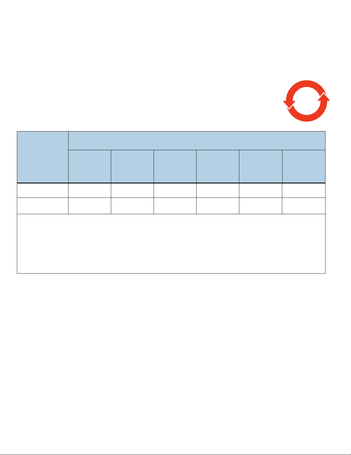
2.1.5 China Requirements — China RoHS 2
20
China RoHS 2 refers to the Ministry of Industry and Information Technology Order No. 32, effective July 1, 2016, titled Management
Methods for the Restriction of the Use of Hazardous Substances in Electrical and Electronic Products. To comply with China RoHS 2,
we determined this product's Environmental Protection Use Period (EPUP) to be 20 years in accordance with the Marking for the
Restricted Use of Hazardous Substances in Electronic and Electrical Products, SJT 11364-2014.
中国电器电子产品有害物质限制使用管理办法
(Management Methods for the Restriction of the Use of Hazardous Substances in Electrical and Electronic
Products _ China RoHS)
产品中有害物质的名称及含量
(Name and Content of the Hazardous Substances in Product)
Table 1 Hazardous Substances
有害物质
Hazardous Substances
部件名称
Part Name
印刷电路板组装
PCBA
机壳
Chassis
本表格依据 SJ/T 11364 的规定编制。
This table is prepared in accordance with the provisions of SJ/T 11364-2014
O:表示该有害物质在该部件所有均质材料中的含量均在 GB/T 26572 规定的限量要求以下。
O: Indicates that the hazardous substance contained in all of the homogeneous materials for this part is below the limit requirement of
GB/T26572.
X:表示该有害物质至少在该部件的某一均质材料中的含量超出 GB/T 26572 规定的限量要求。
X: Indicates that the hazardous substance contained in at least one of the homogeneous materials used for this part is above the limit
requirement of GB/T26572.
Reference documents
SCSI Commands Reference Manual Seagate part number: 100293068
SAS Interface Manual Seagate part number: 100293071
ANSI SAS Documents
铅
Lead
(Pb)
XOOOOO
XOOOOO
SFF-8223 2.5” Drive Form Factor with Serial Connector
SFF-8460 HSS Backplane Design Guidelines
SFF-8470 Multi Lane Copper Connector
SFF-8482 SAS Plug Connector
ANSI INCITS.xxx Serial Attached SCSI (SAS-3) Standard (T10//BSR INCITS 519 rev. 06)
ISO/IEC 14776-xxx SCSI Architecture Model-3 (SAM-4) Standard (T10/1683-D)
ISO/IEC 14776-xxx SCSI Primary Commands-3 (SPC-3) Standard (T10/1416-D)
ISO/IEC 14776-xxx SCSI Block Commands-3 (SBC-2) Standard (T10/1417-D)
汞
Mercury
(Hg)
镉
Cadmium
(Cd)
六价铬
Hexavalent
Chromium
+6
)
(CF
多溴联苯
Polybrominated
biphenyls
(PBB)
多溴二苯醚
Polybrominated
diphenyl ethers
(PBDE)
ANSI Small Computer System Interface (SCSI) Documents
X3.270-1996 (SCSI-3) Architecture Model
Trusted Computing Group (TCG) Documents (apply to Self-Encrypting Drive models only)
TCG Storage Architecture Core Specification, Rev. 1.0
TCG Storage Security Subsystem Class Enterprise Specification, Rev. 1.0
Self-Encrypting Drives Reference Manual Seagate part number: 100515636
In case of conflict between this document and any referenced document, this document takes precedence.
Seagate Enterprise Performance 10K HDD v9 Product Manual, Rev. D (Draft 2) 11

3.0 General description
Seagate® Enterprise Performance 10K HDD drives provide high performance, high capacity data storage for a variety of systems
including engineering workstations, network servers, mainframes, and supercomputers. The Serial Attached SCSI interface is
designed to meet next-generation computing demands for performance, scalability, flexibility and high-density storage
requirements.
The Advanced Caching functionality (available on 512E/4Kn only) provides improved performance over standard HDDs in real-world
workloads. This improvement is due to the addition of a solid state component that caches “hot” data for reads as well as protects
write data via non-volatile cache (NVC).
Seagate Enterprise Performance 10K HDD drives are random access storage devices designed to support the Serial Attached SCSI
Protocol as described in the ANSI specifications, this document, and the SAS Interface Manual (part number 100293071) which
describes the general interface characteristics of this drive. Seagate Enterprise Performance 10K HDD drives are classified as
intelligent peripherals and provide level 2 conformance (highest level) with the ANSI SCSI-1 standard. The SAS connectors, cables
and electrical interface are compatible with Serial ATA (SATA), giving future users the choice of populating their systems with either
SAS or SATA hard disk drives. This allows integrators to continue to leverage existing investment in SCSI while gaining a 12Gb/s serial
data transfer rate.
Never disassemble the HDA and do not attempt to service items in the sealed enclosure
Note
Seagate Enterprise Performance 10K HDD drives use a dedicated load/unload zone at the outermost radius of the media to eliminate
the possibility of destroying or degrading data by landing in the data zone. The heads automatically go to the ramp load/unload
when power is removed from the drive and during the deeper sleep modes.
(heads, media, actuator, etc.) as this requires special facilities. The drive does not contain userreplaceable parts. Opening the HDA for any reason voids the warranty.
An automatic shipping lock prevents potential damage to the heads and discs that results from movement during shipping and
handling. The shipping lock disengages and the head load process begins when power is applied to the drive.
The drives also use a high-performance actuator assembly with a low-inertia, balanced, patented, straight arm design that provides
excellent performance with minimal power dissipation in any orientation.
3.1 Standard features
Enterprise Performance 10K HDD drives have the following standard features:
• 128 - deep task set (queue)
• 256MB / 128MB data buffer (see Section 4.5)
• 3.0 / 6.0 / 12.0 Gb Serial Attached SCSI (SAS) interface
• 8MB NVC-backed write cache 512E/4Kn only
• Dedicated head load/unload zone and automatic shipping lock
•Drive Self Test (DST)
• Dynamic spindle brake
• ECC maximum burst correction length of 520 bits for 512 byte blocks and 3000 bits for 4K byte blocks.
• Embedded servo design
• Firmware downloadable using the SAS interface
• Flawed logical block reallocation at format time
• Idle Read After Write (IRAW)
• Industry standard SFF 2.5-inch dimensions
• Integrated dual port SAS controller supporting the SCSI protocol
• Jumperless configuration
• Multi-Sensor Magnetic Recording (implements dual readers)
• No preventive maintenance or adjustments required
• Power Balance supported (see Section 6.2 on page 26)
•Power Choice
• Programmable auto write and read reallocation
• Programmable logical block reallocation scheme
•RAID Rebuild ™
• Reallocation of defects on command (Post Format)
•SAS Power Disable
• Self diagnostics performed when power is applied to the drive
Seagate Enterprise Performance 10K HDD v9 Product Manual, Rev. D (Draft 2) 12

• Support for SAS expanders and fanout adapters
• Supports up to 32 initiators
• T10 Fast Format supported (see Section 4.2.2)
• TurboBoost 16GB read cache 512E/4Kn only
• User-selectable logical block sizes for 4096 native models (4096, 4160 or 4224 bytes per logical block)
• User-selectable logical block sizes for 512 emulation and native models (512, 520 or 528 bytes per logical block)
• Vertical, horizontal, or top down mounting
• Zone bit recording (ZBR)
Seagate Enterprise Performance 10K HDD Self-Encrypting Drive models have the following additional features:
• 32 independent data bands
• Authenticated firmware download
• Automatic data encryption/decryption
• Controlled access
• Cryptographic erase of user data for a drive that will be repurposed or scrapped
•Drive locking
•Random number generator
3.2 Media description
The media used on the drive has an glass substrate coated with a thin film magnetic material, overcoated with a proprietary
protective layer for improved durability and environmental protection.
3.3 Performance
• 10.5K RPM spindle. Average latency = 2.9ms
• 1200MB/s maximum instantaneous data transfers.
• Adaptive seek velocity; improved seek performance
• Background processing of queue
• Firmware-controlled multisegmented cache designed to dynamically adjust segments for enhanced system performance
• Supports start and stop commands (spindle stops spinning)
Note
There is no significant performance difference between Self-Encrypting
Drive and standard (non-Self-Encrypting Drive) models.
3.4 Formatted capacities
Standard OEM models are formatted to 512 bytes per block for 512 emulation and native drives and 4096 bytes per block for 4096
native drives. The block size is selectable at format time. Supported block sizes are 512, 520 and 528 for 512 emulation and native
drives and 4096, 4160 and 4224 for 4096 native drives. Users having the necessary equipment may modify the data block size before
issuing a format command and obtain different formatted capacities than those listed.
To provide a stable target capacity environment and at the same time provide users with flexibility if they choose, Seagate
recommends product planning in one of two modes:
Seagate designs specify capacity points at certain block sizes that Seagate guarantees current and future products will meet. We
recommend customers use this capacity in their project planning, as it ensures a stable operating point with backward and forward
compatibility from generation to generation. The current guaranteed operating points for this product are shown below.
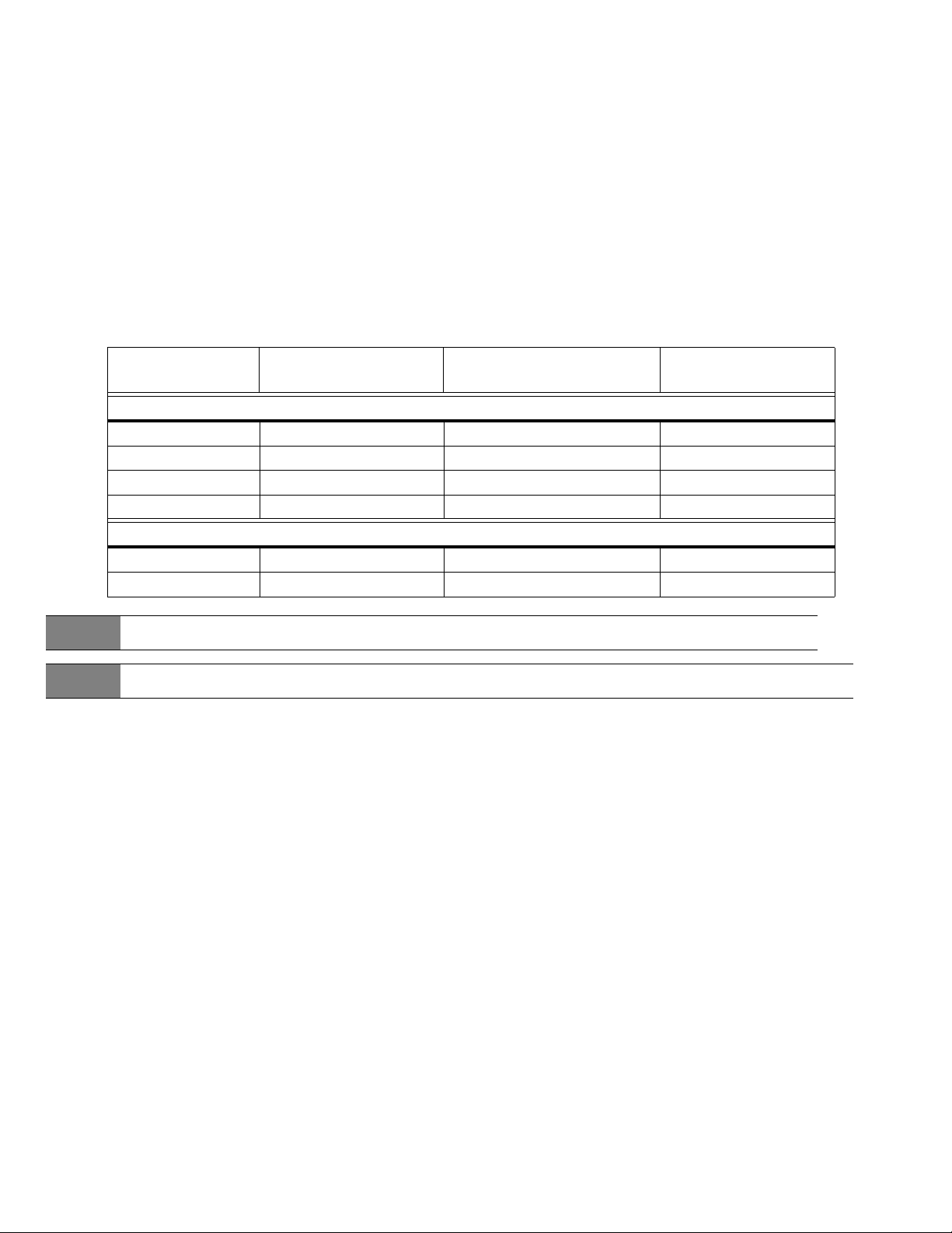
Seagate Enterprise Performance 10K HDD v9 Product Manual, Rev. D (Draft 2) 13

Capacity (Blocks)
Sector
Size
512
520
528
4096
4160
4224
Decimal Hex Decimal Hex Decimal Hex Decimal Hex
4,688,430,768 11773C6B0 3,516,328,368 D196E9B0h 2,344,225,968 8BBA0CB0h 1,172,123,568 45DD2FB0h
4,589,230,784 1118A1AC0 3,441,923,088 CD279410h 2,294,615,392 88C50D60h 1,147,307,696 446286B0h
4,462,998,224 10A03F2D0 3,347,248,672 C782F620h 2,231,499,112 8501F968h 1,115,749,560 4280FCB8h
586,053,846 22EE78D6 439,541,046 1A32DD36h 293,028,246 11774196h 146,515,446 8BBA5F6h
574,615,392 223FEF60 430,961,544 19AFF388h 287,307,696 111FF7B0h 143,653,848 88FFBD8h
563,068,183 218FBD18 422,301,144 192BCDD8h 281,534,096 10C7DE90h 140,767,048 863EF48h
2400GB 1800GB 1200GB 600GB
3.5 Programmable drive capacity
Using the Mode Select command, the drive can change its capacity to something less than maximum. See the Mode Select (6)
parameter list table in the SAS Interface Manual, part number 100293071. A value of zero in the Number of Blocks field indicates that
the drive will not change the capacity it is currently formatted to have. A number other than zero and less than the maximum
number of LBAs in the Number of Blocks field changes the total drive capacity to the value in the Number of Blocks field. A value
greater than the maximum number of LBAs is rounded down to the maximum capacity.
3.6 Factory-installed options
The following items may be ordered which are incorporated at the manufacturing facility during production or packaged before
shipping. Some of the options available are (not an exhaustive list of possible options):
• Other capacities can be ordered depending on sparing scheme and sector size requested.
• Single-unit shipping pack. The drive is normally shipped in bulk packaging to provide maximum protection against transit damage. Units shipped individually require additional protection as provided by the single unit shipping pack. Users planning single
unit distribution should specify this option.
•The Safety and Regulatory Agency Specifications, part number 75789512, is usually included with each standard OEM drive shipped,
but extra copies may be ordered.
Seagate Enterprise Performance 10K HDD v9 Product Manual, Rev. D (Draft 2) 14

4.0 Performance characteristics
This section provides detailed information concerning performance-related characteristics and features of Seagate Enterprise
Performance 10K HDD drives.
4.1 Internal drive characteristics
2400GB 1800GB 1200GB 600GB Models
Sector size 4KN or 512E 4KN or 512E 4KN or 512E / 512N 4KN or 512E / 512N
Drive capacity 2.4TB 1.8TB 1.2TB 0.6TB GB (formatted, rounded off value)
Read/write data heads 8 6 4 2
Bytes per track 1261 1261 1261 / 1168 1261 / 1168 Kbytes (avg, rounded off values)
Bytes per surface 300,016 300,016 300,016 300,016 MB (unformatted, rounded off value)
Tracks per surface (total) 249 249 249 249 Ktracks (user accessible, rounded off values)
Tracks per inch 342 342 342 / 369 342 / 369 KTPI (avg, rounded off values)
Peak bits per inch 2460 2460 2460 2460 Kb/in
Areal density 841 841 841 / 908 841 / 908 Gb/in2
Disk rotation speed 10.5K 10.5K 10.5K 10.5K rpm
Avg rotational latency 2.9 2.9 2.9 2.9 ms
4.2 Performance characteristics
4.2.1 Format command execution time (minutes)
2400GB models 1800GB models 1200GB models 600GB models
Maximum (with verify)
Maximum (without verify)
420
210
320 220 120
160 110 60
Execution time measured from receipt of the last byte of the Command Descriptor Block (CDB) to the request for a Status Byte
Transfer to the Initiator (excluding connect/disconnect).
When changing sector sizes, the format times shown above may need to be increased by 30 minutes.
Seagate Enterprise Performance 10K HDD v9 Product Manual, Rev. D (Draft 2) 15

4.2.2 Fast Format
Drive sector size transition
• Single code to support sector sizes from 512E to 4KN
• T10 fast format conversion between 4KNand 512E configurations in the field.
• Possible only if sector sizes are exact multiples of 8 & vice versa
• The selected sector size will take effect only after fast format or full format
• Drive default is 512E from the factory.
• 512E / 4KN features set after Fast Format
T10 Fast Format
• Implements the fast format based on T10 Spec.
• To request Fast Format, the FFMT bits (Byte 4, Bits 1:0) should be set to 01b.
• A setting of 10b or 11b will return a check condition with 05/24 sense code (pointing to FFMT MSB in CDB).
Mode Select - Parameter list header
• Set Write buffer: // Set Block Descriptor Length = 0x08, Number of LBA's = 0xFFFFFFFF
• 00 00 00 00 00 00 00 08 FF FF FF FF 00 00 02 00 // Set block size to 0512 (0x0200)
• 10 00 // Set block size to 4096 (0x1000)
• Then Send Mode Select Command
• cdb: 55 01 00 00 00 00 00 00 10 00 // (SP bit = 1, Parameter list = 0x10)
Format Unit - Parameter list header
• Set Write buffer: // Set IMMED = 1
• 00 02 00 00
• Then Send Format Unit Command
• cdb: 04 14 00 00 01 00 // (FMTDAT = 1, DEFECT LIST FORMAT = 010b, FFMT = 01b)
4.2.3 General performance characteristics
Sustained transfer rate for 4096 native and 512 emulation models
Sustained transfer rate for 512 native models
SAS Interface maximum instantaneous transfer rate
Logical block sizes
512 emulation and native - 512 (default), 520 or 528
4096 native - 4096 (default), 4160 or 4224
Read/write consecutive sectors on a track Ye s
Flaw reallocation performance impact (for flaws reallocated at format time using the spare
sectors per sparing zone reallocation scheme.)
Average rotational latency 2.9ms
*Assumes no errors and no relocated logical blocks. Rate measured from the start of the first logical block transfer to or from the host.
** MiB/s x 1.048 = MB/s
124 to 254 MiB/s **
130 to 266 MB/s
124 to 238 MiB/s **
130 to 250 MB/s
1200 MB/s* per port
(dual port = 2400 MB/s*)
Negligible
Seagate Enterprise Performance 10K HDD v9 Product Manual, Rev. D (Draft 2) 16

4.3 Start/stop time
The drive accepts the commands listed in the SAS Interface Manual less than 3 seconds after DC power has been applied.
If the drive receives a NOTIFY (ENABLE SPINUP) primitive through either port and has not received a START STOP UNIT command with
the START bit equal to 0, the drive becomes ready for normal operations within 20 seconds (excluding the error recovery procedure).
If the drive receives a START STOP UNIT command with the START bit equal to 0 before receiving a NOTIFY (ENABLE SPINUP)
primitive, the drive waits for a START STOP UNIT command with the START bit equal to 1. After receiving a START STOP UNIT
command with the START bit equal to 1, the drive waits for a NOTIFY (ENABLE SPINUP) primitive. After receiving a NOTIFY (ENABLE
SPINUP) primitive through either port, the drive becomes ready for normal operations within 20 seconds (excluding the error
recovery procedure).
If the drive receives a START STOP UNIT command with the START bit and IMMED bit equal to 1 and does not receive a NOTIFY
(ENABLE SPINUP) primitive within 5 seconds, the drive fails the START STOP UNIT command.
The START STOP UNIT command may be used to command the drive to stop the spindle. Stop time is 20 seconds (maximum) from
removal of DC power. SCSI stop time is 20 seconds. There is no power control switch on the drive. However, power can be cycled on
the drive by utilizing SAS Power Disable feature defined by T10 (i.e. drive Pin 3 high).
4.4 Prefetch/multi-segmented cache control
The drive provides a prefetch (read look-ahead) and multi-segmented cache control algorithms that in many cases can enhance
system performance. Cache refers to the drive buffer storage space when it is used in cache operations. To select this feature, the
host sends the Mode Select command with the proper values in the applicable bytes in page 08h. Prefetch and cache operations are
independent features from the standpoint that each is enabled and disabled independently using the Mode Select command;
however, in actual operation, the prefetch feature overlaps cache operation somewhat as described in sections 4.5.1 and 4.5.2.
All default cache and prefetch mode parameter values (Mode Page 08h) for standard OEM versions of this drive family are given in
Section 11.3.2.
4.5 Cache operation
Note. Refer to the SAS Interface Manual for more detail concerning the cache bits.
The buffer is divided into logical segments from which data is read and to which data is written.
The drive keeps track of the logical block addresses of the data stored in each segment of the buffer. If the cache is enabled (see RCD
bit in the SAS Interface Manual ), data requested by the host with a read command is retrieved from the buffer, if possible, before any
disk access is initiated. If cache operation is not enabled, the buffer is still used, but only as circular buffer segments during disk
medium read operations (disregarding Prefetch operation for the moment). That is, the drive does not check in the buffer segments
for the requested read data, but goes directly to the medium to retrieve it. The retrieved data merely passes through some buffer
segment on the way to the host. All data transfers to the host are in accordance with buffer-full ratio rules. See the explanation
provided with the information about Mode Page 02h (disconnect/reconnect control) in the SAS Interface Manual.
The following is a simplified description of the prefetch/cache operation:
Case A—read command is received and all of the requested logical blocks are already in the cache:
1. Drive transfers the requested logical blocks to the initiator.
Case B—A Read command requests data, and at least one requested logical block is not in any segment of the cache:
1. The drive fetches the requested logical blocks from the disk and transfers them into a segment, and then from there to the host
in accordance with the Mode Select Disconnect/Reconnect parameters, page 02h.
2. If the prefetch feature is enabled, refer to section 4.5.2 for operation from this point.
Each cache segment is actually a self-contained circular buffer whose length is an integer number of logical blocks. The drive
dynamically creates and removes segments based on the workload. The wrap-around capability of the individual segments greatly
enhances the cache’s overall performance.
The size of each segment is not reported by Mode Sense command page 08h, bytes 14 and 15. The value 0XFFFF is always
Note
Seagate Enterprise Performance 10K HDD v9 Product Manual, Rev. D (Draft 2) 17
reported regardless of the actual size of the segment. Sending a size specification using the Mode Select command (bytes
14 and 15) does not set up a new segment size. If the STRICT bit in Mode page 00h (byte 2, bit 1) is set to one, the drive
responds as it does for any attempt to change an unchangeable parameter.

4.5.1 Caching write data
Note
Note
Write caching in this section is the traditional SCSI write caching (WCE=1) where writes are not protected on power loss.
Advanced Caching (512E/4Kn only) provides NVC-protected write caching when WCE=0 over a portion of the DRAM.
Refer to the SAS Interface Manual for more detail concerning the cache bits.
Write caching is a write operation by the drive that makes use of a drive buffer storage area where the data to be written to the
medium is stored while the drive performs the Write command.
If read caching is enabled (RCD=0), then data written to the medium is retained in the cache to be made available for future read
cache hits. The same buffer space and segmentation is used as set up for read functions. The buffer segmentation scheme is set up or
changed independently, having nothing to do with the state of RCD. When a write command is issued, if RCD=0, the cache is first
checked to see if any logical blocks that are to be written are already stored in the cache from a previous read or write command. If
there are, the respective cache segments are cleared. The new data is cached for subsequent Read commands.
If the number of write data logical blocks exceed the size of the segment being written into, when the end of the segment is reached,
the data is written into the beginning of the same cache segment, overwriting the data that was written there at the beginning of
the operation; however, the drive does not overwrite data that has not yet been written to the medium.
If write caching is enabled (WCE=1), then the drive may return Good status on a write command after the data has been transferred
into the cache, but before the data has been written to the medium. If an error occurs while writing the data to the medium, and
Good status has already been returned, a deferred error will be generated.
The Synchronize Cache command may be used to force the drive to write all cached write data to the medium. Upon completion of a
Synchronize Cache command, all data received from previous write commands will have been written to the medium. Section 11.3.2
shows the mode default settings for the drive.
4.5.2 Prefetch operation
If the Prefetch feature is enabled, data in contiguous logical blocks on the disk immediately beyond that which was requested by a
Read command are retrieved and stored in the buffer for immediate transfer from the buffer to the host on subsequent Read
commands that request those logical blocks (this is true even if cache operation is disabled). Though the prefetch operation uses the
buffer as a cache, finding the requested data in the buffer is a prefetch hit, not a cache operation hit.
To enable Prefetch, use Mode Select page 08h, byte 12, bit 5 (Disable Read Ahead - DRA bit). DRA bit = 0 enables prefetch.
The drive does not use the Max Prefetch field (bytes 8 and 9) or the Prefetch Ceiling field (bytes 10 and 11).
When prefetch (read look-ahead) is enabled (enabled by DRA = 0), the drive enables prefetch of contiguous blocks from the disk
when it senses that a prefetch hit will likely occur. The drive disables prefetch when it decides that a prefetch hit is not likely to occur.
4.5.3 Advanced Caching (512E/4Kn only) operations
Read data that has been promoted into the Advanced read cache does not persist through a power cycle. Read data is retrieved from
the rotating media after a power cycle.
When WCE=0, Advanced provides NVC-protected write caching over the portion of the DRAM used to coalesce writes. Write data
only goes into NVC when there is an unexpected power loss to the drive. The NVC has 90-day data retention. When WCE=1, a
Advanced Caching drive will operate on writes like a standard drive–writes in cache are not protected by NVC and may be lost with
power loss.
Seagate Enterprise Performance 10K HDD v9 Product Manual, Rev. D (Draft 2) 18

5.0 Reliability specifications
The following reliability specifications assume correct host and drive operational interface, including all interface timings, power
supply voltages, environmental requirements and drive mounting constraints.
8
Seek error rate: Less than 10 errors in 10
Read Error Rates
1
Recovered Data Less than 10 error in 1012 bits transferred (OEM default settings)
Unrecovered Data Less than 1 sector in 10
Miscorrected Data Less than 1 sector in 10
Interface error rate: Less than 1 error in 10
Mean Time Between Failure (MTBF): 2,000,000 hours
Annualized Failure Rate (AFR): 0.44%
Preventive maintenance: None required
1. Error rate specified with automatic retries and data correction with ECC enabled and all flaws reallocated.
5.1 Error rates
The error rates stated in this manual assume the following:
• The drive is operated in accordance with this manual using DC power as defined in paragraph 6.4, "DC power consumption."
• Errors caused by host system failures are excluded from error rate computations.
• Assume random data.
• Default OEM error recovery settings are applied. This includes AWRE, ARRE, full read retries, full write retries and full retry time.
seeks
16
bits transferred
21
bits transferred
12
bits transferred
5.1.1 Recoverable Errors
Recoverable errors are those detected and corrected by the drive, and do not require user intervention.
Recoverable Data errors will use Error Correction when needed.
Recovered Data error rate is determined using read bits transferred for recoverable errors occurring during a read, and using write
bits transferred for recoverable errors occurring during a write.
5.1.2 Unrecoverable Errors
An unrecoverable data error is defined as a failure of the drive to recover data from the media. These errors occur due to head/media
or write problems. Unrecoverable data errors are only detected during read operations, but not caused by the read. If an
unrecoverable data error is detected, a MEDIUM ERROR (03h) in the Sense Key will be reported. Multiple unrecoverable data errors
resulting from the same cause are treated as 1 error.
5.1.3 Seek errors
A seek error is defined as a failure of the drive to position the heads to the addressed track. After detecting an initial seek error, the
drive automatically performs an error recovery process. If the error recovery process fails, a seek positioning error (Error code = 15h
or 02h) will be reported with a Hardware error (04h) in the Sense Key. Recoverable seek errors are specified at Less than 10 errors in
108 seeks. Unrecoverable seek errors (Sense Key = 04h) are classified as drive failures.
5.1.4 Interface errors
An interface error is defined as a failure of the receiver on a port to recover the data as transmitted by the device port connected to
the receiver. The error may be detected as a running disparity error, illegal code, loss of word sync, or CRC error.
Seagate Enterprise Performance 10K HDD v9 Product Manual, Rev. D (Draft 2) 19
5.2 Reliability and service
The reliability of Seagate Enterprise Performance 10K HDD disk drives can be enhanced by ensuring that the drive receives adequate
cooling. Section 6.0 provides temperature measurements and other information that may be used to enhance the service life of the
drive. Section 10.2 provides recommended air-flow information.
5.2.1 Annualized Failure Rate (AFR) and Mean Time Between Failure (MTBF)
The production disk drive shall achieve an annualized failure-rate of 0.44% (MTBF of 2,000,000 hours) over a 5 year service life when
used in Enterprise Storage field conditions as limited by the following:
• 8760 power-on hours per year.
• HDA temperature as reported by the drive <= 50°C
• Ambient wet bulb temp <= 26°C
•Typical workload
• The AFR (MTBF) is a population statistic not relevant to individual units.
• ANSI/ISA S71.04-2013 G2 classification levels and dust contamination to ISO 14644-1 Class 8 standards (as measured at the
device)
The MTBF specification for the drive assumes the operating environment is designed to maintain nominal drive temperature and
humidity. Occasional excursions in operating conditions between the rated MTBF conditions and the maximum drive operating
conditions may occur without significant impact to the rated MTBF. However continual or sustained operation beyond the rated
MTBF conditions will degrade the drive MTBF and reduce product reliability.
5.2.2 Preventive maintenance
No routine scheduled preventive maintenance is required.
5.2.3 Hot plugging the drive
When a disk is powered on by switching the power or hot plugged, the drive runs a self test before attempting to communicate on
its’ interfaces. When the self test completes successfully, the drive initiates a Link Reset starting with OOB. An attached device should
respond to the link reset. If the link reset attempt fails, or any time the drive looses sync, the drive initiated link reset. The drive will
initiate link reset once per second but alternates between port A and B. Therefore each port will attempt a link reset once per 2
seconds assuming both ports are out of sync.
If the self-test fails, the drive does not respond to link reset on the failing port.
It is the responsibility of the systems integrator to assure that no temperature, energy, voltage hazard,
Note
Caution
shorting of PCBA to ground, or ESD potential hazard is presented during the hot connect/disconnect
operation. Discharge the static electricity from the drive carrier prior to inserting it into the system.
The drive motor must come to a complete stop prior to changing the
plane of operation. This time is required to insure data integrity.
5.2.4 S.M.A.R.T.
S.M.A.R.T. is an acronym for Self-Monitoring Analysis and Reporting Technology. This technology is intended to recognize conditions
that indicate imminent drive failure and is designed to provide sufficient warning of a failure to allow an application to back up the
data before an actual failure occurs.
Note
The drive’s firmware monitors specific attributes for degradation
over time but can’t predict instantaneous drive failures.
Each monitored attribute has been selected to monitor a specific set of failure conditions in the operating performance of the drive
and the thresholds are optimized to minimize “false” and “failed” predictions.
Seagate Enterprise Performance 10K HDD v9 Product Manual, Rev. D (Draft 2) 20
 Loading...