

Page 1

. . . . . . . . . . . . . . . . . . . . . . . . . . . . . . . . . . . . . . . . . . . . . . . . .
Barracuda 180 Family:
. . . . . . . . . . . . . . . . . . . . . . . . . . . . . . . . . . . . . . . . . . . . . . . . .
ST1181677LW/LWV/LC/LCV
. . . . . . . . . . . . . . . . . . . . . . . . . . . . . . . . . . . . . . . . . . . . . . . . .
. . . . . . . . . . . . . . . . . . . . . . . . . . . . . . . . . . . . . . . . . . . . . . . . .
. . . . . . . . . . . . . . . . . . . . . . . . . . . . . . . . . . . . . . . . . . . . . . . . .
Product Manual, Volume 1
. . . . . . . . . . . . . . . . . . . . . . . . . . . . . . . . . . . . . . . . . . . . . . . . .
Page 2

Page 3

. . . . . . . . . . . . . . . . . . . . . . . . . . . . . . . . . . . . . . . . . . . . . . . . .
Barracuda 180 Family:
. . . . . . . . . . . . . . . . . . . . . . . . . . . . . . . . . . . . . . . . . . . . . . . . .
ST1181677LW/LWV/LC/LCV
. . . . . . . . . . . . . . . . . . . . . . . . . . . . . . . . . . . . . . . . . . . . . . . . .
. . . . . . . . . . . . . . . . . . . . . . . . . . . . . . . . . . . . . . . . . . . . . . . . .
. . . . . . . . . . . . . . . . . . . . . . . . . . . . . . . . . . . . . . . . . . . . . . . . .
Product Manual, Volume 1
. . . . . . . . . . . . . . . . . . . . . . . . . . . . . . . . . . . . . . . . . . . . . . . . .
Page 4

© 2000 Seagate Technology LLC All rights reserved
Publication number: 100109939, Rev. A
November 2000
Seagate, Seagate Technology, and the Seagate logo are registered tradema rks of Seagate Technology LLC.
Cheetah, SeaFAX, SeaFONE, SeaBOARD, and SeaTDD are either trademarks or registered trademarks of
Seagate Technology LLC or one of its subsidiaries. All other trademarks or registered trademarks are the property of their respective owners.
Seagate reserves the right to change, without notice, product offerings or specifications. No part of this publica-
tion may be reproduced in any form without written permission of Seagate Technology LLC.
Page 5

Revision status summary sheet
Revision Date Writer/Engineer Sheets Affected
Rev. A (Class A Release) 11/9/2000 L. Newman/J. Nowitzke 1/1, v thru viii, 1-74.
Notice.
Product Manual 100109939 is Volume 1 of a two volume document with the SCSI interface information
in the SCSI Interface Product Manual, Volume 2, part number 75789509.
If you need the SCSI interface information, order the SCSI Interface Product Manual, Volume 2,
part number 75789509.
Page 6

Page 7

Barracuda 180 Product Manual, Rev. A v
Contents
1.0 Scope . . . . . . . . . . . . . . . . . . . . . . . . . . . . . . . . . . . . . . . . . . . . . . . . . . . . . . . . . . . . . . . . . . . . . . . . . . 1
2.0 Applicable standards and reference documentation. . . . . . . . . . . . . . . . . . . . . . . . . . . . . . . . . . . . 3
2.1 Standards. . . . . . . . . . . . . . . . . . . . . . . . . . . . . . . . . . . . . . . . . . . . . . . . . . . . . . . . . . . . . . . . . 3
2.1.1 Electromagnetic compatibility . . . . . . . . . . . . . . . . . . . . . . . . . . . . . . . . . . . . . . . . . . 3
2.1.2 Electromagnetic susceptibility. . . . . . . . . . . . . . . . . . . . . . . . . . . . . . . . . . . . . . . . . . 3
2.2 Electromagnetic compliance . . . . . . . . . . . . . . . . . . . . . . . . . . . . . . . . . . . . . . . . . . . . . . . . . . 3
2.3 Reference documents . . . . . . . . . . . . . . . . . . . . . . . . . . . . . . . . . . . . . . . . . . . . . . . . . . . . . . . 4
3.0 General description. . . . . . . . . . . . . . . . . . . . . . . . . . . . . . . . . . . . . . . . . . . . . . . . . . . . . . . . . . . . . . . 5
3.1 Standard features. . . . . . . . . . . . . . . . . . . . . . . . . . . . . . . . . . . . . . . . . . . . . . . . . . . . . . . . . . . 7
3.2 Media characteristics . . . . . . . . . . . . . . . . . . . . . . . . . . . . . . . . . . . . . . . . . . . . . . . . . . . . . . . . 7
3.3 Performance. . . . . . . . . . . . . . . . . . . . . . . . . . . . . . . . . . . . . . . . . . . . . . . . . . . . . . . . . . . . . . . 7
3.4 Reliability . . . . . . . . . . . . . . . . . . . . . . . . . . . . . . . . . . . . . . . . . . . . . . . . . . . . . . . . . . . . . . . . . 7
3.5 Unformatted and formatted capacities . . . . . . . . . . . . . . . . . . . . . . . . . . . . . . . . . . . . . . . . . . . 8
3.6 Programmable drive capacity. . . . . . . . . . . . . . . . . . . . . . . . . . . . . . . . . . . . . . . . . . . . . . . . . . 8
3.7 Factory installed accessories. . . . . . . . . . . . . . . . . . . . . . . . . . . . . . . . . . . . . . . . . . . . . . . . . . 8
3.8 Options (factory installed). . . . . . . . . . . . . . . . . . . . . . . . . . . . . . . . . . . . . . . . . . . . . . . . . . . . . 8
3.9 Accessories (user installed) . . . . . . . . . . . . . . . . . . . . . . . . . . . . . . . . . . . . . . . . . . . . . . . . . . . 8
4.0 Performance characteristics . . . . . . . . . . . . . . . . . . . . . . . . . . . . . . . . . . . . . . . . . . . . . . . . . . . . . . . 9
4.1 Internal drive characteristics (transparent to user). . . . . . . . . . . . . . . . . . . . . . . . . . . . . . . . . . 9
4.2 SCSI performance characteristics (visible to user) . . . . . . . . . . . . . . . . . . . . . . . . . . . . . . . . . 9
4.2.1 Access time . . . . . . . . . . . . . . . . . . . . . . . . . . . . . . . . . . . . . . . . . . . . . . . . . . . . . . . 9
4.2.2 Format command execution time (minutes) . . . . . . . . . . . . . . . . . . . . . . . . . . . . . . . 9
4.2.3 Generalized performance characteristics . . . . . . . . . . . . . . . . . . . . . . . . . . . . . . . . . 9
4.3 Start/stop time . . . . . . . . . . . . . . . . . . . . . . . . . . . . . . . . . . . . . . . . . . . . . . . . . . . . . . . . . . . . 10
4.4 Prefetch/multi-segmented cache control . . . . . . . . . . . . . . . . . . . . . . . . . . . . . . . . . . . . . . . . 10
4.5 Cache operation. . . . . . . . . . . . . . . . . . . . . . . . . . . . . . . . . . . . . . . . . . . . . . . . . . . . . . . . . . . 10
4.5.1 Caching write data . . . . . . . . . . . . . . . . . . . . . . . . . . . . . . . . . . . . . . . . . . . . . . . . . 11
4.5.2 Prefetch operation . . . . . . . . . . . . . . . . . . . . . . . . . . . . . . . . . . . . . . . . . . . . . . . . . 12
5.0 Reliability specifications . . . . . . . . . . . . . . . . . . . . . . . . . . . . . . . . . . . . . . . . . . . . . . . . . . . . . . . . . 13
5.1 Error rates . . . . . . . . . . . . . . . . . . . . . . . . . . . . . . . . . . . . . . . . . . . . . . . . . . . . . . . . . . . . . . . 13
5.1.1 Environmental interference. . . . . . . . . . . . . . . . . . . . . . . . . . . . . . . . . . . . . . . . . . . 13
5.1.2 Read errors. . . . . . . . . . . . . . . . . . . . . . . . . . . . . . . . . . . . . . . . . . . . . . . . . . . . . . . 13
5.1.3 Write errors. . . . . . . . . . . . . . . . . . . . . . . . . . . . . . . . . . . . . . . . . . . . . . . . . . . . . . . 13
5.1.4 Seek errors . . . . . . . . . . . . . . . . . . . . . . . . . . . . . . . . . . . . . . . . . . . . . . . . . . . . . . . 13
5.2 Reliability and service. . . . . . . . . . . . . . . . . . . . . . . . . . . . . . . . . . . . . . . . . . . . . . . . . . . . . . . 14
5.2.1 Mean time between failure . . . . . . . . . . . . . . . . . . . . . . . . . . . . . . . . . . . . . . . . . . . 14
5.2.2 Field failure rate vs. time. . . . . . . . . . . . . . . . . . . . . . . . . . . . . . . . . . . . . . . . . . . . . 14
5.2.3 Preventive maintenance . . . . . . . . . . . . . . . . . . . . . . . . . . . . . . . . . . . . . . . . . . . . . 15
5.2.4 Service life . . . . . . . . . . . . . . . . . . . . . . . . . . . . . . . . . . . . . . . . . . . . . . . . . . . . . . . 15
5.2.5 Service philosophy . . . . . . . . . . . . . . . . . . . . . . . . . . . . . . . . . . . . . . . . . . . . . . . . . 15
5.2.6 Service tools . . . . . . . . . . . . . . . . . . . . . . . . . . . . . . . . . . . . . . . . . . . . . . . . . . . . . . 15
5.2.7 Hot plugging Barracuda 180 disc drives. . . . . . . . . . . . . . . . . . . . . . . . . . . . . . . . . 15
5.2.8 S.M.A.R.T. . . . . . . . . . . . . . . . . . . . . . . . . . . . . . . . . . . . . . . . . . . . . . . . . . . . . . . . 16
5.2.9 Drive Self Test (DST) . . . . . . . . . . . . . . . . . . . . . . . . . . . . . . . . . . . . . . . . . . . . . . . 17
5.2.10 Product warranty. . . . . . . . . . . . . . . . . . . . . . . . . . . . . . . . . . . . . . . . . . . . . . . . . . . 18
6.0 Physical/electrical specifications . . . . . . . . . . . . . . . . . . . . . . . . . . . . . . . . . . . . . . . . . . . . . . . . . . 21
6.1 AC power requirements . . . . . . . . . . . . . . . . . . . . . . . . . . . . . . . . . . . . . . . . . . . . . . . . . . . . . 21
6.2 DC power requirements . . . . . . . . . . . . . . . . . . . . . . . . . . . . . . . . . . . . . . . . . . . . . . . . . . . . . 21
6.2.1 Conducted noise immunity . . . . . . . . . . . . . . . . . . . . . . . . . . . . . . . . . . . . . . . . . . . 22
6.2.2 Power sequencing . . . . . . . . . . . . . . . . . . . . . . . . . . . . . . . . . . . . . . . . . . . . . . . . . 22
6.2.3 12 V - Current profile . . . . . . . . . . . . . . . . . . . . . . . . . . . . . . . . . . . . . . . . . . . . . . . 22
6.3 Power dissipation . . . . . . . . . . . . . . . . . . . . . . . . . . . . . . . . . . . . . . . . . . . . . . . . . . . . . . . . . . 24
6.4 Environmental limits . . . . . . . . . . . . . . . . . . . . . . . . . . . . . . . . . . . . . . . . . . . . . . . . . . . . . . . . 25
Page 8

vi Barracuda 180 Product Manual, Rev. A
6.4.1 Temperature . . . . . . . . . . . . . . . . . . . . . . . . . . . . . . . . . . . . . . . . . . . . . . . . . . . . . .25
6.4.2 Relative humidity . . . . . . . . . . . . . . . . . . . . . . . . . . . . . . . . . . . . . . . . . . . . . . . . . . .25
6.4.3 Effective altitude (sea level). . . . . . . . . . . . . . . . . . . . . . . . . . . . . . . . . . . . . . . . . . .26
6.4.4 Shock and vibration . . . . . . . . . . . . . . . . . . . . . . . . . . . . . . . . . . . . . . . . . . . . . . . . .26
6.4.5 Air cleanliness . . . . . . . . . . . . . . . . . . . . . . . . . . . . . . . . . . . . . . . . . . . . . . . . . . . . .28
6.4.6 Acoustics . . . . . . . . . . . . . . . . . . . . . . . . . . . . . . . . . . . . . . . . . . . . . . . . . . . . . . . . .28
6.4.7 Electromagnetic susceptibility . . . . . . . . . . . . . . . . . . . . . . . . . . . . . . . . . . . . . . . . .28
6.5 Mechanical specifications . . . . . . . . . . . . . . . . . . . . . . . . . . . . . . . . . . . . . . . . . . . . . . . . . . . .29
7.0 Defect and error management . . . . . . . . . . . . . . . . . . . . . . . . . . . . . . . . . . . . . . . . . . . . . . . . . . . . .31
7.1 Drive internal defects. . . . . . . . . . . . . . . . . . . . . . . . . . . . . . . . . . . . . . . . . . . . . . . . . . . . . . . .31
7.2 Drive error recovery procedures . . . . . . . . . . . . . . . . . . . . . . . . . . . . . . . . . . . . . . . . . . . . . . .31
7.3 SCSI systems errors . . . . . . . . . . . . . . . . . . . . . . . . . . . . . . . . . . . . . . . . . . . . . . . . . . . . . . . .32
8.0 Installation . . . . . . . . . . . . . . . . . . . . . . . . . . . . . . . . . . . . . . . . . . . . . . . . . . . . . . . . . . . . . . . . . . . . .33
8.1 Drive ID/option select header . . . . . . . . . . . . . . . . . . . . . . . . . . . . . . . . . . . . . . . . . . . . . . . . .33
8.1.1 Notes for Figures 12, 13, and 14. . . . . . . . . . . . . . . . . . . . . . . . . . . . . . . . . . . . . . .36
8.1.2 Function description. . . . . . . . . . . . . . . . . . . . . . . . . . . . . . . . . . . . . . . . . . . . . . . . .37
8.2 Drive orientation . . . . . . . . . . . . . . . . . . . . . . . . . . . . . . . . . . . . . . . . . . . . . . . . . . . . . . . . . . .38
8.3 Cooling . . . . . . . . . . . . . . . . . . . . . . . . . . . . . . . . . . . . . . . . . . . . . . . . . . . . . . . . . . . . . . . . . .38
8.4 Drive mounting . . . . . . . . . . . . . . . . . . . . . . . . . . . . . . . . . . . . . . . . . . . . . . . . . . . . . . . . . . . .39
8.5 Grounding . . . . . . . . . . . . . . . . . . . . . . . . . . . . . . . . . . . . . . . . . . . . . . . . . . . . . . . . . . . . . . . .39
9.0 Interface requirements. . . . . . . . . . . . . . . . . . . . . . . . . . . . . . . . . . . . . . . . . . . . . . . . . . . . . . . . . . . .41
9.1 General description . . . . . . . . . . . . . . . . . . . . . . . . . . . . . . . . . . . . . . . . . . . . . . . . . . . . . . . . .41
9.2 SCSI interface messages supported. . . . . . . . . . . . . . . . . . . . . . . . . . . . . . . . . . . . . . . . . . . .41
9.3 SCSI interface commands supported . . . . . . . . . . . . . . . . . . . . . . . . . . . . . . . . . . . . . . . . . . .42
9.3.1 Inquiry Vital Product data. . . . . . . . . . . . . . . . . . . . . . . . . . . . . . . . . . . . . . . . . . . . .45
9.3.2 Mode Sense data. . . . . . . . . . . . . . . . . . . . . . . . . . . . . . . . . . . . . . . . . . . . . . . . . . .46
9.4 SCSI bus conditions and miscellaneous features supported . . . . . . . . . . . . . . . . . . . . . . . . .48
9.5 Synchronous data transfer . . . . . . . . . . . . . . . . . . . . . . . . . . . . . . . . . . . . . . . . . . . . . . . . . . .49
9.5.1 Synchronous data transfer periods supported. . . . . . . . . . . . . . . . . . . . . . . . . . . . .49
9.5.2 REQ/ACK offset. . . . . . . . . . . . . . . . . . . . . . . . . . . . . . . . . . . . . . . . . . . . . . . . . . . .49
9.6 Physical interface . . . . . . . . . . . . . . . . . . . . . . . . . . . . . . . . . . . . . . . . . . . . . . . . . . . . . . . . . .49
9.6.1 DC cable and connector . . . . . . . . . . . . . . . . . . . . . . . . . . . . . . . . . . . . . . . . . . . . .49
9.6.2 SCSI interface physical description . . . . . . . . . . . . . . . . . . . . . . . . . . . . . . . . . . . . .51
9.6.3 SCSI interface cable requirements . . . . . . . . . . . . . . . . . . . . . . . . . . . . . . . . . . . . .51
9.6.4 Mating connectors . . . . . . . . . . . . . . . . . . . . . . . . . . . . . . . . . . . . . . . . . . . . . . . . . .52
9.7 Electrical description . . . . . . . . . . . . . . . . . . . . . . . . . . . . . . . . . . . . . . . . . . . . . . . . . . . . . . . .60
9.7.1 Multimode—SE and LVD alternatives . . . . . . . . . . . . . . . . . . . . . . . . . . . . . . . . . . .60
9.8 Terminator requirements . . . . . . . . . . . . . . . . . . . . . . . . . . . . . . . . . . . . . . . . . . . . . . . . . . . . .62
9.9 Terminator power . . . . . . . . . . . . . . . . . . . . . . . . . . . . . . . . . . . . . . . . . . . . . . . . . . . . . . . . . .62
9.10 Disc drive SCSI timing. . . . . . . . . . . . . . . . . . . . . . . . . . . . . . . . . . . . . . . . . . . . . . . . . . . . . . .63
9.11 Drive activity LED . . . . . . . . . . . . . . . . . . . . . . . . . . . . . . . . . . . . . . . . . . . . . . . . . . . . . . . . . .64
10.0 Seagate Technology support services. . . . . . . . . . . . . . . . . . . . . . . . . . . . . . . . . . . . . . . . . . . . . . .65
Page 9

Barracuda 180 Product Manual, Rev. A vii
List of Figures
Figure 1. Barracuda 180 family drive (ST1181677LW shown) . . . . . . . . . . . . . . . . . . . . . . . . . . . . . . . . 1
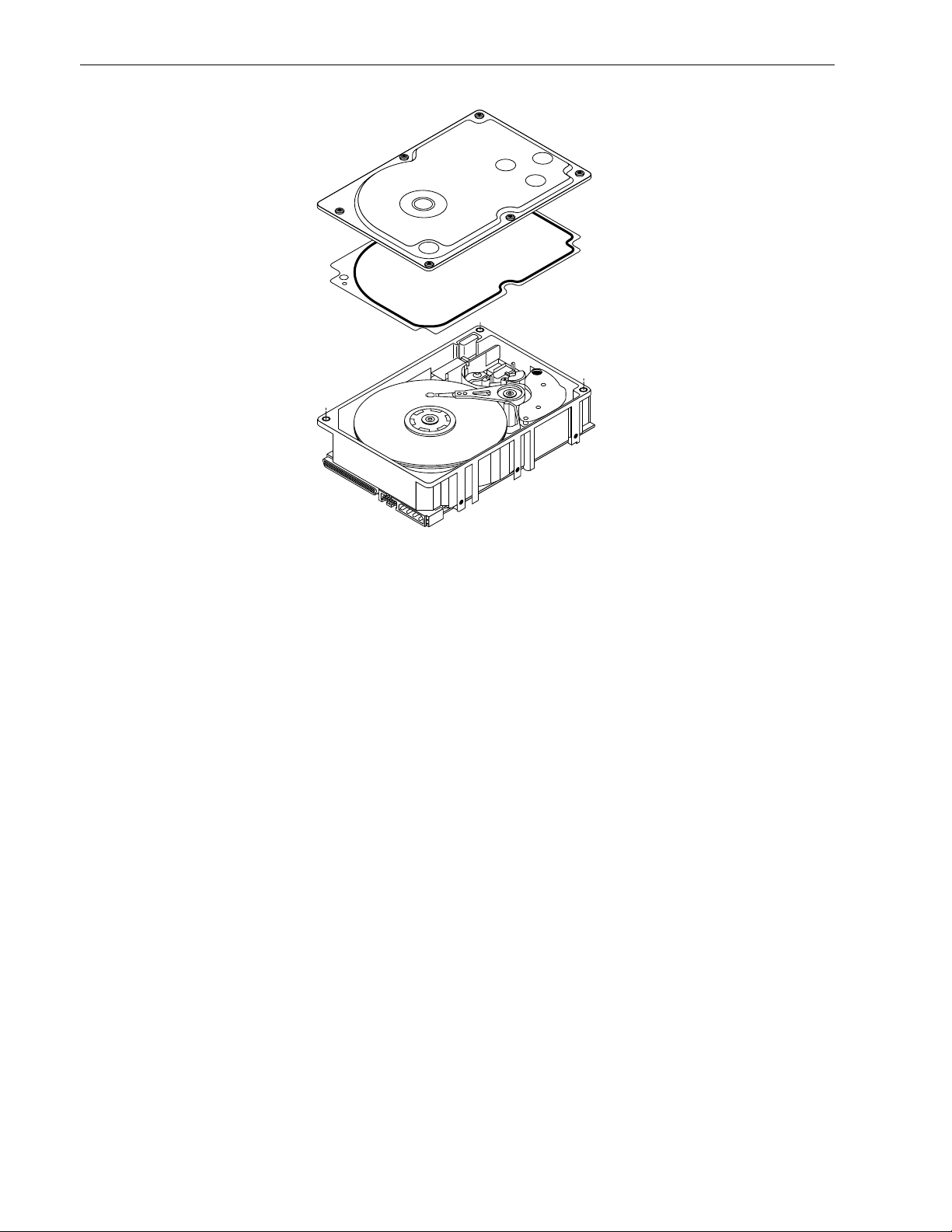
Figure 2. Barracuda 180 family drive. . . . . . . . . . . . . . . . . . . . . . . . . . . . . . . . . . . . . . . . . . . . . . . . . . . . 6
Figure 3. Typical Barracuda 180 family drive +12 V current profile. . . . . . . . . . . . . . . . . . . . . . . . . . . . 22
Figure 4. Typical Barracuda 180 SCSI SE mode +5 V current profile. . . . . . . . . . . . . . . . . . . . . . . . . . 23
Figure 5. Typical Barracuda 180 SCSI LVD mode +5 V current profile. . . . . . . . . . . . . . . . . . . . . . . . . 23
Figure 6. DC current and power vs. input/output operations per second (single-ended mode) . . . . . . 24
Figure 7. DC current and power vs. input/output operations per second (LVD mode) . . . . . . . . . . . . . 24
Figure 8. Location of the HDA temperature check point . . . . . . . . . . . . . . . . . . . . . . . . . . . . . . . . . . . . 25
Figure 9. Recommended mounting . . . . . . . . . . . . . . . . . . . . . . . . . . . . . . . . . . . . . . . . . . . . . . . . . . . . 27
Figure 10. ST1181677LW/LWV mounting configuration dimensions . . . . . . . . . . . . . . . . . . . . . . . . . . . 29
Figure 11. ST1181677LC/LCV mounting configuration dimensions . . . . . . . . . . . . . . . . . . . . . . . . . . . . 30
Figure 12. J6 jumper header . . . . . . . . . . . . . . . . . . . . . . . . . . . . . . . . . . . . . . . . . . . . . . . . . . . . . . . . . . 34
Figure 13. J5 jumper header (on LW/LWV models only). . . . . . . . . . . . . . . . . . . . . . . . . . . . . . . . . . . . . 35
Figure 14. J2 option select header . . . . . . . . . . . . . . . . . . . . . . . . . . . . . . . . . . . . . . . . . . . . . . . . . . . . . 36
Figure 15. Suggested air flow . . . . . . . . . . . . . . . . . . . . . . . . . . . . . . . . . . . . . . . . . . . . . . . . . . . . . . . . . 38
Figure 16. ST1181677LW/LWV drive physical interface (68-pin J1 SCSI I/O connector). . . . . . . . . . . . 50
Figure 17. ST1181677LC/LCV drive physical interface (80-pin J1 SCSI I/O connector) . . . . . . . . . . . . 50
Figure 18. SCSI daisy chain interface cabling for LW/LWV drives . . . . . . . . . . . . . . . . . . . . . . . . . . . . . 53
Figure 19. Nonshielded 68 pin SCSI device connector used on LW/LWV drives . . . . . . . . . . . . . . . . . . 54
Figure 20. Nonshielded 80 pin SCSI “SCA-2” connector, used on LC/LCV drives . . . . . . . . . . . . . . . . . 55
Figure 21. LVD output signals . . . . . . . . . . . . . . . . . . . . . . . . . . . . . . . . . . . . . . . . . . . . . . . . . . . . . . . . . 61
Figure 22. Typical SE-LVD alternative transmitter receiver circuits . . . . . . . . . . . . . . . . . . . . . . . . . . . . 61
Page 10

Page 11
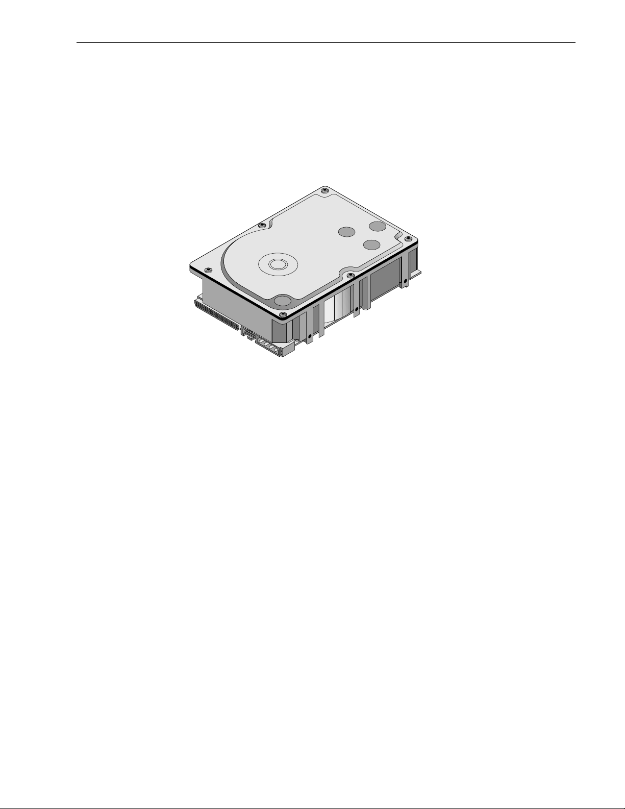
Barracuda 180 Product Manual, Rev. A 1
1.0 Scope
This manual describes Seagate Technology® LLC, Barracuda 180™ disc drives.
Barracuda 180 drives support the small computer system interface as described in the ANSI SCSI SPI-3 inter-
face specifications to the extent descri bed in this manual. The SCSI Interface Product Manual (par t number
75789509) describes general SCSI interface characteristics of this and other families of Seagate drives.
From this point on in this product manual the reference to Barracuda 180 mod els is referred to as “the dr ive”
unless references to individual models are necessary.
Figure 1. Barracuda 180 family drive (ST1181677LW shown)
Page 12

2 Barracuda 180 Product Manual, Rev. A
Page 13

Barracuda 180 Product Manual, Rev. A 3
2.0 Applicable standards and reference documentation
The drive has been developed as a system peripheral to the highest standards of design and construction. The
drive depends upon i ts host equip ment to provide adequ ate power and environment i n order to achieve optimum performance and compli ance with applicable industry and governm ental regulations. Special attention
must be given in the areas of safety, power distribution, shielding, audible noise control, and temperature regulation. In particular, the drive must be secure ly mo unted in order to guarantee the s pec if ied per for ma nc e char acteristics. Mounting by bottom holes must meet the requirements of Section 8.4.
2.1 Standards
The Barracuda 180 family complies with Seagate standards as noted in the appropriate sections of this Manual
and the Seagate SCSI Interface Product Manual.
The Barracuda 180 disc drive is a UL rec ognized component per UL1950 , CSA certifie d to CSA C22.2 No.
950-M89, and VDE certified to VDE 0805 and EN60950.
2.1.1 Electromagnetic compatibility
The drive, as delivered, is designed for system integration and installation into a suitable enclosure prior to use.
As such the drive is suppli ed as a subassembly and is not su bject to Subpar t B of Part 15 of the FCC Rules
and Regulations nor the Radio Interference Regulations of the Canadian Department of Communications.
The design characteristics of the drive serve to minimize radiation when installed in an enclosure that provides
reasonable shielding. As such, the drive is capable of meeting the Class B limits of the FCC Rules and Regulations of the Canadian Department of Communications when properly packaged. However, it is the user’s
responsibility to assure that the drive meets the appropriate EMI req uirements in their syst em. Shielded I/O
cables may be required if the e nclosure does not provide ad equate sh ielding. If the I/O c ables are externa l to
the enclosure, shielded cables should be used, with the shields grounded to the enclosure and to the host controller.
2.1.2 Electromagnetic susceptibility
As a component assembly, the drive is not required to meet any susceptibility per formance requ irements. It is
the responsibility of tho se integrating the dr ive within their sy stem s to perform thos e tests req uired and design
their system to ensu re that equipment operating in the sam e system as the drive or external to the s ystem
does not adversely affect the performance of the drive. See Section 5.1.1 and Table 2, DC power requirements.
2.2 Electromagnetic compliance
Seagate uses an independ ent laboratory to co nfirm compliance to the directives/standard(s) for CE Mark ing
and C-Tick Marking. The drive was tested in a representative system for typical applications. The selected system represents the most popular characteristics for test platforms. The system configurations include:
• Typical current use microprocessors
• 3.5-inch floppy disc drive
• Keyboard
• Monitor/display
• Printer
• External modem
• Mouse
Although the test system wi th this Seag ate mode l co mpl ie s to the dire cti ves/standa rd(s ), we cann ot gua rante e
that all systems will compl y. The computer manufacturer or system integrator must conf irm EMC complia nce
and provide CE Marking and C-Tick Marking for their product.
Electromagnetic compliance for the European Union
If this model has the CE Marki ng it complies with the European Union requirem ents of the Electromagnetic
Compatibility Direc tive 89/336/EEC o f 03 May 1989 as ame nded by Direct ive 92/31/EE C of 28 Ap r il 1992 an d
Directive 93/68/EEC of 22 July 1993.
Page 14

4 Barracuda 180 Product Manual, Rev. A
Australian C-Tick
If this model has the C-Tick Markin g it complies with the Australia/New Zea land Standard A S/NZS3548 199 5
and meets the Electro magnetic Compatibility (EMC) Framework requirements of Australia’s Spectrum Management Agency (SMA).
Korean MIC
If this model has the MIC (Ministry of Information and Communication) Marking it complies with paragraph 1 of
Article 11 of the Electromagnetic Compatibility control Regulation and meets the Electromagnetic Compatibility
(EMC) Framework requirements of the Radio Research Laboratory Ministry of Information and Communication
Republic of Korea.
Tai wan MIC
If this model has two Chinese words meaning “EMC certificat ion” followed by an eigh t digit ide ntificati on number, as a Marking, it complies with Chinese Na tional Standard (CNS) 13438 and meets the Electromagnetic
Compatibility (EMC) Framework requirements of the Taiwanese Bureau of Standa rds, Metrology, and Inspection (BSMI).
2.3 Reference documents
Barracuda 180 Installation Guide Seagate P/N 100109942
Safety and Regulatory Agency Spec ifi catio ns Seagate P/N 75789512
SCSI Interface Product Manual Seagate P/N 75789509
ANSI small computer system interface (SCSI) document numbers:
T10/1143D Enhanced SCSI Parallel Interface (EPI)
T10/1236D Primar y Comm and s-2 (S PC -2 )
T10/996D SCSI Block Commands (SBC)
T10/1157D SCSI Architectural Mode l-2 (S AM - 2)
T10/1302D SPI-3 (SCSI Parallel Interface version 3)
SFF-8046 Specification for 80-pin connector
Package Test Specification Seagate P/N 30190-001 (under 100 lb.)
Package Test Specification Seagate P/N 30191-001 (over 100 lb.)
Specification, Acoustic Test Requirements, and Procedures Seagate P/N 30553-001
In case of conflict between this document and any referenced document, this document takes precedence.
Page 15

Barracuda 180 Product Manual, Rev. A 5
3.0 General description
Barracuda 180 drives combine giant magnetoresistive (GMR) heads, partial response/maximum likelihood
(PRML) read channel el ectroni cs, embedd ed ser vo tech nology, and a wide Ultra160 SCSI interface to provide
high performance, high capaci ty data storage for a variety of syste ms incl uding en ginee ring work statio ns, network servers, mainframes, and supercomputers.
The Ultra160 SCSI i nterface uses negotiated transfer rates. These trans fer rates will occur only if your hos t
adapter supports these data transfer rates and is compa tible with the r eq uir e d hardwa re re qui remen ts of the I/
O circuit type. This drive can al so opera te at S CS I-1 and SCS I-2 dat a transfer rates for backward compatib ility
with non-Ultra/Ultra2/Ultra160 SCSI host adapters.
Table 1 lists the features that differentiate the various Barracuda 180 models.
Table 1: Drive model number vs. differentiating features
Number of I/O
Data buffer
Model number
size I/O circuit type [1]
ST1181677LW 4,096 kbytes Single-ended (SE) and low voltage differential (L VD) 68
ST1181677LWV 16,384 kbytes Single-ended (SE) and low voltage differential (LVD) 68
ST1181677LC 4,096 kbytes Single-ended (SE) and low voltage differential (LVD) 80
connector
pins
ST1181677LCV 16,384 kbytes Single-ended (SE) and low voltage differential (LVD) 80
[1] See Section 9.6 for details and definitions.
The drive records and recovers data on approximately 3.3-inch (84 mm) non-removable discs.
The drive suppor ts the Small Computer System Interface (SCSI) as descr ibed in the ANSI SCSI-2/SCSI-3
interface specifications t o the extent described in this manual (volume 1), which defines the product performance characteris tics of the Barracuda 180 family of dr ives, and the SCSI Interface Product Manual, which
describes the general interface characteristics of this and other families of Seagate SCSI drives.
The drive’s interface supports multiple initiators, disconnect/reconnect, self-configuring host software, and
automatic features that relieve the host from the necessity of knowing the physical characteristics of the targets
(logical block addressing is used).
The head and disc assembly (HDA) is sealed at the factory. Air circulates within the HDA through a nonreplaceable filter to maintain a contamination-free HDA environment.
Refer to Figure 2 for an exploded view of the drive. This exploded view is for information only—nev er di sasse mble the HDA and do not attempt to service items in the se aled enc losure (head s, media, actuator, etc.) as this
requires special facilities. The drive contains no replaceable parts. Opening the HDA voids your warranty.
Barracuda 180 drives use a ded icate d landi ng zone at the in ner most rad ius of th e media to eliminate the possibility of destroying or degrading data by landing in the data zone. The drive automatically goe s to the lan din g
zone when power is removed.
An automatic shipping lock prevents potential damage to the heads and discs that results from movement during shipping and ha ndl ing . T he shi ppi ng lock au toma tic al ly di se nga ges whe n power is applied to the drive and
the head load process begins.
Barracuda 180 drives decode track 0 location data from the servo data embedded on each surface to eliminate
mechanical transducer adjustments and related reliability concerns.
A high-performance actuator assembly with a low-inertia, balanced, patented, straight-ar m design provides
excellent performance with minimal power dissipation.
Page 16
6 Barracuda 180 Product Manual, Rev. A
Figure 2. Barracuda 180 family drive
Page 17

Barracuda 180 Product Manual, Rev. A 7
3.1 Standard features
The Barracuda 180 family has the following standard features:
• Integrated Ultra160 SCSI controller
• Multimode SCSI drivers and receivers—single-ended (SE) and low voltage differential (LVD)
• 16 bit I/O data bus
• Asynchronous and synchronous data transfer protocol (supports Ultra160 transfer rate)
• Firmware downloadable via SCSI interface
• Selectable even byte sector sizes from 512 to 4,096 bytes/sector
• Programmable sector reallocation scheme
• Flawed sector reallocation at format time
• Programmable auto write and read reallocation
• Reallocation of defects on command (post format)
• Enhanced ECC (maximum burst corrections length of 240 bits with a guaranteed burst correction of 233 bits)
• Sealed head and disc assembly
• No preventative maintenance or adjustment required
• Dedicated head landing zone
• Embedded servo design
• Self diagnostics performed when power is applied to the drive
• Zoned bit recording (ZBR)
• Vertical, horizontal, or top down mounting
• Dynamic spindle brake
• 4,096 kbyte data buffer (16,384 kbytes on LWV and LCV models)
• Hot plug compatibility for LC and LCV model drives (Section 9.6.4.2 lists proper host connector needed)
• Supports SCSI bus fairness
3.2 Media characteristics
The media used on the dr ive has a di ameter of a pproximately 3 .3 in ches (8 4 mm). The alumi num substrat e is
coated with a thin film magneti c mat eria l, overcoated with a propr iet ar y prote ctive layer for improved durability
and environmental protection.
3.3 Performance
• Supports industry standard Ultra160 SCSI interface
• Programmable multi-segmentable cache buffer (see Section 3.1)
• 7,200 RPM spindle. Average latency = 4.17 ms
• Command queuing of up to 64 commands
• Background processing of queue
• Supports start and stop commands (spindle stops spinning)
3.4 Reliability
• 1,200,000 hour MTBF
• LSI circuitry
• Balanced low mass rotary voice coil actuator
• Incorporates industry-standard Self-Monitoring, Analysis and Reporting Technology (S.M.A.R.T.)
• Incorporates Drive Self Test (DST) technology
• 5-year warranty
Page 18

8 Barracuda 180 Product Manual, Rev. A
3.5 Unformatted and formatted capacities
Formatted capacity depends on the number of spare reallocation sectors reserved and the number of bytes per
sector. The following table shows the standard OEM model capacities:
Formatted
data block size
512 bytes/sector [1] Unformatted
ST1181677 1522c441h (181.6 GB) [2] 241.9 GB
Notes.
[1] Sector size se lectable at format time. Users having the necessar y equipmen t may modify the data block
size before issuing a format co mmand and obtain different formatted capa cities than those listed. See
Mode Select Command and Format Command in the SCSI Interface Product Manual.
[2] User available capacit y depends on spare r eallocation schem e selected, the number o f data tracks per
sparing zone, and the number of alternate sectors (LBAs) per sparing zone.
3.6 Programmable drive capacity
Using the Mode Sele ct com mand, you can c hange the d r ive’s capacity to something les s than m aximum. Se e
the SCSI Interface Product Manual. Refer to the Parameter list block descriptor number of blocks field. A value
of zero in the number of blocks field indicates that the drive will not change the capacity it is currently formatted
to have. A number in the number of blocks field that is less than the maximum number of LBAs changes the
total drive capacity to the value in the block descriptor numb er of blocks field. A value greater than the m aximum number of LBAs is rounded down to the maximum capacity.
3.7 Factory installed accessories
OEM standard dr ives are ship ped with the Bar racuda 180 In stall ation Gui de, par t numb er 100 109942 and th e
Safety and Regulator y Agency Specifications, part number 75 789512 (unless otherwise specified ). A small
bag of jumper plugs used for the J2, J5, and J6 option select jumper headers are also included with the drive.
3.8 Options (factory instal led)
All customer request ed options are incorporate d during production or packaged at the manufacturin g facility
before shipping. Some of the options available are (not an exhaustive list of possible options):
• Other capacities can be ordered depending on sparing scheme and sector size requested.
• Single unit shipping pack. The drive is norm ally shipped in bulk pa ckaging to provide maximum protec tion
against transit damage. Units shipped individually require additional protection as provided by the single unit
shipping pack. Users planning single unit distribution should specify this option.
• The Bar racuda 180 Installation Guide, par t number 100109942. This guide i s usually included with each
standard OEM drive shipped, but you may order extra copies.
• The Safety and Regulatory Agency Specif ications, part number 757895 12, is usually included with each
standard OEM drive shipped, but you may order extra copies.
3.9 Accessories (user installed)
The following accessories are available. All accessories may be installed in the field.
• Single unit shipping pack.
Page 19

Barracuda 180 Product Manual, Rev. A 9
4.0 Performance characteristics
4.1 Internal drive characteristics (transparent to user)
ST1181677
Drive capacity 181.6 GBytes (formatted, rounded off values)
Read/write heads 24
Bytes/track 406,071 Bytes (average, rounded off values)
Bytes/surface 19,263 Mbytes (unformatted, rounded off values)
Tracks/surface (total) 24,247 Tracks (user accessible)
Tracks/inch 31,200 TPI
Peak bits/inch 490 KBPI
Internal data rate 282-508 Mbits/sec (variable with zone)
Disc rotational speed 7,200 r/min (+
Average rotational latency 4.17 msec
4.2 SCSI performance characteristics (visible to user)
The values given in Section 4.2.1 apply to al l models of the Bar racuda 180 family unless otherwi se specified .
Refer to Section 9.10 and to the SCSI Interface Product Manual for additional timing details.
4.2.1 Access time [5]
Including controller overhead
(without disconnect) [1] [3]
Drive level Drive level
Read Write Read Write
msec msec
Average—Typical [2] 7.6 8.4 7.4 8.2
Single Track—Typical [2] 1.0 1.3 0.8 1.1
Full Stroke—Typical [2] 16.2 17.2 16.0 17.0
0.5%)
Not Including controller overhead
(without disconnect) [1] [3]
4.2.2 Format command execution time (minutes) [1]
ST1181677
Maximum (with verify) 210
Maximum (no verify) 120
4.2.3 Generalized performance characteristics
Minimum sector interleave 1 to 1
Data buffer transfer rate to/from disc media (one 512-byte sector):
Minimum [3]* 25.3 MByte/sec
Average [3] 36.1 MByte/sec
Maximum [3] 47.0 MByte/sec
SCSI interface data transfer rate (asynchronous):
Maximum instantaneous one byte wide 5.0 Mbytes/sec [4]
Maximum instantaneous two bytes wide 10.0 Mbytes/sec [4]
Synchronous formatted transfer rate
Ultra2 SCSI Ultra160 SCSI
In low voltage differential (LVD) interface mode 5.0 to 80 Mbytes/sec 5.0 to 160 Mbytes/sec
Page 20

10 Barracuda 180 Product Manual, Rev. A
Sector Sizes:
Default 512 byte user data blocks
Variable 512 to 4,096 bytes per sector in even number of bytes per sector.
If n (number of bytes per sector) is odd, then n-1 will be used.
Read/write consecutive sectors on a track Yes
Flaw reallocation performance impact (for flaws reallocated at format time using
the spare sectors per sparing zone reallocation scheme.)
Average rotational latency 4.17 msec
Notes for Section 4.2.
[1] Execution time measured fr om receipt of the last byte of the Command Descriptor Blo ck (CDB) to the
request for a Status Byte Tr ansfer to the Initiator (excluding connect/disconnect).
[2] Typical access times are measur ed under nominal c ondition s of temperat ure, voltage, and hor izontal or i-
entation as measured on a representative sample of drives.
[3] Assumes no errors and no sector has been relocated.
[4] Assumes system ability to support the rates listed and no cable loss.
[5] Access time = controller overhead + average seek time.
Access to data = controller overhead + average seek time + latency time.
4.3 Start/stop time
After DC power at no minal voltage h as been appl ied, the d r ive becom es rea dy withi n 30 sec onds if the Mo tor
Start Opti on is disabled (i.e. the motor star ts as soon as the power has bee n applied). If a recoverable error
condition is detected during the start sequence, the drive executes a recovery procedure which may cause the
time to become rea dy to exceed 30 seconds. Dur ing spin up to ready time the dr ive responds to s ome commands over the SCSI interface in less than 1.5 seconds afte r application of power. Stop time is less than 30
seconds from removal of DC power.
If the Motor Star t Option is en abled, the inter nal cont roller accep ts the comm ands list ed in the SCSI In terface
Product Manual less tha n 1.5 s econds after DC power has bee n appl ied. Afte r the Motor Start Command has
been received the d rive becomes ready for nor mal opera tions withi n 30 seco nds typical ly (excluding an error
recovery procedure). The Mo tor Start Comm and can also be used to comm and the drive to stop the spindle
(see SCSI Interface Product Manual).
Negligible
There is no power control switch on the drive.
4.4 Prefetch/multi-segmented cache control
The drive provides prefetch (read look-ahead) and multi-segmented cache control algorithms that in many
cases can enhanc e system perfor manc e. “The term “cache” refers to the drive buffer storage space when it is
used in cache operations. To select prefetch and cache features, the host sends the Mode Select com mand
with the proper values in the applicable bytes in Mode Page 08h (see SCSI Interface Product Manual). Prefetch
and cache operations ar e independent features from the sta ndpoint that each is ena bled and disabled independently using the Mode Select command. However, in actual operation, the pr efetch feature overlaps ca ch e
operation somewhat as is noted in Section 4.5.1 and 4.5.2.
All default cache and prefetch Mode pa rameter values (Mode Page 08h) for standard OEM versions of this
drive family are provided in Table 7.
4.5 Cache operation
In general, 3,600 kbytes (14,399 kbytes of the 16, 384 kbytes on LWV and LCV models) of the 4,096 kbytes of
physical buffer space in the drive can be used as storage space for cache operations. The buffer can be divided
into logical segm ents (Mode Sele ct Page 08h, byte 13) from whic h data is read and to which da ta is written .
The drive supports a maximum of 64 cache segments and maintains a table of logical block disk medium
addresses of the data stored in each segment of the buffer. If cache operation is enabled (RCD bit = 0 in Mode
Page 08h, byte 2, bit 0. See SCSI Interface Product Manual ), data requested by the host with a Read command is retrieved from the buffer (if it is there) before any disc access is initia ted. If cache operation is not
Page 21

Barracuda 180 Product Manual, Rev. A 11
enabled, the buffer (still segmented with required numb er of segments ) is still use d, but only as circula r buffer
segments during d isc medium read op erations (disregard ing Prefetch operation for the moment) . That is, the
drive does not check in the buffer segments for the requested read data, but goes di rectly to the medium to
retrieve it. The retrieved data merely passes thr ou gh some buffer segment on the way to the host. On a cache
miss, all data transfers to the host are in accordance with buffer-full ratio rules. On a cache hit, the drive ignores
the buffer-full ratio rules. See explanations as sociated with Mode p age 02h (disconne ct/reconnect contr ol) in
the SCSI Interface Product Manual.
The following is a simplified description of a read operation with cache operation enabled:
Case A -
1. Drive transfers to the initiator the first LB reque ste d plus all subsequent contiguous LBs that are alr ea dy in
2. When the requested LB is reached that is not in any cache segment, the drive fetches it and any remaining
3. If the prefetch feature is enabled, refer to Section 4.5.2 for operation from this point.
Case B -
1. The drive fetches the requested LBs from the disc and transfers them into a segment, and from there to the
2. If the prefetch feature is enabled, refer to Section 4.5.2 for operation from this point.
Each buffer segment is a self-contain ed circular storage area (wrap-around oc curs), the leng th of which is an
integer number of disc medium sectors. The wrap-around capability of the individual segments greatly
enhances the buffer’s overall performance as cac he s torage, a llowing a wi de range of u se r se lec table co nfi gurations, including their u se in the prefetch operation (if enabled) even when cache operation is dis abled (see
Section 4.5.2). The number of segments is set dynamically by the drive and cannot be set by the host. The size
in kbytes of each segment is not reported by the Mode Sense command page 08h, bytes 14 and 15. The value
0XFFFF is always reported. If a size specification is sent by the host in a Mode Select command (bytes 14 and
15) no new segment size is set up by the drive, and if the STRICT bit in Mode pa ge 00 h (byte 2, bit 1) is se t to
one, the drive responds as it does for any attempt to change unc hangeable parameters (see SCSI Interface
Product Manual). The dr ive supports operation of any integer numbe r of se gme nts from 1 to 6 4. The default is
three segments.
A Read command is received and the first logical block (LB) is already in cache:
the cache. This data may be in multiple segments.
requested LBs from the disc an d puts them in a s egment of the cache. The dr ive transfers the remainin g
requested LBs from the ca che to t he host in accorda nce with the disconn ect/r econn ect speci fication mentioned above.
A Read command requests data, the first LB of which is not in any segment of the cache:
host in accordance with the disconnect/reconnect specification referred to in case A.
4.5.1 Caching write data
Write caching is a wr ite operation that uses the drive buffer storage area where the data to be writte n to the
medium is stored in one or more segments while the drive performs the write command.
If read caching is enabled (RCD=0), data written to th e medium is retained in the cache for future read cache
hits. The same buffer space and segmentation is used as set up for read functions. The buffer segmentation
scheme is set up or changed independe ntly, having nothing to do with the state o f the RCD bi t. When a write
command is issued, if RCD=0, the cache is first ch ecked to see if any logical blocks that are to be written are
already stored in the cac he from a previous read or write comman d. If there are, the respective cache segments are cleared. The new data is cached for subsequent Read commands.
If the number of wri te data lo gical blocks exceeds t he size of the segment b eing w ritten i nto, when the end of
the segment is reached, the data is written into the beginning of the same cache segment, overwriting the data
that was written there at the beginning of the operation. However , the drive does not overwrite data that has not
yet been written to the medium.
If write caching is enabled (WCE=1), the drive may return GOOD status on a write command after the data has
been transferred into the cache, but before the data has been written to th e medium. If an error occurs while
writing the data to the medium, and GOOD status has already been returned, a deferred error will occur.
The Synchronize Cache command may be used to force the drive to write all cached write data to the medium.
Upon completion of a Synchronize Cache command, all data received from previous write commands will have
been written to the medium.
Page 22

12 Barracuda 180 Product Manual, Rev. A
Tables 7 show Mode default settings for the drives.
4.5.2 Prefetch operation
If the Prefetch feature is enabled, data in conti guous lo gical blocks on the disc i mmedia tely b eyond that which
was requested by a Read comman d can be retri eved and stored in the buffer for immediate transfer from the
buffer to the host on subsequent Read commands that request those logical blocks (this is true even if cache
operation is disabled). Though th e prefetch operation us es the buffer as a cache, findin g the r equ es ted data i n
the buffer is a prefetch hit, not a cache operation hit. Prefetch is enabled using Mode Select page 08h, byte 12,
bit 5 (Disable Read Ahead - DRA bit). DRA bit = 0 enables prefetch. Since data that is prefetched replaces data
already in some buffer segment(s), the host can limit the am ount of prefetch data to optimize s ystem performance. The max prefetch field (bytes 8 and 9) limits the amount of prefetch. The drive does not use the
Prefetch Ceiling field (bytes 10 and 11).
During a prefetch operation, the dri ve crosses a cyl inder bounda r y to fetch more data o nly if the Discontinuity
(DISC) bit is set to one in bit 4 of byte 2 of Mode parameters page 08h.
Whenever prefetch (read look-ahead) is enabled ( enabled by DRA = 0), it opera tes und er the co ntrol of ARLA
(Adaptive Read Look-Ahead). If the host uses software interleave, ARLA enables prefetch of contiguous blocks
from the disc when it sense s that a prefetch hit will l ikely occur, even if two consecutive read operations were
not for physically contiguous blocks of data (e.g. “software interleave”). ARLA disables prefetch when it decides
that a prefetch hit will not likely occur. If the host is not using softwa re interleave, and if two sequential read
operations are not for contiguous blocks of data , ARL A dis ables pre fetch, but as long as s equ enti al read oper ations request contiguous blocks of data, ARLA keeps prefetch enabled.
Page 23

Barracuda 180 Product Manual, Rev. A 13
5.0 Reliability specifications
The following reliability spe cifications assume correct hos t/drive operational interface, including all interface
timings, power supply voltages, environmental requirements and drive mounting constraints (see Section 8.4).
Seek Errors
Less than 10 in 10
Read Error Rates [1]
Recovered Data Less than 10 errors in 10
Unrecovered Data Less than 1 sector in 10
Miscorrected Data Less than 1 sector in 10
MTBF 1,200,000 hours
Service Life 5 years
Preventive Maintenance None required
Note.
[1] Error rate specified with automatic retries and data correction with ECC enabled and all flaws reallocated.
5.1 Error rates
The error rates stated in this specification assume the following:
• The drive is operated per this specification using DC power as defined in this manual (see Section 6.2).
• The drive has been formatted with the SCSI Format command.
• Errors caused by media d efects or hos t system failures are exclude d from er ror rate comp utat ions. Refer to
Section 3.2, “Media Characteristics.”
• Random data is used.
8
seeks
12
bits transferred (OEM default settings)
15
bits transferred (OEM default settings)
21
bits transferred
5.1.1 Environmental interference
When evaluating system operation under conditions of Electromagnetic Interference (EMI), the performance of
the drive within the system is considered acceptable if the drive does not generate an unrecoverable condition.
An unrecoverable error, or unrecoverable condition, is defined as one that:
• Is not detected and corrected by the drive itself;
• Is not capable of being detected from the error or fault status provided through the drive or SCSI interface; or
• Is not capable of being recovered by normal dr ive or sys tem rec overy pro cedur es wit hou t opera tor inte rven-
tion.
5.1.2 Read errors
Before determination or measurement of read error rates:
• The data to be used for measurement of rea d error rates must be ver ified as being wr itten correc tly on the
media.
• All media defect induced errors must be excluded from error rate calculations.
5.1.3 Write errors
Write errors can occur as a result of media defects, environmental interference, or equipment malfunction.
Therefore, write errors are not predictable as a function of the number of bits passed.
If an unrecoverable write error occurs beca use of a n equipm ent mal functi on in the dr ive, the error is classi fied
as a failure affecting MTBF. Unrecoverable write errors are those which cannot be corrected within two
attempts at writing the record with a read verify after each attempt (excluding media defects).
5.1.4 Seek errors
A seek error is de fin ed as a failure o f t he drive to position the heads to t he add re ss ed track. Th ere sh all b e no
more than ten recoverable seek errors in 10
8
physical seek operations. After detecting an init ia l se ek err or, the
drive automatically per forms an error recover y process. If the error r ecovery process fails, a seek posi tioning
error (15h) is repor ted wit h a Medium err or (3h) or Har dware error (4h) repo rt ed in the Sense Key. This is an
Page 24

14 Barracuda 180 Product Manual, Rev. A
unrecoverable seek error. Unrecoverable seek errors are classified as failures for MTBF calculatio ns. Refer to
the SCSI Interface Product Manual for Request Sense information.
5.2 Reliability and service
You can enhance the reliability of Barracuda 180 disc drives by ensuring that the drive receives adequate cooling. Section 6.0 pr ovides temperature meas urements and other information that you can use to enhanc e the
service life of the drive. Section 8.3 provides recommended air-flow information.
5.2.1 Mean time between failure
The production disc drive achieves an MTBF of 1,200,000 hours when operated in an environment that
ensures the case temperatures spec ified in Sectio n 6.4.1 are not exceeded. Shor t-ter m excursions up to th e
specification limits of the operating environment will not affect MTBF performance. Continual or sustained
operation at case temperatures above the values specified in Section 6.4.1 may degrade product reliability.
The MTBF target is specified as device power-on hours (POH) for all drives in service per failure.
MTBF per measurement period =
Estimated power-on operating hours in the per i od
__
Number of drive failures in the period
Estimated power-on operation hours means power-up hours per disc drive times the total number of disc drives
in servic e. Each disc dr ive must have accumulated at least ni ne months of op eration. Data is c alculated on a
rolling average base for a minimum period of six months.
MTBF is based on the following assumptions:
• 8,760 power-on hours per year.
• 250 average on/off cycles per year.
• Operations at nominal voltages.
• Systems will provide adequate cooling to ensure the case temperatures specified in Section 6.4.1 are not
exceeded.
Drive failure means any stoppage or substandard performance caused by drive malfunction.
A S.M.A.R.T. predictive failure indicates that the dr ive is dete riora ting to an imm inent failure and is consi dere d
an MTBF hit.
5.2.2 Field failure rate vs. time
The expected field failure rate is listed below. Drive utilization will vary. An estimated range of utilization is:
• 720 power-on hours (POH) per month.
• 250 on/off cycles per year.
• Read/seek/write operation 90% of power-on hours.
• Systems will provide adequate cooling to ensure the case temperatures specified in Section 6.4.1 are not
exceeded.
Month 1 2,500 PPM
Month 2 1,600 PPM
Month 3 1,200 PPM
Month 4 1,000 PPM
Month 5 890 PPM
Month 6 840 PPM
Month 7 805 PPM
Failure rate is calculated as follows:
• No system-induced failures are counted
• Based on 1,200,000 MTBF and 720 power-on hours per month
• Month 1’s rate includes a 300 PPM installation failure
Page 25

Barracuda 180 Product Manual, Rev. A 15
5.2.3 Preventive maintenance
No preventive maintenance is required.
5.2.4 Service life
The useful ser v ic e life of the dr i ve is five years. Depot repa ir or re pla ce men t of major part s i s permitted during
the lifetime (see Section 5.2.5).
5.2.5 Service philosophy
Special equipmen t is requir ed to repair the drive HDA. In order to achi eve the above service life, repairs must
be performed only at a proper ly equip ped and staffed ser vice and repair facility. Troubleshooting and repa ir of
PCBs in the field i s not recommended, be cause of the extensive diagnostic eq uipment required for effective
servicing. Also, there are no spare parts available for this drive. Drive warranty is voided if the HDA is opened.
5.2.6 Service tools
No special tools are requi red for site instal lat ion or recomm ended for site maintenance. Refer to Section 5.2.5.
The depot repair philosophy of the drive precludes the necessity for special tools. Field repair of the drive is not
practical since there are no user purchasable parts in the drive.
5.2.7 Hot plugging Barracuda 180 disc drives
The ANSI SPI-3 (T10 /1302D) documen t defines the physical requi rements for removal and inser tion of SCS I
devices on the SCSI bus. Four cases are addressed. The cases are differentiated by the state of the SCSI bus
when the removal or insertion occurs.
Case 1 - All bus devices powered off during removal or insertion
Case 2 - RST signal asserted continuously during removal or insertion
Case 3 - Current I/O processes not allowed during insertion or removal
Case 4 - Current I/O process allowed during insertion or removal, except on the device being changed
Seagate Barracuda 18 0 disc dr ives support all four hot plugg ing cas es. Provisio n sho uld be made by the sy stem such that a device being inser ted makes power and ground connections prior to the connection of any
device signal contact to the bus. A device being removed should maintain power and ground connections after
the disconnection of any device signal contact from the bus (see SFF-8046, SCA-2 specification).
It is the responsibility of the systems integrator to assure that no hazards from temperature, energy, voltage, or
ESD potential are presented during the hot connect/disconnect operation.
All I/O processes for the SCS I d evice being i ns erted or removed should be qui es c ent. Al l S CSI devices on the
bus should have receivers that conform to the SPI-3 standard.
If the device being hot plugged uses single-ended (SE) drivers and the bus is currently operating in low voltage
differential (LVD) mode, then all I/O processes for all devices on the bus must be completed , and the bus quiesced before attempting to hot plug the drive. Following the insertion o f the newly installed device, the SCSI
host adapter must issue a Bus Reset, followed by a synchronous transfer negot iation. Failure to perform the
SCSI Bus Reset could result in erroneous bus operations.
The SCSI bus termination and termination power source must be external to the device being inser ted or
removed.
End users should not mix devices with high voltage differential (H VD) drivers and receivers and devices wit h
SE, LVD, or multimode drivers and receivers on the s ame SCSI bus since the commo n mode voltages in the
HVD environment may not be controlled to safe levels for SE and LVD devices (see ANSI SPI-3).
The disc drive spindle must co me to a complete st op prior to comple tely removing the dr ive from the cabinet
chassis. Use of the Stop Spin dle co mmand o r partial withdrawal of the dr ive, enough to be dis conn ected f rom
the power source, prior to removal are methods for insuring that this requirement is met. During drive insertion,
care should be taken to avoid exceeding the limits stated in Section 6.4.4, “Shock and vibration” in this manual.
Page 26

16 Barracuda 180 Product Manual, Rev. A
5.2.8 S.M.A.R.T.
S.M.A.R.T. is an acronym for Self-Monitori ng Analys is and Rep or ting Technology. This technology is intended
to recognize conditions that indi cate a dri ve failure and is designed to provide suff icient war ning of a failure to
allow data back-up before an actual failure occurs.
Note.
The firmware will monitor specific attributes for degradation over time but cannot predict instantaneous
drive failures.
Each attribute ha s bee n s el ec ted to mo nit or a sp ec ifi c s et of failure c ond itio n s in the operating performance o f
the drive, and the thresholds are optimized to minimize “false” and “failed” predictions.
Controlling S.M.A.R.T.
The operating mode of S.M.A.R.T. is controlled by the DEXCPT bit and the PERF bi t of the “Informational
Exceptions Control Mode Page” (1Ch). Th e DEXCPT bit is us ed to enable or disable the S.M.A.R.T. process.
Setting the DEXCPT bit will disable all S.M.A.R.T. functions. When enabled, S.M.A.R.T. will collect on-line data
as the drive performs nor m al re ad/wr ite operatio ns. When t he PER F bit is set, th e dr ive is consi dered to be in
“On-line Mode Only” and will not perform off-line functions.
The process of measuring off-line attributes and saving data can be forced by the Rezero Unit command. Forcing S.M.A.R.T. will reset the timer so that the next scheduled interrupt will be two hours.
The drive can be interrogated by the host to determine the time remaining before the next scheduled measurement and data loggi ng process will oc cur. This is accomplished by a log sense command to log page 0x3E .
The purpose is to allow the customer to control when S.M.A.R.T. interruptions occur. As described above, forcing S.M.A.R.T by the Rezero Unit command will reset the timer.
Performance impact
S.M.A.R.T. attribute data will be saved to the disc for the purpose of recreating the events that caused a predictive failure. The drive will measure and save parameters once every two hours subject to an idle per iod on the
SCSI bus. The process of m easuring off-line attr ibute data and saving data to th e disc is u ninterrup table and
the maximum delay is summarized below:
Maximum processing delay
On-line only delay Fully enabled delay
DEXCPT = 0, PERF = 1 DEXCPT = 0, PERF = 0
S.M.A.R.T. delay times 50 milliseconds 300 milliseconds
Reporting control
Reporting i s controlled in the Informational Excep tions Control Page (1Ch). Subj ect to the repor ting method,
the firmware will is su e a 01- 5D0 0 s ense c od e to the hos t. T h e err or c ode is pr eserved through bus resets and
power cycles.
Determining rate
S.M.A.R.T. monitors the rate at which errors occur and s ignals a pred ictive failure if the rate of degraded er ror
rate increases to an una cc ept able level. To determine rate, error events are logged and compared to the number of total operations for a given attr ibute. The inter val defines the number of operations over which to m easure the rate. The counter that keeps track of the c urrent number of operations is referred to as the I nterval
Counter.
S.M.A.R.T. measures error rate, hence for each attr ibute the occurrence of an error is recorded. A counter
keeps track of the number of errors for the current interval. This counter is referred to as the Failure Counter.
Error rate is simply the number of errors per ope ration. The algorithm that S.M.A.R.T. uses to record rates of
error is to set thresholds for the number of errors and the interval. If the number of errors exceeds the threshold
before the interval expires, then the error rate is cons idered to be u nacceptable. If the numbe r of errors d oes
not exceed the threshold before the interval expires, then the error rate is considered to be acceptable. In either
case, the interval and failure counters are reset and the process starts over.
Page 27

Barracuda 180 Product Manual, Rev. A 17
Predictive failures
S.M.A.R.T. signals predictive failures when the drive is performing unaccep tably for a period o f time. The f ir mware keeps a running count of the number of times the error rate for each attribute is unacceptable. To accomplish this, a counte r is incremen ted whenever the error rate is una cceptable and de cremented ( not to exceed
zero) whenever the error rate is acceptable. Should the counter continually be incremented such that it reaches
the predictive threshold, a predictive failure is signaled. This counter is referred to as the Failure History
Counter. There is a separate Failure History Counter for each attribute.
5.2.9 Drive Self Test (DST)
Drive Self Test (DST) is a tech nology designed to recognize d rive fault conditions that qu alify the drive as a
failed unit. DST validates the functionality of the drive at a system level.
There are two test coverage options implemented in DST:
1. extended test
2. short test
The most thorough option is the extended test that per forms various test s on the d r i ve and scans every logic al
block address (LBA) of the dr ive. The short test is ti me-restricted an d limited in length —it does not scan the
entire media surface, but does some fundamental tests and scans portions of the media.
If DST encounters an er ror during either of these t ests, it reports a fault conditi on. If the drive fails the test,
remove it from service and return it to Seagate for service.
5.2.9.1 DST Failure Definition
The drive will present a “diagnostic failed” condition throu gh the self-tests resu lts value of the diagnostic log
page if a functional failure is enc ountered during D ST. The channel and ser vo parameter s are not mod ified to
test the drive more stringently, and the number of retries are not reduced. All retries and recovery processes
are enabled during the test. If data is recoverable, no failure condition will be reported regardless of the number
of retries required to recover the data.
The following conditions are considered DST failure conditions:
• Seek error after retries are exhausted
• Track-follow error after retries are exhausted
• Read error after retries are exhausted
• Write error after retries are exhausted.
Recovered errors will not be reported as diagnostic failures.
5.2.9.2 Implementation
This section provides all of the information necessary to implement the DST function on this drive.
5.2.9.2.1 State of the drive prior to testing
The drive must be in a ready state before issuing the Send Diagnostic c ommand. There are multi ple reasons
why a drive may not be ready, some of which ar e valid condi tio ns, and not err or s. For example, a drive may be
in process of doing a format, or another DST. It is the responsibility of the host application to determine the “not
ready” cause.
While not technically part of DST, a Not Ready condition also qualifies the drive to be returned to Seagate as a
failed drive.
A Drive Not Ready condition is reported by the drive under the following conditions:
• Motor will not spin
• Motor will not lock to speed
• Servo will not lock on track
• Drive cannot read configuration tables from the disc
In these conditions, the drive responds to a Test Unit Ready command with an 02/04/00 or 02/04/03 code.
Page 28

18 Barracuda 180 Product Manual, Rev. A
5.2.9.2.2 Invoking DST
To invoke DST, submit the Send D iagnosti c comma nd with the appropr iate Func tion Code (001b for the sho r t
test or 010b for the extended test) in bytes 1, bits 5, 6, and 7. Refer to the Seagate SCSI Interface Product
Manual, Volume 2, part number 75789509 for additional information about invoking DST.
5.2.9.2.3 Short and extended tests
The short and extended test options are described in the following two subsections.
Each test consis ts o f thre e seg men ts: an el ec tr ic al tes t segment, a servo test segme nt, an d a re a d/verify s can
segment.
Short test (Function Code: 001b)
The purpos e o f t he sho rt test is to p rovide a t ime -lim ited test that tests as much o f th e d r ive as pos sible wi thin
120 seconds. The shor t test does not scan the e ntire media surface, but does some fundamental te sts and
scans portions of the media. A complete read/verify scan is not performed and only factual failures will report a
fault condition. This option provides a quick confidence test of the drive.
Extended test (Function Code: 010b)
The objective of the extended test option is to empirically test critical drive components. For example, the seek
tests and on-track operations test the posi ti oni ng me ch ani sm . The r ead operat ion test s the rea d hea d ele men t
and the media su rface. The write elem ent is tested through read/wr ite/read operations. The integrity o f the
media is checked through a read/verify scan of the m edia. Mo tor functio nality is tested by default as a pa r t of
these tests.
The anticipated length of the Extended test is reported through the Control Mode page.
5.2.9.2.4 Log page entr ies
When the drive begins DST, it creates a new entry in the Self- tes t Re su lts Lo g pa ge. The new en try is created
by inserting a new self-test parameter block at the beginning of the self-test results log parameter section of the
log page. Existing data will be moved to make room for the new parameter block. The drive reports 20 parameter blocks in the log page. If there are mor e than 20 pa rameter blocks, the least r ecen t pa rame ter block will b e
deleted. The new parameter block will be initialized as follows:
1. The Function Code field is set to the same value as sent in the DST command
2. The Self-Test Results Value field is set to Fh
3. The drive will store the log page to non-volatile memory
After a self-test is complete or has been aborted, the drive updates the Self-Test Results Value field in its Self-
Test Results Log page in non-volatile memory. The host may use Log Sense to r ead the re su lts fr om up to th e
last 20 self-tests performed by the drive. The self-test results value is a 4-bit field that reports the results of the
test. If the field is zero, the drive passed with no errors detected by the DST. If the field is not zero, the test
failed for the reason reported in the field.
The drive will repor t the failure condition and LBA (if appl icable) in the Self-test Results L og parameter. The
Sense key, ASC, ASCQ, and FRU are used to report the failure condition.
5.2.9.2.5 Abort
There are several ways to abort a diagnostic. You can use a SCSI Bus Res et or a B us Device Res et me ss ag e
to abort the diagnostic.
You ca n abor t a DST executing in background mode by using the abo r t code in the DST Function Code field.
This will cause a 01 (self-test abor ted by the appli cation client) code to appear in the sel f-test results values
log. All other abort mechanisms will be reported as a 02 (self-test routine was interrupted by a reset condition).
5.2.10 Product warranty
Beginning on the date of shipment to customer and continuing for a period of five years, Seagate warrants that
each product (including components and subassemblies) or spare part that fails to function properly under normal use due to defect in mater ials on work mans hip or du e to nonc onform ance t o the app lica ble specific ations
Page 29

Barracuda 180 Product Manual, Rev. A 19
will be repaired or replaced, at Seagate’s option an d at no ch ar ge to c ustomer, if returned by customer at cu stomer’s expense to Seagate’s designated facility in accordance wi th Seagate’s warranty procedure. Seagate
will pay for transporting th e repair or replacement it em to customer. For more detailed warranty information
refer to the Standard terms and conditions of Purchase for Seagate products.
Shipping
When transpor ting or shipping a dr ive, a Seagate approved container must be used. Keep your origina l box.
They are easily identifie d by the Seagate-approved package label. Ship ping a drive in a non-app roved container voids the drive warranty.
Seagate repair centers may refuse receip t of compon ents imp roper ly pa ckaged or obviously damaged in transit. Contact your Authorized Seaga te Dis tr ibutor to pur chase addition al boxes. Seagate recommends ship ping
by an air-ride carrier experienced in handling computer equipment.
Product repair and return information
Seagate customer se rvice centers are the only facilities author ized to service Seagate drives. Seagate does
not sanction any third-par ty repair facilities. Any unauthorized repai r or tampering with the factory- seal voids
the warranty.
Page 30

20 Barracuda 180 Product Manual, Rev. A
Page 31

Barracuda 180 Product Manual, Rev. A 21
6.0 Physical/electrical specifications
This section provides information relating to the drive’s physical and electrical characteristics.
6.1 AC power requirements
None.
6.2 DC power requirements
The voltage and current requirements for a single drive are shown in the following table. Values indicated apply
at the drive power connector. The table shows current values in Amperes.
Table 2: DC power requirements
ST1181677
Notes
SE mode LVD mode
Voltage +5V +12 V +5V +12 V
Regulation [5] ±5% ±5%[2] ±5% ±5%[2]
Average idle current DCX
[1] 0.67 0.55 0.74 0.55
Maximum starting current
(peak DC) DC
(peak AC) AC
[3]
[3]
0.71
0.89
1.32
2.38
0.78
0.99
1.32
2.38
Delayed motor start (max) DC [1][4] 0.56 0.03 0.63 0.03
Peak operating current
DCX
Maximum DC
Maximum (peak) DC
[1][6]
[1]
0.70
0.71
1.25
0.81
0.91
2.25
0.81
0.83
1.52
0.81
0.91
2.25
[1] Measured with average reading DC ammeter or equi valent sampl ing scope. Insta ntaneou s cur rent pea ks
will exceed these values. Power supply at nominal voltage. N = 6, 22 Degrees C ambient.
[2] For +12 V, a –10% tolerance is permissible dur ing initial star t of spindle, and must return to ±5% b efore
7,200 rp m is reached. The ±5 % must be maintained after the drive signifi es that its power-up seque nce
has been completed and that the drive is able to accept selection by the host initiator.
[3] See +12 V current profile in Figu re 3.
[4] This co ndition occurs when the Mo tor Star t Opti on is enabled an d the dr ive has not yet received a Star t
Motor command.
[5] See Section 6.2.1 “Conducted Noise Immunity.” Specified voltage tolerance i s inclusive of ripple, noise,
and transient response.
[6] Operating cond ition is defined as random 8 block reads at 71 I/Os per second. Current and power speci-
fied at nominal voltages. Decreasi ng +5 volt supply by 5% increases 5 volt current by 2.9%. Dec reasing
+12 volt supply by 5% increases +12 volt current by 2.4%.
[7] During idle, the drive heads are r elocated every 60 seconds to a random location withi n the band from
track zero to one-fourth of maximum track.
General Notes from Table 2:
1. Minimum current loading for each supply voltage is not less than 1.8% of the ma ximum operating curren t
shown.
2. The +5 and +12 volt supplies shall employ separate ground returns.
3. Where power is provided to multiple drives from a common supply, careful consideration for individual drive
power requirements should be noted. Where multiple units are powered on simultaneously, the peak starting current must be available to each device.
4. Parameters, other than spindle start, are measured after a 10-minute warm up.
5. No terminator power.
Page 32

22 Barracuda 180 Product Manual, Rev. A
6.2.1 Conducted noise immunity
Noise is specified as a periodi c and random distribution of frequencie s covering a band from DC to 10 MHz.
Maximum allowed noise values given below are peak to peak measurements and apply at the drive power connector.
+5 V = 150 mV pp from 0 to 100 kHz and 100 mV pp from 100 kHz to 10 MHz
+12 V = 150 mV pp from 0 to 100 kHz and 100 mV pp from 100 kHz to 10 MHz
6.2.2 Power sequencing
The drive does not requir e power sequencing. T he drive protects aga inst inadver tent wr iting dur ing power-up
and down. Daisy-chain operat ion requires that power be maintained on the SCSI bus ter minator to ensure
proper termination of the peripheral I/O cables. To automatically delay motor start based on the target ID (SCSI
ID) enable the Delay Motor Star t option and disable the Enable Motor Star t option on the J2 conn ector. See
Section 8.1 for pin selection information. To delay the motor until the dri ve receives a Start Unit command,
enable the Enable Remote Motor Start option on the J2 connector.
6.2.3 12 V - Current profile
Figure 3 identifies the drive +12 V current profile. The current during the various times is as shown:
T0 - Power is applied to the drive.
T1 - Controller self tests are performed.
T2 - Spindle begins to accelerate under current limiting after performing drive internal
diagnostics. See Note 1 of Table 2.
T3 - The spindle is up to speed and the head-arm restraint is unlocked.
T4 - The adaptive servo calibration sequence is performed.
T5 - Calibration is complete and drive is ready for reading and writing.
Note.
All times and currents are typical. See Table 2 for maximum current requirements.
+12 Volt Current during spindle start – Typical Amperes
Peak AC Envelope
3.0
A
2.0
1.0
0.0
T0 T1 T3 T4
T2
Peak DC
0.0 2 4 6 8 10 12 14 16
Seconds
Figure 3. Typical Barracuda 180 family drive +12 V current profile
Page 33

Barracuda 180 Product Manual, Rev. A 23
+5 Volt Current during spindle start (single ended) – Typical Amperes
2.0
A
1.5
1.0
0.5
T1 T2 T4T0 T3 T5
0.0 4 8 12 16 20 24 28 32
Seconds
Figure 4. Typical Barracuda 180 SCSI SE mode +5 V current profile
+5 Volt Current during spindle start (LVD) – Typical Amperes
AC Component
Nominal (average) DC curve
2.0
A
1.5
1.0
0.5
T2T1T0 T3 T4 T5
0.0 4 8 12 16 20 24 28 32
Seconds
Figure 5. Typical Barracuda 180 SCSI LVD mode +5 V current profile
AC Component
Nominal (average) DC curve
Page 34

24 Barracuda 180 Product Manual, Rev. A
6.3 Power dissipation
For drives using single-ended int erface circuits, typical power dissipation under idle cond itions is 9.95 watts
(33.98 BTUs per hour).
For drives using low voltage differential interface circuits, typical power dissipation under idle conditions is 10.3
watts (35.18 BTUs per hour).
To obtain operating power for typical random read operations, refer to the following two I/O rate curves (see figures 6 and 7). L ocate the ty pical I/O rate for a dr ive in your system on the ho rizontal axis and read th e corresponding +5 volt c urrent, +12 volts curre nt, and total watts on the vertical ax is. To calculate BTUs per hour,
multiply watts by 3.4123.
1.800
5V A
1.600
1.400
12V A
Watts
1.200
1.000
Amperes
0.800
0.600
0.400
0 50 100
I/Os per Second
Figure 6. DC current and power vs. input/output operations per second (single-ended mode)
1.800
1.600
1.400
1.200
150 200
17
15
Watts
13
11
17
5V A
12V A
Watts
1.000
Amperes
0.800
0.600
0.400
0 50 100
I/Os per Second
Figure 7. DC current and power vs. input/output operations per second (LVD mode)
150 200
15
Watts
13
11
Page 35

Barracuda 180 Product Manual, Rev. A 25
6.4 Environmental limits
Temperature and humidity values experienced by the d rive must be such that condensati on doe s not occur on
any drive part. A ltitude and atmospher ic pressure specifica tions are referenced to a standa rd day at 58.7°F
(14.8°C). Maximum wet bulb temperature is 82°F (28°C).
6.4.1 Temperature
a. Operating
With cooling designed to maintain the case temperatur e, the drive meets all specificati ons over a 41°F to
122°F (5°C to 50°C) drive ambient temperature range with a maximum temperature gradient of 36°F (20°C)
per hour. The enclosure for the drive sh ould b e d esign ed su ch that the temperatures are no t exceeded . Air
flow may be needed to achieve these temperature values (see Section 8.3). Operation at temperatures
above these values may adversely affect the drives ability to meet specifications.
The MTBF specification for the drive is based on operating in an environment th at ensures that the case
temperatures are not exceeded. Occasio nal excursions to drive ambient temperatures of 122°F (50°C) or
41°F (5°C) may occur without impact to specified MTBF. Air flow may be needed to achieve these temperatures. Continual or sust ained operatio n at c ase te mperature s above these values m ay degrade MTBF. The
maximum allowable continuous or sustained HDA case temperature for the rated MTBF is 122°F (50°C).
To confirm that the required coo ling for the HDA is provided, place the dr ive in its fi nal mecha nical confi guration and perform random write/r ead operations. After the tem peratures stabil ize, measure the HDA case
temperature of the drive.
The maximum allowable HDA case temperature is 140°F (60°C). Ope ration of the drive at the maximum
case temperature is intended for short time periods only . Continuous operation at elevated temperatures will
reduce product reliabili ty.
b. Non-operating
–40° to 158°F (–40° to 70°C) package ambient w ith a maximum gradient of 36°F (20°C) per hour. This
specification assumes that the drive is packaged in the shipping container designed by Seagate for use with
drive.
HDA Temp.
Check Point
Figure 8. Location of the HDA temperature check point
1.0"
.5"
6.4.2 Relative humidity
The values below assume that no condensation on the drive occurs.
a. Operating
5% to 95% non-condensing relative humidity with a maximum gradient of 10% per hour.
b. Non-operating
5% to 95% non-condensing relative humidity.
Page 36

26 Barracuda 180 Product Manual, Rev. A
6.4.3 Effective altitude (sea level)
a. Operating
–1,000 to +10,000 feet (–305 to +3,048 meters)
b. Non-operating
–1,000 to +40,000 feet (–305 to +12,210 meters)
6.4.4 Shock and vibration
Shock and vibration limits spec ified in this documen t are mea sure d dire ctly on the dr i ve chassis. If the dr ive is
installed in a n enclosu re to whic h the stat ed shock and/o r vibratio n criter ia is applied, resonance s may occur
internally to the enclosure resulting in drive movement in excess of the stated limits. If this situation is apparent,
it may be necessary to modify the enclosure to minimize drive movement.
The limits of sho ck and vibration de fined within this document are speci fied with the drive mounted by any o f
the four methods shown in Figure 9, and in ac cordance wit h the restricti ons of Sectio n 8.4. Orient ation of the
side nearest the LED may be up or down.
6.4.4.1 Shock
a. Operating—normal
The drive, as installed for normal operation, shall operate error free while subjected to intermittent shock not
exceeding 10.0 Gs at a maximum duration of 11 mse c (half sinewave). The drive, as installed for normal
operation, shall operate error free while subjected to inter mittent shock not exceeding 65.0 Gs at a maximum duration of 2 msec (half sinewave). Shock may be applied in the X, Y, or Z axis.
b. Operating—abnormal
Equipment, as installed for normal operation, does not incur physical damage while subjected to inter mittent shock not exceeding 40 Gs at a maximum duration of 11 msec ( half sinewave). Shock occurring a t
abnormal levels may promote degraded operational performance during the abnormal shock period. Specified operational performance will continue when normal operating shock levels resume. Shock may be
applied in the X, Y, or Z axis. Shock is not to be repeated more than two times per second.
c. Non-operating
The limits of non- operating shock shal l appl y to all c onditi ons of h andlin g a nd transpo rtation. This inclu des
both isolated drives and integrated drives.
The drive subjected to nonrepeti tive shock not exceeding 75 Gs at a maximum duration of 11 msec (half
sinewave) shall not exhibit device damage or performan ce degradati on. Shock may be appl ied in the X, Y,
or Z axis.
The typical drive subjected to nonrepetitive shock not exceeding 150 Gs typical at a maximum duration of 2
msec (half sinewave) does not exhibit device damage or performance degradation. Shock may be applied in
the X, Y, or Z axis.
The drive subjected to nonr epetiti ve shock not exceeding 100 Gs at a maxi mum durati on of 0.5 ms ec (hal f
sinewave) does not exhibit device damage or performance degradation. Sh ock may be applied in the X , Y,
or Z axis.
d. Packaged
Disc drives shipped as lo ose load ( not pall etized) general fr eight will b e packaged to withs tand drop s from
heights as defined in the table below. For additional details refer to Seagate specifications 30190-001
(under 100 lbs/45 kg) or 30191-001 (over 100 lbs/45 Kg).
Package size Packaged/product weight Drop height
<600 cu in (<9,800 cu cm) Any 60 in (1524 mm)
600-1800 cu in (9,800-19,700 cu cm) 0-20 lb (0 to 9.1 kg) 48 in (1219 mm)
>1800 cu in (>19,700 cu cm) 0-20 lb (0 to 9.1 kg) 42 in (1067 mm)
>600 cu in (>9,800 cu cm) 20-40 lb (9.1 to 18.1 kg) 36 in (914 mm)
Page 37

Barracuda 180 Product Manual, Rev. A 27
Drives packaged in single o r multipacks with a gr oss weight o f 20 pounds (8.95 kg) or less by Seaga te for
general freight shipmen t shall withs tand a drop tes t from 48 in ches (1,070 mm) again st a concre te floor or
equivalent.
Z
Y
X
Figure 9. Recommended moun ting
X
Y
Z
Page 38

28 Barracuda 180 Product Manual, Rev. A
6.4.4.2 Vibration
a. Operating - normal
The drive as installed for normal operation, shall comply with the complete specified performance whil e
subjected to continuous vibration not exceeding
5-400 Hz @ 0.5 G
Vibration may be applied in the X, Y, or Z axis.
Translational random flat profile:
10 - 400 Hz 0.4 GRMS
b. Operating - abnormal
Equipment as inst alled for normal operation shall no t incur physical damage while subjected t o periodic
vibration not exceeding:
15 minutes of duration at major resonant frequency
5-400 Hz @ 0.75 G (X, Y, or Z axis)
Vibration occurring at these levels may degrade operational performance during the abnormal vibration
period. Specified operational performance will continue when normal operating vibration levels are
resumed. This assumes system recovery routines are available.
Translational random flat profile:
10 - 400 Hz 1.2 GRMS
c. Non-operating
The limits of non-operating vibration shall apply to all conditions of handling and transportation. This
includes both isolated drives and integrated drives.
The drive shall not incur physical dama ge or degraded performan ce as a resu lt of continuous vi bration not
exceeding
5-22 Hz @ 0.040 inches (1.02 mm) displ ace men t
22-400 Hz @ 2.00 G
Vibration may be applied in the X, Y, or Z axis.
Translational random flat profile:
10 - 400 Hz 1.2 GRMS
6.4.5 Air cleanliness
The drive is designed to operate in a typical office environment with minimal environmental control.
6.4.6 Acoustics
Sound power during idle mode shall be 3.7 bels typical when measured to ISO 7779 specification.
There will not be any discrete tone s more than 10 dB above the masking nois e on typical drives when mea-
sured according to Sea gate specifi cation 30553-00 1. There will no t be any tones more than 2 4 dB above the
masking noise on any drive.
6.4.7 Electromagnetic susceptibility
See Section 2.1.2.
Page 39

Barracuda 180 Product Manual, Rev. A 29
6.5 Mechanical specifications
The following nominal dimensions are exclus ive of the decorati ve front panel acce ssory. However, dimensions
of the front panel are shown in figure below. Refer to Figures 10 and 11 for detailed mounting configuration
dimensions. See Section 8.4, “Drive mounting.”
Height: 1.6 in 40.64 mm
Width: 4.000 in 101.6 mm
Depth: 5.75 in 146.05 mm
Weight: 2.3 pounds 1.043 kilograms
K
-Z-T//
S
HL
[1]
B
J
-Z-
R
A
-Z-
M
-X-
U
P
[1]
G
F
DE
C
Notes:
Mounting holes are 6-32 UNC 2B, three
[1]
on each side and four on the bottom.
Max screw penetration into side of drive
is 0.15 in. (3.81 mm). Max screw
tightening torque is 6.0 in-lb (3.32 nm)
with minimum full thread engagement of
0.12 in. (3.05 mm).
Dimension Table
Inches
A
1.654
5.787
4.000
3.750
.125
1.750
1.625
1.122
4.000
.250
1.638
.181
1.625
.265
.315
.015
.015
max
max
± .010
± .010
± .010
± .010
± .020
± .020
± .010
± .010
± .010
± .020
± .020
± .010
± .040
max
max
B
C
D
E
F
G
H
J
K
L
M
P
R
S
T
U
Millimeters
42.01
147.00
101.60
95.25
3.18
44.45
41.28
28.50
101.60
6.35
41.60
4.60
41.28
6.73
7.00
0.38
0.38
± .25
max
max
± .25
± .25
± .25
± .50
± .50
± .25
± .25
± .25
± .50
± .50
± .25
± .10
max
max
-X-
Figure 10. ST1181677LW/LWV mounting configuration dimensions
Page 40

30 Barracuda 180 Product Manual, Rev. A
K
-Z-T//
S
HL
[1]
B
J
-Z-
R
-Z- -X-N
A
-Z-
M
-X-
U
P
[1]
G
F
Notes:
Mounting holes are 6-32 UNC 2B, three
[1]
on each side and four on the bottom.
Max screw penetration into side of drive
is 0.15 in. (3.81 mm). Max screw
tightening torque is 6.0 in-lb (3.32 nm)
with minimum full thread engagement
of 0.12 in. (3.05 mm).
Dimension Table
Inches
1.654
5.787
4.000
3.750
.125
1.750
1.625
1.122
4.000
.250
1.638
.181
.040
1.625
2.618
.276
.015
.015
max
max
± .010
± .010
± .010
± .010
± .020
± .020
± .010
± .010
± .010
± .020
max
± .020
± .010
± .040
max
max
A
B
C
D
E
F
G
H
J
K
L
M
N
P
R
S
T
U
Millimeters
42.01
147.00
101.60
95.25
3.18
44.45
41.28
28.50
101.60
6.35
41.61
4.60
1.20
41.28
66.50
7.00
0.38
0.38
± .25
± .25
± .25
± .25
± .50
± .50
± .25
± .25
± .25
± .50
± .50
± .25
± 1.02
max
max
max
max
max
DE
C
-X-
Figure 11. ST1181677LC/LCV mounting configuration dimensions
Page 41

Barracuda 180 Product Manual, Rev. A 31
7.0 Defect and error management
The drive, as delivered, complies with this specification. The read error rate and specified storage capacity are
not dependent upon use of defect management routines by the host (initiator).
Defect and error management in the SC SI system involves the drive internal de fect/error management an d
SCSI systems error consid erations (e rrors in co mmunica tions between Initiat or and the dr ive). Tools for use in
designing a defect/error management plan are briefly ou tli ned in this sec tio n, wi th r eferences to othe r sec ti ons
where further details are given.
7.1 Drive internal defects
During the initial d rive format operati on at the factor y, media defects are identified, tagged as being unusa ble,
and their locations rec orded on the drive primar y defects list (referred to as the “P” li st and also as the ETF
defect list). At factory format time, these known defects are also reallocat ed, that is, reassigned to a new place
on the medium and the l ocation listed in the defects reallocation table. The “P” li st is not alter ed after factory
formatting. Locations of defects found and reallocated d uring error r ecovery procedures after drive shipment
are listed in the “G” l ist (defects growth list). Th e “P” and “G” lists may be referenced by the initiator using the
Read Defect Data command (refer to the SCSI Interface Product Manual).
The time for the drive to process the Read Defect Data command is depend ent on the number o f “P” and “G”
list entries. The Read Defect Data command supports two reporting modes of processing the data.
The maximum time for the drive to process the internal defect data is summarized below:
Maximum command time
Sector Format 1 minute
Bytes From Sector Format 3 minutes
7.2 Drive error recovery procedures
Whenever an error occurs during dr ive operation, the drive, if programmed to do so, performs error recovery
procedures to attempt to recover the data. The error recovery procedures used de pend on the option s previously set up in the error recovery pa rame ters m ode page. Erro r rec overy and de fect manageme nt may involve
the use of several SCSI commands, the details of which ar e descr ibed in t he SCSI Inte rface Product Manual .
The drive implements selectable error recovery time limits such as are required in video applications. For additional information on this, refer to the SCSI Inte rface Product Manual w hich descr ibes the M ode Select/ Mode
Sense Error Recovery parameters.
The error recovery scheme supported by the drive provides a means to control the total error recovery time for
the entire command in addition to controlling the recovery level for a single LBA. The total amount of time spent
in error recovery for a command can be l im ite d via the Rec overy Tim e L im it bytes in the Error Recovery Mode
Page. The total amount of time spent in error recovery for a single LBA can be limited via the Read Retry Count
or Write Retry Count bytes in the Error Recovery Mode Page.
The drive firmware error recovery algorithms consist of 11 levels for read recoveries and 5 levels for writes.
Table 3 equates the Read and Write Retry Count with the m aximum poss ible recovery tim e for read and wr ite
recovery of individual LBAs. The times given do not include time taken to perform reallocations, if reallocations
are performed. Reallocations are performed when the ARRE bit (for reads) or AWRE bit (for writes) is one, the
RC bit is zero, and the Recovery Time Limit for the command has not yet been met. Time nee ded to perform
reallocation is not counted against the Recovery Time Limit.
The Read Continuous (RC) bit, wh en set to one, re quests t he disc drive to transfer the requ ested data length
without adding del ays (for retries or E CC correction) that may be required to insure data integrit y. The disc
drive may send erroneous data in order to maintain th e continuous flow of data. The RC bit should only be
used when data integrity is not a concern and speed is of utmost impor tance. If the Recovery Time Limit or
retry count is rea ched dur ing err or recovery, the state of the RC bit is examined. If th e RC bit is set, the dr ive
will transfer the unrecovered data with no error indication and cont inue to execute the remaining command. If
the RC bit is not set, the dri ve will stop data transfer with the last good LBA , and report a “Check Condition,
Unrecovered Read Error.”
Page 42

32 Barracuda 180 Product Manual, Rev. A
Table 3: Read and write retry count maximum recovery times [1]
Read retry
count [1]
0 58.03 0 24.18
1 74.61 1 36.27
2 373.05 2 40.3
3 406.21 3 52.39
4 472.42 4 128.96
5 538.74 5 (default) 157.17
6 704.56
7 746.03
8 754.3
9 804.04
10 895.66
11(default) 1,982.25
Maximum reco very time per
LBA (cumulative, msec)
Write retry
count
Maximum reco very time per
LBA (cumul ativ e, msec)
[1] These values are subject to change.
Setting these retr y counts to a value below the default setting could result in an increased unrecovered
error rate which may exceed the value given in this produc t manual . A s etting of zero (0 ) will result in th e
drive not performing error recovery.
For example, suppose the Read/Write Recovery page has the RC bit set to 0, read retr y count set to 4,
and the recovery time limit field ( Mode S ense pag e 0 1, bytes 10 an d 11) s et to F F FF h ex (maximum). A
four LBA Read command is allowed to take up to 346 msec recovery time for each of the four LBAs in the
command. If the re covery t ime l imit is set to 00 C8 hex (200 msec de cima l) a four LBA read comm and is
allowed to take up to 200 msec for all error recovery within that c om man d. T he us e o f the Re covery Tim e
Limit field allows finer granularity on control of the time spent in error recovery. The recovery time limit only
starts cou nting when the drive is executing error recovery and it restar ts on each command. Therefore,
each command’s total recovery time is subject to the recovery time lim it. Note: A recovery time l imit of 0
will use the drive’s default value of FF FF. Minimum recovery time limit is achieved by setting the Recovery
Time Limit field to 00 01.
7.3 SCSI systems errors
Information on the repor ting of ope rational errors or faults across t he interface is given in the SCSI Interface
Product Manual. Messa ge Protocol Sy stem is desc ribed in the SCSI In terface Product Manual. Several of the
messages are used in the SCSI systems e rror management sys tem. The Request Sense command returns
information to the host about numero us kinds of errors or faults. The Receive Diagnostic Results r eports the
results of diagnostic operations performed by the drive.
Status returned by the drive to the Initiator is described in the SCSI Interface Product Manual. Status reporting
plays a role in the SCSI sys tems e rror m anagem ent and its use i n that r espe ct is desc rib ed in s ections wher e
the various commands are discussed.
Page 43

Barracuda 180 Product Manual, Rev. A 33
8.0 Installation
Note.
The first thing to do when installing a drive is to set the drive SCSI ID and set up certain operating options. This
is usually done by installi ng small s horti ng jumpers on th e pins of connec tors J2 and J6 o n the PCBA (o r J1Auxiliary on the LW/LWV models), or via the drive to host I/O signals on the LC/LCV models. Some users connect cables to J6 or J5-Auxiliary and perform the set-up using remote switches.
Configure drive options
For option jumper locations an d d efi niti on s refer to Fig ur es 12 , 13 , and 14. Drive default mode parameters are
not normally needed for installation. Refer to Section 9.3.2 for default mode parameters if they are needed.
• Ensure that the SCSI ID of the dr i ve is not the same as the hos t adap ter. Most host adapters us e SCS I ID 7
• If multiple devices are on the bus set the drive SCSI ID to one that is not presently used by other devices on
• If the drive is the only device on the bus, attach it to the end of the SCSI bus cable. The user, system integra-
These drives are designed to be use d only on s ingle -ended (S E) or low voltage differential (LVD) busses. Do not install these drives on a high voltage differential (HVD) bus.
because ID 7 is the highest priority on both 8 and 16 bit data buses.
the bus.
tor, or host equipment manufacturer must provide external terminators.
Note.
• Set all appropriate option jumpers for desired operation prior to power on. If jumpers are changed after
• Installation instr uc ti ons ar e pr ovided by host syste m doc um enta tio n or with any additi ona ll y purc has ed drive
• Do not remove the manufacturer’s installed labels from the drive and do not cover with additio nal label s, as
Formatting
• It is not necessar y to low level format this dri ve. The drive is shipped fro m the factory l ow level formatted in
• Reformat the drive if a different spare sector allocation scheme is selected.
• High level formatting the drive involves assigning one or more partitions or logical drives to the drive volume.
8.1 Drive ID/option select header
Figures 12 and 13 show views of the drive ID select jumper connectors. Figure 1 4 shows the option select
jumper connector for all models. Figur e 12 shows the drive’s J5-auxiliar y jumper co nnector. Both J5-auxiliar y
and J6 have pins for selecting drive ID and for conn ect ing the remote LED cable. Only one or the oth er sh oul d
be used, although usi ng both at the same time would n ot damage the drive. The notes following the figures
describe the functions of the various jumper positions on the connec tors J2, J5-Auxiliary and J6. Sugge sted
part numbe r for the jumpers used on J2 is Molex 52747-0211 ( Seagate par t number 77679052) . A bag with
jumper plugs is shipped with the standard OEM drives.
For additional information about terminator requirements, refer to Sections 9.8 and 9.9.
power has been applied, recycle the drive power to make the new settings effective.
installation software. If necessary see Section 10 for Seagate support services telephone numbers.
the manufacturer labels contain information required when servicing the product.
512 byte sectors.
Follow the instructions in the system manuals for the system into which the drive is to be installed.
Page 44

34 Barracuda 180 Product Manual, Rev. A
Drive
Front
Jumper Plug
(enlarged to
show detail)
Pin 1
[1]
J6
R
Reserved
L
E
E
A2A1A
A
3
S
D
0
SCSI ID = 0 (default)
SCSI ID = 1
SCSI ID = 2
SCSI ID = 3
SCSI ID = 4
SCSI ID = 5
SCSI ID = 6
SCSI ID = 7
[4]
SCSI ID = 8
SCSI ID = 9
SCSI ID = 10
SCSI ID = 11
SCSI ID = 12
SCSI ID = 13
SCSI ID = 14
SCSI ID = 15
Shipped with cover installed.
Host
[4]
Alternate
Usage Plug:
+5V
[6]
Reserved
Pins
11 9 7 5 3 1
6842
Ground
Do not install jumpers;
retain cover.
Dashed area is optional host circuitry (external to the drive)
[4]
connected to host supplied optional usage plug.
Do not connect anything to pins 13-20.
Figure 12. J6 jumper hea der
Drive Activity LED
Page 45

Barracuda 180 Product Manual, Rev. A 35
Drive HDA (rear view, PCB facing downward)
68 Pin
SCSI I/O Connector
J1
Pin 1
+5V Ground
Pin 1
[2]
SCSI ID = 0 (default)
SCSI ID = 1
SCSI ID = 2
SCSI ID = 3
SCSI ID = 4
SCSI ID = 5
SCSI ID = 6
SCSI ID = 7
SCSI ID = 8
SCSI ID = 9
SCSI ID = 10
SCSI ID = 11
SCSI ID = 12
SCSI ID = 13
SCSI ID = 14
SCSI ID = 15
A3A2A
A
1
Reserved
Host
Alternate
Usage Plug
+5V
[4]
Dashed area is optional host circuitry (external to the
drive) connected to host supplied optional usage plug.
N.C.
[4]
+5V
N.C.
Ground
Drive Activity LED
1197531
12 10 8 6 4 2
0
A0A1A2A
J5
J1-DC Power
For ID selection use
jumpers as shown or
connect a cable for
remote switching as
shown below.
3
[1] [2]
1P2P3P4P
PCB
Pins 1, 3, 5, and 7 are
optional connections to
switching circuits in host
equipment to establish
drive ID.
Remote Switches
Pins 2, 4, 6, and 8 are
normally not grounded.
They are driven low (ground)
for 250 ms after a Reset
or PWR ON to allow drive to
read SCSI ID selected.
Figure 13. J5 jumper header (on LW/LWV models only)
Page 46

36 Barracuda 180 Product Manual, Rev. A
*
Additional notes on these
functions in section 8.1.2.
Jumper
Positions
Force single-ended bus mode
Delay Motor Start
Enable Remote Motor Start
Write Protect
Parity Disable
Reserved
Term. Power to SCSI Bus
SEDSMEWPP
J2
D
Pin 1
R
R
E
EST
S
P
[3]
(applies to “LW/LWV” models only;
reserved on “LC/LCV” models)
J2
Jumper Plug
J6
J2
(enlarged to
show detail)
Drive
Front
Figure 14. J2 option select header
8.1.1 Notes for Figures 12, 13, and 14.
[1] Notes explaining th e functions of the various jumpe rs on jumper header connec tors J2, J5, and J6 are
given here and in Section 8.1.2. The ter m “
default
” means as standa rd OEM uni ts are con figured w ith a
jumper on those positions when shipped from factory. “Off” means no jumper is installed; “On” means a
jumper is installed. OFF or ON underlined is factory
default
condition.
The PCBA on LC/LCV models does not have connector J5. The J5 connector signals conform to
SFF-8009 Revision 2.0, Unit ized Connector for Cabled Drives, signal assign ments for auxiliary connectors.
[2] These signals are also on 80-pin J1 I/O connector. See Tables 14 and 15.
[3] Voltage supplied by the drive.
Page 47

Barracuda 180 Product Manual, Rev. A 37
8.1.2 Function description
J2
jumper
installation Jumper function description
SE
On Forces drive to use single-ended I/O drivers/receivers only.
Off Drive can operate on the interface in low voltage differential mode or single-ended, depend-
ing on the voltage state of the I/O “DIFFSNS” line.
Default
is SE jumper not installed.
DS ME
Off
Off Spindle starts immediately after power up -
Default
setting.
Off On Drive spindle does not start until Start Unit command received from host.
On Off Spindle Startup is delayed by SCSI ID times 12 seconds after power is applied, i.e., drive 0
spindle starts immediately when DC power connected, drive 1 starts after 12 second delay ,
drive 2 starts after 24 second delay, etc.
On On Drive spindle starts when Start Unit command received from host. Delayed start feature is
overridden and does not apply when ME jumper is installed.
WP
On Entire drive is write protected.
Off
Drive is not write protected.
Default
is WP jumper not installed.
PD
On Parity checking and parity error reporting by the drive is disabled.
Off
Drive checks for parity and reports result of parity checking to host.
Default
is PD jumper not installed.
RES
Off
Reserved jumper position.
Default
is no
RES
jumper installed.
TP1 (Does not apply to the LC/LCV models)
Off The drive does not supply terminator power to external terminators or to the SCSI bus I/O
cable.
On Drive supplies power to SCSI bus I/O cable. When drives have differential I/O circuits, a
jumper on the
TP1
position may be needed to power external terminators (see system docu-
mentation). These drives do not have terminator circuits on the drive.
Page 48

38 Barracuda 180 Product Manual, Rev. A
8.2 Drive orientation
The balanced rotary arm actuator design of the drive allows it to be mounted in any orientation. All drive performance characterization, however, has been done with the drive in horizontal (discs level) and vertical (drive on
its side) orientations, and these are the two preferred mounting orientations.
8.3 Cooling
Cabinet cooling must be des igned by th e custo mer so that the ambien t temperatu re immedi ately s urroundin g
the drive will not exceed temperature conditions specified in Section 6.4.1, “Temperature.”
The rack, cabinet, or drawer environment for the drive must provide heat removal from the electronic s and
head and disc assembly (HDA). You should confirm that adequate heat removal is provided using the temperature measurement guidelines described in Section 6.4.1.
Forced air flow may be required to keep temperatures at or below the temperatures specified in Section 6.4.1 in
which case the dri ve should be or iented , or air fl ow directed, s o that the leas t amount o f air flow res istance is
created while pr oviding air flow to the el ectronics and HDA. Also, the shor test possible path between the air
inlet and exit should be c hosen to min imize the travel length of a ir heate d by the dr ive and oth er he at sourc es
within the rack, cabinet, or drawer environment.
If forced air is determined to be neces sar y, possible air-flow patterns are shown in Figure 15. T he air-fl ow patterns are created by one or more fans, either forcing or drawing air as shown in the illustrations. Conduction,
convection, or other forced air-flow patter ns are acceptable as long as the temperatu re measurement guidelines of Section 6.4.1 are met.
Note. Air flows in the direction shown (back to front)
or in reverse direction (front to back)
Figure 15. Sugges ted air flo w
Note. Air flows in the direction shown or
in reverse direction (side to side)
Above unit
Under unit
Above unit
Under unit
Page 49

Barracuda 180 Product Manual, Rev. A 39
8.4 Drive mounting
When mounting the dri ve using the bottom hol es (x-y pl ane in Figu re 9) care must be taken to ensure that th e
drive is not physically distorted due to a stiff non-flat mounting surface. The allowable mounting surface stiffness is 80 lb/in (14.0 N/mm). The following equation and paragraph define the allowable mounting surface stiffness:
k * x = F < 15lb = 67N
where ‘k’ represents the mounting surface stiffness (units of lb/in or N/mm), and ‘x’ represents the out-of-plane
mounting surface distor tion (units of inches or millimeter s). The out-of-plane distor tion (‘x’) is determined by
defining a plane with three of the four mounting points fixed and evaluating the out-of-plane deflec tion of the
fourth mounting point when a known force (F) is applied to the fourth point.
Note.
Before mounting the drive in any kind of 3.5-inch to 5.25-inch adapter frame, verify with Seagate Technology that the drive can meet the shock and vibration s pecifications given herein while mounted i n
such an adapter frame. Adap ter frames that are available may not have a mechanical structure capable of mounting the drive so that it can meet the shock and vibration specifications listed in this manual.
8.5 Grounding
Signal ground (PCBA) and HDA ground are connecte d together in the drive and cannot be separate d by the
user. The equipment in which the drive is moun ted i s co nnec te d dire ct ly to th e HDA and PCBA wi th n o el ectrically isolating shock mounts. If it is desired for the system chassis to not be connected to the HDA/PCBA
ground, the systems integrator or user must provide a nonconductive (electr ically isol ating) method of mou nting the drive in the host equipment.
Increased radiated emissions may result if you do not provide the maximum surface area ground connection
between system ground and drive ground. This is the system designer’s and integrator’s responsibility.
Page 50

40 Barracuda 180 Product Manual, Rev. A
Page 51

Barracuda 180 Product Manual, Rev. A 41
9.0 Interface requirements
This section partially describes the interface requirements as implemented on the drives.
9.1 General description
This section describes in essentially general terms the interface requirements suppor ted by the Barracuda
180. No attempt is made to describe all of the minute details of conditions and constraints that must be considered by designers when designing a system in which this family of drives can properly operate. Seagate
declares that the drives operate in accordance with the appropriate ANSI Standards referenced in various
places herein, with exceptions as noted herein or in the Seagate SCSI Interface Product Manual, par t number
75789509.
9.2 SCSI interface messages supported
Table 4 lists the messages supported by the SCSI-2 and SCSI-3 modes of the Barracuda 180 family drives.
Table 4: SCSI messages supported by Barracuda 180 family drives
Supported by
Message nam e Message co de
Abort 06h Y
Abort-tag 0Dh Y
Bus device reset 0Ch Y
Clear ACA 16h N
Clear queue 0Eh Y
Command complete 00h Y
Continue I/O process 12h Y
Disconnect 04h Y
Extended messages 01h [1] Y
Identify 80h-FFh Y
Ignore wide residue (two bytes) 23h Y
Initiate recovery 0Fh N
Initiator detected error 05h Y
Linked command complete 0Ah Y
Linked command complete with flag 0Bh Y
Message parity error 09h Y
Message reject 07h Y
Modify data pointer [1] N
No operation 08h Y
Parallel Protocol Request [1] [2] Y
Queue tag messages (two bytes)
ACA 24h N
Head of queue tag 21h Y
Ordered queue tag 22h Y
Simple queue tag 20h Y
Release recovery 10h N
Restore pointers 03h Y
Save data pointer 02h Y
Synchronous data transfer req. [1] Y
Target transfer disable 13h Y
Terminate I/O process 11h Y
Wide data transfer request [1] Y
Notes.
[1] Extended messages (see the SCSI Interface Product Manual).
SCSI-2/3
Page 52

42 Barracuda 180 Product Manual, Rev. A
9.3 SCSI interface commands suppor ted
Table 5 following lists the SCSI interface comman ds that are sup ported by the drive. OEM standard drives are
shipped set to operate in Ultra160 mode.
Table 5: Commands supported by Barracuda 180 family drive
Command name
Command
code
Supported by
SCSI-2/3
Change definition 40h N
Compare 39h N
Copy 18h N
Copy and verify 3Ah N
Format unit [1] 04h Y
DPRY bit supported N
DCRT bit supported Y
STPF bit supported Y
IP bit supported Y
DSP bit supported Y
IMMED bit supported Y
VS (vendor specific) N
Inquiry 12h Y
Date code page (C1h) Y
Firmware numbers page (C0h) Y
Implemented operating def page (81h) Y
Jumper settings page (C2h) Y
Supported Vital product data page (00h) Y
Unit serial number page (80h) Y
Lock-unlock cache 36h N
Log select 4Ch Y
PCR bit Y
DU bit N
DS bit Y
TSD bit Y
ETC bit N
TMC bit N
LP bit N
Log sense 4Dh Y
Application client log page (0Fh) Y
Cache statistics page (37h) Y
Non-medium error page (06h) Y
Pages supported list (00h) Y
Read error counter page (03h) Y
Self-test results page (10h) Y
Start-stop cycle counter page (0Eh) Y
Temperature page (0Dh) Y
Verify error counter page (0 5h) Y
Write error counter page (02h) Y
Factory log page (3Eh) Y
Mode select (same pages as Mode Sense 1Ah) 15h Y [2]
Mode select (10) (same pages as Mode Sense 1Ah) 55h Y
Mode sense 1Ah Y [2]
Caching parameters page (08h) Y
Page 53

Barracuda 180 Product Manual, Rev. A 43
Table 5: Commands supported by Barracuda 180 family drive (Continued)
Command
Command name
code
Control mode page (0Ah) Y
Disconnect/reconnect (02h) Y
Error recovery page (01h) Y
Format page (03h) Y
Information exceptions control page (1Ch) Y
Notch and Partition Page (0Ch) N
Power condition page (1Ah) Y
Rigid disc drive geometry page (04h) Y
Unit attention page (00h) Y
Verify error recovery page (07h) Y
Xor Control page (10h) N
Mode sense (10) (same pages as Mode Sense 1Ah) 5Ah Y
Persistent Reserve In 5Eh Y
Persistent Reserve Out 5Fh Y
Prefetch 34h N
Read 08h Y
Read buffer (modes 0, 2, 3 supported) 3Ch Y
Read capac ity 25h Y
Read defect data (10) 37h Y
Read defect data (12) B7h Y
Read extended 28h Y
DPO bit supported Y
FUA bit supported Y
Read long 3Eh Y
Reassign blocks 07h Y
Receive diagnostic results 1Ch Y
Supported diagnostics pages (00h) Y
Translate page (40h) Y
Release 17h Y
Release (10) 57h Y
Request sense 03h Y
Actual retry count bytes Y
Extended sense Y
Field pointer bytes Y
Reserve 16h Y
3rd party reserve Y
Extent reservation N
Reserve (10) 56h Y
3rd part reserve Y
Extent reservation N
Rezero unit 01h Y
Search data equal 31h N
Search data high 30h N
Search data low 32h N
Seek 0Bh Y
Seek extended 2Bh Y
Send diagnostics 1Dh Y
Supported by
SCSI-2/3
Page 54

44 Barracuda 180 Product Manual, Rev. A
Table 5: Commands supported by Barracuda 180 family drive (Continued)
Command
Command name
code
Supported diagnostics pages (00h) Y
Translate page (40h) Y
Set limits 33h N
Start unit/stop unit (spindle ceases rotating) (1Ch) 1Bh Y
Synchronize cache 35h Y
Test unit ready 00h Y
Verify 2Fh Y
BYTCHK bit Y
Write 0Ah Y
Write and verify 2Eh Y
DPO bit Y
Write buffer (modes 0, 2, supported) 3Bh Y
Firmware download option (modes 5, 7 supported) [3] Y
Write extended 2Ah Y
DPO bit Y
FUA bit Y
Write long 3Fh Y
Write same 41h Y
PBdata N
LBdata N
XDRead 52h N
XDWrite 50h N
XPWrite 51h N
Supported by
SCSI-2/3
[1] The drive can format to any even number of bytes per sector from 512 to 4,096.
[2] Tables 7 show how individual bits are set and which are changeable by the host.
WARNING:
[3]
A power loss during fl as h programm in g c an re sul t in firmware corr upti on. T his us ua ll y m a kes
the drive inoperable.
Page 55

Barracuda 180 Product Manual, Rev. A 45
Table 6 lists the Standard Inquiry command data that the drive should return to the initiator per the format given
in the SCSI Interface Product Manual.
Table 6: Barracuda 180 family drive Standard Inquiry data
Bytes Data (HEX)
0-15 00 00 031[12]28B 00 01 3E 53 45 41 47 41 54 45 20 VENDOR ID
16-31 53 54 [31] [31] [38] [31] [36] [37] [37] [4C] [57] [20]320 20 20 20 PRODUCT ID
32-47 R# R# R# R# S# S# S# S# S# S# S# S# 00 00 00 00
48-63 000000 0000000000 0000000000000000
64-79 00 00 00 00 00 00 00 00 00 00 00 00 00 00 00 00
80-95 00 00 00 00 00 00 00 00 00 00 00 00 00 00 00 00
96-111 00 43 6F 70 79 72 69 67 68 74 20 28 63 29 20 [32] COPYRIGHT
5
112-127 [30] [30] [30]
128-143 72 69 67 68 74 73 20 72 65 73 65 72 76 65 64 20
1
[]
03 means SCSI-3 (Ultra160) implemented.
2
The drive can be changed between these two configurations:
[]
20 53 65 61 67 61 74 65 20 41 6C 6C 20 NOTICE
02 means response data in SCSI-2/SCSI -3 format.
12 means the drive uses the hierarchical addressing mode to assign LUNs to logical units (default is 12).
R# Four ASCII di gits representing the las t four digit s of the pr odu ct F irmware Release number. This informa-
tion is also given in the Vital Pr oduct Data page C0h, to gether with servo RAM an d ROM release numbers.
S# Eight ASCII digits representing the eight digits of the product serial number.
3
[]
Bytes 18 through 27 reflect model of drive. Shown here are hex values for Model ST1181677LW.
For LWV models, bytes 25-27 are 4C 57 56
For LC models, bytes 25 -27 are 4C 43 20
For LCV models, bytes 25-27 are 4C 43 56
5
[]
Copyright Year - changes with actual year.
9.3.1 Inquiry Vital Product data
Instead of the standard Inquiry data shown in Table 6, the initiator can request several Vital Product Dat a
pages by setting the Inquiry command E VPD bit to one. The SCSI Inter face Product Manual lists the Vital
Product Data pages and describes th eir formats. A separate Inquir y command must b e sent to the dri ve for
each Vital Product Data page the initiator wants the drive to send back.
Page 56

46 Barracuda 180 Product Manual, Rev. A
9.3.2 Mode Sense data
The Mode Sense command provides a means for the drive to report its operatin g parameters to the initiator.
The drive maintains four sets of Mode parameters, Default values, Saved values, Current values and Changeable values.
Default values are hard coded in the dri ve firmware t hat is stor ed in fl ash EPROM nonvolatile mem or y on th e
drive PCBA. Default values can be changed only by downloading a complete set of new firmware into the flash
EPROM. An initiator can reques t and receive from the drive a list of default values and use those in a Mode
Select command to set up new current and saved values, where the values are changeable.
Saved values are stored on the disk media using a Mode Select command. Only parameter values tha t are
allowed to be changed can be changed by this method. See “Changeable values” defined below. Parameters in
the saved values list that are not changeable by the Mode Select command get their values from the default
values storage.
Current values are volatile values currently being used by the drive to control its operation. A Mode Select command can be used to change these values (only those that are changeable). Originally, they are installed f rom
saved or default values after a power on reset, hard reset, or Bus Device Reset message.
Changeable values form a bit mask, stored in nonvolatile memory, that dictates which of the current values and
saved values can be changed by a Mode Select command. A “one” allows a change to a correspondi ng bit; a
“zero” a llows no chang e. For example, in Table 7 refer to Mode page 01, in the row en titled “CHG”. These are
hex numbers representing the changeable values for mode page 01. Note that bytes 04, 05, 06, and 07 are not
changeable, because those fields are all zeros. If some c hangeable code ha d a hex value EF, that equa tes to
the binary pa ttern 1 110 1111. If ther e is a zero in any bit pos ition in the fi eld, it means tha t bit is not chan geable. Bits 7, 6, 5, 3, 2, 1, and 0 are changeable, because those bits are all ones. Bit 4 is not changeable.
Though the drive always reports non-zero values in bytes 00 and 01 , tho se pa rticular bytes are never changeable.
The Changeable values list can only be changed by downloading new firmware into the flash EPROM.
On standard OEM dr ives the S aved values are taken from the default values list and sto re d in to the saved val-
ues storage location on the media prior to shipping.
When a drive is powered up, it takes saved values from the media and stor es them to the curren t values stor-
age in volatile memory. It is not possible to change the current values (or the saved values) with a Mode Select
command before the drive is up to speed and is “ready.” An attempt to do so results in a “Check Condition status being returned.
Note.
Because there may be several different versions of drive contr ol firmware in the total population of
drives in the field, the Mode Sens e values given in the following tables may not exactly match those of
some drives.
Page 57

Barracuda 180 Product Manual, Rev. A 47
The following tables list the values of the data bytes returned by the drive in response to the Mode Sense command pages for SCSI Ultra160 implementation (see the SCSI Interface Product Manual).
Definitions: DEF = Default value. Standard drives are shipped configured this way.
CHG = Changeable bits; indicates if current and saved values are changeable.
Note.
Table 7: Mode sense data, ST1181677 values
Bytes 00010203040506070809101112 1314151617181920212223
Mode
Sense
Data
Mode
Page
01 DEF
01 CHG 81 0A FF FF 00 00 00 00 FF 00 FF FF
02 DEF 82 0E 80 80 00 0A 00 00 00 00 00 00 00 00 00 00
02 CHG 82 0E FF FF 00 00 00 00 00 00 00 00 87 00 00 00
03 DEF 83 16 11 06 00 00 00 10 00 00 02 63 02 00 00 01 00 5A 00 54 40 00 00 00
03 CHG
04 DEF 84 16 00 5E B7 18 00 00 00 00 00 00 00 00 00 00 00 00 00 00 1C 09 00 00
04 CHG
07 DEF 87 0A 00 0B F0 00 00 00 00 00 FF FF
07 CHG 87 0A 0F FF 00 00 00 00 00 00 FF FF
Saved values for OEM drives are normally the same as the default values.
00 A6 00 10 00 00 00 08 15 22 C4 41 00 00 02 00
<------------------------------Mode Page Headers and Parameter Data Bytes---------------------------->
81 0A C0 0B F0 00 00 00 05 00 FF FF
83 16 00 00 00 00 00 00 00 00 00 00 00 00 00 00 00 00 00 00 00 00 00 00
84 16 00 00 00 00 00 00 00 00 00 00 00 00 00 00 00 00 00 00 00 00 00 00
08 DEF 88 12 14 00 FF FF 00 00 FF FF FF FF 80 03 00 00 00 00 00 00
08 CHG 88 12 B5 00 00 00 FF FF FF FF 00 00 A0[1]FF 00 00 00 00 00 00
0A DEF 8A 0A 02 00 00 00 00 00 00 00 15 DA
0A CHG 8A 0A 03 F1 00 00 00 00 00 00 00 00
1A DEF 9A 0A 00 03 00 00 00 01 00 00 00 04
1A CHG 9A 0A 00 03 00 00 00 00 00 00 00 00
1C DEF 9C 0A 10 00 00 00 00 00 00 00 00 01
1C CHG 9C 0A 9D 0F FF FF FF FF FF FF FF FF
00 DEF 80 06 00 00 07 00 00 00
00 CHG 80 06 FF 40 07 00 00 00
Read capacity data
15 22 C4 40 00 00 02 00
[1] Although byte 12, bit 7 (a0) is sh own as change able, the FSW function governe d by that bit is not i mple-
mented by this drive.
Page 58

48 Barracuda 180 Product Manual, Rev. A
9.4 SCSI bus conditions and miscellaneous features supported
Asynchronous SCSI bus c onditions supp or ted by the dr ive are liste d below. These conditions cau se the SCSI
device to perform certai n action s and can alter the SCSI bus phase se quenc e. Other misce llaneous operatin g
features supported are also listed here. Refer to the SCSI Interface Product Manual for details.
T a b le 8: SCSI bus conditions and other miscellaneous features
Condition/feature supported by:
SCSI-2/SCSI-3 Conditions or feature
Y Adaptive Caching
Y Arbitrating System
Y Asynchronous Data Transfer
N Asynchronous Event Notification
Y Attention Condition
N Auto Contingent Allegiance Condition
Y Contingent Allegiance Condition
Y Deferred Error Handling
Y Disconnect/Reconnect
N High voltage differential (HVD) interface available
Y Low voltage differential (LVD) interface available
Y Parameter Rounding (controlled by the Round bit in Mode Select page 0)
Y Queue tagging (up to 64 Queue tags supported)
Y Reporting actual retry count in Extended Sense bytes 15, 16 and 17.
Y Reset Condition
Y Segmented Caching
Y Synchronous Data Transfer
N Zero Latency Read
SCSI-2/SCSI-3 Status supported
Y Good
Y Check Condition
Y Condition Met/Good
YBusy
Y Intermediate/Good
Y Intermediate/Condition Met/Good
Y Reservation Conflict
Y Queue Full
N ACA Active
Page 59

Barracuda 180 Product Manual, Rev. A 49
9.5 Synchronous data transfer
9.5.1 Synchronous data transfer periods supported
The data transfer period t o be used by the drive and the in itiator is es tablished by an exchange of m essages
during the Message Phase of operatio n. See the section on message protocol in the SCSI In terface Product
Manual, part number 75789509. In the following tables, M is the synch ro nou s p eriod value (in the transfer rate
negotiation message) that represents the associated transfer period and transfer rate values.
Table 9 lists the synchronous data transfer periods supported by the drive in DT Data phase. DT Data phase is
only allowed when using the LVD interface.
Table 9: Synchronous DT Data transfer periods
M (decimal)
Transfer period
(nanoseconds)
Transfer rate
(megatransfers/second)
9 12.5 80.0
10 25 40.0
12 50 20.0
25 100 10.0
Table 10 lists the synchronous data transfer peri ods sup ported by the drive in ST D ata phas e. ST Data ph ase
is allowed with either LVD or SE interface except as noted.
Table 10: Synchronous ST Data transfer periods
M (decimal)
Transfer period
(nanoseconds)
10 25
Transfer rate
(megatransfers/second)
1
40.0
12 50 20.0
25 100 10.0
50 200 5.0
1. This transfer rate is only allowed when using the LVD interface.
9.5.2 REQ/A CK offset
Barracuda 180 family drives support REQ/ACK offset values from 7 to 63 (3Fh). Offsets 1 through 6 ar e ne gotiated to 0 (asynchronous transfer).
9.6 Physical interface
This section descr ibes the connectors, cables, signals, terminator s and bus timing of the DC and SCSI I/O
interface. See Section 9.8 and Section 9.9 for additional terminator information.
Figures 16 and 17 show the locations of the DC power connector, SCSI interface connector, drive select headers, and option select headers.
Details of the physical, electrical and logical character istics are given in sections following, while the SCSI
operational aspects of Seagate drive interfaces are given in the SCSI Interface Product Manual.
9.6.1 DC cable and connector
ST1181677LW/LWV drives receive DC power through a 4 pin c onnector (see Figure 18 for pin assig nment)
mounted at the rear of the main PCBA. Recommended part numbers of the mating connector are listed below,
but equivalent parts may be used.
Type of cable Connector Contacts (20-14 AWG)
14 AWG MP 1-480424-0 AMP 60619-4 (Loose Piece)
AMP 61117-4 (Strip)
LC/LCV model drives receive power through the 80-pin I/O connector. See Tables 14 and 15.
Page 60

50 Barracuda 180 Product Manual, Rev. A
J1
Pin 1
Pin 1A
J1
Pin 1
68 Pin
SCSI I/O
Connector
J5
Pin
1P
2P
3P
4P
Pin 1P
J5
Pin 1A
J1-DC Power
J2
Power
+12V
+12V ret
+ 5V ret
+ 5V
J1-DC Power
1P2P3P4P
PCB
J6
Figure 16. ST1181677LW/LWV drive physical interface (68-pin J1 SCSI I/O connector)
80-pin
SCSI I/O
Connector
Pin 1
J2
J6
Figure 17. ST1181677LC/LCV drive physical interface (80-pin J1 SCSI I/O connector)
Page 61

Barracuda 180 Product Manual, Rev. A 51
9.6.2 SCSI interface physical description
The drive models described by this product manual support the physical interface requirements of the Ultra160
SCSI Parallel Interface-3 (SPI-3) standards a s defined in Amer ican National S tandard docum ent T10/1302D,
and operate compatibly at the interface with devices that support earlier SCSI-2 and SCSI-3 standards. It
should be noted that thi s is onl y true if the systems eng in eer i ng h as been correctly done, and if ea r l ie r SC SI -2
and SCSI-3 devices respond in an acceptable manner (per applicable SCSI Standards) to reject newer
Ultra160 protocol extensions that they don’t support.
The drives documented in this manual support single-ended and low voltage differential physical interconnects
(hereafter referred to as SE and LVD, respectively) as descr ibed in the ANSI SP I-3 standard. These dr ives
implement driver and receiver circuits that can operate either SE or LVD. However, they cannot switch dynamically between SE and LVD operation.
The drives typically operate on a daisy-chain interface in which other SCSI devices are also operating. Devices
on the daisy chain must all op erate in the same mode, either SE or LVD, but not a mixture of these. On the
interface daisy chain, all signals are common between all devices on the chain, or bus, as it is also called. This
daisy chain of SCSI devices must be ter minated at both ends with the proper im pedance in order to operate
correctly. Do not terminate intermediate SCSI devices. In some cases, the SCSI devices at each end have
onboard termination circuits that can be enabled by installation of a jumper plug (TE) on the device. These termination circuits rec eive power from ei ther a sou rce in ter na l to th e device, or fro m a line in th e inte rface cable
specifically powered for that purpo se. LC/LCV and LW/LWV model drives do not have onboard termination circuits. Some type of external termination circuits must be provided for these drives by the end user or designers
of the equipment into which the drives will be integrated. See Standard T10/1302D, sections 6.6 and 6.7 for the
maximum number of devices t hat can succ essfully o perate at vario us interface transfer rates on SE and LVD
daisy chains.
LC/LCV model drives plug into P CBA or bulkhead co nnect ors in the host . They may be connected in a dai sychain by the host backplane wiring or PCBA circuit runs tha t have adequate DC current carr ying capac ity to
suppor t the number of drives plugg ed into the PCBA or bulkhead connectors. A sing le 80-pin I/O connector
cable cannot suppor t the DC current needs of s everal drives, so no daisy chain cables beyond the bulkhead
connectors sho uld be us ed. A singl e dri ve connected via a cable to a ho st 80-pi n I/O co nnector is not rec ommended.
Table 11 shows the interface transfer rates supported by the various drive models defined in this manual.
Table 11: Interface transfer rates supported
Maximum transfer rate
Interface type/
drive models
SE
Mode
LVD
Mode
ST1181677
ST1181677
ST1181677
ST1181677
LC/LCV
LW/LWV
LC/LCV
LW/LWV
Asynchronous Fast-5 Fast-10
yes yes yes yes no no
yes yes yes yes yes yes
Fast-20
(Ultra)
Fast-40
(Ultra2)
Fast-80
(Ultra160)
9.6.3 SCSI interface cable requirements
The characteristic s of cables used to connect Ultra160 SCS I parallel interface devices are discussed in det ail
in section 6 of ANSI Standard T10/1302D. The cable characteristics that must be considered when interconnecting the drives described in this manual in a Ultra160 SCSI parallel, daisy-chain interconnected system are:
• characteristic impedance (see T10/1302D Section 6)
• propagation delay (see T10/1302D Section 6)
• cumulative length (see T10/1302D Section 6)
• stub length (see T10/1302D Section 6)
• device spacing (see T10/1302D Section 6)
Page 62

52 Barracuda 180 Product Manual, Rev. A
To minimize discontinuances and s ignal reflec tions, cables of di fferent impedances s hould not be used in th e
same bus. Implementations may require trade-offs in shie lding effectiveness, cable length, number of loads
and spacing, transfer rates, and cost to achieve satisfactory system operation. If shielded and unshielded
cables are mixed within the same SCSI bus, the effect of impedance mismatch must be ca refully consi dered.
Proper impedance mat ching is especially im portant in or der to maintain adequate ma rgin at FAST-20, FAST40, and FAST-80 SCSI transfer rates.
Note.
ST1181677LC/LCV:
The 80-pin connector option is intended for use on drives that plug directly into backplane connector in the host
equipment. In such ins tallations, all backplane wiring segments are subject to the ele ctromagnetic concepts
presented in Standard T10/1302D, section 6. For LC/LCV model drives, installations with connectors on cables
are not recommended.
9.6.4 Mating connectors
Part numbers for the different type connector s that mate with the vario us Barracuda 180 I/O conn ectors are
given in the sections following.
9.6.4.1 Mating connectors for LW/LWV drives
The nonshielded cable connector shall be a 68 conductor connector consisting of two rows of 34 male contacts
with adjacent contacts 0.050 inch (1.27 mm) apart.
Recommended mating flat cable connector part numbers are:
Amp Model 786096-7 Female, 68-pin, panel mount
Amp Model 786090-7 Female, 68-pin, cable mount
Amp Model 749925-5 (50 mil conductor centers, 28 or 30 AWG wire)
For LVD operation, twisted pair cables are recommended. For LVD Fast-40 operation, twisted pair
cables are strongly recommended. For Fast-80 (Ultra160) operation, twisted pair cables are required.
Use two, 34 conductor, 50 mil center flat cable with this connector .
This type connector can only be used on cable ends. [1]
Amp Model 88-5870-294-5 W/O Strain Relief (25 mil conductor centers, 30 AWG wire).
Use either on cable ends or in cable middle section for daisy-chain
installations. [1]
Amp Model 1-480420-0 Power connector 4 circuit housing
Berg 69307-012 12-position, 2 x 6, 2 mm receptacle housing
[1] See Figure 18.
The drive device connector is a nonsh ielded 68 c onductor co nnector cons isting of t wo rows of 34 female pins
with adjacent pins 50 mils apart. The connector is keyed by means of its shape (see Figure 19).
9.6.4.2 Mating connectors for LC/LCV model drives
The nonshielded connector shall be an 80-conductor connector consisting of two rows of 40 contacts with adjacent contacts 50 (1.27 mm) mils apart (see Figure 20). I/O connection using a cable is not recommended. The
length and size of the host equipm ent DC power carrying conduct ors from the DC power source to the host
equipment 80-pin disk drive interface connector(s) should be strictly designed according to proper power transmission design c oncepts. No po ssibil ity for the equipme nt user to attach an 80-pin c able/connecto r shoul d be
allowed, since the length of the DC power carr ying conductors could not be controlled and therefore could
become too long for safe power transmission to the dri ve. Daisy-chain 80-con ductor cables shoul d especially
not be allowed, since the power-carryi ng conducto rs on the 80-conductor i nterface were not inten ded to support a series of drives.
To insure that both drive connector and ho st equ ipmen t ma ting c onnector mate prope rly, both drive connector
and host equipment mating c onn ec tor must me et the pr ovisions of “SF F- 80 46 S pec ifi c ation for 80-pi n co nne ctor for SCSI Disk Drives.”
Page 63

Barracuda 180 Product Manual, Rev. A 53
Recommended mating 80-position PCBA mount connectors:
Straight-in connector Hot plug version (with ground guide-pin)
Seagate P/N: 77678703
Amp US P/N:
or
Amp US P/N:
or
2-557103-1
94-0680-02-1
2-557103-2
94-0680-02-2
787311-1 with polarization
787311-2 without polarization
Amp Japan P/N: 5-175475-9
Right-angle to PCBA connectors
Seagate P/N: 77678559
Amp US P/N: 2-557101-1
Amp Japan P/N: 5-175474-9
For additional information call Amp FAX service at 1-800-522-6752.
“LW/LWV” Model
Drives
Terminator
[6]
SCSI ID 1
[2]
SCSI ID 0
[2]
[7]
2 through X
SCSI devices [4]
Pin 1
(check your
adapter for Pin 1 location)
SCSI ID 7 [5]
[1]
Host Adapter
PCB
[3]
[1] Closed end type 68-pin connector used. Terminators enabled.
[2] Open end type (in-line application) connector used.
[3] Host need not be on the end of the daisy-chain. Another device can be on the end with the terminator, the
host having no terminator.
[4] Total interface cable length must not exceed that specified in A NSI document T10/1302D (includ ing host
adapter/initiator). The cable length restriction limits the total number of devices allowed.
[5] SCSI ID7 has highest arbitration priority, then ID15 to ID8 (ID 8 very lowest).
[6] Last drive on the daisy chain.
[7] Open-end t ype 68 -pin c onnect or used. If e nd device, use extern al terminator and close d-end type 6 8-pin
connector.
Figure 18. SCSI daisy chain interface cabling for LW/LWV drive s
Page 64

54 Barracuda 180 Product Manual, Rev. A
3.650±.005
.100
(2.54)
.155
.050
.022
.346
1.650 .3937 .600
.519
(13.18)
1.816
(46.13)
Position 1
.315
(8.00)
.270
.0787 .200
.020 .047
.60
(15.24)
Pos.
1
Pos.
1
3
4
12
.20
(5.08)
.085
(2.16)
typ
x 45° chamfer
typ
.315 ± .010
(8.00)
.218
(5.54)
Pos. 68
.050
(1.27)
1.650
(41.91)
.980
(24.89)
1.368
(37.74)
Pos. 35
.0787
(2.00)
Pos.
2
.767
(19.48)
3.650
(92.71)
Figure 19. Nonshielded 68 pin SCSI device connector used on LW/LWV drives
.840 ± .005
(21.34)
+.001
–.002
dia
.083
(2.1)
Trifurcated Pins
(4 places)
Page 65

Barracuda 180 Product Manual, Rev. A 55
7.00
(.276)
Pin 1
0.15
62.15
(2.447)
0.15
Housing
MYM
–Y–
± 0.15
(± .005)
MYM
57.87
(2.278)
Grounding
0
–0.15
+ .000
[
– .006
Pins
[
C
of Datum Y
L
12.70
(.500)
2.15±0.10
2 places
X
End View
Front View
Insert mating
I/O connector
Top View
Contact
0.50
(.020)
0.3
(.012)
1.27
(.05)
Typ
MYM
Pin 1 Pin 40
Pin 41 Pin 80
C
of Datum Y
L
X
Figure 20. Nonshielded 80 pin SCSI “SCA-2” connector, used on LC/LCV drives
Grounding
Pins
Back View
Page 66

56 Barracuda 180 Product Manual, Rev. A
T a b le 12: LW/LWV 68-conductor single-ended (SE) P cable signal/pin assignments [13]
Note.
A minus sign preceding a signal name indicates that signal is active low.
Signal
name [1]
Connector
contact
number [3]
Connector
contact
number [3]
Signal
name [1]
GND 1 35 –DB12
GND 2 36 –DB13
GND 3 37 –DB14
GND 4 38 –DB15
GND 5 39 –DBP1
GND 6 40 –DB0
GND 7 41 –DB1
GND 8 42 –DB2
GND 9 43 –DB3
GND 10 44 –DB4
GND 11 45 –DB5
GND 12 46 –DB6
GND 13 47 –DB7
GND 14 48 –DBP
GND1549GND
GND1650GND
TermPwr1751TermPwr
TermPwr1852TermPwr
Reserved 19 53 Reserved
GND2054GND
GND 21 55 –ATN
GND2256GND
GND 23 57 –BSY
GND 24 58 –ACK
GND 25 59 –RST
GND 26 60 –MSG
GND 27 61 –SEL
GND 28 62 –C/D
GND 29 63 –REQ
GND 30 64 –I/O
GND 31 65 –DB8
GND 32 66 –DB9
GND 33 67 –DB10
GND 34 68 –DB11
Notes [ ]:
See page following Table 15.
Page 67

Barracuda 180 Product Manual, Rev. A 57
Table 13: LW/LWV 68-conductor LVD P cable signal/pin assignments [13]
Note.
Signal
name [1]
A minus sign preceding a signal name indicates that signal is active low.
Connector
contact
number [3]
Connector
contact
number [3]
Signal
name [1]
+DB12 1 35 –DB12
+DB13 2 36 –DB13
+DB14 3 37 –DB14
+DB15 4 38 –DB15
+DBP1 5 39 –DBP1
+DB0 6 40 –DB0
+DB1 7 41 –DB1
+DB2 8 42 –DB2
+DB3 9 43 –DB3
+DB4 10 44 –DB4
+DB5 11 45 –DB5
+DB6 12 46 –DB6
+DB7 13 47 –DB7
+DBP 14 48 –DBP
Ground 15 49 Ground
DIFFSNS [8]1650Ground
TermPwr1751TermPwr
TermPwr1852TermPwr
Reserved 19 53 Reserved
Ground 20 54 Ground
+ATN 21 55 –ATN
Ground 22 56 Ground
+BSY 23 57 –BSY
+ACK 24 58 –ACK
+RST 25 59 –RST
+MSG 26 60 –MSG
+SEL 27 61 –SEL
+C/D 28 62 –C/D
+REQ 29 63 –REQ
+I/O 30 64 –I/O
+DB8 31 65 –DB8
+DB9 32 66 –DB9
+DB10 33 67 –DB10
+DB11 34 68 –DB11
Notes [ ]:
See page following Table 15.
Page 68

58 Barracuda 180 Product Manual, Rev. A
Table 14: LC/LCV 80-pin single-ended (SE) I/O connector pin assignments [13]
Note.
A minus sign preceding a signal name indicates that signal is active low.
Connector
Signal
name [1]
contact
number [3]
Signal
number [3]
Contact
name[1]
12 V CHARGE 1 41 12 V GND
12 V 2 42 12 V GND
12 V 3 43 12 V GND
12 V 4 44 MAT ED 1
NC [10] 5 45 NC [10]
NC [10] 6 46 DIFFSNS [8]
–DB11 7 47 GND
–DB10 8 48 GND
–DB9 9 49 GND
–DB81050GND
–I/O 11 51 GND
–REQ1252GND
–C/D1353GND
–SEL1454GND
–MSG1555GND
–RST1656GND
–ACK1757GND
–BSY1858GND
–ATN1959GND
–DBP2060GND
–DB72161GND
–DB62262GND
–DB52363GND
–DB42464GND
–DB32565GND
–DB22666GND
–DB12767GND
–DB02868GND
–DP12969GND
–DB15 30 70 GND
–DB14 31 71 GND
–DB13 32 72 GND
–DB12 33 73 GND
+5 V3474MATED 2
+5 V35755 V GND
+5 V36765 V GND
NC [10] 37 77 ACTIVE LED OUT [4] [9]
RMT-START [5] [9] 38 78 DLYD-START [6] [9]
SCSI ID (0) [7] [9] 39 79 SCSI ID (1) [7] [9]
SCSI ID (2) [7] [9] 40 80 SCSI ID (3) [7] [9]
Notes [ ]:
See page following Table 15.
Page 69

Barracuda 180 Product Manual, Rev. A 59
Table 15: LC/LCV 80-pin single-ended (LVD) I/O connector pin assignments [13]
Note.
Signal
name [1]
A minus sign preceding a signal name indicates that signal is active low.
Connector
contact
number [3]
Signal
number [3]
Contact
name[1]
12 V CHARGE 1 41 12 V GND
12 V 2 42 12 V GND
12 V 3 43 12 V GND
12 V 4 44 MAT ED 1
NC [10] 5 45 NC [10]
NC [10] 6 46 DIFFSNS [8]
–DB11 7 47 +DB11
–DB10 8 48 +DB10
–DB9 9 49 +DB9
–DB81050+DB8
–I/O 11 51 +I/O
–REQ1252+REQ
–C/D1353+C/D
–SEL1454+SEL
–MSG1555+MSG
–RST1656+RST
–ACK1757+ACK
–BSY1858+BSY
–ATN1959+ATN
–DBP2060+DBP0
–DB72161+DB7
–DB62262+DB6
–DB52363+DB5
–DB42464+DB4
–DB32565+DB3
–DB22666+DB2
–DB12767+DB1
–DB02868+DB0
–DBP1 29 69 +DP1
–DB15 30 70 +DB15
–DB14 31 71 +DB14
–DB13 32 72 +DB13
–DB12 33 73 +DB12
+5 V3474MATED 2
+5 V35755 V GND
+5 V CHARGE36765 V GND
NC [10] 37 77 ACTIVE LED OUT [4] [9]
RMT_START [5] [9] 38 78 DLYD_START [6] [9]
SCSI ID (0) [7] [9] 39 79 SCSI ID (1) [7] [9]
SCSI ID (2) [7] [9] 40 80 SCSI ID (3) [7] [9]
Notes [ ]
: See page following this table.
Page 70

60 Barracuda 180 Product Manual, Rev. A
Notes [ ] for Tables 12 through 15.
[1] See Section 9.6.4.1 for detailed electrical characteristics of these signals.
[2] The conduc tor number r efers to the condu ctor pos ition wh en using 0.025-inch (0.635 m m) cent erline flat
ribbon cable. Other cables types may be used to implement equivalent contact assignments.
[3] Connector contacts are on 0.050 inch (1.27 mm) centers.
[4] Front panel LED signal; indicates drive activity for host front panel hard drive activity indicator.
[5] Asserted by host to enable Motor Start option (enables starting motor via SCSI bus command).
[6] Asserted by host to enable Delayed Motor Start option (motor starts at power on or after a delay of 12 sec-
onds times drive ID). This and [3] above are mutually exclusive options.
[7] Binary code on A3, A2, A1 and A0 asserted by host to set up SCSI bus ID in drive.
[8] GND provides a means for differential devices to detect the presence of a single ended device on the bus.
Drive will not operate I/O bus at Ultra2 or Ultra160 SCSI data rates if this is grounded.
[9] Signals [4 ] through [7] are used in place of in stalling jump ers and cables o n option selec t connectors J2
and J6. See Section 8.1.1 notes.
[10] “NC” means no connection.
[11] The c onductor number refers to the c onductor positi on (right to left i n Figure 18) when u sing 0.050 inch
(1.27 mm) centerline fla t ribbon cable. Other cable types may be used to implement equivalent contact
assignments.
[12] Connector contacts are on 0.100 inch (2.54 mm) centers.
[13] 8 bit devices which are connected to the 16 data bit LVD I/O shall leave the following signals open: –DB8,
–DB9, –DB10, –DB11, –DB12, –DB13, –DB14, –DB15, and –DBP1.
8 bit devices which are connected to the 16 data bit single-ended (SE) I/O shall have the following signals
open: DB8, –DB9, –DB10, –DB11, –DB12, –DB13, –DB14, –DB15, and –DBP1.
All other signals should be connected as shown.
9.7 Electrical description
Barracuda 180 drives are multimo de devices. That is, their I/O circuits can operate as either single-ended or
low voltage differential drivers/receivers (selectable using the I/O DIFFSNS line).
See ANSI Standard T10/1302D for details electrical specifications.
9.7.1 Multimode—SE and LVD alternatives
When the interface DIFFSNS line is between +0.35 V and +0.5 V, the drive interface circuits operate singleended and up to and including 20 M transfers/s (Fast-20 or Ultra SCSI). When DIFFSN S is between +0.7 V
and +1.9 V, the drive interface circuits o perate l ow voltage d ifferential a nd up to and in cl udi ng 80 M transfers/s
or less (Fast-40 or Ultra160 SCSI).
This multimode de sign doe s n ot all ow dynami call y ch anging transm ission mod es. Drives must operat e only i n
the mode for which the installatio n and interface cabling is designed. Multimode I/O circuit s used by these
drives do not operate at high voltage differential levels and should never be exposed to high voltage differential
environments unless th e common mode voltages in the environment are controlled to safe levels for singleended and low voltage differential devices (see the ANSI SPI-3 specification T10/1302D).
Multimode signals
Multimode circuit S E alter native signal cha racteristi cs are the same as de scribed elsewhere in Sec tion 9.7.1.
The SE alternative for these circuits is selected as described above. SE cables and termination must be used.
These drives do not have onboard terminators. The Multimode signal lines (either SE or LVD) should be terminated with 110 ohm active terminator circuits at each end of the total cable. Termination of the I/O lines must be
provided for by the Host equipment designers or end users.
The SE and differential alternatives are mutually exclusive.
Output characteristics
Each signal (V
) driven by LVD interface drivers shall have the following output characterist ics whe n measured
s
at the disc drive connector:
Page 71

Barracuda 180 Product Manual, Rev. A 61
Steady state Low level output voltage* = –.95 V = < Vs = < –1.55 V (signal negation/logic 0)
Steady state High level output voltage* = –.95 V = < V
Differential voltage = +
0.6 V minimum with common-mode voltage ranges 0.700 V = < Vcm = < 1.800 V.
= < 1.55 V (signal assertion/logic 1)
s
*These voltages shall be measured between the output terminal and the SCSI device’s logic ground reference.
The output characteristics shall additionally conform to EIA RS-485.
LVD Differential
Driver
Signal +
Signal –
LVD Differential
Driver
Signal +
Signal –
| = .6V
|V
0
Figure 21. LVD output signals
1.55V
.95V +15ma
.95V
1.55V –15ma
–15ma
+15ma
= True / Logic 1 / Assertion
V
0
= False / Logic 0 / Negation
V
0
Input characteristics
Each signal (Vs) recei ved by LVD interface receiver circuits shall have the following input characteri stics whe n
measured at the disk drive connector:
Steady state Low level output voltage* = 0.030 V = < V
Steady state High level output voltage* = –3.6 V = < V
Differential voltage = +
0.30 V minimum with common-mode voltage ranges 0.700 V = < Vcm = < 1.800 V.
= < 3.6 V (signal negation/logic 0)
s
= < –0.030 V (signal assertion/logic 1)
s
(X3T10/1302D Annex A)
*These voltages shall be measured between the output terminal and the SCSI device’s logic ground reference.
Input characteristics shall additionally conform to EIA RS-485-983.
VCCA VCCB
LVD Signal Drivers
LVD
Receiver
LVD Signal Drivers
Single
Ended
Receiver
Single
Ended
Negation
Driver
Single
Ended
Assertion
Driver
Single
Ended
Ground
Driver
Single
Ended
Circuitry
Ground
Single Ended:
LVD:
GND
+Signal
Figure 22. Typical SE-LVD alternative transmitter receiver circuits
–Signal
–Signal
Page 72

62 Barracuda 180 Product Manual, Rev. A
9.7.1.1 Single-ended drivers/receivers
The maximum total cable length allowed with drives using single-ended I/O driver and receiver circuits
depends on several factors. Table 16 lists the maximum lengths allowed for different configurations of drive
usage. These values are from the S PI-3 document. A ll device I/O lines must have equal to or less than 25 p f
capacitance to ground, measured at the beginning of the stub.
Table 16: Cable characteristics for single-ended circuits
Maximum number of
I/O transfer rate
<10M transfers/s 16 (wide SCSI bus) 6 meters (19.7 ft) 90 + 6 Ohms 90 + 10 Ohms
20M transfers/s 4 (wide SCSI bus) 3 meters (9.8 ft) 90 + 6 Ohms 90 + 10 Ohms
<
20M transfers/s 8 (wide SCSI bus) 1.5 meters (4.9 ft) 90 + 6 Ohms 90 + 10 Ohms
<
devices on the bus
Maximum cable
length allowed
Transmission line impedance
REQ/ACK Other signals
A stub length of no more than 0.1 meter (0.33 ft) is allowed off the mainline interconnection with any connected
equipment. The stub length is measured from the transceiver to the connection to the mainline SCSI bus.
Single-ended I/O cable pin assignments for LW/LWV drives are shown in Table 13.
Single-ended I/O pin assig nments for the LC/L CV models are shown i n Table 14. The LC/LCV model s do no t
require an I/O cable—they are designed to connect directly to a back panel connector.
9.7.1.2 L ow voltage differential I/O circuits
The maximum total cable length for use wit h drives using LVD I/O drivers and receiver circuits is 12 meters
(39.37 ft.). A stub length of no mor e than 0.1 meter is allowed off the mainli ne interconnection with any connected equipment. LVD I/O pin assignments for LW/LWV model drives are shown in tables 12 and 13. LVD I/O
pin assignments for LC/LCV model drives are shown in tables 14 and 15.
9.7.1.3 General cable characteristics
A characteristic impedance of 100 ohm + 10% is recommended for unshielded flat or twisted pair ribbon cable.
However, most available cables have a somewhat lower characteristic impe dance. To Minimize discontinuities
and signal reflecti ons, cables of different impedances shoul d not be used in the same bus. Imple mentations
may require tradeoffs in shiel ding effectiveness, cable length, the number of lo ads, transfer rates, and cost to
achieve satisfactory system operation. If shiel ded an d unshi el ded c ables are mixed within the same SCS I bus,
the effect of impedance mismatch must be carefully considered. Proper impedance matching is especially
important in order to maintain adequate margin at fast SCSI transfer rates.
9.8 Terminator requirements Caution:
These drives do not have onboard internal terminators. The user, systems integrator or host equipment manufacturer must provide a terminator arrangement external to the drive when termination is
required. For LW/LWV drives, ter minato r modul es can be pur chased tha t plug between the SCSI I/
O cable and the drive I/O connecto r or on the e nd of a short I/O cable stub extending past the l ast
cable connector. LC/LCV drives are designed to b e plugged into a backpanel connector withou t
cabling.
9.9 Terminator power LW/LWV drives
You can configure ter minator power from the dr ive to the SCSI bus or have the host adaptor or other device
supply ter minator power to the external terminator. See Section 8.1 for illus trations that show how to place
jumpers for this configuration.
LC/LCV drives
These drives cannot fu rn ish t er mi nator power bec ause n o con ductors in the 80-pin I /O co nnecto r ar e devoted
to terminator power.
Page 73

Barracuda 180 Product Manual, Rev. A 63
9.10 Disc drive SCSI timing
Table 17: Disc drive SCSI timing
Description
Waveform
symbol [1]
Waveform
table [1] Typical timing
Target Select Time (no Arbitration) T00 N/A <1 µs
Target Select Time (with Arbitration) T01 4.5-1,2 1.93 µs
Target Select to Command T02 4.5-1 3.77 µs
Target Select to MSG Out T03 4.5-2 1.57 µs
Identify MSG to Command T04 4.5-3 3.36 µs
Command to Status T05 4.5-5 Command Dependent
Command to Data (para. In) T06 4.5-9 Command Dependent
Command to Data (para. Out) T07 4.5-10 Command Dependent
Command to Data (Write to Data Buffer) T08 4.5-10 Command Dependent
Command to Disconnect MSG T09 4.5-6 Command Dependent
Disconnect MSG to Bus Free T10 4.5-6,14 0.52 µs
Disconnect to Arbitration (for Reselect)
T11 4.5-6 Command Dependent
This measures disconnected CMD overhe ad
Target win Arbitration (for Reselect) T12 4.5-7 3.00 µs
Arbitration to Reselect T13 4.5-7 1.60 µs
Reselect to Identify MSG In T14 4.5-7 1.39 µs
Reselect Identify MSG to Status T15 4.5-8 Command Dependent
Reselect Identify MSG to Data (media) T16 4.5-11 Command Dependent
Data to Status T17 4.5-15 Command Dependent
Status to Command Complete MSG T18 4.5-5,8,15 0.98 µs
Command Complete MSG to Bus Free T19 4.5-5,8,15 0.51 µs
Data to Save Data Pointer MSG T20 4.5-14 4.00 µs
Save Data Pointer MSG to Disconnect MSG T21 4.5-14 0.79 µs
Command Byte Transfer T22 4.5-4 0.04 µs
Next Command Byte Access: 4.5-4
Next CDB Byte Access (Byte 2 of 6) T23.6.2 4.5-4 0.58 µs
Next CDB Byte Access (Byte 3 of 6) T23.6.3 4.5-4 0.12 µs
Next CDB Byte Access (Byte 4 of 6) T23.6.4 4.5-4 0.12 µs
Next CDB Byte Access (Byte 5 of 6) T23.6.5 4.5-4 0.12 µs
Next CDB Byte Access (Byte 6 of 6) T23.6.6 4.5-4 0.12 µs
Next CDB Byte Access (Byte 2 of 10) T23.10.2 4.5-4 0.59 µs
Next CDB Byte Access (Byte 3 of 10) T23.10.3 4.5-4 0.11 µs ±1 µs
Next CDB Byte Access (Byte 4 of 10) T23.10.4 4.5-4 0.12 µs ±1 µs
Next CDB Byte Access (Byte 5 of 10) T23.10.5 4.5-4 0.11 µs ±1 µs
Next CDB Byte Access (Byte 6 of 10) T23.10.6 4.5-4 0.11 µs ±1 µs
Next CDB Byte Access (Byte 7 of 10) T23.10.7 4.5-4 0.13 µs ±1 µs
Next CDB Byte Access (Byte 8 of 10) T23.10.8 4.5-4 0.12 µs ±1 µs
Next CDB Byte Access (Byte 9 of 10) T23.10.9 4.5-4 0.12 µs ±1 µs
Next CDB Byte Access (Byte 10 of 10) T23.10.10 4.5-4 0.12 µs ±1 µs
Page 74

64 Barracuda 180 Product Manual, Rev. A
Table 17: Disc drive SCSI timing (Continued)
Description
Waveform
symbol [1]
Waveform
table [1] Typical timing
Data In Byte Transfer (parameter) T24 4.5-12 0.04 µs
Data Out Byte Transfer (parameter) T25 4.5-13 0.04 µs
Next Data In Byte Access (parameter) T26 4.5-12 0.12 µs
Next Data Out Byte Access (parameter) T27 4.5-13 0.12 µs
Data In Byte Transfer (media) [2] T28 4.5-12 0.04 µs
Data Out Byte Transfer (media) [2] T29 4.5-13 0.04 µs
Next Data In Byte access (media [2] T30 4.5-12 0.12 µs
Next Data Out Byte access (media [2] T31 4.5-13 0.12 µs
MSG IN Byte Transfer T32 4.5-5,7,8,14,15 0.04 µs
MSG OUT Byte Transfer T33 4.5-2 0.04 µs
STATUS Byte Transfer T34 4.5-5,8,15 0.04 µs
Synchronous Data Transfer Characteristics:
Request Signal Transfer Period [3] –– various (800 ns max)
Notes.
[1] See the SCSI Inte rface Product Manual.
[2] Maximum SCSI asynchronous interface transfer rate is given in Section 4.2.3 of this manual.
[3] Synchronous Transfer Period is determined by negotiations between an Ini ti ator an d a Dr ive. The Dr ive is
capable of setting periods as given in Section 9.5. See also the SCSI Interface Product Manual for a
description of synchronous data transfer operation.
9.11 Drive activity LED
The following table provides drive activity LED status.
Table 18: Drive activity LED status
Spindle status Command status LED status
Spinning up with DC power applied N/A On until spinup is complete
Spun down Start Unit On while processing the command
Powered down by removal of DC power N/A Off due to absence of power
Spun up Stop Unit On while processing the command
Spun down No command activity Off
Spun down Write/Read Buffer On while processing the command
Spun down SCSI Bus Reset On while processing the reset
Spun down Test Unit Ready On while processing the command
Spun up No command activ it y Off
Spun up Write/Read On while processing the command
Spun up SCSI Bus Reset On while processing the reset
Spun up Test Unit Ready On while processing the command
Spun up Format with Immediate option on On while the command is initially processed
Spun up F ormat without Immedi ate LED toggles on/off on eac h cy lin der bo und ary
Page 75

Barracuda 180 Product Manual, Rev. A 65
10.0 Seagate Technology support services Online Services
Internet
www.seagate.com
hours daily by e-mail for your disc or tape questions.
Presales Support:
Disc: www.seagate.com/support/email/email_presales.html or DiscPresales@Seagate.com.
Tape: www.seagate.com/support/email/email_tape_presales.html or Tape_Sales_Support@Seagate.com.
Technical Support:
Disc: www.seagate.com/support/email/email_disc_support.html or DiscSupport@Seagate.com.
Tape: www.seagate.com/support/email/email_tape_support.html or TapeSupport@Seagate.com.
Server Appliance: www.seagate.com/support/email/email_nas_support.html or NAS_Support@Seagate.com.
Reseller Marketplace
Reseller Marketplace is the storage industry’s first collaborative, e-commerce marketplace offering res ellers
the fastest, most efficient online purcha sing process for Seagate storage so lutions. The Reseller Marketplace
at marketplace.seagate.com, an exclusive ser vice for US resellers partici pating in the Seagate Partner Program (SPP), is designed to streamline the purchasing process of Seagate solutions and provide unprecedented value to Seagate’s resellers through real-time pricing and availability, fast and easy comparison
shopping, and seamless integration with key distributors for a one-stop shopping experience.
for information about Sea gate products and ser vices. Worldwide suppor t is available 24
For support, q uestions and comments: resel ler.seagate.com/benefits/T1.htm l or 1-877-271-3285 (toll-fr ee) 9
. to 7 P.M. (eastern time) Monday through Friday.
A.M
Tape Purchases
US customers can purc hase Seagate data cartri dges, tape supplies, accessories, and selec t Seagate tape
drive products 24 hours daily at buytape.seagate.com.
SeaBOARD
products and is available 24 hours daily. Set your communications software to eight data bits, no parity and one
stop bit (8-N-1).
®
is a computer bulletin board sy st em tha t co ntai ns information about Seagate disc and tape drive
Automated Services
SeaFONE® (1-800-SEAGATE)
help service s. Using a touch-tone phone, you can fin d answers to service ph one numbers, commonly a sked
questions, troubleshooting tips and specifications for disc dri ves and tape drives 24 hours daily. International
callers can reach this service by dialing +1-405-936-1234.
SeaFAX
support information by return FAX 24 hours daily. This service is available worldwide.
®
is Seagate’s automated FAX delivery system. Using a touch-tone phone, you can obtain tech nical
is Seagate’s toll-free number (1-800-732- 4283) to access our a utomated self-
Presales Support
Presales Support
Our Presales Suppor t staff can he lp you determine whic h Seagate products are bes t suited for your specific
application or computer system.
Page 76

66 Barracuda 180 Product Manual, Rev. A
Technical Support
If you need help installing your drive, consult your dealer. Dealers are familiar with their unique system configurations and can help you with system confl icts and other tec hnica l issues. If you need add ition al help, you can
talk to a Seagate tec hnical sup por t specia list. Before callin g, note your sy stem configurat ion and dr ive model
number (ST####).
SeaTDD™ (+1-405-936-1 687)
comments 24 hours daily and exchange messages with a technical support specialist from 8:00
11:45
. and 1:00 P.M. to 6:00 P.M. (central time) Monday through Friday.
A.M
is a telecommuni cations device for the deaf (TDD) . You can send questions or
. to
A.M
Customer Service (CSO)
Warranty Service
Seagate offers worldwide customer supp or t for Seagate drives. Seagate direct OEM, Distri bution and System
Integrator customers should contact their Seagate service center representative for warranty information.
Other customers should contact their place of purchase.
Authorized Service Center s
If you live outside the US, you can contact an Authorized Service Center for service.
USA/Canada/Latin America Support Services
Presales Support
Call Center Toll-free Direct dial FAX
Disc: 1-877-271-3285 +405-936-1210 +1-405-936-1683
Tape: 1-800-626-6637 +1-714-641-2500 +1-714-641-2410
Server Appliance: 1-800-732-4283 +1-405-936-1234 +1-405-936-1683
Technical Support (SeaFONE)
1-800-SEAGATE or +1-405-936-1234 (for specific product phone number)
FAX: Disc: +1-405-936-1685; Tape and Server Appliance: +1-405-936-1683
SeaFAX
SeaTDD
SeaBOARD
1-800-SEAGATE
+1-405-936-1687
Disc: +1-405-936-1600; Tape: +1-405-936-1630
Warranty Service
Call Center Toll-free Direct dial FAX / Internet
USA 1-800-468-3472 +1-405-936-1456 +1-405-936-1462
Mexico and Latin America — +1-405-936-1456 +1-405-936-1464
Canada
Memofix* 1-800-636-6349 +1-905-660-4936 or +1-905-660-4951
www.memofix.com
Adtech* 1-800-624-9857 +1-905-812-8099 or +1-905-812-7807
www.adtech1.com
Brazil
MA Informatica* — +55-21-516-6649 +55-21-223-3156
e-mail: sgt_cso@gbl.com.br
*Authorized Service Centers
Page 77

Barracuda 180 Product Manual, Rev. A 67
European Support Services
For European customer support, dial the toll-free number for your specific country for presales support, technical support, SeaFAX and warranty service.
If your country is not liste d here, dial our Eu ropea n call c enter at +31- 20-3 16-7222 from 8 :30
(European central time) Mon day through Friday. The European call cen ter is lo ca ted i n A ms ter dam , The Ne therlands.
Call Center
Austria 0 800-20 12 90
Belgium 0 800-74 876
Denmark 80 88 12 66
France 0 800-90 90 52
Germany 0 800-182 6831
Ireland 1 800-55 21 22
Italy 800-790695
Netherlands 0 800-732 4283
Norway 800-113 91
Poland 00 800-311 12 38
Spain 900-98 31 24
Sweden 0 207 90 073
Switzerland 0 800-83 84 11
Turkey 00 800-31 92 91 40
United Kingdom 0 800-783 5177
. to 5:00 P.M.
A.M
SeaBOARD
Germany +49-89-1409331
Fax Services—All European Countries
Presales/Technical Support/Warranty Service 31-20-653-3513
Africa/Middle East Support Services
For presales, technical suppor t, warranty service and FAX services in Africa and the Middle East, dial our
European call ce nter at +31- 20-316- 7222 fr om 8:3 0
Friday, or se nd a FAX to +31-20-653-3513. The Eu ropean call center is lo cated in Amsterdam, The Netherlands.
. to 5:00 P.M. (European central ti me) Monday throug h
A.M
Asia/Pacific Support Services
For Asia/Pacific presales and technical suppor t, dial the toll-free number for your specific co untry. The Asia/
Pacific toll-free numbers are available from 6:00
ern time) Monday through Friday. If your country is not listed here, direct dial one of our technical support locations.
Call Center Toll-free Direct dial FAX
Australia 1800-14-7201 +61-2-9725-3366 +61-2-9725-4052
Hong Kong 800-90-0474 — +852-2368 7173
Indonesia 001-803-1-003-2165 ——
Japan ——+81-3-5462-2979
Malaysia 1-800-80-2335 ——
New Zealand 0800-443988 ——
Singapore 800-1101-150 +65-488-7584 +65-488-7528
Taiwan — +886-2-2514-2237 +886-2-2715-2923
Thailand 001-800-11-0032165 ——
Warranty Service
Call Center Toll-free Direct dial FAX
Asia/Pacific and Australia — +65-485-3595 +65-488-7503
Japan — +81-3-5462-2904 +81-3-5462-2979
. to 10:45 A.M. and 12:00 P.M. to 6:00 P.M. (Australian east-
A.M
Page 78

68 Barracuda 180 Product Manual, Rev. A
Page 79

Barracuda 180 Product Manual, Rev. A 69
Index
bytes/surface
bytes/track
9
9
Symbols
+5 and +12 volt supplies 21
Numerics
68 conductor connector 52
68-pin connector
80 conductor connector
80 conductor interface
80 pin connector option
80 pin I/O connector
53
52
52
52
58, 59
A
AC power 21
access time
accessories
acoustics
activity indicator
activity LED
actuator
actuator assembly
address
air cleanliness
air flow
suggested
air inlet
altitude
altitude and atmospheric pressure
ambient
ambient temperatu re
ANSI SCSI documents
arbitration priority
asynchronous interface transfer rate
audible noise
Australia/New Zealand Standard
automatic retry
automatic shipping lock
average idle current
average latency
average rotational latency
9
8
28
64
7, 38
10
25, 38
38
26
25
3
60
28
38
13
7
53
5
25, 38
4
5
21
9, 10
4
B
background processing 7
44
51
5
46
backward compatibility
bits/inch
buffer
buffer segment
buffer-full
buffer-full ratio
bulkhead connector
bus device reset message
bus fairness
bytes per sector
9
10, 11, 12
11, 12
11
11
7
25
64
C
cabinet cooling 38
cable
49
cache
10, 11, 12
8
61
10, 42
49
10
38
22
7
11
10
3
47
3
25
22
22
46, 47
10
11
46
3
11
25
46
7
60
22
12
12
10
28
9
21
21, 22
12
12
23
23
8
10
cache buffer
cache miss
cache mode
cache operation
cache operation hit
cache segment
caching write data
Canadian Department of Communications
capacities
capacity, drive, programmable
case temperature
CE Marking
changeable bit
changeable value
check condition
circuits
class B limit
command
command descriptor block (CDB)
command queuing
condensation
conducted noise immunity
connect/disconnect
connector
connector contact
consecutive read operation
contiguous blocks of data
continuous vibration
controller
controller overhead
controller self test
cooling
C-Tick Marking
current
current limiting
current profile
current profile (LVD m ode)
current profile (SE mode)
current requirements
current value
cylinder boundary
D
daisy-chain 22, 51, 53
13
52
9
49
7
49
80 conductor
data correction
data transfer period
data transfer protocol
data transfer rate
DC cable and connector
3
Page 80

70 Barracuda 180 Product Manual, Rev. A
DC current 51
DC power
DC power carrying conductor
DC power connector
DC power requirements
DC power source
dedicated landing zone
default
default mode parameter
default value
defect/error management
delayed motor start option
delayed start
depot repair
depot repair philosophy
diagnostics
differential I/O circuit
differentiating features
dimensions
disable read ahead
disc access
disc media
disc rotational speed
disconnect/reconnect
discontinuity (DISC) bit
DRA bit
drive
drive activity
drive activity LED
drive capacity
drive default mode parameter
drive failure
drive firmware
drive ID
drive ID select jumper connector
drive ID/option select header
drive interface connector
drive internal
drive internal defects and errors
drive malfunction
drive mounting
drive orientation
drive power
drive primary defects list
drive SCSI timing
drive select header
drive self test
drive spindle
drive transfer
drive volume
drive warranty
DST. See drive self test
dynamic spindle brake
10, 13, 37, 49
36, 37
46, 47
37
15
22
29
10
9
28
12
33
11
14
33
60
22
37
33
9
46
29, 39
13
38
7, 17
11
15
control
specification
programmable
constraints
52
11
64
14
63
12
8
49
49
37
9
11
5
15
5
12
7
21
33
31
52
31
21, 60
33
33
52
33
31
E
ECC 13
25
41
28
13
7
49, 60
13
13
32
3
28
13
3
ECC correction capability
electrical characteris ti cs
electromagnetic compatibility
electromagnetic interference (EMI)
electromagnetic susceptibility
38
31
31
10
7
3
3
embedded servo
EMC compliance
EMI requirements
environment
environmental control
environmental interference
environmental limits
environmental requirements
13
46
13
45
EPROM
equipment malfunction
error
error management system
error rate
error rate calculation
error recovery
ETF defect list
European Union requirements
EVPD bit
execution time
extended messages
F
fairness 7
44
46
15
8
33
29
13
10
47
60
10
9
60
3
fault status
FCC rules and regulations
field repair
firmware
flat ribbon cable
flaw reallocation
format
format command
format time
formatted
formatting
front panel
front panel LED
FSW function
G
GMR heads 5
gradient
ground return
grounding
25
39
21
H
hard reset 46
hardware error
HDA
5, 15, 38, 39
13
13
Page 81

Barracuda 180 Product Manual, Rev. A 71
head and disc assembly. See HDA
heat removal
heat source
high level format
host
12, 31, 37, 44, 51, 53
host adapter
adapter/initiator
host backplane wiring
host equipment
DC power
host I/O signal
host system
host system malfunction
host/drive operational interface
hot plug
humidity
38
33
33
7, 15
25
38
33
39, 52
52
33
53
51
13
13
I
I/O connector 51
33
24
9
31
8
13
9
45
61
33
53
41
45
21
7
identified defect
idle condition
Input characteristics
inquiry command
inquiry vital product data
installation
installation guide
installation instructions
instantaneous current peak
integrated Ultra160 SCSI controller
interface cable length
interface data
interface requirements
interface timing
internal data rate
J
J1-auxiliary 33
jumper
jumper function description
jumper header
jumper plug type
8, 33, 36, 37, 60
36
33
37
K
Korean certification 4
L
landing zone 7
LB
11
LED
64
logical
logical block
logical characteristics
logical segment (mode select page 08h)
low level format
low voltage differential (LVD) drivers and receivers
LVD
10
60, 61
10, 11, 12
49
33
10
LVD interface receiver circuits
LVD output signals
61
61
M
magnetoresistive head s 5
37
49, 52
13
13
49
41
46
10
46
12
46
46
10, 21, 60
39
39
11
48
10, 46
12
46, 47
5
10
60
29
13, 39
21
32
39
52
21
13
39
10
22
7
11
29, 30
mating connector
mating flat cable connector
maximum current requirements
maximum operating current
maximum starting current
ME jumper
mean time between failure. See MTBF
media
media defect
media defect induced error
medium error
message protocol
message protocol system
messages
miscellaneous features
mode page 01
mode page 08h
mode parameter
mode select command
mode select page 08h
mode sense command
mode sense command page 08h
mode sense data
mode sense value
model number table
motor start command
motor start delay option
motor start option
mounting configuration
mounting configuration dim ens ions
mounting constraints
mounting point
mounting surface
mounting surface distor tion
mounting surface stiffnes s
MTBF
multimode drivers and receivers
multiple segment
multi-segmented ca ch e control
7, 46
SCSI interface
page 08h
13, 14, 25
N
noise 22
audible
non-operating
temperature
non-operating vibration
nonshielded 68 conductor connector
7
3
25, 26, 28
25
28
52
Page 82

72 Barracuda 180 Product Manual, Rev. A
11
13
21
7
12
26
12
10
10, 12
45
10, 11, 12
13, 31
11
31
9
61
25
33
15
19
49
11
46, 47
42
41
33
48
7
60
31
13, 15
13
4
14
13
13
32
27
32
52
14
48
12
8
9
5
10
O
office environment 28
operating
operating environment
operating option
operating parameter
operator intervention
option jumper
option jumper location
option select header
option select jumper
options
orientation
out-of-plane deflection
out-of-plane distortion
Output characteristics
25, 26, 28
33
33
8
10, 26, 38
46
13
49
33
14
33
39
39
60
P
package size 26
22
22
12
21
10
10
13
33
49
26
52
4
9
14
10, 12
package test specification
packaged
parity
parity checking
parity error
partition or logical drive
PCB
PCBA
PCBA circuit run
PD jumper
peak bits/inch
peak starting current
performance characteristics
performance degradation
peripheral I/O cable
physical buffer space
physical characteristics
physical damage
physical interface
physically contiguous blocks of data
power
power connector
power control switch
power dissipation
power distribution
power sequencing
power supply voltage
power-carrying condu cto r
power-on
power-on operating hours
power-on reset
power-up
power-up hours
prefetch
prefetch (read look-ahead)
prefetch ceiling field
prefetch data
26
37
37
37
15
33, 36, 39, 46, 49, 51, 53
51
37
9
28
49, 50
21, 22, 37
21, 22
24
3
33, 60
46
22, 37
14
10, 11, 12
12
12
prefetch field
prefetch hit
prefetch mode
prefetch of contiguous blocks
prefetch operation
prefetch segmented cache control
preventive maintenance
PRML read channel electronics
product data page
programmable drive capacity
R
radio interference regulations 3
read
10
read command
read data
read error
read error rate
read operation
read retry count
read/write head
ready
46
receive diagnostic results
receiver circuits
recommended mounting
recoverable seek error
reference documents
regulation
relative humidity
reliability
reliability and service
reliability specifications
remote switch
repair facility
repair information
REQ/ACK offset
request sense command
request sense information
resonance
retrieved data
S
S.M.A.R.T. 7, 16
safe power transmission
safety
3
saved value
SCSI
commands
format commands
interface data transfer rate
messages
SCSI bus cable
SCSI bus condition
SCSI bus fairness
SCSI bus ID
SCSI bus phase sequence
SCSI command
Page 83

Barracuda 180 Product Manual, Rev. A 73
SCSI I/O connector 50
SCSI ID
SCSI interface
SCSI interface cable
SCSI interface commands supported
SCSI interface connector
SCSI interface data
SCSI Interface Product Manual
SCSI systems error
SCSI systems error consideration
SCSI systems error management
SCSI-1 mode
SE
Seagate support service
sector
sector interleave
sector size
sector sizes
seek error
seek positioning error
segment
self-contained
Self-Monitoring Ana lysis and Reporting Technology.
SE-LVD alternative
sense key
sequential read operations
service
servo data
shielding
shipping
shipping container
shock
shock mount
signal ground
single unit shipping pack
single-ended (SE) dr iver s and re ce iv er s
single-ended interface circuit
site installation
software interleave
spare part
spindle
spindle startup
standard day
standards
start motor command
start unit command
start/stop time
status
stop spindle
stop time
storage capacity
straight-in connector
strict bit in Mode page 00h
33, 37
60
11
8
10
13
10, 11
See S.M.A.R.T.
13
life
13, 15
philosophy
tools
15
5
3
19
26
and vibration
15
22
3
32
10
10
10, 13, 51
51
9
32
42
9
13
11
61
15
25
26
39
39
15
12
37
25
21
37
10
31
53
33
8
49
12
11
3, 4, 5
24
31
32
42
7
supply voltage
support services
synchronous data transfer
synchronous data transfer operation
synchronous data transfer period
synchronous transfer period
system chassis
system recovery procedures
21
39
65
49
64
13
49
T
Taiwan certification 4
9
10
65
53
33, 62
61
technical support services
temperature
ambient
gradient
non-operating
regulation
See also cooling
termination
terminator enable jumper TE
terminator power
terminator requirements
TP1 position
tracks/inch
tracks/surface, total
transfer period
transmitter receiver circuits
typical access time
10, 25, 38
25
25
25
3
22
62
37
9
49
U
Ultra160 47
Ultra160 mode
Ultra160 SCSI
Ultra160 SCSI controller
Ultra160 SCSI interface
unformatted
unrecoverable condition
unrecoverable error
unrecoverable seek error
Unrecoverable write error
42
5
7
5, 7
8
13
13
14
13
V
vibration 26, 28
46
45
vital product data
volatile memory
voltage
10, 21
W
warranty 7, 18
13
25
5
wet bulb temperature
wide Ultra160 SCSI interface
WP jumper
wrap-around
write caching
write error
unrecoverable
13
37
11
11
64
Page 84

74 Barracuda 180 Product Manual, Rev. A
write operation 11
write protect
write retry count
37
31
Z
zoned bit recording (ZBR) 7
Page 85

Page 86

Seagate Technology LLC
920 Disc Drive, Scotts Valley, California 95066-4544, USA
Publication Number: 100109939, Rev. A, Printed in USA
 Loading...