

Page 1

. . . . . . . . . . . . . . . . . . . . . . . . . . . . . . . . . . . .. . . . . .
Medalist 630xe
. . . . . . . . . . . . . . . . . . . . . . . . . . . . . . . . . . . .. . . . . .
ATA Interface Drive
. . . . . . . . . . . . . . . . . . . . . . . . . . . . . . . . . . . .. . . . . .
. . . . . . . . . . . . . . . . . . . . . . . . . . . . . . . . . . . ..
. . . . . . . . . . . . . . . . . . . . . . . . . . . . . . . . . . . .. . . . . .
Product Manual
. . . . . . . . . . . . . . . . . . . . . . . . . . . . . . . . . . . .. . . . .
Page 2

Page 3

. . . . . . . . . . . . . . . . . . . . . . . . . . . . . . . . . . . .. . . . . .
Medalist 630xe
. . . . . . . . . . . . . . . . . . . . . . . . . . . . . . . . . . . .. . . . . .
ATA Interface Drive
. . . . . . . . . . . . . . . . . . . . . . . . . . . . . . . . . . . .. . . . . .
. . . . . . . . . . . . . . . . . . . . . . . . . . . . . . . . . . . .. . . . . .
. . . . . . . . . . . . . . . . . . . . . . . . . . . . . . . . . . . .. . . . . .
Product Manual
. . . . . . . . . . . . . . . . . . . . . . . . . . . . . . . . . . . ..
Page 4

© 1995 Seagate Technology , Inc. All rights reserved
Publication Number: 36330-101, Rev. A, September 1995
Seagate, Seagate Technology and the Seagate logo are registered
trademarks of Seagate Technology, Inc. Medalist is a trademark of
Seagate Technology , Inc. Other product names are t rademarks or registered trademarks of their owners.
Seagate reserves the right to change, without notice, product offerings
or specifications. No part of this publication may be reproduced in any
form without written permission from Seagate Technology, Inc.
Page 5

Medalist 630xe ATA Product Manual, September 1995 iii
Contents
1.0 Specification summary . . . . . . . . . . . . . . . . . . . . . 1
1.1 Format configuration . . . . . . . . . . . . . . . . . . . . . . 1
1.2 Physical organization . . . . . . . . . . . . . . . . . . . . . 1
1.3 Functional specifications . . . . . . . . . . . . . . . . . . . . 2
1.4 Drive dimensions . . . . . . . . . . . . . . . . . . . . . . . 2
1.5 Seek time . . . . . . . . . . . . . . . . . . . . . . . . . . . 2
1.6 Start and stop time . . . . . . . . . . . . . . . . . . . . . . . 3
1.7 Power specifications . . . . . . . . . . . . . . . . . . . . . . 4
1.7.1 Power-management modes . . . . . . . . . . . . . . . 4
1.7.2 Voltage tolerances . . . . . . . . . . . . . . . . . . . . 5
1.7.3 Conducted noise . . . . . . . . . . . . . . . . . . . . . 6
1.7.4 Environment . . . . . . . . . . . . . . . . . . . . . . . 6
1.7.5 Ambient temperature . . . . . . . . . . . . . . . . . . . 6
1.7.6 Temperature gradient . . . . . . . . . . . . . . . . . . . 6
1.7.7 Relative humidity . . . . . . . . . . . . . . . . . . . . . 7
1.7.8 Altitude . . . . . . . . . . . . . . . . . . . . . . . . . . 7
1.7.9 Shock and vibration . . . . . . . . . . . . . . . . . . . . 7
1.8 Acoustics . . . . . . . . . . . . . . . . . . . . . . . . . . . 7
1.9 Reliability . . . . . . . . . . . . . . . . . . . . . . . . . . . 8
1.10 Auto-park . . . . . . . . . . . . . . . . . . . . . . . . . . . 8
1.11 Agency listings . . . . . . . . . . . . . . . . . . . . . . . . 8
1.12 FCC verification . . . . . . . . . . . . . . . . . . . . . . . 8
2.0 Configurati on and mou n ting . . . . . . . . . . . . . . . . . 11
2.1 Handling and static-discharge precautions . . . . . . . . . 11
2.2 The ATA interface connector . . . . . . . . . . . . . . . . 12
2.3 Power connector . . . . . . . . . . . . . . . . . . . . . . . 12
2.4 Master/slave jumper block . . . . . . . . . . . . . . . . . . 12
2.4.1 Single-drive configuration . . . . . . . . . . . . . . . . 13
2.4.2 Two-drive configuration . . . . . . . . . . . . . . . . . 13
2.4.3 Cable-select configuration . . . . . . . . . . . . . . . 14
Page 6

iv Medalist 630xe ATA Product Manual, September 1995
2.4.4 Factory-test conf igur ation . . . . . . . . . . . . . . . . 15
2.5 Optional drive activity LED . . . . . . . . . . . . . . . . . 15
2.6 Mounting the drive . . . . . . . . . . . . . . . . . . . . . . 16
3.0 ATA interface . . . . . . . . . . . . . . . . . . . . . . . . . 19
3.1 ATA interface connector pin assignments . . . . . . . . . . 19
3.2 Bus signal levels . . . . . . . . . . . . . . . . . . . . . . . 19
3.3 Supported ATA commands . . . . . . . . . . . . . . . . . 21
3.3.1 Identify Drive command (EC
3.3.2 Format track command (50
3.3.3 Set Features command (EF
3.3.4 Set Multiple Mode command (C6
3.3.5 Read Multiple command (C4
3.3.6 Write Multiple command (C5
) . . . . . . . . . . . . . 23
H
) . . . . . . . . . . . . . . 25
H
) . . . . . . . . . . . . . 26
H
) . . . . . . . . . . 28
H
) . . . . . . . . . . . . . 28
H
) . . . . . . . . . . . . . 29
H
3.4 Onboard drive diagnostics . . . . . . . . . . . . . . . . . . 30
3.5 ECC performance tests . . . . . . . . . . . . . . . . . . . 30
3.6 Supported BIOS . . . . . . . . . . . . . . . . . . . . . . . 31
Page 7

Medalist 630xe ATA Product Manual, September 1995 v
Figures
Figure 1. Typical startup current profile . . . . . . . . . . . . . . . 3
Figure 2. The drive interface connector . . . . . . . . . . . . . . 12
Figure 3. Connectors and jumpers . . . . . . . . . . . . . . . . . 13
Figure 4. Connecting cable-selected drives . . . . . . . . . . . . 15
Figure 5. Standard mounting dimensions . . . . . . . . . . . . . 17
Figure 6. Metric mounting dimensions . . . . . . . . . . . . . . . 18
Figure 7. ATA connector pin assignments . . . . . . . . . . . . . 20
Page 8

Page 9

Medalist 630xe ATA Product Manual, September 1995 1
1.0 Specification summary
Note. Throughout this manual the Medalist 630xe is referred to by its
model number, ST3630A.
1.1 Format configuration
The drive is low-level formatted at the factory. You do not need to
low-level format the drive.
You can operate the drive using many different address configurations,
provided the number of sectors per track does not exceed 63. The
following tables show Enhanced Cylinder Head Sector (ECHS) and
Logical Block Address (LBA) translation geometries for the standard
configurations. You can verify the parameters using the Identify Drive
(EC
) command.
H
Cylinders 1,223
Heads 16
Sectors per track 63
Formatted capacity (Mbyt es
Total sectors 1,232,784
1
) 631.1
1.2 Physical organization
Heads 4
Discs 2
1. One Mbyte equals one million bytes.
Page 10

2 Medalist 630xe ATA Product Manual, September 1995
1.3 Functional specifications
Interface
Internal data-transfer rate (Mbits/sec)
External data-transfer rate (Mbytes/sec)
PIO Mode 3
DMA Mode 1
Spindle speed ± 0.5% (RPM )
Segmented cache (Kbytes)
Zone Bit Recording method
Bytes per sector
Recording density, max (BPI)
Flux density, max (FCI)
Track density, max (TPI)
ATA
22.9 to 39.6
11.1
13.3
3,811
120
RLL (1,7)
512
68K
45.4K
3,384
1.4 Drive dimensions
Height (max) 1.00 inch (25.4 mm)
Width (max) 4.02 inches (102.1 mm)
Depth (max) 5.77 inches (146.6 mm)
Weight (max) 1.3 lb (0.59 Kg)
1.5 Seek time
All performance measurements are taken using a 25-MHz 486 AT
computer (or faster) with an 8.3-MHz I/O bus. The measurements are
taken using nominal power at sea level and at 25°C ambient temperature.
The specifications in the table on page 3 are defined as follows:
• Track-to-track seek time is an average of all possible single-track
seeks in both directions.
• Average seek time is a true statistical random average of at least
10,000 measurements of seeks between random tracks, less overhead.
Page 11
Medalist 630xe ATA Product Manual, September 1995 3
• Full-stroke seek time is one-half the time needed to seek from the first
data cylinder to the maximum data cylinder and back to the first data
cylinder. The full-stroke average is determined by measuring 100
full-stroke seeks in both directions.
Track-to-track
typ (msec)
Average
typ (msec)
Full-stroke
typ (msec)
Latency
(msec)
5 14 34 7.87
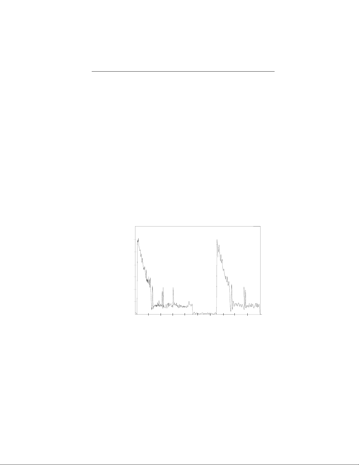
1.6 Start and stop time
Within 10 seconds, the drive is ready. Typical and maximum start and
stop times are shown in the following table. Figure 1 shows a typical
startup current profile.
Typical Maximum
Start time 7 sec 10 sec
Stop time 6 sec 9 sec
Current mA
1,200
1,000
800
600
400
200
2.0 4.0
6.0
8.0
Figure 1. Typi ca l star t up cur re nt prof il e
10.0 12.0
Time (seconds)
14.0
16.0
18.0 20.0
Page 12

4 Medalist 630xe ATA Product Manual, September 1995
1.7 Power specifications
Except during a write operation, you can apply power to the drive or
remove power from the drive in any sequence without losing data or
damaging the drive.
1.7.1 Power-management modes
The drive supports the following power-management modes:
• Active mod e. The drive is seeking, reading or writing.
• Idle mod e. When the drive rec e ives an Idle Imm e diate com mand, or
the idle timer counts down to zero, the drive enters the Idle mode. In
Idle mode, the spindle remains up to speed. The segmented cache
remains enabled, and the drive accepts all com mands and returns to
the Active mode whenever a seek, read or write operation is needed.
• Standby mod e. When the drive receives a Standby Immediate com mand, or the standby timer has counted down to zero, the drive enters
the Standby mode. In the Standby mode, the segmented cache
remains enabled, the heads are parked in the shipping zone and the
spindle is stopped. The dr ive accepts all c ommands and r eturns to the
Active mode whenever a seek, read or write operation is needed.
• Sleep mo de. When the drive receives a Sleep Immediate command,
it enters the Sleep mode. The heads are parked in the shipping zone
and the spindle is at rest. A hard reset or a soft reset returns t he drive
to Active mode. A soft reset preserves the current emulation and
translation parameters.
1.7.1.1 Idle and Standby timers
The drive can enter the Idle mode or the Standby mode by eit her of tw o
methods:
• The computer sends an Idle Immediate command or a Standby
Immediate command.
• The idle timer or the standby timer counts down to zero.
The Idle and Standby timers are disabled at the factory. Use the computer’s setup utility to enable and set the timer delays. When the Idle
timer is enabled, it is initialized each time the drive completes a read,
write or seek.
If the Idle timer reaches zero before any drive activity is required, the
drive goes into the Idle mode, and the Standby timer, if it is enabled, is
initialized. If the Standby timer reaches zero before any drive activity is
Page 13
Medalist 630xe ATA Product Manual, September 1995 5
required, the drive goes into the Standby mode. See the
Interface Reference Manual
, publication number 36111-
Seagate A T A
xxx
for details.
In both the Idle and Standby modes, the driv e accepts all com mands and
returns to the Act ive mode any time disc access is necessary . There may
be a slight delay between the time the drive receives the command an d
drive activity begins.
1.7.1.2 Power consumption
The following guidelines are used to measure power consumption:
• All measurements are taken at sea leve l with an ambient temperature
of 25° C.
• All typical measurements are taken us ing nominal v oltages; the peak
startup power is measured using the nominal voltages.
• Seek current measurements are taken using an RMS meter while th e
drive is randomly seeking with two spindle rotations between each
seek.
Mode
Spinup (peak) 1.2 0. 3 5 8.5
Active
Seeking (typ) 0.34 0.23 5.23
Read/write (typ)
2
(typ)
Idle
Standby
Sleep
2
(typ) 0.025 0.085 0.725
2
(typ) 0.025 0.070 0.650
Current (amps)
Power (watts)
+12V +5V
3
0.145 0.32 3.34
0.12 0.085 1.865
1.7.2 Voltage tolerances
+5V +12V
Voltage tolerance
including noise
2. These values apply only when power management is enabled. To enable power
management, use the computer setup utility.
3. Spinup power is averaged over 7 seconds.
± 5% ± 5%
± 10% during spinup
Page 14

6 Medalist 630xe ATA Product Manual, September 1995
1.7.3 Conducted noise
The drive is expected to operate with a maximum of:
• 150 mV peak-to-peak triangular-wave injected noise at the power
connector. The frequency is 10 Hz to 100 KHz with equivalent resistive
4
loads.
• 100 mV peak-to-peak triangular-wave injected noise at the power
connector. The frequency is 100 KHz to 10 MHz with equivalent
resistive loads.
4
1.7.4 Environment
The acceptable environmental conditions for the drive are specified
below . The specific ations in this section are defined as follows:
• Operating specifications assume that the drive is powered up.
• Nonoperating specifications assume that the drive is packaged as it
was shipped from the factory.
1.7.5 Ambient temperature
Operating 5° to 55° C (41° to 131°F)
Nonoperating –40° to 70° C (–104° to 158°F)
1.7.6 Temperature grad ien t
Operating (max) 20°C per hour (36°F per hour)
Nonoperating (max) 30°C per hour (54°F per hour)
4. Equivalent resistance is calculated by dividing the respective voltage by the typical RMS
read/write current.
Page 15

Medalist 630xe ATA Product Manual, September 1995 7
1.7.7 Relative humidity
Operating 8% to 80% noncondensing
Maximum wet bulb 29.4°C (85.0°F )
Nonoperating 5% to 95% noncondensing
Maximum wet bulb 40.0°C (104.0°F )
1.7.8 Altitud e
Operating –1,000 ft to 10,000 ft (–305 m to 3,050 m)
Nonoperating –1,000 ft to 40,000 ft (–305 m to 12,200 m)
1.7.9 Shock and vibrat ion
Shock measurements are based on an 11 msec, half sine wave shock
pulse, not to be repeated m ore than twice per second. T he specifications
in the table below are defined as follows:
• During normal operating shock and vibration, the drive sustains no
physical damage and reads and writes data without errors.
• During abnormal operating shock and vibration, the drive sustains n o
physical damage, but performance is adversely affected.
• During nonoperating shock and vibration, the read/write heads are in
the shipping zone and the drive sustains no physical damage.
Normal
operating
Shock 2.0 Gs 10.0 Gs 75.0 Gs
5–22 Hz vibration 0.020-inch
displacement
peak-to-peak
22–300 Hz vibration 1.0 G
peak-to-peak
Abnormal
operating Nonoperating
0.030-inch
displacement
peak-to-peak
1.5 Gs
peak-to-peak
0.160-inch
displacement
peak-to-peak
8.0 Gs
peak-to-peak
1.8 Acoustics
Sound pressure is measured at idle from 1 meter above the drive top
cover.
Sound pressure, typ 29 dBA
Sound pressure, max 33 dBA
Page 16

8 Medalist 630xe ATA Product Manual, September 1995
1.9 Reliability
The MTBF and contact start-stop specifications ass ume nominal power
at sea level with an ambient temperature of 25°C.
Nonrecoverable errors 1 per 10
MTBF 300,000 power-on hours
Contact start-stop (CSS) 40,000 cycles
MTTR 30 minutes
Service life 5 years
13
bits read
1.10 Auto-park
Upon power-down, the read/write heads automatically move to the
shipping zone. The heads park inside the maximum data cylinder. When
power is applied, the heads recalibrate to track 0.
1.11 Agency listings
This drive is listed with agencies as follows:
• UL 1950
• CSA C22.2 No. 0-M91 and CSA C22.2 No. 950-M89
• EN 60950/10.92 as tested by TUV-Rheinland, North America
1.12 FCC verification
The ST3630A drive is intended to be contained solely within a personal
computer or similar enclosure (not attached to an external device). As
such, a drive is considered to be a subassembly even when individually
marketed to the customer. As a subassembl y, no Federal Communications Commission authorization, verific ation or certification of the device
is required.
Seagate Technology, Inc. has tested the drive in an enclosure as described above to ensure that the total assembly (enclosure, disc drive,
motherboard, power supply, etc.) does comply with the limits for a
Class B computing device, pursuant to Subpart J of Part 15 of the FCC
rules. Operation with noncertified assemb lies is likely to result in interference to radio and television reception.
Page 17

Medalist 630xe ATA Product Manual, September 1995 9
Radio and television interferen ce. This equipment generates and uses
radio frequency energy and, if not installed and used in strict accor dance
with the manufacturer’s instruc tions, may cause interference to radio an d
television reception.
This equipment is designed to provide reasonable protection against
such interference in a residential installation. However, there is no
guarantee that interference will not occur in a particular installation. If this
equipment does cause interference to radio or television, which can be
determined by turning the equipment on and off, you are encouraged to
try one or more of the following corrective measures:
• Reorient the receiving antenna.
• Move the device to one side or the other of the radio or TV.
• Move the device farther away from the radio or TV.
• Plug the equipment into a different outlet so that the receiver and
computer are on different branch outlets.
If necessary, you should consult your dealer or an experienced radio/television technician for additional suggestions. You may find helpful the
following booklet prepared by the Federal Communications Commission:
How to Identify and Resolve Radio-Television Interference Problems.
This booklet is available from the Superintendent of Documents, US
Government Printing Of fice, Washington, DC 20402. Refer to publication
number 004-000-00345-4.
Page 18

Page 19

Medalist 630xe ATA Product Manual, September 1995 11
2.0 Configuration and mounting
This section discusses the ATA interface connector and other physical
features of the drive, including mounting. Figure 3 on page 13 s hows th e
location of the following features:
• The ATA interface connector
• The power connector
• The master/slave jumper block
• The optional drive activity LED
A brief discussion of each start s on page 12.
2.1 Handling and static-discharge precautions
After you unpack the drive, and before you install it in a computer, be
careful not to damage it through mishandling. Wool and synthetic clothing, carpet, plastics and Styrofoam are contributor s to the static build-up
that can damage sensitive components when discharged through touch.
Observe the following standard handling and static-discharge precautions:
Caution:
• Keep the drive in its static-shielded bag until you are r eady to complete
the installation. Do not attach any cables to the drive while it is in its
static-shielded bag.
• Wear a grounded wrist strap that is properly connected to earth
ground, or ground yourself frequently by touching the metal chassis
of a power supply that is plugged into a grounded outlet when handling
the drive and throughout the entire installation procedure.
• Handle the drive by its edges or frame only.
• The drive is extremely fragile—handle it with care. Do not press down
on the drive top cover.
• Always rest the drive on a padded, antistatic surface until you mount
it in the computer.
• Do not touch the connector pins or the printed circuit board. Do not
touch the printed circuit cable between the circuit board and the
head/disc assembly.
• Do not remove the factory-installed labels from the drive or cover them
with additional labels. If you do, you void the warranty. Some f actoryinstalled labels contain information needed to service the drive. Others
are used to seal out dirt and contamination.
Page 20

12 Medalist 630xe ATA Product Manual, September 1995
2.2 The ATA interface connector
The drive uses a standard 40-pin interface connector with 2 rows of 20
male pins. Pin 20 is removed. The connector is shown in Figure 2.
For the mating connector, use a 40-pin, nonshielded connector with 2
rows of 20 female contacts. We recommend t he following part numbers:
AMP 499496
Berg Electronics 66900-040
Dimensions are in inches
0.230 ± 0.003
0.025 ± 0.002
0.70 ± 0.010
0.100 ± 0.010
0.235 ± 0.025
0.025
± 0.002
0.160
1.90
2.00
Figure 2. The dri ve int erf ac e conn ect or
0.100 typ
0.070 ± 0.010
2.3 Power connector
The drive comes with a standard 4-pin power connector. It is also
available with a standard 3-pin power connector .
2.4 Master/slave jumper block
Figure 3 shows the locat ion of the mast er/slave jumper block and shows
how to install the jumpers for various configurations. The jumper block
accepts 2-mm (0.079-i nch) jumpers. A spare jumper is attached to the
jumper block. If you need additional jumpers, use Seagate part number
10562-001 or an equivalent.
Caution. If you use a jumper that is not the correct size, you may damage
the jumper block and the jumper. Use the jumpers supplied
with the drive.
Page 21

Medalist 630xe ATA Product Manual, September 1995 13
4-pin
power connector
2
4
3
1
Circuit board
+5V
+5V return
+12V return
+12V
Front
2-pin
header
–
+
Pin 1
40-pin
ATA interface
connector
Keyway
Circuit
board
3-pin
power connector
(optional)
3
1
2
Ground
+12V
+5V
master/slave jumper block
8-pin
587
Front
21436
The drive is a master;
the slave is either a
Medalist family drive or
another ATA-compatible
drive, or there is no slave.
The drive is a master;
a slave is present, but
it is not ATA-compatible.
The drive is a master; a
slave is present that uses
only the PDIAG– signal.
The drive is a slave to an
ATA-compatible master.
Cable select
Drive activity
LED
(optional)
Spare jumper
across pin 1 and pin 3
Figure 3. Connector s and jum per s
2.4.1 Single-drive configuration
Use the factory-default jumper setting when the ST3630A drive is installed as the single drive in the computer.
2.4.2 Two-drive configuration
When two drives are installed in the computer, you must configure one
drive as the master and the other as the slave.
Page 22

14 Medalist 630xe ATA Product Manual, September 1995
2.4.2.1 The ST3630A drive as master
The ST3630A provides three ways the slave can identify itself. You can
configure the ST3630A for a slave that is:
• An ATA-compatible drive
• A non-ATA-compatible drive that does not conform to the DASP–
timing parameter of the ATA spec
• A non-ATA-compatible drive that does not conform to the DASP–
timing parameter of the ATA spec but negates PDIAG– when the drive
is ready
2.4.2.2 The ST3630A as slave
The ST3630A drive conforms to the A T A standard for slave identificat ion.
If the master drive is a non-ATA-compatible drive, it may not recognize
the ST3630A drive in the slave position. We recommend that you
configure your ST3630A drive as the master when used with a non-A T Acompatible drive.
2.4.3 Cable-select configuration
If your computer and both of your drives support cable select (CSEL),
you can use the cable select option to determine the master and slave.
To configure your drive to use cable select, you need to install jumpers
and to use a special cable-select cable as follows:
• Install a jumper on pins 3 and 4 of the master/slave jumper bl ock as
shown in Figure 3 on page 13. When a jumper is installed in this
position, the drive ignores the jumper installed on pins 7 and 8.
• You must use an interface cable built for cable-select. To make a drive
the master, attach it to the connector that has the CSEL signal l ine
connected to pin 28. To make a drive the slave, attach it to the
connector that has pin 28 unconnected (CSEL is not carried to pin 28
of that cable connector.) Note that CSEL is grounded at the host.
Page 23

Medalist 630xe ATA Product Manual, September 1995 15
Slave
CSEL not carried
to pin 28 of
this connector
Master
Pin 28 grounded
at computer
Computer
Figure 4. Connect i ng ca bl e- sel ect ed drives
2.4.4 Factory-test configuration
Do not install jumpers on pins 5 and 6 and pins 7 and 8 at the same time.
This configuration is used to test the drive at the factory. When jumpers
are installed in both of these positions, the heads continuously seek back
and forth across the media and the drive ignores a ll control signals sent
by the interface.
2.5 Optional drive activity LED
The drive is available with or without the external activity LED shown in
Figure 3 on page 13. This option is available for users for whom the
activity display through the bus is inaccessible or inconvenient. There
are two LED options:
• The LED is mounted directly on the printed circuit board, or
• A two-pin header is mounted on the printed circuit board for a remote
LED. The anode pin of the header is nearest the edge of the PCB.
Page 24

16 Medalist 630xe ATA Product Manual, September 1995
2.6 Mounting the drive
Y ou can mount the drive in any orientat ion using either the bot tom or th e
side mounting holes, as described below. Figure 5 shows the SAE
dimensions for the drive. Figure 6 on page 18 shows the metric dimensions for the drive.
Note. The location of the mounting holes are different for the SAE an d
metric drives. Overall, the drive dimensions are the same.
• SAE drives have an “S” stamped on the frame runner and accept 6-32
UNC screws.
• Metric drives have an “M” stamped on the frame runner and accept
M3 screws.
Bottom mounting holes. Insert four mounting screws not more than
0.20 inches (6 full turns) into the drive frame.
Side mounting holes. Insert four mounting screws not more than
0.13 inches (4 full turns) into the drive frame.
Caution. To prevent damage to the drive:
• Use only mounting screws of the correct size and length.
• Lightly tighten the mounting screws—do not apply more than
6 inch-pounds of torque.
Page 25

Medalist 630xe ATA Product Manual, September 1995 17
Figure 5 shows the dimensions in inches. The mounting holes are located
in different positions for the SAE drive than the mounting holes on the
metric drive shown in Figure 6 on page 18.
0.15 ± 0.01
Six #6-32 UNC-2B mounting holes
2.362 ± 0.010
4.000 ± 0.010
0.630 ± 0.025
0.030
5.77 max
1.000 max
0.250 ± 0.010
1.75 ± 0.0102.375 ± 0.025
Four #6-32 UNC-2B mounting holes
Figure 5. Standar d mount i ng di m ens ion s
4.02 max
3.750± 0.030
Page 26

18 Medalist 630xe ATA Product Manual, September 1995
Figure 6 shows the dimensions in millimeters. This figure s hows that th e
mounting holes for the metric drive are in different positions than the
mounting holes for the SAE drive shown in Figure 5 on page 17.
3.81 ± 0.254
0.762
± 0.635
Six M3 × 0.5 mounting holes
59.995 ± 0.254
89.992 ± 0.254
21.006 ± 0.635
146.56 max
70.002 ± 0.25430.988
25.4 max
4.978 ± 0.254
Four M3 × 0.5 mounting holes
Figure 6. Metric mounting dimensions
102.108 max
93.98 ± 0.762
Page 27

Medalist 630xe ATA Product Manual, September 1995 19
3.0 ATA interface
The drive uses an A T A interface. The interface is in compliance with ANSI
ATA (AT Attachment) Interface X3.221, Rev. 4; SFF 8011: ATA Timing
Extension for Local Bus Attachments, Rev . 2.0
Data for Drives Under 8 GB
and
Draft Proposal American National
Standards AT Attachment Interface X3.310-948D, Rev. 2E
commands the drive supports are listed in the table on page 22. Commands and features with specific application for the drive are discus sed
in this section. For a general discussion of the Seagate ATA interface,
refer to the
ber 36111-
The ATA interface consists of single-ended, TTL-compatible receivers
and drivers that use an asynchronous interf ace protocol. The drivers can
sink up to 24 mA and drive a load up to 300 pF. The integrity of the ATA
interface is affected by the interface cable. It is designed to support a
40-conductor, nonshielded interface cable with a maximum length of 1 8
inches (0.46 meters).
Seagate A TA Interface Reference Manual
xxx
.
3.1 ATA interface connector pin assignments
The signal name and direction for each I/O connector pin is shown in
Figure 7 on page 20. For a description of each pin, see the
Interface Reference Manual
, publication number 36111-
;
SFF 8019: I dentify Drive
. The ATA
, publication num-
Seagate A TA
xxx.
Signal names are shown in upper-case letters. Signal name followed by
a minus sign (–) indicate the signal is active low . Ot herwise, the signal is
active high.
Note. The drive does not use the SPSYNC– signal.
3.2 Bus signal levels
Signals that the drive sends have the following output characteristics
measured at the drive connector.
Logic low 0 to 0.4V
Logic high 2.5 to 5.25V
Signals that the drive receives must have the following input characteristics measured at the drive connector .
Logic low 0 to 0.8V
Logic high 2.0 to 5.25V
Page 28

20 Medalist 630xe ATA Product Manual, September 1995
Drive pin #
1
2
3
4
5
6
7
8
9
10
11
12
13
14
15
16
17
18
19
20
21
22
23
24
25
26
27
*28
29
30
31
32
33
*34
35
36
37
38
*39
40
*Indicates master-slave signals (details shown below).
Signal name
Reset–
Ground
DD7
DD8
DD6
DD9
DD5
DD10
DD4
DD11
DD3
DD12
DD2
DD13
DD1
DD14
DD0
DD15
Ground
(removed)
DMARQ
SPSYNC−:CSEL
DMACK–
IOCS16–
PDIAG–
CS1FX–
CS3FX–
Ground
DIOW–
Ground
DIOR–
Ground
IORDY
Ground
INTRQ
DA1
DA0
DA2
DASP–
Ground
Host pin # and signal description
1
2
3
4
5
6
7
8
9
10
11
12
13
14
15
16
17
18
19
20
21
22
23
24
25
26
27
28
29
30
31
32
33
34
35
36
37
38
39
40
Host Reset
Ground
Host Data Bus Bit 7
Host Data Bus Bit 8
Host Data Bus Bit 6
Host Data Bus Bit 9
Host Data Bus Bit 5
Host Data Bus Bit 10
Host Data Bus Bit 4
Host Data Bus Bit 11
Host Data Bus Bit 3
Host Data Bus Bit 12
Host Data Bus Bit 2
Host Data Bus Bit 13
Host Data Bus Bit 1
Host Data Bus Bit 14
Host Data Bus Bit 0
Host Data Bus Bit 15
Ground
(No Pin)
DMA Request
Ground
Host I/O Write
Ground
Host I/O Read
Ground
I/O Channel Ready
Cable Select
DMA Acknowledge
Ground
Host Interrupt Request
Host 16 Bit I/O
Host Address Bus Bit 1
Passed Diagnostics
Host Address Bus Bit 0
Host Address Bus Bit 2
Host Chip Select 0
Host Chip Select 1
Drive Active or
Slave Present
Ground
Drive 1
(slave)
28
34
39
Drive 0
(master)
28
34
39
Figure 7. ATA connect or pin assi gn me nt s
SPSYNC−:CSEL
PDIAG
DASP–
–
Host
28
34
39
Page 29

Medalist 630xe ATA Product Manual, September 1995 21
3.3 Supported ATA commands
The table on page 22 lists all AT A commands the drive uses. Commands
that have a particular application for the drive or that may be of special
interest are discussed in this manual. For a complete description of all
ATA interface commands the drive uses, refer to the
Interface Reference Manual
tion is provided by the Small Form Factor specification, SFF-8011 Rev
1.1, September 18, 1993.
The following table lists all commands implemented in the drive. The
table uses the following abbreviations:
FR Features register
SC Sec tor count register
SN Sec tor number register
CY Cylinder register
DH Drive/head register
This register does not contain a valid parameter for this
n
command.
This register conta ins a valid parameter for this command. In
y
the drive/head register, both the drive and head parameters are
valid for this command.
The drive/head register contains a valid drive parameter for this
D
command. The head parameter is not valid for this command.
, part number 361 1 1-
xxx
Seagate ATA
. Additional informa-
Page 30

22 Medalist 630xe ATA Product Manual, September 1995
Command name
Active and Set Idle Timer FB n y n n D
Active Immediate F9 nnnnD
Check Idle Mode FD n y n n D
Check Power Mode 98, E5 n y n n D
Execute Drive Diagnostics 90 nnnnD
Format Track 50 n y n y y
Identify Drive EC nnnnD
Idle 97, E3 n y n n D
Idle and Set Idle Timer FA n y n n D
Idle Immediate 95, F8, E1 nnnnD
Initialize Drive Parameters 91 n y n n y
Read DMA C8, C9 — yyyy
Read Long 22, 23 n yyyy
Read Multiple C4 n yyyy
Read Sector 20, 21 n yyyy
Read Sector Buffer E4 nnnnD
Read Verify Sector 40, 41 n yyyy
Recalibrate 1X nnnnD
Seek 7X n n y y y
Set Features EF y n n n D
Set Multiple Mode C6 n y n n D
Set Sleep Mode 99, E6 nnnnD
Standby 96, E2 nnnnD
Standby Immediate 94, E0 nnnnD
Write DMA CA, CB —yyyy
Write Long 32, 33 n yyyy
Write Multiple C5 n yyyy
Write Sector 30, 31 n yyyy
Write Sector Buffer E8 nnnnD
Command
code (in hex)
Parameters used
FR SC SN CY DH
Page 31

Medalist 630xe ATA Product Manual, September 1995 23
3.3.1 Identify Drive command (ECH)
The Identify Drive command transf ers inf ormat ion about t he drive to th e
host after power up. T he dat a is or ganized as a single 512-byte block of
data. The block’s content s are shown in the table below. All reserved bit s
or words must be set to zero. Parameters listed with an “x” are drive-sp ecific or vary with the state of the drive.
The parameters for the drive are listed in the ta ble below . For a complete
description of the Identify Drive command, see the
Reference Manual
, publication number 36111-
Word Description Value
0 Configuration 045A
Bit 10: 1 = disc transfer rate
> 10 Mbits/sec
Bit 6: 1 = fixed drive
Bit 4: 1 = head switch time
> 15 µsec
Bit 3: 1 = not MFM encoded
Bit 1: 1 = hard-sectored disc
1
2
3
4
5
6
7–9
10–19
20
21
22
Default cylinders 1,223
Reserved 0000
Default heads (default) 16
Bytes per track 8D90
Bytes per sector 0248
Default sectors per track 63
Vendor-unique 0000
Serial number Drive-unique: 20 ASCII
characters
Buffer type 0003
caching
Buffer size (number of
00F0
512-byte sectors)
ECC bytes (R/W Long) 0010
23–26 Firmware revision Drive-dependent: 8 ASCII
characters
27–46 Model number ST3630A
Seagate A TA Interface
xxx
.
H
H
H
H
H
Multisector with
H
(240D)
H
(16D)
H
continued
Page 32

24 Medalist 630xe ATA Product Manual, September 1995
continued fro m previous pa g e
Word Description Value
47 Maximum sectors per
0010
H
interrupt on read/write
multiple
48 Double word I/O 0000H Not supported
49 Capabilities 0B00
DMA, IORDY and LBA
H
supported
50 Reserved 0000
51
52
PIO timing mode 0200
DMA timing mode 0200
Current valid 0003
H
H
Single-word DMA
H
supported
Bit 0 = 1 indicates the
H
fields reported in
53
words 54–58 are valid;
Bit 1 = 1 indicates the
fields reported in words
64–8 are valid
54 Current cylinders 1,223
55 Current heads 16
56 Current sectors per
63
track
57–58 Current sectors 1,232,784
59
Current multiple sector
setting
01
xx
H
60–61 LBA total sectors 1,232,784
62
63
64
65
66
Single-word DMA 07
H
Modes 0, 1 and 2 are
supported
Multiword DMA 0103
Modes 0 and 1 are
supported
Advanced PIO 0001
Minimum multiword
150 nsec
DMA transfer per word
Recommended
150 nsec
multiword DMA transfer
per word
No modes are active;
Mode 0 is active;
H
Mode 3 is supported
H
Page 33

Medalist 630xe ATA Product Manual, September 1995 25
Word Description Value
67
68
69–127
128–159
160–255
Minimum PIO without
IORDY
Minimum PIO with
IORDY
5
Reserved 0000
Reserved
Reserved 0000
400 nsec
180 nsec
H
xxxx
H
H
3.3.2 Format track command (50H)
The drive accepts a Format track command (50H) and the 512 bytes of
the format data transf erred by the host. However, the command does not
mark bad sectors, reassign sector s or unreassign sectors. The first sector
data the host transfers is ignored. A 00 data patt ern is written to the track
specified in the command.
5. Cycle times less than 400 nsec require IORDY.
Page 34

26 Medalist 630xe ATA Product Manual, September 1995
3.3.3 Set Features command (EFH)
The host uses the Set Features command (command code EFH) to
establish parameters that affect the execution of certain dri ve features.
To use the command:
1. Write the Feature value to the Features re gister.
2. Write the Set Features command to the com mand register .
Note. If the value in the Feat ures register is not supported or is invalid,
the drive posts an Aborted Command error.
At power-on, or after a hard reset, the feature select ions are res tored t o
the factory-default values. If 66
change the feature selections (thi s can be canceled by setting CC
66
has not been set, a soft reset returns the settings to the factory
H
defaults.
The following table shows the alterable features the drive supports.
Where a factory default value exists, that value is listed.
Byte Feature description
has been set, a softwar e reset does not
H
H
). If
02
03
44
55
66
82
AA
BB
CC
Enable write cache (factory default).
H
Set value for Set Transfer mode based on value in Sector
H
Count register.
Use maximum length of ECC (16 bytes) on read long/write
H
long commands (factory default).
Disable read look-ahead feature.
H
Use current settings as default (until hard reset or power off).
H
Disable write cache.
H
Enable read look-ahead feature (factory default).
H
4 bytes of ECC apply on read long/write long commands.
H
Enable reverting to power-on defaults (factory default).
H
Page 35

Medalist 630xe ATA Product Manual, September 1995 27
3.3.3.1 PIO and DMA Data Transfer Modes
You can set the multiword DMA m ode and ident ify the P IO data-t ransf er
mechanism and transfer mode with the Set Features command. To set
the multiword DMA mode:
1.1. Write Set Features command value 03
(Set Data Transfer mode) t o
H
the Features register.
2. Write a transfer types value to the Sector Count reg ister. The upper 5
bits of this value define the type of data transfer, and the lower 3 bits
encode the mode value.
This changes word 63 of the Identify Drive command to the mode you
enter in the Sector Count register.
The following table identifies allowable transfer types values:
Data-Transf er Mechan i sm Transfer Types value
Mechanism na me
PIO Transfer Mode (default:
Set PIO Mode = 2)
PIO Transfer Mode:
Set PIO Mode = 2
PIO Flow Control Transfer
Mode: Set PIO Mode = 0
PIO Flow Control Transfer
Mode: Set PIO Mode = 1
PIO Flow Control Transfer
Mode: Set PIO Mode = 2
PIO Flow Control Transfer
Mode: Set PIO Mode = 3
Multiword DMA Mode
Multiword DMA Mode
Reserved
Mode
value
2 00000 000
2 00000 001
0 00001 000
1 00001 001
2 00001 010
3 00001 011
0 00100 000
1 00100 001
— 01000
Data
Upper 5 bits
Lower 3 bits
nnn
If the drive does not support a commanded mode, the drive returns an
Aborted Command error.
If the drive receives a Set Features command with a Mechani sm and
mode value of 00000 001 and the drive supports disabling of IORDY,
then the drive sets its default PIO transfer mode and disables IORDY.
Page 36

28 Medalist 630xe ATA Product Manual, September 1995
3.3.4 S et Mul tiple Mode command (C6H)
Command code C6H enables the drive to perform Read and Write
Multiple operations and establishes the block count for thes e commands.
You do not have to issue this command before every Read Multiple or
Write Multiple command.
The Sector Count register is loaded with the number of sectors per block.
Drives normally support block sizes of 2, 4, 8 and 16 sectors. However ,
other block-size values may also be supported, depending on the size
of the drive’s buffer. After receiving the Set M ultiple Mode com mand, the
drive sets BSY=1 and checks the Sector Count register.
If the Sector Count register contains a valid value and the block count is
supported, the value is loaded for all subsequent Read Multiple and W rite
Multiple commands and execution of those commands is enabled. If a
block count is not supported, an Aborted Comm and er ror is posted, a nd
Read Multiple and Write Multiple commands are disabled.
If the Sector Count register contains 0 when the command is issued,
Read and Write Multiple commands are disab led.
At power on, or after a hardware reset, the default mode is Read and
Write Multiple disabl ed. If Disable Default has been set in the Features
register , then the mode remains the same as that last established before
a software reset. Otherwise it reverts to the default of disabled.
3.3.5 Read Multiple command (C4H)
This command (code C4H) is similar to the Read Sectors command.
Interrupts are not generated on every sector, but on the transfer of a block
that contains the number of sectors defined by a Set Multiple Mode
command.
The number of sectors per block to be transferred without intervening
interrupts is programmed by the Set Multiple Mode command, which
must be executed before the Read Multiple command. Interrupts are
generated when DRQ is set to 1 at the beginning of each block or partial
block.
When the Read Multi ple command is issued, the Sector Count register
contains the number of sectors (not the number of blocks or the bl ock
count) requested.
Page 37

Medalist 630xe ATA Product Manual, September 1995 29
If the number of requested sectors is not evenly divisibl e by the block
count, as many full blocks as possible are transferred, followed by a final,
partial block transfer. The partial block transfer is for
n
= remainder (sector count / block count)
If the Read Multiple command is attempted before the S et Multiple Mode
command has been executed or when Read Multiple commands are
disabled, the Read Multiple operation is rejected with an Aborted Command error .
Disc errors encountered during Read Multiple commands are posted at
the beginning of the block or partial block transfer, but DRQ is still set
and the data transfer takes place as it normally would, including transfer
of corrupted data, if any.
The contents of the Command Block registers, following the transfer of
a data block that had a sector in error, are undefined. The host should
retry the transfer as individual requests to obtain valid error infor mat ion.
Subsequent blocks or partial blocks are transferred only if the error was
a correctable data error . All other errors cause the command to s top after
the block containing the error is transferred.
n
sectors, where
3.3.6 Write Multiple command (C5H)
This command (command code C5H) is similar to the Write Sectors
command. Interrupts are not presented on each sector but on the transfer
of a block that contains the number of sectors defined by Set Multiple
Mode command.
The number of sectors per block to be transferred without intervening
interrupts is programmed by the Set Multiple Mode command, which
must be executed before the Write Mu ltip le command.
When the Write Multiple command is issued, the Sector Count register
contains the number of sectors (not the number of blocks or the bl ock
count) requested.
If the number of requested sectors is not evenly divisibl e by the block
count, as many full blocks as possible are transferred, followed by a final,
partial-block transfer . The parti al-b lock transfer is for
n = remainder (sector count / block count)
If the Write Multiple command is attempt ed before the Set Multiple Mo de
command has been executed or when Write Multiple commands are
disabled, the Write Multiple operation is rejected with an aborted command error .
n
sectors, where
Page 38

30 Medalist 630xe ATA Product Manual, September 1995
Disc errors encountered during Write Multiple commands are posted
after the attempted disc write of the block or partial block transferr ed. The
Write command ends with the sector in error , even if it was in the middle
of a block. Subsequent blocks are not transferred in the event of an error.
Interrupts are generated when DRQ is set to 1 at the beginning of each
block or partial block.
The contents of the Command Block registers are undefined when t hey
follow the transfer of a data block that had a sector in error. The host
should retry the transfer as individual requests to obtain valid error
information.
3.4 Onboard drive diagnostic s
During startup, the drive executes a series of diagnostic tests. If the
diagnostic tests detect an error, the drive LED indicates the nature of the
error by emitting a flash code. A subset of the error flash codes is
contained in the following table:
Number of
flashes
Irregular flashes Microprocessor error
2 ROM checksum error
3 External RAM error
4 I/O chip error
5 Buffer RAM error
Error code description
3.5 ECC performance tests
The drive does not report ECC errors when it performs on-the-fly error
correction. This allows the drive to correct the data without sacrificing
performance.
Some older drive diagnostic utilities test the drive’s ability to apply ECC
by creating small data errors and then checking to see if these errors are
reported. If you run one of these tests on a drive that is functioning
properly , the test may report that the drive is failing to detect ECC errors.
However, this does not mean that the drive is malfunctioning.
Page 39

Medalist 630xe ATA Product Manual, September 1995 31
3.6 Supported BIOS
The drive uses 16 bytes of ECC with Read Long and Write Long
commands. If the computer BIOS expect s less than 16 bytes, some drive
diagnostics may return f alse failures (ty pically time- out errors). If so, you
must reconfigure the computer to receive 4 bytes of ECC.
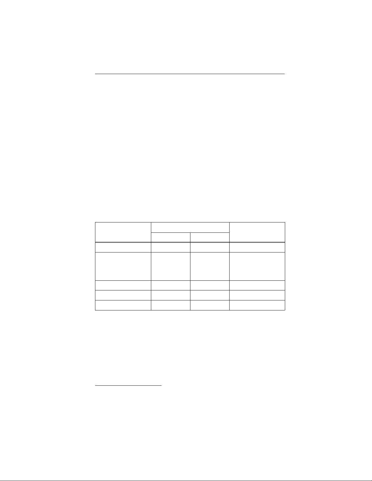
The BIOS revisions listed in the following table are fully compatible with
the A T A interface the driv e uses. Earlier BIO S revisions than those listed
may not fully support the A TA interface as implem ented on the drive.
BIOS manufactur er Version supported
American Megatrends Dated 4/9/90 or later
Award 3.04 or higher
Quadtel Single drive, any version
Dual drive, 3.04 or higher
Phoenix ROM BIOS Plus 286, 3.10 or higher
ROM BIOS Plus 386, 1.10 or higher
PhoenixBIOS 1.00 or higher
Page 40

Page 41

Page 42

Page 43

Page 44

Seagate Technology, Inc.
920 Disc Drive, Scotts Valley, Cali forni a 95066, USA
Publication Numb er: 3633 0-1 01 , Septem be r 1995, Printe d in USA
 Loading...