

Seagate MEDIALIST 1080SL Product manual

. . . . . . . . . . . . . . . . . . . . . . . . . . . . . . . . . . . . .. . . . .
Medalist 1080sl
. . . . . . . . . . . . . . . . . . . . . . . . . . . . . . . . . . . . .. . . . .
SCSI Interface Drive
. . . . . . . . . . . . . . . . . . . . . . . . . . . . . . . . . . . . .. . . . .
. . . . . . . . . . . . . . . . . . . . . . . . . . . . . . . . . . . . .. . . . .
. . . . . . . . . . . . . . . . . . . . . . . . . . . . . . . . . . . . .. . . . .
Product Manual
. . . . . . . . . . . . . . . . . . . . . . . . . . . . . . . . . . . . .. . . . .


. . . . . . . . . . . . . . . . . . . . . . . . . . . . . . . . . . . . .. . . . .
Medalist 1080sl
. . . . . . . . . . . . . . . . . . . . . . . . . . . . . . . . . . . . .. . . . .
SCSI Interface Drive
. . . . . . . . . . . . . . . . . . . . . . . . . . . . . . . . . . . . .. . . . .
. . . . . . . . . . . . . . . . . . . . . . . . . . . . . . . . . . . . .. . . . .
. . . . . . . . . . . . . . . . . . . . . . . . . . . . . . . . . . . . .. . . . .
Product Manual
. . . . . . . . . . . . . . . . . . . . . . . . . . . . . . . . . . . . .. . . . .

© 1995 Seagate Technology, Inc. All rights reserved
Publication Number: 36321-101, Rev. A, August 1995
Seagate, Seagate Technology and the Seagate logo are registered
trademarks of Seagate Technology, Inc. Medalist
SL is a trademark of
Seagate Technology, Inc. Other product names are trademarks or
registered trademarks of their owners.
Seagate reserves the right to change, without notice, product offerings
or specifications. No part of this publication may be reproduced in any
form without written permission from Seagate Technology, Inc.

Medalist 1080sl SCSI Product Manual, August 1995 iii
Contents
Introduction . . . . . . . . . . . . . . . . . . . . . . . . . . . . . 1
Quick specification chart . . . . . . . . . . . . . . . . . . . . . . 2
1.0 Specifications summary . . . . . . . . . . . . . . . . . . . . . 4
1.1 Formatted capacity . . . . . . . . . . . . . . . . . . . . . . . 4
1.2 Physical geometry . . . . . . . . . . . . . . . . . . . . . . . 4
1.3 Functional specifications . . . . . . . . . . . . . . . . . . . . 4
1.4 Physical dimensions . . . . . . . . . . . . . . . . . . . . . . 5
1.5 Seek time . . . . . . . . . . . . . . . . . . . . . . . . . . . . 5
1.5.1 Read look-ahead and caching . . . . . . . . . . . . . . 5
1.6 Start and stop time . . . . . . . . . . . . . . . . . . . . . . . 6
1.6.1 Power-up sequence . . . . . . . . . . . . . . . . . . . . 6
1.6.2 Power-down sequence . . . . . . . . . . . . . . . . . . 7
1.6.3 Auto-park . . . . . . . . . . . . . . . . . . . . . . . . . 7
1.7 Power management . . . . . . . . . . . . . . . . . . . . . . 7
1.7.1 Power consumption . . . . . . . . . . . . . . . . . . . . 8
1.7.2 Voltage tolerance . . . . . . . . . . . . . . . . . . . . . 8
1.7.3 Input noise . . . . . . . . . . . . . . . . . . . . . . . . . 9
1.8 Environmental . . . . . . . . . . . . . . . . . . . . . . . . . 9
1.8.1 Ambient temperature . . . . . . . . . . . . . . . . . . . 9
1.8.2 Temperature gradient . . . . . . . . . . . . . . . . . . . 9
1.8.3 Altitude . . . . . . . . . . . . . . . . . . . . . . . . . . 9
1.8.4 Relative humidity . . . . . . . . . . . . . . . . . . . . 10
1.9 Shock and vibration . . . . . . . . . . . . . . . . . . . . . 10
1.10 Acoustics . . . . . . . . . . . . . . . . . . . . . . . . . . 10
1.11 Reliability . . . . . . . . . . . . . . . . . . . . . . . . . . 11
1.12 Agency listings . . . . . . . . . . . . . . . . . . . . . . . 11
1.13 FCC verification . . . . . . . . . . . . . . . . . . . . . . . 11

iv Medalist 1080sl SCSI Product Manual, August 1995
2.0 Hardware and interface . . . . . . . . . . . . . . . . . . . . 15
2.1 SCSI-2 compatibility . . . . . . . . . . . . . . . . . . . . . 15
2.2 Handling and static-discharge precautions . . . . . . . . . 15
2.3 Electrical interface . . . . . . . . . . . . . . . . . . . . . . 16
2.4 SCSI interface connector . . . . . . . . . . . . . . . . . . 17
2.4.1 SCSI interface connector pin assignments . . . . . . . 18
2.5 Interface cable requirements . . . . . . . . . . . . . . . . . 19
2.5.1 Interface cable length for asynchronous operation . . . 21
2.5.2 Interface cable for Fast SCSI operation . . . . . . . . . 21
2.6 Options jumper block . . . . . . . . . . . . . . . . . . . . . 21
2.6.1 SCSI address . . . . . . . . . . . . . . . . . . . . . . 22
2.6.2 Active Termination . . . . . . . . . . . . . . . . . . . 22
2.6.3 Terminator power source selection . . . . . . . . . . . 22
2.6.4 Parity enable option . . . . . . . . . . . . . . . . . . . 23
2.6.5 Start/stop option . . . . . . . . . . . . . . . . . . . . . 23
2.6.6 Remote LED connection . . . . . . . . . . . . . . . . 23
2.7 Daisy chaining . . . . . . . . . . . . . . . . . . . . . . . . 23
2.8 Hot-plugging . . . . . . . . . . . . . . . . . . . . . . . . . 23
2.9 Mounting the drive . . . . . . . . . . . . . . . . . . . . . . 24
3.0 Command set . . . . . . . . . . . . . . . . . . . . . . . . . 27
3.1 Command descriptor block . . . . . . . . . . . . . . . . . . 27
3.2 Status byte . . . . . . . . . . . . . . . . . . . . . . . . . . 27
3.3 Supported commands . . . . . . . . . . . . . . . . . . . . 29
3.4 Group 0 commands . . . . . . . . . . . . . . . . . . . . . 30
3.4.1 Test Unit Ready command (00
3.4.2 Rezero Unit command (01
3.4.3 Request Sense command (03
3.4.4 Format Unit command (04
3.4.5 Reassign Blocks command (07
3.4.6 Read command (08
3.4.7 Write command (0A
) . . . . . . . . . . . . . . . . . . 39
H
) . . . . . . . . . . . . . . . . . . 40
H
) . . . . . . . . . . . . 30
H
) . . . . . . . . . . . . . . 30
H
) . . . . . . . . . . . . 30
H
) . . . . . . . . . . . . . . 32
H
) . . . . . . . . . . . . 37
H

Medalist 1080sl SCSI Product Manual, August 1995 v
3.4.8 Seek command (0BH) . . . . . . . . . . . . . . . . . . 41
3.4.9 Inquiry command (12
3.4.10 Mode Select command (15
3.4.11 Reserve command (16
3.4.12 Release command (17
3.4.13 Mode Sense command (1A
3.4.14 Start/Stop Unit command (1B
3.4.15 Receive Diagnostic Results command (1C
3.4.16 Send Diagnostic command (1D
) . . . . . . . . . . . . . . . . . 41
H
) . . . . . . . . . . . . . 42
H
) . . . . . . . . . . . . . . . 45
H
) . . . . . . . . . . . . . . . . 46
H
) . . . . . . . . . . . . . 47
H
) . . . . . . . . . . . . 50
H
) . . . . . 51
H
) . . . . . . . . . . . 52
H
3.5 Group 1 commands . . . . . . . . . . . . . . . . . . . . . 53
3.5.1 Read Capacity command (25
3.5.2 Read Extended command (28
3.5.3 Write Extended command (2A
3.5.4 Seek Extended command (2B
3.5.5 Write and Verify command (2E
3.5.6 Verify command (2F
) . . . . . . . . . . . . . . . . . 58
H
3.5.7 Read Defect Data command (37
3.5.8 Write Data Buffer command (3B
3.5.9 Read Data Buffer command (3C
3.5.10 Read Long command (3E
3.5.11 Write Long command (3F
) . . . . . . . . . . . . . 53
H
) . . . . . . . . . . . . 54
H
) . . . . . . . . . . . . 55
H
) . . . . . . . . . . . . 57
H
) . . . . . . . . . . . . 57
H
) . . . . . . . . . . . 58
H
H) . . . . . . . . . . . 60
) . . . . . . . . . . . 62
H
) . . . . . . . . . . . . . . 63
H
) . . . . . . . . . . . . . . 63
H
3.6 Group 2, 3 and 4 commands . . . . . . . . . . . . . . . . . 64
3.7 Group 5 and 6 commands . . . . . . . . . . . . . . . . . . 64
3.8 Group 7 commands . . . . . . . . . . . . . . . . . . . . . 65
Appendix A. Supported messages . . . . . . . . . . . . . . . . 67
A.1 Single-byte messages . . . . . . . . . . . . . . . . . . . . 67
A.2 Synchronous data transfer request message (01
) . . . . . 67
H
Appendix B. Sense data . . . . . . . . . . . . . . . . . . . . . . 69
B.1 Additional sense data . . . . . . . . . . . . . . . . . . . . 69
B.2 Sense key . . . . . . . . . . . . . . . . . . . . . . . . . . 70
B.3 Additional sense code and additional sense code qualifier . 72

vi Medalist 1080sl SCSI Product Manual, August 1995
Appendix C. Mode pages . . . . . . . . . . . . . . . . . . . . . 77
C.1 Error Recovery page (01
C.2 Disconnect/Reconnect page (02
C.3 Format Device page (03
C.4 Rigid Disc Geometry page (04
C.5 Verify error recovery page (07
C.6 Caching page (08
) . . . . . . . . . . . . . . . . . . . . . 89
H
) . . . . . . . . . . . . . . . . . 79
H
) . . . . . . . . . . . . . 81
H
) . . . . . . . . . . . . . . . . . . 82
H
) . . . . . . . . . . . . . . 85
H
) . . . . . . . . . . . . . . . 87
H
C.6.1 Read look-ahead and caching . . . . . . . . . . . . . 89
C.6.2 Write caching and write merging . . . . . . . . . . . . 89
C.6.3 Caching page description . . . . . . . . . . . . . . . . 90
C.7 Control Mode page (0A
C.8 Notch page (0C
) . . . . . . . . . . . . . . . . . . . . . . 95
H
C.9 Cache Control page (38
C.10 Soft ID page (Flash memory) (3C
C.11 Operating page (Flash memory) (00
) . . . . . . . . . . . . . . . . . . 93
H
) . . . . . . . . . . . . . . . . . . 97
H
) . . . . . . . . . . . . 98
H
) . . . . . . . . . . . 99
H
Appendix D. Inquiry data . . . . . . . . . . . . . . . . . . . . 101
D.1 Inquiry data . . . . . . . . . . . . . . . . . . . . . . . . 101
D.2 Vital product data pages . . . . . . . . . . . . . . . . . . 104
D.2.1 Unit Serial Number page (80
D.2.2 Implemented Operating Definition page (81
D.2.3 Firmware Numbers page (C0
D.2.4 Date Code page (C1
) . . . . . . . . . . . . . . . . 107
H
D.2.5 Jumper Settings page (C2
) . . . . . . . . . . . . 105
H
) . . . . 105
H
) . . . . . . . . . . . . 106
H
) . . . . . . . . . . . . . 107
H
Appendix E. Timing diagrams . . . . . . . . . . . . . . . . . . 109

Medalist 1080sl SCSI Product Manual, August 1995 vii
Figures
Figure 1. Typical startup current profile . . . . . . . . . . . . . . . . 6
Figure 2. Single-ended transmitter and receiver . . . . . . . . . . 16
Figure 3. ST51080N connectors . . . . . . . . . . . . . . . . . . 17
Figure 4. Options jumper block settings . . . . . . . . . . . . . . 20
Figure 5. ST51080N mounting dimensions . . . . . . . . . . . . . 25
Figure 6. Arbitration, selection (without ATN) and command . . . 109
Figure 7. Arbitration, selection (with ATN) and message out . . . 110
Figure 8. Identify message out to command . . . . . . . . . . . 111
Figure 9. Command descriptor block transfer . . . . . . . . . . 112
Figure 10. Command, status, command complete message and
bus free . . . . . . . . . . . . . . . . . . . . . . . . 113
Figure 11. Last command byte, disconnect message, bus free
and reselection . . . . . . . . . . . . . . . . . . . . 114
Figure 12. Arbitration, reselection and message in . . . . . . . . 115
Figure 13. Reselection, status, command complete and bus free 116
Figure 14. Last command byte to data in . . . . . . . . . . . . . 117
Figure 15. Last command byte to data out . . . . . . . . . . . . 118
Figure 16. Reselect identify message to data in . . . . . . . . . 119
Figure 17. Data in block transfer . . . . . . . . . . . . . . . . . 120
Figure 18. Data out block transfer . . . . . . . . . . . . . . . . 121
Figure 19. Last data byte, save pointer message and
disconnect message . . . . . . . . . . . . . . . . . 122
Figure 20. Data in, status, command complete message and
bus free . . . . . . . . . . . . . . . . . . . . . . . . 123
Figure 21. Synchronous timing . . . . . . . . . . . . . . . . . . 124
Figure 22. Synchronous write timing . . . . . . . . . . . . . . . 125


Medalist 1080sl SCSI Product Manual, August 1995 1
Introduction
This manual describes the functional, mechanical and interf ace specifications for the Medalist 1080sl SCSI hard disc drive. The Medalist 1080sl
SCSI is referred to throughout this manual by its model number,
ST51080N.
The ST51080N is a high-capacity, high-performance, energy-efficient
SCSI drive that comes in the mini 3.5-inch form-factor.
The drive uses a high-performance SCSI-2 interface that supports an
asynchronous external transfer rate of up to 5 Mbytes per second and a
synchronous external transfer rate of up to 10 Mbytes per second.
The interface is supported with a 128-Kbyte segmented cache and
embedded servo technology. The segmented cache aids the flow of read
and write data. The embedded servo allows for accurate positioning of
the heads over the data and eliminates periodic thermal recalibration to
assure data transfer without interruption.
The ST51080N conforms to the standard 3.5-inch footprint but have a
0.75-inch (19 mm) height profile and a 5.0-inch depth profile. The lower
height and shorter depth gives the designer or integrator more room for
air circulation, other peripherals or a smaller drive bay.
The following is a summary of the drive’s features:
Capacity
• 1.08 Gbytes formatted
Performance
• Uses the SCSI-2 interface
• 5,376-RPM rotational speed
• 128-Kbyte segmented buffer
• 12.5-msec average seek time
Acoustics
• 30-dBA idle acoustic sound level
Mini 3.5-inch form-factor
• 19-mm height profile
• Fits standard 3.5-inch footprint
2 Medalist 1080sl SCSI Product Manual, August 1995
Quick specification chart
The following table serves as a quick reference for the ST51080N
performance specifications. These and other specifications are discussed in the Specification summary section following the table.
Drive specification ST51080N
6
Formatted capacity (Mbytes) (×10
Total sectors 2,109,840
Bytes per sector 512
Sectors per track (average) 115
Physical cylinders 4,826
Physical read/write heads 4
Physical disc 2
Recording density (bits per inch, max) 73,344
Track density (tracks per inch) 4,923
Spindle speed (RPM) 5,376 ± 0.5%
Internal data-transfer rate (Mbits per second max) 33 MHz to 65 MHz
External transfer rate (Mbytes per second max) 5.0 asynchronous
Cache buffer (Kbytes) 128
Height, inches max (mm) 0.748 (19.0)
Width, inches max (mm) 4.01 (102.8)
Depth, inches max (mm) 5.00 (127.0)
Typical weight, lb (g) 0.750 (340.2)
Track-to-track seek time read (msec typical) 3.5
Track-to-track seek time write (msec typical) 4.5
Average seek time read (msec typical) 12.5
Average seek time write (msec typical) 15.5
Full-stroke seek time read (msec typical) 25.0
Full-stroke seek time write (msec typical) 27
Average latency (msec) 5.6
Power-on to ready (sec typical) 20
bytes) 1,080.23
10.0 synchronous
continued

Medalist 1080sl SCSI Product Manual, August 1995 3
continued from previous page
Drive specification ST51080N
Spinup current: +12V (max) 1.32A
Seek power (typical) 7.11W
Read/Write power (typical) 5.14W
Idle power (typical) 4.9W
Voltage tolerance (including noise): +5V ±5%
Voltage tolerance (including noise): +12V ±5%
Ambient temperature, operating (°C) 5° to 55°C
Temperature gradient , operating (°C per hour max) 20°C
Relative humidity, operating gradient (max) 10% per hr
Relative humidity, operating 8% to 80%
Wet bulb temperature, operating (noncondensing) 29.4°C
Altitude, operating –1,000 to 10,000 ft.
Shock, normal operating (Gs max for 11 msec) 2 Gs
Vibration (Gs max at 22–350 Hz without nonrecoverable
errors), operating
Vibration (Gs max at 22–350 Hz with no physical damage
incurred), nonoperating
Drive acoustics, Idle mode (dBA) 30 dBA
Drive acoustics, seeking (dBA) 34 dBA
Nonrecoverable read errors
(per bits transferred)
Mean time between failures (power-on hours) 300,000
Contact start-stop cycles 40,000
Service life (years) 5
0.75 Gs
0 to Peak
4 Gs
0 to Peak
13
10

4 Medalist 1080sl SCSI Product Manual, August 1995
1.0 Specifications summary
1.1 Formatted capacity
The capacities specified here do not include spare sectors and cylinders.
The media contains one spare sector per track and two spare cylinders
per drive.
1
Formatted capacity (Mbytes
Total sectors 2,109,840
1.2 Physical geometry
Discs 2
Read/write heads 4
Cylinders 4,826
1.3 Functional specifications
) 1080.23
Interface Fast SCSI-2
Zone Bit Recording method RLL (1,7)
External data transfer rate
(Mbytes per sec, max)
Internal data transfer rate
(Mbits per sec)
Spindle speed (RPM) 5,376 ± 0.5%
Bytes per sector 512
Track density (TPI) 4,923
Recording density
(BPI, max)
1. One Mbyte equals 1,000,000 bytes.
5.0 asynchronous
10.0 synchronous
33 to 65
73,344

Medalist 1080sl SCSI Product Manual, August 1995 5
1.4 Physical dimensions
Height (max) 0.748 inches (19 mm)
Width (max) 4.00 inches (102.1 mm)
Depth (max) 5.00 inches (127.0 mm)
Weight (max) 0.75 lb (340.2 g)
1.5 Seek time
All seek time measurements are taken under nominal conditions of
temperature and voltage with the drive mounted horizontally. In the
following table:
Track-to-track
•
seek time is the average of all possible single-track
seeks in both directions.
•
Average/typical
seek time is a true statistical random average of at
least 5,000 measurements of seeks in both directions between random cylinders, less overhead.
•
Full-stroke
seek time is one-half the time needed to seek from logical
block address zero (LBA 0) to the maximum LBA and back to LBA 0.
Track-to-track
seek time typ
Average/typical
2
seek time
3
Full-stroke
seek time typ4
Average
latency
4.5 msec read 12.5 msec read 25.0 msec read 5.6 msec
3.5 msec write 15.5 msec write 27.0 msec write
Note. Host overhead varies between systems and cannot be specified.
Drive internal overhead is measured by issuing a no-motion seek.
Drive overhead is typically less than 1.0 msec.
1.5.1 Read look-ahead and caching
The drive uses algorithms that improve seek performance by storing data
in a buffer and processing it at a more convenient time. Three methods
are used: read look-ahead, read caching and write caching. These are
described in Appendix C.6.
2. All possible one track seeks are divided into the time required to perform those seeks.
Only the mechanism time is used; interface overhead is excluded.
3. All possible seeks are divided into the time required to perform those seeks. Only the
mechanism time is used; interface overhead is excluded.
4. The average of 1000 full stroke seeks is used in this computation. Only the mechanism
time is used; interface overhead is excluded.
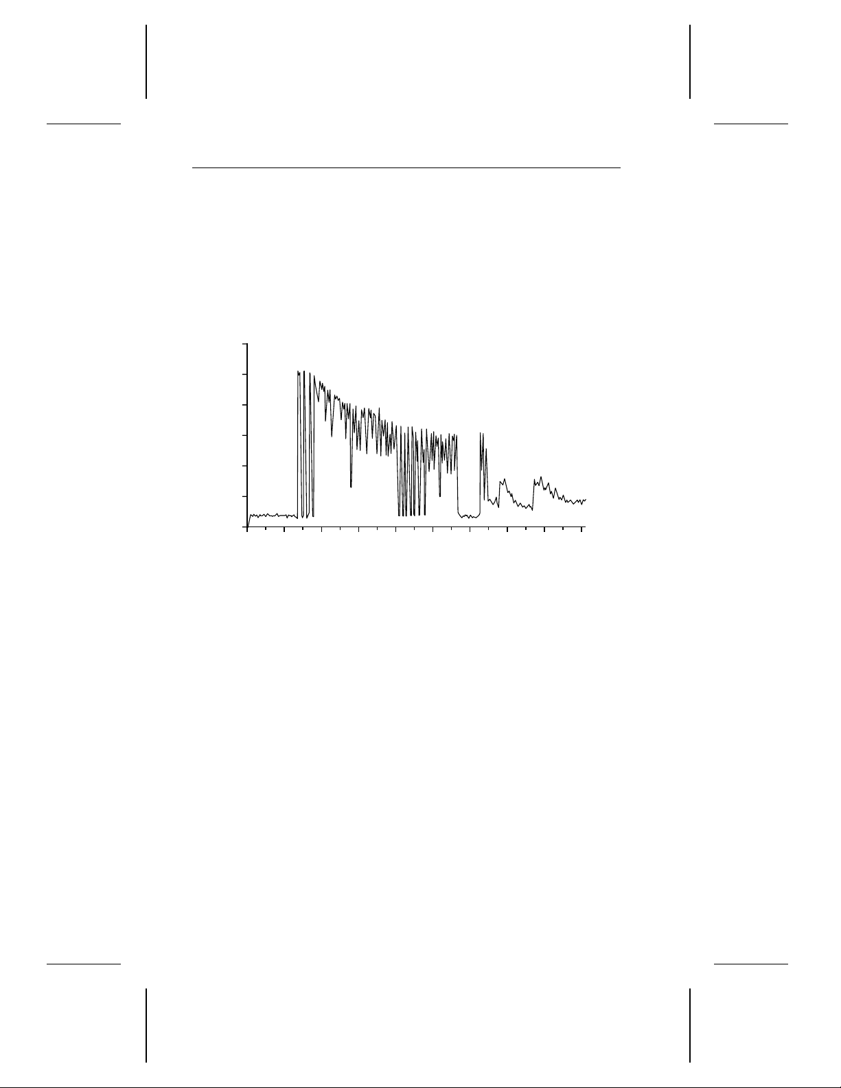
0
0
0.2
0.4
0.6
0.8
1.0
1.2
1
T1
T2
T3
T4 T5
T6
T7
2 3 4 5 6 7 8 9
Amps
Seconds
6 Medalist 1080sl SCSI Product Manual, August 1995
1.6 Start and stop time
If the motor start option is disabled, the drive becomes ready within
20 seconds after power is applied. If the motor start option is enabled,
the drive becomes ready within 20 seconds after it receives the Motor
Start command. If the drive receives a command to spin down or power
is removed, the drive stops within 15 seconds.
Figure 1. Typical startup current profile
1.6.1 Power-up sequence
The following typical power-up sequence is provided to assist in evaluating drive performance. This information does not constitute a specification or a performance guarantee.
1. Power is applied to the disc drive.
2. The LED comes on for about 1 second.
3. Depending on whether there is a jumper installed on pins 15 and 16
of the options jumper block (J8) shown in Figure 3 on page 17, either
of the following sequences occurs:
a. If a jumper is not installed, the remote start option is not enabled,
and the drive begins to spin up as soon as power is applied.
b. If a jumper is installed, the remote start option is enabled, and the
drive begins to spin up when the host commands the motor to start.
4. Within 250 msec after power is applied, the drive responds to the Test
Unit Ready, Request Sense, Mode Sense and Inquiry commands.

Medalist 1080sl SCSI Product Manual, August 1995 7
5. The drive begins to lock in speed-control circuits.
6. The actuator lock releases the actuator.
7. The spindle motor reaches operating speed in about 5 seconds. After
5 seconds, there are no speed variations.
8. The drive performs velocity adjustment seeks.
9. The drive seeks track 0 and becomes ready.
1.6.2 Power-down sequence
The following typical power-down sequence is provided to assist in
evaluating drive performance. This information does not constitute a
specification or a performance guarantee.
1. The power cable is unplugged from the drive, or the drive receives a
command to spin down.
2. Within 3 seconds after the motor begins to spin down, the actuator
lock engages, producing a sound.
3. The spindle stops within 15 seconds, whether the power cable is
unplugged from the drive or the drive receives the power-down
command.
1.6.3 Auto-park
Upon power-down, the read/write heads automatically move to the
landing zone. The heads park beyond the maximum data cylinder. When
power is applied, the heads recalibrate to track 0.
Caution. Do not move the drive until the spindle motor has come to a
complete stop; otherwise, you may damage the drive.
1.7 Power management
The drive supports power-management modes that reduce its overall
power consumption. The drive automatically changes from one mode to
another in response to interface activity. You do not need to change any
parameters or send any special commands to make the drive change
modes. The power-management modes are described below.
• Spinup. Spinup is defined as the period during which the spindle is
coming up to operating speed. The power consumed in this mode is
equivalent to the average power during the first 10 seconds after the
drive begins to spin up.

8 Medalist 1080sl SCSI Product Manual, August 1995
• Seeking. The servo electronics are active, and the heads are moving
to a specific location on the disc. The read/write electronics are
powered-down. The power consumed in this mode is equivalent to the
average power measured while executing random seeks with a 2revolution (26.6 msec) dwell between seeks. The drive enters this
mode from the Idle mode.
• Read/Write. The drive is reading or writing. All electronics are active
and the heads are on track.
• Idle. The motor is up to speed and the drive is in track follow mode.
1.7.1 Power consumption
Values in the table below were measured at the drive power connector
with an RMS DC ammeter. The terminating resistors are disabled, and
terminator power is supplied through the SCSI connector. All values are
measured 10 minutes after the drive spins up except as noted.
During
Spinup Seeking
Current at +12V
Amps peak 1.32 — — —
RMS amps typ — 0.393 0.221 0.219
Watts typ — 4.72 2.65 2.63
Current at +5V
RMS amps typ — 0.477 0.498 0.471
Watts typ — 2.39 2.49 2.36
Power
Total watts typ — 7.11 5.14 4.99
Read/
Write Idle
1.7.2 Voltage tolerance
+5V +12V
Voltage tolerance
(including noise)
± 5% ± 5%

Medalist 1080sl SCSI Product Manual, August 1995 9
1.7.3 Input noise
+5V +12V
Voltage tolerance
(including noise)
Input noise frequency
(max)
Input noise
(max, peak-to-peak)
± 5% ± 5%
25 MHz 25 MHz
100 mV 240 mV
1.8 Environmental
This section specifies acceptable environmental conditions for the drive.
The operating specifications assume that the drive is powered up. The
nonoperating specifications assume that the drive is packaged as it was
shipped from the factory.
1.8.1 Ambient temperature
Operating 5°C to 55°C (41°F to 131°F)
Nonoperating –40°C to 70°C (–40°F to 158°F)
1.8.2 Temperature gradient
Operating 20°C per hour (36°F per hour)
Nonoperating 30°C per hour (54°F per hour)
1.8.3 Altitude
Operating –1,000 ft to 10,000 ft (–305 m to 3,048 m)
Nonoperating –1,000 ft to 40,000 ft (–305 m to 12,192 m)

10 Medalist 1080sl SCSI Product Manual, August 1995
1.8.4 Relative humidity
Operating 8% to 80% noncondensing
Maximum wet bulb 29.4°C (84.9°F)
Operating gradient, max 10% per hour
Nonoperating 5% to 95% noncondensing
Maximum wet bulb 35°C (95.0°F)
1.9 Shock and vibration
All shock and vibration specifications assume that the inputs are measured
at the drive mounting screws. Shock measurements are based on an
11-msec, half sine wave shock pulse, not to be repeated more than twice
per second.
During normal operating shock and vibration, there is no physical damage to the drive or performance degradation.
During abnormal operating shock and vibration, there is no physical
damage to the drive, although performance may be degraded during the
shock or vibration episode. When normal operating shock levels resume,
the drive meets its performance specifications.
During nonoperating shock and vibration, the read/write heads are
positioned in the shipping zone.
Normal
operating
Shock 2 Gs 10 Gs 75 Gs
5–22 Hz vibration 0.020-inch
displacement
22–350 Hz vibration 0.50 Gs 0.75 Gs 4.00 Gs
Abnormal
operating
0.030-inch
displacement
Nonoperating
0.160-inch
displacement
1.10 Acoustics
Sound pressure is measured at idle from 1 meter above the drive top
cover.
Idle Seek
Sound pressure, typ 30 dBA 34 dBA
Sound pressure, max 34 dBA 38 dBA

Medalist 1080sl SCSI Product Manual, August 1995 11
1.11 Reliability
Read error rates are measured with automatic retries and data correction
with ECC enabled and all flaws reallocated. MTBF is measured at
nominal power at sea level and 40°C ambient temperature.
13
Nonrecoverable read errors 1 per 10
Seek errors 1 per 10
MTBF 300,000 power-on hours
Service life 5 years
bits transferred
7
physical seeks
1.12 Agency listings
This drive is listed by agencies as follows:
• Recognized in accordance with UL 478 and UL 1950
• Certified to CSA C22.2 No. 220-M1986 and CSA C22.2 No. 950-
M1989
• Certified to VDE 0806/05.90 and EN 60950/1.88 as tested by VDE
1.13 FCC verification
The ST51080N drive is intended to be contained solely within a personal
computer or similar enclosure (not attached to an external device). As
such, a drive is considered to be a subassembly even when individually
marketed to the customer. As a subassembly, no Federal Communications Commission authorization, verification or certification of the device
is required.
Seagate Technology, Inc. has tested these drives in an enclosure as
described above to ensure that the total assembly (enclosure, disc drive,
motherboard, power supply, etc.) does comply with the limits for a
Class B computing device, pursuant to Subpart J of Part 15 of the FCC
rules. Operation with noncertified assemblies is likely to result in interference to radio and television reception.
Radio and television interference. This equipment generates and uses
radio frequency energy and, if not installed and used in strict accordance
with the manufacturer’s instructions, may cause interference to radio and
television reception.
This equipment is designed to provide reasonable protection against
such interference in a residential installation. However, there is no
guarantee that interference will not occur in a particular installation. If this

12 Medalist 1080sl SCSI Product Manual, August 1995
equipment does cause interference to radio or television, which can be
determined by turning the equipment on and off, you are encouraged to
try one or more of the following corrective measures:
• Reorient the receiving antenna.
• Move the device to one side or the other of the radio or TV.
• Move the device farther away from the radio or TV.
• Plug the equipment into a different outlet so that the receiver and
computer are on different branch outlets.
If necessary, you should consult your dealer or an experienced radio/television technician for additional suggestions. You may find helpful the
following booklet prepared by the Federal Communications Commission:
How to Identify and Resolve Radio-Television Interference Problems.
This booklet is available from the Superintendent of Documents, US
Government Printing Office, Washington, DC 20402. Refer to publication
number 004-000-00345-4.
Note. This digital apparatus does not exceed the Class B limits for radio
noise emissions from computer equipment as set out in the radio
interference regulations of the Canadian Department of communications.
Le présent appareil numérique n′émet pas de bruits radioélectriques
dépassant les limites applicables aux appareils numériques de Classe B
prescrites dans le règlement sur le brouillage radioélectrique édicté par
le Ministère des Communications du Canada.
Sicherheitsanleitung
1. Das Gerrät ist ein Einbaugerät, das für eine maximale Umgebung-
stemperatur von 55°C vorgesehen ist.
2. Zur Befestigung des Laufwerks werden 4 Schrauben 6-32 UNC-2A
benötigt. Bei seitlicher Befestigung darf die maximale Länge der
Schrauben im Chassis nicht mehr als 5,08 mm und bei Befestigung
an der Unterseite nicht mehr als 5,08 mm betragen.
3. Als Versorgungsspannugen werden benötigt:
+5V ± 5% 0,65A
+12V ± 5% 0,45A (1,9A fur ca. 10 Sek. fur ± 10%)
4. Die Versorgungsspannung muss SELV entsprechen.

Medalist 1080sl SCSI Product Manual, August 1995 13
5. Alle Arbeiten auf dem Festplatte dürfen nur von Ausgebildetem Servicepersonal durchgeführt werden. Bitte schaffen Sie Festplatteetiketten nicht weg.
6. Der Einbaudes Drives muss den Anforderungen gemäss DIN IEC
950V DC 0805/05.90 entsprechen.


Medalist 1080sl SCSI Product Manual, August 1995 15
2.0 Hardware and interface
The ST51080N drive uses a SCSI-2 interface that consists of a 9-bit
bidirectional bus (8 data bits and 1 parity bit) and 9 control signals. The
interface supports multiple initiators, disconnect and reconnect, self-configuring host software and logical block addressing.
The interface employs a singled-ended driver/receiver configuration that
uses asynchronous or synchronous communication protocols. It supports asynchronous transfer rates of up to 5 Mbytes per second and
synchronous transfer rates of up to 10.0 Mbytes per second. The bus
protocol supports multiple initiators, disconnect and reconnect, additional
messages and 6-byte and 10-byte command descriptor blocks. The bus
cable can be up to 6 meters long for standard mode and up to 3 meters
long for Fast SCSI mode.
2.1 SCSI-2 compatibility
The drive interface is described in the
publication number 77738479. The drive complies with the mandatory
subset of the ANSI SCSI-2 Interface. The Fast SCSI-2 interface is based
on the ANSI Small Computer System Interface-2 (SCSI-2), document
x
number ANSI X3.131-199
(X3T9.2/86-109 Rev. 10h).
Seagate SCSI-2 Interface Manual
2.2 Handling and static-discharge precautions
The ST51080N drive uses static-sensitive devices. Avoid damaging the
drive and these devices by observing the following standard handling
and static-discharge precautions:
• Keep the drive in its static-shielded bag until you are ready to complete
the installation. Do not attach any cables to the drive while it is in its
static-shielded bag.
• Before handling the drive, put on a grounded wrist strap, or ground
yourself frequently by touching the metal chassis of a computer that
is plugged into a grounded outlet. Wear a grounded wrist strap
throughout the entire installation procedure.
Wool and synthetic clothes, carpets, plastics and Styrofoam are
contributors to electrostatic build-up. Static discharge can damage
sensitive components in your drive and computer.
• Handle the drive by its edges or frame only.
• The drive is extremely fragile—handle it with care. Do not press down
on the drive top cover.
,
Line driver
(transmitter or transceiver)
+2.85V
110
ohms
+2.85V
110
ohms
Flat cable pair
Line receiver
ANSI SCSI
compatible
circuit
ANSI SCSI
compatible circuit
16 Medalist 1080sl SCSI Product Manual, August 1995
• Always rest the drive on a padded, antistatic surface until you mount
it in the host system.
• Do not touch the connector pins or the printed circuit board.
• Do not remove the factory-installed labels from the drive or cover them
with additional labels. If you do, you void the warranty. Some factoryinstalled labels contain information needed to service the drive. Others
are used to seal out dirt and contamination.
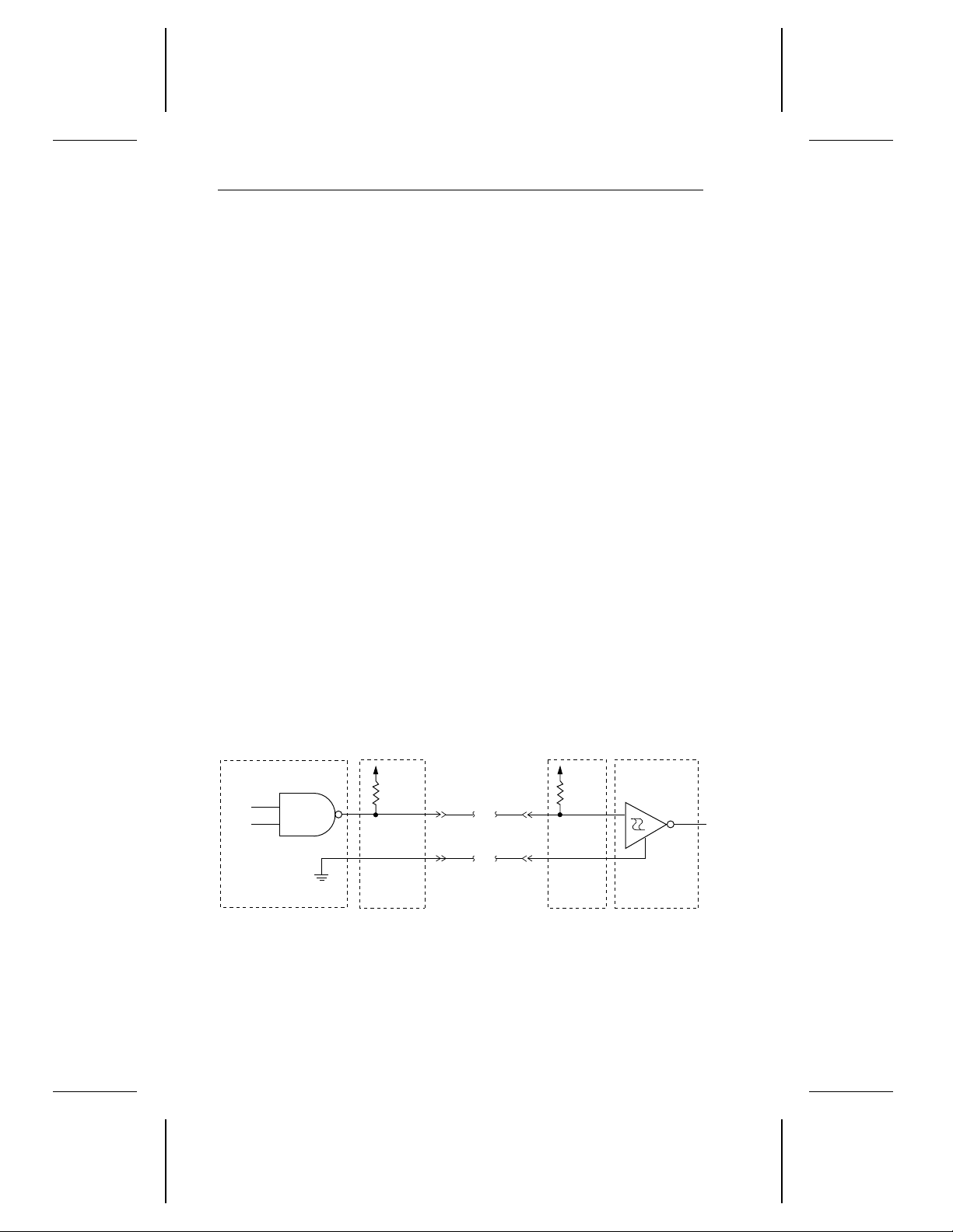
2.3 Electrical interface
The ST51080N drive is designed to use singled-ended interface signals.
They employ singled-ended drivers and receivers and active terminator
circuitry. Figure 2 shows a single-ended transmitter and receiver without
the active terminator circuitry.
• Transmitter characteristics. The drive uses an ANSI SCSI-compat-
ible, open-collector, single-ended driver. This driver is capable of
sinking a current of 48 mA with a low-level output voltage of 0.4 volts.
• Receiver characteristics. The drive uses an ANSI SCSI single-
ended receiver with hysteresis gate or equivalent as a line receiver.
The loss in the cable is defined as the difference between the voltages
of the input and output signals, as shown below:
Logic level Driver output (x) Receiver input (x)
Asserted (1)
Negated (0)
Figure 2. Single-ended transmitter and receiver
≤ x ≤ 0.4V 0.0V ≤ x ≤ 0.8V
0.0V
2.5V
≤
x ≤ 5.25V 2.0V ≤ x ≤ 5.25V
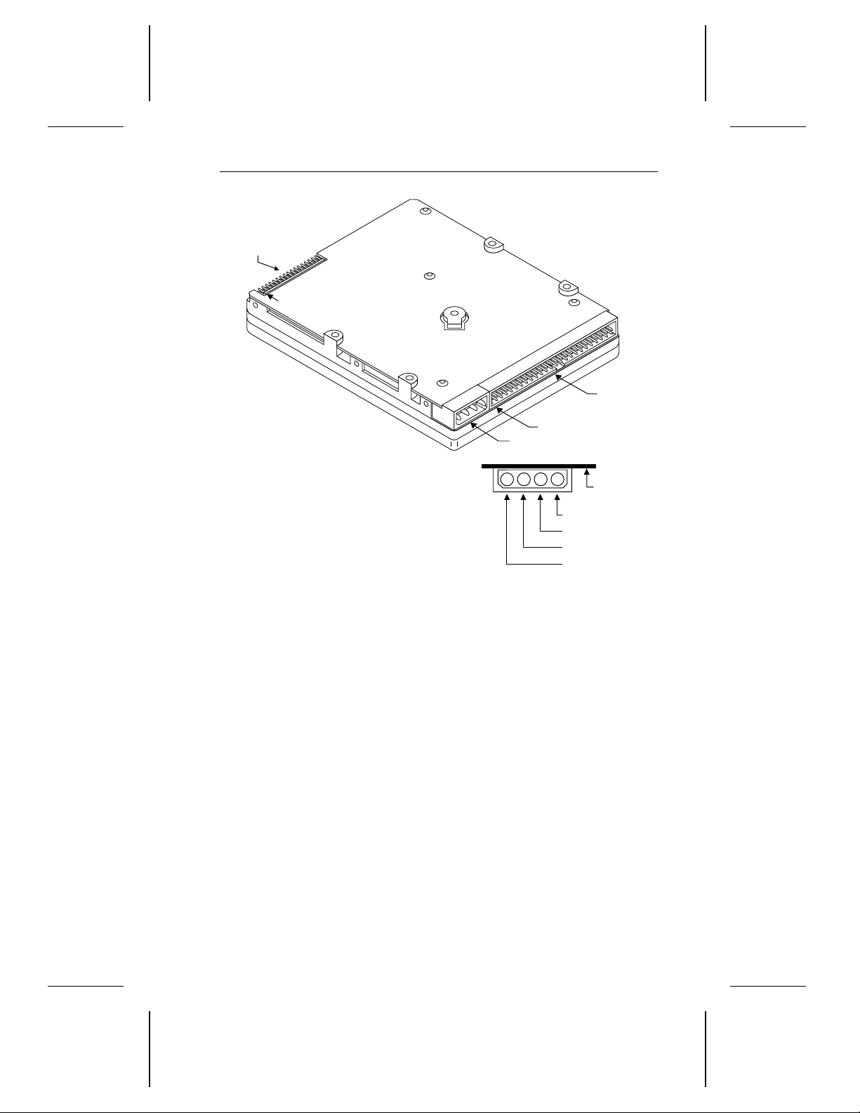
pin 1
pin 1
Standard
power connector
+5V
+5V return
+12V return
+12V
1
2
3
4
Circuit
board
Interface
connector
J8. Options
jumper block
Medalist 1080sl SCSI Product Manual, August 1995 17
Figure 3. ST51080N connectors
2.4 SCSI interface connector
The ST51080N uses a standard 50-pin, nonshielded, keyed connector.
The connector consists of two rows of 25 male contacts 0.100 inches
apart. The location of pin 1 is shown in Figure 3. Recommended mating
connectors are listed below with their part numbers.
Part numbers for mating 3M connectors compatible with the drive are
listed below. These connectors do not have a center key and are
available with or without a strain relief.
Closed end
(for cable ends)
Open end
(for daisy chain)
Without strain relief
Without center key
3M
3425-7000
3M
3425-6000
With strain relief
No center key
3M
3425-7050
3M
3425-6050

18 Medalist 1080sl SCSI Product Manual, August 1995
Part numbers for mating Molex connectors compatible with the drive are
listed below. These connectors have a center key.
Closed end
(for cable ends)
Open end
(for daisy chain)
Below are part numbers for strain reliefs that can be used with the Molex
connectors.
Molex strain relief,
preferred version
in Europe
Molex strain relief,
preferred version
in Japan
Molex
39-51-2504
Molex
39-51-2501
Molex 90170-0050
Molex 15-25-1503
2.4.1 SCSI interface connector pin assignments
The table below shows the pin assignment for the 50-pin interface
connector. A minus sign (−) indicates an active-low signal.
Signal
Signal name
DB(0)– 2 1
DB(1)– 4 3
DB(2)– 6 5
DB(3)– 8 7
DB(4)– 10 9
DB(5)– 12 11
DB(6)– 14 13
DB(7)– 16 15
DB(P)– 18 17
Ground 19–22 —
Reserved 23–25 —
Terminator power 26 —
Reserved 27–28 —
Ground 29–30 —
pin number
Ground
pin number

Medalist 1080sl SCSI Product Manual, August 1995 19
Signal
Signal name
ATN– 32 31
Ground 33–34 —
BSY– 36 35
ACK– 38 37
RST– 40 39
MSG– 42 41
SEL– 44 43
C/D– 46 45
REQ– 48 47
I/O– 50 49
Caution. Do not connect pin 25 to ground. If you plug in the connector
upside down, the terminator power on pin 26 is shorted to
ground. This may damage the drive.
pin number
Ground
pin number
2.5 Interface cable requirements
A characteristic impedance of 100 ohms +10% is recommended for the
unshielded flat or twisted-pair interface cable. However, most available
cables have a somewhat lower characteristic impedance. To minimize
discontinuities and signal reflections, do not use cables of different
impedances in the same bus. Implementation may require tradeoffs in
wielding effectiveness, cable length, the number of loads and the transfer
rates to achieve satisfactory system operation. If shielded and unshielded cables are mixed within the same bus, the effect of impedance
mismatch must be carefully considered. This is especially important for
maintaining adequate margin for Fast SCSI transfer rates.
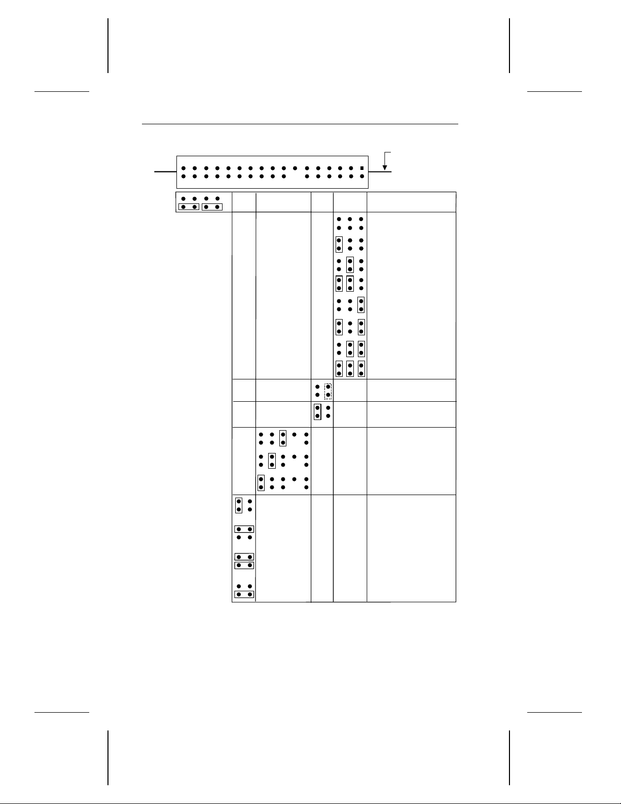
SCSI ID 0
SCSI ID 1
SCSI ID 2
SCSI ID 3
SCSI ID 4
SCSI ID 5
Note.
1. All other pins
are reserved. Do
not use them.
2. Jumpers on
pins 28 and 30
and 32 and 34
are spares; these
pins do not
require jumpers.
SCSI ID 6
SCSI ID 7
Remote LED
connection
Reserved
Do not use
Remote start
Parity enable
Terminator
disable
Power from drive
power connector
Power from
SCSI bus
Power from drive
power connector
and to SCSI bus
Power to SCSI
bus only
J8. Options jumper block
Circuit board
side up.
111291078563
4
13
14
1
2
151617
18
192021
22
3334313229302728252623
24
Spares
20 Medalist 1080sl SCSI Product Manual, August 1995
Figure 4. Options jumper block settings
 Loading...