


. . . . . . . . . . . . . . . . . . . . . . . . . . . . . . . . . . . . .
Medalist 17240, Medalist 13030
. . . . . . . . . . . . . . . . . . . . . . . . . . . . . . . . . . . . . . . . . .
Medalist 8420, Medalist 4310
. . . . . . . . . . . . . . . . . . . . . . . . . . . . . . . . . . . . . . . . . .
Ultra ATA Interface Drives
. . . . . . . . . . . . . . . . . . . . . . . . . . . . . . . . . . . . . . . . . .
. . . . . . . . . . . . . . . . . . . . . . . . . . . . . . . . . . . . . . . . . .
Product Manual
. . . . . . . . . . . . . . . . . . . . . . . . . . . . . . . . . . . . . . . . . .


. . . . . . . . . . . . . . . . . . . . . . . . . . . . . . . . . . . . . . . . . .
Medalist 17240, Medalist 13030
. . . . . . . . . . . . . . . . . . . . . . . . . . . . . . . . . . . . . . . . . .
Medalist 8420, Medalist 4310
. . . . . . . . . . . . . . . . . . . . . . . . . . . . . . . . . . . . . . . . . .
Ultra ATA Interface Drives
. . . . . . . . . . . . . . . . . . . . . . . . . . . . . . . . . . . . . . . . . .
. . . . . . . . . . . . . . . . . . . . . . . . . . . . . . . . . . . . . . . . .
Product Manual
. . . . . . . . . . . . . . . . . . . . . . . . . . . . . . . . . . . . . . . . . .

1999 Seagate Technology, Inc. All rights reserved
Publication Number: 20400134-001, Rev. A, January 1999
Seagate, Seagate Technology, the Seagate logo, Medalist and the
Medalist logo are registered trademarks of Seagate Technology, Inc.
Other product names are registered trademarks or trademarks of their
owners.
Seagate reserves the right to change, without notice, product offerings
or specifications. No part of this publication may be reproduced in any
form without written permission fro m Seagate Technology, Inc.

Medalist 17240, 13030, 8420 and 4310 Product Manual, Rev. A iii
Contents
Introduction . . . . . . . . . . . . . . . . . . . . . . . . . . . . . . . . . . . . . . . . . . . . 1
Specification summary table . . . . . . . . . . . . . . . . . . . . . . . . . . . . . . 2
1.0 Drive specifications . . . . . . . . . . . . . . . . . . . . . . . . . . . . . . . . . 5
1.1 Formatted capacity . . . . . . . . . . . . . . . . . . . . . . . . . . . . . . . . . 5
1.1.1 Default logical geometry . . . . . . . . . . . . . . . . . . . . . . . . . 5
1.1.2 Supported CHS translation geometries . . . . . . . . . . . . . 6
1.2 Physical organization . . . . . . . . . . . . . . . . . . . . . . . . . . . . . . . 6
1.3 Recording and interface technology . . . . . . . . . . . . . . . . . . . . 6
1.4 Physical characteristics . . . . . . . . . . . . . . . . . . . . . . . . . . . . . 7
1.5 Seek time . . . . . . . . . . . . . . . . . . . . . . . . . . . . . . . . . . . . . . . . 7
1.6 Start/stop times . . . . . . . . . . . . . . . . . . . . . . . . . . . . . . . . . . . . 8
1.7 Power specifications . . . . . . . . . . . . . . . . . . . . . . . . . . . . . . . . 8
1.7.1 Power consumption . . . . . . . . . . . . . . . . . . . . . . . . . . . . 8
1.7.2 Conducted noise . . . . . . . . . . . . . . . . . . . . . . . . . . . . . . 10
1.7.3 Voltage tolerance . . . . . . . . . . . . . . . . . . . . . . . . . . . . . 10
1.7.4 Power-management modes . . . . . . . . . . . . . . . . . . . . . 10
1.8 Environmental tolerances . . . . . . . . . . . . . . . . . . . . . . . . . . . 11
1.8.1 Ambient temperature . . . . . . . . . . . . . . . . . . . . . . . . . . 11
1.8.2 Temperature gradient . . . . . . . . . . . . . . . . . . . . . . . . . . 11
1.8.3 Humidity . . . . . . . . . . . . . . . . . . . . . . . . . . . . . . . . . . . . 11
1.8.4 Altitude . . . . . . . . . . . . . . . . . . . . . . . . . . . . . . . . . . . . . 12
1.8.5 Shock . . . . . . . . . . . . . . . . . . . . . . . . . . . . . . . . . . . . . . 12
1.8.6 Vibration . . . . . . . . . . . . . . . . . . . . . . . . . . . . . . . . . . . . 12
1.9 Drive acoustics . . . . . . . . . . . . . . . . . . . . . . . . . . . . . . . . . . . 13
1.10 Electromagnetic susceptibility . . . . . . . . . . . . . . . . . . . . . . . 13
1.11 Reliability . . . . . . . . . . . . . . . . . . . . . . . . . . . . . . . . . . . . . . 14
1.12 Agency certification . . . . . . . . . . . . . . . . . . . . . . . . . . . . . . . 14
1.12.1 Safety certification . . . . . . . . . . . . . . . . . . . . . . . . . . . . 14

iv Medalist 17240, 13030, 8420 and 4310 Product Manual, Rev. A
1.12.2 Electromagnetic Compatibility . . . . . . . . . . . . . . . . . . . 14
1.12.3 FCC verification . . . . . . . . . . . . . . . . . . . . . . . . . . . . . 15
2.0 Drive mounting and configuration . . . . . . . . . . . . . . . . . . . . . 17
2.1 Handling and static-discharge precautions . . . . . . . . . . . . . . 17
2.2 Jumper settings . . . . . . . . . . . . . . . . . . . . . . . . . . . . . . . . . . 17
2.2.1 Master/slave configuration . . . . . . . . . . . . . . . . . . . . . . 17
2.2.2 Alternate capacity jumper . . . . . . . . . . . . . . . . . . . . . . . 17
2.3 Drive mounting . . . . . . . . . . . . . . . . . . . . . . . . . . . . . . . . . . . 18
3.0 ATA interface . . . . . . . . . . . . . . . . . . . . . . . . . . . . . . . . . . . . . . 21
3.1 ATA interface signals and connector pins . . . . . . . . . . . . . . 21
3.2 ATA Interface commands . . . . . . . . . . . . . . . . . . . . . . . . . . . 23
3.2.1 Supported ATA commands . . . . . . . . . . . . . . . . . . . . . . 23
3.2.2 Identify Drive command . . . . . . . . . . . . . . . . . . . . . . . . 25
3.2.3 Set Features command . . . . . . . . . . . . . . . . . . . . . . . . . 29
3.2.4 S.M.A.R.T. commands . . . . . . . . . . . . . . . . . . . . . . . . . 30

Medalist 17240, 13030, 8420 and 4310 Product Manual, Rev. A v
Figures
Figure 1. Typical startup and operation current profile . . . . . . . . . . . . 9
Figure 2. Alternate capacity jumper and master/slave jumper . . . . . 18
Figure 3. Mounting dimensions—top, side and end view . . . . . . . . . 19
Figure 4. I/O pins and supported ATA signals. . . . . . . . . . . . . . . . . . 22

vi Medalist 17240, 13030, 8420 and 4310 Product Manual, Rev. A

Medalist 17240, 13030, 8420 and 4310 Product Manual, Rev. A 1
Introduction
This manual describes the functional, mechanical and interface specifications for the Medalist
(ST313030A), Medalist 8420 (ST38420A) and the Medalist 4310
(ST34310A). These drives are referred to throughout this manual by their
model numbers. These drives provide the following key features:
Low power consumption
•
Quiet operation
•
Support for S.M.A.R.T. drive monitoring and reporting
•
High instantaneous (burst) data-transfer rates (up to 33.3 Mbytes per
•
second) using Ultra DMA mode 2
Full-track multiple-sector transfer capability without local processor
•
intervention
512-Kbyte cache
•
State-of-the-art cache and on-the-fly error-correction algorithms
•
Support for Read Multiple and Write Multiple commands
•
Support for autodetection of master/slave drives that use cable select
•
(CSEL)
These drives use MR recordi ng heads and PRML technology , which
•
provide the drives with increased areal density.
17240 (ST317240A), Medalist 13030
2 Medalist 17240, 13030, 8420 and 4310 Product Manual, Rev. A
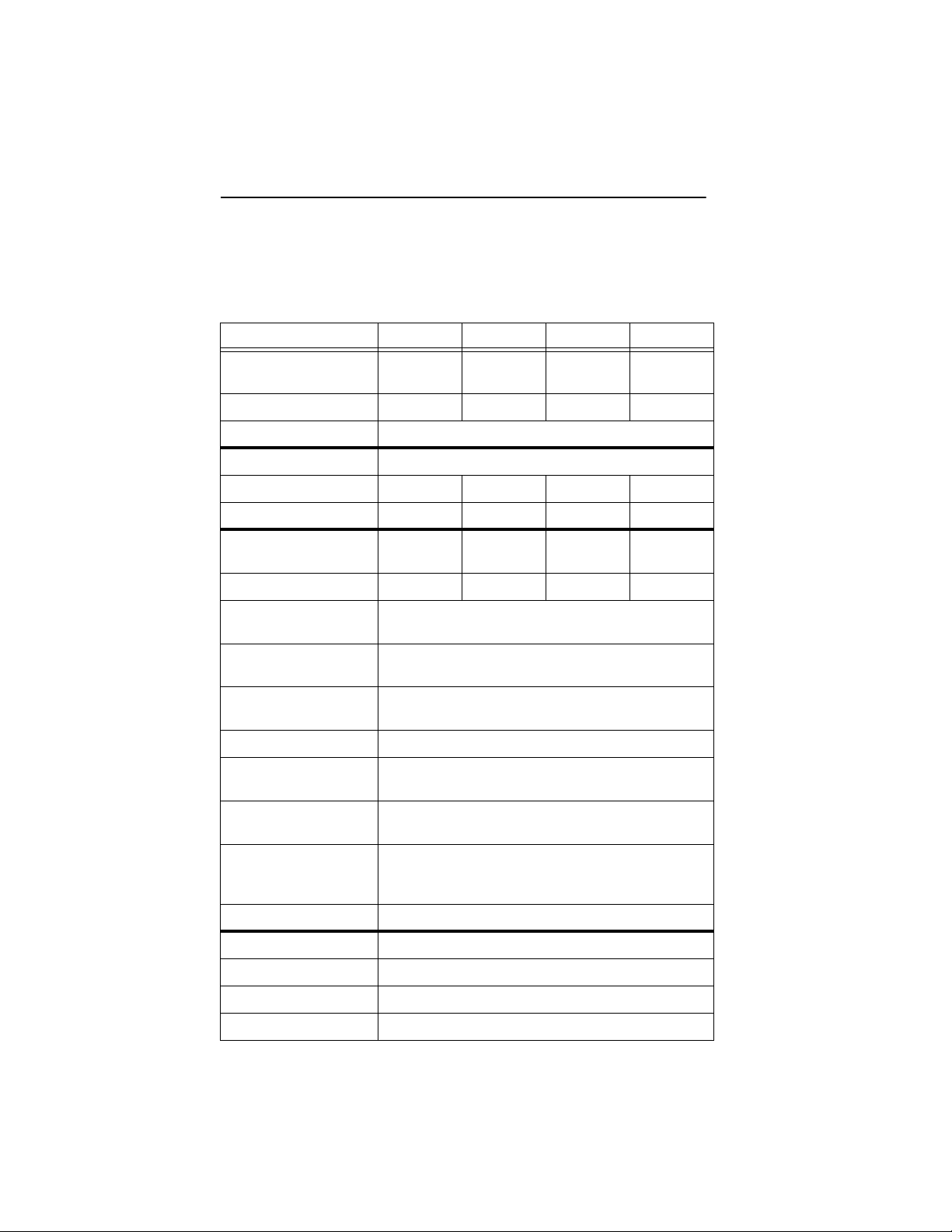
Specification summary table
The specifications listed in this table are for quick reference. For details
on specification measurement or definition, see the appropriate section
of this manual.
Drive Specification ST317240A ST313030A ST38420A ST34310A
Guaranteed Mbytes
6
(×10
bytes)
Guaranteed sectors 33,683,328 25,434,228 16,841,664 8,420,832
Bytes per sector 512
Default sectors per track 63
Default read/write heads 16 16 16 16
Default cylinders 16,383 16,383 16,383 8,354
Physical read /write
heads 8642
Discs 4321
Recording density
(bits/inch max) 234,000
Track density
(tracks/inch) 13,405
Areal density
(Mbits/inch
Spindle speed (RPM) 5,400
Internal data-transfer
rate (Mbits/sec max)
2
)3,146
17,245 13,022 8,622 4,311
171
I/O data-transfer rate
(Mbytes/se c ma x)
ATA data-transfer modes
supported
Cache buffer (Kbytes) 512
Height (mm max) 26.10
Width (mm max) 101.85
Length (mm max) 147.00
Weight (grams typical) 544
PIO modes 0, 1, 2, 3, 4;
Multiword DMA modes 0, 1, 2;
Ultra DMA modes 0, 1, 2
33.3
Medalist 17240, 13030, 8420 and 4310 Product Manual, Rev. A 3
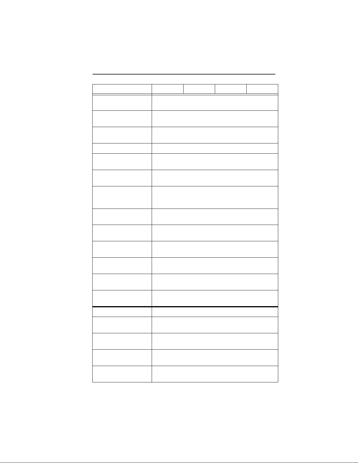
Drive Specification ST317240A ST313030A ST38420A ST34310A
Track-to-track seek time
(msec typical) 1.5
Average seek time
(msec typical) 9.0
Full-stroke seek time
(msec typical) 16.5
Average latency (msec) 5.6
Power-on to ready
(sec typical) 12
Standby to ready
(sec typical) 12
Startup current:
12V (peak)
5V (peak)
2.2 amps
0.72 amps
Seek power and cu rrent
(mean)
Read/Write power and
current (typical) 6.6 watts
Idle mode power and
current (typical) 5.5 watts
Standby mode power
and current (typical) 1.1 watts
Sleep mode power and
current (typical) 1.1 watts
Voltage tolerance
(including noise)
Ambient temperature 5° to 55°C (op.), –40° to 70°C (nonop.)
Temperature gradient
(per hour max) 20°C
Relative humidity
(op. and nonop.)
Relative humidity
gradient 10% per hour max
Wet bulb temperature
(max) 29.4°C (op.), 29.4°C (nonop.)
8% to 90% (op.)
5% to 95% (nonop.)
10.3 watts
5V ± 5%
12V ± 10%
4 Medalist 17240, 13030, 8420 and 4310 Product Manual, Rev. A
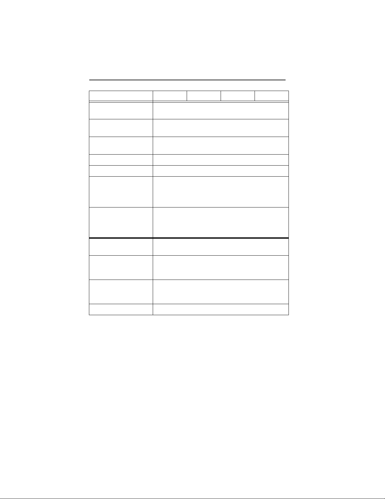
Drive Specification ST317240A ST313030A ST38420A ST34310A
Altitude (meters below
mean sea level, max)
–122 to 3,048 (op.)
–122 to 12,192 (nonop.)
Shock, operating
(Gs max at 2 msec) 15
Shock, nonoperating
(Gs max at 2 msec) 300
Vibration, operating 0.50 G (0 to peak, 22–350 Hz)
Vibration, nonoperating 5.0 Gs (0 to peak, 22–350 Hz)
Drive acoustics
(bels—sound power)
3.5 (typical), 3.9 (max)
Idle mode
(dBA—sound pressure)
Drive acoustics
(bels—sound power)
30 (typical )
4.0 (typical), 4.3 (max)
Read/Write mode
(dBA—sound pressure)
Nonrecoverable read
errors 1 per 10
32 (typical )
14
bits read
Mean time between
failures (pow e r-on
400,000
hours)
Contact start-stop cycles
(25°C, 40% relative
40,000
humidity)
Service life (years) 5

Medalist 17240, 13030, 8420 and 4310 Product Manual, Rev. A 5
1.0 Drive specifications
Unless otherwise noted, all specifications are measured under ambient
conditions, at 25 °C, and no min al power. For convenie nce, the phrases
the drive
ST317240A, ST313030A, ST38420A and the ST34310A.
1.1 Formatted capacity
and
this drive
are used throughout this manu al to indi cate the
Drive
Model
ST317240A 17,245 33,683,328 512
ST313030A 13,022 25,434,228 512
ST38420A 8,622 16,841,664 512
ST34310A 4,311 8,420,832 512
Note.
DOS systems ca nnot access more than 52 8 Mbytes o n a drive
unless 1) the host system supp orts and is configured for LBA
addressing or for extended CHS addressing, 2) the host system
contains a specialized drive controller, or 3) the host system runs
BIOS translation software. Contact your Seagate
for details.
Guaranteed Mbytes
(1 Mbyte = 10
6
bytes)
Guaranteed
sectors
Bytes per
sector
®
representative
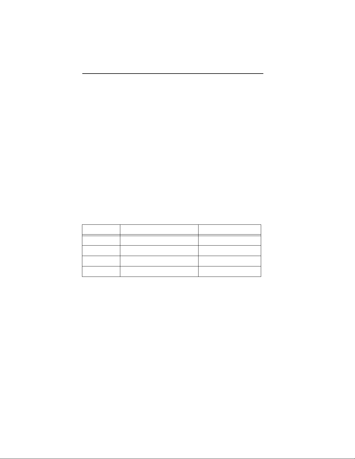
1.1.1 Default logical geometry
CHS Mode Cylinders Read/Write heads Sectors per track
ST317240A 16,383 16 63
ST313030A 16,383 16 63
ST38420A 16,383 16 63
ST34310A 8,354 16 63
LBA Mode
When addressing either drive in LBA mode, all blocks (sectors) are
consecutively numbered from 0 to
guaranteed sectors as defined above
n–1,
.
where
n is
the number of
6 Medalist 17240, 13030, 8420 and 4310 Product Manual, Rev. A
1.1.2 Supported CHS translation geometries
These drives support any tr anslation geometry that satis fies
following conditions:
•
Sectors per track ≤ 63
•
Cylinders ≤ 16,383 (for drives over 8.4 Gbytes)
•
Read/Write heads ≤ 16
The ST317240A logical cylinders are:
Logical cylinders=33,683,328/(logical sectors per track × logical heads)
The ST313030A logical cylinders are:
Logical cylinders=25,434,228/(logical sectors per track × logical heads)
The ST38420A logical cylinders are:
Logical cylinders=16,841,664/(logical sectors per track × logical heads)
The ST34310A logical cylinders are:
Logical cylinders=8,420,832/(logical sectors per track × logical heads)
all
of the
1.2 Physical organization
Drive Model Read/Write heads (MR) Number of discs
ST317240A 8 4
ST313030A 6 3
ST38420A 4 2
ST34310A 2 1
1.3 Recording and interface technology
Interface ATA
Recording method EPRML (16,17)
Recording density
(bits/inch)
Track density (tracks/inch) 13,405
Areal density (Mbits/inch
Spindle speed (RPM)
( ± 0.2%)
Internal data-transfer rate
(Mbits per second max)
234,000
2
)3,146
5,400
171

Medalist 17240, 13030, 8420 and 4310 Product Manual, Rev. A 7
I/O data-transfer rate
(Mbytes per second max)
Interleave 1:1
Cache buffer (Kbytes) 512
16.6 (PIO mode 4 with IORDY)
16.6 (multiword DMA mode 2)
33.3 (Ultra DMA mode 2)
1.4 Physical characteristics
Drive Specification ST317240A, ST313030A,
ST38420A, ST34310A
Maximum height (mm)
(inches)
Maximum width (mm)
(inches)
Maximum length (mm)
(inches)
Typical weight (grams)
(pounds)
26.10
1.028
101.85
4.010
147.00
5.787
544
1.2
1.5 Seek time
The measurements are taken with nominal power at 25°C ambient
temperature. All times are measured using drive diagnostics. The specifications in the table below are defined as follows:
•
Track-to-track seek time is an average of all possible single-track
seeks in both directions.
•
Average seek time is a true statistical random average of at least 5,000
measurements of seeks between random tracks, less overhead.
•
Full-stroke seek time is one-half the time needed to seek from the first
data cylinder to the maximum data cylind er an d b ac k t o th e fi rst dat a
cylinder. The full-stroke typic al v al ue is determined by averaging 100
full-stroke seeks in both directions.
Seek type (msec, typical)
Track-to-track 1.5
Average 9.0
Full-stroke 16.5
Average latency: 5.6 msec

8 Medalist 17240, 13030, 8420 and 4310 Product Manual, Rev. A
Note. These drives are design ed to consis tently meet the s eek times
represented in th is m anu al. P hy si cal se ek s, r ega r dle ss of mode
(such as track-to-track and average) are expected to meet or
exceed the noted values. Due to the manner in which these drives
are formatted, however, benchmark tests that include command
overhead or that measure logical seeks may produce results that
vary from these specifications.
1.6 Start/stop times
Power-on to Ready (sec) 12 (typical)
Standby to Ready (sec) 12 (typical)
Ready to spindle stop (sec) 12 (typical)
1.7 Power specifications
The drive receives DC power (+5V or +12V) through a four-pin standard
drive power connector.
1.7.1 Power consumption
Power requirements for the drives are listed in the table on pag e 9.
Typical power measurements are based on an average of drives tested,
under nominal conditions, using 5.0V input voltage at 25°C ambient
temperature.
Spinup peak current is the peak current measured from the time of
power-on to the time that the drive spindle reaches operating speed.
During Seek mode, the read/write actuator arm moves toward a specific
position on the disc surface and does not execute a read or write
operation. Servo electron ics are active. Seek mode pow er represents
the worst-case power consumption, using only random seeks with read
or write latency time. This mode is not typical and is provided for worstcase information.
Read/Write power an d current are me asured with t he heads on trac k,
based on a 16-sector write followed by a 32-msec delay, then a 16-sector
read followed by a 32-msec delay.
Operating power and cur rent are measured using 40 percent random
seeks, 40 percent read/wr ite mode (1 write for each 10 reads) , and 20
percent drive inactive.
Idle mode power is measur ed with the drive up to speed, with servo
electronics active, and with the heads in a random track location.

Medalist 17240, 13030, 8420 and 4310 Product Manual, Rev. A 9
During Standby mode, the drive accepts commands, but the drive is not
spinning, and the s ervo and read/write electro nics are in power-down
mode.
Mode Typical Watts RMS Typical Amps RMS
5V 12V
Spinup — 0.72 (Peak) 2.2 (Peak)
Seek
10.3 0.50 0.65
(Random,
no read/write)
Read/Write 6.7 0.675 0.275
Operating 6.7 0.675 0.275
Idle 5.5 0.5 0.25
Standby 1.1 0.22 —
Sleep 1.1 0.22 —
1.7.1.1 Typical current profile
Figure 1 shows a typical current profile.
Current (Amps)
2.0
1.5
1.0
0.5
0
0
18765432
Time (seconds)
Figure 1. Typical startup and operation current profile
9

10 Medalist 17240, 13030, 8420 and 4310 Product Manual, Rev. A
1.7.2 Conducted noise
Input noise ripple i s mea su re d a t the host system powe r su ppl y ac ross
an equivalent 80-ohm resistive load on the +12 volt line or an equivalent
15-ohm resistive load on the +5 volt line.
•
Using 12-volt power, the drive is expected to operate with a maximum
of 120 mV peak-to-peak square-wave injected noise at up to 10 MHz.
•
Using 5-volt power, th e dri ve is expec ted to op er ate with a ma xi mum
of 100 mV peak-to-peak square-wave injected noise at up to 10 MHz.
Note.
Equivalent resis tance is calcu lated by dividing the nomina l voltage by the typical RMS read/write current.
1.7.3 Voltage tolerance
Voltage tolerance (including noise): 5V ± 5% and 12V ± 10%
1.7.4 Power-management modes
These drives provide programmable power management to provide
greater energy efficiency. In most systems, you can control power
management through the system setup program. These Seagate drives
feature several power -management modes, which are summarized in
the following table and described in more detail below:
Mode Heads S pindle Buffer
Active Tracking Rotating Enabled
Idle Tracking Rotating Enabled
Standby Parked Stopped Enabled
Sleep Parked Stopped Disabled
Active mode
operations.
Idle mode
commands and returns to Active mode any time disc access is
necessary.
. The drive is in Active mode during the read/write and seek
. The buffer remains enabled, and the drive accepts all
Standby mode
Standby Immediate command. If the host has set the standby timer, the
drive can also enter Standby mode automatically after the drive has been
inactive for a specifiable length of time. The standby timer delay is
established using a Standby or Idle command. In Standby mode, the
heads are parked and the spindle is at rest. The drive accepts all
commands and returns to Active mode any time disc access is necessary.
. The drive enters Standby mode when the host sends a

Medalist 17240, 13030, 8420 and 4310 Product Manual, Rev. A 11
Sleep mode. The drive enters Sleep mode after receiving a Sleep
command from the host. The heads are parked and the spindle is at rest.
The drive leaves Sleep mode after it receives a Hard Reset or Soft Reset
from the host. After rec eiving a reset, the driv e exits Sleep mode and
enters Active mode with all current translation parameters intact.
Idle and Standby timers. Each time the drive performs an Active
function (read, write or seek), the standby timer is reinitialized and begins
counting down from its specified delay times to zero. If the standby timer
reaches zero before a ny drive activity is required , the drive makes a
transition to Standb y mode. In both Idle and Standby mod e, the drive
accepts all commands and r etur ns to Ac tive mode when disc access is
necessary.
1.8 Environmental tolerances
1.8.1 Ambient temperature
Operating 5° to 55°C (41° to 131°F)
Nonoperating –40° to 70°C (–40° to 158°F)
Note. Above 1,000 feet (305 meters), the maximum temperature is
derated linearly to 1 12°F (44°C) at 10,000 feet (3,048 meters) .
Operating ambient temperature is defined as the temperature of
the environment immediately surrounding the drive.
1.8.2 Temperature gradient
Operating 20°C/hour (36°F/hour) max, without condensation
Nonoperating 20°C/hour (36°F/hour) max, without condensation
1.8.3 Humidity
1.8.3.1 Relative Humidity
Operating 8% to 90% noncondensing (10% per hour max)
Nonoperating 5% to 95% noncondensing (10% per hour max)
1.8.3.2 Wet bulb temperature
Operating 29.4°C (84°F) max
Nonoperating 29.4°C (84°F) max

12 Medalist 17240, 13030, 8420 and 4310 Product Manual, Rev. A
1.8.4 Altitude
Operating –122 m to 3,048 m (–400 ft to 10,000+ ft)
Nonoperating –122 m to 12,192 m (–400 ft to 40,000+ ft)
1.8.5 Shock
During shock tests, the drive was mounted securely with the input shock
applied at the drive mounting screws. Shock may be applied in the X, Y
or Z axis.
1.8.5.1 Operating shock
These drives comply with the performance levels specified in this document when subjected to a maximum operating shock of 15.0 Gs (based
on half-sine shock pulses o f 11 msec). Sh ocks are not to be repeate d
more than two times per second.
1.8.5.2 Nonoperating shock
The nonoperating shock level that the drive can experience without
incurring physical damage or degradation in performance when subsequently put into operation is 300 Gs (bas ed on nonrepetitive half-sine
shock pulse of 2 m sec duration). S hock pulse is def ined by MIL-STD202F.
1.8.6 Vibration
During vibration te sts, the drive was mounted securely with the input
vibration applied at the drive mounting screws. Vibration may be applied
in the X, Y or Z axis.
1.8.6.1 Operating vibration
The following table lists the maximum vibration levels that the drive may
experience while mee ting the performance sta ndards specified in this
document.
5–22 Hz 0.020-inch displacement (peak to peak)
22–350 Hz 0.50 Gs acceleration (zero to peak)

Medalist 17240, 13030, 8420 and 4310 Product Manual, Rev. A 13
1.8.6.2 Nonoperating vibration
The following table lis ts the maximum nonoperating v ibration that the
drive may experience without incurring physical damage or degradation
in performance when subsequently put into operation.
5–22 Hz 0.20-inch displacement (peak to peak)
22–350 Hz 5.0 Gs acceleration (zero to peak)
1.9 Drive acoustics
Drive acoustics were measu red as overall A-weighted ac oustic sound
power levels. All measurements are generally consistent with ISO document 7779. Sound power measurements were taken under essentially
free-field conditions over a reflecting plane. For all tests, the worst case
drive is considered, either cover up or cover down.
For the Seek mode, the drive was placed in seek only. Currently for these
drives, the approximate number of seeks per second is 26.6. The number
of seeks per second is defined by the following equation:
Number of seeks per second = 0.4 / (average latency + average access time)
Typical sound
Mode
Idle 3.5 3.9
Read/Write 4.0 4.3
power (bels)
Maximum sound
power (bels)
1.10 Electromagnetic susceptibility
The drive operates without errors when subjected to the following:
Radiated noise ≤ 3 volt/meter, 30 Hz to 500 MHz
Electrostatic discharge * ≤ 10 KVolts
Magnetic field strength ≤ 5 Gauss
* Electrostatic discharge susceptibility is measured with the drive
mounted in a representative computer system (mounted to a ground
plane with earth grounding). Discharges are applied to the bezel or
other external surfaces on the ground plane.
.

14 Medalist 17240, 13030, 8420 and 4310 Product Manual, Rev. A
1.11 Reliability
14
Nonrecoverable read errors 1 per 10
Mean time between failures 400,000 power-on hours
(nominal power, 25°C ambient temperature)
Contact start-stop cycles 40,000 cycles
(at nominal voltage and temperature,
with 60 cycles per hour and a 50%
duty cycle)
Preventive maintenance None required
bits read, max
1.12 Agency certification
1.12.1 Safety certification
The drives are recognized in accordance with UL 1950 and CSA C22.2
(950) and meet all applicable sections of IEC950 and EN 60950 as tested
by TUV North America.
1.12.2 Electromagnetic Compatibility
Hard drives that display the CE marking comply with European Unio n
requirements specified in Electromagnetic Compatibility Directives.
Testing is performed to standards EN50082-1 and EN55022-B.
Seagate uses an independent laboratory to confirm compliance with the
EC directives speci fied in t he previous p aragrap h. Drives are tested in
representative end-user systems. Although CE-marked Seagate drives
comply with the dir ectives when used in the t est systems, we cannot
guarantee that all sy stems will c omply with the d irectives. Th e drive is
designed for operation inside a properly designed enclosure, with properly shielded I/O cable (if necessary) and terminators on all unused I/O
ports. Computer manuf acturers and system integrato rs should confirm
EMC compliance and provide CE marking for their products.
Australian C-Tick
If these models have the C-Tick marking, they comply with the Australia/
New Zealand Standard AS/NZS 3548 1995 and meet the Electrom agnetic Compatibility (EMC) Framework requirements of Australia’s Spectrum Management Agency (SMA).

Medalist 17240, 13030, 8420 and 4310 Product Manual, Rev. A 15
1.12.3 FCC verification
These drives are intended to be contained solely within a personal
computer or similar enclos ure (n ot attac hed as a n exte rnal dev ice ). As
such, each drive is considered to be a subassembly even when it is
individually mar keted to the customer. As a subassembly, no Federal
Communications Commission verification or certification of the device is
required.
Seagate Technology, Inc. has tested this devi ce in enclosures as described above to ensure th at the total assem bly (enclo sure, disc drive,
motherboard, power supply, etc.) does comply with the limits for a Class
B computing devi ce, pursuant to Subp art J, Part 15 of the FCC rules.
Operation with noncertified as sembl ies is likel y to resu lt in interfe rence
to radio and television re ception.
Radio and Television Interference.
uses radio frequency energy and if not installed and used in strict
accordance with the manufacturer’s instructions, may cause interference to radio and television reception.
This equipment is desig ned to provide reasonable protection against
such interference in a residential installation. However, there is no
guarantee that interfer ence will not occur in a particu lar installation. If
this equipment does cause interference to radio or television, which can
be determined by turning the equipment on and off, you are encouraged
to try one or more of the following corrective measures:
•
Reorient the receiving antenna.
•
Move the device to one side or the other of the radio or TV.
•
Move the device farther away from the radio or TV.
•
Plug the computer into a different outlet so that the receiver and
computer are on different branch outlets.
If necessary, you s hould consult your de aler or an experienced radio/
television technician for additional suggestions. You may find helpful the
following booklet pr epared by the Federal Communications Com mis-
How to Identify and Resolve Radi o-Television Interfer ence Prob-
sion:
. This booklet is available from the Supe rintendent of Doc uments,
lems
U.S. Government Printing Office, Washington, DC 20402. Refer to publication number 004-000-00345-4.
This equipment generates and

16 Medalist 17240, 13030, 8420 and 4310 Product Manual, Rev. A

Medalist 17240, 13030, 8420 and 4310 Product Manual, Rev. A 17
2.0 Drive mounting and configuration
2.1 Handling and static-discharge precautions
After unpacking, and before installation, the drive may be exposed to
potential handling and electrostatic discharge (ESD) hazards. Observe
standard static-discharge precautions. A grounded wrist-strap is preferred.
Handle the drive o nly by the sides of the head/disc assembly. Avoid
contact with the printed circuit board, all electronic components and the
interface connector. Do not apply pressure to the top cover of the drive.
Always rest the drive on a padded antistatic surface until you mount it in
the host system.
2.2 Jumper settings
2.2.1 Master/slave configuration
You must establish a master/slave relationship between two drives that
are attached to a single AT bus. You can configure a drive as a master
or slave by setting the master/slave jumpers, shown in Figure 2 on page
18.
These drives support mas ter /s lave c on f ig urati on u si ng t he c abl e s el ect
option. This requi res a special daisy-chai n cable that grounds pin 28
(CSEL) on one of its two drive connectors. If you attach the drive to the
grounded CSEL conn ector, i t is a ma ster . If y ou atta ch the drive to th e
ungrounded CSEL con nector, it is a sl ave. To us e this optio n, the h ost
system and both drives must support cable select, and both drives must
be configured for c able select. To con figure this drive for cabl e select,
install a jumper as shown in Figure 2.
For the master drive to recognize the slave drive using the DASP– signal,
the slave drive must assert the DASP– signal at power up, and the
master drive must monitor DASP– at power up.
2.2.2 Alternate capacity jumper
Some older computers may “hang” if their BIOS detects a hard drive that
has more than 4,092 cyl inders at sta rtup. To allow th ese compu ters to
recognize the ST317240A , ST313030A, ST38420A or the S T34310A,
these drives include a capacity-limiting jumper, which sets the drive’s
default translation g eometry to 4,092 cylinders. This lim its the drive’s
capacity to 2.1 Gbytes, unless third-party software is used.

18 Medalist 17240, 13030, 8420 and 4310 Product Manual, Rev. A
ATA interface
connector
pin 1
24
8
Alternate capacity and master/slave
jumper settings
1.
The drive is shipped with a jumper on pins 7
and 8. This configures the drive for master or
single drive operation.
2. Consult your computer manual to determine
whether your computer supports cable select.
3. Use this jumper setting
not work with a jumper on pins 7 and 8.
4. Use this jumper setting if your computer fails
to boot because it cannot recognize drives with
more than 4,092 cylinders.
only
if the drive does
4-pin power
connector
Slave
Master or single drive
Enable cable select
Master with non-ATA
compatible slave
Limit capacity to 2.1 Gbytes
(4,092 cylinders)
1
2
3
4
135
6
7
Figure 2. Alternate capacity jumper and master/slave jumper
2.3 Drive mounting
You can mount the drive in any orientation using four screws in the sidemounting holes or four screws in the bottom-mounting holes. See Figure
3 for drive mounting dimensions.
Important mounting precautions:
•
Allow a minimum clearanc e of 0.030 inches (0.76 mm) around the
entire perimeter of the drive for cooling.
•
Use only 6-32 UNC mounting screws.
•
The screws should be inserted no more than 0.22 inch (5.58 mm) into
the bottom mounting holes and no more than 0.20 inch (5.0 mm) into
the side mounting holes.
•
Do not overtighten the mou nti ng s cre ws (m ax im um t orque : 3 i nc h- lb,
0.34 N.m, 3.45 kgf.cm) .
•
Do not use a drive interface cable more than 18 inches (457 mm) long.

Medalist 17240, 13030, 8420 and 4310 Product Manual, Rev. A 19
Note. Dimensions are shown in mm (inches)
94.3 ± 0.8
[3.71 ± 0.03]
71.8 ± 0.8
[2.83 ± 0.03]
56.5 ± 0.8
[2.23 ± 0.03]
26.10 MAX
[1.028]
147.00 MAX
[5.787]
3X 6.35 ± 0.31
[0.250 ± 0.012]
BOTH SIDES
5.83 ± 0.38
[0.230 ± 0.015]
27.90 ± 0.27
[1.098 ± 0.011]
41.60 ± 0.33
[1.638 ± 0.013]
101.60 ± 0.33
[4.000 ± 0.013]
3X 6-32 UNC 2B
MAX INSERTION DEPTH
0.20 (5.0 mm) BOTH SIDES
4X 6-32 UNC 2B
MAX INSERTION
DEPTH 0.22 (5.6 mm)
PIN ONE J2
0.27
±
40.77
0.011]
[1.605 ±
44.45 ± 0.33
[1.750 ± 0.013]
PIN ONE J3
[0.125 ± 0.011]
PIN ONE J4
[3.750 ± 0.014]
3.18 ± 0.27
95.24
101.85 MAX
[4.010 MAX]
Figure 3. Mounting dimensions—top, side and end view
4.66 ± 0.38
[0.183 ± 0.015]
±
0.35

20 Medalist 17240, 13030, 8420 and 4310 Product Manual, Rev. A

Medalist 17240, 13030, 8420 and 4310 Product Manual, Rev. A 21
3.0 ATA interface
These drives use the industry-standard ATA task file interface that
supports 16-bit data transfers. It supports ATA programmed input/output
(PIO) modes 0, 1, 2, 3 a nd 4; multiword DMA modes 0, 1 and 2; an d
Ultra DMA modes 0, 1 and 2. The drive also supp orts the use of the
IORDY signal to provide reliable high-speed data transfers.
You can use a da isy-chain ca ble to connect two drives to a single AT
host bus. For detailed info rmati on abou t the ATA interf ace, ref er to the
draft of
NCITS T13 1153D,
dard
3.1 ATA interface signals and connector pins
Figure 4 on page 22 summarizes the signals on the ATA interface
connector that the drive supports. For a detailed des cription of these
signals, refer to the
AT Attachment with Packet Interface Extension (ATA/ATAPI-4),
subsequently referr ed to as the
.
Draft ATA-4 Standard.
Draft ATA-4 Stan-

22 Medalist 17240, 13030, 8420 and 4310 Product Manual, Rev. A
Drive pin #
10
11
12
13
14
15
16
17
18
19
20
21
22
23
24
25
26
27
28
29
30
31
32
33
34
35
36
37
38
39
40
Signal name
–
1
2
3
4
5
6
7
8
9
Reset
Ground
DD7
DD8
DD6
DD9
DD5
DD10
DD4
DD11
DD3
DD12
DD2
DD13
DD1
DD14
DD0
DD15
Ground
(removed)
DMARQ
Ground
DIOW–
STOP
Ground
DIOR
HDMARDY
DDMARDY–
–
HSTROBE
Ground
IORDY
DSTROBE
CSEL
DMACK
Ground
INTRQ
IOCS16
DA1
–
PDIAG
DA0
DA2
–
CS0
–
CS1
–
DASP
Ground
–
–
–
Host pin # and signal description
1
Hardware Reset
2
Ground
3
Host Data Bus Bit 7
4
Host Data Bus Bit 8
5
Host Data Bus Bit 6
6
Host Data Bus Bit 9
7
Host Data Bus Bit 5
8
Host Data Bus Bit 10
9
Host Data Bus Bit 4
10
Host Data Bus Bit 11
11
Host Data Bus Bit 3
12
Host Data Bus Bit 12
13
Host Data Bus Bit 2
14
Host Data Bus Bit 13
15
Host Data Bus Bit 1
16
Host Data Bus Bit 14
17
Host Data Bus Bit 0
18
Device Data (15:0)
19
Ground
(No Pin)
20
21
DMA Request
22
Ground
23
Device I/O Write:
Stop Ultra DMA Burst
24
Ground
25
Device I/O Read:
Host Ultra DMA Ready:
Host Ultra DMA Data Strobe
26
Ground
27
I/O Channel Ready
Device Ultra DMA Ready
Device Ulta DMA Data Strobe
28
Cable Select
29
DMA Acknowledge
30
Ground
31
Device Interrupt
32
Reserved
33
Host Address Bus Bit 1
34
Passed Diagnostics
35
Device Address (2:0)
36
Device Address (2:0)
37
Chip Select (1:0)
38
Chip Select (1:0)
39
Drive Active/Slave Present
40
Ground
Pins 28, 34 and 39 are used for master-slave communication (details shown below).
28
34
39
Drive 0 (master)Drive 1 (slave)
28
34
39
CSEL
PDIAG
DASP–
–
Host
28
34
39
Figure 4. I/O pins and supported ATA signals

Medalist 17240, 13030, 8420 and 4310 Product Manual, Rev. A 23
3.2 ATA Interface commands
3.2.1 Supported ATA commands
The following table lis ts ATA-standard commands that the driv e supports. For a detailed description of the ATA commands, refer to the
ATA-4 Standard.
See Section 3.2.4 on page 30 for details and subcom-
mands used in the S.M.A.R.T. implementation.
Draft
Command
Command name
code
ATA-standard commands
Download Microcode 92
Execute Device Diagnostics 90
Flush Cache E7
Format Track 50
Identify Device EC
Initialize Device Parameters 91
Read Buffer E4
Read DMA C8
H, C9H
Read Multip le C4
Read Sectors 20
Read Verify Sectors 40
H, 21H
H, 41H
Recalibrate 10
Supported by
ST317240A, ST313030A,
ST38420A, ST34310A
H
H
H
H
H
H
H
Yes
Yes
Yes
Yes
Yes
Yes
Yes
Yes
H
Yes
Yes
Yes
H
Yes
Seek 70
Set Features EF
Set Multiple Mode C6
S.M.A.R.T. B0
Write Buffer E8
Write DMA CA
H, CBH
H
H
H
H
H
Yes
Yes
Yes
Yes
Yes
Yes

24 Medalist 17240, 13030, 8420 and 4310 Product Manual, Rev. A
Command
Command name
Write Multiple C5
Write Sectors 30
code
H
H, 31H
ATA-standard power-management commands
Check Power Mode 98
Idle 97
or E5
H
or E3
H
Idle Immediate 95H or E1
Sleep 99
Standby 96
or E6
H
or E2
H
Standby Immediate 94H or E0
Supported by
ST317240A, ST313030A,
ST38420A, ST34310A
Yes
Yes
H
H
H
H
H
H
Yes
Yes
Yes
Yes
Yes
Yes

Medalist 17240, 13030, 8420 and 4310 Product Manual, Rev. A 25
The following commands contain drive-specific features that may not be
described in the
Draft ATA-4 Standard
.
3.2.2 Identify Drive command
The Identify Drive command (command code ECH) transfer s information
about the drive to the host following power up. The data is organized as
a single 512-byte bl ock of data, whose contents are shown in the tabl e
below. All reserved bits or words should be set to zero. Parameters listed
with an “x” are drive-specific or vary with the state of the drive. See drive
specifications in Section 1 of this manual for default parameter settings.
Note.
If the alternate capacity j umper is install ed on these drives , the
drive capacity is reduced in word 1 to 4,092 cylinders.
Word Description Value
Configuration information:
•
Bit 15: 0 = ATA; 1 = ATAPI
•
0
1 Number of logical cylinders:
Bit 7: removable media
•
Bit 6: removable controller
•
Bit 0: reserved
16,383 (ST317240A)
16,383 (ST313030A)
(ST317240A)
(ST313030A)
16,383 (ST38420A)
8,354 (ST34310A)
2 ATA-reserved
3 Number of logical heads:
16
4 Retired
5 Retired
0C5A
H
3FFF
H
3FFF
H
3FFF
20A2
0000
0010
0000
0000
H
H
H
H
H
H
(ST38420A)
(ST34310A)
6 Number of logical sectors per logical
track: 63
7–9 Retired
10–19 Serial number:
(20 ASCII characters, 0000
= none)
H
003F
0000
ASCII
H
H

26 Medalist 17240, 13030, 8420 and 4310 Product Manual, Rev. A
Word Description Value
20 Retired
21 Retired
22 Obsolete
23–26 Firmware revision (8 ASCII character
string, padded with blanks to end of
string)
27–46 Drive model number: (40 ASCII
characters, padded with blanks to end
of string)
47 (Bits 7–0) Maximum sectors per
interrupt on Read multiple and Write
multiple (64)
48 Reserved
49 Standard Standby timer, IORDY
supported and may be disabled
50 ATA-reserved
51 PIO data-transfer cycle timing mode
0000
H
0100
H
0000
H
x.xx
ST317240A
ST313030A
ST38420A
or
ST34310A
8020
H
0000
H
2F00
H
0000
H
0200
H
52 Retired
53 Words 54–58, 64–70 and 88 are valid
54 Number of current logical cylinders
55 Number of current logical heads
56 Number of current logical sectors per
logical track
57–58 Current capacity in sectors
59 Number of sectors transferred during a
Read Multiple or Write Multiple
command
0200
0007
xxxx
xxxx
xxxx
xxxx
xxxx
H
H
H
H
H
H
H

Medalist 17240, 13030, 8420 and 4310 Product Manual, Rev. A 27
Word Description Value
60–61 Total number of user-addressable
LBA sectors available:
33,683,328 (ST317240A)
25,434,228 (ST313030A)
16,841,664 (ST38420A)
8,420,832 (ST34310A)
62 Retired
63 Multiword DMA active and modes sup-
ported (see note following this table)
64 Advanced PIO modes supported
(modes 3 and 4 supported)
65 Minimum multiword DMA transfer
cycle time per word (120 nsec)
66 Recommended multiword DMA
transfer cycle time per word (120 nsec)
67 Minimum PIO cycle time without
IORDY flow control (240 nsec)
68 Minimum PIO cycle time with IORDY
flow control (120 nsec)
F780H 0201
(ST317240A)
1874H 0184
(ST313030A)
FBC0H 0100
(ST38420A)
7DE0H 0080
(ST34310A)
0000
H
07
xx
H
0003
H
0078
H
0078
H
00F0
H
0078
H
H
H
H
H
69–74 ATA-reserved
75 Queue depth
76–79 ATA-reserved
80 Major version number
81 Minor version number
82 Command sets supported
83 Command sets supported
84 Command sets support extension
85 Command sets enabled
86 Command sets enabled
0000
0000
0000
001E
0000
3069
4001
4000
30
xx
0001
H
H
H
H
H
H
H
H
H
H

28 Medalist 17240, 13030, 8420 and 4310 Product Manual, Rev. A
Word Description Value
87 Command sets enable extension
88 Ultra DMA support and current mode
89 Security erase time
90 Enhanced security erase time
91–127 ATA-reserved
128 Security status
129–159 Seagate-reserved
160–255 ATA-reserved
4000
0x07
0000
0000
0000
0000
xxxx
0000
H
H
H
H
H
H
H
H
Note. The following Multiword DMA and Ultra DMA mode settings are
used in word 63 and 88, respectively, of the Identify Drive data:
Description (if bit is set to 1)
Bit Word 63
0 Multiword DMA mode 0 is supported.
1 Multiword DMA mode 1 is supported.
2 Multiword DMA mode 2 is supported.
8 Multiword DMA mode 0 is currently active.
9 Multiword DMA mode 1 is currently active.
10 Multiword DMA mode 2 is currently active.
Bit Word 88
0 Ultra DMA mode 0 is supported.
1 Ultra DMA mode 1 is supported.
2 Ultra DMA mode 2 is supported.
8 Ultra DMA mode 0 is currently active.
9 Ultra DMA mode 1 is currently active.
10 Ultra DMA mode 2 is currently active.

Medalist 17240, 13030, 8420 and 4310 Product Manual, Rev. A 29
3.2.3 Set Features command
This command control s the im pl eme ntat ion of various features that th e
drive supports. When the drive receives this command, it sets BSY,
checks the contents of the Features register, clears BSY and generates
an interrupt. If the value in the register does not represent a feature that
the drive supports, th e command is aborted . Power-on d efault has the
read look-ahead and write caching features enabled. Th e acceptable
values for the Features register are defined as follows:
02
03
55
82
AA
F1
H
H
Enable write cache
Set transfer mode (based on value in Sector Count register).
(default).
Sector Count register values:
00
Set PIO mode to default (PIO mode 2).
H
01
Set PIO mode to default and disable IORDY
H
(PIO mode 2).
08
PIO mode 0
H
09
PIO mode 1
H
0A
PIO mode 2
H
(default)
0BHPIO mode 3
0C
PIO mode 4
H
20
Multiword DMA mode 0
H
21
Multiword DMA mode 1
H
22
Multiword DMA mode 2
H
40
Ultra DMA mode 0
H
41
Ultra DMA mode 1
H
42
Ultra DMA mode 2
H
H
H
H
H
Disable read look-ahead (read cache) feature.
Disable write cache.
Enable read look-ahead (read cache) feature
Report full capacity available.
(default).
At power-on, or after a hardware reset, the default values of the features
are as indicated above. A softwa re reset also changes the fea tures to
default values.

30 Medalist 17240, 13030, 8420 and 4310 Product Manual, Rev. A
3.2.4 S.M.A.R.T. commands
S.M.A.R.T. provides near-term failure prediction for disc drives. When
S.M.A.R.T. is enabled, the drive monitors predetermined drive attributes
that are suscep tible to degradation over time. If self-monitor ing determines
that a failure is likely, S.M.A.R.T. makes a status report available to the
host. Not all failur es are predi ctable. S.M.A.R. T. predict ability is lim ited to
the attributes the drive can monitor . For more information on S.M.A.R.T.
commands and implementation, see the
These drives are shipped with S.M.A .R.T. featur es disa bled. You mus t
have a recent B IOS or software pac kage that supports S.M.A.R.T. to
enable the feature. Th e table below shows the S.M.A.R.T. c ommand
codes that these drives use.
Code in
Features
S.M.A.R.T. Command
Register
Draft ATA-4 Standard.
Supported by
ST317240A
ST313030A
ST38420A
ST34310A
D0
D1
D2
D3
D4
D7
D8
D9
DA
Note.
H
H
H
S.M.A.R.T. Read Data Yes
Vendor-specific Yes
S.M.A.R.T. Enable/Disable Attribute
Yes
Autosave
H
H
H
H
H
H
S.M.A.R.T. Save Attribute Values Yes
S.M.A.R.T. Execute Off-line Immediate Yes
Vendor-specific Yes
S.M.A.R.T. Enable Operations Yes
S.M.A.R.T. Disable Operations Yes
S.M.A.R.T. Return Status Yes
If an appropriate code is not written to the Features Register, the
x
command is aborted and 0
04 (abort) is written to the Error
register.

Medalist 17240, 13030, 8420 and 4310 Product Manual, Rev. A 31

32 Medalist 17240, 13030, 8420 and 4310 Product Manual, Rev. A
Seagate Technology, Inc.
920 Disc Drive, Scotts Valley, California 95066, USA
Publication Number: 20400134-001, Rev. A, Printed in USA
 Loading...