

Administration Guide
Administration Guide
MaxAttach NAS 6000

MaxAttach NAS 6000 Administration Guide
MaxAttach NAS 6000 Installation and Configuration Guide
Document Revision Information
Document Title: MaxAttach NAS 6000 Administration Guide
Part Number: 000001628
Corporation: Maxtor Corporation
Product Name: MaxAttach NAS 6000
Operating System: Microsoft Windows-Powered Max Operating System Version 2.0
O/S Name Revision: Max O/S 2.0
Manual Release Date: 11/07/01
Manual Revision: Revision 2.0.03A
Change History: Second Release - 2.0.04A - 11/07/01; First release - 2.0.03 - 10/16/01
Copyright and Trademarks
©2001 Maxtor Corporation. All Rights Reserved. Maxtor is a registered trademark of Maxtor Corporation.
MaxAttach™ and MaxNeighborhood™ are trademarks of Maxtor Corporation. Other product names, company names,
and logos are trademarks or registered trademarks of their respective owners.
Specifications Subject to Change
Specifications are subject to change without notice. Maxtor reserves the right to revise this publication and to make
changes in the content hereof without the obligation of Maxtor to notify any person of such revision or changes.
Register Your System for On-site Support
Register now to activate on-site service for your Maxtor MaxAttach NAS 6000. We are pleased to provide standard
Next Business Day on site service for your MaxAttach NAS 6000 and wish to ensure that your service is activated. If
you have not already received a service activation contract from Maxtor, please contact 1-800-4MAXTOR or visit our
web site at www.MaxAttach.com. Should you have any questions about activating your MaxAttach NAS 6000, please
do not hesitate to contact us. Thank You
Worldwide Customer Support
Technical support is available worldwide.
United States 1-800-4MAXTOR www.maxattach.com
United Kingdom, France, Italy, Spain, Portugal, and
Denmark
Germany +49 (0) 89 96241919 EuroNSG@Maxtor.com
Asia Pacific +852-2585-4500 ApacNSG@Maxtor.com
+353 1 204 11 11 (Ireland) EuroNSG@Maxtor.com
ii 000001628
11/07/01 -- Revision 2.0.03A

MaxAttach NAS 6000
Max Attach NAS 6000
Administration Guide
Table of Contents
Chapter #1 - Installation - Rack Mounting Your NAS 6000 . . . . . . . . . . . . . . . . . . . . 1
Chapter #2 - Overview - MaxAttach NAS 6000 Hardware . . . . . . . . . . . . . . . . . . . . 18
Chapter #3 - Overview - Microsoft Windows O/S Version 2.0 . . . . . . . . . . . . . . . . 41
Chapter #4 - Overview - NAS 6000 Disk Array . . . . . . . . . . . . . . . . . . . . . . . . . . . . 116
Chapter #5 - O/S 2.0 - Network Configuration . . . . . . . . . . . . . . . . . . . . . . . . . . . . 131
Chapter #6 - O/S 2.0 - Disk and Volume Properties . . . . . . . . . . . . . . . . . . . . . . . . 168
Chapter #7 - Persistent Storage Manager . . . . . . . . . . . . . . . . . . . . . . . . . . . . . . . . 175
Chapter #8 - O/S 2.0 - Folders and Shares . . . . . . . . . . . . . . . . . . . . . . . . . . . . . . . 184
Chapter #9 - O/S 2.0 - Users and Groups . . . . . . . . . . . . . . . . . . . . . . . . . . . . . . . . 222
Chapter #10 - O/S 2.0 - Maintenance . . . . . . . . . . . . . . . . . . . . . . . . . . . . . . . . . . . . 232
Chapter #11 - Appendix - Disk Array RAID Concepts . . . . . . . . . . . . . . . . . . . . . . . 254
Chapter #12 - Appendix - SNMP. . . . . . . . . . . . . . . . . . . . . . . . . . . . . . . . . . . . . . . . 270
Chapter #13 - Appendix - Disk Drive Error Codes . . . . . . . . . . . . . . . . . . . . . . . . . . 277
Chapter #14 - Appendix - Disk Array Error Codes. . . . . . . . . . . . . . . . . . . . . . . . . . 280
Revision 2.0.03A - 11/07/01 iii 000001628

MaxAttach NAS 6000
Detailed Table of Contents
Who Should Use This Guide . . . . . . . . . . . . . . . . . . . . . . . . . . . . . . . . . . . . . . . . . . . . . . . . . . . . . . . . . . . . . . xviii
How to Use This Guide. . . . . . . . . . . . . . . . . . . . . . . . . . . . . . . . . . . . . . . . . . . . . . . . . . . . . . . . . . . . . . . . . . . xviii
MaxAttach NAS 6000 Documentation. . . . . . . . . . . . . . . . . . . . . . . . . . . . . . . . . . . . . . . . . . . . . . . . . . . . . . . xviii
Quick Start Card. . . . . . . . . . . . . . . . . . . . . . . . . . . . . . . . . . . . . . . . . . . . . . . . . . . . . . . . . . . . . . . . . . . . . xix
Getting Started Documents . . . . . . . . . . . . . . . . . . . . . . . . . . . . . . . . . . . . . . . . . . . . . . . . . . . . . . . . . . . . xix
Installation and Configuration Guide. . . . . . . . . . . . . . . . . . . . . . . . . . . . . . . . . . . . . . . . . . . . . . . . . . . . . xix
Release Notes . . . . . . . . . . . . . . . . . . . . . . . . . . . . . . . . . . . . . . . . . . . . . . . . . . . . . . . . . . . . . . . . . . . . . . xix
Typographical Conventions . . . . . . . . . . . . . . . . . . . . . . . . . . . . . . . . . . . . . . . . . . . . . . . . . . . . . . . . . . . . . . . . xix
Observing Notes, Cautions, and Warnings . . . . . . . . . . . . . . . . . . . . . . . . . . . . . . . . . . . . . . . . . . . . . . . . . . . . xx
Notes . . . . . . . . . . . . . . . . . . . . . . . . . . . . . . . . . . . . . . . . . . . . . . . . . . . . . . . . . . . . . . . . . . . . . . . . . . . . . xx
Cautions . . . . . . . . . . . . . . . . . . . . . . . . . . . . . . . . . . . . . . . . . . . . . . . . . . . . . . . . . . . . . . . . . . . . . . . . . . . xx
Warnings . . . . . . . . . . . . . . . . . . . . . . . . . . . . . . . . . . . . . . . . . . . . . . . . . . . . . . . . . . . . . . . . . . . . . . . . . . xx
Installation - Rack Mounting Your NAS 6000 . . . . . . . . . . . . . . . . . . . . . . . . . . . . . . . . . . . . . . . . . . . . 1
Chapter Outline . . . . . . . . . . . . . . . . . . . . . . . . . . . . . . . . . . . . . . . . . . . . . . . . . . . . . . . . . . . . . . . . . . . . . . . . . . 1
User-Supplied Materials and Services . . . . . . . . . . . . . . . . . . . . . . . . . . . . . . . . . . . . . . . . . . . . . . . . . . . . . . . . 1
Install the Equipment Rack . . . . . . . . . . . . . . . . . . . . . . . . . . . . . . . . . . . . . . . . . . . . . . . . . . . . . . . . . . . . . . . . . .2
Install the AC Power Strips . . . . . . . . . . . . . . . . . . . . . . . . . . . . . . . . . . . . . . . . . . . . . . . . . . . . . . . . . . . . . . . . . .2
Mount the MaxAttach NAS 6000 Equipment Enclosures . . . . . . . . . . . . . . . . . . . . . . . . . . . . . . . . . . . . . . . . . . .2
Re-Seat All Hard Disk Drive Carrier Assemb lies . . . . . . . . . . . . . . . . . . . . . . . . . . . . . . . . . . . . . . . . . . . . . . . . .3
Review the Connector Locations . . . . . . . . . . . . . . . . . . . . . . . . . . . . . . . . . . . . . . . . . . . . . . . . . . . . . . . . . . . . . .3
Install the External SCS I Cables . . . . . . . . . . . . . . . . . . . . . . . . . . . . . . . . . . . . . . . . . . . . . . . . . . . . . . . . . . . . . .4
Cabinet-Mount System or Single Bas e Unit Rack Mount System . . . . . . . . . . . . . . . . . . . . . . . . . . . . . . . 5
SCSI Connections Between Base U nit and First Expansion Unit . . . . . . . . . . . . . . . . . . . . . . . . . . . . . . . . 5
SCSI Connections Between the First and Second Expansion Units . . . . . . . . . . . . . . . . . . . . . . . . . . . . . . 6
Install EMU Cables . . . . . . . . . . . . . . . . . . . . . . . . . . . . . . . . . . . . . . . . . . . . . . . . . . . . . . . . . . . . . . . . . . . . . . . .7
EMU Cable on Base Unit Installation . . . . . . . . . . . . . . . . . . . . . . . . . . . . . . . . . . . . . . . . . . . . . . . . . . . . . 7
DECISION POINT - Are there Expansion Units to Install? . . . . . . . . . . . . . . . . . . . . . . . . . . . . . . . . . . . . . . . . . . .8
EMU Cable Between Base Unit and First Expansion Unit . . . . . . . . . . . . . . . . . . . . . . . . . . . . . . . . . . . . . . . . . .8
DECISION POINT - One or Two Expansion Units . . . . . . . . . . . . . . . . . . . . . . . . . . . . . . . . . . . . . . . . . . . . . . . . .8
EMU Cable Between First and Second Expansion Unit . . . . . . . . . . . . . . . . . . . . . . . . . . . . . . . . . . . . . . . . . . . .8
Install Network and AC Power Cables . . . . . . . . . . . . . . . . . . . . . . . . . . . . . . . . . . . . . . . . . . . . . . . . . . . . . . . . .9
Network Connections. . . . . . . . . . . . . . . . . . . . . . . . . . . . . . . . . . . . . . . . . . . . . . . . . . . . . . . . . . . . . . . . . . 9
AC Power Connections. . . . . . . . . . . . . . . . . . . . . . . . . . . . . . . . . . . . . . . . . . . . . . . . . . . . . . . . . . . . . . . . 1 1
International AC Power Strip Solutions for Rack Mount Systems . . . . . . . . . . . . . . . . . . . . . . . . . . . . . . . . . . .12
Localized Internal AC Power Cor d s . . . . . . . . . . . . . . . . . . . . . . . . . . . . . . . . . . . . . . . . . . . . . . . . . . . . . . 1 2
Revision 2.0.03A - 11/07/01 iv 000001628

MaxAttach NAS 6000 Administration Guide
Localized AC Power Strips/Blocks. . . . . . . . . . . . . . . . . . . . . . . . . . . . . . . . . . . . . . . . . . . . . . . . . . . . . . . 13
Australia. . . . . . . . . . . . . . . . . . . . . . . . . . . . . . . . . . . . . . . . . . . . . . . . . . . . . . . . . . . . . . . . . . . . . . . . . . . 13
Europe . . . . . . . . . . . . . . . . . . . . . . . . . . . . . . . . . . . . . . . . . . . . . . . . . . . . . . . . . . . . . . . . . . . . . . . . . . . . 14
Japan . . . . . . . . . . . . . . . . . . . . . . . . . . . . . . . . . . . . . . . . . . . . . . . . . . . . . . . . . . . . . . . . . . . . . . . . . . . . . 15
United Kingdom . . . . . . . . . . . . . . . . . . . . . . . . . . . . . . . . . . . . . . . . . . . . . . . . . . . . . . . . . . . . . . . . . . . . . 15
United States . . . . . . . . . . . . . . . . . . . . . . . . . . . . . . . . . . . . . . . . . . . . . . . . . . . . . . . . . . . . . . . . . . . . . . . 16
Overview - MaxAttach NAS 6000 Hardware . . . . . . . . . . . . . . . . . . . . . . . . . . . . . . . . . . . . . . . . . . . . 18
Chapter Outline . . . . . . . . . . . . . . . . . . . . . . . . . . . . . . . . . . . . . . . . . . . . . . . . . . . . . . . . . . . . . . . . . . . . . . . . . 18
System Features. . . . . . . . . . . . . . . . . . . . . . . . . . . . . . . . . . . . . . . . . . . . . . . . . . . . . . . . . . . . . . . . . . . . . . . . . 18
Overview. . . . . . . . . . . . . . . . . . . . . . . . . . . . . . . . . . . . . . . . . . . . . . . . . . . . . . . . . . . . . . . . . . . . . . . . . . . . . . . 19
Cross-Platform File Sharing . . . . . . . . . . . . . . . . . . . . . . . . . . . . . . . . . . . . . . . . . . . . . . . . . . . . . . . . . . . . 20
Enclosure Configuration Options . . . . . . . . . . . . . . . . . . . . . . . . . . . . . . . . . . . . . . . . . . . . . . . . . . . . . . . . . . . . 20
Rack Mount Systems . . . . . . . . . . . . . . . . . . . . . . . . . . . . . . . . . . . . . . . . . . . . . . . . . . . . . . . . . . . . . . . . . 21
Cabinet Mounted System . . . . . . . . . . . . . . . . . . . . . . . . . . . . . . . . . . . . . . . . . . . . . . . . . . . . . . . . . . . . . 21
Major Components of the Maxtor MaxAttach NAS 6000. . . . . . . . . . . . . . . . . . . . . . . . . . . . . . . . . . . . . . . . . 22
Base Unit Front Panel. . . . . . . . . . . . . . . . . . . . . . . . . . . . . . . . . . . . . . . . . . . . . . . . . . . . . . . . . . . . . . . . . 23
Base Unit Front Panel Status LEDs . . . . . . . . . . . . . . . . . . . . . . . . . . . . . . . . . . . . . . . . . . . . . . . . . . . . . . 24
Overview. . . . . . . . . . . . . . . . . . . . . . . . . . . . . . . . . . . . . . . . . . . . . . . . . . . . . . . . . . . . . . . . . . . . . . . . . . . . . . . 24
Front Panel LEDS . . . . . . . . . . . . . . . . . . . . . . . . . . . . . . . . . . . . . . . . . . . . . . . . . . . . . . . . . . . . . . . . . . . . . . . . 25
Hard Disk Drive Module Status LEDs. . . . . . . . . . . . . . . . . . . . . . . . . . . . . . . . . . . . . . . . . . . . . . . . . . . . . . . . . 26
Power Supply Status LEDs. . . . . . . . . . . . . . . . . . . . . . . . . . . . . . . . . . . . . . . . . . . . . . . . . . . . . . . . . . . . . . . . . 26
LCD Alert Panel . . . . . . . . . . . . . . . . . . . . . . . . . . . . . . . . . . . . . . . . . . . . . . . . . . . . . . . . . . . . . . . . . . . . . . . . . 27
Logo and Alert Message Display Area . . . . . . . . . . . . . . . . . . . . . . . . . . . . . . . . . . . . . . . . . . . . . . . . . . . 28
Network Information Dis play Area . . . . . . . . . . . . . . . . . . . . . . . . . . . . . . . . . . . . . . . . . . . . . . . . . . . . . . 29
Status Icon Display Area . . . . . . . . . . . . . . . . . . . . . . . . . . . . . . . . . . . . . . . . . . . . . . . . . . . . . . . . . . . . . . 29
Base Unit Back Panel. . . . . . . . . . . . . . . . . . . . . . . . . . . . . . . . . . . . . . . . . . . . . . . . . . . . . . . . . . . . . . . . . 31
Expansion Unit . . . . . . . . . . . . . . . . . . . . . . . . . . . . . . . . . . . . . . . . . . . . . . . . . . . . . . . . . . . . . . . . . . . . . . . . . . 31
Expansion Unit Front Panel . . . . . . . . . . . . . . . . . . . . . . . . . . . . . . . . . . . . . . . . . . . . . . . . . . . . . . . . . . . . 31
Expansion Unit Back Panel. . . . . . . . . . . . . . . . . . . . . . . . . . . . . . . . . . . . . . . . . . . . . . . . . . . . . . . . . . . . . 3 2
Description of System Components. . . . . . . . . . . . . . . . . . . . . . . . . . . . . . . . . . . . . . . . . . . . . . . . . . . . . . . . . . 32
Power Supply Modules . . . . . . . . . . . . . . . . . . . . . . . . . . . . . . . . . . . . . . . . . . . . . . . . . . . . . . . . . . . . . . . 33
Disk Drive Carriers . . . . . . . . . . . . . . . . . . . . . . . . . . . . . . . . . . . . . . . . . . . . . . . . . . . . . . . . . . . . . . . . . . . 33
CPU I/O Panel . . . . . . . . . . . . . . . . . . . . . . . . . . . . . . . . . . . . . . . . . . . . . . . . . . . . . . . . . . . . . . . . . . . . . . . 34
CPU Ethernet Port. . . . . . . . . . . . . . . . . . . . . . . . . . . . . . . . . . . . . . . . . . . . . . . . . . . . . . . . . . . . . . . . . . . . 35
Network Interface Card s (NICs). . . . . . . . . . . . . . . . . . . . . . . . . . . . . . . . . . . . . . . . . . . . . . . . . . . . . . . . . 3 5
Hot Swappable Fans and Blower. . . . . . . . . . . . . . . . . . . . . . . . . . . . . . . . . . . . . . . . . . . . . . . . . . . . . . . . 36
SCSI Interface Connectors to Optional Expansion Enclosures . . . . . . . . . . . . . . . . . . . . . . . . . . . . . . . . . 39
Environmental Monitoring Unit (EMU ) Connectors. . . . . . . . . . . . . . . . . . . . . . . . . . . . . . . . . . . . . . . . . . 39
Overview - Microsoft Windows O/S Version 2.0 . . . . . . . . . . . . . . . . . . . . . . . . . . . . . . . . . . . . . . . . 41
Chapter Outline . . . . . . . . . . . . . . . . . . . . . . . . . . . . . . . . . . . . . . . . . . . . . . . . . . . . . . . . . . . . . . . . . . . . . . . . . 41
O/S Overview . . . . . . . . . . . . . . . . . . . . . . . . . . . . . . . . . . . . . . . . . . . . . . . . . . . . . . . . . . . . . . . . . . . . . . . . . . . 4 2
Navigation Overview . . . . . . . . . . . . . . . . . . . . . . . . . . . . . . . . . . . . . . . . . . . . . . . . . . . . . . . . . . . . . . . . . . . . . 4 2
Welcome Page. . . . . . . . . . . . . . . . . . . . . . . . . . . . . . . . . . . . . . . . . . . . . . . . . . . . . . . . . . . . . . . . . . . . . . . . . . 43
Take a Tour. . . . . . . . . . . . . . . . . . . . . . . . . . . . . . . . . . . . . . . . . . . . . . . . . . . . . . . . . . . . . . . . . . . . . . . . . 43
Initial System Settings. . . . . . . . . . . . . . . . . . . . . . . . . . . . . . . . . . . . . . . . . . . . . . . . . . . . . . . . . . . . . . . . . . . . 44
Set Server Appliance Name. . . . . . . . . . . . . . . . . . . . . . . . . . . . . . . . . . . . . . . . . . . . . . . . . . . . . . . . . . . . 44
v 000001628
11/07/01 -- Revision 2.0.03A

MaxAttach NAS 6000 Administration Guide
Set Administrator Password . . . . . . . . . . . . . . . . . . . . . . . . . . . . . . . . . . . . . . . . . . . . . . . . . . . . . . . . . . . 45
Set Default Page . . . . . . . . . . . . . . . . . . . . . . . . . . . . . . . . . . . . . . . . . . . . . . . . . . . . . . . . . . . . . . . . . . . . 45
System Status Summary . . . . . . . . . . . . . . . . . . . . . . . . . . . . . . . . . . . . . . . . . . . . . . . . . . . . . . . . . . . . . . . . . . 46
Status Page . . . . . . . . . . . . . . . . . . . . . . . . . . . . . . . . . . . . . . . . . . . . . . . . . . . . . . . . . . . . . . . . . . . . . . . . 46
System Summary Page . . . . . . . . . . . . . . . . . . . . . . . . . . . . . . . . . . . . . . . . . . . . . . . . . . . . . . . . . . . . . . . 4 6
System Health Page. . . . . . . . . . . . . . . . . . . . . . . . . . . . . . . . . . . . . . . . . . . . . . . . . . . . . . . . . . . . . . . . . . 47
Installed Software Elements . . . . . . . . . . . . . . . . . . . . . . . . . . . . . . . . . . . . . . . . . . . . . . . . . . . . . . . . . . . 48
Windows System Files Page . . . . . . . . . . . . . . . . . . . . . . . . . . . . . . . . . . . . . . . . . . . . . . . . . . . . . . . . . . . 48
Export SysInfo Page. . . . . . . . . . . . . . . . . . . . . . . . . . . . . . . . . . . . . . . . . . . . . . . . . . . . . . . . . . . . . . . . . . 49
Network Configuration. . . . . . . . . . . . . . . . . . . . . . . . . . . . . . . . . . . . . . . . . . . . . . . . . . . . . . . . . . . . . . . . . . . . 49
Network Page. . . . . . . . . . . . . . . . . . . . . . . . . . . . . . . . . . . . . . . . . . . . . . . . . . . . . . . . . . . . . . . . . . . . . . . 50
Identification Page. . . . . . . . . . . . . . . . . . . . . . . . . . . . . . . . . . . . . . . . . . . . . . . . . . . . . . . . . . . . . . . . . . . 50
Global Settings Page . . . . . . . . . . . . . . . . . . . . . . . . . . . . . . . . . . . . . . . . . . . . . . . . . . . . . . . . . . . . . . . . . 53
Interfaces Page . . . . . . . . . . . . . . . . . . . . . . . . . . . . . . . . . . . . . . . . . . . . . . . . . . . . . . . . . . . . . . . . . . . . . 5 7
Administrator Account Page . . . . . . . . . . . . . . . . . . . . . . . . . . . . . . . . . . . . . . . . . . . . . . . . . . . . . . . . . . . 61
Administration Web Site Properties Page. . . . . . . . . . . . . . . . . . . . . . . . . . . . . . . . . . . . . . . . . . . . . . . . . 62
SNMP Service Configuration Page . . . . . . . . . . . . . . . . . . . . . . . . . . . . . . . . . . . . . . . . . . . . . . . . . . . . . . 63
Telnet Page . . . . . . . . . . . . . . . . . . . . . . . . . . . . . . . . . . . . . . . . . . . . . . . . . . . . . . . . . . . . . . . . . . . . . . . . 63
NIC Configuration Page . . . . . . . . . . . . . . . . . . . . . . . . . . . . . . . . . . . . . . . . . . . . . . . . . . . . . . . . . . . . . . . 64
Base Unit Network Port . . . . . . . . . . . . . . . . . . . . . . . . . . . . . . . . . . . . . . . . . . . . . . . . . . . . . . . . . . . . . . . 65
Standard NIC Configuration. . . . . . . . . . . . . . . . . . . . . . . . . . . . . . . . . . . . . . . . . . . . . . . . . . . . . . . . . . . . 65
Gigabit Ethernet NIC with Copper Connections . . . . . . . . . . . . . . . . . . . . . . . . . . . . . . . . . . . . . . . . . . . . 6 7
Gigabit Ethernet NIC with Fiber Optic Connections . . . . . . . . . . . . . . . . . . . . . . . . . . . . . . . . . . . . . . . . . 67
Disks and Volumes. . . . . . . . . . . . . . . . . . . . . . . . . . . . . . . . . . . . . . . . . . . . . . . . . . . . . . . . . . . . . . . . . . . . . . . 7 0
Disks Page . . . . . . . . . . . . . . . . . . . . . . . . . . . . . . . . . . . . . . . . . . . . . . . . . . . . . . . . . . . . . . . . . . . . . . . . . 7 0
Disks and Volumes. . . . . . . . . . . . . . . . . . . . . . . . . . . . . . . . . . . . . . . . . . . . . . . . . . . . . . . . . . . . . . . . . . . 71
Disk Quotas Page. . . . . . . . . . . . . . . . . . . . . . . . . . . . . . . . . . . . . . . . . . . . . . . . . . . . . . . . . . . . . . . . . . . . 71
Persistent Storage Manage Page . . . . . . . . . . . . . . . . . . . . . . . . . . . . . . . . . . . . . . . . . . . . . . . . . . . . . . . 74
Disk Defragmenter Page . . . . . . . . . . . . . . . . . . . . . . . . . . . . . . . . . . . . . . . . . . . . . . . . . . . . . . . . . . . . . . 80
Users and Groups. . . . . . . . . . . . . . . . . . . . . . . . . . . . . . . . . . . . . . . . . . . . . . . . . . . . . . . . . . . . . . . . . . . . . . . . 81
Users Page . . . . . . . . . . . . . . . . . . . . . . . . . . . . . . . . . . . . . . . . . . . . . . . . . . . . . . . . . . . . . . . . . . . . . . . . . 81
Local Users Page . . . . . . . . . . . . . . . . . . . . . . . . . . . . . . . . . . . . . . . . . . . . . . . . . . . . . . . . . . . . . . . . . . . . 8 1
Local Groups Page . . . . . . . . . . . . . . . . . . . . . . . . . . . . . . . . . . . . . . . . . . . . . . . . . . . . . . . . . . . . . . . . . . . 8 3
Local Groups Members Page. . . . . . . . . . . . . . . . . . . . . . . . . . . . . . . . . . . . . . . . . . . . . . . . . . . . . . . . . . . 84
Folders and Shares. . . . . . . . . . . . . . . . . . . . . . . . . . . . . . . . . . . . . . . . . . . . . . . . . . . . . . . . . . . . . . . . . . . . . . . 85
Shares Page. . . . . . . . . . . . . . . . . . . . . . . . . . . . . . . . . . . . . . . . . . . . . . . . . . . . . . . . . . . . . . . . . . . . . . . . 85
Volumes Page. . . . . . . . . . . . . . . . . . . . . . . . . . . . . . . . . . . . . . . . . . . . . . . . . . . . . . . . . . . . . . . . . . . . . . . 85
Folders Page. . . . . . . . . . . . . . . . . . . . . . . . . . . . . . . . . . . . . . . . . . . . . . . . . . . . . . . . . . . . . . . . . . . . . . . . 86
Shared Folders Page . . . . . . . . . . . . . . . . . . . . . . . . . . . . . . . . . . . . . . . . . . . . . . . . . . . . . . . . . . . . . . . . . 87
Shared Properties - General Tab . . . . . . . . . . . . . . . . . . . . . . . . . . . . . . . . . . . . . . . . . . . . . . . . . . . . . . . . 88
Sharing Protocols Page . . . . . . . . . . . . . . . . . . . . . . . . . . . . . . . . . . . . . . . . . . . . . . . . . . . . . . . . . . . . . . . 93
AppleTalk Service Properties Page . . . . . . . . . . . . . . . . . . . . . . . . . . . . . . . . . . . . . . . . . . . . . . . . . . . . . . 93
FTP Service Properties Page . . . . . . . . . . . . . . . . . . . . . . . . . . . . . . . . . . . . . . . . . . . . . . . . . . . . . . . . . . . 94
HTTP - Hypertext Transfer Protocol Service Properties Page . . . . . . . . . . . . . . . . . . . . . . . . . . . . . . . . . . 96
NetWare Protocol Service Properties Page . . . . . . . . . . . . . . . . . . . . . . . . . . . . . . . . . . . . . . . . . . . . . . . . 9 7
NFS Protocol Properties Page . . . . . . . . . . . . . . . . . . . . . . . . . . . . . . . . . . . . . . . . . . . . . . . . . . . . . . . . . . 97
Maintenance Page. . . . . . . . . . . . . . . . . . . . . . . . . . . . . . . . . . . . . . . . . . . . . . . . . . . . . . . . . . . . . . . . . . . . . . . 99
vi 000001628
11/07/01 -- Revision 2.0.03A

MaxAttach NAS 6000 Administration Guide
Software Update Page. . . . . . . . . . . . . . . . . . . . . . . . . . . . . . . . . . . . . . . . . . . . . . . . . . . . . . . . . . . . . . . 10 0
Date and Time . . . . . . . . . . . . . . . . . . . . . . . . . . . . . . . . . . . . . . . . . . . . . . . . . . . . . . . . . . . . . . . . . . . . . 101
Shutdown. . . . . . . . . . . . . . . . . . . . . . . . . . . . . . . . . . . . . . . . . . . . . . . . . . . . . . . . . . . . . . . . . . . . . . . . . 1 0 1
Logs . . . . . . . . . . . . . . . . . . . . . . . . . . . . . . . . . . . . . . . . . . . . . . . . . . . . . . . . . . . . . . . . . . . . . . . . . . . . . 1 0 1
Backup Page. . . . . . . . . . . . . . . . . . . . . . . . . . . . . . . . . . . . . . . . . . . . . . . . . . . . . . . . . . . . . . . . . . . . . . . 103
Terminal Services. . . . . . . . . . . . . . . . . . . . . . . . . . . . . . . . . . . . . . . . . . . . . . . . . . . . . . . . . . . . . . . . . . . 103
Alert Email . . . . . . . . . . . . . . . . . . . . . . . . . . . . . . . . . . . . . . . . . . . . . . . . . . . . . . . . . . . . . . . . . . . . . . . . 105
Language Page. . . . . . . . . . . . . . . . . . . . . . . . . . . . . . . . . . . . . . . . . . . . . . . . . . . . . . . . . . . . . . . . . . . . . 106
System Recovery Option Page. . . . . . . . . . . . . . . . . . . . . . . . . . . . . . . . . . . . . . . . . . . . . . . . . . . . . . . . . 107
Session Timeout Options Page . . . . . . . . . . . . . . . . . . . . . . . . . . . . . . . . . . . . . . . . . . . . . . . . . . . . . . . . 107
Re-Image System Drive Page. . . . . . . . . . . . . . . . . . . . . . . . . . . . . . . . . . . . . . . . . . . . . . . . . . . . . . . . . . 109
Services for UNIX. . . . . . . . . . . . . . . . . . . . . . . . . . . . . . . . . . . . . . . . . . . . . . . . . . . . . . . . . . . . . . . . . . . . . . . 110
Overview . . . . . . . . . . . . . . . . . . . . . . . . . . . . . . . . . . . . . . . . . . . . . . . . . . . . . . . . . . . . . . . . . . . . . . . . . 110
NFS Client Groups . . . . . . . . . . . . . . . . . . . . . . . . . . . . . . . . . . . . . . . . . . . . . . . . . . . . . . . . . . . . . . . . . . 110
NFS Locks. . . . . . . . . . . . . . . . . . . . . . . . . . . . . . . . . . . . . . . . . . . . . . . . . . . . . . . . . . . . . . . . . . . . . . . . . 111
User & Group Mappings . . . . . . . . . . . . . . . . . . . . . . . . . . . . . . . . . . . . . . . . . . . . . . . . . . . . . . . . . . . . . 111
Services for Netware . . . . . . . . . . . . . . . . . . . . . . . . . . . . . . . . . . . . . . . . . . . . . . . . . . . . . . . . . . . . . . . . . . . . 114
Overview . . . . . . . . . . . . . . . . . . . . . . . . . . . . . . . . . . . . . . . . . . . . . . . . . . . . . . . . . . . . . . . . . . . . . . . . . 114
NetWare Users . . . . . . . . . . . . . . . . . . . . . . . . . . . . . . . . . . . . . . . . . . . . . . . . . . . . . . . . . . . . . . . . . . . . 114
Help Pages . . . . . . . . . . . . . . . . . . . . . . . . . . . . . . . . . . . . . . . . . . . . . . . . . . . . . . . . . . . . . . . . . . . . . . . . . . . . 115
Overview - NAS 6000 Disk Array . . . . . . . . . . . . . . . . . . . . . . . . . . . . . . . . . . . . . . . . . . . . . . . . . . . . 116
Chapter Outline . . . . . . . . . . . . . . . . . . . . . . . . . . . . . . . . . . . . . . . . . . . . . . . . . . . . . . . . . . . . . . . . . . . . . . . . 116
Standard Disk Array Configuration . . . . . . . . . . . . . . . . . . . . . . . . . . . . . . . . . . . . . . . . . . . . . . . . . . . . . . . . . 116
Disk Drive Array Organization . . . . . . . . . . . . . . . . . . . . . . . . . . . . . . . . . . . . . . . . . . . . . . . . . . . . . . . . . . . . . 118
Logical Drive Organization. . . . . . . . . . . . . . . . . . . . . . . . . . . . . . . . . . . . . . . . . . . . . . . . . . . . . . . . . . . . 1 1 9
SCSI Channel Structure . . . . . . . . . . . . . . . . . . . . . . . . . . . . . . . . . . . . . . . . . . . . . . . . . . . . . . . . . . . . . . . . . . 120
Notes on SCSI Channels . . . . . . . . . . . . . . . . . . . . . . . . . . . . . . . . . . . . . . . . . . . . . . . . . . . . . . . . . . . . . 1 2 1
SCSI Bus and Target LUN IS Assignments . . . . . . . . . . . . . . . . . . . . . . . . . . . . . . . . . . . . . . . . . . . . . . . . . . . 121
RAID Array Organization . . . . . . . . . . . . . . . . . . . . . . . . . . . . . . . . . . . . . . . . . . . . . . . . . . . . . . . . . . . . . . . . . 122
Base Unit Operating System Ar r a ys. . . . . . . . . . . . . . . . . . . . . . . . . . . . . . . . . . . . . . . . . . . . . . . . . . . . . . . . . 124
Drive C:\ . . . . . . . . . . . . . . . . . . . . . . . . . . . . . . . . . . . . . . . . . . . . . . . . . . . . . . . . . . . . . . . . . . . . . . . . . . 124
Drive D:\ . . . . . . . . . . . . . . . . . . . . . . . . . . . . . . . . . . . . . . . . . . . . . . . . . . . . . . . . . . . . . . . . . . . . . . . . . . 124
Base Unit User Data Arrays . . . . . . . . . . . . . . . . . . . . . . . . . . . . . . . . . . . . . . . . . . . . . . . . . . . . . . . . . . . . . . . 125
Drive E:\ . . . . . . . . . . . . . . . . . . . . . . . . . . . . . . . . . . . . . . . . . . . . . . . . . . . . . . . . . . . . . . . . . . . . . . . . . . 1 2 5
Drive F:\ . . . . . . . . . . . . . . . . . . . . . . . . . . . . . . . . . . . . . . . . . . . . . . . . . . . . . . . . . . . . . . . . . . . . . . . . . . 125
First Expansion Unit User Data Arrays. . . . . . . . . . . . . . . . . . . . . . . . . . . . . . . . . . . . . . . . . . . . . . . . . . . . . . . 126
Drive G:\ and Drive H:\ . . . . . . . . . . . . . . . . . . . . . . . . . . . . . . . . . . . . . . . . . . . . . . . . . . . . . . . . . . . . . . . 126
Second Expansion Unit User Data Arrays . . . . . . . . . . . . . . . . . . . . . . . . . . . . . . . . . . . . . . . . . . . . . . . . . . . . 1 2 6
Drive I:\ and Drive J:\ . . . . . . . . . . . . . . . . . . . . . . . . . . . . . . . . . . . . . . . . . . . . . . . . . . . . . . . . . . . . . . . . 127
Re-Configuring Your MaxAttach NAS 6000 Drive Arrays . . . . . . . . . . . . . . . . . . . . . . . . . . . . . . . . . . . . . . . . 128
Best Practices. . . . . . . . . . . . . . . . . . . . . . . . . . . . . . . . . . . . . . . . . . . . . . . . . . . . . . . . . . . . . . . . . . . . . . 128
O/S 2.0 - Network Configuration . . . . . . . . . . . . . . . . . . . . . . . . . . . . . . . . . . . . . . . . . . . . . . . . . . . . 131
Chapter Outline . . . . . . . . . . . . . . . . . . . . . . . . . . . . . . . . . . . . . . . . . . . . . . . . . . . . . . . . . . . . . . . . . . . . . . . . 131
Network Configuration Overview. . . . . . . . . . . . . . . . . . . . . . . . . . . . . . . . . . . . . . . . . . . . . . . . . . . . . . . . . . . 131
Network Identification. . . . . . . . . . . . . . . . . . . . . . . . . . . . . . . . . . . . . . . . . . . . . . . . . . . . . . . . . . . . . . . . . . . 132
Server Appliance Name . . . . . . . . . . . . . . . . . . . . . . . . . . . . . . . . . . . . . . . . . . . . . . . . . . . . . . . . . . . . . . . . . . 134
vii 000001628
11/07/01 -- Revision 2.0.03A

MaxAttach NAS 6000 Administration Guide
Domain. . . . . . . . . . . . . . . . . . . . . . . . . . . . . . . . . . . . . . . . . . . . . . . . . . . . . . . . . . . . . . . . . . . . . . . . . . . 13 4
Workgroup . . . . . . . . . . . . . . . . . . . . . . . . . . . . . . . . . . . . . . . . . . . . . . . . . . . . . . . . . . . . . . . . . . . . . . . . 135
Network Global Settings . . . . . . . . . . . . . . . . . . . . . . . . . . . . . . . . . . . . . . . . . . . . . . . . . . . . . . . . . . . . . . . . . 136
DNS Name Resolution . . . . . . . . . . . . . . . . . . . . . . . . . . . . . . . . . . . . . . . . . . . . . . . . . . . . . . . . . . . . . . . . . . . 137
Name Resolution Systems. . . . . . . . . . . . . . . . . . . . . . . . . . . . . . . . . . . . . . . . . . . . . . . . . . . . . . . . . . . . 138
DNS Configuration . . . . . . . . . . . . . . . . . . . . . . . . . . . . . . . . . . . . . . . . . . . . . . . . . . . . . . . . . . . . . . . . . . . . . . 138
TCP/IP Hosts. . . . . . . . . . . . . . . . . . . . . . . . . . . . . . . . . . . . . . . . . . . . . . . . . . . . . . . . . . . . . . . . . . . . . . . . . . . 1 4 0
NetBIOS LMHOSTS File . . . . . . . . . . . . . . . . . . . . . . . . . . . . . . . . . . . . . . . . . . . . . . . . . . . . . . . . . . . . . . . . . . 1 4 1
Guidelines for LMHO STS Files. . . . . . . . . . . . . . . . . . . . . . . . . . . . . . . . . . . . . . . . . . . . . . . . . . . . . . . . . 143
IPX Settings . . . . . . . . . . . . . . . . . . . . . . . . . . . . . . . . . . . . . . . . . . . . . . . . . . . . . . . . . . . . . . . . . . . . . . . . . . . 144
Network Adapter Interface . . . . . . . . . . . . . . . . . . . . . . . . . . . . . . . . . . . . . . . . . . . . . . . . . . . . . . . . . . . . . . . 145
Configuring a Network Adapter. . . . . . . . . . . . . . . . . . . . . . . . . . . . . . . . . . . . . . . . . . . . . . . . . . . . . . . . 145
Renaming a Connection. . . . . . . . . . . . . . . . . . . . . . . . . . . . . . . . . . . . . . . . . . . . . . . . . . . . . . . . . . . . . . 146
AppleTalk Local Area Network Connection. . . . . . . . . . . . . . . . . . . . . . . . . . . . . . . . . . . . . . . . . . . . . . . . . . . 146
Configuring an AppleTalk Network Connection . . . . . . . . . . . . . . . . . . . . . . . . . . . . . . . . . . . . . . . . . . . 146
IP Address Configuration . . . . . . . . . . . . . . . . . . . . . . . . . . . . . . . . . . . . . . . . . . . . . . . . . . . . . . . . . . . . . . . . . 147
Changing IP General Tab Settings. . . . . . . . . . . . . . . . . . . . . . . . . . . . . . . . . . . . . . . . . . . . . . . . . . . . . . 147
Changing IP Settings on the Advanced Tab. . . . . . . . . . . . . . . . . . . . . . . . . . . . . . . . . . . . . . . . . . . . . . . 148
Changing Gateway Address Settings . . . . . . . . . . . . . . . . . . . . . . . . . . . . . . . . . . . . . . . . . . . . . . . . . . . 1 4 9
DNS Configuration . . . . . . . . . . . . . . . . . . . . . . . . . . . . . . . . . . . . . . . . . . . . . . . . . . . . . . . . . . . . . . . . . . . . . . 149
Obtaining IP Address from DHCP Server. . . . . . . . . . . . . . . . . . . . . . . . . . . . . . . . . . . . . . . . . . . . . . . . . 150
Manually Setting DNS Server to Use . . . . . . . . . . . . . . . . . . . . . . . . . . . . . . . . . . . . . . . . . . . . . . . . . . . 150
WINS Configuration. . . . . . . . . . . . . . . . . . . . . . . . . . . . . . . . . . . . . . . . . . . . . . . . . . . . . . . . . . . . . . . . . . . . . 151
Changing WINS Settings. . . . . . . . . . . . . . . . . . . . . . . . . . . . . . . . . . . . . . . . . . . . . . . . . . . . . . . . . . . . . 152
Administrator Account and Password . . . . . . . . . . . . . . . . . . . . . . . . . . . . . . . . . . . . . . . . . . . . . . . . . . . . . . . 152
Changing Administrator Account Password . . . . . . . . . . . . . . . . . . . . . . . . . . . . . . . . . . . . . . . . . . . . . . 153
Changing Administrator Account Name . . . . . . . . . . . . . . . . . . . . . . . . . . . . . . . . . . . . . . . . . . . . . . . . . 154
Administration Web Site . . . . . . . . . . . . . . . . . . . . . . . . . . . . . . . . . . . . . . . . . . . . . . . . . . . . . . . . . . . . . . . . . 154
Changing Administration Web Site Properties . . . . . . . . . . . . . . . . . . . . . . . . . . . . . . . . . . . . . . . . . . . . 15 5
Telnet . . . . . . . . . . . . . . . . . . . . . . . . . . . . . . . . . . . . . . . . . . . . . . . . . . . . . . . . . . . . . . . . . . . . . . . . . . . . . . . . 15 5
Configuring System for Te lnet Administration . . . . . . . . . . . . . . . . . . . . . . . . . . . . . . . . . . . . . . . . . . . . 1 5 5
Network Adapter Interfaces. . . . . . . . . . . . . . . . . . . . . . . . . . . . . . . . . . . . . . . . . . . . . . . . . . . . . . . . . . . . . . . 156
Configuring Network Adapters . . . . . . . . . . . . . . . . . . . . . . . . . . . . . . . . . . . . . . . . . . . . . . . . . . . . . . . . 1 5 6
Renaming a Connection. . . . . . . . . . . . . . . . . . . . . . . . . . . . . . . . . . . . . . . . . . . . . . . . . . . . . . . . . . . . . . 157
Apple Talk Local Area Network Connection . . . . . . . . . . . . . . . . . . . . . . . . . . . . . . . . . . . . . . . . . . . . . . 1 5 7
IP Address Configuration . . . . . . . . . . . . . . . . . . . . . . . . . . . . . . . . . . . . . . . . . . . . . . . . . . . . . . . . . . . . . 15 8
DNS Configuration. . . . . . . . . . . . . . . . . . . . . . . . . . . . . . . . . . . . . . . . . . . . . . . . . . . . . . . . . . . . . . . . . . 160
WINS Configuration. . . . . . . . . . . . . . . . . . . . . . . . . . . . . . . . . . . . . . . . . . . . . . . . . . . . . . . . . . . . . . . . . 161
Change Administrator Password . . . . . . . . . . . . . . . . . . . . . . . . . . . . . . . . . . . . . . . . . . . . . . . . . . . . . . . . . . . 162
Administration Web Site . . . . . . . . . . . . . . . . . . . . . . . . . . . . . . . . . . . . . . . . . . . . . . . . . . . . . . . . . . . . . . . . . 164
Telnet . . . . . . . . . . . . . . . . . . . . . . . . . . . . . . . . . . . . . . . . . . . . . . . . . . . . . . . . . . . . . . . . . . . . . . . . . . . . . . . . 16 5
Network Interface Cards . . . . . . . . . . . . . . . . . . . . . . . . . . . . . . . . . . . . . . . . . . . . . . . . . . . . . . . . . . . . . . . . . 166
Standard Configuration . . . . . . . . . . . . . . . . . . . . . . . . . . . . . . . . . . . . . . . . . . . . . . . . . . . . . . . . . . . . . . 166
Base Unit Network Port . . . . . . . . . . . . . . . . . . . . . . . . . . . . . . . . . . . . . . . . . . . . . . . . . . . . . . . . . . . . . . 166
Simple Network Management Protocol - SNMP. . . . . . . . . . . . . . . . . . . . . . . . . . . . . . . . . . . . . . . . . . . . . . . 166
O/S 2.0 - Disk and Volume Properties . . . . . . . . . . . . . . . . . . . . . . . . . . . . . . . . . . . . . . . . . . . . . . . . 168
Chapter Outline . . . . . . . . . . . . . . . . . . . . . . . . . . . . . . . . . . . . . . . . . . . . . . . . . . . . . . . . . . . . . . . . . . . . . . . . 168
viii 000001628
11/07/01 -- Revision 2.0.03A

MaxAttach NAS 6000 Administration Guide
Disks and Volumes. . . . . . . . . . . . . . . . . . . . . . . . . . . . . . . . . . . . . . . . . . . . . . . . . . . . . . . . . . . . . . . . . . . . . . 1 6 8
Disk Quota Management. . . . . . . . . . . . . . . . . . . . . . . . . . . . . . . . . . . . . . . . . . . . . . . . . . . . . . . . . . . . . . . . . 1 6 8
Enabling Quota Management . . . . . . . . . . . . . . . . . . . . . . . . . . . . . . . . . . . . . . . . . . . . . . . . . . . . . . . . . 169
Quota Entries . . . . . . . . . . . . . . . . . . . . . . . . . . . . . . . . . . . . . . . . . . . . . . . . . . . . . . . . . . . . . . . . . . . . . . 170
Adding Quota Entries. . . . . . . . . . . . . . . . . . . . . . . . . . . . . . . . . . . . . . . . . . . . . . . . . . . . . . . . . . . . . . . . 171
Removing Quota Entries. . . . . . . . . . . . . . . . . . . . . . . . . . . . . . . . . . . . . . . . . . . . . . . . . . . . . . . . . . . . . . 171
Modifying Quota Properties. . . . . . . . . . . . . . . . . . . . . . . . . . . . . . . . . . . . . . . . . . . . . . . . . . . . . . . . . . . 172
Persistent Storage Manager and Images . . . . . . . . . . . . . . . . . . . . . . . . . . . . . . . . . . . . . . . . . . . . . . . . . . . . 174
Persistent Storage Manager . . . . . . . . . . . . . . . . . . . . . . . . . . . . . . . . . . . . . . . . . . . . . . . . . . . . . . . . 175
Chapter Outline . . . . . . . . . . . . . . . . . . . . . . . . . . . . . . . . . . . . . . . . . . . . . . . . . . . . . . . . . . . . . . . . . . . . . . . . 175
Persistent Storage Manager Introduction . . . . . . . . . . . . . . . . . . . . . . . . . . . . . . . . . . . . . . . . . . . . . . . . . . . . 175
Persistent Storage Manager and Images . . . . . . . . . . . . . . . . . . . . . . . . . . . . . . . . . . . . . . . . . . . . . . . . . . . . 176
Using Persistent Storage Manager . . . . . . . . . . . . . . . . . . . . . . . . . . . . . . . . . . . . . . . . . . . . . . . . . . . . . 1 7 6
Persistent Image Scheduling. . . . . . . . . . . . . . . . . . . . . . . . . . . . . . . . . . . . . . . . . . . . . . . . . . . . . . . . . . 176
Disaster Recovery . . . . . . . . . . . . . . . . . . . . . . . . . . . . . . . . . . . . . . . . . . . . . . . . . . . . . . . . . . . . . . . . . . 176
Administration . . . . . . . . . . . . . . . . . . . . . . . . . . . . . . . . . . . . . . . . . . . . . . . . . . . . . . . . . . . . . . . . . . . . . 176
Setting Up Persistent Storage Manager . . . . . . . . . . . . . . . . . . . . . . . . . . . . . . . . . . . . . . . . . . . . . . . . . . . . . 177
Persistent Storage Manager Configuration. . . . . . . . . . . . . . . . . . . . . . . . . . . . . . . . . . . . . . . . . . . . . . . 177
Configuration Fields . . . . . . . . . . . . . . . . . . . . . . . . . . . . . . . . . . . . . . . . . . . . . . . . . . . . . . . . . . . . . . . . . 1 7 7
Managing Persistent Storage Manager Schedules. . . . . . . . . . . . . . . . . . . . . . . . . . . . . . . . . . . . . . . . . . . . . 1 7 8
Working with Persistent Images . . . . . . . . . . . . . . . . . . . . . . . . . . . . . . . . . . . . . . . . . . . . . . . . . . . . . . . 178
Creating a New Persistent Image . . . . . . . . . . . . . . . . . . . . . . . . . . . . . . . . . . . . . . . . . . . . . . . . . . . . . . 178
Deleting a Persistent Images. . . . . . . . . . . . . . . . . . . . . . . . . . . . . . . . . . . . . . . . . . . . . . . . . . . . . . . . . . 179
Undoing Persistent Image Writes . . . . . . . . . . . . . . . . . . . . . . . . . . . . . . . . . . . . . . . . . . . . . . . . . . . . . . 179
Editing Persistent Image Properties. . . . . . . . . . . . . . . . . . . . . . . . . . . . . . . . . . . . . . . . . . . . . . . . . . . . . 179
Context of Persistent Image Groups . . . . . . . . . . . . . . . . . . . . . . . . . . . . . . . . . . . . . . . . . . . . . . . . . . . . . . . . 180
Group Page Field Definitions. . . . . . . . . . . . . . . . . . . . . . . . . . . . . . . . . . . . . . . . . . . . . . . . . . . . . . . . . . 180
Managing Persistent Image Schedules. . . . . . . . . . . . . . . . . . . . . . . . . . . . . . . . . . . . . . . . . . . . . . . . . . . . . . 180
Adding Persistent Image Schedule Items . . . . . . . . . . . . . . . . . . . . . . . . . . . . . . . . . . . . . . . . . . . . . . . . 181
Deleting a Persistent Image Schedule. . . . . . . . . . . . . . . . . . . . . . . . . . . . . . . . . . . . . . . . . . . . . . . . . . . 181
Editing Persistent Image Schedule Properties. . . . . . . . . . . . . . . . . . . . . . . . . . . . . . . . . . . . . . . . . . . . . 182
Disaster Recovery. . . . . . . . . . . . . . . . . . . . . . . . . . . . . . . . . . . . . . . . . . . . . . . . . . . . . . . . . . . . . . . . . . . . . . . 18 2
Restoring a Volume Set from a Persis t ent Image . . . . . . . . . . . . . . . . . . . . . . . . . . . . . . . . . . . . . . . . . . . . . . 183
O/S 2.0 - Folders and Shares . . . . . . . . . . . . . . . . . . . . . . . . . . . . . . . . . . . . . . . . . . . . . . . . . . . . . . . . 184
Chapter Outline . . . . . . . . . . . . . . . . . . . . . . . . . . . . . . . . . . . . . . . . . . . . . . . . . . . . . . . . . . . . . . . . . . . . . . . . 184
Overview of Supported Protocols. . . . . . . . . . . . . . . . . . . . . . . . . . . . . . . . . . . . . . . . . . . . . . . . . . . . . . . . . . . 185
Supported Protocols. . . . . . . . . . . . . . . . . . . . . . . . . . . . . . . . . . . . . . . . . . . . . . . . . . . . . . . . . . . . . . . . . 1 85
Microsoft Windows File Sharing Overview. . . . . . . . . . . . . . . . . . . . . . . . . . . . . . . . . . . . . . . . . . . . . . . . . . . 1 8 6
Manual Caching for Documents . . . . . . . . . . . . . . . . . . . . . . . . . . . . . . . . . . . . . . . . . . . . . . . . . . . . . . . 1 8 6
Automatic Caching fo r D o cuments . . . . . . . . . . . . . . . . . . . . . . . . . . . . . . . . . . . . . . . . . . . . . . . . . . . . . 186
Automatic Caching fo r Pr ogr ams. . . . . . . . . . . . . . . . . . . . . . . . . . . . . . . . . . . . . . . . . . . . . . . . . . . . . . . 186
Network File System (NFS) Overview . . . . . . . . . . . . . . . . . . . . . . . . . . . . . . . . . . . . . . . . . . . . . . . . . . . . . . . 187
File Transfer Protocol (FTP) Overview . . . . . . . . . . . . . . . . . . . . . . . . . . . . . . . . . . . . . . . . . . . . . . . . . . . . . . . 188
Web Hypertext Transfer Protocol (HTTP) Overview. . . . . . . . . . . . . . . . . . . . . . . . . . . . . . . . . . . . . . . . . . . . . 18 8
NetWare Sharing Protocol Overview. . . . . . . . . . . . . . . . . . . . . . . . . . . . . . . . . . . . . . . . . . . . . . . . . . . . . . . . 1 8 9
AppleTalk Protocol Overview. . . . . . . . . . . . . . . . . . . . . . . . . . . . . . . . . . . . . . . . . . . . . . . . . . . . . . . . . . . . . . 189
ix 000001628
11/07/01 -- Revision 2.0.03A

MaxAttach NAS 6000 Administration Guide
Managing Folders. . . . . . . . . . . . . . . . . . . . . . . . . . . . . . . . . . . . . . . . . . . . . . . . . . . . . . . . . . . . . . . . . . . . . . . 190
Sharing Folders . . . . . . . . . . . . . . . . . . . . . . . . . . . . . . . . . . . . . . . . . . . . . . . . . . . . . . . . . . . . . . . . . . . . 191
Navigating Through Folders . . . . . . . . . . . . . . . . . . . . . . . . . . . . . . . . . . . . . . . . . . . . . . . . . . . . . . . . . . . 191
Adding a Folder . . . . . . . . . . . . . . . . . . . . . . . . . . . . . . . . . . . . . . . . . . . . . . . . . . . . . . . . . . . . . . . . . . . . 1 92
Removing a Folder . . . . . . . . . . . . . . . . . . . . . . . . . . . . . . . . . . . . . . . . . . . . . . . . . . . . . . . . . . . . . . . . . . 193
Opening a Folder . . . . . . . . . . . . . . . . . . . . . . . . . . . . . . . . . . . . . . . . . . . . . . . . . . . . . . . . . . . . . . . . . . . 193
Modifying Folder Properties. . . . . . . . . . . . . . . . . . . . . . . . . . . . . . . . . . . . . . . . . . . . . . . . . . . . . . . . . . . 194
Sharing a Folder. . . . . . . . . . . . . . . . . . . . . . . . . . . . . . . . . . . . . . . . . . . . . . . . . . . . . . . . . . . . . . . . . . . . 1 9 5
Managing Shares. . . . . . . . . . . . . . . . . . . . . . . . . . . . . . . . . . . . . . . . . . . . . . . . . . . . . . . . . . . . . . . . . . . . . . . 196
Adding a Share. . . . . . . . . . . . . . . . . . . . . . . . . . . . . . . . . . . . . . . . . . . . . . . . . . . . . . . . . . . . . . . . . . . . . 196
Removing a Share . . . . . . . . . . . . . . . . . . . . . . . . . . . . . . . . . . . . . . . . . . . . . . . . . . . . . . . . . . . . . . . . . . 197
Modifying Share Properties. . . . . . . . . . . . . . . . . . . . . . . . . . . . . . . . . . . . . . . . . . . . . . . . . . . . . . . . . . . 197
Setting Windows CIFS Share Proper t ies. . . . . . . . . . . . . . . . . . . . . . . . . . . . . . . . . . . . . . . . . . . . . . . . . 198
Setting NFS Share Properties . . . . . . . . . . . . . . . . . . . . . . . . . . . . . . . . . . . . . . . . . . . . . . . . . . . . . . . . . 199
Setting FTP Share Properties. . . . . . . . . . . . . . . . . . . . . . . . . . . . . . . . . . . . . . . . . . . . . . . . . . . . . . . . . . 20 0
Setting Web HTTP Share Properties . . . . . . . . . . . . . . . . . . . . . . . . . . . . . . . . . . . . . . . . . . . . . . . . . . . . 20 1
Setting NetWare Share Properties . . . . . . . . . . . . . . . . . . . . . . . . . . . . . . . . . . . . . . . . . . . . . . . . . . . . . 202
Setting AppleTalk Share Properties. . . . . . . . . . . . . . . . . . . . . . . . . . . . . . . . . . . . . . . . . . . . . . . . . . . . . 203
Managing Sharing Protocols . . . . . . . . . . . . . . . . . . . . . . . . . . . . . . . . . . . . . . . . . . . . . . . . . . . . . . . . . . . . . . 205
Enabling Sharing Protocols . . . . . . . . . . . . . . . . . . . . . . . . . . . . . . . . . . . . . . . . . . . . . . . . . . . . . . . . . . . 205
Disabling Sharing Protocols. . . . . . . . . . . . . . . . . . . . . . . . . . . . . . . . . . . . . . . . . . . . . . . . . . . . . . . . . . . 206
Configuring Sharing Protocol Properties . . . . . . . . . . . . . . . . . . . . . . . . . . . . . . . . . . . . . . . . . . . . . . . . . 206
NFS Sharing Protocol . . . . . . . . . . . . . . . . . . . . . . . . . . . . . . . . . . . . . . . . . . . . . . . . . . . . . . . . . . . . . . . . . . . . 207
Setting NFS Sharing Protocol . . . . . . . . . . . . . . . . . . . . . . . . . . . . . . . . . . . . . . . . . . . . . . . . . . . . . . . . . 2 0 7
Adding NFS Client Groups. . . . . . . . . . . . . . . . . . . . . . . . . . . . . . . . . . . . . . . . . . . . . . . . . . . . . . . . . . . . 207
Editing NFS Client Groups . . . . . . . . . . . . . . . . . . . . . . . . . . . . . . . . . . . . . . . . . . . . . . . . . . . . . . . . . . . . 208
Removing NFS Client Groups. . . . . . . . . . . . . . . . . . . . . . . . . . . . . . . . . . . . . . . . . . . . . . . . . . . . . . . . . . 209
Setting NFS Locks . . . . . . . . . . . . . . . . . . . . . . . . . . . . . . . . . . . . . . . . . . . . . . . . . . . . . . . . . . . . . . . . . . 2 09
NFS Protocol with User and Group Mappings. . . . . . . . . . . . . . . . . . . . . . . . . . . . . . . . . . . . . . . . . . . . . . . . . 210
Setting NFS User and Group Mappings. . . . . . . . . . . . . . . . . . . . . . . . . . . . . . . . . . . . . . . . . . . . . . . . . . 210
Enabling Simple NFS Maps. . . . . . . . . . . . . . . . . . . . . . . . . . . . . . . . . . . . . . . . . . . . . . . . . . . . . . . . . . . 21 2
Configuring Explicit User NFS Maps . . . . . . . . . . . . . . . . . . . . . . . . . . . . . . . . . . . . . . . . . . . . . . . . . . . . 213
Configuring Explicit Group Maps. . . . . . . . . . . . . . . . . . . . . . . . . . . . . . . . . . . . . . . . . . . . . . . . . . . . . . . 215
FTP Sharing Protocol . . . . . . . . . . . . . . . . . . . . . . . . . . . . . . . . . . . . . . . . . . . . . . . . . . . . . . . . . . . . . . . . . . . . 216
Setting FTP Sharing Protocol . . . . . . . . . . . . . . . . . . . . . . . . . . . . . . . . . . . . . . . . . . . . . . . . . . . . . . . . . . 2 1 6
Enabling FTP Logging. . . . . . . . . . . . . . . . . . . . . . . . . . . . . . . . . . . . . . . . . . . . . . . . . . . . . . . . . . . . . . . . 217
Enabling FTP Anonymous Access . . . . . . . . . . . . . . . . . . . . . . . . . . . . . . . . . . . . . . . . . . . . . . . . . . . . . . 217
Disabling FTP Anonymous Access. . . . . . . . . . . . . . . . . . . . . . . . . . . . . . . . . . . . . . . . . . . . . . . . . . . . . . 218
Adding Custom FTP Messages . . . . . . . . . . . . . . . . . . . . . . . . . . . . . . . . . . . . . . . . . . . . . . . . . . . . . . . . 218
Web HTTP Sharing Protocol. . . . . . . . . . . . . . . . . . . . . . . . . . . . . . . . . . . . . . . . . . . . . . . . . . . . . . . . . . . . . . . 219
Setting Web HTTP Sharing Protocol . . . . . . . . . . . . . . . . . . . . . . . . . . . . . . . . . . . . . . . . . . . . . . . . . . . . 219
NetWare Sharing Protocol. . . . . . . . . . . . . . . . . . . . . . . . . . . . . . . . . . . . . . . . . . . . . . . . . . . . . . . . . . . . . . . . 220
Setting NetWare Sharing Protocol . . . . . . . . . . . . . . . . . . . . . . . . . . . . . . . . . . . . . . . . . . . . . . . . . . . . . 220
AppleTalk Sharing Protocol . . . . . . . . . . . . . . . . . . . . . . . . . . . . . . . . . . . . . . . . . . . . . . . . . . . . . . . . . . . . . . . 221
Setting AppleTalk Sharing Protocol. . . . . . . . . . . . . . . . . . . . . . . . . . . . . . . . . . . . . . . . . . . . . . . . . . . . . 221
O/S 2.0 - Users and Groups . . . . . . . . . . . . . . . . . . . . . . . . . . . . . . . . . . . . . . . . . . . . . . . . . . . . . . . . . 222
Chapter Outline . . . . . . . . . . . . . . . . . . . . . . . . . . . . . . . . . . . . . . . . . . . . . . . . . . . . . . . . . . . . . . . . . . . . . . . . 222
x 000001628
11/07/01 -- Revision 2.0.03A

MaxAttach NAS 6000 Administration Guide
Users and Groups. . . . . . . . . . . . . . . . . . . . . . . . . . . . . . . . . . . . . . . . . . . . . . . . . . . . . . . . . . . . . . . . . . . . . . . 222
Manage Local Users. . . . . . . . . . . . . . . . . . . . . . . . . . . . . . . . . . . . . . . . . . . . . . . . . . . . . . . . . . . . . . . . . . . . . 223
Adding a User Account . . . . . . . . . . . . . . . . . . . . . . . . . . . . . . . . . . . . . . . . . . . . . . . . . . . . . . . . . . . . . . 223
Enabling the Guest Account. . . . . . . . . . . . . . . . . . . . . . . . . . . . . . . . . . . . . . . . . . . . . . . . . . . . . . . . . . . 224
Removing a User Account . . . . . . . . . . . . . . . . . . . . . . . . . . . . . . . . . . . . . . . . . . . . . . . . . . . . . . . . . . . . 2 2 5
Setting a User Password . . . . . . . . . . . . . . . . . . . . . . . . . . . . . . . . . . . . . . . . . . . . . . . . . . . . . . . . . . . . . 226
Modifying User Properties . . . . . . . . . . . . . . . . . . . . . . . . . . . . . . . . . . . . . . . . . . . . . . . . . . . . . . . . . . . . 226
Manage Local Groups . . . . . . . . . . . . . . . . . . . . . . . . . . . . . . . . . . . . . . . . . . . . . . . . . . . . . . . . . . . . . . . . . . . 228
Adding a Group Account . . . . . . . . . . . . . . . . . . . . . . . . . . . . . . . . . . . . . . . . . . . . . . . . . . . . . . . . . . . . . 22 8
Removing a Group Account . . . . . . . . . . . . . . . . . . . . . . . . . . . . . . . . . . . . . . . . . . . . . . . . . . . . . . . . . . . 229
Modifying Group Properties. . . . . . . . . . . . . . . . . . . . . . . . . . . . . . . . . . . . . . . . . . . . . . . . . . . . . . . . . . . 230
O/S 2.0 - Maintenance . . . . . . . . . . . . . . . . . . . . . . . . . . . . . . . . . . . . . . . . . . . . . . . . . . . . . . . . . . . . . 232
Chapter Outline . . . . . . . . . . . . . . . . . . . . . . . . . . . . . . . . . . . . . . . . . . . . . . . . . . . . . . . . . . . . . . . . . . . . . . . . 232
Software Update . . . . . . . . . . . . . . . . . . . . . . . . . . . . . . . . . . . . . . . . . . . . . . . . . . . . . . . . . . . . . . . . . . . . . . . 2 3 3
Setting Date and Time. . . . . . . . . . . . . . . . . . . . . . . . . . . . . . . . . . . . . . . . . . . . . . . . . . . . . . . . . . . . . . . . . . . 23 3
Shutting Down the System . . . . . . . . . . . . . . . . . . . . . . . . . . . . . . . . . . . . . . . . . . . . . . . . . . . . . . . . . . . . . . . 2 3 3
Add or Remove Programs. . . . . . . . . . . . . . . . . . . . . . . . . . . . . . . . . . . . . . . . . . . . . . . . . . . . . . . . . . . . . . . . . 234
Automatic System Backup Schedule. . . . . . . . . . . . . . . . . . . . . . . . . . . . . . . . . . . . . . . . . . . . . . . . . . . . . . . . 236
Changing the Automatic Backup Schedule . . . . . . . . . . . . . . . . . . . . . . . . . . . . . . . . . . . . . . . . . . . . . . . 2 3 6
Disabling the Automatic Backup Schedule . . . . . . . . . . . . . . . . . . . . . . . . . . . . . . . . . . . . . . . . . . . . . . . 236
Manual Back Up. . . . . . . . . . . . . . . . . . . . . . . . . . . . . . . . . . . . . . . . . . . . . . . . . . . . . . . . . . . . . . . . . . . . . . . . 237
Re-Image System Drive . . . . . . . . . . . . . . . . . . . . . . . . . . . . . . . . . . . . . . . . . . . . . . . . . . . . . . . . . . . . . . . . . . 2 3 8
Set Session Timeout . . . . . . . . . . . . . . . . . . . . . . . . . . . . . . . . . . . . . . . . . . . . . . . . . . . . . . . . . . . . . . . . . . . . 238
Setting Alert E-Mail . . . . . . . . . . . . . . . . . . . . . . . . . . . . . . . . . . . . . . . . . . . . . . . . . . . . . . . . . . . . . . . . . . . . . 239
Backing up and Restoring the O/S. . . . . . . . . . . . . . . . . . . . . . . . . . . . . . . . . . . . . . . . . . . . . . . . . . . . . . . . . . 2 4 0
Terminal Services Client . . . . . . . . . . . . . . . . . . . . . . . . . . . . . . . . . . . . . . . . . . . . . . . . . . . . . . . . . . . . . . . . . 241
Using the Clipboard During Terminal Server Sessions . . . . . . . . . . . . . . . . . . . . . . . . . . . . . . . . . . . . . . 243
Local Printing During Terminal Se rver Sessions . . . . . . . . . . . . . . . . . . . . . . . . . . . . . . . . . . . . . . . . . . . 243
Automatic Printer Redir e ction . . . . . . . . . . . . . . . . . . . . . . . . . . . . . . . . . . . . . . . . . . . . . . . . . . . . . . . . . 243
Manual Printer Redirection . . . . . . . . . . . . . . . . . . . . . . . . . . . . . . . . . . . . . . . . . . . . . . . . . . . . . . . . . . . 244
To Close the Client. . . . . . . . . . . . . . . . . . . . . . . . . . . . . . . . . . . . . . . . . . . . . . . . . . . . . . . . . . . . . . . . . . 244
Logs . . . . . . . . . . . . . . . . . . . . . . . . . . . . . . . . . . . . . . . . . . . . . . . . . . . . . . . . . . . . . . . . . . . . . . . . . . . . . . . . . 2 4 5
Managing Application Logs. . . . . . . . . . . . . . . . . . . . . . . . . . . . . . . . . . . . . . . . . . . . . . . . . . . . . . . . . . . 245
Managing FTP Logs . . . . . . . . . . . . . . . . . . . . . . . . . . . . . . . . . . . . . . . . . . . . . . . . . . . . . . . . . . . . . . . . . 2 4 6
Managing NFS Logs. . . . . . . . . . . . . . . . . . . . . . . . . . . . . . . . . . . . . . . . . . . . . . . . . . . . . . . . . . . . . . . . . 2 4 6
System Log. . . . . . . . . . . . . . . . . . . . . . . . . . . . . . . . . . . . . . . . . . . . . . . . . . . . . . . . . . . . . . . . . . . . . . . . 247
Security Log . . . . . . . . . . . . . . . . . . . . . . . . . . . . . . . . . . . . . . . . . . . . . . . . . . . . . . . . . . . . . . . . . . . . . . . 247
Managing Web HTTP Shares Logs . . . . . . . . . . . . . . . . . . . . . . . . . . . . . . . . . . . . . . . . . . . . . . . . . . . . . 248
Managing Web Administration Logs. . . . . . . . . . . . . . . . . . . . . . . . . . . . . . . . . . . . . . . . . . . . . . . . . . . . 248
Clear Log Files . . . . . . . . . . . . . . . . . . . . . . . . . . . . . . . . . . . . . . . . . . . . . . . . . . . . . . . . . . . . . . . . . . . . . 249
Download Log Files . . . . . . . . . . . . . . . . . . . . . . . . . . . . . . . . . . . . . . . . . . . . . . . . . . . . . . . . . . . . . . . . . 25 0
Modify Log Properties . . . . . . . . . . . . . . . . . . . . . . . . . . . . . . . . . . . . . . . . . . . . . . . . . . . . . . . . . . . . . . . 25 1
View Log Entry Details. . . . . . . . . . . . . . . . . . . . . . . . . . . . . . . . . . . . . . . . . . . . . . . . . . . . . . . . . . . . . . . 252
Global Array Manager Overview . . . . . . . . . . . . . . . . . . . . . . . . . . . . . . . . . . . . . . . . . . . . . . . . . . . . . . . . . . . 252
Appendix - Disk Array RAID Concepts . . . . . . . . . . . . . . . . . . . . . . . . . . . . . . . . . . . . . . . . . . . . . . . . 254
Chapter Outline . . . . . . . . . . . . . . . . . . . . . . . . . . . . . . . . . . . . . . . . . . . . . . . . . . . . . . . . . . . . . . . . . . . . . . . . 254
xi 000001628
11/07/01 -- Revision 2.0.03A

MaxAttach NAS 6000 Administration Guide
Introduction . . . . . . . . . . . . . . . . . . . . . . . . . . . . . . . . . . . . . . . . . . . . . . . . . . . . . . . . . . . . . . . . . . . . . . . . . . . 25 5
RAID - Redundant Array of Independent Disks . . . . . . . . . . . . . . . . . . . . . . . . . . . . . . . . . . . . . . . . . . . . . . . . 255
RAID Introduction and Overview . . . . . . . . . . . . . . . . . . . . . . . . . . . . . . . . . . . . . . . . . . . . . . . . . . . . . . . 255
Key RAID Technical Methods. . . . . . . . . . . . . . . . . . . . . . . . . . . . . . . . . . . . . . . . . . . . . . . . . . . . . . . . . . . . . . 256
Hardware RAID and Software RAID . . . . . . . . . . . . . . . . . . . . . . . . . . . . . . . . . . . . . . . . . . . . . . . . . . . . 256
Striping. . . . . . . . . . . . . . . . . . . . . . . . . . . . . . . . . . . . . . . . . . . . . . . . . . . . . . . . . . . . . . . . . . . . . . . . . . . 256
Mirroring . . . . . . . . . . . . . . . . . . . . . . . . . . . . . . . . . . . . . . . . . . . . . . . . . . . . . . . . . . . . . . . . . . . . . . . . . 256
Parity Checking. . . . . . . . . . . . . . . . . . . . . . . . . . . . . . . . . . . . . . . . . . . . . . . . . . . . . . . . . . . . . . . . . . . . . 257
RAID and JBOD Types . . . . . . . . . . . . . . . . . . . . . . . . . . . . . . . . . . . . . . . . . . . . . . . . . . . . . . . . . . . . . . . 257
RAID 0 Striping. . . . . . . . . . . . . . . . . . . . . . . . . . . . . . . . . . . . . . . . . . . . . . . . . . . . . . . . . . . . . . . . . . . . . . . . . 25 8
Description . . . . . . . . . . . . . . . . . . . . . . . . . . . . . . . . . . . . . . . . . . . . . . . . . . . . . . . . . . . . . . . . . . . . . . . . 258
Fault Tolerance Cost . . . . . . . . . . . . . . . . . . . . . . . . . . . . . . . . . . . . . . . . . . . . . . . . . . . . . . . . . . . . . . . . 258
Performance . . . . . . . . . . . . . . . . . . . . . . . . . . . . . . . . . . . . . . . . . . . . . . . . . . . . . . . . . . . . . . . . . . . . . . . 258
Application Focus. . . . . . . . . . . . . . . . . . . . . . . . . . . . . . . . . . . . . . . . . . . . . . . . . . . . . . . . . . . . . . . . . . . 258
Array Size. . . . . . . . . . . . . . . . . . . . . . . . . . . . . . . . . . . . . . . . . . . . . . . . . . . . . . . . . . . . . . . . . . . . . . . . . 258
RAID 1 Mirroring . . . . . . . . . . . . . . . . . . . . . . . . . . . . . . . . . . . . . . . . . . . . . . . . . . . . . . . . . . . . . . . . . . . . . . . 259
Description . . . . . . . . . . . . . . . . . . . . . . . . . . . . . . . . . . . . . . . . . . . . . . . . . . . . . . . . . . . . . . . . . . . . . . . . 259
Fault Tolerance Cost . . . . . . . . . . . . . . . . . . . . . . . . . . . . . . . . . . . . . . . . . . . . . . . . . . . . . . . . . . . . . . . . 259
Performance . . . . . . . . . . . . . . . . . . . . . . . . . . . . . . . . . . . . . . . . . . . . . . . . . . . . . . . . . . . . . . . . . . . . . . . 259
Application Focus. . . . . . . . . . . . . . . . . . . . . . . . . . . . . . . . . . . . . . . . . . . . . . . . . . . . . . . . . . . . . . . . . . . 259
Array Size. . . . . . . . . . . . . . . . . . . . . . . . . . . . . . . . . . . . . . . . . . . . . . . . . . . . . . . . . . . . . . . . . . . . . . . . . 259
RAID 0 +1 Mirrored Sets of Striped Drives . . . . . . . . . . . . . . . . . . . . . . . . . . . . . . . . . . . . . . . . . . . . . . . . . . . 260
Description . . . . . . . . . . . . . . . . . . . . . . . . . . . . . . . . . . . . . . . . . . . . . . . . . . . . . . . . . . . . . . . . . . . . . . . . 260
Fault Tolerance Cost . . . . . . . . . . . . . . . . . . . . . . . . . . . . . . . . . . . . . . . . . . . . . . . . . . . . . . . . . . . . . . . . 260
Performance . . . . . . . . . . . . . . . . . . . . . . . . . . . . . . . . . . . . . . . . . . . . . . . . . . . . . . . . . . . . . . . . . . . . . . . 260
Application Focus. . . . . . . . . . . . . . . . . . . . . . . . . . . . . . . . . . . . . . . . . . . . . . . . . . . . . . . . . . . . . . . . . . . 260
Array Size. . . . . . . . . . . . . . . . . . . . . . . . . . . . . . . . . . . . . . . . . . . . . . . . . . . . . . . . . . . . . . . . . . . . . . . . . 260
RAID 5 Multiple Disk St riping with Distributed Parity. . . . . . . . . . . . . . . . . . . . . . . . . . . . . . . . . . . . . . . . . . . 261
Description . . . . . . . . . . . . . . . . . . . . . . . . . . . . . . . . . . . . . . . . . . . . . . . . . . . . . . . . . . . . . . . . . . . . . . . . 261
Fault Tolerance Cost . . . . . . . . . . . . . . . . . . . . . . . . . . . . . . . . . . . . . . . . . . . . . . . . . . . . . . . . . . . . . . . . 261
Performance . . . . . . . . . . . . . . . . . . . . . . . . . . . . . . . . . . . . . . . . . . . . . . . . . . . . . . . . . . . . . . . . . . . . . . . 262
Array Size. . . . . . . . . . . . . . . . . . . . . . . . . . . . . . . . . . . . . . . . . . . . . . . . . . . . . . . . . . . . . . . . . . . . . . . . . 262
JBOD Just a Bunch of Disks Single Di sk Control. . . . . . . . . . . . . . . . . . . . . . . . . . . . . . . . . . . . . . . . . . . . . . . 263
Description . . . . . . . . . . . . . . . . . . . . . . . . . . . . . . . . . . . . . . . . . . . . . . . . . . . . . . . . . . . . . . . . . . . . . . . . 263
Fault Tolerance Cost . . . . . . . . . . . . . . . . . . . . . . . . . . . . . . . . . . . . . . . . . . . . . . . . . . . . . . . . . . . . . . . . 263
Performance . . . . . . . . . . . . . . . . . . . . . . . . . . . . . . . . . . . . . . . . . . . . . . . . . . . . . . . . . . . . . . . . . . . . . . . 263
Array Size. . . . . . . . . . . . . . . . . . . . . . . . . . . . . . . . . . . . . . . . . . . . . . . . . . . . . . . . . . . . . . . . . . . . . . . . . 263
RAID Benefits Comparison. . . . . . . . . . . . . . . . . . . . . . . . . . . . . . . . . . . . . . . . . . . . . . . . . . . . . . . . . . . . . . . . 263
RAID Functional Comparison . . . . . . . . . . . . . . . . . . . . . . . . . . . . . . . . . . . . . . . . . . . . . . . . . . . . . . . . . . . . . . 264
RAID Fault Tolerance Character istics . . . . . . . . . . . . . . . . . . . . . . . . . . . . . . . . . . . . . . . . . . . . . . . . . . . . . . . 265
RAID and Obtaining Maximum Performance. . . . . . . . . . . . . . . . . . . . . . . . . . . . . . . . . . . . . . . . . . . . . . . . . . 265
Maxtor MaxAttach NAS 6000 RAID Operations and the GAM. . . . . . . . . . . . . . . . . . . . . . . . . . . . . . . . . . . . 266
Normal Array Status . . . . . . . . . . . . . . . . . . . . . . . . . . . . . . . . . . . . . . . . . . . . . . . . . . . . . . . . . . . . . . . . 266
Critical Array Status. . . . . . . . . . . . . . . . . . . . . . . . . . . . . . . . . . . . . . . . . . . . . . . . . . . . . . . . . . . . . . . . . 2 6 6
Hot Swap Drives . . . . . . . . . . . . . . . . . . . . . . . . . . . . . . . . . . . . . . . . . . . . . . . . . . . . . . . . . . . . . . . . . . . 266
Hot Spare Drives . . . . . . . . . . . . . . . . . . . . . . . . . . . . . . . . . . . . . . . . . . . . . . . . . . . . . . . . . . . . . . . . . . . 267
Comparison of Terms . . . . . . . . . . . . . . . . . . . . . . . . . . . . . . . . . . . . . . . . . . . . . . . . . . . . . . . . . . . . . . . . . . . . 268
xii 000001628
11/07/01 -- Revision 2.0.03A

MaxAttach NAS 6000 Administration Guide
Volume Set. . . . . . . . . . . . . . . . . . . . . . . . . . . . . . . . . . . . . . . . . . . . . . . . . . . . . . . . . . . . . . . . . . . . . . . . 269
Logical (System) Dr ives . . . . . . . . . . . . . . . . . . . . . . . . . . . . . . . . . . . . . . . . . . . . . . . . . . . . . . . . . . . . . . 269
System Drives . . . . . . . . . . . . . . . . . . . . . . . . . . . . . . . . . . . . . . . . . . . . . . . . . . . . . . . . . . . . . . . . . . . . . 269
Appendix - SNMP . . . . . . . . . . . . . . . . . . . . . . . . . . . . . . . . . . . . . . . . . . . . . . . . . . . . . . . . . . . . . . . . . 270
Chapter Outline . . . . . . . . . . . . . . . . . . . . . . . . . . . . . . . . . . . . . . . . . . . . . . . . . . . . . . . . . . . . . . . . . . . . . . . . 270
Overview. . . . . . . . . . . . . . . . . . . . . . . . . . . . . . . . . . . . . . . . . . . . . . . . . . . . . . . . . . . . . . . . . . . . . . . . . . . . . . 270
MaxAttach SNMP Alert Overview. . . . . . . . . . . . . . . . . . . . . . . . . . . . . . . . . . . . . . . . . . . . . . . . . . . . . . . . . . 270
SNMP Management System . . . . . . . . . . . . . . . . . . . . . . . . . . . . . . . . . . . . . . . . . . . . . . . . . . . . . . . . . . . . . . 271
SNMP Agent. . . . . . . . . . . . . . . . . . . . . . . . . . . . . . . . . . . . . . . . . . . . . . . . . . . . . . . . . . . . . . . . . . . . . . . . . . . 271
MaxAttach and Windows 2000 as SNMP Agents . . . . . . . . . . . . . . . . . . . . . . . . . . . . . . . . . . . . . . . . . 271
Respond Only To Queries. . . . . . . . . . . . . . . . . . . . . . . . . . . . . . . . . . . . . . . . . . . . . . . . . . . . . . . . . . . . . 271
SNMP Community . . . . . . . . . . . . . . . . . . . . . . . . . . . . . . . . . . . . . . . . . . . . . . . . . . . . . . . . . . . . . . . . . . . . . . 271
Management Information Base. . . . . . . . . . . . . . . . . . . . . . . . . . . . . . . . . . . . . . . . . . . . . . . . . . . . . . . . . . . . 272
Configuring SNMP Service . . . . . . . . . . . . . . . . . . . . . . . . . . . . . . . . . . . . . . . . . . . . . . . . . . . . . . . . . . . 272
MaxAttach SNMP Specifications . . . . . . . . . . . . . . . . . . . . . . . . . . . . . . . . . . . . . . . . . . . . . . . . . . . . . . . . . . 272
MIB File Locations and Types . . . . . . . . . . . . . . . . . . . . . . . . . . . . . . . . . . . . . . . . . . . . . . . . . . . . . . . . . . . . . 27 3
Windows 2000 Server SNMP MIBs. . . . . . . . . . . . . . . . . . . . . . . . . . . . . . . . . . . . . . . . . . . . . . . . . . . . . 273
MIB Specifications. . . . . . . . . . . . . . . . . . . . . . . . . . . . . . . . . . . . . . . . . . . . . . . . . . . . . . . . . . . . . . . . . . . . . . 274
MaxAttach NAS 6000 SNMP MIB. . . . . . . . . . . . . . . . . . . . . . . . . . . . . . . . . . . . . . . . . . . . . . . . . . . . . . 27 4
MaxAttach NAS 6000 Series MIB Variables. . . . . . . . . . . . . . . . . . . . . . . . . . . . . . . . . . . . . . . . . . . . . . 274
MaxAttach NAS 6000 Series MIB Tree. . . . . . . . . . . . . . . . . . . . . . . . . . . . . . . . . . . . . . . . . . . . . . . . . . 27 5
MaxAttach SNMP Traps . . . . . . . . . . . . . . . . . . . . . . . . . . . . . . . . . . . . . . . . . . . . . . . . . . . . . . . . . . . . . 2 7 6
Appendix - Disk Drive Error Codes . . . . . . . . . . . . . . . . . . . . . . . . . . . . . . . . . . . . . . . . . . . . . . . . . . . 277
Mylex Disk Drive Failure Error Codes. . . . . . . . . . . . . . . . . . . . . . . . . . . . . . . . . . . . . . . . . . . . . . . . . . . . . . . . 277
Appendix - Disk Array Error Codes . . . . . . . . . . . . . . . . . . . . . . . . . . . . . . . . . . . . . . . . . . . . . . . . . . . 280
Error Codes Overview. . . . . . . . . . . . . . . . . . . . . . . . . . . . . . . . . . . . . . . . . . . . . . . . . . . . . . . . . . . . . . . . . . . . 280
Mylex Severity Levels . . . . . . . . . . . . . . . . . . . . . . . . . . . . . . . . . . . . . . . . . . . . . . . . . . . . . . . . . . . . . . . 280
O/S Error Processing . . . . . . . . . . . . . . . . . . . . . . . . . . . . . . . . . . . . . . . . . . . . . . . . . . . . . . . . . . . . . . . . . . . . 2 8 0
Listing of SupportedEvents.Inf. . . . . . . . . . . . . . . . . . . . . . . . . . . . . . . . . . . . . . . . . . . . . . . . . . . . . . . . . . . . . 281
Instructions to Turn Amber Di sk Status LEDs Off . . . . . . . . . . . . . . . . . . . . . . . . . . . . . . . . . . . . . . . . . . . . . . 281
Instructions to Turn Amber Di sk Status LEDs On . . . . . . . . . . . . . . . . . . . . . . . . . . . . . . . . . . . . . . . . . . 28 1
Viewing and Changing Error Codes . . . . . . . . . . . . . . . . . . . . . . . . . . . . . . . . . . . . . . . . . . . . . . . . . . . . . . . . . 282
Error Codes - EVENTDEF.TXT. . . . . . . . . . . . . . . . . . . . . . . . . . . . . . . . . . . . . . . . . . . . . . . . . . . . . . . . . . . . . . 28 3
Mylex Error Codes Table . . . . . . . . . . . . . . . . . . . . . . . . . . . . . . . . . . . . . . . . . . . . . . . . . . . . . . . . . . . . . . . . . 2 8 3
xiii 000001628
11/07/01 -- Revision 2.0.03A

MaxAttach NAS 6000
List of Procedures
Installation - Rack Mounting Your NAS 6000 . . . . . . . . . . . . . . . . . . . . . . . . . . . . . . . 1
Overview - MaxAttach NAS 6000 Hardware . . . . . . . . . . . . . . . . . . . . . . . . . . . . . . 18
Overview - Microsoft Windows O/S Version 2.0 . . . . . . . . . . . . . . . . . . . . . . . . . . . 41
Overview - NAS 6000 Disk Array . . . . . . . . . . . . . . . . . . . . . . . . . . . . . . . . . . . . . . . 116
To see total system space and total space used . . . . . . . . . . . . . . . . . . . . . . . . . . . . . . . . . . . . . . . . . . . . . . .116
To see total system space for each volume or logical drive . . . . . . . . . . . . . . . . . . . . . . . . . . . . . . . . . . . . . . .117
To re-configure the disk RAID arra y s . . . . . . . . . . . . . . . . . . . . . . . . . . . . . . . . . . . . . . . . . . . . . . . . . . . . . . . .129
O/S 2.0 - Network Configuration . . . . . . . . . . . . . . . . . . . . . . . . . . . . . . . . . . . . . . 131
To set the name and domain membership of the server appliance . . . . . . . . . . . . . . . . . . . . . . . . . . . . . . . . .132
To set the default domain used for logon . . . . . . . . . . . . . . . . . . . . . . . . . . . . . . . . . . . . . . . . . . . . . . . . . . . . . 1 3 5
To set or change the workgroup membership of the server appliance . . . . . . . . . . . . . . . . . . . . . . . . . . . . . .136
To automatically set or change DNS suffixes . . . . . . . . . . . . . . . . . . . . . . . . . . . . . . . . . . . . . . . . . . . . . . . . . .136
To manually add specific DNS suffixes . . . . . . . . . . . . . . . . . . . . . . . . . . . . . . . . . . . . . . . . . . . . . . . . . . . . . .137
To manually remove specific DNS suffixes . . . . . . . . . . . . . . . . . . . . . . . . . . . . . . . . . . . . . . . . . . . . . . . . . . .137
To set the server appliance to automatically obtain DNS server inform ation from a DHCP server . . . . . . . .139
To manually set the DNS servers to be used by the server appliance . . . . . . . . . . . . . . . . . . . . . . . . . . . . . . .139
To edit the Hosts file . . . . . . . . . . . . . . . . . . . . . . . . . . . . . . . . . . . . . . . . . . . . . . . . . . . . . . . . . . . . . . . . . . . . .141
To edit the LMHOSTS file . . . . . . . . . . . . . . . . . . . . . . . . . . . . . . . . . . . . . . . . . . . . . . . . . . . . . . . . . . . . . . . . . 1 4 4
To configure the IPX address . . . . . . . . . . . . . . . . . . . . . . . . . . . . . . . . . . . . . . . . . . . . . . . . . . . . . . . . . . . . . .144
To configure a network adapter . . . . . . . . . . . . . . . . . . . . . . . . . . . . . . . . . . . . . . . . . . . . . . . . . . . . . . . . . . . .145
To rename an interface connection . . . . . . . . . . . . . . . . . . . . . . . . . . . . . . . . . . . . . . . . . . . . . . . . . . . . . . . . . 1 46
To configure a network interface for AppleTalk . . . . . . . . . . . . . . . . . . . . . . . . . . . . . . . . . . . . . . . . . . . . . . . .146
To set or change the IP settings on the General tab . . . . . . . . . . . . . . . . . . . . . . . . . . . . . . . . . . . . . . . . . . . .147
To set or change the IP settings on the Advanced tab . . . . . . . . . . . . . . . . . . . . . . . . . . . . . . . . . . . . . . . . . . .148
To set or change the gateway address settings . . . . . . . . . . . . . . . . . . . . . . . . . . . . . . . . . . . . . . . . . . . . . . . .14 9
To set the server appliance to automatically obtain DNS server inform ation from a DHCP server . . . . . . . .150
To manually set the DNS servers to be used by the server appliance . . . . . . . . . . . . . . . . . . . . . . . . . . . . . . .150
To change the WINS settings . . . . . . . . . . . . . . . . . . . . . . . . . . . . . . . . . . . . . . . . . . . . . . . . . . . . . . . . . . . . . .152
To change the administrator account password . . . . . . . . . . . . . . . . . . . . . . . . . . . . . . . . . . . . . . . . . . . . . . . .1 53
To change the administrator account name . . . . . . . . . . . . . . . . . . . . . . . . . . . . . . . . . . . . . . . . . . . . . . . . . . .154
To change the administration web site properties . . . . . . . . . . . . . . . . . . . . . . . . . . . . . . . . . . . . . . . . . . . . . .155
To configure the MaxAttach NAS 6000 for Telnet administration . . . . . . . . . . . . . . . . . . . . . . . . . . . . . . . . . .155
To configure a network adapter . . . . . . . . . . . . . . . . . . . . . . . . . . . . . . . . . . . . . . . . . . . . . . . . . . . . . . . . . . . .156
To rename an interface connection . . . . . . . . . . . . . . . . . . . . . . . . . . . . . . . . . . . . . . . . . . . . . . . . . . . . . . . . . 1 57
To configure a network interface for AppleTalk . . . . . . . . . . . . . . . . . . . . . . . . . . . . . . . . . . . . . . . . . . . . . . . .157
Revision 2.0.03A - 11/07/01 xiv 000001628

MaxAttach NAS 6000 Administration Guide
To set or change the IP settings on the General tab . . . . . . . . . . . . . . . . . . . . . . . . . . . . . . . . . . . . . . . . . . . .158
To set or change the IP settings on the Advanced tab . . . . . . . . . . . . . . . . . . . . . . . . . . . . . . . . . . . . . . . . . . .158
To set or change the gateway address settings . . . . . . . . . . . . . . . . . . . . . . . . . . . . . . . . . . . . . . . . . . . . . . . .15 9
To set the server appliance to automatically obtain DNS server inform ation from a DHCP server . . . . . . . .160
To manually set the DNS servers to be used by the server appliance . . . . . . . . . . . . . . . . . . . . . . . . . . . . . . .160
To change the WINS settings of the server appliance . . . . . . . . . . . . . . . . . . . . . . . . . . . . . . . . . . . . . . . . . . .162
To change the administrator account password . . . . . . . . . . . . . . . . . . . . . . . . . . . . . . . . . . . . . . . . . . . . . . . .1 63
To change the administrator account name . . . . . . . . . . . . . . . . . . . . . . . . . . . . . . . . . . . . . . . . . . . . . . . . . . .164
To change the administration web site properties . . . . . . . . . . . . . . . . . . . . . . . . . . . . . . . . . . . . . . . . . . . . . .165
To configure your NAS 6000 appliance for Telnet administration . . . . . . . . . . . . . . . . . . . . . . . . . . . . . . . . . .165
O/S 2.0 - Disk and Volume Properties . . . . . . . . . . . . . . . . . . . . . . . . . . . . . . . . . . 168
To enable or disable quota management on a volume . . . . . . . . . . . . . . . . . . . . . . . . . . . . . . . . . . . . . . . . . . .169
To set or change quota entries on the server appliance . . . . . . . . . . . . . . . . . . . . . . . . . . . . . . . . . . . . . . . . . 1 7 0
To add a new quota entry . . . . . . . . . . . . . . . . . . . . . . . . . . . . . . . . . . . . . . . . . . . . . . . . . . . . . . . . . . . . . . . . .171
To allow unlimited disk use . . . . . . . . . . . . . . . . . . . . . . . . . . . . . . . . . . . . . . . . . . . . . . . . . . . . . . . . . . . . . . .171
To limit disk space . . . . . . . . . . . . . . . . . . . . . . . . . . . . . . . . . . . . . . . . . . . . . . . . . . . . . . . . . . . . . . . . . . . . . . . 1 7 1
To remove a quota entry . . . . . . . . . . . . . . . . . . . . . . . . . . . . . . . . . . . . . . . . . . . . . . . . . . . . . . . . . . . . . . . . . .171
To modify the properties of a quota entry . . . . . . . . . . . . . . . . . . . . . . . . . . . . . . . . . . . . . . . . . . . . . . . . . . . .172
To allow unlimited disk use . . . . . . . . . . . . . . . . . . . . . . . . . . . . . . . . . . . . . . . . . . . . . . . . . . . . . . . . . . . . . . .172
To limit disk space . . . . . . . . . . . . . . . . . . . . . . . . . . . . . . . . . . . . . . . . . . . . . . . . . . . . . . . . . . . . . . . . . . . . . . . 1 7 2
To modify the properties of multiple quota entries . . . . . . . . . . . . . . . . . . . . . . . . . . . . . . . . . . . . . . . . . . . . .173
To allow unlimited disk use . . . . . . . . . . . . . . . . . . . . . . . . . . . . . . . . . . . . . . . . . . . . . . . . . . . . . . . . . . . . . . .173
To limit disk space . . . . . . . . . . . . . . . . . . . . . . . . . . . . . . . . . . . . . . . . . . . . . . . . . . . . . . . . . . . . . . . . . . . . . . . 1 7 3
Persistent Storage Manager . . . . . . . . . . . . . . . . . . . . . . . . . . . . . . . . . . . . . . . . . . 175
To create a new persistent image . . . . . . . . . . . . . . . . . . . . . . . . . . . . . . . . . . . . . . . . . . . . . . . . . . . . . . . . . .1 7 8
To delete a persistent image . . . . . . . . . . . . . . . . . . . . . . . . . . . . . . . . . . . . . . . . . . . . . . . . . . . . . . . . . . . . . .1 7 9
To undo persistent image writes . . . . . . . . . . . . . . . . . . . . . . . . . . . . . . . . . . . . . . . . . . . . . . . . . . . . . . . . . . .17 9
To edit persistent image properties . . . . . . . . . . . . . . . . . . . . . . . . . . . . . . . . . . . . . . . . . . . . . . . . . . . . . . . . . 1 8 0
To work with schedule items . . . . . . . . . . . . . . . . . . . . . . . . . . . . . . . . . . . . . . . . . . . . . . . . . . . . . . . . . . . . . .181
To add a persistent image to the schedule . . . . . . . . . . . . . . . . . . . . . . . . . . . . . . . . . . . . . . . . . . . . . . . . . . . .181
To delete a persistent image schedule . . . . . . . . . . . . . . . . . . . . . . . . . . . . . . . . . . . . . . . . . . . . . . . . . . . . . . .181
To edit persistent image schedule properties . . . . . . . . . . . . . . . . . . . . . . . . . . . . . . . . . . . . . . . . . . . . . . . . .182
Using disaster recovery . . . . . . . . . . . . . . . . . . . . . . . . . . . . . . . . . . . . . . . . . . . . . . . . . . . . . . . . . . . . . . . . . . .182
To restore volumes from a persistent image . . . . . . . . . . . . . . . . . . . . . . . . . . . . . . . . . . . . . . . . . . . . . . . . . .183
O/S 2.0 - Folders and Shares . . . . . . . . . . . . . . . . . . . . . . . . . . . . . . . . . . . . . . . . . . 184
To share folders . . . . . . . . . . . . . . . . . . . . . . . . . . . . . . . . . . . . . . . . . . . . . . . . . . . . . . . . . . . . . . . . . . . . . . . . .191
To manage folders . . . . . . . . . . . . . . . . . . . . . . . . . . . . . . . . . . . . . . . . . . . . . . . . . . . . . . . . . . . . . . . . . . . . . . .191
To navigate among folders . . . . . . . . . . . . . . . . . . . . . . . . . . . . . . . . . . . . . . . . . . . . . . . . . . . . . . . . . . . . . . . .192
To create a new folder . . . . . . . . . . . . . . . . . . . . . . . . . . . . . . . . . . . . . . . . . . . . . . . . . . . . . . . . . . . . . . . . . . .192
To delete folders . . . . . . . . . . . . . . . . . . . . . . . . . . . . . . . . . . . . . . . . . . . . . . . . . . . . . . . . . . . . . . . . . . . . . . . .193
To open a folder . . . . . . . . . . . . . . . . . . . . . . . . . . . . . . . . . . . . . . . . . . . . . . . . . . . . . . . . . . . . . . . . . . . . . . . .193
To change the name of a folder . . . . . . . . . . . . . . . . . . . . . . . . . . . . . . . . . . . . . . . . . . . . . . . . . . . . . . . . . . . .194
To compress a folder . . . . . . . . . . . . . . . . . . . . . . . . . . . . . . . . . . . . . . . . . . . . . . . . . . . . . . . . . . . . . . . . . . . . .194
To share a folder . . . . . . . . . . . . . . . . . . . . . . . . . . . . . . . . . . . . . . . . . . . . . . . . . . . . . . . . . . . . . . . . . . . . . . . .195
To add a share . . . . . . . . . . . . . . . . . . . . . . . . . . . . . . . . . . . . . . . . . . . . . . . . . . . . . . . . . . . . . . . . . . . . . . . . . .196
xv 000001628
11/07/01 -- Revision 2.0.03A

MaxAttach NAS 6000 Administration Guide
To remove a share and all its protocols . . . . . . . . . . . . . . . . . . . . . . . . . . . . . . . . . . . . . . . . . . . . . . . . . . . . . .197
To remove specific protocols . . . . . . . . . . . . . . . . . . . . . . . . . . . . . . . . . . . . . . . . . . . . . . . . . . . . . . . . . . . . . .197
To modify share properties . . . . . . . . . . . . . . . . . . . . . . . . . . . . . . . . . . . . . . . . . . . . . . . . . . . . . . . . . . . . . . . .197
To set the user limit . . . . . . . . . . . . . . . . . . . . . . . . . . . . . . . . . . . . . . . . . . . . . . . . . . . . . . . . . . . . . . . . . . . . . 1 9 8
To set user or group permissions . . . . . . . . . . . . . . . . . . . . . . . . . . . . . . . . . . . . . . . . . . . . . . . . . . . . . . . . . . .198
To add a new NFS client or client group to a share . . . . . . . . . . . . . . . . . . . . . . . . . . . . . . . . . . . . . . . . . . . . .199
To add an existing NFS client or client group . . . . . . . . . . . . . . . . . . . . . . . . . . . . . . . . . . . . . . . . . . . . . . . . . .199
To remove an NFS client . . . . . . . . . . . . . . . . . . . . . . . . . . . . . . . . . . . . . . . . . . . . . . . . . . . . . . . . . . . . . . . . . .200
To allow clients permission to an FTP share . . . . . . . . . . . . . . . . . . . . . . . . . . . . . . . . . . . . . . . . . . . . . . . . . .200
To log client visits to an FTP share . . . . . . . . . . . . . . . . . . . . . . . . . . . . . . . . . . . . . . . . . . . . . . . . . . . . . . . . . .201
To allow clients permission to a Web share . . . . . . . . . . . . . . . . . . . . . . . . . . . . . . . . . . . . . . . . . . . . . . . . . .201
To set NetWare sharing properties . . . . . . . . . . . . . . . . . . . . . . . . . . . . . . . . . . . . . . . . . . . . . . . . . . . . . . . . .20 2
Setting AppleTalk Sharing Properties . . . . . . . . . . . . . . . . . . . . . . . . . . . . . . . . . . . . . . . . . . . . . . . . . . . . . . . .203
To enable a sharing protocol . . . . . . . . . . . . . . . . . . . . . . . . . . . . . . . . . . . . . . . . . . . . . . . . . . . . . . . . . . . . . . .205
To disable sharing protocols . . . . . . . . . . . . . . . . . . . . . . . . . . . . . . . . . . . . . . . . . . . . . . . . . . . . . . . . . . . . . . .206
To configure network protocol properties . . . . . . . . . . . . . . . . . . . . . . . . . . . . . . . . . . . . . . . . . . . . . . . . . . . . .206
To configure the NFS protocol . . . . . . . . . . . . . . . . . . . . . . . . . . . . . . . . . . . . . . . . . . . . . . . . . . . . . . . . . . . . .2 0 7
To add an NFS client group . . . . . . . . . . . . . . . . . . . . . . . . . . . . . . . . . . . . . . . . . . . . . . . . . . . . . . . . . . . . . . . .20 7
To add members to an NFS client group . . . . . . . . . . . . . . . . . . . . . . . . . . . . . . . . . . . . . . . . . . . . . . . . . . . . . .208
To remove members to an NFS client group . . . . . . . . . . . . . . . . . . . . . . . . . . . . . . . . . . . . . . . . . . . . . . . . . . .208
To remove an NFS client group . . . . . . . . . . . . . . . . . . . . . . . . . . . . . . . . . . . . . . . . . . . . . . . . . . . . . . . . . . . . .209
To manage NFS locks . . . . . . . . . . . . . . . . . . . . . . . . . . . . . . . . . . . . . . . . . . . . . . . . . . . . . . . . . . . . . . . . . . . .210
To map NFS users and groups . . . . . . . . . . . . . . . . . . . . . . . . . . . . . . . . . . . . . . . . . . . . . . . . . . . . . . . . . . . . .211
To configure for using an NFS server . . . . . . . . . . . . . . . . . . . . . . . . . . . . . . . . . . . . . . . . . . . . . . . . . . . . . . . .211
To configure for using password and group files . . . . . . . . . . . . . . . . . . . . . . . . . . . . . . . . . . . . . . . . . . . . . . . 211
To enable simple NFS maps . . . . . . . . . . . . . . . . . . . . . . . . . . . . . . . . . . . . . . . . . . . . . . . . . . . . . . . . . . . . . . .212
To create explicit user NFS maps . . . . . . . . . . . . . . . . . . . . . . . . . . . . . . . . . . . . . . . . . . . . . . . . . . . . . . . . . . .213
To set one of the NFS mappings as primary for a given user . . . . . . . . . . . . . . . . . . . . . . . . . . . . . . . . . . . . . .214
To delete explicit user maps . . . . . . . . . . . . . . . . . . . . . . . . . . . . . . . . . . . . . . . . . . . . . . . . . . . . . . . . . . . . . . .214
To create explicit group maps . . . . . . . . . . . . . . . . . . . . . . . . . . . . . . . . . . . . . . . . . . . . . . . . . . . . . . . . . . . . . .215
To set one of the mappings as the primary maps for a given group . . . . . . . . . . . . . . . . . . . . . . . . . . . . . . . .216
To delete explicit group maps . . . . . . . . . . . . . . . . . . . . . . . . . . . . . . . . . . . . . . . . . . . . . . . . . . . . . . . . . . . . . .216
To enable FTP logging . . . . . . . . . . . . . . . . . . . . . . . . . . . . . . . . . . . . . . . . . . . . . . . . . . . . . . . . . . . . . . . . . . . .217
To enable FTP Anonymous . . . . . . . . . . . . . . . . . . . . . . . . . . . . . . . . . . . . . . . . . . . . . . . . . . . . . . . . . . . . . . . .217
To disable FTP anonymous . . . . . . . . . . . . . . . . . . . . . . . . . . . . . . . . . . . . . . . . . . . . . . . . . . . . . . . . . . . . . . . .218
To add custom messages . . . . . . . . . . . . . . . . . . . . . . . . . . . . . . . . . . . . . . . . . . . . . . . . . . . . . . . . . . . . . . . . .218
To configure Web (HTTP) sharing properties . . . . . . . . . . . . . . . . . . . . . . . . . . . . . . . . . . . . . . . . . . . . . . . . . .220
O/S 2.0 - Users and Groups . . . . . . . . . . . . . . . . . . . . . . . . . . . . . . . . . . . . . . . . . . . 222
To add a user account . . . . . . . . . . . . . . . . . . . . . . . . . . . . . . . . . . . . . . . . . . . . . . . . . . . . . . . . . . . . . . . . . . . .224
To enable the guest account . . . . . . . . . . . . . . . . . . . . . . . . . . . . . . . . . . . . . . . . . . . . . . . . . . . . . . . . . . . . . . .225
To remove user accounts . . . . . . . . . . . . . . . . . . . . . . . . . . . . . . . . . . . . . . . . . . . . . . . . . . . . . . . . . . . . . . . . .2 2 5
To set the user password . . . . . . . . . . . . . . . . . . . . . . . . . . . . . . . . . . . . . . . . . . . . . . . . . . . . . . . . . . . . . . . . .226
To access user properties . . . . . . . . . . . . . . . . . . . . . . . . . . . . . . . . . . . . . . . . . . . . . . . . . . . . . . . . . . . . . . . . .22 6
To add a group account . . . . . . . . . . . . . . . . . . . . . . . . . . . . . . . . . . . . . . . . . . . . . . . . . . . . . . . . . . . . . . . . . . . 2 28
To remove a user account . . . . . . . . . . . . . . . . . . . . . . . . . . . . . . . . . . . . . . . . . . . . . . . . . . . . . . . . . . . . . . . . .229
To set or modify a group name or description . . . . . . . . . . . . . . . . . . . . . . . . . . . . . . . . . . . . . . . . . . . . . . . . .230
xvi 000001628
11/07/01 -- Revision 2.0.03A

MaxAttach NAS 6000 Administration Guide
To set or modify group membership . . . . . . . . . . . . . . . . . . . . . . . . . . . . . . . . . . . . . . . . . . . . . . . . . . . . . . . . .230
To add a new member: . . . . . . . . . . . . . . . . . . . . . . . . . . . . . . . . . . . . . . . . . . . . . . . . . . . . . . . . . . . . . . . . . . .230
To remove a member . . . . . . . . . . . . . . . . . . . . . . . . . . . . . . . . . . . . . . . . . . . . . . . . . . . . . . . . . . . . . . . . . . . . .231
O/S 2.0 - Maintenance . . . . . . . . . . . . . . . . . . . . . . . . . . . . . . . . . . . . . . . . . . . . . . . 232
To update the software . . . . . . . . . . . . . . . . . . . . . . . . . . . . . . . . . . . . . . . . . . . . . . . . . . . . . . . . . . . . . . . . . . .233
To set the date, time, and time zone . . . . . . . . . . . . . . . . . . . . . . . . . . . . . . . . . . . . . . . . . . . . . . . . . . . . . . . .233
To shut down or restart the system . . . . . . . . . . . . . . . . . . . . . . . . . . . . . . . . . . . . . . . . . . . . . . . . . . . . . . . . .234
To schedule a shutdown or restart . . . . . . . . . . . . . . . . . . . . . . . . . . . . . . . . . . . . . . . . . . . . . . . . . . . . . . . . . .234
To remove a program . . . . . . . . . . . . . . . . . . . . . . . . . . . . . . . . . . . . . . . . . . . . . . . . . . . . . . . . . . . . . . . . . . . .235
To add a program or driver . . . . . . . . . . . . . . . . . . . . . . . . . . . . . . . . . . . . . . . . . . . . . . . . . . . . . . . . . . . . . . . .235
To change the automatic backup schedule . . . . . . . . . . . . . . . . . . . . . . . . . . . . . . . . . . . . . . . . . . . . . . . . . . . .236
To disable the automatic backup schedule . . . . . . . . . . . . . . . . . . . . . . . . . . . . . . . . . . . . . . . . . . . . . . . . . . . .236
To immediately back up the system . . . . . . . . . . . . . . . . . . . . . . . . . . . . . . . . . . . . . . . . . . . . . . . . . . . . . . . . .237
To set the session timeout interval . . . . . . . . . . . . . . . . . . . . . . . . . . . . . . . . . . . . . . . . . . . . . . . . . . . . . . . . . .239
To set the alert e-mail feature . . . . . . . . . . . . . . . . . . . . . . . . . . . . . . . . . . . . . . . . . . . . . . . . . . . . . . . . . . . . .2 3 9
To back up or restore the OS . . . . . . . . . . . . . . . . . . . . . . . . . . . . . . . . . . . . . . . . . . . . . . . . . . . . . . . . . . . . . . .2 4 0
To connect to Terminal Services . . . . . . . . . . . . . . . . . . . . . . . . . . . . . . . . . . . . . . . . . . . . . . . . . . . . . . . . . . . .241
To check the Terminal Services Client version . . . . . . . . . . . . . . . . . . . . . . . . . . . . . . . . . . . . . . . . . . . . . . . . .242
To use shortcut keys . . . . . . . . . . . . . . . . . . . . . . . . . . . . . . . . . . . . . . . . . . . . . . . . . . . . . . . . . . . . . . . . . . . . . 2 4 2
To disconnect without ending a session . . . . . . . . . . . . . . . . . . . . . . . . . . . . . . . . . . . . . . . . . . . . . . . . . . . . . .244
To log off and end a session . . . . . . . . . . . . . . . . . . . . . . . . . . . . . . . . . . . . . . . . . . . . . . . . . . . . . . . . . . . . . . .245
To manage application logs . . . . . . . . . . . . . . . . . . . . . . . . . . . . . . . . . . . . . . . . . . . . . . . . . . . . . . . . . . . . . . .246
To manage FTP logs . . . . . . . . . . . . . . . . . . . . . . . . . . . . . . . . . . . . . . . . . . . . . . . . . . . . . . . . . . . . . . . . . . . . .246
To manage NFS logs . . . . . . . . . . . . . . . . . . . . . . . . . . . . . . . . . . . . . . . . . . . . . . . . . . . . . . . . . . . . . . . . . . . . .247
To manage system logs . . . . . . . . . . . . . . . . . . . . . . . . . . . . . . . . . . . . . . . . . . . . . . . . . . . . . . . . . . . . . . . . . . .247
To manage security logs . . . . . . . . . . . . . . . . . . . . . . . . . . . . . . . . . . . . . . . . . . . . . . . . . . . . . . . . . . . . . . . . . .248
To manage Web (HTTP) shares logs . . . . . . . . . . . . . . . . . . . . . . . . . . . . . . . . . . . . . . . . . . . . . . . . . . . . . . . . .248
To manage Web administration logs . . . . . . . . . . . . . . . . . . . . . . . . . . . . . . . . . . . . . . . . . . . . . . . . . . . . . . . .249
To clear application, NFS, security, or system logs . . . . . . . . . . . . . . . . . . . . . . . . . . . . . . . . . . . . . . . . . . . . .24 9
To clear FTP, Web administration, or Web (HTTP) shares logs . . . . . . . . . . . . . . . . . . . . . . . . . . . . . . . . . . . .24 9
To download application, security or system logs . . . . . . . . . . . . . . . . . . . . . . . . . . . . . . . . . . . . . . . . . . . . . .250
To download NFS logs . . . . . . . . . . . . . . . . . . . . . . . . . . . . . . . . . . . . . . . . . . . . . . . . . . . . . . . . . . . . . . . . . . . 2 5 0
To download FTP, Web administration, or Web (HTTP) shares logs . . . . . . . . . . . . . . . . . . . . . . . . . . . . . . . .251
To modify the properties of a log file . . . . . . . . . . . . . . . . . . . . . . . . . . . . . . . . . . . . . . . . . . . . . . . . . . . . . . . .251
To view the details of a log file . . . . . . . . . . . . . . . . . . . . . . . . . . . . . . . . . . . . . . . . . . . . . . . . . . . . . . . . . . . .25 2
To start the Global Array Manager: . . . . . . . . . . . . . . . . . . . . . . . . . . . . . . . . . . . . . . . . . . . . . . . . . . . . . . . . .253
Appendix - Disk Array RAID Concepts . . . . . . . . . . . . . . . . . . . . . . . . . . . . . . . . . . 254
Appendix - SNMP . . . . . . . . . . . . . . . . . . . . . . . . . . . . . . . . . . . . . . . . . . . . . . . . . . . 270
To configure the SNMP service . . . . . . . . . . . . . . . . . . . . . . . . . . . . . . . . . . . . . . . . . . . . . . . . . . . . . . . . . . . .27 2
Appendix - Disk Drive Error Codes . . . . . . . . . . . . . . . . . . . . . . . . . . . . . . . . . . . . . 277
Appendix - Disk Array Error Codes . . . . . . . . . . . . . . . . . . . . . . . . . . . . . . . . . . . . . 280
To change an error code description . . . . . . . . . . . . . . . . . . . . . . . . . . . . . . . . . . . . . . . . . . . . . . . . . . . . . . . . .2 8 2
xvii 000001628
11/07/01 -- Revision 2.0.03A

Who Should Use This Guide
This Administration Guide is designed as a comprehensive technical reference for the
MaxAttach NAS 6000 system including hardware and software. It assumes that you are
highly familiar with networking and system administration basics, that you have read
through the Installation and configuration Guide, and that you have your MaxAttach NAS
6000 running on your network.
The primary purpose of this guide is to support you in performing long term
administration, configuration, and maintenance on your MaxAttach
MaxAttach NAS 6000
Preface
How to Use This Guide
Use this guide to provide reference material for installation and administration specific
issues.
The first chapter covers rack mount installation details.
The next three chapters provide an in-depth overview description of the MaxAttach NAS
6000 hardware, operating system, and disk arrays.
The balance of the regular chapters each focus on specific O/S functions such as
Networking or User and Groups.
This guide concludes with appendices that cover disk array basics, SNMP, and additional
reference information for the RAID controller.
MaxAttach NAS 6000 Documentation
Other documentation available on your CD-ROM disk includes the documents described
below.
Revision 2.0.03A - 11/07/01 xviii 000001628

MaxAttach NAS 6000 Administration Guide
Quick Start Card
This document is especially targeted towards single MaxAttach NAS 6000 Base Unit
cabinet mounted or rack-mountable systems where quick plug and play is the goal.
Getting Started Documents
The Getting Started series of documents are longer than the Quick Start Card, but strive to
provide you with the minimum necessary information to unpack, assembly, install, launch,
and disk array configure a specific MaxAttach NAS 6000 system configuration.
Each document is targeted at different system and provides just the information required to
get it on your network and ready for use or advanced configuration. If needed, the
document includes quick step-by-step instructions on how to configure the disk arrays into
the factory default configuration. Each document includes all the information needed to get
a specific configuration installed and running. The Getting Started series documents are:
n Getting Started for Cabinet Systems
n Getting Started for Base Only Rack Mount Systems
n Getting Started for Base Plus Systems
n Getting Started for 48” Cabinet Rack Systems
n Getting Started for 84” Cabinet Rack Systems
n Getting Started for Disk Array Configuration
Typographical Conventions
Installation and Configuration Guide
The Installation and Configuration Guide is targeted at getting your NAS 6000 rack installed,
cabled, identified on the network, and available on your network with a minimum of
configuration steps. It concludes with disk array management suggestions and instructions
on how to configure your disk arrays into the factory suggested RAID 5 arrays.
Release Notes
For the latest in developments on your MaxAttach NAS 6000, be sure to review the
Release Notes document (in paper) that was included with your shipment.
Typographical Conventions
The following typographical conventions are used in this guide to help you locate and
identify information:
n Italic text is used for emphasis and book titles.
n Bold text like this identifies menu names, menu options, items you can click on the
xix 000001628
11/07/01 -- Revision 2.0.03A
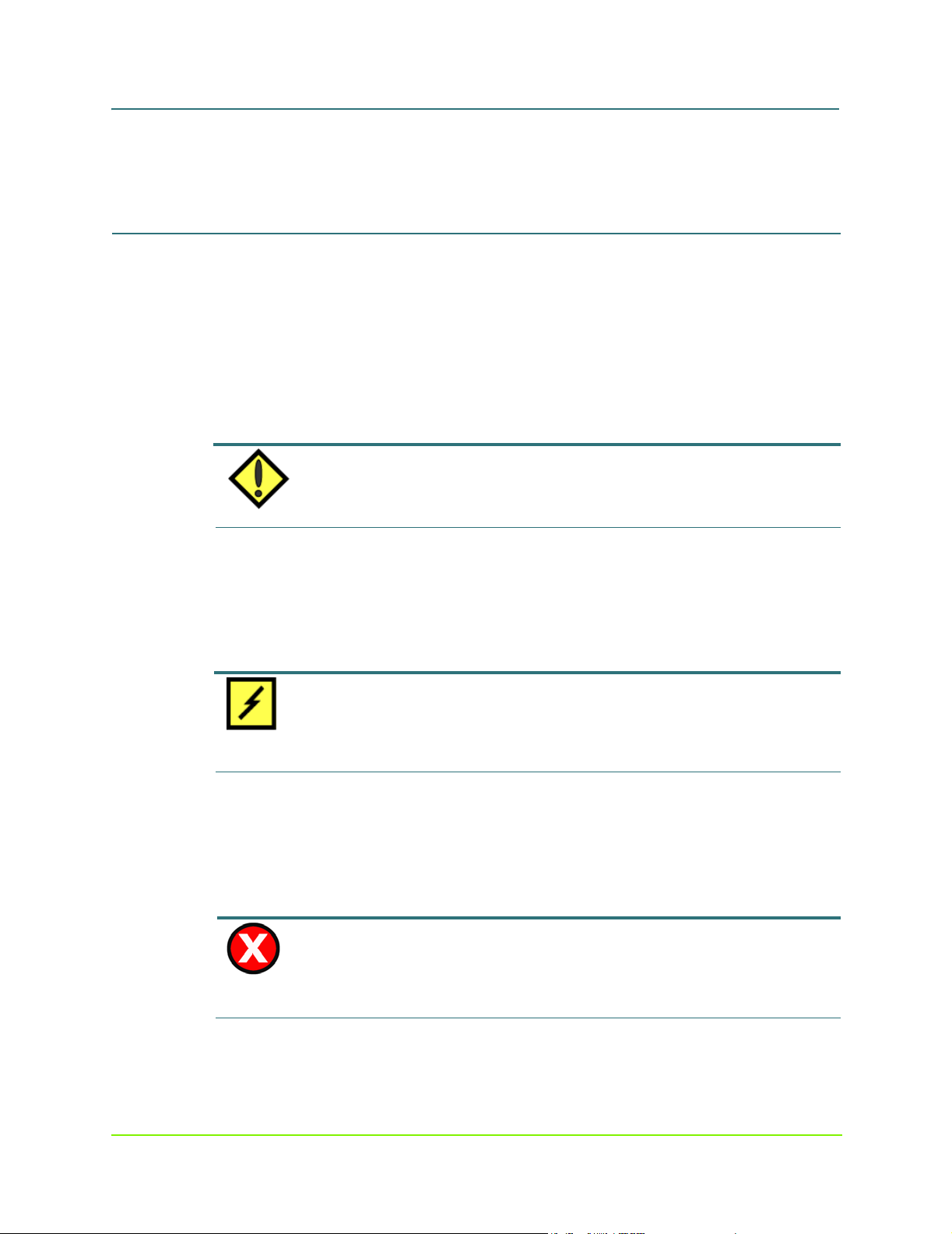
MaxAttach NAS 6000 Administration Guide
Observing Notes, Cautions, and Warnings
screen, and keyboard keys.
n Courier font identifies file names, folder names, text that either appears on the
screen or that you are required to type in, or listings of programs or output reports.
Observing Notes, Cautions, and Warnings
The following text types call out special attention to important parts of this manual. They
always appear before the actual text.
Notes
Notes provide extra information, tips, and hints regarding the topic.
NOTE
Notes provide extra information, tips, and hints regarding the topic.
Cautions
Cautions identify important information about actions that could result in damage to data
or loss of data or could cause the system to behave in unexpected ways.
Warnings
Warnings identify critical information about actions that cold result in unexpected
equipment failure, loss of critical operating system files, or potential bodily injury.
CAUTION
Cautions identify important information about actions that could result in damage to data or loss of
data or could cause the system to behave in unexpected ways.
WARNING
Warnings identify critical information about actions that cold result in unexpected equipment failure,
loss of critical operating system files, or potential bodily injury.
xx 000001628
11/07/01 -- Revision 2.0.03A

Chapter #1 - Installation - Rack
If you have a cabinet-mounted version of the MaxAttach NAS 6000, skip this section and continue
with the next chapter.
Chapter Outline
MaxAttach NAS 6000
Mounting Your NAS 6000
NOTE
This chapter provides an in depth description of installation requirements for MaxAttach
NAS 6000 rack-mountable systems. It also describes how to get your MaxAttach NAS
6000 mechanically ready by performing the following tasks:
n Install the user-supplied equipment rack.
n Install the user-supplied AC power strips.
n Install all MaxAttach equipment enclosure shelves into the rack.
n Install the MaxAttach SCSI connector cables for the hard disk drives.
n Install the MaxAttach Serial Port connector cables for the Environmental Monitoring
Unit (EMU).
n Install the Ethernet Network Interface Card (NIC) cables between the MaxAttach
NICs and your network.
n Prepare the MaxAttach for power up.
1: User-Supplied Materials and Services
The following user-supplied materials are required:
n A standard 19” equipment rack.
n The minimum rack vertical size depends on the configuration of your
MaxAttach.
Revision 2.0.03A - 11/07/01 1 000001628

MaxAttach NAS 6000 Administration Guide
n A Single Base Unit Enclosure requires four rack spaces (4U) with a size of 7”H
x 19”W x 22”D - 17.7cmH x 48.2cmW x 55.8cmD.
n A Base Unit Enclosure and one Expansion Enclosure requires 8U with a size of
14”H x 19”W x 22”D - 35.5cmH x 48.2cmW x 55.8cmD.
n A Base Unit Enclosure with two Expansion Enclosures requires 12U with a size
of 21”H x 19”W x 22”D - 53.3cmH x 48.2cmW x 55.8cmD.
n Two standard AC power strips.
n At least three power outlets per strip are required.
n More sockets per strip are recommended.
n Minimum rating for US installations is 120 VAC at 15 Amps.
n At least two network cables of sufficient length to reach from the MaxAttach to your
network.
n Two cables are required if you only want to use the card cage mounted
Ethernet Gigabit NICs.
n An additional CAT-5 cable is required if you also want to use the CPU
Motherboard Ethernet port.
n At least one network connection is required.
Chapter #1 - Installation - Rack Mounting Your NAS 6000
1: User-Supplied Materials and Services
2: Install the Equipment Rack
Follow the manufacturer’s installation recommendations for rack installation. Make sure
the unit is securely fastened to permanent fixtures such as the floor or overhead support.
3: Install the AC Power Strips
Install the AC power strips on either side of the rack. They must be close enough to the
rack for the Maxtor-supplied power cords to reach from the enclosure power supply.
4: Mount the MaxAttach NAS 6000 Equipment Enclosures
Mount the Base Unit and any equipped Expansion Units into your rack.
1. Mount the base unit enclosure shelf in the rack at the bottom of the stack and tighten
all hardware.
Chapter #1 - Installation - Rack Mounting Your NAS 6000 2 000001628
11/07/01 -- Revision 2.0.03A

MaxAttach NAS 6000 Administration Guide
Chapter #1 - Installation - Rack Mounting Your NAS 6000
1: User-Supplied Materials and Services
2. If equipped, add the first Expansion Unit enclosure above the Base Unit and tighten
all hardware.
n There should be no gap between the two enclosures.
3. If equipped, add the second Expansion Unit enclosure above the first expansion
enclosure and tighten all hardware.
n There should be no gap between the two enclosures.
5: Re-Seat All Hard Disk Drive Carrier Assemblies
Shipping vibration may have disconnected individual hard drives from their back plane
connectors. One drive at a time, pull the drive out of its Drive Bay, record its size and serial
number information, and replace it in its as-shipped Drive Bay location.
CAUTION
REPLACE DRIVE IN ORIGINAL DRIVE BAY SLOT AND SHELF: Be sure to replace the drive in its
original as-shipped Drive Bay. If you mix the drive and Drive Bays locations up, you will probably
have to reconfigure the disk RAID arrays.
1. For each drive, push down on the Ejector Tab, and then lift up on the Ejector Lever.
n The drive releases from its Drive Bay connector.
2. Pull the drive out of its Drive Bay.
n This is a good time to record the drive type and serial number.
3. Replace the drive in its Drive Bay until it begins to engage the connector.
4. Make sure the Ejector Lever is free of the Ejector Tab and place your thumbs on
either side of the drive LEDs and press gently into the bay.
5. Lower the Ejector Lever to latch the drive into place and then lock the Ejector Lever
on the Ejector Tab.
6: Review the Connector Locations
You will make connections on and between all installed enclosures The connections are for
the:
Chapter #1 - Installation - Rack Mounting Your NAS 6000 3 000001628
11/07/01 -- Revision 2.0.03A
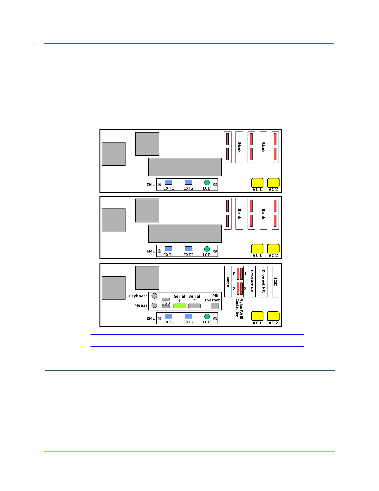
MaxAttach NAS 6000 Administration Guide
n Small Computer System Interface (SCSI) bus
n Environmental Monitoring Unit (EMU) serial port daisy chain
n NIC cables
n AC power.
Note that the base unit is on the bottom, the first expansion unit in the middle, and the
second expansion unit on the top.
Chapter #1 - Installation - Rack Mounting Your NAS 6000
1: User-Supplied Materials and Services
Figure #2 NAS 6000 Rack Mount System Back Panel Connectors
7: Install the External SCSI Cables
In this section, you will install SCSI drive cables between the Base Unit and your
Expansion Units.
Chapter #1 - Installation - Rack Mounting Your NAS 6000 4 000001628
11/07/01 -- Revision 2.0.03A
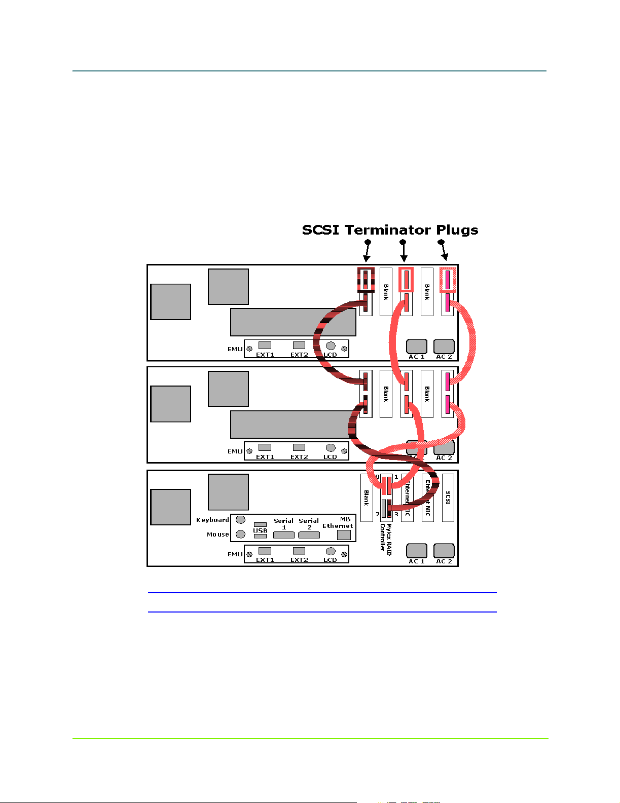
MaxAttach NAS 6000 Administration Guide
Chapter #1 - Installation - Rack Mounting Your NAS 6000
1: User-Supplied Materials and Services
Cabinet-Mount System or Single Base Unit Rack Mount System
1. Process Branch Point:
n If your system has a Base Unit and one or two Expansion Units, perform the
next step in this process immediately below in the section titled SCSI
Connections Between Base Unit and First Expansion Unit on page 5.
n If you have a cabinet-mounted stem or a single Base Unit rack-mount system,
no SCSI cabling is required. Skip ahead below to the section titled Install
EMU Cables on page 7.
Figure #3 NAS 6000 SCSI Cable Connections
SCSI Connections Between Base Unit and First Expansion Unit
2. Connect a SCSI cable from the Mylex upper left Port 0 connector to the right side
SCSI Connector Board.
3. Connect a second SCSI cable from the Mylex upper right Port 1 to the center SCSI
Chapter #1 - Installation - Rack Mounting Your NAS 6000 5 000001628
11/07/01 -- Revision 2.0.03A
MaxAttach NAS 6000 Administration Guide
Chapter #1 - Installation - Rack Mounting Your NAS 6000
1: User-Supplied Materials and Services
Connector Board.
4. Connect a third SCSI cable from the Mylex lower right Port 3 to the left side SCSI
Connector Board.
5. Process Branch Point:
n If your system only has a single Expansion Unit, your next step below is Step
#6.
n If your system has an additional Expansion Unit to install, skip below to Step
#8.
6. Add SCSI Terminator Plugs to the upper connector on each SCSI Connector Board.
7. Your SCSI Cabling is complete. Skip ahead below to section #8: - Install EMU
Cables on page 7.
SCSI Connections Between the First and Second Expansion Units
8. Connect the two left side SCSI Connector Cards with a first SCSI Cable.
n Use the lower SCSI connector for all cable runs.
9. Connect the two center SCSI Connector Cards with a second SCSI Cable.
10. Connect the two right side SCSI Connector Cards with a third SCSI Cable.
11. Add SCSI Terminator Plugs to the upper connector on each SCSI Connector Board.
NOTE
If you ordered two Expansion Units, you may end up with an extra set of unused SCSI Connector
Cards.
Chapter #1 - Installation - Rack Mounting Your NAS 6000 6 000001628
11/07/01 -- Revision 2.0.03A
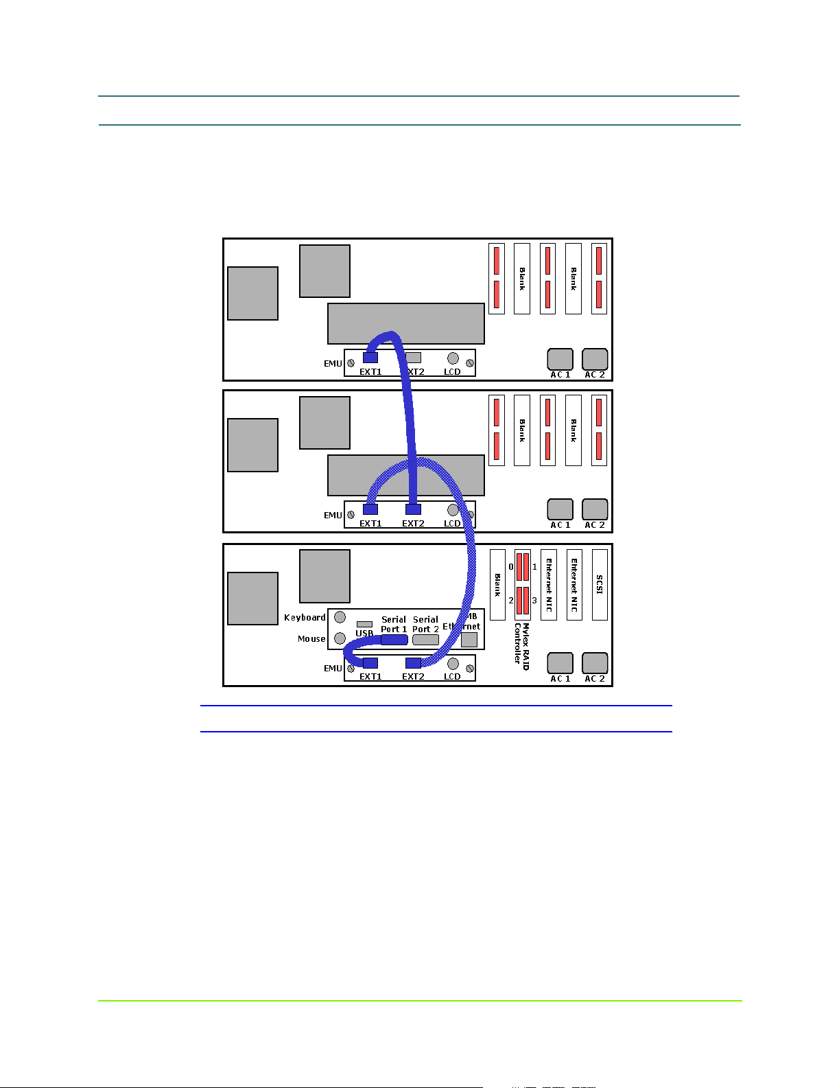
MaxAttach NAS 6000 Administration Guide
8: Install EMU Cables
In this section, you will connect the Base Unit CPU to the Environmental Monitor Unit
(EMU) mounted in each enclosure unit.
Chapter #1 - Installation - Rack Mounting Your NAS 6000
1: User-Supplied Materials and Services
Figure #4 NAS 6000 EMU Cable Connections
EMU Cable on Base Unit Installation
1. Install the Base Unit EMU Cable.
n Short Male/Male (M/M) serial cable
n Start at EMU left side EXT1 port
n Connect to CPU I/O Panel Serial Port 1.
n Connect Base Unit to First Expansion Unit
Chapter #1 - Installation - Rack Mounting Your NAS 6000 7 000001628
11/07/01 -- Revision 2.0.03A

MaxAttach NAS 6000 Administration Guide
Chapter #1 - Installation - Rack Mounting Your NAS 6000
1: User-Supplied Materials and Services
9: DECISION POINT - Are there Expansion Units to Install?
n If your system has only a single Base Unit, skip ahead to Step #13 - Install
Network and AC Power Cables on page 9 below.
n If you system has a Base Unit and one or two Expansion Units, to continue
with the step immediately below.
10: EMU Cable Between Base Unit and First Expansion Unit
1. Install the Base Unit to First Expansion Unit EMU Cable
n Longer M/F serial cable.
n Start at the Base Unit EMU EXT2 port.
n Connect to EMU EXT1 port on the first Expansion Unit.
11 : DECISION POINT - One or Two Expansion Units
n If your system has only a single Base Unit, skip ahead to Step #13 - Install
Network and AC Power Cables on page 9 below.
n If you system has a Base Unit and two Expansion Units, to continue with the
step immediately below.
12: EMU Cable Between First and Second Expansion Unit
2. Install first Expansion Unit to second Expansion Unit EMU cable.
n Longer M/F serial cable.
n Start at first Expansion Unit EMU EXT2 port.
n Connect to EMU EXT1 port on the second Expansion Unit.
3. Your EMU cabling is complete.
NOTE
There is no terminator on the last EMU EXT2 port.
Chapter #1 - Installation - Rack Mounting Your NAS 6000 8 000001628
11/07/01 -- Revision 2.0.03A

MaxAttach NAS 6000 Administration Guide
Chapter #1 - Installation - Rack Mounting Your NAS 6000
1: User-Supplied Materials and Services
13: Install Network and AC Power Cables
In this section, you will connect your Network Interface Cards (NICs) to your network
hub with user-supplied NIC cables. You will also connect the AC power cords to the
equipment shelves and connect them to user-supplied AC power strips.
Network Connections
Connect the appropriate NIC cables as follows:
1. Between each NIC and network hub or ports.
2. At least one network connection is required.
3. You can also add a network connection from the CPU I/O panel network port to
Chapter #1 - Installation - Rack Mounting Your NAS 6000 9 000001628
11/07/01 -- Revision 2.0.03A
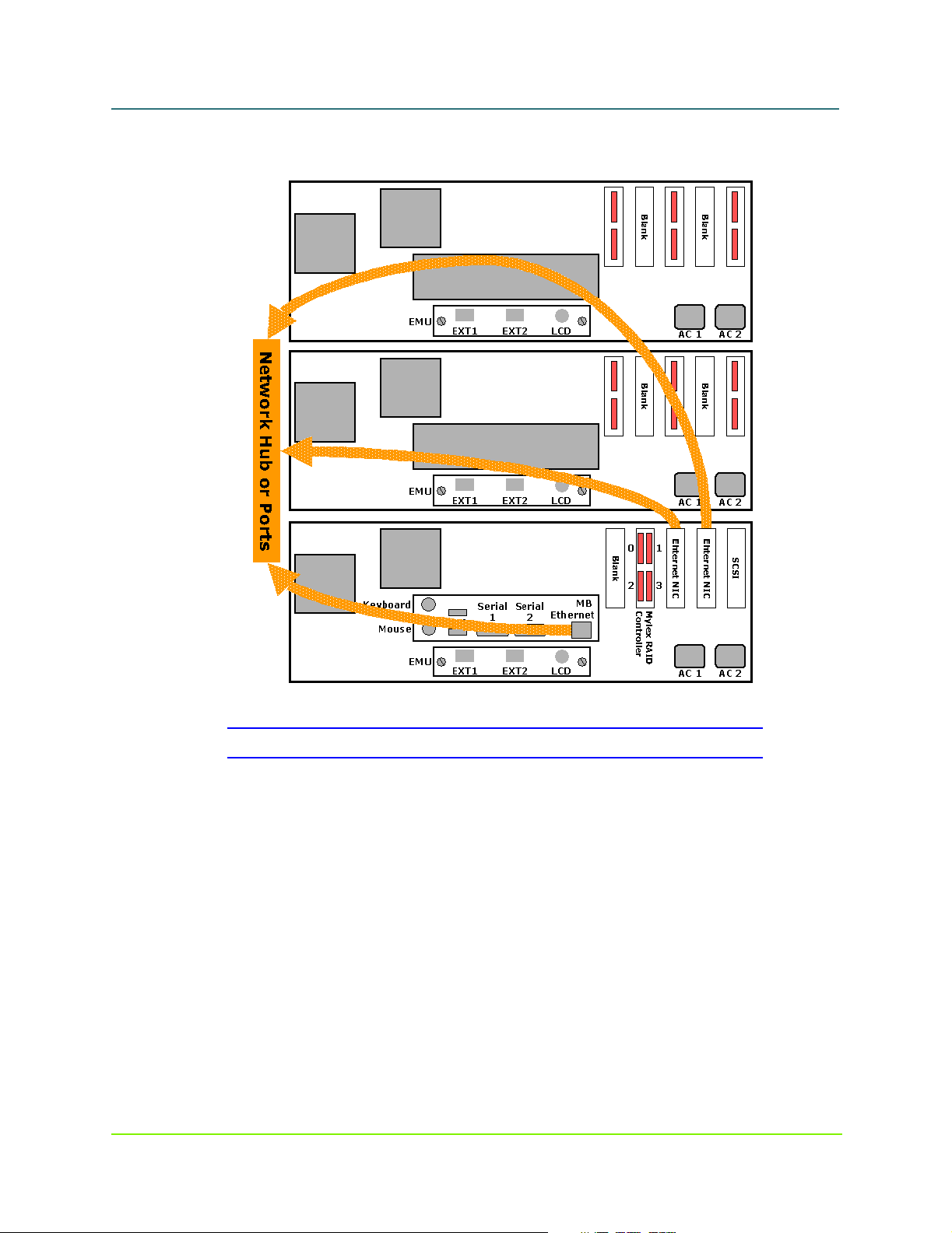
MaxAttach NAS 6000 Administration Guide
your network for administrative functions.
Chapter #1 - Installation - Rack Mounting Your NAS 6000
1: User-Supplied Materials and Services
Figure #5 NAS 6000 Network Cable Connections
Chapter #1 - Installation - Rack Mounting Your NAS 6000 10 000001628
11/07/01 -- Revision 2.0.03A

MaxAttach NAS 6000 Administration Guide
Figure #6 NAS 6000 Network Interface Card Connector Options
Chapter #1 - Installation - Rack Mounting Your NAS 6000
1: User-Supplied Materials and Services
AC Power Connections
1. Connect each AC power strip cord to the local AC power source.
n Recommend that each AC power strip be on a separate circuit.
2. Connect the NAS 6000 Expansion Unit enclosure to the user-supplied AC power
strips.
3. Install two AC power cords in each enclosure shelf.
4. Route the left side cords to the left side AC power strip.
5. Route the right side cords to the right side AC power strip.
6. Make sure all the power supply back panel ON/OFF rocker switches are in the OFF
or “O” position.
n There are two back panel switches on each enclosure shelf.
Chapter #1 - Installation - Rack Mounting Your NAS 6000 11 000001628
11/07/01 -- Revision 2.0.03A

MaxAttach NAS 6000 Administration Guide
7. Your MaxAttach NAS 6000 is ready to be powered up.
Chapter #1 - Installation - Rack Mounting Your NAS 6000
1: User-Supplied Materials and Services
Figure #7 NAS 6000 AC Power Connections
14: International AC Power Strip Solutions for Rack Mount
Systems
For MaxAttach NAS 6000 installations in locations outside of North America, localized
AC power strips are required.
Localized Internal AC Power Cords
For international locations, the MaxAttach NAS 6000 ships with the correct AC power
cord for connection between each Base and Expansion Unit equipment shelf and the
user-supplied AC power strips.
Chapter #1 - Installation - Rack Mounting Your NAS 6000 12 000001628
11/07/01 -- Revision 2.0.03A

MaxAttach NAS 6000 Administration Guide
Localized AC Power Strips/Blocks
Maxtor has identified four power strip solutions for the following countries and world
areas:
n Australia
n Europe
n Japan
n United Kingdom
n United States
The specifications of these strips plus a US approved power strip is detailed below.
Australia
Vendor:
n Panel Components Corporation
n Address: PO Box 115, Oskaloosa, IA 52577, USA
n Email: info@panelcomponents.com
n Web Site: http://www.panelcomponents.com
Chapter #1 - Installation - Rack Mounting Your NAS 6000
1: User-Supplied Materials and Services
Photo:
AC Power Strip Specifications:
n Vendor’s Part Number: 85010050
n Socket Type: AS3112
n Number of Sockets: 6
n Cord Length: 1.04 meters
n Cable Plug: AS3112
n Case: Plastic, includes circuit breaker
Chapter #1 - Installation - Rack Mounting Your NAS 6000 13 000001628
11/07/01 -- Revision 2.0.03A

MaxAttach NAS 6000 Administration Guide
n Color: White
n Rating: 250VAC / 10A
Agency Approvals:
n Australia DFT 15632
Europe
Vendor:
n Panel Components Corporation
n Address: PO Box 115, Oskaloosa, IA 52577, USA
n Email: info@panelcomponents.com
n Web Site: http://www.panelcomponents.com
Photo:
Chapter #1 - Installation - Rack Mounting Your NAS 6000
1: User-Supplied Materials and Services
AC Power Strip Specifications:
n Vendor’s Part Number: 85003040
n Socket Type: CEE 7
n Number of Sockets: 4
n Cord Length: 2.5 meters
n Cable Plug: CEE 7/7
n Case: Metal, includes rocker switch
Chapter #1 - Installation - Rack Mounting Your NAS 6000 14 000001628
11/07/01 -- Revision 2.0.03A

MaxAttach NAS 6000 Administration Guide
n Color: Orange
n Rating: 250VAC / 16A
Agency Approvals:
n Germany, VDE, 15970
Japan
Vendor:
n Wirecom Corporation
n 3PL, No. 290, Sec 4., Yen Ping North Road, Taipei, Taiwan
n Telephone: 886-2-2597-6617
n FAX: 886-2-2597-6625
n Email: Not available
n Web Site: Not available
Chapter #1 - Installation - Rack Mounting Your NAS 6000
1: User-Supplied Materials and Services
AC Power Strip Specifications:
n Vendor’s Part Number: SLW6, SP6, or CK6
n Socket Type:
n Number of Sockets: 6
n Cord Length: 0.61 meters to 7.6 meters
n Cable Plug: Mounded-on grounding type attachment plug.
n Case: Plastic
n Color: White
n Rating: 125VAC / 15A
Agency Approvals:
n UL
United Kingdom
Vendor:
n Panel Components Corporation
n Address: PO Box 115, Oskaloosa, IA 52577, USA
n Email: info@panelcomponents.com
n Web Site: http://www.panelcomponents.com
Chapter #1 - Installation - Rack Mounting Your NAS 6000 15 000001628
11/07/01 -- Revision 2.0.03A

MaxAttach NAS 6000 Administration Guide
Photo:
Chapter #1 - Installation - Rack Mounting Your NAS 6000
1: User-Supplied Materials and Services
AC Power Strip Specifications:
n Vendor’s Part Number: 85010322
n Socket Type: BS1363
n Number of Sockets: 4
n Cord Length: 2.5 meters
n Cable Plug: BA1363
n Case: Plastic, includes switch and fuse
n Color: White
n Rating: 250VAC / 13A
Agency Approvals:
n Not available from Panel Components
United States
Vendor:
n Panel Components Corporation
n Address: PO Box 115, Oskaloosa, IA 52577, USA
n Email: info@panelcomponents.com
n Web Site: http://www.panelcomponents.com
Chapter #1 - Installation - Rack Mounting Your NAS 6000 16 000001628
11/07/01 -- Revision 2.0.03A

MaxAttach NAS 6000 Administration Guide
AC Power Strip Specifications:
n Vendor’s Part Number:
n Socket Type:
n Number of Sockets:
n Cord Length:
n Cable Plug:
n Case:
n Color:
n Rating:
Agency Approvals:
n UL
Chapter #1 - Installation - Rack Mounting Your NAS 6000
1: User-Supplied Materials and Services
Chapter #1 - Installation - Rack Mounting Your NAS 6000 17 000001628
11/07/01 -- Revision 2.0.03A

MaxAttach NAS 6000 Hardware
Chapter Outline
This chapter covers the following topics:
n System features
n System data storage solutions
n Hardware features
n Advanced data protection features
n System disk drive configuration
n Enclosure configuration options
n Major components
n Base Unit Enclosure description
n Front panel description
n Back panel description
n Expansion Unit Enclosure description
n Front panel description
n Back panel description
n Description of system components
n Power supplies
n Disk drive carriers
n CPU I/O panel
n Network interface cards
n Fans and blowers
n SCSI interface connectors and cabling
n Environmental monitoring unit connectors and cabling
MaxAttach NAS 6000
Chapter #2 - Overview -
System Features
n User data capacities are stated as available disk drive array capacities when factory
configured to RAID 5 arrays across six physical disks.
Revision 2.0.03A - 11/07/01 18 000001628

MaxAttach NAS 6000 Administration Guide
n RAID 5 provides cross disk striping with distributed parity for optimal balance of
read/write speed coupled with maximum fault tolerance and recovers in the event of a
disk drive failure.
n Usable user data capacities along with relative fault tolerance and read/write speed will
vary if other RAID configuration are used.
n Enterprise NAS software powered by Windows operating system
n Cross-platform file sharing
n Hardware RAID 0, 1, 0+1, 5, and JBOD (just a bunch of disks)
n Capability to provide snapshot using Persistent Storage Manager
n Hot swappable and redundant hardware:
n Fans
n Blowers
n Power supplies
n Hard disk drive carrier assemblies.
n Up to three NIC connections:
n 10/100-BaseT Ethernet from CPU
n Gigabit Ethernet with Copper Connections
n Gigabit Ethernet with Fiber Connections
n Three mounting options:
n Standard rack-mount units for user-provided 19” rack
n Self-contained roll around 28” cabinet for under-desk installations
n Chatsworth cabinet racks in 48” and 84” heights for mounting multiple systems
in one location.
Chapter #2 - Overview - MaxAttach NAS 6000 Hardware
Overview
Overview
MaxAttach NAS 6000 is an easy to configure, enterprise-class network-attached storage
(NAS) server. This file server provides unparalleled value in data management solutions.
Based on a Microsoft Windows-Powered operating system, the MaxAttach NAS 6000
Chapter #2 - Overview - MaxAttach NAS 6000 Hardware 19 000001628
11/07/01 -- Revision 2.0.03A

MaxAttach NAS 6000 Administration Guide
provides a comprehensive suite of storage management tools or can be managed with
existing enterprise management tools. From directory support to security, to backup,
MaxAttach integrates seamlessly into any network environment.
Figure #3 MaxAttach Network Attached Storage 6000 Cabinet System
Chapter #2 - Overview - MaxAttach NAS 6000 Hardware
Enclosure Configuration Options
MaxAttach NAS 6000 is a scalable, reliable, and cost-effective storage solution for
heterogeneous file sharing, archiving and disk-based backups. Based on a Windows
Powered operating system, the MaxAttach NAS 6000 provides a comprehensive suite of
storage management tools and enables easy integration into enterprise network storage
architecture.
Cross-Platform File Sharing
MaxAttach NAS 6000 enables cross-platform file sharing among clients and servers:
Windows, UNIX/Linux, NetWare and Apple Macintosh environments. The support
extends fully into the security and directory infrastructure of these platforms, including
cross-platform file locking.
Enclosure Configuration Options
The MaxAttach NAS 6000 provides the user with highly configurable storage solutions by
varying the enclosure type, its basic capacity, and its available disk space for user data.
The MaxAttach NAS 6000 is available in two basic enclosure types of rack-mount ready in
a standard 19” rack or assembled in a roll around self-contained cabinet. The rack mount
version takes 4 rack space units (4U) per disk drive enclosure (4U, 8U or 12U).
Chapter #2 - Overview - MaxAttach NAS 6000 Hardware 20 000001628
11/07/01 -- Revision 2.0.03A

MaxAttach NAS 6000 Administration Guide
The available user storage space depends on the number of expansion enclosures that are
use with the system and the drive array selected by the user.
Rack Mount Systems
The Max Attach NAS 6000 can be mounted in a user-supplied EIA standard 19” rack for
installation in equipment rooms and wiring closets. Each equipment enclosure only
requires 4U. The base unit is mounted on the bottom, and up to two expansion enclosures
may be mounted above it.
Cabinet Mounted System
MaxAttachNAS 6000 systems may also be ordered mounted into a roll-around, lockable
cabinet for installation in office environments
n The basic cabinet system has a small footprint and measures 28.5” H x 21.75”
W x 26” D - 72.4cmH x 55.2cmW x 66cm D.
n The cabinet-mounted system can be user-lowered an extra 0.5 inches - 13mm
to accommodate under cabinet storage locations.
Chapter #2 - Overview - MaxAttach NAS 6000 Hardware
Enclosure Configuration Options
Chapter #2 - Overview - MaxAttach NAS 6000 Hardware 21 000001628
11/07/01 -- Revision 2.0.03A

MaxAttach NAS 6000 Administration Guide
Chapter #2 - Overview - MaxAttach NAS 6000 Hardware
Major Components of the Maxtor MaxAttach NAS 6000
Major Components of the Maxtor MaxAttach NAS 6000
The Base Unit and the Expansion Unit enclosures are the two major assemblies in the
MaxAttach NAS 6000. Within these two assemblies are the sub-assemblies described
below.
Figure #4 Exploded View of a Base Unit
Chapter #2 - Overview - MaxAttach NAS 6000 Hardware 22 000001628
11/07/01 -- Revision 2.0.03A

MaxAttach NAS 6000 Administration Guide
Base Unit Front Panel
The Base Unit is required for every MaxAttach NAS 6000 and contains the system CPU,
two power supplies, the fans, the necessary SCSI and Environmental Controllers, and 12
Disk Drive Carrier Assemblies. The Base Unit front panel provides local system control,
LED indicators for key system parameters, and an LCD panel for a summary of status
alerts.l
Chapter #2 - Overview - MaxAttach NAS 6000 Hardware
Major Components of the Maxtor MaxAttach NAS 6000
Figure #5 NAS 6000 Base Unit Front Panel Photo
The base unit front panel contains LED indicators for drive, power supply, and system
status and a power switch.
Figure #6 NAS 6000 Base Unit Front Panel Diagram
Chapter #2 - Overview - MaxAttach NAS 6000 Hardware 23 000001628
11/07/01 -- Revision 2.0.03A

MaxAttach NAS 6000 Administration Guide
Base Unit Front Panel Status LEDs
The figure below shows the location of the LEDs on the Base Unit front panel.
Chapter #2 - Overview - MaxAttach NAS 6000 Hardware
Overview
Overview
The MaxAttach NAS 6000 provides a wide range of alerts to inform the system
administrator about system status. There are five categories of alerts:
n LED Alerts: Front panel LEDs indicate status of disk drives, power supplies, and other
system components.
Figure #7 Base Unit Status LEDs
Figure #8 Base Unit LCD Panel
Chapter #2 - Overview - MaxAttach NAS 6000 Hardware 24 000001628
11/07/01 -- Revision 2.0.03A

MaxAttach NAS 6000 Administration Guide
n LCD Alerts: Messages are displayed on a small liquid crystal display (LCD) on the
MaxAttach front panel.
n Web UI Alerts: Error messages and condition alerts that you access from the device's
LED Status Indicators
LED (light emitting diode) status indicators are available on the front panels of the base unit
and each installed expansion unit and provide general information about:
n Activity and condition of the hard disk drive modules (on all enclosures)
n Status of the unit's power supplies (on all enclosures)
n Over-all system status (only on the Base Unit enclosure).
Chapter #2 - Overview - MaxAttach NAS 6000 Hardware
Front Panel LEDS
Figure #9 NAS 6000 LED Locations and Functions
Front Panel LEDS
There are three LED indicators in the lower right-hand corner of the main front panel that
indicate general system status. These are the System Status Alarm indicator, the Power On
indicators, and the Drive Status indicator.
n BLUE System Status Alarm Indicator - Normally OFF.
n This is a blue lamp which reports overall system status. The lamp remains off
unless there is an alarm from a source below.
n Blower or fan alarm - the blower or a fan is indicating an underspeed condition.
Chapter #2 - Overview - MaxAttach NAS 6000 Hardware 25 000001628
11/07/01 -- Revision 2.0.03A

MaxAttach NAS 6000 Administration Guide
n Power supply voltage alarm - a power supply indicates that one or more
voltages are out of limits.
n Temperature alarm - temperature inside the enclosure has exceeded
programmed limits.
n HDD alarm - one or more HDDs are failing. The failed drive will have its
Drive Status (yellow) indicator on
n GREEN Unit Power-On Indicator - Normally ON
n This is a green lamp indicating that power is on.
n The lamp will flash (indicating not ready) until the system has completed its
boot-up sequence and is ready for operation.
n YELLOW Drive Status Indicator - Normally OFF.
n This is a yellow lamp indicates there is a HDD problem.
n If there is a HDD problem this lamp will be lit.
n If any HDD module status lamp is on, this lamp will also be on.
Chapter #2 - Overview - MaxAttach NAS 6000 Hardware
Hard Disk Drive Module Status LEDs
NOTE
Expansion units indicate their own status and activity. However, you must start the base unit to
enable the expansion unit status indicators. The base unit's soft power switch controls the start-up
of the expansion units.
Hard Disk Drive Module Status LEDs
Each Hard Disk Drive (HDD) Module has two LED indicators on its front panel:
n A green Drive Activity indicator.
n This indicator flashes in response to drive accesses
n A yellow Drive Status indicator.
n This indicator is off during normal operation.
n It lights if there is an HDD module failure.
n When the unit's back panel AC power switch is on and the front-panel soft
power switch is off, all drive status indicators are on.
n As the unit powers up, the indicators go off as each drive becomes ready.
Power Supply Status LEDs
The MaxAttach 6000 is equipped with dual power supplies. Should one supply fail, the
other takes over. Each power supply has a green AC-OK indicator and a green DC-OK
indicator.
Chapter #2 - Overview - MaxAttach NAS 6000 Hardware 26 000001628
11/07/01 -- Revision 2.0.03A

MaxAttach NAS 6000 Administration Guide
n AC-OK Indicators
n These indicators remain lit as long as AC power is supplied to the power
supplies.
n If a lamp is off, it indicates that the AC power has been interrupted to the
power supply. This could indicate the supply's power cord is detached, the
power supply is turned off, the supply's circuit breaker has opened, or that there
is an open in the internal AC wiring harness.
n DC-OK Indicators
n These indicators remain lit as long as the supply's DC voltages are normal.
n If a lamp is off, it indicates either the AC power is off (check the supply's
AC-OK indicator) or one or more of the DC voltages is out of its normal
range.
NOTE
If a single DC-OK indicator is off, the system may still function properly using the other power
supply. However, you should take corrective action as soon as possible.
Chapter #2 - Overview - MaxAttach NAS 6000 Hardware
LCD Alert Panel
LCD Alert Panel
The front-panel LCD (liquid crystal display) alert panel is a small 2.25”W x 1.25”H 57mmW x 37mmH display with a resolution of 128 pixels W x 64 pixels H.
Figure #10 NAS 6000 LCD Front Panel Location and Display Areas
When the MaxAttach unit is housed in a system cabinet, each unit's alert messages can be sent to
the LCD panel on the cabinet. Up to three MaxAttach servers can be supported by the cabinet LCD
alert panel.
NOTE
Chapter #2 - Overview - MaxAttach NAS 6000 Hardware 27 000001628
11/07/01 -- Revision 2.0.03A

MaxAttach NAS 6000 Administration Guide
The LCD alert panel displays summary status messages about the state of the MaxAttach.
The display is divided into three separate status display areas:
n Logo and Alert Message Area - Top display area
n 128 W x 36H pixel area - 2.25”W x 0.7”H - 57mmW x 18mmH.
n Displays a Microsoft Windows-Powered logo during normal operation.
n It displays an alert name and title when the system generates an alert.
n Network Information Area - Middle display area
n 128W x 12H pixel area - 2.25”W x 0.26”H - 57mmW x 7mmH
n Alternately displays the unit's host name and IP address.
n Status Icon Display Area - Bottom display area
n 128W x 16H pixel area - 2.25”W x 0.3”H - 57mmW x 8mmH
n Normally displays three standard icons indicating the status of the system, disk,
and network.
n During alert conditions, the system may display multiple error condition icons.
Logo and Alert Message Display Area
Chapter #2 - Overview - MaxAttach NAS 6000 Hardware
LCD Alert Panel
The Logo and Alert Message display area is on the top of the LCD display. Under normal
operation, the logo and message display area shows a Microsoft Windows-Powered logo.
During alert conditions, the LCD panel shows an alert name and title and a message
counter that consists of the message number, a slash, and the total number of pending
messages (e.g. 1/20 for message number one of twenty total messages). If multiple messages
have been generated, the panel displays the most recent message until it is cleared at the
Web user interface.
The LCD panel reports alerts from the following systems:
Environmental Monitoring Unit (EMU)
The LCD panel displays specific information about a subsystem problem:
n Disk failure
n Power supply failure
n Fan failure
n Disk backplane voltage error
n Abnormal temperature
TCP/IP and NetBT
The LCD panel displays a network-related system problem:
n Network interface card (NIC) failure
Chapter #2 - Overview - MaxAttach NAS 6000 Hardware 28 000001628
11/07/01 -- Revision 2.0.03A

MaxAttach NAS 6000 Administration Guide
n Duplicate IP address
n Duplicate computer name (NetBT)
GAMevlog
The LCD panel displays HDD-related problems and directs users to the Web user interface
to obtain more detailed information.
Mylex RAID Controller
Mylex RAID controller-generated event are also displayed. If appropriate, the LCD panel
will also display an alert icon (described below). For example, during a Fan Failure alert,
the icon display area will show a Fan Error icon.
Figure #11 NAS 6000 Fan Failure Icon
Chapter #2 - Overview - MaxAttach NAS 6000 Hardware
LCD Alert Panel
Network Information Display Area
The Network Information display area is the middle display area on the LCD panel. Every
five seconds, the display alternates between the MaxAttach NAS 6000’s IP address and its
server name. Only the first 20 to 25 letters of the server name will be displayed; longer
names will be truncated.
Status Icon Display Area
The Status Icon Display area is the bottom display area on the LCD panel. There are 12
icons that display either transitional status such as the start-up process, normal status such as
system availability, or alert status such as disk or network problems. Multiple icons can be
displayed at the same time. During normal operation, the icon display shows a system
starting icon, a disk normal icon, and a network normal icon.
Figure #12 NAS 6000 LCD Panel Normal Operation System Icons
Chapter #2 - Overview - MaxAttach NAS 6000 Hardware 29 000001628
11/07/01 -- Revision 2.0.03A

MaxAttach NAS 6000 Administration Guide
Chapter #2 - Overview - MaxAttach NAS 6000 Hardware
The available system icons are:
Table #1 - LCD Icons and Definitions
Icon Icon Definition Icon Icon Definition
System starting (OS Starting) System normal and ready (OS Ready)
System halted (OS Halted) System shutting down (Shutdown)
Disk normal and in good condition (Disk OK) Disk error
Waiting Local area network normal and in good condition
(LAN OK)
LCD Alert Panel
Local area network error (LAN Error) Fan error, problem, or fan inoperative
Over temperature detected Voltage out of acceptable tolerance range
Chapter #2 - Overview - MaxAttach NAS 6000 Hardware 30 000001628
11/07/01 -- Revision 2.0.03A

MaxAttach NAS 6000 Administration Guide
Base Unit Back Panel
The back panel of the base unit provides I/O connection for inter-enclosure SCSI and
EMU cabling, connections for the NICs and Ethernet Port, and system hard power
switches. In addition, access to the hot swappable fans and blower is provided. Other than
on the NICs, there are no status indicators.
Chapter #2 - Overview - MaxAttach NAS 6000 Hardware
Expansion Unit
Figure #13 Base Unit Back Panel
Expansion Unit
Up to two Expansion Units may be added above a single MaxAttach NAS 6000 Base Unit.
Each Expansion Unit provides 12 disk drives mounted in their Hard Disk Driver carrier
Assemblies. In normal default RAID configuration, each unit is divided into two six-disk
RAID 5 arrays. RAID 5 is striping across multiple drives with distributed parity for an
optimum balance between fault tolerance and recovery, maximum disk drive space, and
I/O read/write speeds.
Expansion Unit Front Panel
The Expansion Enclosure front panel is similar to the Base Unit front panel with the
following exceptions:
n No System Status LED
n No Power On LED
n No Drive Status LED
n No front panel power rocker switch.
The Power Supply LEDs and the Hard Disk Drive Carrier Assembly LEDs are the same.
Chapter #2 - Overview - MaxAttach NAS 6000 Hardware 31 000001628
11/07/01 -- Revision 2.0.03A

MaxAttach NAS 6000 Administration Guide
Expansion Unit Back Panel
The Expansion Enclosure Back Panel is similar to the Base Unit with the following
exceptions:
n No CPU I/O Panel
n Three SCSI Connector Cards mounted in the card cage instead of a single RAID
Controller Card.
n No NICs
n The Power Supply Switches, Fans, and Blowers are the same.
Description of System Components
Major MaxAttach NAS 6000 Base Unit components:
n Power Supply Modules - hot swappable - two per Base Unit enclosure
n Hard Disk Drive Carrier Assemblies- hot swappable - 12 per Base Unit enclosure
n Standard network Ethernet port mounted on the CPU I/O Panel - one per Base Unit
enclosure
n High performance Gigabit Ethernet Network Interface Card (NIC) with copper
connections - one per Base Unit enclosure
n High performance Gigabit Ethernet NIC with fiber optic connections - one per Base
Unit enclosure
n Cooling Fans - hot swappable - two per Base Unit enclosure
n Cooling Blower - hot swappable - one per Base Unit enclosure
n SCSI RAID Controller Card -- connection to and management of disk arrays in the
Base Unit and any attached Expansion Units - one per Base Unit enclosure
n Environmental Monitoring Unit (EMU) Card -- monitoring system environmental
conditions such as temperature and power consumption - one per Base Unit enclosure
Chapter #2 - Overview - MaxAttach NAS 6000 Hardware
Description of System Components
Chapter #2 - Overview - MaxAttach NAS 6000 Hardware 32 000001628
11/07/01 -- Revision 2.0.03A

MaxAttach NAS 6000 Administration Guide
Power Supply Modules
There are two hot swappable power supplies per Base Unit cabinet enclosure. Each power
supply is capable of running the system independently and can be hot swapped with
another assembly at any time. Each power supply has three fans on its front panel to help
with system cooling.
Chapter #2 - Overview - MaxAttach NAS 6000 Hardware
Description of System Components
Figure #14 Hot Swappable Power Supply Three-Quarters View
Disk Drive Carriers
The system disk drives are enclosed in individual disk drive carriers 12 per enclosure.
Individual failed drives can be hot swapped while the system is running. In the default
RAID-5 configuration, a RAID-5 array will continue to function with slightly degraded
service in the event of a drive failure.
However, prompt action should be initiated to replace the failed drive. When a drive fails
in a fault tolerant RAID array, the arrays is put into a “critical” state where the failure of a
second drive in the array will lead to non-recoverable data loss. After the user replaces the
failed drive, the system administrator must initiate the RAID volume rebuild in the
background, a process which can take several hours.
Chapter #2 - Overview - MaxAttach NAS 6000 Hardware 33 000001628
11/07/01 -- Revision 2.0.03A

MaxAttach NAS 6000 Administration Guide
Optionally, an administrator can modify the default RAID configuration and leave one or
two drives available as hot spare drives. These are drives that are powered up, but unused in
any array. In the event of a drive failure, the failed drive drops offline and is replaced
automatically by the hot standby drive. The RAID rebuild process starts automatically and
immediately.
Chapter #2 - Overview - MaxAttach NAS 6000 Hardware
Description of System Components
Figure #15 Hot Swappable Hard Disk Drive Carrier Diagram and Photo
CPU I/O Panel
The CPU I/O Panel is located on the Base Unit’s Back Panel and it is the primary
diagnostic and administration interface into the MaxAttach NAS 6000.
Figure #16 CPU I/O Panel Above the EMU Connector Panel
It provides connections for:
Chapter #2 - Overview - MaxAttach NAS 6000 Hardware 34 000001628
11/07/01 -- Revision 2.0.03A

MaxAttach NAS 6000 Administration Guide
n Mouse (used only for diagnostics)
n Keyboard - used only for diagnostics
n USB ports - two - not used
n Parallel I/O port - not used
n Serial port 1 - used by the Environmental Monitoring Unit (EMU)
n Serial port 2 - not used
n Ethernet port from the CPU motherboard
CPU Ethernet Port
Every system is equipped with a standard IEEE 802.3/IEEE 802.3U-LAN-compliant
10BaseT/100BaseTX Ethernet port on the CPU motherboard of the MaxAttach NAS
6000 Base Unit chassis. Located on the CPU I/O Panel, the LAN connector for this port is
a standard RJ-45 type, compatible with standard CAT 3, 4, and 5 UTP cabling for
10BaseT operation (10 Mb/s) and Cat-5 UTP cabling for 100BaseTX operation (100
Mb/s).
Chapter #2 - Overview - MaxAttach NAS 6000 Hardware
Description of System Components
The CPU Ethernet Port is only replaceable by replacing the CPU motherboard.
Network Interface Cards (NICs)
The Maxtor MaxAttach NAS 6000 is equipped with two high performance NICs in
addition to the Ethernet port on the CPU I/O Panel. The default configured NICs are:
n A gigabit Ethernet NIC with copper wire connections
n A gigabit speed Ethernet NIC with fiber optic connections
Clients attached to a particular network type (10BaseT/100BaseTX, Gigabit copper,
Gigabit fiber-optic) access the MaxAttach NAS 6000 at the IP address assigned to each
LAN adapter.
The software drivers for Windows 2000 have been pre-installed at the factory and there is
no user configuration required other than entering local network parameters such as IP
address.
All set up operations for the installed network interfaces are automatic. Once the cables are
attached, there are no user controls or adjustments. The devices automatically detect the
network speed and configure themselves for optimum throughput.
All of the card cage NICs are field replaceable units, although system down time is required
to access the system internal components.
Chapter #2 - Overview - MaxAttach NAS 6000 Hardware 35 000001628
11/07/01 -- Revision 2.0.03A

MaxAttach NAS 6000 Administration Guide
Determining Your System's NIC Configuration
There is a five-slot card cage in the MaxAttach NAS 6000 Base Unit. The card cage holds
a video card, a RAID Controller Card, and a SCSI connector. The two remaining slots
hold the NICs. To determine which NICs are installed in your system, locate the card cage
at the back of the MaxAttach NAS 6000 and identify the three standard system cards by
their connectors (these may occupy any slot):
n The Video Card has a 15-pin DSUB connector.
n The RAID Disk Controller Card has 4 high-density 68-pin SCSI connectors.
n The SCSI Connector Card has a single 68-pin connector.
n In the remaining two card cage slots, look at the connectors and compare them to the
examples shown in the following diagram.
Chapter #2 - Overview - MaxAttach NAS 6000 Hardware
Description of System Components
Figure #17 Network Interface Cards I/O Ports Diagram
The manufacturer and configuration of the NICs may differ from your system’s
conjuration.
Hot Swappable Fans and Blower
To provide maximum system life, each chassis enclosure comes with two Back Panel fans
and a single Blower. In the event of a failure, each unit is hot swappable with no loss of
system up time.
Chapter #2 - Overview - MaxAttach NAS 6000 Hardware 36 000001628
11/07/01 -- Revision 2.0.03A

MaxAttach NAS 6000 Administration Guide
In addition, the Base Unit enclosure comes with a a fan on each CPU microprocessor.
These units are cold swappable, requiring approximately 30 minutes to access and change
out.
Chapter #2 - Overview - MaxAttach NAS 6000 Hardware
Description of System Components
Fans Blower
Figure #18 Back Panel Fan Locations
Figure #19 Fan Assembly
Chapter #2 - Overview - MaxAttach NAS 6000 Hardware 37 000001628
11/07/01 -- Revision 2.0.03A

MaxAttach NAS 6000 Administration Guide
Figure #20 Blower Assembly Diagram Three Quarter View
Chapter #2 - Overview - MaxAttach NAS 6000 Hardware
Description of System Components
CPU Fans
Figure #21 CPU Fan Location With Covers Off
Chapter #2 - Overview - MaxAttach NAS 6000 Hardware 38 000001628
11/07/01 -- Revision 2.0.03A

MaxAttach NAS 6000 Administration Guide
Chapter #2 - Overview - MaxAttach NAS 6000 Hardware
Description of System Components
SCSI Interface Connectors to Optional Expansion Enclosures
If your system has an optional expansion enclosure/s, the SCSI Interface Connectors from
the Mylex SCSI RAID controller card mounted in the PC card cage are used to
interconnect the base unit to the next expansion enclosure. There are four SCSI Ports on
the card, only Ports 0, 1, and 3 are used.
The Mylex RAID Controller Card is a field replaceable unit.
Figure #22 RAID Controller SCSI Connections Diagram and Photo - Channel 2 Not Used
Environmental Monitoring Unit (EMU) Connectors
The EMU is responsible for gathering the environmental status of the connected Base and
Expansion Units and then routing the information to the CPU O/S for action. Typical
monitoring conditions include temperature, fan rotation, and voltages that are both in and
out of specification. These environmental signals in turn generate alerts which are
distributed to some combination of LCD panel, LED indicators, email to administrators,
web user interface, and SNMP actions.
Chapter #2 - Overview - MaxAttach NAS 6000 Hardware 39 000001628
11/07/01 -- Revision 2.0.03A

MaxAttach NAS 6000 Administration Guide
The EMU is a field replaceable unit.
Figure #23 Base Unit Rear View Diagram with EMU
Chapter #2 - Overview - MaxAttach NAS 6000 Hardware
Description of System Components
Chapter #2 - Overview - MaxAttach NAS 6000 Hardware 40 000001628
11/07/01 -- Revision 2.0.03A

MaxAttach NAS 6000
Chapter #3 - Overview - Microsoft
Windows O/S Version 2.0
Chapter Outline
n Overview of operating system (O/S)
n Navigation overview
n Home and welcome screens
n Initial system setting screens
n System status screens
n Network configuration screens
n Disks and volumes screens
n Users and groups screens
n Folders and shares screens
n Maintenance screens
n Services for UNIX screens
n Services for NetWare screens
NOTE
For detailed information and instructions about using the Microsoft Windows-Powered Max
Operating System Version 2.0, consult the O/S chapters following on each topic such as Network,
Folders and Shares, and Maintenance.
Revision 2.0.03A - 11/07/01 41 000001628

MaxAttach NAS 6000 Administration Guide
O/S Overview
Navigation Overview
The navigation user interface provides both a top of screen two level navigation bar as well
as clickable hot links on every page. The figure below shows the primary navigation
settings for each top level option.
Chapter #3 - Overview - Microsoft Windows O/S Version 2.0
O/S Overview
This chapter provides you with a quick
overview of the Microsoft
Windows-Powered Max Operating
System Version 2.0, its screens, and
their major functions.
Figure #4 O/S Navigation Bar Tab Settings
Chapter #3 - Overview - Microsoft Windows O/S Version 2.0 42 000001628
11/07/01 -- Revision 2.0.03A

MaxAttach NAS 6000 Administration Guide
Welcome Page
The Welcome page is displayed when you connect to the MaxAttach NAS 6000NAS from
a client computer on the network. The navigation bars described above allow you full
access to all O/S functions.
The links on the page provide specific access to”
n Take a tour of major O/S features
n Set Administrator Password
n Set Server Appliance Name
n Set Default Page
Chapter #3 - Overview - Microsoft Windows O/S Version 2.0
Welcome Page
Tak e a Tou r
Take a Tour shows you how easy it is to use the MaxAttach NAS 6000 and provides an
overview of the O/S features and functions.
Figure #5 Welcome Page Screen
Figure #6 Take a Tour Screen
Chapter #3 - Overview - Microsoft Windows O/S Version 2.0 43 000001628
11/07/01 -- Revision 2.0.03A

MaxAttach NAS 6000 Administration Guide
Initial System Settings
Set Server Appliance Name
The Set Server Appliance Name page allows you to:
n Set the name of the server appliance
n Set the DNS suffix
n Become a member of a NT 4 or Active Directory domain or remain a member of a
workgroup.
n Set the AppleTalk name.
n Set the NetWare server name.
Chapter #3 - Overview - Microsoft Windows O/S Version 2.0
Initial System Settings
Figure #7 Set Server Appliance Name Screen
Chapter #3 - Overview - Microsoft Windows O/S Version 2.0 44 000001628
11/07/01 -- Revision 2.0.03A

MaxAttach NAS 6000 Administration Guide
Set Administrator Password
The Set Administrator Password page allows you to change the password of the MaxAttach
NAS 6000 administrator account.
Figure #8 Set Administrator Password Screen
Set Default Page
Chapter #3 - Overview - Microsoft Windows O/S Version 2.0
Initial System Settings
The Set Default Page allows you to set what page the MaxAttach NAS 6000 displays first.
You can display either the Status or Welcome page.
Figure #9 Set Default Page Screen
Chapter #3 - Overview - Microsoft Windows O/S Version 2.0 45 000001628
11/07/01 -- Revision 2.0.03A

MaxAttach NAS 6000 Administration Guide
System Status Summary
Status Page
From the Status page, you have access to real-time operational and management data for
the administration of the MaxAttach NAS 6000. The Status selection options on the
secondary menu bar provide access to specialized subsets of system status information:
n System summary
n System health
n Installed software elements
n Windows system files
n Export system information
Chapter #3 - Overview - Microsoft Windows O/S Version 2.0
System Status Summary
Figure #10 System Status Page Screen
System Summary Page
The Summary Status page provides a quick overview of system configuration information
and includes:
n Computer name
n Processor type, manufacturer, and model
n BIOS version and date
n System TCP/IP address
n Total physical memory
n Operating system and version
n Data and time for local system, install date, and last boot up date
Chapter #3 - Overview - Microsoft Windows O/S Version 2.0 46 000001628
11/07/01 -- Revision 2.0.03A

MaxAttach NAS 6000 Administration Guide
n Number of physical disks, total space, and available free space.
Figure #11 System Summary Page Screen
Chapter #3 - Overview - Microsoft Windows O/S Version 2.0
System Status Summary
System Health Page
The System Health page provides performance and health metrics for system hardware and
major subassemblies including:
n Motherboard
n Processor
n Memory
n Drives
n BIOS
n Network configuration and network adapter cards.
Figure #12 System Health Screen
Chapter #3 - Overview - Microsoft Windows O/S Version 2.0 47 000001628
11/07/01 -- Revision 2.0.03A

MaxAttach NAS 6000 Administration Guide
Installed Software Elements
The Installed Software Elements page lists all installed software modules with typically over
100 listed packages or elements. The listing provides information fields of:
n Name of the software package or element
n Version number
n State of the software:
n For normal operation, the software state is listed as Local, meaning the software
is installed on the local machine.
n Other possible software states include Absent, Error, Bad Configuration, Not
Used, or Source Absent.
n Directory location of the software package or element.
Chapter #3 - Overview - Microsoft Windows O/S Version 2.0
System Status Summary
Figure #13 Installed Software Elements Screen
Windows System Files Page
The Windows System Files page lists all the Windows DLL (dynamic linked library) files
and all of the Windows SYS (system) files. Within each type of system file, the files are
listed alphabetically by file name. Typically several hundred files are listed. The listing
provides information fields of:
n File name and DLL or SYS file extension.
n File version
n Size in bytes
n Created date
n Last modified date
n Last access date
Chapter #3 - Overview - Microsoft Windows O/S Version 2.0 48 000001628
11/07/01 -- Revision 2.0.03A

MaxAttach NAS 6000 Administration Guide
n Directory location.
Figure #14 Windows System Files Screen
Export SysInfo Page
The Export SysInfo page, allows the administrator to export either the system’s current
status or its original as-shipped status data via e-mail to the Administrator’s mailbox.
Chapter #3 - Overview - Microsoft Windows O/S Version 2.0
Network Configuration
Figure #15 Export SysInfo Screen
Network Configuration
NOTE
For detailed procedures within O/S Network Configuration, see Chapter #5 - O/S 2.0 - Network
Configuration on page 131.
Chapter #3 - Overview - Microsoft Windows O/S Version 2.0 49 000001628
11/07/01 -- Revision 2.0.03A

MaxAttach NAS 6000 Administration Guide
Network Page
The Network page allows you configure the following network-related properties of the
MaxAttach NAS 6000:
n Identification
n Global Settings
n Interfaces
n Administrator
n Administration Web Site
n SNMP Service Configuration
n Telnet
n NIC Configuration
.
Chapter #3 - Overview - Microsoft Windows O/S Version 2.0
Network Configuration
Figure #16 Network Page Screen
Identification Page
The Identification page allows you to:
n Set the name of the server appliance
n Set the DNS suffix
n Become a member of a NT 4 or Active Directory domain or remain a member of a
workgroup
n Set the AppleTalk name
Chapter #3 - Overview - Microsoft Windows O/S Version 2.0 50 000001628
11/07/01 -- Revision 2.0.03A

MaxAttach NAS 6000 Administration Guide
n Set the Netware name.
Figure #17 Server Appliance Identify Identification Page Screen
Chapter #3 - Overview - Microsoft Windows O/S Version 2.0
Network Configuration
Server Appliance Name
The server appliance name is the name of the server appliance on a network. The server
appliance name must be unique and must meet certain requirements. The new server
appliance name cannot be the same as another computer or the name of a Microsoft
Windows domain.
It is recommended that you use names that are 15 characters or fewer. The server appliance
name can be a maximum of 63 characters but should only contain the numbers 0-9, the
uppercase letters A-Z, the lowercase letters a-z, or hyphens. You may use other characters,
but doing so may prevent other users from finding your computer on the network. If your
network is using the Microsoft DNS server, you can use any characters except periods.
If other networking protocols are installed without TCP/IP, the server appliance name is
limited to 15 characters.
If you specify a server appliance name longer than 15 characters and you want longer
names to be recognized by the Microsoft Active Directory domain, the domain
administrator must enable registration of DNS names that are 16 characters or longer
DNS Suffix
Domain-name system (DNS) suffixes have the following two primary purposes:
1. When appended to the server appliance host name, DNS suffixes constitute the fully
qualified server appliance name.
Chapter #3 - Overview - Microsoft Windows O/S Version 2.0 51 000001628
11/07/01 -- Revision 2.0.03A

MaxAttach NAS 6000 Administration Guide
2. To resolve IP addresses. If your server appliance is a member of Windows NT 4
domain, a Microsoft Active Directory, or a workgroup, the DNS suffix is dependent
upon the domain environment.
Including hyphens and periods, a DNS suffix may contain up to 155 characters.
The MaxAttach NAS 6000 supports automatic DNS entry into an ADS domain. If you are
using a Windows NT 4.0 DNS server, you will need to manually enter the MaxAttach
NAS 6000 into the DNS database.
Domain
Your server appliance can be in a workgroup, active directory environment, or Windows
NT 4 domain. In Microsoft Windows NT 4 and Microsoft Active Directory
environments, a domain is a collection of computers defined by the administrator of a
network that share a common directory database.
Chapter #3 - Overview - Microsoft Windows O/S Version 2.0
Network Configuration
Utilized for Windows user and group information, Windows domains have a unique name
and provide access to the centralized user accounts and group accounts maintained by the
domain administrator. Each domain has its own security policies and security relationships
with other domains, and each domain represents a single security boundary of a Windows
computer network. Active Directory is made up of one or more domains, each of which
can span more than one physical location.
For DNS, a domain is any tree or subtree within the DNS name space. Although the
names for DNS domains often correspond to Active Directory domains, DNS domains
should not be confused with Microsoft Windows and Active Directory networking
domains.
By default a domain user must enter domain\user name when logging into a Web server
appliance or a MaxAttach NAS 6000 with a browser.
Workgroup
A workgroup is a simple grouping of computers, intended only to help users find such
things as printers and shared folders within that group. Your server appliance can be in a
workgroup, active directory environment, or Windows NT 4 domain. Workgroups in
Microsoft Windows 2000 do not offer the centralized user accounts and authentication
offered by domains.
A workgroup name must not duplicate the computer name. A workgroup name can have
as many as 15 characters, but cannot contain any of the following characters: ; : “ < > + =
\ | ? , .
Chapter #3 - Overview - Microsoft Windows O/S Version 2.0 52 000001628
11/07/01 -- Revision 2.0.03A

MaxAttach NAS 6000 Administration Guide
AppleTalk Name
By default, the AppleTalk name will be the same as the standard server name. If you change
the server name, the AppleTalk name will automatically change.
NetWare Name
The NetWare name must be different from the server appliance name. By default, the
NetWare name will be the server appliance name with _FPNW appended to it.
Global Settings Page
The Global Settings page allows you to change the overall network settings for your server
appliance by configuring the IPX settings as well as specifying the DNS suffixes and the
LMHOSTS and HOSTS file to use. These files can be used to resolve the names of any
computer or device.
Chapter #3 - Overview - Microsoft Windows O/S Version 2.0
Network Configuration
Figure #18 Global Network Settings - DNS Resolution Tab
DNS Name Resolution Tab
So that people can reach your Web site on an intranet or the Internet, you must have a
unique IP address that identifies your computer on the network. This address consists of a
long string of numbers separated by dots, for example, 172.16.255.255. Because a numeric
address is difficult for people to remember, text names, or friendly names, are used to
provide visitors with an easy-to-remember address, such as www.microsoft.com. Name
resolution involves supplying the correct numerical address from the friendly name that was
typed into a client browser.
Chapter #3 - Overview - Microsoft Windows O/S Version 2.0 53 000001628
11/07/01 -- Revision 2.0.03A

MaxAttach NAS 6000 Administration Guide
Name Resolution Systems
Windows networking components rely on the NetBIOS naming convention. In contrast,
TCP/IP components rely on a naming convention known as the Domain Name System
(DNS). Under Windows, the DNS host name of your server appliance defaults to the same
name as the NetBIOS computer name. The mapping of computer names to IP addresses
can be accomplished using one of the following two methods:
n Static
n The system administrator creates either a text file for DNS names, called a
HOSTS file, or an LMHOSTS file for NetBIOS names, and enters each
computer’s name and IP address.
n The file is then distributed on the network.
n When a request for a connection to another computer is made, the file is used
to resolve the name to the correct IP address.
n This system works well for simple networks that change infrequently.
n Dynamic
n When a client computer connects to a network with a DHCP server, the
DHCP server assigns an address and sends the IP address assignment to a
Windows Internet Name Service (WINS) server.
n The WINS server registers the computer’s name, and when a request is made
for a NetBIOS computer name, the WINS server resolves the name to the
correct IP address.
n This automatic recognition and mapping of computer names and addresses eases
the administrative burden of large or frequently changing networks.
Chapter #3 - Overview - Microsoft Windows O/S Version 2.0
Network Configuration
DNS names are typically resolved using static information. The DNS server contains a
portion of the static database listing host names and addresses. If the requested name is not
in the DNS server’s portion of the database, it sends a query to other DNS servers to get
the requested information. The DNS server that runs on Windows can be configured to
query a WINS server for name resolution of the lower levels of the DNS hierarchical
naming structure. Because WINS assigns computer names dynamically, this effectively
changes DNS from a static system to a dynamic system.
TCP/IP Hosts Tab
Windows networking components rely on the NetBIOS naming convention. In contrast,
TCP/IP components rely on a naming convention known as the Domain Name System
(DNS). Under Windows, the DNS host name defaults to the same name as the NetBIOS
computer name. The mapping of computer names to IP addresses can be accomplished
using one of the following two methods:
n Static
Chapter #3 - Overview - Microsoft Windows O/S Version 2.0 54 000001628
11/07/01 -- Revision 2.0.03A

MaxAttach NAS 6000 Administration Guide
n The system administrator creates either a text file for DNS names, called a
HOSTS file, or an LMHOSTS file for NetBIOS names, and enters each
computer's name and IP address. The file is then distributed on the network.
When a request for a connection to another computer is made, the file is used
to resolve the name with the correct IP address. This system works well for
simple networks that change infrequently.
n Dynamic
n When a client computer logs on, a DHCP server assigns an address and sends
the IP address assignment to a Windows Internet Name Service (WINS) server.
The WINS server registers the computer's name, and when a request is made
for a NetBIOS computer name, the WINS server resolves the name to the
correct IP address. This automatic recognition and mapping of computer names
and addresses eases the administrative burden of large or frequently changing
networks.
Chapter #3 - Overview - Microsoft Windows O/S Version 2.0
Network Configuration
Figure #19 Global Network Settings - TCP/IP Hosts Tab
If you are setting up multiple Web or FTP sites on a single server, each with its own IP
address, you might encounter problems with automatic DNS registration. To ensure
correct IP binding and DNS registration, disable Windows 2000 Server automatic DNS
registration and manually configure DNS registration for the Web sites. For more
information about disabling automatic DNS registration and manually configuring DNS
registration, see the Windows 2000 Server documentation.
If you want to assign multiple names to one server appliance, you must use a static name
assignment for the server appliance. On one computer you can map multiple names to one
IP address or you can use multiple names, each one mapped to its own IP address.
Chapter #3 - Overview - Microsoft Windows O/S Version 2.0 55 000001628
11/07/01 -- Revision 2.0.03A

MaxAttach NAS 6000 Administration Guide
NetBIOS LMHOSTS Tab
The use of an LMHOSTS file is optional. If an LMHOSTS file is not used, however, you
cannot use friendly text names. Instead, you must use IP addresses. This can be a
disadvantage because Web sites on the Internet usually use the DNS. If you register a
domain name for your Web site, users can contact your Web site by typing its domain
name in a browser.
Chapter #3 - Overview - Microsoft Windows O/S Version 2.0
Network Configuration
Figure #20 Global Network Settings Screen - NetBIOS LMHOSTS Tab
The LMHOSTS file is read when WINS or broadcast name resolution fails and resolved
entries are stored in a system cache for later access. When the computer uses the replication
service and does not use WINS, LMHOSTS file entries are required on import and export
servers for any computers on different subnetworks participating in the replication.
IPX Settings Tab
Internetwork Packet Exchange (IPX) is the native NetWare protocol used on many earlier
Novell networks.
To be accessible from clients running NetWare, your server appliance must provide an IPX
address.
Figure #21 Global Network Settings Screen - IPX Settings Tab
Chapter #3 - Overview - Microsoft Windows O/S Version 2.0 56 000001628
11/07/01 -- Revision 2.0.03A

MaxAttach NAS 6000 Administration Guide
Interfaces Page
The Interfaces page allows you to configure the local network settings on the MaxAttach
NAS 6000 device. From this page, you can:
n Change the name of the connection.
n Set or change the Internet Protocol (IP) and gateway addresses, subnet masks, and
metrics.
n Set or change how the server appliance resolves DNS names.
n Set or change the configuration of the Windows Internet Naming Service (WINS)
clients.
n Configure AppleTalk.
Chapter #3 - Overview - Microsoft Windows O/S Version 2.0
Network Configuration
Figure #22 Interfaces Page Screen
Interfaces Page - Rename Link
The Rename page allows you to change the name of the connection.
Figure #23 Rename Page Screen
Chapter #3 - Overview - Microsoft Windows O/S Version 2.0 57 000001628
11/07/01 -- Revision 2.0.03A

MaxAttach NAS 6000 Administration Guide
Interfaces Page - IP Link
Each computer on the network must have a unique IP address to send and receive data.
You can use the IP Address Configuration page to have your server appliance automatically
obtain the IP address configuration from the Dynamic Host Configuration Protocol
(DHCP) server. Alternately, you can configure the IP address(es) manually.
Chapter #3 - Overview - Microsoft Windows O/S Version 2.0
Network Configuration
Figure #24 IP Address Configuration Screen - General and Advanced Tabs
In addition, you can use the IP Address Configuration page to specify one or more gateway
addresses. A gateway address is the address of a local IP router residing on the same network
as the server appliance that is used to forward traffic to destinations beyond the local
network. The value in each field must be a number from 0-255.
NOTE
CHANGING IP ADDRESSES: Changing the IP address may cause the client to lose its connection
with the server appliance. To reconnect, the user must either use the new IP address or wait until
the DNS server is updated.
Chapter #3 - Overview - Microsoft Windows O/S Version 2.0 58 000001628
11/07/01 -- Revision 2.0.03A

MaxAttach NAS 6000 Administration Guide
Interfaces Page - DNS Link
The domain-name system (DNS) is a static, hierarchical name service for TCP/IP hosts.
The network administrator configures the DNS with a list of host names and IP addresses.
This allows users on the network to query the DNS to specify remote systems by host
names rather than IP addresses.
Chapter #3 - Overview - Microsoft Windows O/S Version 2.0
Network Configuration
Figure #25 DNS Servers Configuration Screen
NOTE
DNS PAGE PURPOSE: The purpose of this property page is to allow you to enter the addresses of
EXTERNAL DNS servers. The MaxAttach NAS 6000 does not contain a DNS server.
Interfaces Page - WINS Link
WINS clients attempt to register their names with a WINS server when they start or join
the network. Thereafter, WINS clients query the WINS server as needed to resolve remote
names.
WINS-enabled clients are computers that can be configured to make direct use of a WINS
server. Most WINS clients typically have more than one NetBIOS name that they must
register for use with the network. These names are used to publish various types of
network service, such as the Messenger or Workstation Service, that each computer can
use in various ways to communicate with other computers on the network. WINS-enabled
clients communicate with the WINS server to:
n Register client names in the WINS database.
n Renew client names with the WINS database.
n Release client names from the WINS database.
n Resolve names by obtaining mappings from the WINS database for user names,
Chapter #3 - Overview - Microsoft Windows O/S Version 2.0 59 000001628
11/07/01 -- Revision 2.0.03A

MaxAttach NAS 6000 Administration Guide
NetBIOS names, DNS names, and IP addresses.
Figure #26 WINS Servers Configuration Screen
Clients that are not WINS-enabled can use WINS proxies to participate in these processes
in a limited way. If you are using a DHCP server to allocate WINS server IP addresses, you
do not need to add WINS server addresses.
Chapter #3 - Overview - Microsoft Windows O/S Version 2.0
Network Configuration
Keep in mind that the Web UI only allows you to manipulate two WINS addresses, and
even then only if you statically assign the IP address for the adapter. If you have DHCP
enabled, you can remove one or two existing addresses and add different addresses, but you
will not be able to remove all WINS servers from a DHCP-enabled adapter. If you remove
two WINS addresses and do not add at least one, DHCP will automatically assign WINS
addresses.
NOTE
WINS PAGE PURPOSE: The purpose of this property page is to allow you to enter the addresses of
EXTERNAL WINS servers. The MaxAttach NAS 6000 does not contain a WINS server.
Chapter #3 - Overview - Microsoft Windows O/S Version 2.0 60 000001628
11/07/01 -- Revision 2.0.03A

MaxAttach NAS 6000 Administration Guide
Interfaces Page - AppleTalk Link
Use the AppleTalk Configuration page to specify which network adapter can receive
inbound AppleTalk connections and in which AppleTalk zone the MaxAttach will appear.
Only one AppleTalk adapter per system can be configured to receive inbound traffic.
Figure #27 AppleTalk Configuration Page
Administrator Account Page
The MaxAttach NAS 6000 server appliance comes with a set of default accounts. Only the
administrator account has administrative privileges.
Chapter #3 - Overview - Microsoft Windows O/S Version 2.0
Network Configuration
Figure #28 Administrator Account Screen
NOTE
DOMAIN ACCOUNTS AND ADMINISTRATORS: If an administrator adds a domain account to the
local administrators group, the domain user may access and administer the server appliance.
However, the administrator cannot use the Change Administrator Password page to change his
domain account password. This page can only be used to change the local administrator’s account
password.
When you change the administrator password, there is no explicit confirmation page.
However, the password is successfully changed if no error message appears after you have
submitted the change.
Chapter #3 - Overview - Microsoft Windows O/S Version 2.0 61 000001628
11/07/01 -- Revision 2.0.03A

MaxAttach NAS 6000 Administration Guide
NOTE
CHANGING THE ADMINISTRATOR PASSWORD: You cannot change the administrator password if
you are logged on as a domain user as it is outside the scope of the server appliance Web UI to
make changes to domain user accounts. Domain user accounts are stored on the domain controller,
not on the ser ver appliance.
In this context, administrator relates to the user account that is a member of the local
administrators group and is used by a current user to log on. It does not refer to the default
administrator account, called administrator.
If you receive the error message “The password cannot be changed for this
domain account
domain account
” or “The account name cannot be changed for this
” when trying to change the administrator password or account name,
you are logged on as a domain user. You must be logged on as the server appliance
administrator to change the administrator password.
Chapter #3 - Overview - Microsoft Windows O/S Version 2.0
Network Configuration
Administration Web Site Properties Page
This feature allows you to change the IP address and port that can be used to access the
administration Web site on the server appliance.
The default IP address to which the server appliance responds, or listens, is typically
changed when the server appliance is only managed on a certain subnet or a separate
management network.
The default listen ports for both encrypted and non-encrypted access can be modified as
needed to work with existing network software and configurations, for example, when no
traffic above a given port number is allowed.
Figure #29 Administration Web Server Properties
Chapter #3 - Overview - Microsoft Windows O/S Version 2.0 62 000001628
11/07/01 -- Revision 2.0.03A

MaxAttach NAS 6000 Administration Guide
SNMP Service Configuration Page
From the SNMP Service Configuration page, you can edit the values as needed on the
Agent, Traps and Security tabs. Double-click SNMP Service to access the SNMP Service
Properties page.
Chapter #3 - Overview - Microsoft Windows O/S Version 2.0
Network Configuration
Tel n e t Pa ge
The Telnet page allows you to administer your Windows-Powered server appliance from a
remote system using the Telnet protocol. You can log onto the system from a remote
Telnet client and run character-mode applications on the server appliance. The Telnet
server included with your server appliance supports a maximum of two Telnet clients at
any time, unless otherwise specified by your server appliance hardware manufacturer.
Figure #30 SNMP Service Configuration Screen
Related Topics
• See the Appendix - SNMP Management System for
detailed information about SNMP features and
functions.
Figure #31 Telnet Administration Screen
Chapter #3 - Overview - Microsoft Windows O/S Version 2.0 63 000001628
11/07/01 -- Revision 2.0.03A

MaxAttach NAS 6000 Administration Guide
NIC Configuration Page
n The Network Interface Card (NIC) adapters supplied with the MaxAttach NAS 6000
can vary, depending on which adapters were ordered and whether the system has been
upgraded.
Chapter #3 - Overview - Microsoft Windows O/S Version 2.0
Network Configuration
Figure #32 NIC Configuration Screen
In addition to the Base Unit chassis 10/100 Mb/s Ethernet adapter network port on the
CPU I/O panel, the system is equipped with two additional NICs
n a a gigabit Ethernet NIC with copper wire connections
n a gigabit speed Ethernet NIC with fiber optic connections
Chapter #3 - Overview - Microsoft Windows O/S Version 2.0 64 000001628
11/07/01 -- Revision 2.0.03A

MaxAttach NAS 6000 Administration Guide
To determine which NICs are installed in your system, locate the card cage at the back of
the MaxAttach NAS 6000 and match the connector patterns with those shown in the
diagram.
Chapter #3 - Overview - Microsoft Windows O/S Version 2.0
Network Configuration
Figure #33 Base Unit Back Panel NIC Identification
Base Unit Network Port
Every system is equipped with a standard IEEE 802.3/IEEE 802.3U-LAN-compliant
10BaseT/100BaseTX Ethernet port. It is supplied on the CPU I/O Panel of the Maxtor
MaxAttach NAS 6000 Base Unit chassis.
The LAN connector for this port is a standard RJ-45 type, compatible with standard CAT
3, 4, and 5 UTP cabling for 10BaseT operation (10 Mb/s) and Cat-5 UTP cabling for
100BaseTX operation (100 Mb/s).
Standard NIC Configuration
The software drivers for each NIC have been pre-installed at the factory. There is no user
configuration required other than entering local area network parameters (IP address, server
name, domain and workgroup, etc.).
Every installed NIC should be connected to a separate subnet and be assigned a unique IP
address. The architecture of the network permitting, clients can access the MaxAttach with
any of its IP addresses.
Chapter #3 - Overview - Microsoft Windows O/S Version 2.0 65 000001628
11/07/01 -- Revision 2.0.03A

MaxAttach NAS 6000 Administration Guide
All NICs are initially configured as DHCP clients at the factory so that they will get their
IP addresses and other network parameters from a DHCP server. If there is no DHCP
server on your network, the administrator must assign fixed network parameters to each
NIC.
When you start the Maxtor MaxAttach NAS 6000 for the first time and it does not find a
DHCP server, it assigns itself a temporary IP address (169.254.nn.mm, where nn and mm are
random integers in the range of 0 - 255). Use MaxNeighborhood Discovery and Setup
Wizard to discover the MaxAttach NAS 6000's temporary IP address, then use Internet
Explorer running on a client computer to access the Maxtor MaxAttach NAS 6000 at its
temporary IP address and follow the steps of the O/S First Time Setup Wizard to set the
required network parameters.
NOTE
Initially, connect only one MaxAttach NIC to the network. MaxNeighborhood should be run on a
client computer attached to the same network subnet, since it may not see a MaxAttach (with IP
169.254.nn.mm) across a network router or switch.
Chapter #3 - Overview - Microsoft Windows O/S Version 2.0
Network Configuration
All other setup operations for the installed network interfaces are automatic. There are no
other user controls or adjustments. The devices automatically detect the network speed and
configure themselves for optimum throughput.
Chapter #3 - Overview - Microsoft Windows O/S Version 2.0 66 000001628
11/07/01 -- Revision 2.0.03A

MaxAttach NAS 6000 Administration Guide
Chapter #3 - Overview - Microsoft Windows O/S Version 2.0
Gigabit Ethernet NIC with Copper Connections
The gigabit network interface card is a full-duplex gigabit Ethernet interface that is fully
compliant with IEEE 802.3z for UTP and fully compliant with IEEE 802.3ab and IEEE
802.3u. The interface is compatible with all 10/100/1000BaseT hubs, switches and routers.
It can provide sustained throughput of up to 1 Gb/s.
LED #A is ON when the adapter is at 10 Mbits/second.
LED #B is ON when set to 100 Mbits/second.
LED #C is ON when set to 1000 Mbits/second.
LED steady ON for an established valid network link.
LED slow blinking during transmit or receive network activity.
Network Configuration
Figure #34 Gigabit NIC with Copper Connections Status LEDs
The gigabit Ethernet NIC has an RJ-45 connector for connection of Category 5 or 5E
copper cabling. The maximum cable length is 100 meters or 328 feet.
There are three LEDs on the gigabit NIC connector plate, one for each port speed option:
10 Mbps (Ethernet), 100 Mbps (Fast Ethernet), and 1000 Mbps (Gigabit Ethernet).
n The A LED is ON when the adapter is at 10 Mb/s.
n The B LED is ON when the adapter is at 100 Mb/s.
n The C LED is ON when the adapter is at 1000 Mb/s.
n A LED is ON when there is a valid network link established.
n A LED flashes slowly during network activity (transmit or receive).
The required software drivers have been pre-installed at the factory and there is no user
configuration required.
Gigabit Ethernet NIC with Fiber Optic Connections
The gigabit Ethernet NIC with fiber optic connections connects the MaxAttach NAS 6000
to a gigabit Ethernet network via a standard fiber interface. It is fully interoperable with
existing Ethernet equipment and operates at 1 gigabit per second (Gb/s) in full-duplex
mode when connected to a gigabit Ethernet port.
Chapter #3 - Overview - Microsoft Windows O/S Version 2.0 67 000001628
11/07/01 -- Revision 2.0.03A

MaxAttach NAS 6000 Administration Guide
The NIC supports standard Ethernet minimum and maximum frame sizes (64 to 1518
bytes), frame format, and IEEE 802.2 LLC specifications. The underlying NIC technology
ensures high performance and maximum bandwidth availability to prevent server
congestion and complies with the IEEE 802.3z full-duplex gigabit Ethernet fiber interface
standard and with the IEEE 802.3x frame-based flow control standard.
Two status LEDs are located above the cable connector on the
MaxAttach NAS 6000 back panel. They indicate the link status as
follows:
Data LED
- ON or FLASHING: NIC is detecting network data. The frequency of
the flashes varies with the amount of network traffic.
- OFF: No connection between the NIC and the switch.
Link LED
- ON: Connection between the NIC and the switch is established.
- FLASHING: Software has disabled the port.
Chapter #3 - Overview - Microsoft Windows O/S Version 2.0
Network Configuration
The gigabit Ethernet NIC with fiber optic connections connects to the network via
standard SC/MMF cabling. Compliant cabling types and maximum transmission distances
are shown in the table below.:
Signal Type
1000BASE-SX
Short wavelength
(850 nm)
Two status LEDs are located above the cable connector on the MaxAttach NAS 6000 back
panel. They indicate the link status as follows:
n Data LED
Figure #35 Gigabit Ethernet NIC with Fiber Optic Connections Status LEDs
Table #1 - Cabling Types and Distances
Connecto
r
Typ e
Cable
Typ e
Cable
Diameter
(Microns)
Modal
Bandwidth
(MHz*km)
SC MMF 62.5 160 722 (220)
SC MMF 62.5 200 902 (275)
50 400 1641 (500)
50 500 1805 (550)
Maximum
Length
Feet (Meters)
Chapter #3 - Overview - Microsoft Windows O/S Version 2.0 68 000001628
11/07/01 -- Revision 2.0.03A

MaxAttach NAS 6000 Administration Guide
n On or flashing: NIC is detecting network data. The frequency of the flashes
varies with the amount of network traffic.
n Off: No connection between the NIC and the switch.
n Link LED
n On: Connection between the NIC and the switch is established.
n Flashing: Software has disabled the port.
n Off: No connection between the NIC and switch.
The required software drivers have been pre-installed at the factory and there is no user
configuration required.
Chapter #3 - Overview - Microsoft Windows O/S Version 2.0
Network Configuration
Chapter #3 - Overview - Microsoft Windows O/S Version 2.0 69 000001628
11/07/01 -- Revision 2.0.03A

MaxAttach NAS 6000 Administration Guide
Disks and Volumes
NOTE
For detailed procedures within O/S Disks and Volumes Configuration, see Chapter #6 - O/S 2.0 Disk and Volume Properties on page 168.
Disks Page
From the Disks page, you can:
n Configure the properties of individual disks and volumes residing on the MaxAttach
NAS 6000.
n Configure disk quotas for volumes on the MaxAttach NAS 6000.
n Use Persistent Storage Manager to take point-in-time snapshots of selected volumes.
n Defragment the disks
n Configure the disk array using the Mylex GAM software.
Chapter #3 - Overview - Microsoft Windows O/S Version 2.0
Disks and Volumes
Figure #36 Disks Page Screen
Chapter #3 - Overview - Microsoft Windows O/S Version 2.0 70 000001628
11/07/01 -- Revision 2.0.03A

MaxAttach NAS 6000 Administration Guide
Disks and Volumes
From the Disks and Volumes page, you can choose to configure the disks or volumes on
the server appliance. To manage disks and volumes on the server appliance you need to log
on to Terminal Services Advanced Client.
Chapter #3 - Overview - Microsoft Windows O/S Version 2.0
Disks and Volumes
Figure #37 Disks and Volumes Page Screen
Terminal Services Advanced Client
Terminal Services Advanced Client is a general purpose tool that gives you full access to
your server appliance. When accessed using the Disks and Volumes page, the Terminal
Services Advanced Client assumes a dedicated mode and can only be used to manage disks
and volumes on your server appliance.
Terminal Services Advanced Client supports only two concurrent connections.
Additionally, if you navigate to another page during an open session, the client will be
disconnected but the session will be preserved.
Disk Quotas Page
Disk quotas track and control disk space use in volumes. You can configure the volumes on
your server appliance to perform the following tasks:
n Prevent further disk space use and log an event when a user exceeds a specified disk
space limit.
Chapter #3 - Overview - Microsoft Windows O/S Version 2.0 71 000001628
11/07/01 -- Revision 2.0.03A

MaxAttach NAS 6000 Administration Guide
n Log an event when a user exceeds a specified disk space warning level.
Figure #38 Disk Volumes and Quotas Page Screen
Disk Quota Page - Quota Link
Chapter #3 - Overview - Microsoft Windows O/S Version 2.0
Disks and Volumes
When you enable disk quotas, you can set both the disk quota limit and the disk quota
warning level. The disk quota limit specifies the amount of disk space a user is allowed to
use. The warning level specifies the point at which a user is nearing his or her quota limit.
For example, you can set a user’s disk quota limit to 50 megabytes (MB), and the disk
quota warning level to 45 MB. In this case, the user can store no more than 50 MB on the
volume. If the user stores more than 45 MB on the volume, you can have the disk quota
system log a system event.
Figure #39 Default Quota Page Screen
Chapter #3 - Overview - Microsoft Windows O/S Version 2.0 72 000001628
11/07/01 -- Revision 2.0.03A

MaxAttach NAS 6000 Administration Guide
In addition, you also can specify that users can exceed their quota limit. Enabling quotas
and not limiting disk space use is useful when you do not want to deny users access to a
volume, but want to track disk space use on a per-user basis. You can also specify whether
or not to log an event when users exceed either their quota warning level or their quota
limit.
When you enable disk quotas for a volume, volume usage is automatically tracked from
that point forward, but existing volume users have no disk quotas applied to them. You can
apply disk quotas to existing volume users by adding new quota entries on the Quota
Entries page.
Disk Quotas Page - Quota Entries
When you enable disk quotas on a volume, every user’s disk volume usage is monitored
and treated differently depending on the quota management settings for the specific user.
For example, users who have write access to the volume and who have not exceeded their
quota limit can store data on the volume. The first time a user writes data to a
quota-enabled volume, default values for the disk space limit and the warning level are
automatically assigned by the quota system.
Chapter #3 - Overview - Microsoft Windows O/S Version 2.0
Disks and Volumes
Figure #40 Quota Entries Page Screen
The Quota Entries page allows you to add, delete, or configure disk quotas for any server
appliance user. Quotas are managed using the Object/Task Selector, which has the
following columns:
n Logon Name - This column displays the logon name of each user with registered access
to the server appliance.
n Status - This column indicates whether or not the user has exceeded the assigned quota
limit.
n Amount Used - This column indicates the amount of disk space currently being used
Chapter #3 - Overview - Microsoft Windows O/S Version 2.0 73 000001628
11/07/01 -- Revision 2.0.03A

MaxAttach NAS 6000 Administration Guide
by a given user.
n Quota Limit - This column indicates the maximum amount of disk space that a user
can occupy on a volume.
n How the server appliance behaves when the quota limit is exceeded depends on
the settings on the Quota property page, accessible through the Disk Quota tab.
n If the Deny disk space to users exceeding quota limit check box is selected, the
user will not be able to exceed this limit.
n If the Log event when a user exceeds their quota limit check box is selected, an
event log message will be logged.
n If neither option is selected, no action is taken.
n Warning Level - This column indicates the maximum amount of disk space that a
particular user can use before a warning appears indicating that the quota has nearly
been reached.
NOTE
Chapter #3 - Overview - Microsoft Windows O/S Version 2.0
Disks and Volumes
QUOTA LIMIT WARNING: A warning will only be generated if the user exceeds the warning limit
specified on the Quota Entries page, and if a Log event is selected on the Default Quota page. If the
Log event check box is not selected, no warning will be generated and this column will remain
empty. Typically the Warning Limit value is set slightly fewer than the Quota Limit value.
Persistent Storage Manage Page
Persistent Storage Manager allows you to create snapshot images of volumes on the server
appliance. These snapshots, called persistent images, preserve data on selected volumes in
case of a system or power failure. Each persistent image is saved as a volume on the file
system to allow clients read-only or read/write permission. You can create a persistent
image immediately through this configuration system or schedule it as a one-time or
recurring event.
The Persistent Storage Manager page allows you to:
n Set the global parameters
n Configure each volume
n Create one-time or recurring persistent image schedules of scheduled volumes
n Create or view persistent images and their properties
Chapter #3 - Overview - Microsoft Windows O/S Version 2.0 74 000001628
11/07/01 -- Revision 2.0.03A

MaxAttach NAS 6000 Administration Guide
n Use existing persistent images to recover data
Figure #41 Persistent Storage Manager Home Page Screen
Once created, a persistent image of a volume appears as a directory on the original volume.
The image inherits permission rights from the original volume. Images are used the same as
conventional system volumes. However, unlike conventional volumes, persistent images
can be restored to the precise content of the original volume at the time the snapshot was
created.
Chapter #3 - Overview - Microsoft Windows O/S Version 2.0
Disks and Volumes
Persistent Storage Manager is fully integrated with Microsoft Windows Scheduler, allowing
complete unattended management of persistent image creation and rotation on a periodic
basis.
Use Persistent Storage Manager to control system resource usage, optimization, and
Persistent image management.
Persistent Storage Manager Global Settings Page
The Global Settings page allows you to modify overall settings for the Persistent Storage
Manager. Some options will be disabled if there are already active persistent images. The
Restore Defaults button will reset the system defaults.
Figure #42 Persistent Storage Manager Image Global Settings Page Screen
You can view or change the following global settings:
Chapter #3 - Overview - Microsoft Windows O/S Version 2.0 75 000001628
11/07/01 -- Revision 2.0.03A

MaxAttach NAS 6000 Administration Guide
Maximum Persistent Images
Specifies the maximum number of active persistent images the server will support to a
maximum of 250. If adding another persistent image would exceed this number, the system
will delete the oldest existing persistent image.
Specifies the amount of time a volume must be dormant before a persistent image is
created. Prior to starting a persistent image, the system will wait for the volume to be
imaged to become inactive. The default value will allow systems to start an image with a
consistent file set and a minimal time-out. Administrators can change this value for system
optimization. Reducing the inactive period will allow you to create persistent images even
on busy systems, but with possible synchronization problems within applications which are
concurrently writing to multiple files.
Chapter #3 - Overview - Microsoft Windows O/S Version 2.0
Disks and Volumes
Inactive Period
Inactive Time Out
Specifies how long the server should try to create a persistent image. A persistent image will
not begin until a period of relative inactivity set by the Inactive period has passed. If an
interval passes that is longer than the Inactive timeout period, the persistent image will not
be created and a notice generated to the system event log.
Image Directory
Specifies the root directory used for the persistent image. Each persistent image appears as a
subdirectory of the volume that is being imaged. The entire content of the volume as it
existed at the moment the persistent image was created will appear under this directory.
Chapter #3 - Overview - Microsoft Windows O/S Version 2.0 76 000001628
11/07/01 -- Revision 2.0.03A

MaxAttach NAS 6000 Administration Guide
Persistent Storage Manager Volume Settings Page
The Volume Settings page allows you to view the Persistent Storage Manager attributes for
each volume and change the volume settings using the Tasks list.
Chapter #3 - Overview - Microsoft Windows O/S Version 2.0
Disks and Volumes
Figure #43 Persistent Storage Management Volume Configuration Screens
This page displays the following information:
n Available Volume - Lists each volume that can support persistent images. You can
select the volume you want to configure.
n Size - Displays the size of the volume.
n Free Space - Displays the available storage size of the volume.
n Cache Size - Specifies the amount of space allocated to the cache file. Increasing this
value will allow more and larger persistent images to be maintained.
n Usage - Displays the current cache file use as a percentage of the Cache Size.
Persistent Storage Management Configure Volume Settings Page
The Configure Volume Settings page, allows you to modify the various aspects of the
Persistent Storage Manager volume attributes. Some of the fields will appear read-only if
there are active persistent images. The Restore Defaults button will re-establish the system
defaults.
You can view or change the following settings:
n Warning threshold reached when - Defines the percentage of cache space which, when
consumed, will trigger warning messages to the system event log.
Chapter #3 - Overview - Microsoft Windows O/S Version 2.0 77 000001628
11/07/01 -- Revision 2.0.03A

MaxAttach NAS 6000 Administration Guide
n Begin deleting images when - Defines the percentage of cache space which, when
consumed, will trigger the automatic deletion of the oldest persistent image on the
system. Automatic persistent image deletions are recorded in the system log.
n Cache size - Specifies the amount of space allocated to the cache file. Increasing this
value will allow more and larger persistent images to be maintained. Make sure that
adequate space is available on the drive where persistent images are stored.
Persistent Storage Management Schedules Page
The Schedules page displays a list of scheduled persistent images and associated tasks.
Each scheduled persistent image contains information such as its scheduled time, day,
frequency, starting date, and group name.
The Schedules page allows you to create new schedules, delete existing schedules, and edit
schedule properties.
Chapter #3 - Overview - Microsoft Windows O/S Version 2.0
Disks and Volumes
Figure #44 Persistent Storage Manager Image Schedule Screens
Create Schedule
To create a new schedule, you must supply a starting time, repeat period, starting day,
volume, and the number of persistent images to make available to users.
Chapter #3 - Overview - Microsoft Windows O/S Version 2.0 78 000001628
11/07/01 -- Revision 2.0.03A

MaxAttach NAS 6000 Administration Guide
Persistent Images Page
The Persistent Images page allows you to create, delete, edit properties and undo changes
made to the persistent image.
Figure #45 Persistent Storage Manager Images Page Screen
The page displays the following information:
n Time Stamp - Displays date and time the image was created.
n Image Name - Displays the name of the image.
n Attributes - Displays the read-only or read/write attribute of the image.
n Weight - Displays the relative retention weight of the image.
n Volumes - Displays the volume that was imaged.
Chapter #3 - Overview - Microsoft Windows O/S Version 2.0
Disks and Volumes
Restore Persistent Images
The Persistent Images to Restore page displays a list of all persistent images. You can
choose to view an image or restore your server appliance to an image you have previous
created.
Figure #46 Persistent Storage Manager Restore Images Page Screen
Chapter #3 - Overview - Microsoft Windows O/S Version 2.0 79 000001628
11/07/01 -- Revision 2.0.03A

MaxAttach NAS 6000 Administration Guide
Disk Defragmenter Page
The Disk Defragmenter allows access to the native Windows 2000 disk defragmenter
through the Web UI. Select the disk you want to defragment and click Defragment.
Chapter #3 - Overview - Microsoft Windows O/S Version 2.0
Disks and Volumes
Figure #47 Disk Defragmenter
Chapter #3 - Overview - Microsoft Windows O/S Version 2.0 80 000001628
11/07/01 -- Revision 2.0.03A
 Loading...