

Seagate ST336754SS - Cheetah 36.7 GB Hard Drive, Cheetah 15K.4 SAS, ST373454SS Product Manual
Page 1
Cheetah 15K.4 SAS
ST3146854SS
ST373454SS
ST336754SS
Page 2

Page 3
Cheetah 15K.4 SAS
ST3146854SS
ST373454SS
ST336754SS
Page 4

©2004, 2005 Seagate Technology LLC All rights reserved
Publication number: 100350601, Rev. B
May 2005
Seagate and Seagate Technology are registered tradem arks of Seagate Technology LLC.
Cheetah, SeaTools, SeaF ONE, SeaBOARD, Sea TDD, and the Wave logo are eith er regis
tered trademarks or trademarks of Seagate T echnology LLC. Other product names are registered trademarks or trademarks of their owners.
Seagate reserves the right to ch ange, witho ut notice, product offerings or spec ifications . No
part of this publication may be reproduc ed in any form w ithout wr itte n per mi ssio n of Seagate
Technology LLC.
-
Page 5

Revision status summary sheet
Revision Date Sheets Affected
Rev. A 11/22/04 All.
Rev. B 05/04/05 Pages 11, 37, 58, and 59.
Page 6

Page 7

Contents
1.0 Scope. . . . . . . . . . . . . . . . . . . . . . . . . . . . . . . . . . . . . . . . . . . . . . . . . . . . . . . . . . . . . . . . . . . . . . . . 1
2.0 Standards, compliance and reference documents . . . . . . . . . . . . . . . . . . . . . . . . . . . . . . . . . . . 3
2.1 Standards . . . . . . . . . . . . . . . . . . . . . . . . . . . . . . . . . . . . . . . . . . . . . . . . . . . . . . . . . . . . . . 3
2.1.1 Electromagnetic compatibility. . . . . . . . . . . . . . . . . . . . . . . . . . . . . . . . . . . . . . . . 3
2.2 Compliance . . . . . . . . . . . . . . . . . . . . . . . . . . . . . . . . . . . . . . . . . . . . . . . . . . . . . . . . . . . . . 4
2.2.1 Electromagnetic compliance . . . . . . . . . . . . . . . . . . . . . . . . . . . . . . . . . . . . . . . . 4
2.3 Reference documents . . . . . . . . . . . . . . . . . . . . . . . . . . . . . . . . . . . . . . . . . . . . . . . . . . . . . 5
3.0 General description . . . . . . . . . . . . . . . . . . . . . . . . . . . . . . . . . . . . . . . . . . . . . . . . . . . . . . . . . . . . 7
3.1 Standard features . . . . . . . . . . . . . . . . . . . . . . . . . . . . . . . . . . . . . . . . . . . . . . . . . . . . . . . . 8
3.2 Media description . . . . . . . . . . . . . . . . . . . . . . . . . . . . . . . . . . . . . . . . . . . . . . . . . . . . . . . . 8
3.3 Performance . . . . . . . . . . . . . . . . . . . . . . . . . . . . . . . . . . . . . . . . . . . . . . . . . . . . . . . . . . . . 8
3.4 Reliability . . . . . . . . . . . . . . . . . . . . . . . . . . . . . . . . . . . . . . . . . . . . . . . . . . . . . . . . . . . . . . . 9
3.5 Formatted capacities . . . . . . . . . . . . . . . . . . . . . . . . . . . . . . . . . . . . . . . . . . . . . . . . . . . . . . 9
3.6 Programmable drive capacity . . . . . . . . . . . . . . . . . . . . . . . . . . . . . . . . . . . . . . . . . . . . . . . 9
3.7 Factory-installed accessories . . . . . . . . . . . . . . . . . . . . . . . . . . . . . . . . . . . . . . . . . . . . . . . 9
3.8 Factory-installed options . . . . . . . . . . . . . . . . . . . . . . . . . . . . . . . . . . . . . . . . . . . . . . . . . . 10
3.9 User-installed accessories. . . . . . . . . . . . . . . . . . . . . . . . . . . . . . . . . . . . . . . . . . . . . . . . . 10
4.0 Performance characteristics . . . . . . . . . . . . . . . . . . . . . . . . . . . . . . . . . . . . . . . . . . . . . . . . . . . . 11
4.1 Internal drive characteristics . . . . . . . . . . . . . . . . . . . . . . . . . . . . . . . . . . . . . . . . . . . . . . . 11
4.2 Seek performance characteristics . . . . . . . . . . . . . . . . . . . . . . . . . . . . . . . . . . . . . . . . . . . 11
4.2.1 Access time . . . . . . . . . . . . . . . . . . . . . . . . . . . . . . . . . . . . . . . . . . . . . . . . . . . . 11
4.2.2 Format command execution time (minutes) . . . . . . . . . . . . . . . . . . . . . . . . . . . 12
4.2.3 General performance characteristics. . . . . . . . . . . . . . . . . . . . . . . . . . . . . . . . . 12
4.3 Start/stop time . . . . . . . . . . . . . . . . . . . . . . . . . . . . . . . . . . . . . . . . . . . . . . . . . . . . . . . . . . 12
4.4 Prefetch/multi-segmented cache control . . . . . . . . . . . . . . . . . . . . . . . . . . . . . . . . . . . . . . 13
4.5 Cache operation . . . . . . . . . . . . . . . . . . . . . . . . . . . . . . . . . . . . . . . . . . . . . . . . . . . . . . . . 13
4.5.1 Caching write data . . . . . . . . . . . . . . . . . . . . . . . . . . . . . . . . . . . . . . . . . . . . . . . 14
4.5.2 Prefetch operation . . . . . . . . . . . . . . . . . . . . . . . . . . . . . . . . . . . . . . . . . . . . . . . 14
4.5.3 Optimizing cache performance for desktop and server applications . . . . . . . . . 15
5.0 Reliability specifications . . . . . . . . . . . . . . . . . . . . . . . . . . . . . . . . . . . . . . . . . . . . . . . . . . . . . . . 17
5.1 Error rates . . . . . . . . . . . . . . . . . . . . . . . . . . . . . . . . . . . . . . . . . . . . . . . . . . . . . . . . . . . . . 17
5.1.1 Recoverable Errors . . . . . . . . . . . . . . . . . . . . . . . . . . . . . . . . . . . . . . . . . . . . . . 17
5.1.2 Unrecoverable Errors. . . . . . . . . . . . . . . . . . . . . . . . . . . . . . . . . . . . . . . . . . . . . 17
5.1.3 Seek errors. . . . . . . . . . . . . . . . . . . . . . . . . . . . . . . . . . . . . . . . . . . . . . . . . . . . . 18
5.1.4 Interface errors. . . . . . . . . . . . . . . . . . . . . . . . . . . . . . . . . . . . . . . . . . . . . . . . . . 18
5.2 Reliability and service . . . . . . . . . . . . . . . . . . . . . . . . . . . . . . . . . . . . . . . . . . . . . . . . . . . . 18
5.2.1 Annualized Failure Rate (AFR) . . . . . . . . . . . . . . . . . . . . . . . . . . . . . . . . . . . . . 18
5.2.2 Preventive maintenance. . . . . . . . . . . . . . . . . . . . . . . . . . . . . . . . . . . . . . . . . . . 18
5.2.3 Hot plugging the drive . . . . . . . . . . . . . . . . . . . . . . . . . . . . . . . . . . . . . . . . . . . . 18
5.2.4 S.M.A.R.T. . . . . . . . . . . . . . . . . . . . . . . . . . . . . . . . . . . . . . . . . . . . . . . . . . . . . . 19
5.2.5 Thermal monitor. . . . . . . . . . . . . . . . . . . . . . . . . . . . . . . . . . . . . . . . . . . . . . . . . 20
5.2.6 Drive Self Test (DST). . . . . . . . . . . . . . . . . . . . . . . . . . . . . . . . . . . . . . . . . . . . . 21
5.2.7 Product warranty . . . . . . . . . . . . . . . . . . . . . . . . . . . . . . . . . . . . . . . . . . . . . . . . 23
6.0 Physical/electrical specifications . . . . . . . . . . . . . . . . . . . . . . . . . . . . . . . . . . . . . . . . . . . . . . . . 25
6.1 AC power requirements. . . . . . . . . . . . . . . . . . . . . . . . . . . . . . . . . . . . . . . . . . . . . . . . . . . 25
6.2 DC power requirements. . . . . . . . . . . . . . . . . . . . . . . . . . . . . . . . . . . . . . . . . . . . . . . . . . . 25
6.2.1 Conducted noise immunity. . . . . . . . . . . . . . . . . . . . . . . . . . . . . . . . . . . . . . . . . 27
6.2.2 Power sequencing . . . . . . . . . . . . . . . . . . . . . . . . . . . . . . . . . . . . . . . . . . . . . . . 27
6.2.3 Current profiles. . . . . . . . . . . . . . . . . . . . . . . . . . . . . . . . . . . . . . . . . . . . . . . . . . 27
6.3 Power dissipation . . . . . . . . . . . . . . . . . . . . . . . . . . . . . . . . . . . . . . . . . . . . . . . . . . . . . . . 31
Cheetah 15K.4 SAS Product Manual, Rev. B i
Page 8

6.4 Environmental limits. . . . . . . . . . . . . . . . . . . . . . . . . . . . . . . . . . . . . . . . . . . . . . . . . . . . . . 34
6.4.1 Temperature. . . . . . . . . . . . . . . . . . . . . . . . . . . . . . . . . . . . . . . . . . . . . . . . . . . . 34
6.4.2 Relative humidity . . . . . . . . . . . . . . . . . . . . . . . . . . . . . . . . . . . . . . . . . . . . . . . . 35
6.4.3 Effective altitude (sea level) . . . . . . . . . . . . . . . . . . . . . . . . . . . . . . . . . . . . . . . . 35
6.4.4 Shock and vibration . . . . . . . . . . . . . . . . . . . . . . . . . . . . . . . . . . . . . . . . . . . . . . 35
6.4.5 Air cleanliness . . . . . . . . . . . . . . . . . . . . . . . . . . . . . . . . . . . . . . . . . . . . . . . . . . 37
6.4.6 Corrosive environment . . . . . . . . . . . . . . . . . . . . . . . . . . . . . . . . . . . . . . . . . . . . 37
6.4.7 Acoustics . . . . . . . . . . . . . . . . . . . . . . . . . . . . . . . . . . . . . . . . . . . . . . . . . . . . . . 38
6.4.8 Electromagnetic susceptibility . . . . . . . . . . . . . . . . . . . . . . . . . . . . . . . . . . . . . . 38
6.5 Mechanical specifications . . . . . . . . . . . . . . . . . . . . . . . . . . . . . . . . . . . . . . . . . . . . . . . . . 38
7.0 Defect and error management . . . . . . . . . . . . . . . . . . . . . . . . . . . . . . . . . . . . . . . . . . . . . . . . . . . 39
7.1 Drive internal defects/errors. . . . . . . . . . . . . . . . . . . . . . . . . . . . . . . . . . . . . . . . . . . . . . . . 39
7.2 Drive error recovery procedures . . . . . . . . . . . . . . . . . . . . . . . . . . . . . . . . . . . . . . . . . . . . 39
7.3 SAS system errors . . . . . . . . . . . . . . . . . . . . . . . . . . . . . . . . . . . . . . . . . . . . . . . . . . . . . . . 40
8.0 Installation. . . . . . . . . . . . . . . . . . . . . . . . . . . . . . . . . . . . . . . . . . . . . . . . . . . . . . . . . . . . . . . . . . . 41
8.1 Drive orientation. . . . . . . . . . . . . . . . . . . . . . . . . . . . . . . . . . . . . . . . . . . . . . . . . . . . . . . . . 41
8.2 Cooling. . . . . . . . . . . . . . . . . . . . . . . . . . . . . . . . . . . . . . . . . . . . . . . . . . . . . . . . . . . . . . . . 42
8.3 Drive mounting. . . . . . . . . . . . . . . . . . . . . . . . . . . . . . . . . . . . . . . . . . . . . . . . . . . . . . . . . . 43
8.4 Grounding . . . . . . . . . . . . . . . . . . . . . . . . . . . . . . . . . . . . . . . . . . . . . . . . . . . . . . . . . . . . . 43
9.0 Interface requirements . . . . . . . . . . . . . . . . . . . . . . . . . . . . . . . . . . . . . . . . . . . . . . . . . . . . . . . . . 45
9.1 SAS features . . . . . . . . . . . . . . . . . . . . . . . . . . . . . . . . . . . . . . . . . . . . . . . . . . . . . . . . . . . 45
9.1.1 task management functions. . . . . . . . . . . . . . . . . . . . . . . . . . . . . . . . . . . . . . . . 45
9.1.2 task management responses . . . . . . . . . . . . . . . . . . . . . . . . . . . . . . . . . . . . . . 45
9.2 Dual port support . . . . . . . . . . . . . . . . . . . . . . . . . . . . . . . . . . . . . . . . . . . . . . . . . . . . . . . . 46
9.3 SCSI commands supported. . . . . . . . . . . . . . . . . . . . . . . . . . . . . . . . . . . . . . . . . . . . . . . . 47
9.3.1 Inquiry data. . . . . . . . . . . . . . . . . . . . . . . . . . . . . . . . . . . . . . . . . . . . . . . . . . . . . 51
9.3.2 Mode Sense data . . . . . . . . . . . . . . . . . . . . . . . . . . . . . . . . . . . . . . . . . . . . . . . . 51
9.4 Miscellaneous operating features and conditions . . . . . . . . . . . . . . . . . . . . . . . . . . . . . . . 56
9.4.1 SAS physical interface . . . . . . . . . . . . . . . . . . . . . . . . . . . . . . . . . . . . . . . . . . . . 57
9.4.2 Physical characteristics . . . . . . . . . . . . . . . . . . . . . . . . . . . . . . . . . . . . . . . . . . . 59
9.4.3 Connector requirements. . . . . . . . . . . . . . . . . . . . . . . . . . . . . . . . . . . . . . . . . . . 59
9.4.4 Electrical description. . . . . . . . . . . . . . . . . . . . . . . . . . . . . . . . . . . . . . . . . . . . . . 60
9.4.5 Pin descriptions . . . . . . . . . . . . . . . . . . . . . . . . . . . . . . . . . . . . . . . . . . . . . . . . . 60
9.4.6 SAS transmitters and receivers . . . . . . . . . . . . . . . . . . . . . . . . . . . . . . . . . . . . . 61
9.4.7 Power . . . . . . . . . . . . . . . . . . . . . . . . . . . . . . . . . . . . . . . . . . . . . . . . . . . . . . . . . 61
9.5 Signal characteristics . . . . . . . . . . . . . . . . . . . . . . . . . . . . . . . . . . . . . . . . . . . . . . . . . . . . . 61
9.5.1 Ready LED Out . . . . . . . . . . . . . . . . . . . . . . . . . . . . . . . . . . . . . . . . . . . . . . . . . 61
9.5.2 Differential signals . . . . . . . . . . . . . . . . . . . . . . . . . . . . . . . . . . . . . . . . . . . . . . . 62
10.0 Seagate Technology support services . . . . . . . . . . . . . . . . . . . . . . . . . . . . . . . . . . . . . . . . . . . . 73
ii Cheetah 15K.4 SAS Product Manual, Rev. B
Page 9

List of Figures
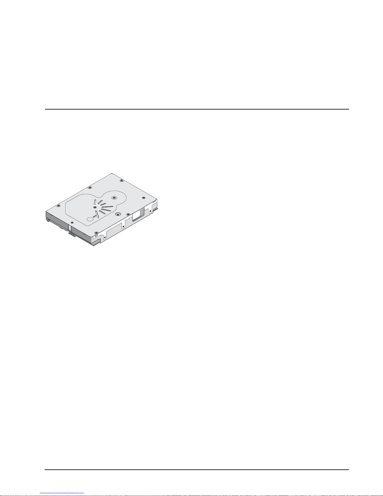
Figure 1. Cheetah 15K.4 SAS disc drive 1
Figure 2. Typical ST3146854SS drive +12V current profile. . . . . . . . . . . . . . . . . . . . . . . . . . . . . . . . . . . . . . . . . . . . . .28
Figure 3. Typical ST3146854SS drive +5V current profile. . . . . . . . . . . . . . . . . . . . . . . . . . . . . . . . . . . . . . . . . . . . . . .28
Figure 4. Typical ST373454SS drive +12V current profile . . . . . . . . . . . . . . . . . . . . . . . . . . . . . . . . . . . . . . . . . . . . . .29
Figure 5. Typical ST373454SS drive +5V current profile . . . . . . . . . . . . . . . . . . . . . . . . . . . . . . . . . . . . . . . . . . . . . . .29
Figure 6. Typical ST336754SS drive +12V current profile . . . . . . . . . . . . . . . . . . . . . . . . . . . . . . . . . . . . . . . . . . . . . .30
Figure 7. Typical ST336754SS drive +5V current profile. . . . . . . . . . . . . . . . . . . . . . . . . . . . . . . . . . . . . . . . . . . . . . . .30
Figure 8. ST3146854SS (3 Gbit) DC current and power vs. input/output operations per second . . . . . . . . . . . . . . . . .31
Figure 9. ST3146854SS (1.5 Gbit) DC current and power vs. input/output operations per second. . . . . . . . . . . . . . . .31
Figure 10. ST373454SS (3 Gbit) DC current and power vs. input/output operations per second . . . . . . . . . . . . . . . . . .32
Figure 11. ST373454SS (1.5 Gbit) DC current and power vs. input/output operations per second. . . . . . . . . . . . . . . . .32
Figure 12. ST336754SS (3 Gbit) DC current and power vs. input/output operations per second . . . . . . . . . . . . . . . . . .33
Figure 13. ST336754SS (1.5 Gbit) DC current and power vs. input/output operations per second. . . . . . . . . . . . . . . . .33
Figure 14. Location of the HDA temperature check point . . . . . . . . . . . . . . . . . . . . . . . . . . . . . . . . . . . . . . . . . . . . . . . .34
Figure 15. Recommended mounting . . . . . . . . . . . . . . . . . . . . . . . . . . . . . . . . . . . . . . . . . . . . . . . . . . . . . . . . . . . . . . . .36
Figure 16. Physical dimensions. . . . . . . . . . . . . . . . . . . . . . . . . . . . . . . . . . . . . . . . . . . . . . . . . . . . . . . . . . . . . . . . . . . .38
Figure 17. Physical interface . . . . . . . . . . . . . . . . . . . . . . . . . . . . . . . . . . . . . . . . . . . . . . . . . . . . . . . . . . . . . . . . . . . . . .41
Figure 18. Air flow . . . . . . . . . . . . . . . . . . . . . . . . . . . . . . . . . . . . . . . . . . . . . . . . . . . . . . . . . . . . . . . . . . . . . . . . . . . . . .42
Figure 19. Physical interface . . . . . . . . . . . . . . . . . . . . . . . . . . . . . . . . . . . . . . . . . . . . . . . . . . . . . . . . . . . . . . . . . . . . .57
Figure 20. SAS connector dimensions. . . . . . . . . . . . . . . . . . . . . . . . . . . . . . . . . . . . . . . . . . . . . . . . . . . . . . . . . . . . . . .58
Figure 21. SAS connector dimensions. . . . . . . . . . . . . . . . . . . . . . . . . . . . . . . . . . . . . . . . . . . . . . . . . . . . . . . . . . . . . . .59
Figure 22. SAS transmitters and receivers . . . . . . . . . . . . . . . . . . . . . . . . . . . . . . . . . . . . . . . . . . . . . . . . . . . . . . . . . . .61
Figure 23. Receive eye mask. . . . . . . . . . . . . . . . . . . . . . . . . . . . . . . . . . . . . . . . . . . . . . . . . . . . . . . . . . . . . . . . . . . . . .63
Figure 24. Reveive tolerance eye mask. . . . . . . . . . . . . . . . . . . . . . . . . . . . . . . . . . . . . . . . . . . . . . . . . . . . . . . . . . . . . .63
Figure 25. Sinusoidal jitter mask . . . . . . . . . . . . . . . . . . . . . . . . . . . . . . . . . . . . . . . . . . . . . . . . . . . . . . . . . . . . . . . . . . .64
Figure 26. Compliance interconnect test load . . . . . . . . . . . . . . . . . . . . . . . . . . . . . . . . . . . . . . . . . . . . . . . . . . . . . . . . .70
Figure 27. Zero-length test load. . . . . . . . . . . . . . . . . . . . . . . . . . . . . . . . . . . . . . . . . . . . . . . . . . . . . . . . . . . . . . . . . . . .70
Figure 28. ISI loss example at 3.0 Gbps . . . . . . . . . . . . . . . . . . . . . . . . . . . . . . . . . . . . . . . . . . . . . . . . . . . . . . . . . . . . .70
Figure 29. ISI loss example at 1.5 Gbps . . . . . . . . . . . . . . . . . . . . . . . . . . . . . . . . . . . . . . . . . . . . . . . . . . . . . . . . . . . . .71
Cheetah 15K.4 SAS Product Manual, Rev. B 1
Page 10

2 Cheetah 15K.4 SAS Product Manual, Rev. B
Page 11
1.0 Scope
This manual describes Seagate Technology® LLC, Cheetah® SAS (Serial Attached SCSI) disc drives.
Cheetah drives support the SAS Pr oto co l spec ifi cati ons to the exte nt de sc ribe d in this man ual . The SAS Inter-
face Manual (part number 100293071) describes t he general SAS characteri stics of this and other Se agate
SAS drives.
Figure 1. Cheetah 15K.4 SAS disc drive
Cheetah 15K.4 SAS Product Manual, Rev. B 1
Page 12

2 Cheetah 15K.4 SAS Product Manual, Rev. B
Page 13

2.0 Standards, compliance and reference documents
The drive has been developed as a system peripheral to the highest standards of design and construction. The
drive depends on its host equip ment to provide adequate power and e nvironment for optimum performa nce
and compliance with appl icable i ndustry and g overnme ntal regulations. Special attention mu st be given in the
areas of safety, power distribution, s hielding, audible n oise control, and temperature regulat ion. In particular,
the drive must be securely mo unted to guar antee the spe cified pe rformance char acterist ics. Mountin g by bot
tom holes must meet the requirements of Section 8.3.
2.1 Standards
The Cheetah SAS family com pl ies wi th Se aga te s tandar ds a s no ted in the app ropr iat e se cti on s of this ma nual
and the Seagate SAS Interface Manual, part number 100293071.
The Cheetah disc drive is a UL recognized component per UL1950, CSA certified to CAN/CSA C22.2 No. 950-
95, and VDE certified to VDE 0805 and EN60950.
2.1.1 Electromagnetic compatibility
The drive, as delivered , is designed for system integrati on and installation into a suitable encl osure prior to
use. The drive is supplied as a suba ssembly and is not subject to Sub part B of Part 15 of the FCC Rules and
Regulations nor the Radio Interference Regulations of the Canadian Department of Communications.
The design characteristics of the drive serve to minimize radiation when installed in an enclosure that provides
reasonable shielding. T he drive is ca pable of meeting the Cl ass B limits of the FCC Rules and Regulati ons of
the Canadian Department of C omm uni ca tio ns whe n p ro per ly pack ag ed; howe ve r, it is the user’s responsibil ity
to assure that the dri ve meets the approp riate EMI r equirements in thei r system. Sh ielded I/O c ables may be
required if the enclosure does not prov ide adequate shie lding. If the I/O cables are external to the enc losure,
shielded cables should be used, with the shields grounded to the enclosure and to the host controller.
-
2.1.1.1 Electromagnetic susceptibility
As a component a ssembly, the drive is not requ ired to meet any susc eptibi lity perfor mance requ irements. It is
the responsibilit y of those integrating the dr iv e wit hin the ir sy ste ms to pe rfo rm th os e te sts r eq ui red a nd des ig n
their system to ensure th at equipment operating in the same sy stem as the drive or external to the syste m
does not adversely affect the performance of the drive. See Tables
Cheetah 15K.4 SAS Product Manual, Rev. B 3
2 and 3, DC power requirements.
Page 14

2.2 Compliance
2.2.1 Electromagnetic compliance
Seagate uses an inde pendent laborato ry to confirm comp liance with the directives/standa rds for CE Markin g
and C-Tick Marking. The drive was tested in a representative system for typical applications. The selected sys
tem represents the most popular characteristics for test platforms. The system configurations include:
• Typical current use microprocessor
• 3.5-inch floppy disc drive
• Keyboard
• Monitor/display
• Printer
• External modem
•Mouse
Although the test system with this Seagate model complies with the directives/standards, we cannot guarantee
that all systems will comply. The computer manufacturer or system integrator shall confirm EMC compliance
and provide the appropriate marking for their product.
Electromagnetic compliance for the European Union
If this model has the CE Marking it co mplies with the European Union requirements of the El ectromagnetic
Compatibility Directive 89 /336/EEC of 03 May 1989 as amend ed by Dir ective 92 /31/ EEC of 28 Apri l 1992 an d
Directive 93/68/EEC of 22 July 1993.
-
Australian C-Tick
If this model has th e C-Tick Marking it complies with the Austr alia/New Zeal and Standard AS/NZS3548 199 5
and meets the Electromagnet ic Compatibility (EMC) Framework requi rements of Australia’s Spectrum Man
agement Agency (SMA).
Korean MIC
If this model has the Korean Ministry of Information and Communication (MIC) logo, it complies with paragraph
1 of Article 11 of the Electromagnetic Compatibility (EMC) Control Regulation and meets the Electroma gnetic
Compatibility Framework requirements of the Radio Research Laborator y (RRL) Ministry of Information and
Communication Republic of Korea.
Taiwanese BSMI
If this model has t wo Chine se words meani ng “E MC ce rtifica tion” follo wed by an eig ht digi t identifi catio n n umber, as a Marking, it complies with Chinese National Standard (CNS) 13438 and meets the Electromagnetic
Compatibility (EMC) Fra mework requ irements of the Taiwanese Bureau of Standards, Metrology, and Inspec
tion (BSMI).
-
-
4 Cheetah 15K.4 SAS Product Manual, Rev. B
Page 15

2.3 Reference documents
Cheetah 15K.4 SAS Installation Guide
Seagate part number: 100350602
SAS Interface Manual
ANSI SAS Documents
ANSI Small Computer System Interface (SCSI) Documents
Specification for Acoustic Test Requirement and Procedures
Package Test Specification
Package Test Specification
In case of conflict between this document and any referenced document, this document takes precedence.
Seagate part number: 100293071
SFF-8323 3.5” Drive Form Factor with Serial Connector
SFF-8460 HSS Backplane Design Guidelines
SFF-8470 Multi Lane Copper Connector
SFF-8482 SAS Plug Connector
ANSI INCITS.xxx Serial Attached SCSI (SAS) Standard (T10/1562-D)
ISO/IEC 14776-xxx SCSI Architecure Model-3 (SAM-3) Standard (T10/1561-D)
ISO/IEC 14776-xxx SCSI Primary Commands-3 (SPC-3) Standard (T10/1416-D)
ISO/IEC 14776-xxx SCSI Block Commands-2 (SBC-2) Standard (T10/1417-D)
X3.270-1996 (SCSI-3) Architecture Model
Seagate part number: 30553-001
Seagate P/N 30190-001 (under 100 lb.)
Seagate P/N 30191-001 (over 100 lb.)
Cheetah 15K.4 SAS Product Manual, Rev. B 5
Page 16

6 Cheetah 15K.4 SAS Product Manual, Rev. B
Page 17

3.0 General description
Cheetah drives combin e giant magnetoresisti ve (GMR) heads, partia l response/maximum likelihood (PRML)
read channel electroni cs, e mbedded servo te chnol ogy, and a Serial Attached SCSI (SA S) inter face t o provid e
high performance, h igh c apaci ty d ata s tor age f or a v ari ety o f sy st ems inc l uding engineering workstations, net
work servers, mainframes, and supercomputers. The Serial Attached SCSI interface is designed to meet next-
generation computing demands for performance, scalability, flexibility and high-density storage requirements.
Cheetah drives are rando m ac c ess s to ra ge d evic es de si gne d to support the Serial Attached SCS I P rotoc ol as
described in the ANSI spec ifications , this documen t, and the SAS Inte rface Manual ( part number 1002 93071)
which describes the g eneral interface characteristics o f this drive. Chee tah drives are classi fied as intelligen t
peripherals and provide level 2 confo rm ance ( hig hes t lev el) with the A NSI SC SI- 1 s tandard. Th e SA S connec
tors, cables and elec trical interface are com patible with Serial ATA (SATA), giving future user s the choice of
populating their systems with either SAS or SATA hard disc drives. This allows you to continue to leverage your
existing investment in SCSI while gaining a 3Gb/s serial data transfer rate.
The head and disc assembly (HD A) is sealed at the factory. Air recircul ates within the HDA through a non-
replaceable filter to maintain a contamination-free HDA environment.
Note. Never disassemb le the HDA and do not attemp t to service items in the sealed enclosure (heads,
media, actuator, etc.) as this requires special facilities. The drive does not contain user-replaceable
parts. Opening the HDA for any reason voids your warranty.
Cheetah drives use a dedicated landing zone at the innermost radius of the media to eliminate the possibility of
destroying or degrading data by landing in the data zone. The heads automatically go to the landing zone when
power is removed from the drive.
-
-
An automatic shipping lock prevents potential damage to the heads and discs that results from movement dur-
ing shipping and h andling. The shipping lock disengages and th e head load process be gins when power is
applied to the drive.
Cheetah drives decode track 0 location data from the servo data embedded on each surface to eliminate
mechanical transducer adjustments and related reliability concerns.
The drives also use a high-performance actuator assembly with a low-inertia, balanced, patented, straight arm
design that provides excellent performance with minimal power dissipation.
Cheetah 15K.4 SAS Product Manual, Rev. B 7
Page 18

3.1 Standard features
Cheetah drives have the following standard featur es:
• 1.5 / 3 Gbit Serial Attached SCSI (SAS) interface
• Integrated dual port SAS controller supporting the SCSI protocol
• Support for SAS expanders and fanout adapters
• Firmware downloadable using the SAS interface
• 64 - deep task set (queue)
• Supports up to 32 initiators
• Jumperless configuration.
• User-selectable logical block size (512 to 528 bytes per logical block) in any multiple of 4 bytes.
• Industry standard SFF 2.5-inch dimensions
• Programmable logical block reallocation scheme
• Flawed logical block reallocation at format time
• Programmable auto write and read reallocation
• Reallocation of defects on command (Post Format)
• ECC maximum burst correction length of 320 bits
• No preventive maintenance or adjustments required
• Dedicated head landing zone
• Embedded servo design
• Automatic shipping lock
• Embedded servo design
• Self diagnostics performed when power is applied to the drive
• Zone bit recording (ZBR )
• Vertical, horizontal, or top down mounting
• Dynamic spindle brake
• 8,192 Kbyte data buffer (see Section 4.5).
• Drive Self Test (DST)
• Background Media Scan (BGMS)
•Power Save
3.2 Media description
The media used on the drive has an alumi num sub st rat e co ated with a thin fi lm magn eti c mater ia l, over coate d
with a proprietary protective layer for improved durability and environmental protection.
3.3 Performance
• Programmable multi-segmentable cache buffer
• 300 Mbytes/sec maximum instantaneous data transfers.
• 15k RPM spindle. Average latency = 2.0 msec
• Background processing of queue
• Supports start and stop commands (spindle stops spinning)
• Adaptive seek velocity; improved seek performance
8 Cheetah 15K.4 SAS Product Manual, Rev. B
Page 19
3.4 Reliability
• Annualized Failure Rate (AFR) of 0.62%
• LSI circuitry
• Balanced low mass rotary voice coil actuator
• Incorporates industry-standard Self-Monitoring Analysis and Reporting Technology (S.M.A.R.T.)
• 5-year warranty
3.5 Formatted capacities
Standard OEM models are formatted to 512 bytes per block. The block size is sele ctable at format time an d
must be a multiple of 4 by tes. Users having the necessary equi pment may modify the data block size before
issuing a format command and obtain different formatted capacities than those listed.
To provide a stable target capacity environment and at the same time provide users with flexibility if they
choose, Seagate recommends product planning in one of two modes:
1. Seagate designs specify capacit y p oi nts at cer tain b lock siz es tha t S eag ate guarantees current and fut ur e
products will meet. We recommend custo mers use this capacity in their project pl anning, as it ensures a
stable operating point with backw ard and forward c ompatibi lity from gener ation to generati on. The curren t
guaranteed operating points for this product are:
Capacity (Blocks)
ST3146854SS ST373454SS ST336754SS
Sector Size
Decimal Hex Decimal Hex Decimal Hex
512 286,749,488 11177330 143,374,744 88BB998 71,687,372 445DCCC
514 282,050,768 10CFC0D0 141,025,384 867E068 70,512,692 433F034
520 280,790,184 10BC84A8 140,395,092 85E4254 70,197,546 42F212A
522 279,041,740 10A1D6CC 139,463,602 8500BB2 68,914,176 41B8C00
524 275,154,368 106685C0 137,577,184 83342E0 68,766,592 4194B80
2. Se aga te dri ve s a ls o m ay be u se d at the max im um av ail ab le c apacit y at a given block size, but the excess
capacity above the gua rantee d l ev el wi ll v ar y between other drive fami li es an d from generation to genera
tion, depending on how eac h block size actually formats out for zo ne frequencies and splits over servo
bursts. This added capaci ty potent ial may range from 0.1 to 1.3 percent above th e guarant eed capacities
listed above. Us ing th e dr ives in th is mann er gi ves the ab so lute m aximu m capacity poten tial, but the user
must determine if the extra ca pacity potential is useful, or whether their assurance of backward and for
ward compatibility takes precedenc e.
3.6 Programmable drive capacity
Using the Mode Select command, the drive can change its capacity to something less than maximum. See the
Mode Select (6) parameter list table in the SAS Interface Ma nual, part numb er 100293071. A value of z ero in
the Number of Blocks field indicates that the drive will not change the capacity it is currently formatted to have.
A number other than z er o a nd less tha n t he maximum number of L BA s in the Num ber of B lock s field c han ges
the tota l d rive capacity t o t he v al u e in t h e N umb er o f Bl o cks f ie l d. A v al u e gr ea t er t han t h e m ax im u m nu m be r of
LBAs is rounded down to the maximum capacity.
-
-
3.7 Factory-install ed accessories
OEM standard drives are shipped with the Cheetah 15K.4 SAS Installation Guide (part number 100350602).
Cheetah 15K.4 SAS Product Manual, Rev. B 9
Page 20

3.8 Factory-install ed options
You may order the following items which ar e incorporated at the manufac turing facility during produ ction or
packaged before shipping. Some of the options available are (not an exhaustive list of possible options):
• Other capacities can be ordered depending on sparing scheme and sector size requested.
• Single-unit shipping pack. The drive is normally shipped in bulk packaging to provide maximum protec tion
against transit damage. Units shipped individually require additional protection as provided by the single unit
shipping pack. Users planning single unit distribution should specify this option.
• The Cheetah 15K.4 SAS Installatio n Guid e, part numb er 1003 50602, is u suall y included with each standar d
OEM drive shipped, but extra copies may be ordered.
• The Safety and Regulatory Agency Specifications, part number 75789512, is usually included with each
standard OEM drive shipped, but extra copies may be ordered.
3.9 User-installed accessories
The following accessories are available. All kits may be installed in the field.
• Single-unit shipping pack.
10 Cheetah 15K.4 SAS Product Manual, Rev. B
Page 21

4.0 Performance characteristics
This section provides detailed information concerning performance-related characteristics and features of
Cheetah drives.
4.1 Internal drive characteristics
ST3146854SS ST373454SS ST336754SS
Drive capaci ty 146.8 73.4 36.7 Gbytes (formatted, rounded off value)
Read/write data heads 8 4 2
Bytes per track 471,916 471,916 471,916 Bytes (average, rounded off values)
Bytes per surface 18,351 18,351 18,351 Mbytes (unformatted, rounded off value)
Tracks per surface (total) 50,864 50,864 50,864 Tracks (user accessible)
Tracks per inch 85,000 85,000 85,000 TPI
Peak bits per inch 628 628 628 KBPI
Internal data rate 685-1,142 685-1,142 685-1,142 Mbits/sec (variable with zone)
Disc rotation speed 15k 15k 15k rpm
Avg rotational latency 2.0 2.0 2.0 msec
4.2 Seek performance characteristics
See Section 9.4.1, "SAS physical interface" on page 57 and the SAS Interface Manual (part number
100293071) for additional timing details.
4.2.1 Access time
Not Including controller overhead
(msec)
Read Write
Average Typical 3.5 4.0
Single track Typical 0.2 0.4
Full stroke Typical 7.4 7.9
1. Typical access times are measured under nominal conditions of temperature, voltage, and horizontal orientation as measured on a representative sample of drives.
2. Access to data = access time + latency time.
1, 2
Cheetah 15K.4 SAS Product Manual, Rev. B 11
Page 22

4.2.2 Format command execution time (minutes)
ST3146854SS ST373454SS ST336754SS
Maximum (with verify)
Maximum (without veri fy )
90 60 30
45 30 15
4.2.3 General performance characteristics
Minimum sect or interleave 1 to 1
Data buffer to/from disc media (one 512-byte logical block)*
Minimum 685 Mbits/sec
Maximum 1,142 Mbits/sec
SAS Interface maximum instantaneous transfer rate 300 Mbytes/sec* per port
Logical block sizes
Default is 512-byte data blocks
Variable 512 to 704 byt es per sector in even number of bytes per sector. If n (number
of bytes per sector) is odd, then n-1 will be used.
Read/write consecutive sectors on a track Yes
Flaw reallocation performance impact (for flaws reallocated at format time using
the spare sectors per sparing zone reallocation scheme.)
Average rotation al lat enc y 2.0 msec
*Assumes no errors and no relocated logical blocks. Rate measured from the start of the first logical block transfer to or
from the host.
(dual port = 600 Mbytes/sec*)
Negligible
4.3 Start/stop time
The drive accepts the comma nds list ed in the SAS Inte rface Man ual less than 3 seconds after DC power has
been applied.
If the drive receives a NOTIFY (ENABLE SPINUP) primitive through either port and has not received a START
STOP UNIT command with the START bit equal to 0, the drive becomes ready for normal operations within 20
seconds (excluding the error recovery procedure).
If the drive receives a START STOP UNIT command with the START bit equal to 0 before receiving a NOTIFY
(ENABLE SPINUP) primitive, the drive waits for a START STOP UNIT command with the START bit equal to 1.
After receiving a START STOP UNIT command with the START bit equal to 1, the drive waits for a N OTIFY
(ENABLE SPINUP) primit ive. After receiving a NOTIFY (ENA BLE SPINUP) primitive throu gh either port, the
drive becomes ready for normal operations within 20 seconds (excluding the error recovery procedure).
12 Cheetah 15K.4 SAS Product Manual, Rev. B
Page 23

If the drive receives a START STOP UNIT command with the START bit and IMMED bit equal to 1 and d oes
not receive a NOTIFY (ENABL E SPINUP) primitive within 5 seco nds, the drive fails the START STOP UNIT
command.
The START STOP UNIT command may be used to command the drive to stop the spindle. Stop time is 30 seconds (maximum) from removal of DC power. There is no power control switch on the drive.
4.4 Prefetch/multi-segmented cache control
The drive provides a prefetch ( read look-ahead) and multi-se gmented cache control algori thms that in many
cases can enhan ce system performance. Cac he refers to the drive buffer stor age space when it is used in
cache operations . To select this feature, th e host sends the Mode Select command with the p roper values in
the applicable bytes in page 08h. Prefetch and cache operations are independent features from the standpoint
that each is enabled and dis abled indepe ndently using the Mode Select c ommand; however, in actual opera
tion, the prefetch feature overlaps cache operation somewhat as described in sections 4.5.1 and 4.5.2.
All default cache and prefetch mode paramete r values (Mode Page 08 h) for standard OEM versions of this
drive family are given in Table
9.3.2.1.
4.5 Cache operation
Note. Refer to the SAS Interface Manual for more detail concerning the cache bits.
Of the 8,192 kbytes p hysical buffer space in the dri ve, approximately 7,077 kbytes can be u sed as a cache.
The buffer can be divided into logical segments (using Mode Select Page 08h, byte 13) from which data is read
and to which data is written.
-
The drive keeps track of the logical block addresses of the data stor ed in each segment of the buffer. If the
cache is enabled (see RCD bit in the SAS Interface Manual
), data requested by the host with a read command
is retrieved from the buffer, if possible, before any disc access is initiated. If cache operation is not enabled, the
buffer (still segmented with the required number of segments) is still used, but only as circular buffer segments
during disc medium read oper ations (di sregardin g Prefetch oper ation for th e moment). That i s, the drive does
not check in the buffer segments for the requested read data, but goes directly to the medium to retrieve it. The
retrieved data merely passes throug h some buffer seg ment on the wa y to the hos t. On a c ache miss, all data
transfers to the host are in accorda nce with bu ffer-full ratio rules. On a c ache hit , the drive ig nores the bufferfull ratio rules. See the explanation provided with the information about Mode Page 02h (disconnect/reconnect
control) in the SAS Interface Manual.
The following is a simplified description of the prefetch/cache operation:
Case A—read command is received and the first logical block is already in the cache:
1. Drive transfers to the initiator the first logical block requested plus all subsequent contiguous logical blocks
that are already in the cache. This data may be in multiple segments.
2. Wh en a requested logical block is reached that is not in any cache se gment, the d rive fetches it and any
remaining requested lo gical b lock a ddres ses from th e disc and puts them in a seg ment o f the cache . The
drive transfers the r emaining requested logical blocks from t he cache to the host in a ccordance with the
Mode Select Disconnect/Reconnect parameters, page 02h.
3. If the prefetch feature is enabled, refer to section 4.5.2 for operation from this point.
Case B—A Read command requests data, and the first logical block is not in any segment of the cache:
1. The drive fetc hes the req uested lo gical bloc ks from t he disc and transfers them int o a segme nt, and the n
from there to the host in accordance with the Mode Select Disconnect/Reconnect parameters, page 02h.
2. If the prefetch feature is enabled, refer to section 4.5.2 for operation from this point.
Cheetah 15K.4 SAS Product Manual, Rev. B 13
Page 24

During a prefetch, the drive cross es a cylinder boundary to fetc h data only if the Disco ntinui ty (DISC) bit is se t
to 1 in bit 4 of byte 2 of the Mode Select parameters page 08h. Default is zero for bit 4.
Each cache se gment is actually a s elf-contained circula r buffer whose length is an integer number of logical
blocks. The wrap-ar ound capability of the individual segm ents greatly enhances the cache’s overa ll perfor
mance, allowing a wide range of user-sele ctable configurations. The d rive supports operation of any integer
number of segments from 1 to 16. D ivide the 7 ,077 Kbyt es in the b uffer by the numbe r of seg ments to get the
segment size. Default is 3 segments.
Note. The size of eac h segment is not reported by Mode Sense command page 08h, bytes 14 and 15.
The value 0XFFFF is always reported regardless of the actual size of the segm ent . Se ndi ng a siz e
specification using the Mode Select command (byt es 14 and 15) does not set up a new segment
size. If the STRICT bit in Mode page 00h (byte 2, bit 1) is set to one , the driv e respon ds as it does
for any attempt to change an unchangeable parameter.
4.5.1 Caching write data
Write caching is a write operation by the drive th at mak es u se of a drive buffer storage ar ea wher e the da ta to
be written to the medium is stored while the drive performs the Write command.
If read caching is enabled (RCD=0), then data written to the medium is retained in the cache to be made available for future read cache hits. The s ame buffer space an d segme ntation is use d as set up for read func tions.
The buffer segmentation s cheme is set up or changed independently, having nothing to do with the state of
RCD. When a write command is issued, i f RCD=0, the cache is first checke d to see if any logical blocks tha t
are to be written are a lready stored in the cache f rom a previous read or write comman d. If there are, the
respective cache segments are cleared. The new data is cached for subsequent Read commands.
-
If the number of write data logical blocks exceed the size of the segment being written into, when the end of the
segment is reached, the data is written into the beginning of the same cache segment, overwriting the data that
was written there at the beginning of the operation; however, the drive does not overwrite data that has not yet
been written to the medium.
If write caching is enabled (WCE=1), then the drive may return Good status on a write command after the data
has been transferred into the cache, but befor e the data has been written to the medium. If an error oc curs
while writing the data to the medium, and Good status has already been returned, a deferred error will be gen
erated.
The Synchronize Cache command may be used to force the drive to write all cached write data to the medium.
Upon completion of a Synchronize Cache command, all data received from previous write commands will have
been written to the medium.
Table 9.3.2.1 shows the mode default settings for the drive.
4.5.2 Prefetch operation
If the Prefetch fea ture i s ena bl ed, data in co nti guo us lo gic al b lock s on t he d is c immediately beyond tha t whi c h
was requested by a Read c ommand are retrieved and stored in the buffer for immediate transfer from the
buffer to the host on subseque nt Read com mands that request t hose logica l block s (this is tr ue even if cache
operation is disabled). Though the prefetch operation uses the buffer as a cache, finding the requested data in
the buffer is a prefetch hit, not a cache operation hit.
To enable Prefetch, use Mod e Select page 08h, byte 12, bit 5 (Di sable Read Ahead - DRA bit). DRA bit = 0
enables prefetch.
-
Since data that is pr efetch ed r eplaces data alr eady in som e b uffer segmen ts, the ho st can limit the a mount o f
prefetch data to optimize system per formance. The Max Prefetch field (bytes 8 and 9) limits the amount of
prefetch. The drive does not use the Prefetch Ceiling field (bytes 10 and 11).
14 Cheetah 15K.4 SAS Product Manual, Rev. B
Page 25

During a prefetch operation, the drive cros ses a cylinder boundary to fetch more data only if Mode paramete rs
page 08h, byte 2, bit 4 is set to 1 (Discontinuity--DISC bit).
When prefetch (read look -ahead) is enabled (enabled by DRA = 0), it opera tes under the control of ARLA
(Adaptive Read Look-Ahead). If the host uses software interleave, ARLA enables prefetch of contiguous
blocks from the disc when it senses that a prefetch hit will likely occur, even if two consecutive read operations
were not for physically co ntiguous blocks of data (e.g. “software interleave ”). ARLA disables pr efetch when it
decides that a prefetch hit will not likely occur. If the host is not using software interleave, and if two sequential
read operations are no t for c ontigu ous bloc ks of data, ARLA d isables prefetc h, but as long as se quentia l read
operations request contiguous blocks of data, ARLA keeps prefetch enabled.
4.5.3 Optimizing cache performance for desktop and server applications
Desktop and server applications require different drive caching operations for optimal performance. This
means it is difficult to provide a single configuration that meets both of these needs. In a desktop environment,
you want to con figure the cache to respond q uickly to repetitive ac cesses of multiple s mall segmen ts of data
without taking the time to “look ahea d” to the next conti guous segmen ts of data. In a server environ ment, you
want to configure the cac he to provide large volumes of seque ntial data in a non-repetitive manner. In this
case, the ability of the cache to “look ahead” to the next contiguous segmen ts of sequential data is a good
thing.
The Performance Mode (PM) bit contr ols the way the drive switches the cache buffer into different modes o f
segmentation. In “server mode” (PM bit = 0), the drive can dynamically cha nge the number of cache buffer
segments as needed to opt imize the performa nce, based on the command st ream from the hos t. In “desktop
mode” (PM bit = 1), the number of segments is maintained at the value defined in Mode Page 8, Byte 13, at all
times (unless changed by using a Mode Select command). For additional information about the PM bit, refer to
the Unit Attention Pa rameters page (00h) of the Mod e Sense command (1Ah) in the SAS Interface Manual,
part number 100293071.
Cheetah 15K.4 SAS Product Manual, Rev. B 15
Page 26

16 Cheetah 15K.4 SAS Product Manual, Rev. B
Page 27

5.0 Reliability specifications
The following reli ability specifica tions assume co rrect host and drive operational interfa ce, including al l interface timings, power supply voltages, environmental requirements and drive mounting constraints.
Seek error rate: Less than 10 errors in 108 seeks
Read Error Rates
Recovered Data Less than 10 errors in 1012 bits transferred (OEM default settings)
Unrecovered Data Less than 1 sector in 1015 bits transferred
Miscorrected Data Less than 1 sector in 1021 bits transferred
Interface error rate: Less than 1 error in 1012 bits transferred
Annualized Failure Rate (AFR): 0.62% (see section 5.2.1)
Service Life 5 years
Preventive maintenance: None required
1. Error rate specified with automatic retries and data correction with ECC enabled and all flaws reallocated.
5.1 Error rates
The error rates stated in this manual assume the following:
• The drive is operated in accordance with this manual using DC p ower as defined in paragraph 6.2, "DC
power requirements."
• Errors caused by host system failures are excluded from error rate computations.
• Assume random data.
• Default OEM error recovery settings are applied. This includes AWRE, ARR E, full read retries, full write
retries and full retry time.
1
5.1.1 Recoverable Errors
Recovereable errors are those detected and corrected by the drive, and do not require user intervention.
Recoverable Data errors will use co rrection, although ECC on -the-fly is not c onsidered for purposes of recov-
ered error specifica tio ns.
Recovered Data error rate is determine d using read bits transfer red for recove rable errors occurring dur ing a
read, and using write bits transferred for recoverable errors occurring during a write.
5.1.2 Unrecoverable Erro rs
An unrecoverable data erro r is defined as a fail ure of the drive to rec over data from the me dia. These errors
occur due to head/medi a or write problems . Unrecoverable data errors are only detected du ring read opera
tions, but not caused by the r ead. If an unrec overable data erro r is detected, a ME DIUM ERROR (03 h) in the
Sense Key will be reported. Multiple unrecoverable data errors resulting from the same cause are treated are 1
error.
Cheetah 15K.4 SAS Product Manual, Rev. B 17
-
Page 28

5.1.3 Seek errors
A seek error is defined as a fail ur e of the dr i ve to pos it ion the heads to the addressed track. After detecting an
initial seek error, the drive automatically performs an error recovery process. If the error recovery process fails,
a seek positioning error (Error code = 15h or 02h) will be reporte d with a Hardware error (04h) in t he Sense
Key. Recoverab le seek er rors are sp ecifi ed at Less than 10 erro rs in 10
8
seeks. Unrecoverable seek errors
(Sense Key = 04h) are classified as drive failures.
5.1.4 Interface errors
An interface error is defin ed as a failure of the receiver on a port to recover the d ata as transmitted by the
device port connected to the receiver. The error may be detected as a running disparity error, illegal code, loss
of word sync, or CRC error.
5.2 Reliability and service
You can enhance the r eliability of Cheetah disc drives by ensuring that the drive recei ves adequate cooling.
Section 6.0 provides te mperature mea surements and othe r informatio n that may be used to en hance the service life of the drive. Section 8.2 provides recommended air-flow information.
5.2.1 Annualized Failure Rate (AFR)
The production disc dr ive shall achieve an AFR of 0.62% when oper ated in an environmen t that ensures the
HDA case temperatur es spec ified in Sectio n 6. 4 are not exce eded. S hort -term ex cursi ons u p to th e spec ification limits of the operating e nvironment will not affect AFR perfor mance. Continual or sustained operation at
case temperatures above the values shown in Section 6.4.1 may degrade product reliability.
Estimated power-on operation hours means power-up hours per disc drive times the total number of disc
drives in service. Ea ch dis c drive shall h ave accu mulate d at le ast nine months of operatio n. Data sha ll be ca lculated on a rolling average base for a minimum period of six months.
AFR is based on the following assumption s:
• 8,760 power-on hours per year.
• 250 average on/off cycles per year.
• Operations at nominal voltages.
• Systems will provide adequa te cooling to ensure the case temper atures specified in Section 6.4.1 are not
exceeded.
Drive failure means any stoppage or substandard performance caused by drive malfunction.
A S.M.A.R.T. predictive fail ure indic ates that the dri ve is deter iorating to an immin ent failu re and is co nside red
an AFR hit.
5.2.2 Preventive maintenance
No routine scheduled preventive maintenance is required.
5.2.3 Hot plugging the drive
When a disc is powered on by switchin g the powe r or hot plugged, the drive run s a self test befor e attemp ting
to communicate o n its’ interfaces. When the self test co mpletes successfull y, the drive initiates a Link R eset
starting with OOB. An attached devic e should respond to the link rese t. If the link reset attempt fails, or any
time the drive looses sync, the drive initiated l ink reset. The drive will i nitiate link reset once p er second but
alternates between por t A and B. Therefor e each port will atte mpt a link reset on ce per 2 seconds assuming
both ports are out of sync..
If the self-test fails, the does not respond to link reset on the failing port.
18 Cheetah 15K.4 SAS Product Manual, Rev. B
Page 29

Note. It is the respon si bi li ty o f the sy s tems in tegrator to assure that no tem per atu re, energy, voltage haz-
ard, or ESD potential haza rd is presented dur ing the hot connect/di sconnect oper ation. Discharge
the static electricity from the drive carrier prior to inserting it into the system.
Caution. The drive motor must come to a complete stop prior to changing the plane of operation. This time is
required to insure data integrity.
5.2.4 S.M.A.R.T.
S.M.A.R.T. is an acronym for Se lf-Moni toring Analy sis and Repor ting Technology. This technology is intende d
to recognize conditio ns that indicate imminent drive failure and is desig ned to provide sufficient warn ing of a
failure to allow you to back up the data before an actual failure occurs.
Note. The drive’s firmware monitors specific attributes for degradation over time but can’t predict instanta-
neous drive failures.
Each monitored a ttrib ute has b een sele cted to moni tor a specifi c se t of fai lure c onditi ons in th e oper ating per formance of the drive and the thresholds are optimized to minimize “false” and “failed” predictions.
Controlling S.M.A.R.T.
The operating mode of S.M.A.R.T. is controlled by the DEXCPT and PERF bits on the Informational Exceptions
Control mode page (1Ch). Use th e DEXCPT bit to ena ble or disab le the S.M.A.R. T. feature. Se tting the DE X
CPT bit disables all S.M.A.R.T. functions. When enabled, S.M.A.R.T. collects on-line data as the drive performs
normal read and write operations. When the PERF bit is set, the drive is consi dered to be in “On-line Mod e
Only” and will not perform off-line functions.
-
You can measur e off-line attributes a nd force the dri ve to save the data by using the Rez ero Unit command .
Forcing S.M.A.R.T. resets the timer so that the next scheduled interrupt is in two hours.
You can interrogate the drive through the host to determine the time remaining before the next scheduled measurement and data logging process occurs. To accomplish this, issue a Log Sense command to log page 0x3E.
This allows you to c ontrol when S.M.A.R.T. interruptions occ ur. Forcing S.M.A.R.T. with the RTZ command
resets the timer.
Performance impact
S.M.A.R.T. attribute data is saved to the disc so that the events that caused a predi ctive failure can be recreated. The drive measures and saves paramete rs once every two hour s subject to an idle pe riod on the drive
interfaces. The pro cess o f meas uring off-line attribute data a nd sa ving data to th e disc is u ninterr uptable. Th e
maximum on-line only processing delay is summarized below:
Maximum processing delay
S.M.A.R.T. delay times
On-line only delay
DEXCPT = 0, PERF = 1
50 milliseconds
Fully-enabled delay
DEXCPT = 0, PERF = 0
300 milliseconds
Cheetah 15K.4 SAS Product Manual, Rev. B 19
Page 30

Reporting control
Reporting is controlled by the MRIE bits in the Inform ational Exceptio ns Control mode page (1Ch). Subject to
the reporting metho d, t he firmw are w ill is sue to the h ost a n 0 1-5Dxx sense code. The error code is pr eserve d
through bus resets and power cycles.
Determining rate
S.M.A.R.T . monitors the rate at which errors occur and signals a predictive failure if the rate of degraded errors
increases to an unacceptable level. To determine rate, error events are logged and compared to the number of
total operations for a given attribu te. The in terval de fine s the numb er of operati ons over which to mea sure the
rate. The counter that keeps track of the current number of operations is referred to as the Interval Counter.
S.M.A.R.T. measures error rates. All errors for each monitored attribute are recorded. A counter keeps track of
the number of errors for the current interval. This counter is referred to as the Failure Counter.
Error rate is the number of errors per operation. The algorithm that S.M.A.R.T. uses to record rates of error is to
set thresholds for the number of errors an d their inte rval. If the nu mber of error s exceed s the thr eshold bef ore
the interval expires, the error rate i s considered to be unacc eptable. If the number of errors does not exceed
the threshold before the interval expires, the error rate is considered to be acceptable. In either case, the inter
val and failure counters are reset and the process starts over.
Predictive failures
S.M.A.R.T. signals predict ive failures when the dri ve is perfor ming unacc eptably for a period of time. Th e firmware keeps a running count of the number of times the error rate for each attribute is unacceptable. To accomplish this, a cou nter is i ncremen ted each time the error rat e is un acceptable and decr emented (not to e xceed
zero) whenever t he error ra te is a cceptabl e. If the co unter contin ually in crem ents such that it reache s the pr e
dictive threshol d, a predictive failure is signaled. This counter is r eferred to as the Failure H istory Counter.
There is a separate Failure History Counter for each attribute.
-
-
5.2.5 Thermal monitor
Cheetah drives implement a temperature warning sy s tem whic h:
1. Signals the host if the temperature exceeds a value which would threaten the drive.
2. Signals the host if the temperature exceeds a user-specified value.
3. Saves a S.M.A.R.T. data frame on the drive which exceeds the threatening temperature value.
A temperature sensor monito rs the drive temperature and is sues a warning over the int erface when the temperature exceeds a s et threshol d. The temper ature is measured at power-up an d then at te n-minute intervals
after power-up.
The thermal monitor syste m generates a warn ing code of 01- 0B01 when the temp erature exceeds th e specified limit in compl iance with the SCSI standard. T he drive temperature is repo rted in the FRU code field o f
mode sense data. You can use this information to determine if the warning is due to the temperature exceeding
the drive threatening temperature or the user-specified temperature.
This feature is controlled by the Enable Warning (EWasc) bit, and the reporting mechanism is controlled by the
Method of Reporting Informational Exceptions field (MRIE) on the Informational Exceptions Control (IEC)
mode page (1Ch).
The current algorithm impl ements two temperature trip points. The first trip point is set at 65°C which is the
maximum temperatur e limit a ccordi ng to th e dri ve spec ific ation. Th e seco nd trip point is us er-se lectable using
the Log Select command. The reference temperature parameter in the temperature log page (see Table
1) can
20 Cheetah 15K.4 SAS Product Manual, Rev. B
Page 31

be used to set this trip point. The default value for this drive is 65°C, however, you can set it to any value in the
range of 0 to 65°C. If you specify a temperature g reater than 65°C in this fi eld, the temperature is rou nded
down to 65°C. A sense code is sent to the host to indicate the rounding of the parameter field.
Table 1: Temperature Log Page (0Dh)
Parameter Code Description
0000h
0001h
Primary Temperature
Reference Temperature
5.2.6 Drive Self Test (DST)
Drive Self Test (DST) is a technology designed to recog nize drive fault conditions that qualify the drive as a
failed unit. DST validates the functionality of the drive at a system level.
There are two test coverage options implemented in DST:
1. Extended test
2. Short text
The most thorough option is the extended test that performs various tests on the drive and scans every logical
block address (LBA ) of the drive. The s hort test is time-r estricted and limited i n length—it does n ot scan the
entire media surface, but does some fundamental tests and scans portions of the media.
If DST encounters an er ror during either of these tests, i t reports a fault condition. If the driv e fails the test,
remove it from service and return it to Seagate for service.
5.2.6.1 DST failure definition
The drive will presen t a “diagnostic failed” con dition through the self-te sts results value of the diagnos tic log
page if a functional failur e is enco untered du ring DST. The channel and servo parameters are not mod ified to
test the drive more strin gently, and the number of retries are not redu ced. All retries and recovery proce sses
are enabled during the test. If data is recoverable, no failure condition will be reported regardless of the number
of retries required to recover the data.
The following conditions are considered DST failure conditions:
• Seek error after retries are exhausted
• Track-follow error after retries are exhausted
• Read error after retries are exhausted
• Write error after retries are exhausted
Recovered errors will not be reported as diagnostic failures.
5.2.6.2 Implementation
This section provides all of the information necessary to implement the DST function on this drive.
Cheetah 15K.4 SAS Product Manual, Rev. B 21
Page 32

5.2.6.2.1 State of the drive prior to testing
The drive must be in a ready state before issuing the Send Diagno stic command . There are multipl e reasons
why a drive may not be ready, some of which are valid conditions, and not errors. For example, a drive may be
in process of doing a format, or another DST . It is the responsibility of the host application to determine the “not
ready” cause.
While not technically part of DST, a Not Ready condition also qualifies the drive to be returned to Seagate as a
failed drive.
A Drive Not Ready condition is reported by the drive under the following conditions:
• Motor will not spin
• Motor will not lock to speed
• Servo will not lock on track
• Drive cannot read configuration tables from the disc
In these conditions, the drive responds to a Test Unit Ready command with an 02/04/00 or 02/04/03 code.
5.2.6.2.2 Invoking DST
To invoke DST, submit th e Send Dia gnostic com mand with th e appropria te Function Code (001b for the shor t
test or 010b for the extended test) in bytes 1, bits 5, 6, and 7.
5.2.6.2.3 Short and extended tests
DST has two testing options:
1. short
2. extended
These testing options are described in the following two subsections.
Each test consists of th ree s egm ents: a n el ec tric al test segm ent, a servo test segment , and a re a d/ver ify sca n
segment.
Short test (Function Code: 001b)
The purpose of the short test is to prov ide a ti me- l imi ted te st tha t tests as much of the drive as poss ib le wi thi n
120 seconds. The shor t test does not scan the entire me dia surface, but does some fu ndamental tests and
scans portions of the media. A complete read/verify scan is not performed and only factual failures will report a
fault condition. This option provides a quick confidence test of the drive.
Extended test (Function Code: 010b)
The objective of the extended test option is to empirically test critical drive components. For example, the seek
tests and on-track operations tes t the pos it ion ing mec han ism. T he read op erati on tes ts the read hea d ele men t
and the media surface. The write element is tested throu gh read/write/read operations. The inte grity of the
media is checked through a r ead/verif y scan of the med ia. Motor functio nality is tested by d efault as a part of
these tests.
The anticipated length of the Extended test is reported through the Control Mode page.
5.2.6.2.4 Log page entries
When the drive begi ns DST, it creates a new entry in the Se lf -test Res ul ts Log page. T he new entry is cr eate d
by inserting a new self-test parameter block at the beginning of the self-test results log parameter section of the
log page. Existing d ata will be moved to make ro om f or the new param eter b lock . T he driv e r ep or ts 20 param
eter blocks in the log page. If there are more than 20 parameter blocks, the least recent parameter block will be
deleted. The new parameter block will be initialized as follows:
1. The Function Code field is set to the same value as sent in the DST command
-
22 Cheetah 15K.4 SAS Product Manual, Rev. B
Page 33

2. The Self-Test Results Value field is set to Fh
3. The drive will store the log page to non-volatile memory
After a self-test is complete or has been aborted, the dr i ve upda tes the Self-Test Results Value field in its Self-
Test Results Log page in non-v ola til e m emo ry. The host may use Log Se nse to re ad th e r es ults from up to th e
last 20 self-tests performed by the drive. The self-test results value is a 4-bit field that reports the results of the
test. If the field is set to zero, the drive passed with no errors detected by the DST. If the field is not set to zero,
the test failed for the reason reported in the field.
The drive will report th e failure condition and LBA (i f applicable) in the Self-tes t Results Log parameter. The
Sense key, ASC, ASCQ, and FRU are used to report the failure condition.
5.2.6.2.5 Abort
There are several ways to abort a diagnostic. You can use a SCSI Bus Reset or a Bus Device Reset message
to abort the diagnostic.
You can abort a DST ex ecuting in b ackground m ode by us ing the abort c ode in the DS T Function Cod e field.
This will cause a 01 ( self-test aborted b y the application cl ient) code to appear i n the self-test results v alues
log. All other abort mechanisms will be reported as a 02 (self-test routine was interrupted by a reset condition).
5.2.7 Product warranty
Beginning on the da te of shipment to the customer and contin uing for the period spe cified in your purchas e
contract, Seagate wa rra nts that e ach pro duct (i nclud ing com pon ents and su basse mblie s) that fails t o fu nction
properly under normal use due to defect in materials or workmanship or due to nonconformance to the applica
ble specifications will be repaired or replaced, at Seagate’s option and at no charge to the customer, if returned
by customer at cus tomer’s expense to S eagate’s designated facility in ac cordance with Seagate’s warranty
procedure. Seagate will pay for tr an sp or tin g th e repa ir or rep lac em ent ite m t o th e c us tome r. For more detailed
warranty information, refer to the standard terms and conditions of purchase for Seagate products on your pur
chase documentation.
-
-
The remaining warranty for a particular drive can be determined by calling Seagate Customer Service at
1-800-468-3472. You can also determine remain ing war ranty using the Seagate web si te (www.seagate.com) .
The drive serial number is required to determine remaining warranty information.
Shipping
When transporting or shipping a drive, use only a Seagate-approved container. Keep your original box.
Seagate approved containers are easily identified by the Seagate Approved Package label. Shipping a drive in
a non-approved container voids the drive warranty.
Seagate repair centers may refus e rece ipt of compo nents impro perly packaged or obviou sly damag ed in transit. Contact your author ized Seag ate distr ibutor to purchas e additio nal boxe s. Seagat e recom mends sh ipping
by an air-ride carrier experienced in handling computer equipment.
Product repair and return information
Seagate customer se rvice centers are th e only facilities au thorized to service S eagate drives. Seag ate does
not sanction any third-party repair facilities. Any unauthorized repair or tamper ing with the factory seal voids
the warranty.
Cheetah 15K.4 SAS Product Manual, Rev. B 23
Page 34

24 Cheetah 15K.4 SAS Product Manual, Rev. B
Page 35

6.0 Physical/electrical spe cifications
This section provides information relating to the physical and electrical characteristics of the drive.
6.1 AC power requirements
None.
6.2 DC power requirements
The voltage and current requi rements for a single drive are shown below. Values indicated apply at the drive
connector.
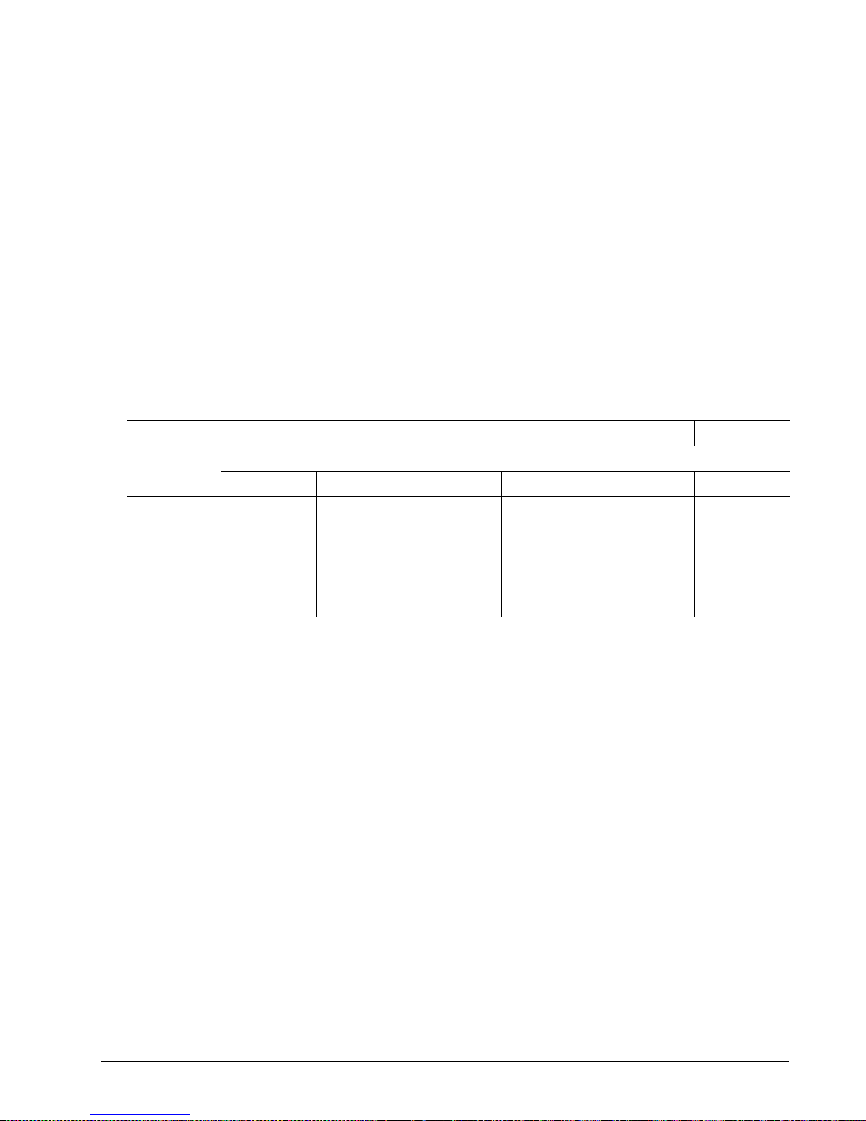
Table 2: ST3146854SS DC power requirements
ST3146854SS
3 Gbit mode
Notes
Voltage +5V +12V [2] +5V +12V [2]
Regulation [5] ±5% ±5% [2] ±5% ±5% [2]
Avg idle current DCX [1] [7] 1.02 0.77 1.08 0.77
Maximum starting current
(peak DC) DC 3σ [3] 1.21 1.82 1.23 1.82
(peak AC) AC 3σ [3] 1.67 3.89 1.67 3.88
Delayed motor start (max) DC 3σ [1] [4] 1.03 0.04 1.02 0.04
Peak operating current:
Typical DCX [1] [6] 1.12 1.17 1.04 1.17
Maximum DC 3σ [1] 1.15 1.19 1.12 1.20
Maximum (peak) DC 3s 1.70 2.86 1.70 2.90
(Amps) (Amps) (Amps) (Amps)
ST3146854SS
1.5 Gbit mode
Cheetah 15K.4 SAS Product Manual, Rev. B 25
Page 36

Table 3: ST373454SS DC power requirements
ST373454SS
3 Gbit mode
Notes
Voltage +5V +12V [2] +5V +12V [2]
Regulation [5] ±5% ±5% [2] ±5% ±5% [2]
Avg idle current DCX [1] [7] 1.02 0.56 1.07 0.56
Maximum starting current
(peak DC) DC 3σ [3] 1.20 1.76 1.21 1.78
(peak AC) AC 3σ [3] 1.62 3.79 1.56 3.87
Delayed motor start (max) DC 3σ [1] [4] 1.03 0.04 0.91 0.04
Peak operating current:
Typical DCX [1] [6] 1.12 0.95 1.00 0.94
Maximum DC 3σ [1] 1.13 0.96 1.02 0.96
Maximum (peak) DC 3s 1.64 2.70 1.52 2.74
(Amps) (Amps) (Amps) (Amps)
ST373454SS
1.5 Gbit mode
Table 4: ST336754SSDC power requirements
ST336754SS
3 Gbit mode
Notes
Voltage +5V +12V [2] +5V +12V [2]
Regulation [5] ±5% ±5% [2] ±5% ±5% [2]
Avg idle current DCX [1] [7] 1.01 0.44 1.07 0.44
Maximum starting current
(peak DC) DC 3σ [3] 1.17 1.58 1.20 1.59
(peak AC) AC 3σ [3] 1.65 3.43 1.52 3.39
Delayed motor start (max) DC 3σ [1] [4] 1.02 0.04 0.91 0.04
Peak operating current:
Typical DCX [1] [6] 1.12 0.83 1.01 0.83
Maximum DC 3σ [1] 1.14 0.85 1.02 0.85
Maximum (peak) DC 3s 1.64 2.56 1.52 2.58
(Amps) (Amps) (Amps) (Amps)
ST336754SS
1.5 Gbit mode
[1] Measured with average reading DC ammet er. Instantaneous +12V current peaks wi ll exceed these val-
ues. Power supply at nominal voltage. N (number of drives tested) = 6, 35 Degrees C ambient.
[2] For +12 V, a –10% toler an ce is a llowed du ri ng in iti al sp in dle s tart bu t m ust retu rn to ±5% before re ac hin g
14,904 RPM. The ±5% must be maintained after the drive signifi es that its power-up sequen ce has bee n
completed and that the drive is able to accept selection by the host initiator.
[3] See +12V current profile in Figure 2.
26 Cheetah 15K.4 SAS Product Manual, Rev. B
Page 37

[4] This condition occurs after OOB and Speed Negotiation compl etes but b efore the dr ive has r eceived th e
Notify Spinup primitive.
[5] See paragraph 6.2.1, "Conducted noise immunity." Specified voltage toleran ce in cl ud es rip ple, noise, and
transient response.
[6] Operating condition is defined as random 8 block reads with 225 I/Os per second for ST3146854SS
drives, 230 I/Os per se cond for ST373454SS dr ives, and 230 I/Os per se cond for ST336754SS dr ives.
Current and power sp ecified at no minal voltages . Decreasi ng +5 volt s upply by 5 % increase s 5 volt cur
rent by 2.5%. Decreasing +12 volt supply by 5% i ncreases 12 volt current by 3.0% for ST3146854SS
models, 2.0% for ST3734 54S S mod els , and 2 .0% for ST336754SS models.
[7] During idle, the drive he ads are relocated every 60 seconds to a random location within the band from
three-quarters to maximum track.
General DC power requirement notes.
1. Minim um cu rrent load ing for eac h supply voltage is n ot less than 1. 7% of the ma ximum o perating current
shown.
2. The +5V and +12V supplies should employ separate ground returns.
3. Where power is provided to multiple drives from a comm on supply, careful consideration for individual
drive power requirem ents s hou ld b e no ted. Whe re mu lti ple uni ts ar e pow er ed o n simu lta neou sl y, the peak
starting current must be available to each device.
4. Parameters, other than spindle start, are measured after a 10-minute warm up.
5. No terminator power.
6.2.1 Conducted noise immunity
-
Noise is specified a s a periodic an d random distri bution of frequenc ies covering a band from DC to 10 MHz.
Maximum allowed no ise values given below are peak-to -peak measurements and apply at the dr ive power
connector.
+5V +12V
0 to 100 kHz 150mV 150mV
100 kHz to 10 MHz 100mV 100mV
6.2.2 Power sequencing
The drive does not require power sequenci ng. The drive prote cts against inadver tent writing dur ing power-up
and down.
6.2.3 Current profiles
The +12V and +5V current profiles for ST3146854SS, ST373454SS and ST336754SS models are shown
below in the following figures.
Note: All times and currents are typical. See Tables 2 and 3 for maximum current requirements.
Cheetah 15K.4 SAS Product Manual, Rev. B 27
Page 38

Figure 2. Typical ST3146854SS drive +12V current profile
Figure 3. Typical ST3146854SS drive +5V current profile
28 Cheetah 15K.4 SAS Product Manual, Rev. B
Page 39

Figure 4. Typical ST373454SS drive +12V current profile
Figure 5. T yp ical ST373454SS drive +5V current profile
Cheetah 15K.4 SAS Product Manual, Rev. B 29
Page 40

Figure 6. Typical ST336754SS drive +12V current profile
Figure 7. T yp ical ST336754SS drive +5V current profile
30 Cheetah 15K.4 SAS Product Manual, Rev. B
Page 41

6.3 Power dissipation
ST3146854SS in 3 Gbit operation
Typical power dissipation under idle conditions in 3Gb operation is 14.34 watts (48.93 BTUs per hour).
To obtain operating power for typical random read ope rations , refer to the following I/O rate cur ve (see Figure
8). Locate the typica l I/O rate for a drive i n your sys tem on the h orizontal axi s and read th e corres ponding + 5
volt current, +12 vol t cur r ent, and total wa tts on the v erti ca l a xis . To calculate BTUs per hour, multiply watts by
3.4123.
ST3146854SS DC CURRENT/POWER vs THROUGHPUT (3 Gbit)
Amperes
1.800
1.600
1.400
1.200
1.000
0.800
0.600
Random 8 Block Reads
20.00
18 .0 0
16 .0 0
14 .0 0
12 .0 0
10 .0 0
8.00
6.00
5Volt A
12 V o l t A
Watts
Power (watts)
0.400
0.0 50.0 100.0 150.0 200.0 250.0 300.0 350.0 400.0
4.00
I/Os per Second
Figure 8. ST3146854SS (3 Gbit) DC current and power vs. input/output operations per second
ST3146854SS in 1.5 Gbit operation
Typical power dissipation under idle conditions in 1.5 Gbit operation is 14.64 watts (49.96 BTUs per hour).
To obtain operating power for typical random read ope rations , refer to the following I/O rate cur ve (see Figure
8). Locate the typica l I/O rate for a drive i n your sys tem on the h orizontal axi s and read th e corres ponding + 5
volt current, +12 vol t cur r ent, and total wa tts on the v erti ca l a xis . To calculate BTUs per hour, multiply watts by
3.4123.
ST3146854SS DC CURRENT/POWER vs THROUGHPUT (1.5 Gbit)
1.800
1.600
1.400
1.200
1.000
Amperes
0.800
0.600
Random 8 Block Reads
20.00
18 . 00
16 . 00
14 . 00
12 . 00
10 . 00
8.00
6.00
5Volt A
12 Vo l t A
Watts
Power (watts)
0.400
0.0 50.0 100.0 150.0 200.0 250.0 300.0 350.0 400.0
Figure 9. ST3146854SS (1.5 Gbit) DC current and power vs. input/output operations per second
Cheetah 15K.4 SAS Product Manual, Rev. B 31
4.00
I/Os per Second
Page 42

ST373454SS in 3 Gbit operation
Typical power dissipation under idle conditions in 3Gb operation is 11.8 watts (40.27 BTUs per hour).
To obtain operating power for typical random read ope rations , refer to the following I/O rate cur ve (see Figure
8). Locate the typica l I/O rate for a drive i n your sys tem on the h orizontal axi s and read th e corres ponding + 5
volt current, +12 vol t c ur rent, and tota l wa tts on the v er ti cal a xi s. To calculate BTUs per hour, multiply watts by
3.4123.
ST373454SS DC CUR RENT/POWER vs THROUGHPUT (3 Gbit )
1.800
1.600
Random 8 Block Reads
18 .0 0
16 .0 0
5Volt A
12 Vo l t A
Watts
1.400
1.200
1.000
Amperes
0.800
0.600
0.400
0.0 50.0 100.0 150.0 200.0 250.0 300.0 350.0 400.0
14 .0 0
12 .0 0
10 .0 0
8.00
6.00
4.00
Power (watts)
I/Os per Second
Figure 10. ST373454SS (3 Gbit) DC current and power vs. input/output operations per second
ST373454SS in 1.5 Gbit operation
Typical power dissipation under idle conditions in 1.5 Gbit operation is 12.0 watts (40.95 BTUs per hour).
To obtain operating power for typical random read ope rations , refer to the following I/O rate cur ve (see Figure
8). Locate the typica l I/O rate for a drive i n your sys tem on the h orizontal axi s and read th e corres ponding + 5
volt current, +12 vol t c ur rent, and tota l wa tts on the v er ti cal a xi s. To calculate BTUs per hour, multiply watts by
3.4123.
ST373454SS DC CURRE NT/POWER vs THROUGHPUT (1.5 Gbit)
1.8 00
1.6 00
Rando m 8 Block R eads
18 .0 0
16 .0 0
5Volt A
12 V o lt A
Watts
1.4 00
1.2 00
1.0 00
Amperes
0.800
0.600
0.400
0.0 50.0 100.0 150.0 200.0 250.0 300.0 350.0 400.0
I/Os per Second
Figure 11. ST373454SS (1.5 Gbit) DC current and power vs. input/output operations per second
32 Cheetah 15K.4 SAS Product Manual, Rev. B
14 .0 0
12 .0 0
10 .0 0
8.00
6.00
4.00
Power (watts)
Page 43

ST336754SS in 3 Gbit operation
Typical power dissipation under idle conditions in 3Gb operation is 10.33 watts (35.25 BTUs per hour).
To obtain operating power for typical random read ope rations , refer to the following I/O rate cur ve (see Figure
8). Locate the typica l I/O rate for a drive i n your sys tem on the h orizontal axi s and read th e corres ponding + 5
volt current, +12 vol t cur r ent, and total wa tts on the v erti ca l a xis . To calculate BTUs per hour, multiply watts by
3.4123.
ST336754SS DC CURRENT/POWER vs THROUGHPUT (3 Gbit)
1.8 00
1.6 00
Random 8 Block Reads
18 . 00
16 . 00
5Volt A
12 V o l t A
Watts
1.4 00
1.2 00
1.0 00
Amperes
0.800
0.600
0.400
0.0 50.0 100.0 150.0 200.0 250.0 300.0 350.0 400.0
14 . 00
12 . 00
10 . 00
8.00
6.00
4.00
Power (watts)
I/Os per Second
Figure 12. ST336754SS (3 Gbit) DC current and power vs. input/output operations per second
ST336754SS in 1.5 Gbit operation
Typical power dissipation under idle conditions in 1.5 Gbit operation is 10.63 watts (36.27 BTUs per hour).
To obtain operating power for typical random read ope rations , refer to the following I/O rate cur ve (see Figure
8). Locate the typica l I/O rate for a drive i n your sys tem on the h orizontal axi s and read th e corres ponding + 5
volt current, +12 vol t cur r ent, and total wa tts on the v erti ca l a xis . To calculate BTUs per hour, multiply watts by
3.4123.
ST336754S S DC CURRE NT/PO WER vs THR OUGHPUT ( 1. 5 Gbit )
1.8 0 0
1.6 0 0
Random 8 Block Reads
18 . 00
16 . 00
5Volt A
12 V o l t A
Watts
1.4 0 0
1.2 0 0
1.0 0 0
Amperes
0.800
0.600
0.400
0.0 50.0 100.0 150.0 200.0 250.0 300.0 350.0 400.0
Figure 13. ST336754SS (1.5 Gbit) DC current and power vs. input/output operations per second
Cheetah 15K.4 SAS Product Manual, Rev. B 33
I/Os per Second
14 . 00
12 . 00
10 . 00
8.00
6.00
4.00
Power (watts)
Page 44

6.4 Environmental limits
Temperature and humidity val ues exper i enced by the drive mus t be suc h that c ond ens ation does not occur on
any drive part. Altitude and atmospheric pressu re specifications are refer enced to a standard day at 58.7 °F
(14.8°C). Maximum wet bulb temperature is 82°F (28°C).
6.4.1 Temperature
a. Operating
With cooling designe d to maintain the case temper atures, the dr ive meets all s pecificati ons over a 41° F to
131°F (5°C to 55°C) drive ambient temperature range with a maximum temperature gradient of 36°F (20°C)
per hour. The enclosure for the drive shoul d be desig ned such that these temper atures not e xceeded. Air
flow may be needed to achieve these temp erature values (see Section
tures above these values may adversely affect the drives ability to meet specifications.
The AFR specification for the drive is based on operating in an environment that ensures that the case temperatures are not exceeded. Occasional excursions to drive ambient temperatures of 131°F (55°C) or 41°F
(5°C) may occur without impact to spe cified AFR. A ir flow may be needed to ac hieve these tempe ratures.
Continual or sustained operation at case temperatures above these value s may degrade AFR. The maxi
mum allowable continuous or sustained HDA case temperature for the rated AFR is 122°F (50°C).
To confirm that the required cooling for the electr onics and HDA is provided, place the drive in its final
mechanical configurati on, perform random write/read operati ons . After the temper atu res stabil iz e, meas ure
the case temperature of the drive.
The maximum allowabl e HDA c ase temperature is 60°C. Op erati on of t he d riv e a t the ma xi mu m c as e t emperature is intended for short time periods only. Continuous operatio n at the elevated temperatures will
reduce product reliabili ty.
b. Non-operating
–40° to 158°F (–40° to 70°C) package ambient with a maxim um gradient of 36°F (20°C) per hour. This
specification assumes that the drive is packaged in the shipping container designed by Seagate for use with
drive.
8.2). Operation at case tempera-
-
HDA Temp.
Check Point
Figure 14. Location of the HDA temperature check point
1.0"
.5"
34 Cheetah 15K.4 SAS Product Manual, Rev. B
Page 45

6.4.2 Relative humidity
The values below assume that no condensation on the drive occurs.
a. Operating
5% to 95% non-condensing relative humidity with a maximum gradient of 20% per hour.
b. Non-operating
5% to 95% non-condensing relative humidity.
6.4.3 Effective altitude (sea level)
a. Operating
–1,000 to +10,000 feet (–305 to +3,048 meters)
b. Non-operating
–1,000 to +40,000 feet (–305 to +12,210 meters)
6.4.4 Shock and vibration
Shock and vibration lim its specifie d in this docum ent are measur ed directl y on the driv e chassis . If the drive is
installed in an e nclosure to which the stated shock and/or vibra tion cri teria is ap plied, reson ances may occur
internally to the enclosure resulting in drive movement in excess of the stated limits. If this situation is apparent,
it may be necessary to modify the enclosure to minimize drive movement.
The limits of shock and vibr ation define d within this doc ument are spec ified with the d rive mounted by any of
the four methods show n i n Fig ure
15, and in accordance with t he r es tri cti ons o f S ect ion 8.3. Orientation of the
side nearest the LED may be up or down.
6.4.4.1 Shock
a. Operating—normal
The drive, as installed for normal operation, shall operate error free while subjected to intermittent shock not
exceeding 15 Gs at a maximum duration of 11 msec (half sinewave). The drive, as ins talled for normal
operation, shall operate error free while subjected to intermittent shock not exceeding 65 Gs at a maximum
duration of 2 msec (half sinewave). Shock may be applied in the X, Y, or Z axis.
b. Operating—abnormal
Equipment, as installed for norma l operation, does not inc ur physical damage while subjected to intermittent shock not exceedi ng 40 Gs at a maximum duratio n of 11 msec (half sinewave ). Shock occurring at
abnormal levels may promote degraded operational performance during the abnormal shock period. Speci
fied operational performance will continue when normal operating shock levels resume. Shock may be
applied in the X, Y, or Z axis. Shock is not to be repeated more than two times per second.
c. Non-operating
The limits of non-operating shock shall apply to all c onditions of handl ing and transpo rtation. This inc ludes
both isolated drives and integrated drives.
The drive subjected to nonrepetitive sh ock not exceeding 7 5 Gs at a maximum d uration of 11 msec (half
sinewave) shall n ot exh ibit dev ice d amage or pe rformanc e deg radation . Sh ock may be ap plied in the X, Y,
or Z axis.
The drive subjected to no nrepetitive shock n ot exceeding 250 Gs at a maxi mum duration of 2 msec (hal f
sinewave) does not exhibi t device dam age or pe rforman ce degr adati on. Shock m ay be appl ied in th e X, Y,
or Z axis.
The drive subjected to no nrepetitve shock not exc eeding 10 0 Gs at a maxim um duration of 0.5 msec (hal f
sinewave) does not exhibi t device dam age or pe rforman ce degr adati on. Shock m ay be appl ied in th e X, Y,
or Z axis.
-
Cheetah 15K.4 SAS Product Manual, Rev. B 35
Page 46

d. Packaged
Disc drives shipped as loose load (no t palletized) g eneral frei ght will b e packaged to w ithstand drops f rom
heights as defined in the table below. For additional details refer to Seagate specifications 30190-001
(under 100 lbs/45 kg) or 30191-001 (over 100 lbs/45 Kg).
Package size Packaged/product weight Drop height
<600 cu in (<9,800 cu cm) Any 60 in (1524 mm)
600-1800 cu in (9,800-19,700 cu cm) 0-20 lb (0 to 9.1 kg) 48 in (1219 mm)
>1800 cu in (>19,700 cu cm) 0-20 lb (0 to 9.1 kg) 42 in (1067 mm)
>600 cu in (>9,800 cu cm) 20-40 lb (9.1 to 18.1 kg) 36 in (914 mm)
Drives packaged in single or mul tipacks with a gross weight o f 20 pounds (8.95 k g) or less by Se agate for
general freight ship ment shal l withstand a drop t est from 48 inches (1, 070 mm) aga inst a co ncrete floor or
equivalent.
Z
Y
X
Figure 15. Recommended mounting
X
Y
Z
36 Cheetah 15K.4 SAS Product Manual, Rev. B
Page 47

6.4.4.2 Vibration
a. Operating—normal
The drive as installed for normal ope ration, shall comply with the complete specif ied performance while
subjected to continuous vibration not exceeding
5-500 Hz @ 0.5 G (zero to peak)
Vibration may be applied in the X, Y, or Z axis.
Operating normal translational random flat profile
10 - 400 Hz 0.4 GRMS
b. Operating—abnormal
Equipment as installed for normal operation shall not in cur physical damage while subj ected to periodic
vibration not exceeding:
15 minutes of duration at major resonant frequency
5-500 Hz @ 0.75 G (X, Y, or Z axis)
Vibration occurring at these levels may degrade operational performance during the abnormal vibration
period. Specified operational performance will continue when normal operating vibration levels are
resumed. This assumes system recovery routines are available.
Operating abnormal translational random flat profile
10 - 400 Hz 1.2 GRMS
c. Non-operating
The limits of non-operating vibration shall apply to all conditions of handling and transportation. This
includes both isolated drives and integrated drives.
The drive shall not i ncur ph ysi cal damag e o r degrad ed per formanc e as a result of con tinuous vib ratio n not
exceeding
5-22 Hz @ 0.040 inches (1.02 mm) displacement (zero to peak)
22-500 Hz @ 2.00 G (zero to peak)
Vibration may be applied in the X, Y, or Z axis.
Non-operating translational random flat profile
10 - 400 Hz 1.2 GRMS
6.4.5 Air cleanliness
The drive is designed to operate in a typical office environment with minimal environmental control.
6.4.6 Corrosive environment
Seagate electronic driv e components pass accelerated corr osion testing equivalent to 10 ye ars exposure to
light industrial envir onments containi ng sulfuro us gases, chlorine an d nitric oxide , classes G and H per ASTM
B845. However, this accelerated testing cannot duplicate every potential application environment.
Users should use cauti on exposing any ele ctronic compo nents to uncontrolled chem ical pollutants and corr osive chemicals as electronic drive component reliability can be affected by the installation environment. The silver, copper, nickel and gold films us ed in Sea gate pro ducts are espec ially sensit ive to the pres ence of sulfide ,
chloride, and nitrate contaminants. Sulfur is found to be the most damaging. In addition, electronic components
should never be ex pose d to c ondensin g water on the surfac e of th e pri nted cir cuit bo ard a ssembly (PCBA ) or
exposed to an ambient relative humidity greater than 95%. Materials used in cabinet fabrication, such as vulca
nized rubber, that can outgas corr osive compoun ds should be m inimized or e liminated. Th e useful life of any
electronic equipment may be extended by replacing materials near circuitry with sulfide-free alternatives.
Cheetah 15K.4 SAS Product Manual, Rev. B 37
-
Page 48

6.4.7 Acoustics
Sound power during idle mode shall be 3.6 bels typical when measured to ISO 7779 specification.
There will not be any discrete tones more than 10 dB above the masking nois e on typical drives when mea-
sured according to Sea gate specificat ion 30553-001 . There will not be any tones more than 24 dB abo ve the
masking noise on any drive.
6.4.8 Electromagnetic susceptibility
See Section 2.1.1.1.
6.5 Mechanical specifications
Refer to Figure 16 for detailed physical dimensions. See Section 8.3, “Drive mounting.”
Height: 1.000 in 25.4 mm
Width: 4.000 in 101.6 mm
Depth: 5.75 in 146.05 mm
Weight: 1.5 pounds 0.68 kilograms
50.80
(2.000)
UNITS OF MEASURE: mm (inches)
20.14
(.793)
101.60 +/- .25
(4.000 +/- .010)
2X 100.13
(2X 3.942)
(3.875)
26.11 MAX
(1.028 MAX)
98.42
33.40
(1.315)
2X 20.14
(2X .793)
1.45 (.057)
20.68 (.814)
0.76
( .030)
6.35 (.250)
3.17 (.125)
24.00
(.945)
2X 28.45
(2X 1.120)
41.15 (1.620)
2X 29.21
(2X 1.150)
2X 70.05 (2X 2.758)
2X 130.05 (2X 5.120)
85.60 (3.370)
122.00 (4.803)
146.99 MAX (5.787 MAX)
131.17 (5.164)
4.22 X 90 ( .166 X 90 )
0.36
( .014)
4.57 MIN BLIND
( .18 MIN BLIND)
4.22 X 90 ( .166 X 90 )
0.36
( .014)
DRIVE
CENTER
LINE
0.13
(.005)
0.25
(.010)
0.13
(.005)
3.50 +/- .38
(.138 +/- .015)
Figure 16. Physical dimensions
38 Cheetah 15K.4 SAS Product Manual, Rev. B
0.99
(.039)
0.41
(.016)
36.37
(1.432)
Page 49

7.0 Defect and error management
The drive, as deli ve re d, c om pl ies w ith thi s pr odu ct ma nual. The read erro r rates an d s pe ci fi ed sto rage capacities are not dependent upon use of defect management routines by the host (initiator).
Defect and error managem ent in the SCSI protocol involves the drive internal defect/error m anagement and
SAS system error consid erations (errors in co mmunicat ions betwee n the initiato r and the drive). Tools for use
in designing a def ect/error man agement plan are briefly outl ined in this se ction. Refe rences to othe r sections
are provided when necessary.
7.1 Drive internal defects/errors
During the initial drive format operation at the factor y, media defects are identified, tagged as being unusable ,
and their locations recorded on the dr ive primary defects list (referred to as the “P ’ list and also as the ETF
defect list). At factory format time, these known defects are also reallocated, that is, reassigned to a new place
on the medium and the lo cation listed in the defects reallocat ion table. The “P” list is n ot altered after factory
formatting. Locations of defects found and reallocated duri ng error recovery p rocedures after drive shipment
are listed in the “G” list (d efects growth list) . The “P” and “G ” lists may be refe renced by the in itiator u sing the
Read Defect Data command.
Details of the SCSI com man ds supp orted by the dr ive ar e des cribe d in t he SA S Interface Manual. Also, mor e
information on the drive Error Recovery philosophy is presented in the SAS Interface Manual.
7.2 Drive error recovery procedures
When an error occurs during drive operation, the drive, if programmed to do so, performs error recovery procedures to attempt to recover the data. The error recovery procedures used depend on the options previously set
in the Error Recovery Par am ete rs mod e page. E rror r ecov er y and defect management may inv olv e us ing se v
eral SCSI commands de scribed i n the SAS In terface M anual. The drive implem ents selectabl e error recove ry
time limits required in video applications.
The error recovery scheme supported by the drive provides a way to control the total error recovery time for the
entire command in addi tion to c ontr o ll ing the re co ve ry le ve l for a singl e LB A. T he total amount of time spent in
error recovery for a comm and c an be li mited using the Recovery Time Limit bytes in the E rror Recov er y mod e
page. The total amount of time spent in e rror recovery for a single LBA can be limited using the Re ad Retry
Count or Write Retry Count bytes in the Error Recovery mode page.
The drive firmware error rec overy algo rithms con sists of 11 levels for read recoveries and five leve ls for write.
Each level may consis t of multip le steps, where a step is define d as a recove ry function involv ing a si ngle reread or re-write at temp t. Th e maximum level used by t he driv e i n LBA rec ov er y i s dete rmin ed by the read and
write retry counts.
Table 5 equates the re ad and write retry count with the max imum possible recovery tim e for read and write
recovery of individua l LBAs . The time s give n do not inc lude time taken to pe rform realloc ations . Realloc ations
are performed when the ARRE bit (for reads) or AWRE bit (for writes) is one, the RC bit is zero, and the recov
ery time limit for the command has not yet been met. Time needed to perform reallocation is not counted
against the recovery time limit.
Cheetah 15K.4 SAS Product Manual, Rev. B 39
-
-
Page 50
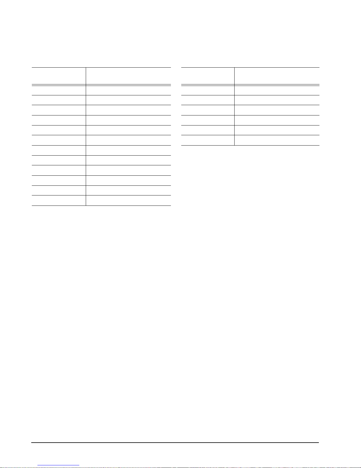
When the RC bit is on e, reall ocatio ns are d isabled even i f the AR RE or AWRE bits are one. The d rive wi ll still
perform data recovery actions within the limits defined by the Read Retry Count, Write Retry Count, and
Recovery Time Limit parameters. However, the drive does not report any unrecovered errors.
Table 5: Read and write retry count maximum recovery times
Maximum recovery time per
1
Read retry count
0 51.87 0 23.94
1 59.85 1 35.91
2 203.49 2 55.86
3 235.41 3 67.83
4 271.32 4 119.7
5 283.29 5 (default) 147.63
6 315.21
7 395.01
8 454.86
9 486.78
10 522.69
11 (default) 1,264.83
LBA (cumulative, msec)
Write retry count
Maximum recovery time per
1
LBA (cumulative, msec)
[1] Setting these retry c ounts to a val ue be low th e defa ult s etting cou ld res ult i n deg radat ion o f the unre cov-
ered error rate which may exceed the value given in this product manual. A setting of zero (0) will result in
the drive not performing error recovery.
For example, suppose the read /wr ite recov ery page has the RC bit set to 0, r ead ret ry co unt s et to 4, an d
the recovery time limit fi eld ( Mode S ense page 0 1, byt es 10 a nd 11) set to FF FF hex (max imum ). A f our
LBA Read command is a llowed to take up to 271.32 msec recove ry time fo r eac h of the four LBA s in the
command. If the reco very ti me lim it is set to 0 0 C8 hex (200 m sec dec imal) a four LB A rea d comm and is
allowed to take up to 200 msec for all err or re co very with in tha t command. The use of the Recover y Time
Limit field allows f iner granularity on control of the time spent in error reco very. The recov ery time limit
only starts counting when the dr ive is executi ng error recove ry and it resta rts on each command . There
fore, each command’s total re covery ti me is subjec t to the recov ery tim e lim it. Note : A reco very ti me li mit
of 0 will use the drive’s defa ult value of FF FF. Minimum re covery time limit is achieved by setting the
Recovery Time Limit field to 00 01.
-
7.3 SAS system errors
Information on the re porting of operational er rors or faults across the i nterface is given in the SAS Interface
Manual. The SSP Response returns information to the host about numerous kinds of errors or faults. The
Receive Diagnostic Results reports the results of diagnostic operations performed by the drive.
Status returned by the drive to the initiator is de scribed in the SAS Interfac e Manu al. Status reporting plays a
role in systems e rro r manage men t and its use in that res pect is d escribed in sectio ns wh ere the v arious com
mands are discussed.
40 Cheetah 15K.4 SAS Product Manual, Rev. B
-
Page 51

8.0 Installation
Cheetah disc drive installation is a plug- and-play pr ocess. The re are no j umpers, sw itches, o r terminator s on
the drive.
SAS drives are desi gned to be used in a host s ystem that provides a SAS -compatible backplane with ba ys
designed to accom odate the drive. In su ch systems, the h ost system typically p rovides a carrier or tray into
which you need to mount the drive. Mount the drive to the carrier or tray provided by the host system using four
6-32 UNC screws. Do not over-tighten or force the screws. You can mount the drive in any orientation.
Note. SAS drives a re designed to be attached to the host system without I/O or power cables. If you
intend the use the drive in a non-backplane host system , connecting the drive using high- quality
cables is acceptable as long as the I/O cable length does not exceed 4 meters (13.1 feet).
Slide the carrier or tray into the appropriate bay in your host system using the instructions provided by the host
system. This connects the drive directly to your system’s SAS connector. The SAS connector is normally
located on a SAS backpanel. See
Power is supplied through the SAS connector.
The drive is shipped fr om the factory low-level forma tted in 512 -byte logical blocks. You need to reformat the
drive only if you want to select a different logical block size.
Section 9.4.1 for additional information about these connectors.
SAS Interface
connector
Figure 17. Physical interface
8.1 Drive orientation
The drive may be m ounted in any orientation. All dr ive performance characterizati ons, however, have been
done with the drive in horizontal (discs level) and vertical (drive on its side) orientations, which are the two pre
ferred mounting orientations.
Cheetah 15K.4 SAS Product Manual, Rev. B 41
J6
-
Page 52

8.2 Cooling
Cabinet cooling mus t be desig ned by th e customer so tha t the ambi ent tempera ture imm ediately sur roundin g
the drive will not exceed temperature conditions specified in
The rack, cabinet, or drawer environment for the drive must provide heat remov al from the electronics and
head and disc assem bl y (HD A). You should confirm that ade quate heat removal is pr o vided us in g th e tem per
ature measurement guidelines described in Section 6.4.1.
Forced air flow may be required to keep temper atures at or below the temp eratures spe cified in Section 6.4.1
in which case the drive should be oriented, or air flow directed, so that the least amount of air flow resistance is
created while providi ng air flow to the elec tronics and HDA. Al so, the shortest poss ible path between the air
inlet and exit should be chos en to minimi ze the tr avel leng th of air heated by the drive and other heat sourc es
within the rack, cabinet, or drawer environment.
If forced air is det er min ed to be nec es sa ry, possible air-flow patter ns a re s hown i n Fi gur e 18. The air-flow patterns are created by on e or more fans, e ither forcing or d rawing air as sh own in the illu strations. C onduction,
convection, or other for ced air-flow patterns are acceptabl e as long as the temperature m easurement guide
lines of Section 6.4.1 are met.
Section 6.4.1, "Temperature."
-
-
Note. Air flows in the direction shown (back to front)
or in reverse direction (front to back)
Note. Air flows in the direction shown or
in reverse direction (side to side)
Figure 18. Air flow
Above unit
Under unit
Above unit
Under unit
42 Cheetah 15K.4 SAS Product Manual, Rev. B
Page 53

8.3 Drive mounting
Mount the drive using the bottom or side mounting holes. If you mount the drive using the bottom holes, ensure
that you do not physically distort the drive by attempting to mount it on a stiff, non-flat surface.
The allowable mounting surface stiffness is 80 lb/in (14.0 N/mm). The following equation and paragraph define
the allowable mounting surface stiffness:
K x X = F < 15lb = 67N
where K is the mounting s urface stiffness (units in lb/i n or N/mm) and X is the out-of-plane surfac e distortion
(units in inches or millimeters ). The out-of- plane distor tion (X) is determine d by defin ing a plane w ith three o f
the four mounting po ints fixed and evaluat ing the out-of-plan e deflection of the fo urth mounting poi nt when a
known force (F) is applied to the fourth point.
8.4 Grounding
Signal ground (PCB A) and HDA ground a re connected to gether in the drive an d cannot be separate d by the
user. The equipment in which the drive is mou nte d is co nne cte d dire ct ly to the HD A an d P CBA with no el ec tri
cally isolating s hock mounts. If it is desired for the sy stem chassis to not be connected t o the HDA/PCBA
ground, the systems in tegrator or user must provide a noncond uctive (elec trically is olating) m ethod of mou nt
ing the drive in the host equipment.
Increased radiated em issions may res ult if you do not provid e the maximum su rface area ground conn ection
between system ground and drive ground. This is the system designer’s and integrator’s responsibility.
-
-
Cheetah 15K.4 SAS Product Manual, Rev. B 43
Page 54

44 Cheetah 15K.4 SAS Product Manual, Rev. B
Page 55
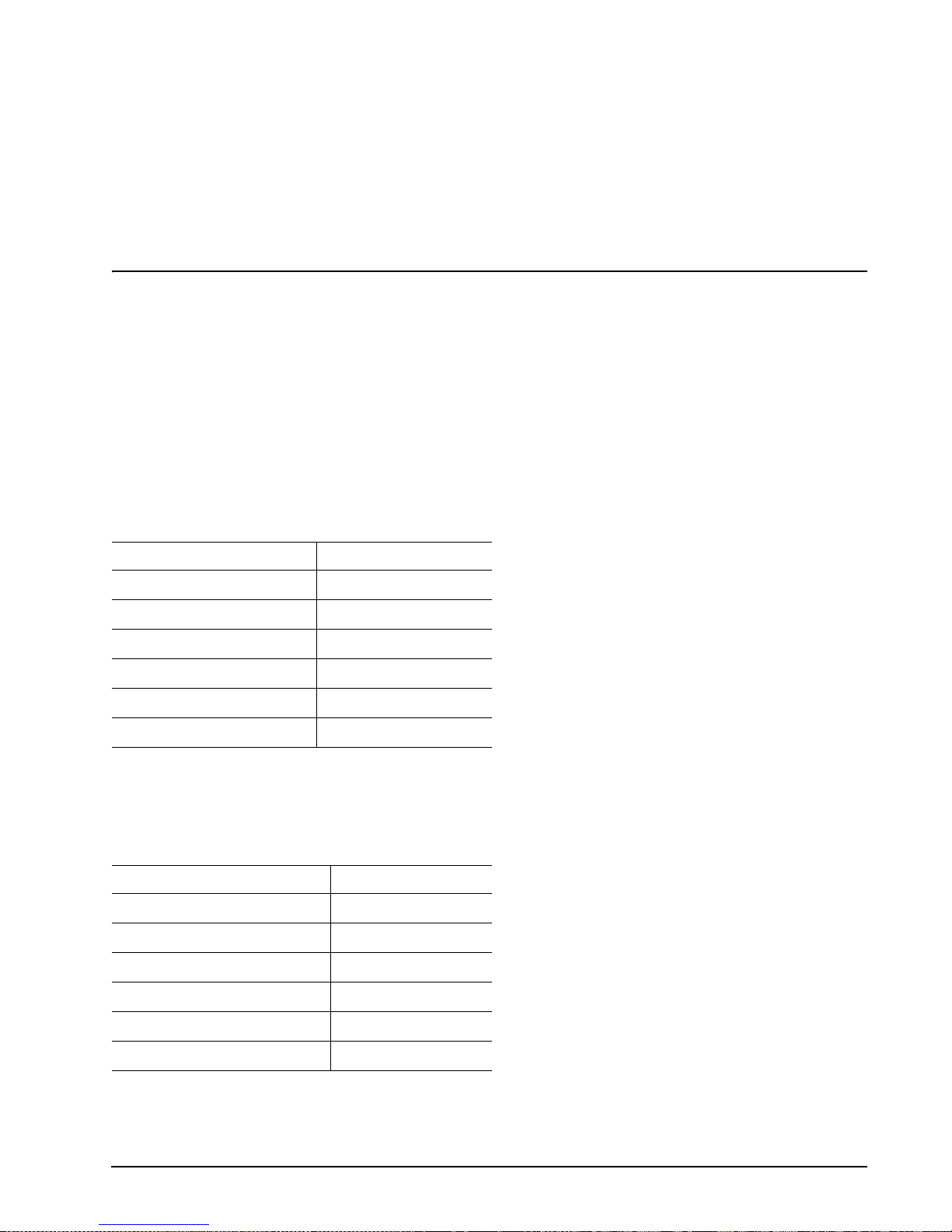
9.0 Interface requirements
This section partially describes the interface requirements as implemented on Cheetah drives. Additional information is provided in the SAS Interface Manual (part number 100293071).
9.1 SAS features
This section lists the SAS-specific features supported by Cheetah drives.
9.1.1 task management functions
Table 6 lists the SAS task management functions supported.
Table 6: SAS task management functions supported
Ta sk nam e Supported
Abort Task Yes
Clear ACA Yes
Clear task s et Yes
Abort task set Yes
Logical Unit Reset Yes
Query Task Yes
9.1.2 task management respons es
Table 7 lists the SAS response codes returned for task management functions supported.
Table 7: Task management response codes
Function name Response code
Function complete 00
Invalid frame 02
Function not supported 04
Function failed 05
Function succeeded 08
Invalid logical unit 09
Cheetah 15K.4 SAS Product Manual, Rev. B 45
Page 56

9.2 Dual port support
Cheetah SAS drives have two independent ports. These ports may be connected in the same or different SCSI
domains. Each drive port has a unique SAS address.
The two ports run at the same link ra te. The first po rt to successfu lly complet e speed ne gotiation sets the li nk
rate support by both ports. When the second port participates in sp eed negotiatio n, it indicates the only sup
ported speed is the s peed sele cted by the fi rst por t. If the fi rst port to compl ete spe ed nego tiatio n loos es sync
before the second port completes speed negotiation, both ports revert back to the power on condition of allow
ing either link rate (1.5 or 3.0 Gbits/sec).
Subject to buffer availability, the Cheetah drives support:
• Concurrent port tr ansfers—The dr ive suppor ts receiving COM MAND, TASK management transf ers on both
ports at the same time.
• Full duplex—The drive supports sending XFER_RDY, DATA and RESPONSE transfers while receiving
frames on both ports.
-
-
46 Cheetah 15K.4 SAS Product Manual, Rev. B
Page 57

9.3 SCSI commands supported
Table 8 lists the SCSI commands supported by Cheetah drives.
Table 8: Commands supported by Cheetah 15K.4 SAS family drives
Command name Command code Supported
Change Definition 40h N
Compare 39h N
Copy 18h N
Copy and Verify 3Ah N
Format Unit [1] 04h Y
DPRY bit supported N
DCRT bit supported Y
STPF bit supported Y
IP bit supported Y
DSP bit supported Y
IMMED bit supported Y
VS (vendor specific) N
Inquiry 12h Y
Date Code page (C1h) Y
Device Behavior page (C3h) Y
Firmware Numb er s page (C0h) Y
Implemented Operating Def page (81h) Y
Jumper Settings page (C2h) Y
Supported Vital Product Data page (00h) Y
Unit Serial Number page (80h) Y
Lock-unlock cache 36h N
Log Select 4Ch Y
PCR bit Y
DU bit N
DS bit Y
TSD bit Y
ETC bit N
TMC bit N
LP bit N
Log Sense 4Dh Y
Application Client Log page (0Fh) Y
Buffer Over-run/Under -run page (01h) N
Cache Statistics page (37h) Y
Factory Log page (3Eh) Y
Last n Deferred Errors or Asynchronous Events page (0Bh) N
Last n Error Events page (07h) N
Cheetah 15K.4 SAS Product Manual, Rev. B 47
Page 58

Table 8: Commands supported by Cheetah 15K.4 SAS family drives (continued)
Command name Command code Supported
Non-medium Error page (06h) Y
Pages Supported list (00h) Y
Read Error Counter page (03h) Y
Read Reverse Error Counter page (04h) N
Self-test Results page (10h) Y
Start-stop Cycle Counter page (0Eh) Y
Temperature page (0Dh) Y
Verify Error Counter page (05h) Y
Write error counter page (02h) Y
Mode Select (same pages as Mode Sense 1Ah) 15h Y [2]
Mode Select (10) (same pages as Mode Sense 1Ah) 55h Y
Mode Sense 1Ah Y [2]
Caching Parameters page (08h) Y
Control Mode page (0Ah) Y
Disconnect/Reconnect (02h) Y
Error Recover y pag e (0 1 h) Y
Format page (03h) Y
Information Exceptions Control page (1Ch) Y
Notch and Partition Page (0Ch) N
Protocol-Specific Port page (19h) Y
Power Conditi on page (1Ah ) Y
Rigid Disc Drive Geometry page (04h) Y
Unit Attention page (00h) Y
Verify Error Recovery page (07h) Y
Xor Control page (10h) N
Mode Sense (10) (same pages as Mode Sense 1Ah) 5Ah Y
Prefetch 34h N
Read 08h Y
Read Buffer (modes 0, 2, 3, Ah and Bh supported) 3Ch Y
Read Capacity 25h Y
Read Defect Data (10) 37h Y
Read Defect Data (12) B7h Y
Read Extended 28h Y
DPO bit supported Y
FUA bit supported Y
Read Long 3Eh Y
Reassign Blocks 07h Y
Receive Diagnostic Results 1Ch Y
48 Cheetah 15K.4 SAS Product Manual, Rev. B
Page 59

Table 8: Commands supported by Cheetah 15K.4 SAS family drives (continued)
Command name Command code Supported
Supported Diagnostics pages (00h) Y
Translate page (40h) Y
Release 17h Y
Release (10) 57h Y
Request Sense 03h Y
Actual Retry Count bytes Y
Extended Sense Y
Field Pointer bytes Y
Reserve 16h Y
3rd Party Reserve Y
Extent Reservation N
Reserve (10) 56h Y
3rd Party Reserve Y
Extent Reservation N
Rezero Unit 01h Y
Search Data Equal 31h N
Search Data High 30h N
Search Data Low 32h N
Seek 0Bh Y
Seek Extended 2Bh Y
Send Diagnostics 1Dh Y
Supported Diagnostics pages (00h) Y
Translate page (40h) Y
Set Limits 33h N
Start Unit/Stop Unit (spindle ceases rotating) 1Bh Y
Synchronize Cache 35h Y
Test Unit Ready 00h Y
Verify 2Fh Y
BYTCHK bit Y
Write 0Ah Y
Write and Verify 2Eh Y
DPO bit Y
Write Buffer (modes 0, 2, supported) 3Bh Y
Firmware Download option
Y
(modes 5, 7, Ah and Bh supported) [3]
Write Extended 2Ah Y
DPO bit Y
FUA bit Y
Write Long 3Fh Y
Cheetah 15K.4 SAS Product Manual, Rev. B 49
Page 60

Table 8: Commands supported by Cheetah 15K.4 SAS family drives (continued)
Command name Command code Supported
Write Same 41h Y
PBdata N
LBdata N
XDRead 52h N
XDWrite 50h N
XPWrite 51h N
[1] Cheetah drives can format to any multiple of four bytes per logical block in the range 512 to 704 bytes.
[2] Warning. Power loss during flash programming can r es ult i n fir mwa re c orr upti on . Thi s us ually m ak es th e
drive inoperable.
[3] Reference Mode Sense command 1Ah for mode pages supported.
[4] Y = Yes. Command is supported.
N = No. Command is not supported.
A = Support is available on special request.
50 Cheetah 15K.4 SAS Product Manual, Rev. B
Page 61

9.3.1 Inquiry data
Table 9 lists the Inquiry command data that the dri ve should return to the initiator per the form at given in the
SAS Interface Manual.
Table 9: Cheetah 15K.4 SAS inquiry data
Bytes Data (hex)
0-15 00 00 03** 12 8B 00 10 0A 53 45 41 47 41 54 45 20 Vendor ID
16-31 [53 54 33 37 33 34 35 34 53 53 20]120 20 20 20 20 Product ID
32-47 R# R# R# R# S# S# S# S# S# S# S# S# 00 00 00 00
48-63 00 00 00 00 00 00 00 00 00 00 00 00 00 00 00 00
64-79 00 00 00 00 00 00 00 00 00 00 00 00 00 00 00 00
80-95 00 00 00 00 00 00 00 00 00 00 00 00 00 00 00 00
96-111 00 43 6F 70 79 72 69 67 68 74 20 28 63 29 20 32* *Copyright
112-127 30* 30* 34* 20 53 65 61 67 61 74 65 20 41 6C 6C 20 notice
128-143 72 69 67 68 74 73 20 72 65 73 65 72 76 65 64 20
* Copyright year (changes with actual year).
** 02 = SCSI-2 implemented with some SCSI-3 features (default).
03 = SCSI-3 implemented.
PP 10 = Inquiry data for an Inquiry command received on Port A.
30 = Inquiry data for an Inquiry command received on Port B.
R# Four ASCII digits representing the last four digits of the product firmware release number.
S# Eight ASCII digits representing the eight digits of the product serial number.
[ ] Bytes 18 through 26 reflect model of drive. The table above shows the hex values for Model ST373454SS.
Refer to the values below for the values of bytes 18 through 27 of you particular model:
ST3146854SS 5354333134363835345353
ST373454SS 53 54 33 37 33 34 35 34 53 53 20
ST336754SS 53 54 33 33 36 37 35 34 53 53 20
9.3.2 Mode Sense data
The Mode Sense command pr ovide s a way for the driv e to report its operati ng paramete rs to the initi ator. The
drive maintains four sets of mode parameters:
1. Default values
Default values are har d-coded in the drive firmwa re stored in fl ash E-PROM (non volatile me mory) on the
drive’s PCB. These defa ult values can be changed o nly by downloadi ng a complete s et of new firmw are
into the flash E-PROM. An ini tiator can requ est and rece ive from the driv e a list of default values and use
those in a Mode Select co mmand to set up new current and s aved values , where the val ues are chan ge
able.
2. Saved values
Saved values are st ored on the dr ive’s media us ing a Mode Selec t comman d. Only parameter va lue s that
are allowed to be changed can be changed by this method. Parameters in the saved values list that are not
changeable by the Mode Select command get their values from default values storage.
When power is applied to the drive, it takes saved values from the media and stores them as current values in volatile memo ry. It is not possible to change the current val ues (or the saved va lues) with a Mode
Cheetah 15K.4 SAS Product Manual, Rev. B 51
-
Page 62

Select command before the drive achieves operating speed and is “ready.” An attempt to do so results in a
“Check Condition” status.
On drives requiring unique sa ved value s, the req uired unique saved value s are sto red into the saved va lues storage location on the medi a pr i or to sh ip ping the drive. Some drives m ay hav e uni qu e firm war e wit h
unique default values also.
On standard OEM drives, the saved values are taken from the default values list and stored into the saved
values storage location on the media prior to shipping.
3. Curr ent va lue s
Current values are volatile values being used by the drive to control its operation. A Mode Select command
can be used to change the values identifi ed as chan geable va lues. Ori ginally, current values a re installed
from saved or default values after a power on reset, hard reset, or Bus Device Reset message.
4. Changeable values
Changeable values form a bit mask, stored in nonvolatile memory, that dictates which of the current values
and saved values can be changed by a Mode Select command. A one (1) i ndicates the value can be
changed. A zero (0) indicates the value is not changeable. For example, in Table
9.3.2.1, refer to Mode
page 81, in the row entitled “CHG.” These are hex numbers representing the ch angeable v alues for Mode
page 81. Note in colu mns 5 and 6 (by tes 0 4 and 05), ther e is 00h which in dicat es tha t in byte s 04 an d 05
none of the bits are changeable. Note al so that bytes 06, 07, 09, 10, and 11 are not changeable, because
those fields are all zeros. In byte 02, hex value FF equates to the binary pattern 11111111. If there is a zero
in any bit position i n the fi eld, it mea ns that bi t is no t chan geable . Sinc e all of th e bits in byte 02 are o nes,
all of these bits are changeable.
The changeable values list can only be changed by downloading new firmware into the flash E-PROM.
Note. Because there are often several different versions of drive control firmware in the total population of
drives in the field, the Mode Sense values given in the following tables may not exactly match those
of some drives.
The following tables list the values of the data bytes returned by the drive in response to the Mode Sense command pages for SCSI implementation (see the SAS Interface Manual ).
Definitions:
DEF = Default value. Standard OEM drives are shipped configured this way.
CHG = Changeable bits; indicates if default value is changeable.
52 Cheetah 15K.4 SAS Product Manual, Rev. B
Page 63

9.3.2.1 ST3146854SS Mode Sense data
DEF Page 0(0x00), 00 00 0F 00 00 00
CHG Page 0(0x00), B7 40 0F 00 00 00
DEF Page 1(0x01), C0 0B FF 00 00 00 05 00 FF FF
CHG Page 1(0x01), FF FF 00 00 00 00 FF 00 FF FF
DEF Page 2(0x02), 00 00 00 00 00 00 00 00 00 A1 00 00 00 00
CHG Page 2(0x02), 00 00 00 00 00 00 00 00 FF FF 00 00 00 00
DEF Page 3(0x03), 56 20 00 00 00 30 00 00 02 C2 02 00 00 01 00 AA 00 91 40 00 00 00
CHG Page 3(0x03), 00 00 00 00 00 00 00 00 00 00 00 00 00 00 00 00 00 00 00 00 00 00
DEF Page 4(0x04), 00 C6 88 08 00 00 00 00 00 00 00 00 00 00 00 00 00 00 3A A7 00 00
CHG Page 4(0x04), 00 00 00 00 00 00 00 00 00 00 00 00 00 00 00 00 00 00 00 00 00 00
DEF Page 7(0x07), 00 0B FF 00 00 00 00 00 FF FF
CHG Page 7(0x07), 0F FF 00 00 00 00 00 00 FF FF
DEF Page 8(0x08), 14 00 FF FF 00 00 FF FF FF FF 80 20 00 00 00 00 00 00
CHG Page 8(0x08), B5 00 00 00 FF FF FF FF 00 00 A0 FF 00 00 00 00 00 00
DEF Page 10(0x0A), 02 00 00 00 00 00 00 00 08 4D
CHG Page 10(0x0A), 03 F1 00 00 00 00 00 00 00 00
DEF Page 25(0x19), 06 00 07 D0 00 00
CHG Page 25(0x19), 10 00 FF FF FF FF
DEF Page 26(0x1A), 00 02 00 00 00 05 00 00 00 04
CHG Page 26(0x1A), 00 03 FF FF FF FF 00 00 00 00
DEF Page 28(0x1C), 10 00 00 00 00 00 00 00 00 01
CHG Page 28(0x1C), 9D 0F FF FF FF FF FF FF FF FF
DEF Page 53(0x35), 01 00 00 00 01 00 00 0F 00 00
CHG Page 53(0x35), 03 00 00 00 03 00 FF FF 00 00
DEF Page 57(0x39), 00 0C 00 00 00 00 00 00 00 00
CHG Page 57(0x39), 00 0C 00 00 00 00 00 00 00 00
DEF Page 58(0x3A), 00 00 00 18 00 18 50 00 00 00
CHG Page 58(0x3A), 00 00 FF FF FF FF 00 00 00 00
Cheetah 15K.4 SAS Product Manual, Rev. B 53
Page 64

9.3.2.2 ST373454SS Mode Sense data
DEF Page 0(0x00), 00 00 0F 00 00 00
CHG Page 0(0x00), B7 40 0F 00 00 00
DEF Page 1(0x01), C0 0B FF 00 00 00 05 00 FF FF
CHG Page 1(0x01), FF FF 00 00 00 00 FF 00 FF FF
DEF Page 2(0x02), 00 00 00 00 00 00 00 00 00 A1 00 00 00 00
CHG Page 2(0x02), 00 00 00 00 00 00 00 00 FF FF 00 00 00 00
DEF Page 3(0x03), 2B 10 00 00 00 18 00 00 02 C2 02 00 00 01 00 AA 00 91 40 00 00 00
CHG Page 3(0x03), 00 00 00 00 00 00 00 00 00 00 00 00 00 00 00 00 00 00 00 00 00 00
DEF Page 4(0x04), 00 C6 88 04 00 00 00 00 00 00 00 00 00 00 00 00 00 00 3A A7 00 00
CHG Page 4(0x04), 00 00 00 00 00 00 00 00 00 00 00 00 00 00 00 00 00 00 00 00 00 00
DEF Page 7(0x07), 00 0B FF 00 00 00 00 00 FF FF
CHG Page 7(0x07), 0F FF 00 00 00 00 00 00 FF FF
DEF Page 8(0x08), 14 00 FF FF 00 00 FF FF FF FF 80 20 00 00 00 00 00 00
CHG Page 8(0x08), B5 00 00 00 FF FF FF FF 00 00 A0 FF 00 00 00 00 00 00
DEF Page 10(0x0A), 02 00 00 00 00 00 00 00 04 7E
CHG Page 10(0x0A), 03 F1 00 00 00 00 00 00 00 00
DEF Page 25(0x19), 06 00 07 D0 00 00
CHG Page 25(0x19), 10 00 FF FF FF FF
DEF Page 26(0x1A), 00 02 00 00 00 05 00 00 00 04
CHG Page 26(0x1A), 00 03 FF FF FF FF 00 00 00 00
DEF Page 28(0x1C), 10 00 00 00 00 00 00 00 00 01
CHG Page 28(0x1C), 9D 0F FF FF FF FF FF FF FF FF
DEF Page 53(0x35), 01 00 00 00 01 00 00 0F 00 00
CHG Page 53(0x35), 03 00 00 00 03 00 FF FF 00 00
DEF Page 57(0x39), 00 0C 00 00 00 00 00 00 00 00
CHG Page 57(0x39), 00 0C 00 00 00 00 00 00 00 00
DEF Page 58(0x3A), 00 00 00 18 00 18 50 00 00 00
CHG Page 58(0x3A), 00 00 FF FF FF FF 00 00 00 00
54 Cheetah 15K.4 SAS Product Manual, Rev. B
Page 65

9.3.2.3 ST336754SS Mode Sense data
DEF Page 0(0x00), 00 00 0F 00 00 00
CHG Page 0(0x00), B7 40 0F 00 00 00
DEF Page 1(0x01), C0 0B FF 00 00 00 05 00 FF FF
CHG Page 1(0x01), FF FF 00 00 00 00 FF 00 FF FF
DEF Page 2(0x02), 00 00 00 00 00 00 00 00 00 A1 00 00 00 00
CHG Page 2(0x02), 00 00 00 00 00 00 00 00 FF FF 00 00 00 00
DEF Page 3(0x03), 15 88 00 00 00 0C 00 00 02 C2 02 00 00 01 00 F0 00 91 40 00 00 00
CHG Page 3(0x03), 00 00 00 00 00 00 00 00 00 00 00 00 00 00 00 00 00 00 00 00 00 00
DEF Page 4(0x04), 00 C6 88 02 00 00 00 00 00 00 00 00 00 00 00 00 00 00 3A A7 00 00
CHG Page 4(0x04), 00 00 00 00 00 00 00 00 00 00 00 00 00 00 00 00 00 00 00 00 00 00
DEF Page 7(0x07), 00 0B FF 00 00 00 00 00 FF FF
CHG Page 7(0x07), 0F FF 00 00 00 00 00 00 FF FF
DEF Page 8(0x08), 14 00 FF FF 00 00 FF FF FF FF 80 20 00 00 00 00 00 00
CHG Page 8(0x08), B5 00 00 00 FF FF FF FF 00 00 A0 FF 00 00 00 00 00 00
DEF Page 10(0x0A), 02 00 00 00 00 00 00 00 02 5B
CHG Page 10(0x0A), 03 F1 00 00 00 00 00 00 00 00
DEF Page 25(0x19), 06 00 07 D0 00 00
CHG Page 25(0x19), 10 00 FF FF FF FF
DEF Page 26(0x1A), 00 02 00 00 00 05 00 00 00 04
CHG Page 26(0x1A), 00 03 FF FF FF FF 00 00 00 00
DEF Page 28(0x1C), 10 00 00 00 00 00 00 00 00 01
CHG Page 28(0x1C), 9D 0F FF FF FF FF FF FF FF FF
DEF Page 53(0x35), 01 00 00 00 01 00 00 0F 00 00
CHG Page 53(0x35), 03 00 00 00 03 00 FF FF 00 00
DEF Page 57(0x39), 00 0C 00 00 00 00 00 00 00 00
CHG Page 57(0x39), 00 0C 00 00 00 00 00 00 00 00
DEF Page 58(0x3A), 00 00 00 18 00 18 50 00 00 00
CHG Page 58(0x3A), 00 00 FF FF FF FF 00 00 00 00
Cheetah 15K.4 SAS Product Manual, Rev. B 55
Page 66

9.4 Miscellaneous operating features and conditions
Table 10 lists variou s features and con dit ions. A “Y” in the support c olumn i ndica tes the fea ture or co nditio n is
supported. An “N” in the support column indicates the feature or condition is not supported.
Table 10: Miscellaneous features
Supported Feature or condition
N Automatic contingent allegiance
N Asynchronous event notification
N Synchronized (locked) spind le ope rati on
Y Segmented caching
N Zero latency read
Y Queue tagging (up to 64 queue tags supported)
Y Deferred error handling
Y Parameter rounding (controlled by Round bit in Mode Select page 0)
Y Reporting actual retry count in Extended Sense bytes 15, 16, and 17
N Adaptive caching
Y SMP = 1 in Mode Select command needed to save RPL and rotational offset bytes
Table 11: Miscellaneous status
Supported Status
Y Good
Y Check condition
Y Condition met/good
Y Busy
Y Intermediate/good
Y Intermediate/condition met/good
Y Reservation conflict
Y Task set full
N ACA active
N ACA active, faulted initiator
56 Cheetah 15K.4 SAS Product Manual, Rev. B
Page 67

9.4.1 SAS physical interface
Figure 19 shows the location of the SAS device connector J1. Figures 20 and 21 provide the dimensions of the
SAS device.
Details of the physical, el ectrical, and logica l characteristics are p rovided within this se ction. The operati onal
aspects of Seagate’s SAS drives are provided in the SAS Interface Manual..
J6
SAS Interface
connector
Figure 19. Physical interface
Cheetah 15K.4 SAS Product Manual, Rev. B 57
Page 68

0.80 (6X)
0.30 0.05 (2X)
4.00 0.08
0.15 D
2.00 (3X)
7.625.92
5.08
42.73 REF.
41.13 0.15
0.20 B
C
A
4.65
0.52 0.08 x 45
0.45 0.03 (7X)
0.10 M E
B
1.10
C OF DATUM D
L
0.30 0.05 (4X)
0.35MIN
B
C
15.875
1.27 (14X)
P15
Figure 20. SAS connector dimensions
33.43 0.05
5.08
C OF DATUM B
L
A
15.875
1.27 (6X)
P1
R0.30 0.08 (4X)
SEE Detail1
B
0.84 0.05 (22X)
0.15 B
4.90 0.08
S1
S7
58 Cheetah 15K.4 SAS Product Manual, Rev. B
Page 69

Detail A
SEE Detail 2
3.90 0.15
2.25 0.05
4.85 0.05
0.10 B
E
SECTION A - A
0.08 0.05
S14
6.10
4.40 0.15
0.35 0.05
CONTACT SURFACE FLUSH
TO DATUM A 0.03
S8
0.40 0.05 X 45 (3X)
CORING ALLOWED
IN THIS AREA.
A
0.30 0.05 x 45 (5X)
R0.30 0.08
45
SECTION C - C
C
1.95 0.08
1.23 0.05
65
30
Detail 2
0.08 0.05
2.40 0.08
0.10 A
SECTION B - B
D
1.90 0.08
Figure 21. SAS connector dimensions
9.4.2 Physical characteristics
This section defines physical interface connector.
9.4.3 Connector requirements
Contact your preferred conn ector manu facturer for mating part in formation . Part numb ers for SAS connectors
will be provided in a fu ture rev ision of th is pub lica tion when produ ction parts are availabl e from maj or co nnec
tor manufacturers.
The SAS device connector is illustrated i n Figures 20 and 21.
-
Cheetah 15K.4 SAS Product Manual, Rev. B 59
Page 70

9.4.4 Electrical description
SAS drives use the device connector for:
• DC power
• SAS interface
• Activity LED
This connector is designed to either plug directly into a backpanel or accept cables.
9.4.5 Pin descriptions
This section provides a pin-out of the SAS device and a description of the functions provided by the pins.
Table 12: SAS pin descriptions
Pin Signal name Signal type Pin Signa l name Signal type
S1 Port A Ground P1* NC (reserved 3.3Volts)
S2* +Port A_in Diff. input pa ir P2* NC (reserved 3.3Volts)
S3* -Port A_in P3 NC (reserved 3.3Volts)
S4 Port A Ground P4 Ground
S5* -Port A_out Diff output pair P5 Ground
S6* +Port A_out P6 Ground
S7 Port A Ground P7 5 Volts charge
S8 Port B Ground P8* 5 Volts
S9* +Port B_in Diff. input pa ir P9* 5 Volts
S10* -Port B_in P10 Ground
S11 Port A Ground P11* Ready LED Open collector out
S12* -Port B_out Diff output pair P12 Ground
S13* +Port B_out P13 12 Volts charge
S14 Port B Ground P14* 12 Volts
P15* 12 Volts
* - Short pin to support hot plugging
NC - No connection in the drive.
60 Cheetah 15K.4 SAS Product Manual, Rev. B
Page 71

9.4.6 SAS transmitters and receivers
A typical SAS differential copper tran smitt er and recei ver pair is sho wn in Fig ure 22. The receiver i s AC coupling to eliminate ground shift noise.
TX
Transmitter
TY
Figure 22. SAS transmitters and receivers
Differential
Transfer Medium
.01
.01
RX
Receiver
100100
RY
9.4.7 Power
The drive receives power (+5 volts and +12 volts) through the SAS device connector.
Three +12 volt pi ns provide power to the drive, 2 shor t and 1 long. The c urrent return for the +12 volt power
supply is through the common ground pins. The supply current and return current must be distributed as
evenly as possible among the pins.
Three +5 volt pins provide power to the drive, 2 short a nd 1 lo ng. The current return for the +5 volt power s upply is through the common ground pins. The supply current and return current must be distributed as evenly as
possible among the pins.
Current to the drive throu gh the long po wer pins may be l imited by the s ystem to red uce inrush current to th e
drive during hot plugging.
9.5 Signal characteristics
This section descri bes the elec tric al si gna l c harac te ri st ic s of the dr iv e’s input a nd output signals. See Ta ble 12
for signal type and signal name information.
9.5.1 Ready LED Out
The Ready LED Out signal is driven by the drive as indicated in Table 13.
Table 13: Ready LED Out conditions
Normal command activity LED status
Ready LED Meaning bit mode page 19h
Spun down and no activity Off Off
Spun down and activity (command executing) On On
Spun up and no activity On Off
Spun up and activity (command executing) Off On
Spinning up or down Blinks steadily
(50% on and 50% off, 0.5 seconds on and off for 0.5 seconds)
Format in progress, each cylinder change Toggles on/off
0 1
Cheetah 15K.4 SAS Product Manual, Rev. B 61
Page 72

The Ready LED Out signal i s designed to pull down the cathode of an LED. T he anode is attached to the
proper +3.3 volt supply through an appropr i ate cu rren t li mi tin g r esis tor. The LED and the current limiting resi s
tor are external to the drive. See Table 14 for the output characteristics of the LED drive signals.
Table 14: LED drive signal
State Test condition Output voltage
LED off, high 0 V ≤ VOH ≤ 3.6 V -100 µA < IOH < 100 µA
LED o
n, l
ow IOL = 15 mA 0 ≤ VOL ≤ 0.225 V
9.5.2 Differential signals
The drive SAS differential signals comply with the intra-enclosure (internal connector) requirements of the SAS
standard.
Table 15 defines the general interface characteristics.
Table 15: General interface characteristics
Characteristic Units 1.5 Gbps 3.0 Gbps
Bit rate (nominal) Mbaud 1,500 3,000
Unit interval (UI)(nominal) ps 666.6 333.3
Impedance (nominal, differential ) ohm 100 100
Transmitter transients, maximum V ± 1.2 ± 1.2
Receiver transients, maximum V ± 1.2 ± 1.2
-
9.5.2.1 Eye masks
9.5.2.1.1 Eye masks overview
The eye masks are g raphical representations of t he voltage and time limits on the s ignal at the compliance
point. The time value s b etwe en X 1 a nd (1 - X 1) c ov er al l bu t 10
-12
of the jitter populati on. T he ran dom content
of the total jitter population has a range of ± 7 standard deviations.
62 Cheetah 15K.4 SAS Product Manual, Rev. B
Page 73

9.5.2.1.2 Receive eye mask
Figure 23 describes the r eceive eye mas k. This eye mask appli es to j itter after the applicati on of a s ingle pole
high-pass frequency-weigh t in g fun ction that p ro gr essi vely att enu ates ji tte r a t 20 d B/d ecade b el ow a fr eq uen cy
of ((bit rate) / 1.667).
Absolute
amplitude
(in V)
Z2
Z1
0 V
-Z1
-Z2
01
X1X2
N ormalized time (in U I)
Figure 23. Receive eye mask
1-X1
1-X2
Verifying compliance with the limits represented by the receive eye mask should be done with reverse channel
traffic present in order that the effects of crosstalk are taken into account.
9.5.2.1.3 Jitter toleran c e masks
Figure 24 describes the recei ve tole rance eye masks a nd is con structed u sing the X2 and Z2 values given i n
table 18. X1OP is half the value for total jitter intable 18 and X1
is half the value for total jitter in table 19, for
TOL
jitter frequencies above ((bit rate) / 1.667).
Absolute
amplitude
(in V)
Z2
Z1
OP
Z1
TOL
0 V
-Z1
TOL
-Z1
OP
-Z2
X1
01
OP
X1
TOL
Normalized ti me (in UI)
(additional sinusoidal jitter) / 2
X2
1-X1
1-X1
OP
TOL
Outline of eye mask
before adding
sinusoidal jitter
Outline of eye mask
after adding
sinusoidal jitter
Figure 24. Reveive tolerance eye mask
Cheetah 15K.4 SAS Product Manual, Rev. B 63
Page 74

The leading and tr ailing edge slopes of figure 23 shall be pres erved. As a result the ampli tude value of Z1 is
less than that giv en in table 1 7 a nd Z1
and Z1OP shall be defined fr om thos e sl ope s by the following equa-
TOL
tion:
Z1
TOL
Z1OPx
X2
---------------------------------------------------------------------------------------------------------------------------------- -=
OP
05,()xadditional sinusoidal jitter()– X1
X2
OP
X1
–
OP
–
OP
where:
Z1
is the value for Z1 to be used for the tolerance masks; and
TOL
Z1OP, X1OP, and X2OP are the values in table 17 for Z1, X1, and X2.
The X1 points in the recei ve toleran ce mask s are gr eater than the X1 points in t he rece ive mask s, due to the
addition of sinusoidal jitter.
Figure 25 defines the sinusoidal jitter mask.
Pe ak-to-
peak
sinusoidal
jitter
(in UI)
1.5
1.0
Si nusoidal j i tter frequency
(log/log plot)
= 1.5 x 10⁹ for 1.5 Gbps
F
NOM
F
= 3.0 x 10⁹ for 3.0 Gbps
NOM
0.1
0
F
/ 25,000 F
NOM
Frequency (in kHz)
Figure 25. Sinusoidal jitter mask
NOM
/ 1,667
64 Cheetah 15K.4 SAS Product Manual, Rev. B
Page 75

9.5.2.2 Transmitter signal characteristics
Table 16 specifies the signal requirem ents at the transmitter end of a TxRx con nection as measur ed into the
zero-length test load. All specifications are based on differential measurements.
The OOB sequence is per formed at si gnal voltage le vels corr esponding to th e lowest supported tran sfer rate.
Table 16 specifies the signal characteristics.
T able 16: Transmitter signal characteristics
Signal characteristic
b
Skew
Tx Off Voltage
Maximum rise/fall time
Minimum ri se/fall time
Maximum transmitter output imbalance
OOB offset delta
OOB common mode delta
a All tests in this table shall be performed with zero-length test load shown in figure 27.
b The skew measurement shall be made at the mid point of the tran sition wi th a repeating 01 01b patte rn on the physic al
link. The same stable trigger, coherent to the data stream, shall be used for both the Tx+ and Tx- signals. Skew is
defined as the time difference between the m ean s of th e m idpoint crossing times of the Tx+ signal and the Tx- signa l.
c The transmitter off voltage is the maximum A.C. voltage measured at compliance points when the transmitter is
unpowered or transmitting D.C. idle (e.g., during idle time of an OOB signal).
d Rise/fall times are measured from 20 % to 80 % of the transition with a repeating 0101b pattern on the physical link.
e The maximum difference between the V+ and V- A.C. RMS transmitter amplitudes measured on a CJTPAT test
pattern (see 9.5.2.3.3) into the test load shown in figure 27, as a percentage of the average of the V+ and V- A.C.
RMS amplitudes.
f The maximum diff eren ce in the average differential vol t ag e (D .C. offset) component between the burs t tim es and the
idle times of an OOB signal.
g The maximum difference in the average of the common mode voltage between the burst times and the idle times of
an OOB signal.
a
Units 1.5 Gbps 3.0 Gbps
ps 20 15
c
d
d
e
f
g
mV(P-P) < 50 < 50
ps 273 137
ps 67 67
% 10 10
mV ± 25 ± 25
mV ± 50 ± 50
Cheetah 15K.4 SAS Product Manual, Rev. B 65
Page 76

9.5.2.3 Receiver signal characteristics
Table 17 defines the complia nce point requ irements of the signal at the recei ver end of a TxRx connection as
measured into the test loads specified in figure 26 and figure 27.
Table 17: Receiver sign al characteristics
Signal characteristic Units 1.5 Gbps 3.0 Gbps
Jitter (see figure 23)
b
N/A See table 18 See table 18
2 x Z2 mV(P-P) 1,200 1,600
2 x Z1 mV(P-P) 325 275
a
X1
UI 0.275 0.275
X2 UI 0.50 0.50
d
Skew
ps 80 75
Max voltage (non-op) mV(P-P) 2.000 2.000
Minimum OOB ALIGN burst amplitude
Maximum noise during OOB idle time
Max near-end crosstalk
a The value for X1 shall be half the va lue given for total jitte r in table 18. The test or an aly si s sh all include the effect s o f
a single pole high-pass frequency-weighting function that progressively attenuates jitter at 20 dB/decade below a
frequency of ((bit rate) / 1,667).
b The value for X1 applies at a total jitter probability of 10
between the mask and actual signals is not a valid method for determining compliance with the jitter output
requirements.
c With a measurement bandwidth of 1.5 times the baud rate (i.e. 4.5 GHz for 3.0 Gbps).
d The skew measurement shall be made at the mid point of the trans ition with a repe ating 0101b p attern on the physical
link. The same stable trigger, coherent to the data stream, shall be used for both the Rx+ and Rx- signals. Skew is
defined as the tim e dif feren ce between t he mea ns of th e mid poi nt cros sing t imes of the R x+ si gnal a nd the R x- si gnal.
e Near-end crosstalk is the unwan t ed s ign al am pli tud e a t rec ei ve r term in al s D R, C R, an d XR c ou ple d from signals and
noise sources other than the desired signal. Refer to SFF-8410.
e
c
c
mV(P-P) 240 240
mV(P-P) 120 120
mV(P-P) 100 100
-12
. At this level of probability direct visual comparison
9.5.2.3.1 Jitter
Table 18 defines the maximum allowable jitter .
Table 18: Maximum allowable jitter
1.5 Gbps m,
Deterministic jitter
0.35 0.55 0.35 0.55
a Units are in UI.
b The values for jitter in this section are measured at the average amplitude point.
c Total jitter is the sum of dete rmi nis tic ji tter a nd ran do m ji tter. If the actual dete rmi ni sti c ji tter i s le ss tha n the maxim um
specified, then the ran dom jitt er may increase as long as the total ji tter does not ex ce ed th e specified maximum total
jitter.
d Total jitter is specified at a probability of 10
e The deterministic and total values in this table apply to jitter after application of a single pole high-pass frequency-
weighting function that progressively attenuates jitter at 20 dB/decade below a frequency of ((bit rate) / 1 667).
f If total jitter received at any point is less th an the maximum allowed, the n the jitter dis tribution of th e signals is allowed
to be asymmetric. The total jitter plus the magnitude of the asymmetry shall not exceed the allowed maximum total
jitter. The numerical difference between the average of the peaks with a BER < 10
individual events is the measure of the asymmetry. Jitter peak-to-peak measured < (maximum total jitter -
|Asymmetry|).
q
n
Total jitterc,d,e,f Deterministic jittere Total jitterc,d,e,f
-12
.
3.0 Gbps m,
-12
n
and the average of the
66 Cheetah 15K.4 SAS Product Manual, Rev. B
Page 77

9.5.2.3.2 Receiver jitter tolerance
Table 19 defines the amount of jitter the receiver shall tolerate .
Table 19: Receiver jitter tolerance
jitter
e,f,h
a
Total
jitter
h
Sinusoidal
b,d
jitter
-12
. Receivers shall tolerate sinusoidal jitter of
-12
. The additional 0.1 UI of sinusoidal jitter is
3.0 Gbps
Deterministic
1.5 Gbps
Sinusoidal
b,c
jitter
0.10 0.35 0.65 0.10 0.35 0.65
a Units are in UI.
b The jitter values given are normative for a combination of deterministic jitter, random jitter, and sinusoidal jitter that
receivers shall be able to tolerate without exceeding a BER of 10
progressively greater amplitude at lower frequencies, according to the mask in figure 25 with the same deterministic
jitter and random jitter levels as were used in the high frequency sweep.
c Sinusoidal swept frequency: 900 kHz to > 5 MHz.
d Sinusoidal swept frequency: 1.800 kHz to > 5 MHz.
e No value is given for random jitter. For compliance with this standard, the actual random jitter amplitude shall be the
value that brings total jitter to the stated value at a probability of 10
added to ensure the receiver has sufficient operating margin in the presence of external interference.
f Deterministic jitter: 900 kHz to 750 MHz.
g Deterministic jitter: 1.800 kHz to 1.500 MHz.
h The deterministic and total values in this table apply to jitter after application of a single pole high-pass frequency-
weighting function that progressively attenuates jitter at 20 dB/decade below a frequency of ((bit rate) / 1.667).
Deterministic
jitter
e,g,h
a
Total
h
jitter
9.5.2.3.3 Compliant jitter test pattern (CJTPAT)
The CJTPAT within a compliant pro tocol frame is used f or all jitte r testing unl ess othe rwise spec ified. Se e the
SAS Interface Manual for def inition of the requ ired pattern on the phys ical link and information re garding spe
cial considerations for scrambling and running disparity.
-
9.5.2.3.4 Impedance specifications
Table 20 defines impedance requirements.
Table 20: Impedance requirements (Sheet 1 of 2)
Requirement Units 1.5 Gbps 3.0 Gbps
Time domain reflectometer rise time 20 % to 80 %
a,b
ps 100 50
Media (PCB or cable)
Differential impedance
Differential impedance imbalance
Common mode impedance
b,c,d
b,c,d
b,c,d,g
ohm 100 ± 10 100 ± 10
ohm 5 5
ohm 32.5 ± 7.5 32.5 ± 7.5
Mated connectors
Differential impedance
Differential impedance imbalance
Common mode impedance
b,c,d
b,c,d
b,c,d,g
ohm 100 ± 15 100 ± 15
ohm 5 5
ohm 32.5 ± 7.5 32.5 ± 7.5
Receiver termination
Differential impedance
Differential impedance imbalance
Receiver termination time constant
b,e,f
b,e,f,g
b,e,f
ohm 100 ± 15 100 ± 15
ohm 5 5
ps 150 max 100 max
Cheetah 15K.4 SAS Product Manual, Rev. B 67
Page 78

Table 20: Impedance requirements (Sheet 2 of 2)
receiver termination time constant
Requirement Un its 1.5 Gbps 3.0 Gbps
Common mode impedance
b,e
ohm 20 min/40 max 20 min/40 max
Transmitter source termination
Differential impedance
Differential impedance imbalance
Common mode impedance
a All times indicated for time domain reflectometer measurements are recorded times. Recorded times are twice the
transit time of the time domain reflectometer signal.
b All measurements are made through mated connector pairs.
c The media impedance measurement identifies the impedance mismatches present in the media when terminated in
its characteristic impedance. This measurement excludes mated connectors at both ends of the media, when
present, but includ es any interm ediate con nectors or s plices. The mated conn ectors me asurement ap plies onl y to the
mated connector pair at each end, as applicable.
d Where the media has an electrical length of > 4 ns the procedure detailed in SFF-8410, or an equivalent procedure,
shall be used to determine the impedance.
e The receiver termination impedance specification applies to all receivers in a TxRx connection and covers all time
points between the connector nearest the receiver, the receiver, and the transmission line terminator. This
measurement shall be made from that connector.
f At the time point corresponding to th e con ne cti on of the rec eiv er to th e trans m is sio n li ne the inpu t ca p ac it a nc e of the
receiver and its connection to the transmission line may cause the measured impedance to fall below the minimum
impedances specified in this table. The area of the impedance dip (amplitude as ρ, the reflection coefficient, and
duration in time) caused by this capacitance is the receiver termination time constant. The receiver time constant
shall not be greater than the values shown in this table. An approximate value for the receiver termination time
constant is giv en b y t he p r od uct of the amplitude of the dip (as ρ) and its width (in p s) measured at the half amplitude
point. The ampli tude i s de fined as be ing th e dif fere nce i n the refl ection coef fic ient between the re flecti on co ef ficien t at
the nominal impedance and the reflection coefficient at the minimum impedance point. The value of the receiver
excess input capacitance is given by the following equation:
b
b,g
b
ohm 60 min/115 max 60 min/115 max
ohm 5 5
ohm 15 min/40 max 15 min/40 max
C
--------------------------------------------------------------------------------- -=
||
R0 RR
()
where (R0 || RR) is the parallel combination of the transmission line characteristic impedance and
termination resistance at the receiver.
g The difference in measured im pe dan ce to g round on the plus and minus term in als on the in terc on nec t, t r ans mi tte r or
receiver, with a differential test signal applied to those terminals.
9.5.2.4 Electrical TxRx connections
TxRx connections may be divided into TxRx connection segments. In a single TxRx connection individual
TxRx connection segme nts may be for med from di fferin g me dia and m ate ri al s, inc lu din g tr aces on p ri nte d wir
ing boards and optic al fiber s. This su bclause ap plies onl y to TxRx co nnection segments that are form ed from
electrically conducti ve media .
Each electrical TxRx co nnection segment shall comply with the impedance requirements of table 20 for the
media from which they are formed. An equalizer network, if present, shall be part of the TxRx connection.
TxRx connections that are composed entirely of electrically conducting media shall be applied only to homogenous ground applicati ons (e.g., betwe en devi ces withi n an encl osur e or rack, or between enclo sures in tercon nected by a common ground return or ground plane).
9.5.2.4.1 Transmitter characteristics
The drive are D.C. coupled.
-
68 Cheetah 15K.4 SAS Product Manual, Rev. B
Page 79

A combination of a zero-length test load and the transmitter compliance transfer function (TCTF) test load
2
6–
05
10–
20–
6–
05
10–
20–
methodology is us ed for the spe cification of transmitte r characterist ics. This m ethodology spe cifies the trans
mitter signal at the tes t points on the requir ed test loads. The tra nsmitter uses the same settings (e.g., preemphasis, voltage swing ) with both the ze ro -len gth te st load and the TCTF tes t l oad . T he si gnal s pecifications
at IR are met under each of these loading conditions.
The TCTF is the mathematical statement of the transfer function through which the transmitter shall be capable
of producing acce ptable signals as defined by a recei ve mask. The tra nsmission magnitud e response of th e
TCTF in dB is given by the following equation for 1.5 Gbps:
1
for 50 MHz < f < 1.5 GHz, and:
20–log10e() 65, 10
,
f
××()20, 10
f××()33, 10
f2××()++()× dB×=
-
S
21
for 1.5 GHz < f < 5.0 GHz,
where:
a) f is the signal frequency in hertz.
The transmission magnitude response of the TCTF in dB is given by the following equation for 3.0 Gbps:
21
for 50 MHz < f < 3.0 GHz, and:
S
21
for 3.0 GHz < f < 5.0 GHz,
where:
a) f is the signal frequency in hertz.
The TCTF is used to specify the requirements on transmitters that may or may not incorporate pre-emphasis or
other forms of compensation. A compliance interconnect is any physical interconnect with loss equal to or
greater than that of the T CT F at the abo ve frequencies that also mee ts th e ISI loss requirements shown i n
ure 28 and figure 29.
Compliance with the TC TF te st l oa d r equ ireme n t is v eri fie d by me asu r ing the s i gna l pr od uced by the transmitter through a physical compliance interconnect attached to the transmitter.
Compliance with the zero-l ength test load requirement verified by measurement made acr oss a load equivalent to the zero-length load shown in figure 27.
5 437,–dB=
20–log10e() 65, 10
10 884,–dB=
,
f
××()20, 10
f××()33, 10
f2××()++()× dB×=
fig-
For both test load cases , the tr ansmitter deli vers the output v oltages an d timing li sted i n table 17 at the designated compliance points. The default mask is IR for intra-cabinet TxRx connections. The eye masks are shown
in
9.5.2.1.
Cheetah 15K.4 SAS Product Manual, Rev. B 69
Page 80

Figure 26 shows the compliance interconnect test load.
Tx +
10 nF 5 0 ohm
10 nF
Probe
points
50 ohm
TCTF
Tx -
SAS internal connector
Figure 26. Compliance interconn ect test load
Figure 27 shows the zero-length test load.
Tx +
Tx -
10 nF
10 nF
50 ohm
P robe
points
50 ohm
SAS internal connector
Figure 27. Zero-length test load
Figure 28 shows an ISI loss example at 3.0 Gbps.
(dB)
S
21
Compliance interconnect magnitude response and
0
ISI loss
> 3.9 dB
0.9 dB
0.3
Figure 28. ISI loss example at 3.0 Gbps
ISI loss example for 3.0 Gbps
Sample complia nce in terconnect
3.01.5
Frequency (GH z)
70 Cheetah 15K.4 SAS Product Manual, Rev. B
Page 81

Figure 29 shows an ISI loss example at 1.5 Gbps.
(dB)
S
21
0
ISI loss
> 2.0 dB
-5.4 dB
0.15
Compliance interconnect magnitude response and ISI
loss exam ple for 1.5 Gbps
Sample compliance interconnect
1.50.75
Frequency (GH z)
Figure 29. ISI loss example at 1.5 Gbps
9.5.2.5 Receiver characteristics
The drive receiver is A.C. coupled. The receive network terminates the TxRx connection by a 100 ohm equivalent impedance as specified in table 20.
The receiver operates wit hin a BE R of 10
-12
when a SAS signal with valid v ol tage and ti min g ch ar acter isti cs is
delivered to the compliance p oint from a 1 00 ohm source. The received SAS signal are considered valid if it
meets the voltage and timing limits specified in
table 17.
Additionally the rec eiver operates within th e BER objective when the si gnal at a receiving phy ha s the additional sinusoida l jitter present that is specified in table 19 and the common mode signal VCM over frequency
range FCM as specified in table 15. T he j itter tol erance is s hown in Figu re 25 for all Rx complian ce po ints in a
TxRx connection. The figure given assumes that any external interference occurs prior to the point at which the
test is applied. Wh e n te st ing th e j it ter to ler a nce c apabil it y of a rec ei v er, the additional 0.1 UI of sinusoidal ji tter
may be reduced by an amount propor tional to the actual externa lly induced interference betwe en the applic a
tion point of the tes t and the input to the receiving phy. The additional jitter red uces the eye open ing in both
voltage and time.
-
Cheetah 15K.4 SAS Product Manual, Rev. B 71
Page 82

72 Cheetah 15K.4 SAS Product Manual, Rev. B
Page 83

10.0 Seagate Technology support services
Online services
Internet
www.seagate.com for informatio n about Seagate products and servic es. Worldwide support is availab le 24
hours daily by e-mail for your questions.
Presales Support: www.seagate.com/support/email/email_presales.html or Presales@Seagate.com
Technical Support: www.seagate.com/support/email/email_disc_support.html or DiscSupport@Seagate.com
mySeagate
my.seagate.com is the industry ’s first Web portal designed spe cifically for OEMs an d distributors. It pro vides
self-service a ccess to cr itical app lications, personaliz ed content and the tool s that allo w our partner s to man
age their Seagate account fun ctions. Submit prici ng requests, order s and returns through a singl e, passwordprotected Web interface—anytime, anywhere in the world.
reseller.seagate.com
reseller.seagate.com supports Seag ate resellers with produc t information, program benefi ts and sales tools.
You may register fo r customized communication s that are not available on the web . These communications
contain product launc h, EOL, pr icing, promoti ons and oth er channel- related infor mation. To learn more about
the benefits or to register, go to
Automated phone services
reseller.seagate.com, any time, from anywhere in the world.
-
SeaFONE® (1-800-SEAGATE) is the Seagate toll-free number (1-800-732-4283) to access our automated
directory assistance for Seagate Service Center support options. International callers can reach this service by
dialing +1-405-324-477 0.
Seagate Service Centers
Presales Support
Our Presales Suppo rt staff can help you deter mine which Seagate products are best suited for your specific
application or computer system, as well as drive availability and compatibility.
Technical Support
If you need help installing your dr ive, consult your system's docume ntation or c ontact the deal er 's support services department for assista nce specific to your sy stem. Seagate techn ical support is also av ailable to assist
you online at
tion and your drive’s “ST” model number available.
SeaTDD™ (+1-405-324-3655) is a telecommunica tion s de vice for the d eaf (TD D). You can send quest ions or
comments 24 hours d aily and e xcha nge m essag es wi th a technic al s upport speci alist during nor mal b usine ss
hours for the call center in your region.
support.seagate.com or through one of our call centers. Have your system configuration informa-
Cheetah 15K.4 SAS Product Manual, Rev. B 73
Page 84

Customer Service Operations
Warranty Service
Seagate offers worldwide customer supp ort for Seagate drives. Seagate dis tributors, OEMs and other direct
customers should contact their Seagate Customer Service Operations (CSO) representative for warrantyrelated issues. Resell ers or end users of drive products should contact their plac e of purchase or one of th e
Seagate CSO warranty center s for assis tance. Have your drive’s “ST” mod el number an d serial nu mber avai l
able.
Data Recovery Services
Seagate offers data recovery services for all formats and all brands of storage media. Our Data Recovery Services labs are currently located in North America. To get a free quick quote or speak with a case manage men t
representative, call 1-800-475-0143. Additional information, including an online request form and data loss pre
vention resources, is available at www.datarecovery.seagate.com.
Authorized Service Centers
In some locations outside the US, you can contact an Authorized Service Center for service.
USA/Canada/Latin America support services
Seagate Service Centers
Presales Support
Call center Toll-free Direct dial FAX
Americas 1-877-271-3285
1
+1-405-324-4730
1
+1-405-324-4704
-
-
Technical Support
Call center Toll-free Direct dial FAX
Americas 1-800-SEAGATE
2
+1-405-324-4700
2
+1-405-324-3339
Customer Service Operations
Warranty Service
Call center Toll-free Direct dial FAX / E-mail
USA, Canada, Mexico and 1-800-468-3472
Latin America
Brazil
Jabil Industrial Do Brasil — +55-11-4191-4761 +55-11-4191-5084
LTDA
4
Data Recovery Services
Call center Toll-free Direct dial FAX
USA, Canada, 1-800-475-01435 +1-905-474-2162 1-800-475-0158
and Mexico +1-905-474-2459
1
Hours of operation are 8:00 A.M. to 11:45 A.M. and 1:00 P.M. to 6:00 P.M., Monday through Friday (Central time).
2
Hours of operation are 8:00 A.M. to 8:00 P.M., Monday through Friday (Central time).
3
Hours of operation are 8:00 A.M. to 5:00 P.M., Monday through Friday (Central time).
4
Authorized Service Center
5
Hours of operation are 8:00 A.M. to 8:00 P.M., Monday through Friday, and 9:00 A.M. to 5:00 P.M., Saturday (Eastern time).
3
— +1-956-664-4725
SeagateRMA.br@jabil.com
74 Cheetah 15K.4 SAS Product Manual, Rev. B
Page 85

European support services
For presales and technic al support in Europe , dial the Seagate Serv ice Center toll-free nu mber for your specific location. If yo ur location is not listed h ere, dial our presales and tech nical support call cen ter at +1-405324-4714 from 8:00
A.M. to 11:45 A.M. and 1:00 P.M. to 5:00 P.M. (Central Europe time) Monday through Friday.
The presales and technical support call center is located in Oklahoma City, USA.
For European warranty service , dial the tol l-free numb er for you r specific locatio n. If your l ocation is not liste d
here, dial our Euro pean CS O warr an ty ce nter at +31-20-316-7222 fr om 8:3 0
A.M. to 5:00 P.M. (Central Europ e
time) Monday through Friday. The CSO warranty center is located in Amsterdam, The Netherlands.
Seagate Service Centers
Toll-free support numbers
Call center Presales and Technical Support Warranty Service
Austria — 00 800-47324289
Belgium 00 800-47324283 (00 800-4SEAGATE) 00 800-47324289
Denmark 00 800-47324283 00 800-47324289
France 00 800-47324283 00 800-47324289
Germany 00 800-47324283 00 800-47324289
Ireland 00 800-47324283 00 800-47324289
Italy 00 800-47324283 00 800-47324289
Netherlands 00 800-47324283 00 800-47324289
Norway 00 800-47324283 00 800-47324289
Poland 00 800-311 12 38 00 800-311 12 38
Spain 00 800-47324283 00 800-47324289
Sweden 00 800-47324283 00 800-47324289
Switzerland 00 800-47324283 00 800-47324289
Turkey 00 800-31 92 91 40 00 800-31 92 91 40
United Kingdom 00 800-47324283 00 800-47324289
FAX services—All Europe (toll call)
Technical Support +1-405-324-3339
Warranty Service +31-20-653-3513
Africa/Middle East support services
For presales and tec hnical suppo rt in Africa and the Midd le East, dia l our presal es and technic al support c all
center at +1-405-32 4-471 4 from 8:00
day through Friday. The presales and technical support call center is located in Oklahoma City, USA.
For warranty service in Africa and the Middle East, dial our Euro pean CSO warranty center at +31-20-3167222 from 8:30
A.M. to 5:00 P.M. (Centr al Euro pe time ) Mond ay throu gh Frid ay, or send a FAX to +31-20-653-
3513. The CSO warranty center is located in Amsterdam, The Netherlands.
A.M. to 11:45 A.M. and 1:00 P.M. to 5:00 P.M. (Central Europe time) Mon-
Cheetah 15K.4 SAS Product Manual, Rev. B 75
Page 86

Asia/Pacific support services
For Asia/Pacific pr esales and technical s upport, dial the toll-fre e number for your specific location. The Asia /
Pacific toll-free numbers are available from 6:00
A.M. to 10:45 A.M. and 12:00 P.M. to 6:00 P.M. (Australian East-
ern time) Monday through Friday, except as noted. If your location is not listed here, direct dial one of our technical support locations.
Warranty service is availabl e from 9:00 A.M. to 6:00 P.M. April through O ctober, and 10:00 A.M. to 7:00 P.M.
November through March (Australian Eastern time) Monday through Friday.
Seagate Service Centers
Call center Toll-free Direct dial FAX
Australia 1800-14-7201 — —
China (Mandarin)
Hong Kong 800-90-0474 — —
Hong Kong (Cantonese)
2, 4
India
Indonesia 001-803-1-003-2165 — —
3, 4
Japan
3, 4
Korea
Malaysia 1-800-80-2335 — —
New Zealand 0800-443988 — —
Singapore 800-1101-150 — +65-6488-7525
Taiwan (Mandarin)
Thailand 001-800-11-0032165 — —
1, 4
1, 4
800-810-9668 +86-10-6225-5336 —
1, 4
001-800-0830-1730 — —
1-600-180-1104 — —
0034 800 400 554 — —
007 98 8521 7635 — —
00-800-0830-1730 — —
Customer Service Operations
Warranty Service
Call center Toll-free Direct dial FAX
Asia/Pacific — +65-6485-3595 +65-6485-4860
Australia 1800-12-9277 — —
4
India
1
Hours of operation are 8:30 A.M. to 5:30 P.M., Monday through Friday (Australian Western time).
2
Hours of operation are 9:00 A.M. to 6:00 P.M., Monday through Saturday.
3
Hours of operation are 9:30 A.M. to 6:30 P.M., Monday through Friday.
4
Authorized Service Center
— +91-44-821-6164 +91-44-827-2461
76 Cheetah 15K.4 SAS Product Manual, Rev. B
Page 87

Publication feedback surv ey
We are interested in your comm ents and su ggesti ons rega rding this pu blic ation. P lease take a few minu tes to
participate in our survey at the following URL:
http://survey.seagate.com/survey/techpubs.nsf
Thank you for your time and comments.
Cheetah 15K.4 SAS Product Manual, Rev. B 77
Page 88

78 Cheetah 15K.4 SAS Product Manual, Rev. B
Page 89

Index
Numerics
12 volt
pins 61
5 volt pins 61
A
abort task set function 45
AC coupling 61
AC power requirements 25
ACA active status 56
ACA active, faulted initiator status 56
acoustics 38
active LED Out signal 61
actuator 9
assembly design 7
adaptive caching 56
AFR 9, 18
air cleanliness 37
air flow 34, 42
illustrated 42
air inlet 42
altitude 35
ambient 34
ambient temperature 34, 42
Annualized Failure Rate 18
ANSI documents
SCSI 5
Serial Attached SCSI 5
asynchronous event notification 56
audible noise 3
auto write and read reallocation
programmable 8
automatic contingent allegiance 56
average idle current 25, 26
average rotational latency 11
B
backpanel 60
buffer
data 8
space 13
busy status 56
bytes per surface 11
bytes per track 11
C
cache operation 13
cache segments 14
caching write data 14
Canadian Department of Communications 3
capacity
unformatted 11
case temperature 34
check condition statu s 56
chemical pollutants 37
class B limit 3
clear ACA function 45
clear task set function 45
commands supported 47
condensation 35
condition met/good status 56
connector
illustrated 59
requirements 59
continuous vibration 37
cooling 42
corrosive environment 37
CRC
error 18
Current profiles 27
customer servic e 23
D
data block size
modifing the 9
data buffer to/from disc media 12
data heads
read/write 11
data rate
internal 11
data transfer rate 12
DC power 60
requirements 25
defect and error management 39
deferred error handling 56
description 7
dimensions 38
disc rotation speed 11
drive 37
drive characteris tic s 11
drive failure 18
drive malfunction 18
drive mounting 38, 43
drive select 60
dual port support 46
E
electrical
description of connector 60
signal characteristi cs 61
specifications 25
electromagnetic compatibility 3
electromagnetic susceptibility 38
EMI requirements 3
Cheetah 15K.4 SAS Product Manual, Rev. B 79
Page 90

environment 42
environmental
limits 34
requirements 17
environmental control 37
error
management 39
rates 17
F
FCC rules and regulations 3
features 8
interface 45
firmware 8
corruption 50
flawed sector reallocati on 8
Format command execution time 12
function
complete, code 00 45
not supported, code 05 45
reject, code 04 45
G
Good status 56
gradient 34, 35
ground shift noise 61
grounding 43
H
HDA 42, 43
head and disc assembly (HDA) 7
head and disc assembly. See HDA
heads
read/write data 11
heat removal 42
heat source 42
host equipment 43
hot plugging the drive 18
humidity 35
humidity limits 34
I
inquiry data 51
installation 41
guide 5
interface
commands supported 47
error rate 17
errors 18
illustrated 57
physical 57
requirements 45
interleave
minimum 12
intermediate/condition met/good status 56
intermediate/good status 56
internal data rate 11
internal defects/errors 39
internal drive characteristics 11
J
jumpers 41
L
latency
average rotational 11, 12
logical block address 13
logical block realloc ati on scheme 8
logical block size 8, 12
logical segments 13
LSI circuitry 9
M
maintenance 17
maximum delayed motor start 25, 26
maximum start current 25, 26
media description 8
minimum sector interleave 12
miscellaneous feature support
Adaptive caching 56
Asynchronous event notification 56
Automatic contingent allegiance 56
Deferred error handling 56
Parameter rounding 56
Queue tagging 56
Reporting actual retry count 56
Segmented caching 56
SMP = 1 in Mode Select command 56
Synchronized (locked) spindle operation 56
Zero latency read 56
miscellaneous status support
ACA active 56
ACA active, faulted initiator 56
Busy 56
Check condition 56
Condition met/good 56
Good 56
Intermediate/condition met/good 56
Intermediate/good 56
Reservation conflict 56
Task set full 56
miscorrected media data 17
Mode sense
data, table 51, 53
mounting 43
holes 43
orientations 41
80 Cheetah 15K.4 SAS Product Manual, Rev. B
Page 91

MTBF 17, 18, 34
MTBF, see AFR 18
N
noise
audible 3
noise immunity 27
non-operating 35, 37
temperature 34
non-operating vibration 37
O
office environment 37
operating 35, 37
operating environment 18
option selection 60
options 10
orientation 35
out-of-plane distortion 43
P
package size 36
package test specification 5
packaged 36
parameter rounding 56
PCBA 43
peak bits per inch 11
peak operating current 25, 26
peak-to-peak measurements 27
performance characteristics
detailed 11
general 12
performance degradation 35
performance highlights 8
physical damage 37
physical dimensions 38
physical interface 57
physical specifications 25
pin descriptions 60
power 61
dissipation 31
requirements, AC 25
requirements, DC 25
sequencing 27
power distribution 3
power-on operating hours 18
power-up hours 18
prefetch/multi-seg men ted ca ch e contr ol 13
preventive maintenance 17
Q
queue tagging 56
R
radio interference regulations 3
RCD bit 13
read error rates 17
read/write data heads 11
receivers 61
recommended mounting 36
Recoverable Errors 17
recovered media data 17
reference
documents 5
relative humidity 35
reliability 9
specifications 17
reliability and service 18
repair and return information 23
reporting actual retry count 56
reservation conflict status 56
resonance 35
return information 23
rotation speed 11
S
safety 3
SAS
interface 60
physical interface 57
task management functions 45
SAS documents 5
SAS Interface Manual 3, 5
SCSI interface
commands supported 47
seek error
defined 18
rate 17
seek performance characteristics 11
seek time
average typical 11
full stroke typical 11
single track typical 11
segmented caching 56
Self-Monitoring Analysis and Reporting Technology
9, 19
Serial Attached SCSI (SAS) Interface Manual 1
shielding 3
shipping 23
shipping container 34
shock 35
and vibration 35
shock mount 43
signal
characteristics 61
single-unit shipping pack kit 10
SMART 9, 19
Cheetah 15K.4 SAS Product Manual, Rev. B 81
Page 92

SMP = 1 in Mode Select command 56
spindle brake 8
standards 3
start/stop time 12
Sulfur 37
support services 73
surface stiffness
allowable for non-flat surface 43
switches 41
synchronized spind le
operation 56
system chassis 43
T
task management functions 45
Abort task set 45
Clear ACA 45
Clear task set 45
terminate task 45
task management response codes 45
Function complete 00 45
Function not supported 05 45
Function reject 04 45
task set full status 56
technical support servic es 73
temperature 34, 42
ambient 34
case 34
gradient 34
limits 34
non-operating 34
regulation 3
See also cooling
terminate task function 45
terminators 41
tracks per inch 11
tracks per surface 11
transmitters 61
transporting the drive 23
zone bit recording (ZBR) 8
U
unformatted 9
Unrecoverable Errors 17
unrecovered media data 17
V
vibration 35, 37
W
warranty 23
Z
zero latency read 56
82 Cheetah 15K.4 SAS Product Manual, Rev. B
Page 93

Page 94

Seagate Technology LLC
920 Disc Drive, Scotts Valley, California 95066-4544, USA
Publication Number: 100350601, Rev. B, Printed in USA
 Loading...