

Page 1

Users Guide
Cheetah 10K.7 FC
ST336807FC
Page 2

Page 3
Users Guide
Cheetah 10K.7 FC
ST336807FC
Page 4

©2005, Seagate Technology LLC All rights reserved
Publication number: 100384022, Rev. A
August 2005
Seagate and Seagate Technology are reg istered trademarks of Seagate Technology LLC.
Cheetah, SeaTools, SeaFONE, Se aBOARD, SeaTDD, and th e Wave logo are either regis tered trademarks or trademarks of Seagate Technology LLC. Other product names are registered trademarks or trademarks of their owners.
Seagate reserves the right to ch ange, witho ut notice, product offerings or spec ifications . No
part of this publication may be reproduc ed in any form w ithout wr itte n per mi ssio n of Seagate
Technology LLC.
Page 5

Revision status summary sheet
Revision Date Sheets Affected
Rev. A 05/04/05 All. Initial release.
Page 6

Page 7

Contents
1.0 Scope. . . . . . . . . . . . . . . . . . . . . . . . . . . . . . . . . . . . . . . . . . . . . . . . . . . . . . . . . . . . . . . . . . . . . . . . 1
2.0 Applicable standards and reference documentation . . . . . . . . . . . . . . . . . . . . . . . . . . . . . . . . . 3
2.1 Standards . . . . . . . . . . . . . . . . . . . . . . . . . . . . . . . . . . . . . . . . . . . . . . . . . . . . . . . . . . . . . . 3
2.1.1 Electromagnetic compatibility. . . . . . . . . . . . . . . . . . . . . . . . . . . . . . . . . . . . . . . . 3
2.1.2 Electromagnetic susceptibility . . . . . . . . . . . . . . . . . . . . . . . . . . . . . . . . . . . . . . . 3
2.2 Electromagnetic compliance . . . . . . . . . . . . . . . . . . . . . . . . . . . . . . . . . . . . . . . . . . . . . . . . 4
2.3 European Union Restriction of Hazardous Substances (RoHS) . . . . . . . . . . . . . . . . . . . . . 4
2.4 Reference documents . . . . . . . . . . . . . . . . . . . . . . . . . . . . . . . . . . . . . . . . . . . . . . . . . . . . . 5
3.0 General description . . . . . . . . . . . . . . . . . . . . . . . . . . . . . . . . . . . . . . . . . . . . . . . . . . . . . . . . . . . . 7
3.1 Standard features . . . . . . . . . . . . . . . . . . . . . . . . . . . . . . . . . . . . . . . . . . . . . . . . . . . . . . . . 8
3.2 Media description . . . . . . . . . . . . . . . . . . . . . . . . . . . . . . . . . . . . . . . . . . . . . . . . . . . . . . . . 8
3.3 Performance . . . . . . . . . . . . . . . . . . . . . . . . . . . . . . . . . . . . . . . . . . . . . . . . . . . . . . . . . . . . 9
3.4 Reliability . . . . . . . . . . . . . . . . . . . . . . . . . . . . . . . . . . . . . . . . . . . . . . . . . . . . . . . . . . . . . . . 9
3.5 Formatted capacities . . . . . . . . . . . . . . . . . . . . . . . . . . . . . . . . . . . . . . . . . . . . . . . . . . . . . . 9
3.5.1 Programmable drive capacity. . . . . . . . . . . . . . . . . . . . . . . . . . . . . . . . . . . . . . . . 9
3.6 Factory-installed accessories . . . . . . . . . . . . . . . . . . . . . . . . . . . . . . . . . . . . . . . . . . . . . . 10
3.7 Factory-installed options . . . . . . . . . . . . . . . . . . . . . . . . . . . . . . . . . . . . . . . . . . . . . . . . . . 10
3.8 User-installed accessories. . . . . . . . . . . . . . . . . . . . . . . . . . . . . . . . . . . . . . . . . . . . . . . . . 10
4.0 Performance characteristics . . . . . . . . . . . . . . . . . . . . . . . . . . . . . . . . . . . . . . . . . . . . . . . . . . . . 11
4.1 Internal drive characteristics . . . . . . . . . . . . . . . . . . . . . . . . . . . . . . . . . . . . . . . . . . . . . . . 11
4.2 Seek performance characteristics . . . . . . . . . . . . . . . . . . . . . . . . . . . . . . . . . . . . . . . . . . . 12
4.2.1 Access time [4]. . . . . . . . . . . . . . . . . . . . . . . . . . . . . . . . . . . . . . . . . . . . . . . . . . 12
4.2.2 Format command execution time (in minutes). . . . . . . . . . . . . . . . . . . . . . . . . . 12
4.2.3 Generalized performance characteristics. . . . . . . . . . . . . . . . . . . . . . . . . . . . . . 12
4.3 Start/stop time . . . . . . . . . . . . . . . . . . . . . . . . . . . . . . . . . . . . . . . . . . . . . . . . . . . . . . . . . . 13
4.4 Prefetch/multi-segmented cache control . . . . . . . . . . . . . . . . . . . . . . . . . . . . . . . . . . . . . . 13
4.5 Cache operation . . . . . . . . . . . . . . . . . . . . . . . . . . . . . . . . . . . . . . . . . . . . . . . . . . . . . . . . 13
4.5.1 Caching write data . . . . . . . . . . . . . . . . . . . . . . . . . . . . . . . . . . . . . . . . . . . . . . . 14
4.5.2 Prefetch operation . . . . . . . . . . . . . . . . . . . . . . . . . . . . . . . . . . . . . . . . . . . . . . . 15
4.5.3 Optimizing cache performance for desktop and server applications . . . . . . . . . 15
5.0 Reliability specifications . . . . . . . . . . . . . . . . . . . . . . . . . . . . . . . . . . . . . . . . . . . . . . . . . . . . . . . 17
5.1 Error rates . . . . . . . . . . . . . . . . . . . . . . . . . . . . . . . . . . . . . . . . . . . . . . . . . . . . . . . . . . . . . 17
5.1.1 Recoverable Errors . . . . . . . . . . . . . . . . . . . . . . . . . . . . . . . . . . . . . . . . . . . . . . 17
5.1.2 Unrecoverable errors . . . . . . . . . . . . . . . . . . . . . . . . . . . . . . . . . . . . . . . . . . . . . 18
5.1.3 Seek errors. . . . . . . . . . . . . . . . . . . . . . . . . . . . . . . . . . . . . . . . . . . . . . . . . . . . . 18
5.1.4 Interface errors. . . . . . . . . . . . . . . . . . . . . . . . . . . . . . . . . . . . . . . . . . . . . . . . . . 18
5.2 Reliability and service . . . . . . . . . . . . . . . . . . . . . . . . . . . . . . . . . . . . . . . . . . . . . . . . . . . . 18
5.2.1 Annualized Failure Rate (AFR) . . . . . . . . . . . . . . . . . . . . . . . . . . . . . . . . . . . . . 18
5.2.2 Preventive maintenance. . . . . . . . . . . . . . . . . . . . . . . . . . . . . . . . . . . . . . . . . . . 18
5.2.3 Hot plugging the drive . . . . . . . . . . . . . . . . . . . . . . . . . . . . . . . . . . . . . . . . . . . . 19
5.2.4 S.M.A.R.T. . . . . . . . . . . . . . . . . . . . . . . . . . . . . . . . . . . . . . . . . . . . . . . . . . . . . . 19
5.2.5 Thermal monitor. . . . . . . . . . . . . . . . . . . . . . . . . . . . . . . . . . . . . . . . . . . . . . . . . 20
5.2.6 Drive Self Test (DST). . . . . . . . . . . . . . . . . . . . . . . . . . . . . . . . . . . . . . . . . . . . . 21
5.2.7 Product warranty . . . . . . . . . . . . . . . . . . . . . . . . . . . . . . . . . . . . . . . . . . . . . . . . 23
Cheetah 10K.7 36GB FC Product Manual, Rev. A v
Page 8

6.0 Physical/electrical specifications . . . . . . . . . . . . . . . . . . . . . . . . . . . . . . . . . . . . . . . . . . . . . . . . 25
6.1 AC power requirements . . . . . . . . . . . . . . . . . . . . . . . . . . . . . . . . . . . . . . . . . . . . . . . . . . . 25
6.2 DC power requirements . . . . . . . . . . . . . . . . . . . . . . . . . . . . . . . . . . . . . . . . . . . . . . . . . . . 25
6.2.1 Conducted noise immunity. . . . . . . . . . . . . . . . . . . . . . . . . . . . . . . . . . . . . . . . . 26
6.2.2 Power sequencing . . . . . . . . . . . . . . . . . . . . . . . . . . . . . . . . . . . . . . . . . . . . . . . 26
6.2.3 Current profiles. . . . . . . . . . . . . . . . . . . . . . . . . . . . . . . . . . . . . . . . . . . . . . . . . . 27
6.3 Power dissipation. . . . . . . . . . . . . . . . . . . . . . . . . . . . . . . . . . . . . . . . . . . . . . . . . . . . . . . . 28
6.4 Environmental limits. . . . . . . . . . . . . . . . . . . . . . . . . . . . . . . . . . . . . . . . . . . . . . . . . . . . . . 29
6.4.1 Temperature. . . . . . . . . . . . . . . . . . . . . . . . . . . . . . . . . . . . . . . . . . . . . . . . . . . . 29
6.4.2 Relative humidity . . . . . . . . . . . . . . . . . . . . . . . . . . . . . . . . . . . . . . . . . . . . . . . . 29
6.4.3 Effective altitude (sea level) . . . . . . . . . . . . . . . . . . . . . . . . . . . . . . . . . . . . . . . . 29
6.4.4 Shock and vibration . . . . . . . . . . . . . . . . . . . . . . . . . . . . . . . . . . . . . . . . . . . . . . 30
6.4.5 Air cleanliness . . . . . . . . . . . . . . . . . . . . . . . . . . . . . . . . . . . . . . . . . . . . . . . . . . 32
6.4.6 Corrosive environment . . . . . . . . . . . . . . . . . . . . . . . . . . . . . . . . . . . . . . . . . . . . 32
6.4.7 Acoustics . . . . . . . . . . . . . . . . . . . . . . . . . . . . . . . . . . . . . . . . . . . . . . . . . . . . . . 33
6.4.8 Electromagnetic susceptibility . . . . . . . . . . . . . . . . . . . . . . . . . . . . . . . . . . . . . . 33
6.5 Mechanical specifications . . . . . . . . . . . . . . . . . . . . . . . . . . . . . . . . . . . . . . . . . . . . . . . . . 33
7.0 Defect and error management . . . . . . . . . . . . . . . . . . . . . . . . . . . . . . . . . . . . . . . . . . . . . . . . . . . 35
7.1 Drive internal defects/errors. . . . . . . . . . . . . . . . . . . . . . . . . . . . . . . . . . . . . . . . . . . . . . . . 35
7.2 Drive error recovery procedures . . . . . . . . . . . . . . . . . . . . . . . . . . . . . . . . . . . . . . . . . . . . 35
7.3 FC-AL system errors . . . . . . . . . . . . . . . . . . . . . . . . . . . . . . . . . . . . . . . . . . . . . . . . . . . . . 37
7.4 Background Media Scan . . . . . . . . . . . . . . . . . . . . . . . . . . . . . . . . . . . . . . . . . . . . . . . . . . 37
7.4.1 Media Pre-Scan . . . . . . . . . . . . . . . . . . . . . . . . . . . . . . . . . . . . . . . . . . . . . . . . . 37
8.0 Installation. . . . . . . . . . . . . . . . . . . . . . . . . . . . . . . . . . . . . . . . . . . . . . . . . . . . . . . . . . . . . . . . . . . 39
8.1 Drive ID/option selection . . . . . . . . . . . . . . . . . . . . . . . . . . . . . . . . . . . . . . . . . . . . . . . . . . 39
8.2 LED connections . . . . . . . . . . . . . . . . . . . . . . . . . . . . . . . . . . . . . . . . . . . . . . . . . . . . . . . . 40
8.2.1 J6 connector requirements. . . . . . . . . . . . . . . . . . . . . . . . . . . . . . . . . . . . . . . . . 41
8.3 Drive orientation. . . . . . . . . . . . . . . . . . . . . . . . . . . . . . . . . . . . . . . . . . . . . . . . . . . . . . . . . 41
8.4 Cooling. . . . . . . . . . . . . . . . . . . . . . . . . . . . . . . . . . . . . . . . . . . . . . . . . . . . . . . . . . . . . . . . 41
8.5 Drive mounting. . . . . . . . . . . . . . . . . . . . . . . . . . . . . . . . . . . . . . . . . . . . . . . . . . . . . . . . . . 42
8.6 Grounding . . . . . . . . . . . . . . . . . . . . . . . . . . . . . . . . . . . . . . . . . . . . . . . . . . . . . . . . . . . . . 42
9.0 Interface requirements . . . . . . . . . . . . . . . . . . . . . . . . . . . . . . . . . . . . . . . . . . . . . . . . . . . . . . . . . 43
9.1 FC-AL features. . . . . . . . . . . . . . . . . . . . . . . . . . . . . . . . . . . . . . . . . . . . . . . . . . . . . . . . . . 43
9.1.1 Fibre Channel link service frames . . . . . . . . . . . . . . . . . . . . . . . . . . . . . . . . . . . 43
9.1.2 Fibre Channel task management functions . . . . . . . . . . . . . . . . . . . . . . . . . . . . 44
9.1.3 Fibre Channel task management responses . . . . . . . . . . . . . . . . . . . . . . . . . . . 44
9.1.4 Fibre Channel port login. . . . . . . . . . . . . . . . . . . . . . . . . . . . . . . . . . . . . . . . . . . 45
9.1.5 Fibre Channel port login accept . . . . . . . . . . . . . . . . . . . . . . . . . . . . . . . . . . . . . 46
9.1.6 Fibre Channel Process Login . . . . . . . . . . . . . . . . . . . . . . . . . . . . . . . . . . . . . . . 46
9.1.7 Fibre Channel Process Login Accept . . . . . . . . . . . . . . . . . . . . . . . . . . . . . . . . . 47
9.1.8 Fibre Channel fabric login. . . . . . . . . . . . . . . . . . . . . . . . . . . . . . . . . . . . . . . . . . 47
9.1.9 Fibre Channel fabric accept login. . . . . . . . . . . . . . . . . . . . . . . . . . . . . . . . . . . . 48
9.1.10 Fibre Channel Arbitrated Loop options. . . . . . . . . . . . . . . . . . . . . . . . . . . . . . . . 49
9.2 Dual port support . . . . . . . . . . . . . . . . . . . . . . . . . . . . . . . . . . . . . . . . . . . . . . . . . . . . . . . . 49
9.3 SCSI commands supported . . . . . . . . . . . . . . . . . . . . . . . . . . . . . . . . . . . . . . . . . . . . . . . . 50
9.3.1 Inquiry data. . . . . . . . . . . . . . . . . . . . . . . . . . . . . . . . . . . . . . . . . . . . . . . . . . . . . 55
9.3.2 Mode Sense data . . . . . . . . . . . . . . . . . . . . . . . . . . . . . . . . . . . . . . . . . . . . . . . . 55
9.4 Miscellaneous operating features and conditions . . . . . . . . . . . . . . . . . . . . . . . . . . . . . . . 58
9.5 FC-AL physical interface . . . . . . . . . . . . . . . . . . . . . . . . . . . . . . . . . . . . . . . . . . . . . . . . . . 59
9.5.1 Physical characteristics . . . . . . . . . . . . . . . . . . . . . . . . . . . . . . . . . . . . . . . . . . . 59
9.5.2 Connector requirements. . . . . . . . . . . . . . . . . . . . . . . . . . . . . . . . . . . . . . . . . . . 60
9.5.3 Electrical description. . . . . . . . . . . . . . . . . . . . . . . . . . . . . . . . . . . . . . . . . . . . . . 61
9.5.4 Pin descriptions . . . . . . . . . . . . . . . . . . . . . . . . . . . . . . . . . . . . . . . . . . . . . . . . . 62
vi Cheetah 10K.7 36GB FC Product Manual, Rev. A
Page 9

9.5.5 FC-AL transmitters and receivers . . . . . . . . . . . . . . . . . . . . . . . . . . . . . . . . . . . 63
9.5.6 Power. . . . . . . . . . . . . . . . . . . . . . . . . . . . . . . . . . . . . . . . . . . . . . . . . . . . . . . . . 63
9.5.7 Fault LED Out . . . . . . . . . . . . . . . . . . . . . . . . . . . . . . . . . . . . . . . . . . . . . . . . . . 63
9.5.8 Active LED Out. . . . . . . . . . . . . . . . . . . . . . . . . . . . . . . . . . . . . . . . . . . . . . . . . . 64
9.5.9 Enable port bypass signals . . . . . . . . . . . . . . . . . . . . . . . . . . . . . . . . . . . . . . . . 64
9.5.10 Motor start controls . . . . . . . . . . . . . . . . . . . . . . . . . . . . . . . . . . . . . . . . . . . . . . 65
9.5.11 SEL_6 through SEL_0 ID lines . . . . . . . . . . . . . . . . . . . . . . . . . . . . . . . . . . . . . 65
9.5.12 Device control codes . . . . . . . . . . . . . . . . . . . . . . . . . . . . . . . . . . . . . . . . . . . . . 67
9.6 Signal characteristics. . . . . . . . . . . . . . . . . . . . . . . . . . . . . . . . . . . . . . . . . . . . . . . . . . . . . 67
9.6.1 TTL input characteristics . . . . . . . . . . . . . . . . . . . . . . . . . . . . . . . . . . . . . . . . . . 67
9.6.2 LED driver signals . . . . . . . . . . . . . . . . . . . . . . . . . . . . . . . . . . . . . . . . . . . . . . . 68
9.6.3 Differential PECL output. . . . . . . . . . . . . . . . . . . . . . . . . . . . . . . . . . . . . . . . . . . 68
9.6.4 Differential PECL input. . . . . . . . . . . . . . . . . . . . . . . . . . . . . . . . . . . . . . . . . . . . 68
10.0 Seagate Technology support services. . . . . . . . . . . . . . . . . . . . . . . . . . . . . . . . . . . . . . . . . . . . 71
Cheetah 10K.7 36GB FC Product Manual, Rev. A vii
Page 10

viii Cheetah 10K.7 36GB FC Product Manual, Rev. A
Page 11

List of Figures
Figure 1. Cheetah 10K.7 FC family disc drive . . . . . . . . . . . . . . . . . . . . . . . . . . . . . . . . . . . . . . . . . 1
Figure 2. Typical ST336807FC drive, 2 Gbit, +12V current profile . . . . . . . . . . . . . . . . . . . . . . . . 27
Figure 3. Typical ST336807FC drive, 2 Gbit, +5V current profile. . . . . . . . . . . . . . . . . . . . . . . . . . 27
Figure 4. ST336807FC DC current and power vs. input/output operations per second. . . . . . . . . 28
Figure 5. Location of the HDA Temperature check point . . . . . . . . . . . . . . . . . . . . . . . . . . . . . . . . 29
Figure 6. Recommended mounting . . . . . . . . . . . . . . . . . . . . . . . . . . . . . . . . . . . . . . . . . . . . . . . . 31
Figure 7. Mounting configuration dimensions. . . . . . . . . . . . . . . . . . . . . . . . . . . . . . . . . . . . . . . . . 34
Figure 8. Physical interface . . . . . . . . . . . . . . . . . . . . . . . . . . . . . . . . . . . . . . . . . . . . . . . . . . . . . . 40
Figure 9. LED indicator connector . . . . . . . . . . . . . . . . . . . . . . . . . . . . . . . . . . . . . . . . . . . . . . . . . 40
Figure 10. Air flow. . . . . . . . . . . . . . . . . . . . . . . . . . . . . . . . . . . . . . . . . . . . . . . . . . . . . . . . . . . . . . . 41
Figure 11. Physical interface . . . . . . . . . . . . . . . . . . . . . . . . . . . . . . . . . . . . . . . . . . . . . . . . . . . . . . 59
Figure 12. Port bypass circuit physical interconnect. . . . . . . . . . . . . . . . . . . . . . . . . . . . . . . . . . . . . 59
Figure 13. FC-AL SCA device connector dimensions. . . . . . . . . . . . . . . . . . . . . . . . . . . . . . . . . . . . 60
Figure 14. J6 connector dimensions. . . . . . . . . . . . . . . . . . . . . . . . . . . . . . . . . . . . . . . . . . . . . . . . . 61
Figure 15. FC-AL transmitters and receivers . . . . . . . . . . . . . . . . . . . . . . . . . . . . . . . . . . . . . . . . . . 63
Figure 16. Transmit eye diagram . . . . . . . . . . . . . . . . . . . . . . . . . . . . . . . . . . . . . . . . . . . . . . . . . . . 6 8
Figure 17. Receive eye diagram. . . . . . . . . . . . . . . . . . . . . . . . . . . . . . . . . . . . . . . . . . . . . . . . . . . . 6 9
Cheetah 10K.7 36GB FC Product Manual, Rev. A ix
Page 12

x Cheetah 10K.7 36GB FC Product Manual, Rev. A
Page 13
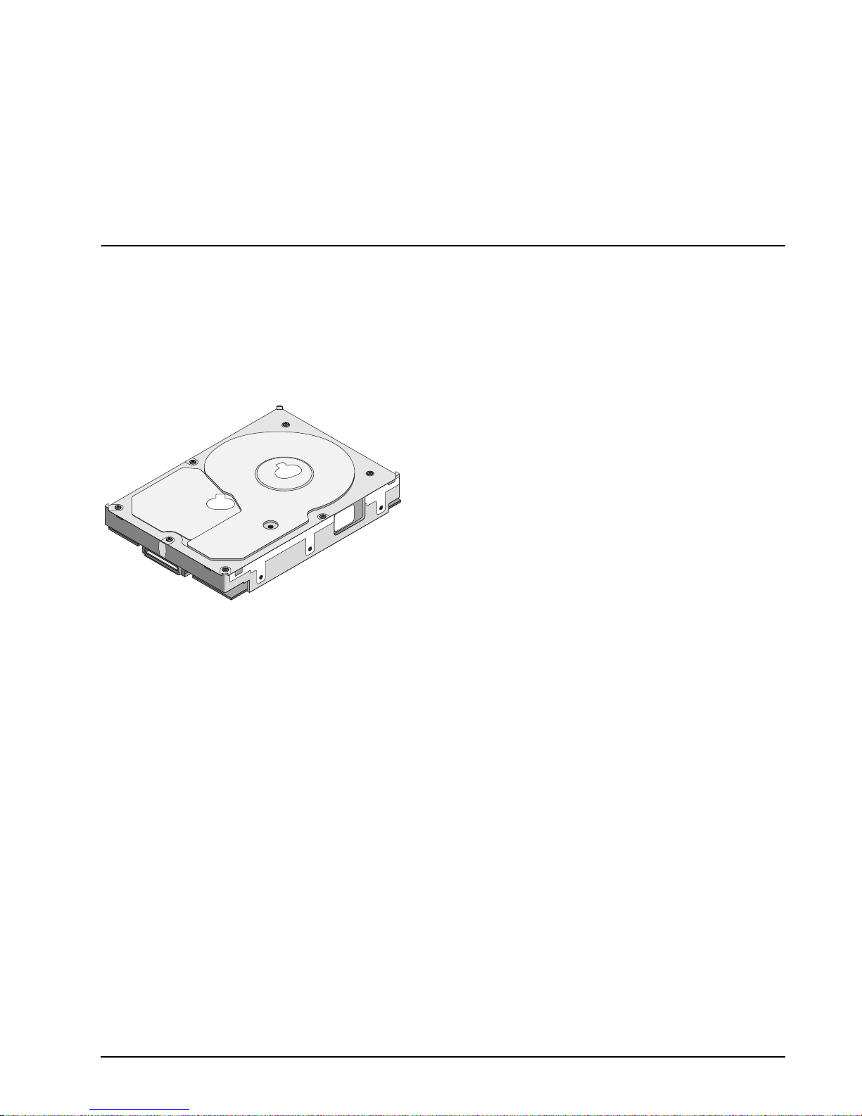
1.0 Scope
This manual describes Seagate Technology® LLC, Cheetah® 10K.7 FC 36GB (Fibre Channel) disc drives.
Cheetah 10K.7 FC drives support the Fibre Channel Arbitrated Loop and SCSI Fibre Channel Protocol specifi-
cations to the extent desc ribed in this manual. The F ibre Channel Interface Ma nual (part number 77767496)
describes the gener al Fibre Channe l Arbitrated Loop char acteristics o f this and other Seagate Fibre Channel
drives.
Figure 1. Cheetah 10K.7 FC family disc drive
Cheetah 10K.7 36GB FC Product Manual, Rev. A 1
Page 14

2 Cheetah 10K.7 36GB FC Product Manual, Rev. A
Page 15

2.0 Applicable standards and reference documentation
The drive has been developed as a system peripheral to the highest standards of design and construction. The
drive depends upon its host equ ipment to provide adequate power and envi ronment in order to achi eve opti-
mum performance and co mpliance with applicable indus try and governmental regulations. Special attention
must be given in the areas of safety, power distribution, shielding, audible noise control, and temperature regu-
lation. In particula r, the drive must b e s ecur el y mou nted i n o rde r to gua ra nte e th e s pe ci fie d p er formance char-
acteristics. Mounting by bottom holes must meet the requirements of Section 8.5.
2.1 Standards
The Cheetah 10K.7 FC family comp lies with Seagate standards as noted in th e appropriate sections of this
manual and the Seagate Fibre Channel Interface Manual, part number 77767496.
The Cheetah 10K.7 FC disc drive is a UL recognized component per UL1950, CSA certified to CAN/CSA
C22.2 No. 950-95, and VDE certified to VDE 0805 and EN60950.
2.1.1 Electromagnetic compatibility
The drive, as delivered , is designed for system integrati on and installation into a suitable encl osure prior to
use. As such the d rive is supplied as a subassembly and is not subject to Subpart B of Part 15 of the FCC
Rules and Regulation s nor the Radio Interference Reg ulations of the Canadian Departm ent of Communica-
tions.
The design characteristics of the drive serve to minimize radiation when installed in an enclosure that provides
reasonable shielding. As such, the drive is capable of meeting the Class B limits of the FCC Rules and Regula-
tions of the Canadian Department of Communications when properly packaged. However, it is the user’s
responsibility t o assure that the drive mee ts the appropriate EMI re quirements in their system. S hielded I/O
cables may be requir ed if the en closure do es not provi de adequate shieldi ng. If the I/O cab les are exte rnal to
the enclosure, shielded cables should be used, with the shields grounded to the enclosure and to the host con-
troller.
2.1.2 Electromagnetic susceptibility
As a component a ssembly, the drive is not requ ired to meet any susc eptibi lity perfor mance requ irements. It is
the responsibilit y of those integrating the dr iv e wit hin the ir s y ste ms to perform those tests req uire d a nd des ig n
their system to ensure th at equipment operating in the same sy stem as the drive or external to the syste m
does not adversely affect the performance of the drive. See Section Table 11, DC power requirements.
Cheetah 10K.7 36GB FC Product Manual, Rev. A 3
Page 16

2.2 Electromagnetic compliance
Seagate uses an inde pendent laborato ry to confirm comp liance with the directives/standa rds for CE Markin g
and C-Tick Marking. The drive was tested in a representative system for typical applications. The selected system represents the most popular characteristics for test platforms. The system configurations include:
• Typical current use microprocessor
• 3.5-inch floppy disc drive
• Keyboard
• Monitor/display
• Printer
• External modem
•Mouse
Although the test system with this Seagate model complies with the directives/standards, we cannot guarantee
that all systems will comply. The computer manufacturer or system integrator shall confirm EMC compliance
and provide the appropriate marking for their product.
Electromagnetic compliance for the European Union
If this model has the CE Marking it co mplies with the European Union requirements of the El ectromagnetic
Compatibility Directive 89 /336/EEC of 03 May 1989 as amend ed by Dir ective 92 /31/ EEC of 28 Apri l 1992 an d
Directive 93/68/EEC of 22 July 1993.
Australian C-Tick
If this model has th e C-Tick Marking it complies with the Austr alia/New Zeal and Standard AS/NZS3548 199 5
and meets the Electromagnet ic Compatibility (EMC) Framework requi rements of Australia’s Spectrum Management Agency (SMA).
Korean MIC
If this model has the Korean Ministry of Information and Communication (MIC) logo, it complies with paragraph
1 of Article 11 of the Electromagnetic Compatibility (EMC) Control Regulation and meets the Electroma gnetic
Compatibility Framework requirements of the Radio Research Laborator y (RRL) Ministry of Information and
Communication Republic of Korea.
Taiwanese BSMI
If this model has the Chinese National Standard (CNS) 13438 marking, it complies with Chinese National Standard (CNS) 13438 an d meets the Electromagnetic Compatibil ity (EMC) Framework requ irements of the Taiwanese Bureau of Standards, Metrology, and Inspection (BSMI).
2.3 European Union Restriction of Hazardous Substances (RoHS)
A new law, the European Union Restri ction of Hazardous Substances (RoHS) di rective, will res trict the pressence of chemical sub stances, includi ng Lead (Pb), in el ectronic pro ducts effective July 200 6. The directiv e’s
requirements have not been finalized. This drive is manufactured with components and materials that are
expected to comply with the RoHS directive when the directive takes effect.
4 Cheetah 10K.7 36GB FC Product Manual, Rev. A
Page 17

2.4 Reference documents
Cheetah 10K.7 36GB FC Installation Guide Seagate part number: 100384023
Fibre Channel Interface Manual Seagate part number: 77767496
ANSI Fibre Channel Documents
X3.230-1994 FC Physical and Signaling Interface (FC-PH)
X3.297.1997 FC-PH-2 Fibre Channel Physical and Signaling Interface-2
X3.303.1998 FC-PH-3 Fibre Channel Physical and Signaling Interface-3
X3.272-1996 FC Arbitrated Loop (FC-AL)
X3.269-1996 Fibre Channel Protocol for SCSI (FCP)
NCITS TR-19 Private Loop SCSI Direct Attach (PLDA)
NCITS TR-20 Fabric Loop Attachment (FC-FLA)
SFF-8045 Specification for 40-pin SCA-2 Connector with Parallel Selection
SFF-8067 Specification for 40-pin SCA-2 Connector with
Bidirectional Encl os ur e Servi ce s Interfa ce
ANSI Small Computer System Interface (SCSI) Documents
X3.131-1994 (SCSI-2)
X3.270-1996 (SCSI-3) Architecture Model
NCITS 305-199X (SCSI-3) Enclosure Services
Specification for Acoustic Test
Requirement and Procedures Seagate part number: 30553-001
Package Test Specification Seagate P/N 30190-001 (under 100 lb.)
Package Test Specification Seagate P/N 30191-001 (over 100 lb.)
In case of conflict between this document and any referenced document, this document takes precedence.
Cheetah 10K.7 36GB FC Product Manual, Rev. A 5
Page 18

6 Cheetah 10K.7 36GB FC Product Manual, Rev. A
Page 19

3.0 General description
Cheetah 10K.7 FC drives com bi ne gi ant m agn etores i stive (GMR) heads, partial respo nse/ma xi mu m li ke li hoo d
(PRML) read channel ele ctronics , embedded ser vo technolog y, and a Fibre Channel interface to pr ovide hig h
performance, high capac ity data storage f or a variety of systems including engineering wo rkstations, netwo rk
servers, mainframes, and supercomputers.
Cheetah 10K.7 FC drives supp ort the Fibre C hannel Ar bitrated Loo p (FC-AL) an d SCSI Fi bre Channel P roto-
col as described in the ANSI specifications, this document, and the Fibre Channel Interface Manual (part num-
ber 77767496) which describes the general interface characteristics of this drive. Cheetah 10K.7 FC drives are
classified as intellige nt peripherals and prov ide level 2 conformanc e (highest level) with the ANSI SCSI stan-
dard.
Never disassemble the HDA a nd do not at tempt to service ite ms in the sealed enclo su re (hea ds , m edi a, ac tu-
ator, etc.) as this requires special faci lities. The drive contains no parts replaceable by the user an d opening
the HDA for any reason voids your warranty.
Cheetah 10K.7 FC drives use a dedicated landing zone at the innermost radius of the media to eliminate the
possibility of d estroying or degrading d ata by landing in the data zone. The drive automatically goes to the
landing zone when power is removed.
An automatic shipping lock prevents potential damage to the heads and discs that results from movement dur-
ing shipping and handl in g. T he s hip pin g lo ck auto mat ic all y dis eng age s whe n powe r i s ap plied to the drive and
the head load process begins.
A high-performance ac tuator assembly with a low-inertia, balan ced, patented, straight arm design provides
excellent performance with min im al powe r diss ipation .
Cheetah 10K.7 36GB FC Product Manual, Rev. A 7
Page 20

3.1 Standard features
Cheetah 10K.7 FC drives have the following standard featur es :
• Integrated dual port FC-AL controller
• Concurrent dual port transfers
• Support for FC arbitrated loop, private and public attachment
• Differential copper FC drivers and receivers
• Downloadable firmware using the FC-AL interface
• Supports SCSI enclosure services via interface connector
• 128-deep task set (queue)
• Supports up to 32 initiators
• Drive selection ID and configuration options are set on the FC-AL backpanel or through interface commands. Jumpers are not used on the drive.
• Fibre Channel worldwide name uniquely identifies the drive and each port
• User-selectable logical block size (any multiple of four bytes, 512 to 528 bytes per logical block)
• Selectable frame sizes from 256 to 2,112 bytes
• Industry standard 3.5-inch low profile form factor dimensions
• Programmable logical block reallocation scheme
• Flawed logical block reallocation at format time
• Programmable auto write and read reallocation
• Reed-Solomon error correction code
• Sealed head and disc assembly (HDA)
• No preventive maintenance or adjustments required
• Dedicated head landing zone
• Automatic shipping lock
• Embedded Grey Code track address and servo wedge address to eliminate seek errors
• Self-diagnostics performed at power on
• 1:1 interleave
• Zone bit recording (ZBR )
• Vertical, horizontal, or top down mounting
• Dynamic spindle brake
• 8,192 Kbyte data buffer. See Section 4.5.
• Drive Self Test (DST)
• BackGround Media Scan (BGMS)
• Data Integrity Check
•Power Save
• Embedded servo design
• Reallocation of defects on command (Post Format)
• Fibre Channel interface transports SCSI protocol
3.2 Media description
The media used on the drive has an alumi num sub st rat e co ated with a thin fi lm magn eti c mater ia l, over coate d
with a proprietary protective layer for improved durability and environmental protection.
8 Cheetah 10K.7 36GB FC Product Manual, Rev. A
Page 21

3.3 Performance
• Programmable multi-segmentable cache buffer
• 200 Mbytes/sec maximum instantaneous data transfers per port
• 10K RPM spindle; average latency = 3.0 msec
• Command queuing of up to 128 commands
• Background processing of queue
• Supports start and stop commands
3.4 Reliability
• Annualized Failure Rate (AFR) of 0.62%
• LSI circuitry
• Balanced low mass rotary voice coil actuator
• Self-Monitoring Analysis and Reporting Technology (S.M.A.R.T.)
• Dithering
3.5 Formatted capacities
Standard OEM models are formatted to 512 bytes per block. The sector size is selectable at format time. Users
having the necessary equipm ent may mo dify the data block s ize before issuing a fo rmat comm and and obtain
different formatted capacities than those listed.
For 2 gigabit operation, sector sizes must be divisible by 8.
To provide a stable target capacity environment and at the same time provide users with flexibility if they
choose, Seagate recommends product planning in one of two modes:
1. Seagate designs specify capacity points at certain sector sizes that Seagate guarantees current and future
products will meet. We recommend custo mers use this capacity in their project pl anning, as it ensures a
stable operating point with bac kward and forwar d com patibility from gen eration to gener ation. The curren t
guaranteed operating points for this product are:
ST336807FC
Sector Size
Decimal Hex
512 71,687,372 445DCCC
514 70,512,692 433F034
520 70,197,546 6C4CCA
522 69,731,801 42805D9
524 68,788,592 419A170
2. Seagate drives also may be used at the maximum available capacity at a given sector size, but the excess
capacity above the guaranteed level will vary between 10K and 15K families and from generation to generation, depending on how each sector si ze actually for mats out for zone frequencies an d splits over serv o
bursts. This added capaci ty potent ial may range from 0.1 to 1.3 percent above th e guarant eed capacities
listed above. Us ing th e dr ives in th is mann er gi ves the ab so lute m aximu m capacity poten tial, but the user
must determine if the extra ca pacity potential is useful, or whether their assurance of backward and forward compatibility takes precedenc e.
3.5.1 Programmable drive capacity
Using the Mode Select command, the drive can change its capacity to something less than maximum. See the
Mode Select Parameter List table in the SCSI Interface Product Manual. Refer to the Parameter list block
descriptor number of blocks field. A value of zero in the number of blocks field indicates that the drive shall not
Cheetah 10K.7 36GB FC Product Manual, Rev. A 9
Page 22

change the capacity it i s currently forma tted to have. A number in the n umber of block s field that is less than
the maximum numbe r of LBAs changes th e total driv e capacity t o the val ue in the block des criptor number of
blocks field. A value greater than the maximum number of LBAs is rounded down to the maximum capacity.
3.6 Factory-install ed accessories
OEM standard drives are shipped with the Cheetah 10K.7 36GB FC Installation Guide (part number
100384023).
3.7 Factory-install ed options
You may order the follow ing items which are incorpor ated at the manufacturing fa cility during production or
packaged before shipping. Some of the options available are (not an exhaustive list of possible options):
• Other capacities can be ordered depending on sparing scheme and sector size requested.
• Single-unit shippi ng pack. The drive is normally shipped in bulk packag ing to provide maximum p rotection
against transit damage. Units shipped individually require additional protection as provided by the single unit
shipping pack. Users planning single unit distribution should specify this option.
• The Cheetah 10K.7 36GB FC Installation Guide, part number 100384023, is usually included with each
standard OEM drive shipped, but extra copies may be ordered.
• The Safety and Regulatory Agency Specifications, part number 75789 512, is usually included with each
standard OEM drive shipped, but extra copies may be ordered.
3.8 User-installed accessories
The following accessories are available. All kits may be installed in the field.
• Evaluation kit, part number 73473644.
This kit provides an adapter card (“T-card”) to allow cable connections for two FC ports and DC power.
• Single-unit shipping pack.
10 Cheetah 10K.7 36GB FC Product Manual, Rev. A
Page 23

4.0 Performance characteristics
This section provides detailed information concerning performance-related characteristics and features of
Cheetah 10K.7 FC drives.
4.1 Internal drive characteristics
ST336807FC
Drive capacity 36.8..................... ................................Gbytes (formatted, rounded off value)
Read/write data heads 1
Bytes per track 556...................... ................................Kbytes (average, rounded off values)
Bytes per surface 50.5..................... ................................Gbytes (unformatted, rounded off value)
Tracks per surface (total) 90,774................. ................................Tracks (user accessible)
Tracks per inch 105,000............... ................................TPI
Peak bits per inch 658...................... ................................KBPI
Internal data rate 470-944 .............. ................................Mbits/sec (variable with zone)
Disc rotation speed 10,000................. ................................rpm (+
Avg rotational latency 3.0....................... ................................msec
0.5%)
Cheetah 10K.7 36GB FC Product Manual, Rev. A 11
Page 24

4.2 Seek performance characteristics
4.2.1 Access time [4]
Not including controller overhead
(without disconnect) [1]
Drive level
Read Write
msec
Average—Typical [2] 4.9 5.4
Single Track—Typical [2] 0.45 0.65
Full Stroke—Typical [2] 9.9 10.5
4.2.2 Format command execution time (in minutes)
ST336807FC
Maximum (with verify)
Maximum (without veri fy )
4.2.3 Generalized performance characteristics
Minimum sector interleave 1 to 1
25
13
Data buffer transfer rate to/from disc media (one 512-byte sector):
ST336807FC
Minimum [3]* 59 MBytes/sec
Maximum [3] 118 MBytes/sec
Sustainable disc transfer rate:
ST336807FC
Minimum [3]* 39 MBytes/sec
Maximum [3] 80 MBytes/sec
Fibre Channel Interface maximum instantaneous transfer rate
1 GHz 2 GHz
106 Mbytes/sec* per port
(dual port = 212 Mbytes/
sec*)
Note. 1 Megabyte (MB) = 1,000,000 bytes.
Sector Sizes
Default is 512-byte data blocks.
212 Mbytes/sec* per
port (dual port = 424
Mbytes/sec*)
Logical block sizes
Default is 512-byte data blocks
Variable 512 to 528 bytes per sector in a multiple of 4 bytes per sector
Read/write consecutive sectors on a track Yes
12 Cheetah 10K.7 36GB FC Product Manual, Rev. A
.
Page 25

Flaw reallocation performance impact (for flaws reallocated at format time
using the spare sectors per sparing zone reallocation scheme.)
Overhead time for head switch in sequential mode
Overhead time for one track cylinder switch in sequential mode
Average rotational latency
*Assumes no errors and no relocated logical blocks. Rate measured from the start of the first logical block transfer to or
from the host.
Negligible
0.8 msec
1.2 msec (typical)
3.0 msec
Notes for Section 4.2.
[1] Execution time measured from receipt of the last byte of the Com mand Descriptor Block (CDB) to th e
request for a Status Byte Transfer to the Initiator (excluding connect/disconnect).
[2] Typi cal acc ess ti mes are meas ured under nomin al conditi ons o f tempe ratur e, voltage, and horiz ontal ori-
entation as measured on a representative sample of drives.
[3] Assumes system ability to support the rates listed and no cable loss.
[4] Access to data = access time + latency time.
4.3 Start/stop time
If the Motor Start option is disabled, the drive becomes ready within 25 seconds after DC power is applied. If a
recoverable error condition is detected during the start sequence, the drive executes a recovery procedure and
the time to become ready may exceed 25 seconds. Stop time is less than 30 seconds (maximum) from
removal of DC power.
If the Motor Start option is enabled, the internal controller accep ts the commands listed in the Fibre Channel
Interface Manual less than 3 s econds after DC power has been appli ed. After the Motor Start command has
been received, the drive becomes ready for normal operations within 25 seconds (excluding the error recovery
procedure). The Motor Start command can also be used to command the drive to stop the spindle.
There is no power control switch on the drive.
4.4 Prefetch/multi-segmented cache control
The drive provides a prefetch ( read look-ahead) and multi-se gmented cache control algori thms that in many
cases can enhan ce system performance. Cac he refers to the drive buffer stor age space when it is used in
cache operations . To sel ect this feature, th e host sends the Mode Sel ect command with the p roper values in
the applicable bytes in page 08h. Prefetch and cache operations are independent features from the standpoint
that each is enabled and dis abled indepe ndently using the Mode Select c ommand; however, in actual operation, the prefetch feature overlaps cache operation somewhat as described in sections 4.5.1 and 4.5.2.
All default cache and prefetch mode paramete r values (Mode Page 08 h) for standard OEM versions of this
drive family are given in Table 25.
4.5 Cache operation
Note. Refer to the Fibre Channel Interface Manual for more detail concerning the cache bits.
Of the 8,192 kbytes physical buffer space in the drive, 6,991 kbytes can be used as a cache. The buffer can be
divided into logical segments (using Mode Select Page 08h, byte 13) from which data is read and to which data
is written.
Cheetah 10K.7 36GB FC Product Manual, Rev. A 13
Page 26

The drive keeps track of the logical block addresses of the data stor ed in each segment of the buffer. If the
cache is enabled (see RCD bit in the Fibre Chann el In ter fac e M anua l), data reque ste d by the ho st wi th a r ea d
command is retrieved from the buffer, if possible, before any disc access is initiated. If ca che operation is not
enabled, the buffer (still segm ented with the required number of segments) is still used, but only as ci rcular
buffer segments during disc medium rea d operations (disregar ding Prefetch operation for the moment). That
is, the drive does not check in the buffer segments for the requested read data, but goes directly to the medium
to retrieve it. The retrieved data merely passes through some buffer segment on the way to the host. O n a
cache miss, all data transfers to the host are in accordance with buffer-full ratio rules. On a cache hit, the drive
ignores the buffer-full ratio rules. See the explanation provided with the information about Mode Page 02h (disconnect/reconnect control) in the Fibre Channel Interface Manual.
The following is a simplified description of the prefetch/cache operation:
Case A—read command is received and the first logical block is already in the cache:
1. Drive transfers to the initiator the first logical block requested plus all subsequent contiguous logical blocks
that are already in the cache. This data may be in multiple segments.
2. When a requested log ical block i s reached that is not in an y cache se gment, the dri ve fetches it and any
remaining requested lo gical b lock a ddres ses from th e disc and puts them in a seg ment o f the cache . The
drive transfers the r emaining requested l ogical blocks from t he cache to the host in a ccordance with the
Mode Select Disconnect/Reconnect parameters, page 02h.
3. If the prefetch feature is enabled, refer to section 4.5.2 for operation from this point.
Case B—A Read command requests data, and the first logical block is not in any segment of the cache:
1. The drive fetches th e requested logical blocks f rom the dis c and trans fers them into a se gment, and then
from there to the host in accordance with the Mode Select Disconnect/Reconnect parameters, page 02h.
2. If the prefetch feature is enabled, refer to section 4.5.2 for operation from this point.
During a prefetch, the drive cross es a cylinder boundary to fetc h data only if the Disco ntinui ty (DISC) bit is se t
to 1 in bit 4 of byte 2 of the Mode Select parameters page 08h. Default is zero for bit 4.
Each cache se gment is actually a s elf-contained circula r buffer whose length is an integer number of logical
blocks. The wrap-ar ound capability of the individual segm ents greatly enhances the cache’s overa ll performance, allowing a wide range of user-sele ctable configurations. The d rive supports operation of any integer
number of segments from 1 to 32. D ivide the 6 ,877 Kbyt es in the b uffer by the numbe r of seg ments to get the
segment size in bytes; then divide by the sector size to get the number of sectors per segment, any partial sectors remaining are not used. Default is 3 segments.
Note. The size of each segment is not reported by Mode Se nse command page 08h, bytes 14 and 15.
The value 0XFFFF is always reported regardless of the actual size of the segm ent . Se ndi ng a siz e
specification using the Mode Select command (byt es 14 and 15) does not set up a new segment
size. If the STRICT bit in Mode page 00h (byte 2, bit 1) is set to one , the driv e respon ds as it does
for any attempt to change an unchangeable parameter.
4.5.1 Caching write data
Write caching is a write operation by the drive th at mak es use of a drive buffer sto ra ge area where the data to
be written to the medium is stored while the drive performs the Write command.
If read caching is enabled (RCD=0), then data written to the medium is retained in the cache to be made available for future read cache h its. The same buffer space an d segme ntation is use d as set up for read functions .
The buffer segmentation s cheme is set up or changed independently, having nothing to do with the state of
RCD. When a write command is issued, i f RCD=0, the cache is first checke d to see if any logical blocks tha t
are to be written are a lready stored in the cache f rom a previous read or write comman d. If there are, the
respective cache segments are cleared. The new data is cached for subsequent Read commands.
14 Cheetah 10K.7 36GB FC Product Manual, Rev. A
Page 27

If the number of write data logical blocks exceed the size of the segment being written into, when the end of the
segment is reached, the data is written into the beginning of the same cache segment, overwriting the data that
was written there at the beginning of the operation; however, the drive does not overwrite data that has not yet
been written to the medium.
If write caching is enabled (WCE=1), then the drive may return Good status on a write command after the data
has been transferred into the cache, but befor e the data has been written to the medium. If an error oc curs
while writing the data to the medium, and Good status has already been returned, a deferred error will be generated.
The Synchronize Cache command may be used to force the drive to write all cached write data to the medium.
Upon completion of a Synchronize Cache command, all data received from previous write commands will have
been written to the medium.
Table 25 shows the mode default settings for the drive.
4.5.2 Prefetch operation
If the Prefetch fea ture i s ena bl ed, data in co nti guo us lo gi cal b lock s on t he d is c immediately beyond tha t whi ch
was requested by a Read c ommand are retrieved and stored in the buffer for immediate transfer from the
buffer to the host on subsequ ent Read com mands that request t hose logica l block s (this is tr ue even if cache
operation is disabled). Though the prefetch operation uses the buffer as a cache, finding the requested data in
the buffer is a prefetch hit, not a cache operation hit.
To ena ble Prefetch, use Mode S elect page 08h, byte 12, bit 5 (Disable Read Ahead—DRA bit). DRA bit = 0
enables prefetch.
Since data that is pr efetch ed r eplaces data alre ady in som e buffer s egmen ts, the ho st c an li mit the amou nt of
prefetch data to optimize system per formance. The Max Prefetch field (bytes 8 and 9) limits the amount of
prefetch. The drive does not use the Prefetch Ceiling field (bytes 10 and 11).
During a prefetch operation, the drive cros ses a cylinder boundary to fetch more data only if Mode param ete rs
page 08h, byte 2, bit 4 is set to 1 (Discontinuity—DISC bit).
When prefetch (read look -ahead) is enabled (enabled by DRA = 0), it opera tes under the control of ARLA
(Adaptive Read Look-Ahead). If the host uses software interleave, ARLA enables prefetch of contiguous
blocks from the disc when it senses that a prefetch hit will likely occur, even if two consecutive read operations
were not for physically co ntiguous blocks of data (e.g. “software interleave ”). ARLA disables pr efetch when it
decides that a prefetch hit will not likely occur. If the host is not using software interleave, and if two sequential
read operations are no t for c ontigu ous bloc ks of data, ARLA d isables prefetc h, but as long as se quentia l read
operations request contiguous blocks of data, ARLA keeps prefetch enabled.
4.5.3 Optimizing cache performance for desktop and server applications
Desktop and server applications require different drive caching operations for optimal performance. This
means it is difficult to provide a single configuration that meets both of these needs. In a desktop environment,
you want to con figure the cache to respond q uickly to repetitive ac cesses of multiple s mall segmen ts of data
without taking the time to “look ahea d” to the next conti guous segmen ts of data. In a server environ ment, you
want to configure the cac he to provide large volumes of seque ntial data in a non-repetitive manner. In this
case, the ability of the cache to “look ahead” to the next contiguous segmen ts of sequential data is a good
thing.
The Performance Mode (PM) bit contr ols the way the drive switches the cache buffer into different modes o f
segmentation. In “server mode” (PM bit = 0), the drive can dynamically cha nge the number of cache buffer
segments as needed to opt imize the performa nce, based on the command st ream from the hos t. In “desktop
mode” (PM bit = 1), the number of segments is maintained at the value defined in Mode Page 8, Byte 13, at all
times. For additio nal information about the PM bit , refer to the Unit Attention Parame ters page (00h) of the
Mode Sense command (1Ah) in the Fibre Channel Interface Product Manual, part number 77767496.
Cheetah 10K.7 36GB FC Product Manual, Rev. A 15
Page 28

16 Cheetah 10K.7 36GB FC Product Manual, Rev. A
Page 29

5.0 Reliability specifications
The following reli ability specifica tions assume co rrect host and drive operational interfa ce, including al l interface timings, power supply voltages, environmental requirements and drive mounting constraints
Seek error rate Less than 10 errors in 10
Read Error Rates
1
Recovered Data Less than 10 errors in 10
Unrecovered Data Less than 1 sector in 10
Miscorrected Data Less than 1 sector in 10
Interface error rate Less than 1 error in 10
Less than 1 error in 10
(see Section 9.6.4, "Differential PECL input." on page 68)
AFR 0.62%
Service life 5 years
Preventive maintenance None required
1. Error rate specified with automatic retries and data correction with ECC enabled and all flaws reallocated.
5.1 Error rates
8
seeks
12
bits transferred (OEM default settings)
15
bits transferred
21
bits transferred
12
bits transferred with minimum receive eye
14
bits transferred with typical receive eye
The error rates stated in this manual assume the following:
• The drive is operated in accordance with this manual usi ng DC power as defined in paragraph 6.2, " DC
power requirements."
• Errors caused by host system failures are excluded from error rate computations.
• Assume random data.
• Default OEM error r ecovery settings are applied. Thi s includes AWRE, ARRE, full read retries, fu ll write
retries and full retry time.
5.1.1 Recoverable Errors
Recovereable errors are those detected and corrected by the drive, and do not require user intervention.
Recoverable Data errors will use co rrection, although ECC on -the-fly is not considered for purposes of recov-
ered error specifica tio ns.
Recovered Data error rate is determine d using read bits transfer red for recove rable errors occurring dur ing a
read, and using write bits transferred for recoverable errors occurring during a write.
Cheetah 10K.7 36GB FC Product Manual, Rev. A 17
Page 30

5.1.2 Unrecoverable errors
15
Unrecoverable Data Errors (Sense Ke y = 03h) are s pecified at les s than 1 sect or in error per 10
bits trans-
ferred. Unrecoverable Data Errors resulting from the same cause are treated are 1 error for that block.
5.1.3 Seek errors
A seek error is defined as a fail ur e of the dr i ve to pos it ion the heads to the addressed t rack . After dete cti ng a n
initial seek error, the drive automatically performs an error recovery process. If the error recovery process fails,
a seek positioning error (Error code = 15h or 02h) will be reporte d with a Hardware error (04h) in t he Sense
Key. Recoverable seek errors are specified at Less than 10 er rors in 10
8
seeks. Unre covera ble se ek erro rs
(Sense Key = 04h) are classified as drive failures.
5.1.4 Interface errors
An interface error is defin ed as a failure of the receiver on a port to recover the d ata as transmitted by the
device port connected to the receiver. The error may be detected as a running disparity error, illegal code, loss
of word sync, or CRC error. The total error rate for a loop o f devices is the sum of the individu al device error
rates.
5.2 Reliability and service
You can enhance the r eliability of Cheetah 10K.7 SCS I disc drives by ensuring that the drive receives a dequate cooling. S ection 6.0 provides temperature measurements and other informa tion that may be used to
enhance the service life of the drive. Section 8.3 provides recommended air-flow information.
5.2.1 Annualized Failure Rate (AFR)
The production disc dr ive shall achieve an AFR of 0.62% when oper ated in an environm ent that ensures th e
HDA case temperatur es spec ified in Sectio n 6. 4 are not exce eded. S hort -term ex cursi ons u p to th e spec ification limits of the operating e nvironment will not affect AFR perfor mance. Continual or sustained operation at
case temperatures above the values shown in Section 6.4.1 may degrade product reliability.
Estimated power-on operation hours means power-up hours per disc drive times the total number of disc
drives in service. Ea ch dis c drive shall h ave accu mulate d at le ast nine months of operatio n. Data sha ll be ca lculated on a rolling average base for a minimum period of six months.
AFR is based on the following assumption s:
• 8,760 power-on hours per year.
• 250 average on/off cycles per year.
• Operations at nominal voltages.
• Systems will prov ide adequate coolin g to ensure the case temperatures specified in Sec tion 6.4.1 are not
exceeded.
Drive failure means any stoppage or substandard performance caused by drive malfunction.
A S.M.A.R.T. predictive failure indic ates that the drive i s deterior ating to an immin ent failu re and is co nside red
an AFR hit.
5.2.2 Preventive maintenance
No routine scheduled preventive maintenance is required.
18 Cheetah 10K.7 36GB FC Product Manual, Rev. A
Page 31

5.2.3 Hot plugging the drive
Inserting and removin g the drive on the FC-AL will i nterrupt loop o peration. T he interrupti on occurs when th e
receiver of the nex t device in t he loop mus t synchro nize to a differen t input si gnal. FC e rror detecti on mechanisms, character sync, running disparity, word sync, and CRC are able to detect any error. Recovery is initiated
based on the type of error.
The disc drive defau lts to the FC- AL Mo nitoring state, Pas s-thro ugh state, w hen it is powe red- on by swi tchin g
the power or hot plugg ed. The cont rol line to an optiona l port bypass c ircuit (exte rnal to th e drive), def aults to
the Enable Bypass state. If the bypass circuit is present, the next device in the loop will continue to receive the
output of the previous device to the newly inserted device. If the bypass circuit is not present, loop operation is
temporarily disrupted until the next device starts receiving the output from the newly inserted device and
regains synchronization to the new input.
The Pass-through state is disabled while the drive performs self test of the FC interface. The control line for an
external port bypass circuit remains in the Enable Bypass state while self test is running. If the bypass circuit is
present, loop operation may continue. If the bypass circuit is not present, loop operation will be halted while the
self test of the FC interface runs.
When the self test completes successfully, the control line to the bypass circuit is disabled and the drive enters
the FC-AL Initializing state. The receiver on the next device in the loop must synchronize to output of the newly
inserted drive.
If the self-test fails, the control line to the bypass circuit remains in the Enable Bypass state.
Note. It is the responsibili ty o f the sy s tems in teg ra tor to a ss ur e th at no tem per atu re, en ergy, voltage haz-
ard, or ESD potential haza rd is presented dur ing the hot connect/di sconnect oper ation. Discharge
the static electricity from the drive carrier prior to inserting it into the system.
Caution. The drive motor must come to a complete stop prior to changing the plane of operation. This time is
required to insure data integrity.
5.2.4 S.M.A.R.T.
S.M.A.R.T. is an acronym for Self-Mon itoring Ana lysis and Re porting Technology. Thi s technology is intende d
to recognize conditio ns that indicate imminent drive failure and is des igned to provide sufficient warn ing of a
failure to allow you to back up the data before an actual failure occurs.
Note. The drive’s firmware monitors specific attributes for degradation over time but can’t predict instanta-
neous drive failures.
Each monitored a ttrib ute has b een sele cted to moni tor a specifi c se t of fai lure c onditi ons in th e oper ating performance of the drive and the thresholds are optimized to minimize “false” and “failed” predictions.
Controlling S.M.A.R.T.
The operating mode of S.M.A.R.T. is controlled by the DEXCPT and PERF bits on the Informational Exceptions
Control mode page (1Ch). Use th e DEXCPT bit to ena ble or disab le the S.M. A.R.T. feature. Setting th e DEXCPT bit disables all S.M.A.R.T. functions. When enabled, S.M.A.R.T . collects on-line data as the drive performs
normal read and write operations. When the PERF bit is set, the drive is consi dered to be in “On-line Mod e
Only” and will not perform off-line functions.
You can measure off-line attr ibutes and for ce the drive to sa ve the data by usi ng the Rezero Uni t command.
Forcing S.M.A.R.T. resets the timer so that the next scheduled interrupt is in two hours.
You can interrogate the drive through the host to determine the time remaining before the next scheduled measurement and data logging process occurs. To accomplish this, issue a Log Sense command to log page 0x3E.
This allows you to c ontrol when S.M.A.R.T. interruptions occur. Forcing S.M.A.R.T. w ith the RTZ command
resets the timer.
Cheetah 10K.7 36GB FC Product Manual, Rev. A 19
Page 32

Performance impact
S.M.A.R.T. attribute data is saved to the disc so that the events that ca used a predictive fai lure can be recr eated. The drive measures and sav es paramete rs once ever y two hours su bject to an id le period on the FC-A L
bus. The process o f meas uring off-l ine att ribute da ta and saving data to the di sc is uninte rruptable. The max imum on-line only processing delay is summarized below:
Maximum processing delay
S.M.A.R.T. delay times
On-line only delay
DEXCPT = 0, PERF = 1
60 milliseconds
Fully-enabled delay
DEXCPT = 0, PERF = 0
370
milliseconds
Reporting control
Reporting is controlled by the MRIE bits in the Inform ational Exceptio ns Control mode page (1Ch). Subject to
the reporting metho d, t he firmw are w ill is sue to the h ost a n 0 1-5Dxx sense code. The error code is pr eserve d
through bus resets and power cycles.
Determining rate
S.M.A.R.T . monitors the rate at which errors occur and signals a predictive failure if the rate of degraded errors
increases to an unacceptable level. To determine rate, error events are logged and compared to the number of
total operations for a given attribu te. The in terval de fine s the numb er of operati ons over which to mea sure the
rate. The counter that keeps track of the current number of operations is referred to as the Interval Counter.
S.M.A.R.T. measures error rates. All errors for each monitored attribute are recorded. A counter keeps track of
the number of errors for the current interval. This counter is referred to as the Failure Counter.
Error rate is the number of errors per operation. The algorithm that S.M.A.R.T. uses to record rates of error is to
set thresholds for the number of errors an d their inte rval. If the nu mber of error s exceed s the thr eshold bef ore
the interval expires, the error rate i s considered to be unacc eptable. If the number of errors does not exceed
the threshold before the interval expires, the error rate is considered to be acceptable. In either case, the interval and failure counters are reset and the process starts over.
Predictive failures
S.M.A.R.T. signals predictive failures when the drive is performi ng unacc eptably for a peri od of time. The fir mware keeps a running count of the number of times the error rate for each attribute is unacceptable. To accomplish this, a cou nter is i ncremen ted each time the error rat e is un acceptable and decr emented (not to e xceed
zero) whenever t he error ra te is a cceptabl e. If the co unter contin ually in crem ents such that it reache s the pr edictive threshol d, a predictive failure is signaled. This counter is r eferred to as the Failure H istory Counter.
There is a separate Failure History Counter for each attribute.
5.2.5 Thermal monitor
Cheetah 10K.7 SCSI drives implement a temperature warning system which:
1. Signals the host if the temperature exceeds a value which would threaten the drive.
2. Signals the host if the temperature exceeds a user-specified value.
3. Saves a S.M.A.R.T. data frame on the drive which exceed the threatening temperature value.
A temperature sensor monito rs the drive temperature and is sues a warning over the int erface when the temperature exceeds a s et threshol d. The temper ature is measured at power-up an d then at te n-minute intervals
after power-up.
20 Cheetah 10K.7 36GB FC Product Manual, Rev. A
Page 33

The thermal monitor syste m generates a wa rning code of 01- 0B01 when the temp erature exceed s the specified limit in compl iance with the SCSI standard. T he drive temperature is repo rted in the FRU code field o f
mode sense data. You can use this information to determine if the warning is due to the temperature exceeding
the drive threatening temperature or the user-specified temperature.
This feature is controlled by the Enable Warning (EWasc) bit, and the reporting mechanism is controlled by the
Method of Reporting Informational Exceptions field (MRIE) on the Informational Exceptions Control (IEC)
mode page (1Ch).
The current algorithm impl ements two temperature trip points. The first trip point is set at 68°C which is the
maximum temperatur e limit a ccordi ng to th e dri ve spec ific ation. T he secon d trip point is us er-se lectable using
the Log Select command. The reference temperature parameter in the temperature log page (see Table 1) can
be used to set this trip point. The default value for this drive is 68°C, however, you can set it to any value in the
range of 0 to 68°C. If you specify a temperature g reater than 68°C in this fi eld, the temperature is rou nded
down to 68°C. A sense code is sent to the host to indicate the rounding of the parameter field.
Table 1: Temperature Log page (0Dh)
Parameter Code Description
0000h Primary Temperature
0001h Reference Temperature
When the first temperature trip point is exceeded, S.M.A.R.T. data is collected and a frame is saved to the disc.
5.2.6 Drive Self Test (DST)
Drive Self Test (DST) is a technolo gy designed to recognize dri ve fault conditions that qualify the drive as a
failed unit. DST validates the functionality of the drive at a system level.
There are two test coverage options implemented in DST:
1. Extended test
2. Short text
The most thorough option is the extended test that performs various tests on the drive and scans every logical
block address (LBA ) of the drive. The s hort test is time-r estricted and limited i n length—it does n ot scan the
entire media surface, but does some fundamental tests and scans portions of the media.
If DST encounters an er ror during either of these tests, i t reports a fault condition. If the dr ive fails the test,
remove it from service and return it to Seagate for service.
Cheetah 10K.7 36GB FC Product Manual, Rev. A 21
Page 34

5.2.6.1 DST Failure Definition
The drive will presen t a “diagnostic failed” con dition through the self-te sts results value of the diagnos tic log
page if a functional failur e is enco untered du ring DST. The channel and servo parameters are not mod ified to
test the drive more strin gently, and the number of retries are not redu ced. All retries and recovery proce sses
are enabled during the test. If data is recoverable, no failure condition will be reported regardless of the number
of retries required to recover the data.
The following conditions are considered DST failure conditions:
• Seek error after retries are exhausted
• Track-follow error after retries are exhausted
• Read error after retries are exhausted
• Write error after retries are exhausted
Recovered errors will not be reported as diagnostic failures.
5.2.6.2 Implementation
This section provides all of the information necessary to implement the DST function on this drive.
5.2.6.2.1 State of the drive prior to testing
The drive must be in a ready state before issuing the Send Diagno stic command . There are multipl e reasons
why a drive may not be ready, some of which are valid conditions, and not errors. For example, a drive may be
in process of doing a format, or another DST. It is the responsibility of the host application to determine the “not
ready” cause.
While not technically part of DST, a Not Ready condition also qualifies the drive to be returned to Seagate as a
failed drive.
A Drive Not Ready condition is reported by the drive under the following conditions:
• Motor will not spin
• Motor will not lock to speed
• Servo will not lock on track
• Drive cannot read configuration tables from the disc
In these conditions, the drive responds to a Test Unit Ready command with an 02/04/00 or 02/04/03 code.
5.2.6.2.2 Invoking DST
To in voke DST, submit the Send Diagnostic comman d with the ap propriate Fun ction Code (001b for the short
test or 010b for the extende d test) in bytes 1, bits 5, 6, and 7. Ref er to the Fibre Channel Interf ace Product
Manual, part number 77767496, for additional information about invoking DST.
5.2.6.2.3 Short and extended tests
DST has two testing options:
1. short
2. extended
These testing options are described in the following two subsections.
Each test consists of th ree s egm ents: a n el ec tric al test segm ent, a servo test segment , and a rea d/v er ify s ca n
segment.
22 Cheetah 10K.7 36GB FC Product Manual, Rev. A
Page 35

Short test (Function Code: 001b)
The purpose of the short test is to provide a time-l imit ed te st tha t t e sts as m uch of the drive as possible within
120 seconds. The shor t test does not scan the entire me dia surface, but does some funda mental tests and
scans portions of the media. A complete read/verify scan is not performed and only factual failures will report a
fault condition. This option provides a quick confidence test of the drive.
Extended test (Function Code: 010b)
The objective of the extended test option is to empirically test critical drive components. For example, the seek
tests and on-track operations tes t the pos it ion ing mec han ism. T he read operation tests the read head element
and the media surface. The write element is tested throu gh read/write/read operations. The inte grity of the
media is checked through a r ead/verif y scan of the med ia. Motor functio nality is tested by d efault as a part of
these tests.
The anticipated length of the Extended test is reported through the Control Mode page.
5.2.6.2.4 Log page entries
When the drive begi ns DST, it creates a new entry in the Self -te st Resul ts Log page . The new entr y is c reated
by inserting a new self-test parameter block at the beginning of the self-test results log parameter section of the
log page. Existing da ta will be moved to make room f or the new parameter block. The dr iv e rep or ts 20 par ameter blocks in the log page. If there are more than 20 parameter blocks, the least recent parameter block will be
deleted. The new parameter block will be initialized as follows:
1. The Function Code field is set to the same value as sent in the DST command
2. The Self-Test Results Value field is set to Fh
3. The drive will store the log page to non-volatile memory
After a self-test is complete or has been aborted, the dr i ve upda tes the Sel f- Test Results Val ue fiel d in its Se lf-
Test Results L og pa ge in n on- v ola til e m emo ry. The host may use Log Sense to read the results from up to th e
last 20 self-tests performed by the drive. The self-test results value is a 4-bit field that reports the results of the
test. If the field is zero, the drive passed with no erro rs detected by the DST. If the field is not zero, the test
failed for the reason reported in the field.
The drive will report th e failure condition and LBA (i f applicable) in the Self-tes t Results Log parameter. The
Sense key, ASC, ASCQ, and FRU are used to report the failure condition.
5.2.6.2.5 Abort
There are several ways to abort a diagnostic. You can use a SCSI Bus Reset or a Bus Device Reset message
to abort the diagnostic.
You can abort a DST executing in backgrou nd mode by us ing the abor t code in the DS T Functio n Code field .
This will cause a 01 ( self-test aborted b y the application cl ient) code to appear i n the self-test results v alues
log. All other abort mechanisms will be reported as a 02 (self-test routine was interrupted by a reset condition).
5.2.7 Product warranty
Beginning on the date of shi pm ent to the cu stomer and continuing for a per i od of five years, Seagate warrants
that each product (inclu ding componen ts and subassemb lies) that fails to fu nction prope rly under normal use
due to defect in materials or workmanship or due to noncon formance to the applicable spec ifications will be
repaired or replaced, at Seag ate’s option and at no charge to the customer, if returned by customer at customer’s expens e to Seagate’s designated faci lity in accordance wit h Seagate’s warranty proced ure. Seagate
will pay for transporting the repair or replacement item to the customer. For more detailed warranty information,
refer to the standard te rms and conditio ns of purchase fo r Seagate produc ts. Refer to Section 1 0 for contact
information.
Cheetah 10K.7 36GB FC Product Manual, Rev. A 23
Page 36

Shipping
When transporting or shipping a drive, use only a Seagate-approved container. Keep your original box.
Seagate approved containers are easily identified by the Seagate Approved Package label. Shipping a drive in
a non-approved container voids the drive warranty.
Seagate repair center s may refuse receipt of co mponents improperly packaged or obviously da mag ed in tr ansit. Contact your au thorized S eagate dist ributor to purchas e additio nal boxe s. Seagat e recom mends sh ipping
by an air-ride carrier experienced in handling computer equipment.
Product repair and return information
Seagate customer se rvice centers are th e only facilities au thorized to service Sea gate drives. Seagate d oes
not sanction any third-party repair fac ilities. Any unauthorized repair or tamper ing with the factory seal voids
the warranty.
24 Cheetah 10K.7 36GB FC Product Manual, Rev. A
Page 37

6.0 Physical/electrical spe cifications
This section provides information relating to the physical and electrical characteristics of the drive.
6.1 AC power requirements
None.
6.2 DC power requirements
The voltage and current requi rements for a single drive are shown below. Values indicated apply at the drive
connector.
Table 11:
Voltage +5V +12V [2] +5V +12V [2]
Regulation [5] ±5% ±5% [2] ±5% ±5% [2]
Avg idle current DC X [1] [7]
Maximum starting current
(peak DC) DC 3σ [3]
(peak AC) AC 3σ [3]
Delayed motor start (max) DC 3σ [1] [4]
Peak operating current:
Typical DC X [1] [6]
Maximum DC 3σ [1]
Maximum (peak) DC 3σ
ST336807FC DC power requirements
ST336807FC
1 Gbit 2 Gbit
Notes (Amps) (Amps) (Amps) (Amps)
0.86 0.34 0.92 0.34
1.02 1.58 1.08 1.57
1.18 3.48 1.50 3.57
0.60 0.09 0.62 0.09
0.93 0.77 0.99 0.80
0.94 0.78 1.00 0.81
1.78 2.44 1.86 2.50
[1] Measured with average reading DC ammeter. Instantaneous +12V curren t peaks will excee d these val-
ues. Power supply at nominal voltage. Number of drives tested = 6, 35 Degrees C ambient.
[2] For +12 V, a –10 % tol er an ce is allowed during initi al sp in dle s tart but must return to ±5% before reaching
10,000 RPM. The ±5% must be maintained after the drive signifi es that its power-up seq uence has bee n
completed and that the drive is able to accept selection by the host initiator.
[3] See +12V current profile in Figure 2.
[4] This condition occurs when the M otor Start option is enabled and the driv e has not yet receiv ed a Start
Motor command.
Cheetah 10K.7 36GB FC Product Manual, Rev. A 25
Page 38

[5] See paragraph 6.2.1, "Conducted noise immunity." Specified voltage tolerance includes ripple, noise, and
transient response.
[6] Operating condition is defined as random 8 block reads at 254 I/Os per second.
Current and power sp ecified at no minal voltages . Decreasi ng +5 volt s upply by 5 % increase s 5 volt cur rent by <0.5%. Decreasing +12 volt supply by 5% increases 12 volt current by 1.4%.
[7] During idle, the drive heads are relocated every 60 seconds to a random l ocation within the ban d from
track zero to one-fourth of maximum track.
General DC power requirement notes.
1. Minimum current l oading fo r each sup ply voltage is not les s than 1. 2% of the ma ximum o perating current
shown.
2. The +5V and +12V supplies should employ separate ground returns.
3. Where power is provided to multiple drives from a common supply, careful consideration for individual
drive power requirem ents s hou ld b e no ted. Whe re mul ti ple uni ts are pow er ed o n s imu ltaneou sl y, the peak
starting current must be available to each device.
4. Parameters, other than spindle start, are measured after a 10-minute warm up.
5. No terminator power.
6.2.1 Conducted noise immunity
Noise is specified a s a periodic an d random distri bution of frequenc ies covering a band from DC to 10 MHz.
Maximum allowed noise values given below are peak to peak measurements and apply at the drive power connector.
+5 V = 250 mV pp from 100 Hz to 20 MHz.
+12 V = 800 mV pp from 100 Hz to 8 KHz.
450 mV pp from 8 KHz to 20 KHz.
250 mV pp from 20 KHz to 5 MHz.
6.2.2 Power sequencing
The drive does not require power sequenci ng. The drive prote cts against inadver tent writing dur ing power-up
and down.
26 Cheetah 10K.7 36GB FC Product Manual, Rev. A
Page 39

6.2.3 Current profiles
Figures 2 and 3 identify the drive current profiles. The current during the various times is as shown:
Note: All times and currents are typical. See Table 11 for maximum current requiremST336807FC
Figure 2. Typical ST336807FC drive, 2 Gbit, +12V current profile
Figure 3. Typical ST336807FC drive, 2 Gbit, +5V current profile
Cheetah 10K.7 36GB FC Product Manual, Rev. A 27
Page 40

6.3 Power dissipation
ST336807FC
Typical power dissipation under idle conditions is 8.38 watts (28.60 BTUs per hour) during 1 Gbit operation.
Typical power dissipation under idle conditions is 8.68 watts (29.62 BTUs per hour) during 2 Gbit operation.
To obtain operati ng power for typical random read opera tions, refer to the follo wing I/O rate curve (see Figure
4). Locate the typica l I/O rate for a drive i n your syst em on the h orizontal axis and read th e correspond ing +5
volt current, +12 vol t c ur rent, and tota l wa tts on the v er ti cal a xi s. To calculate BTUs per hour, multiply watts by
3.4123.
ST373207FC DC CURRENT/POWER vs THROUGHPUT (1Gb ) Random 8 Block Reads
1.8 00
1.6 00
1.4 00
1.2 00
18 .00
16 .00
14 .00
12 .00
5Volt A
12 Vo l t A
Watts
Power (watts)
1.0 00
0.800
Amperes
0.600
0.400
0.200
0.000
0.0 50.0 100.0 150.0 200.0 250.0 300.0
I/Os per Second
ST373207FC DC CURRENT/POWER vs THROUGHPUT (2Gb) Random 8 Block Re ad s
1.800
1.600
1.400
1.200
1.000
0.800
Amperes
0.600
0.400
10 .00
8.00
6.00
4.00
2.00
0.00
18 .00
16 .00
14 .00
12 .00
10 .00
8.00
6.00
4.00
5Volt A
12 V o lt A
Watts
Power (watts)
0.200
0.000
0.0 50.0 100.0 150.0 200.0 250.0 300.0
I/Os per Second
Figure 4. ST336807FC DC current and power vs. input/output operations per second
28 Cheetah 10K.7 36GB FC Product Manual, Rev. A
2.00
0.00
Page 41

6.4 Environmental limits
H
C
Tempe ratur e an d hum idi ty val ues ex per i enced by the drive mus t be suc h that c ond ens ation does not oc c ur on
any drive part. Altitude and atmospheric pressu re specifications are refer enced to a standard day at 58.7 °F
(14.8°C). Maximum wet bulb temperature is 82°F (28°C).
6.4.1 Temperature
a. Operating
The maximum allowable continuous or sustained HDA case temperature for the rated AFR is 122°F (50°C)
The maximum allowable HDA case temperature is 60°C. Occasional excursions of HDA case temperatures
above 122°F (50°C) or below 41°F (5°C) may occur without impact to specified AFR. Continual or sustained
operation at HDA case temperatures outside these limits may degrade AFR.
Provided the HDA case temperatures limits are met, the drive meets all specifications over a 41°F to 131°F
(5°C to 55°C) drive ambient temperatu re range with a maximum temper ature gradient of 36°F (20°C) per
hour. Air flow may be needed in the drive enclosure to keep within this range (see Section 8.3). Operation at
HDA case temperatures outside this range may adversely affect the drives ability to meet specifications. To
confirm that the require d cooling for the electronic s and HDA case is provided, pla ce the drive in its final
mechanical configurat ion, perform random write/read operatio ns and measure the HDA cas e temperature
after it has stabilized.
b. Non-operating
–40° to 158°F (–40° to 70°C) package ambient with a maxim um gradient of 36°F (20°C) per hour. This
specification assumes that the drive is packaged in the shipping container designed by Seagate for use with
drive.
DA Temp.
heck Point
Figure 5. Location of the HDA Temperature check point
1.0"
.5"
6.4.2 Relative humidity
The values below assume that no condensation on the drive occurs.
a. Operating
5% to 95% non-condensing relative humidity with a maximum gradient of 10% per hour.
b. Non-operating
5% to 95% non-condensing relative humidity.
6.4.3 Effective altitude (sea level)
a. Operating
–1,000 to +10,000 feet (–305 to +3,048 meters)
b. Non-operating
–1,000 to +40,000 feet (–305 to +12,210 meters)
Cheetah 10K.7 36GB FC Product Manual, Rev. A 29
Page 42

6.4.4 Shock and vibration
Shock and vibration lim its specifie d in this docum ent are measur ed directl y on the driv e chassis . If the drive is
installed in an e nclosure to which the stated shock and/or vib ration cr iteria is applied, res onances m ay occur
internally to the enclosure resulting in drive movement in excess of the stated limits. If this situation is apparent,
it may be necessary to modify the enclosure to minimize drive movement.
The limits of shock and vibr ation define d within this doc ument are spec ified with the d rive mounted by any of
the four methods shown in F igure 6, and in acc ordance with t he restrictions of Section 8.5. O rientation of the
side nearest the LED may be up or down.
6.4.4.1 Shock
a. Operating—normal
The drive, as installed for normal operation, shall operate error free while subjected to intermittent shock not
exceeding 15 Gs at a maximum duration of 11 msec (half sinewave). The drive, as ins talled for normal
operation, shall operate error free while subjected to intermittent shock not exceeding 60 Gs at a maximum
duration of 2 msec (half sinewave). Shock may be applied in the X, Y, or Z axis.
b. Operating—abnormal
Equipment, as installed for norma l operation, does not incu r physical damage while subjected to intermittent shock not exce eding 40 Gs at a maximum duratio n of 11 msec (half sinewave). Shock oc curring at
abnormal levels may promote degraded operational performance during the abnormal shock period. Specified operational performance will continue when normal operating shock levels resume. Shock may be
applied in the X, Y, or Z axis. Shock is not to be repeated more than two times per second.
c. Non-operating
The limits of non-operating shock shall apply to all c onditions of handl ing and transpo rtation. This inc ludes
both isolated drives and integrated drives.
The drive subjected to nonrepetitive sh ock not exceeding 7 5 Gs at a maximu m duration of 11 msec (half
sinewave) shall n ot exh ibit dev ice d amage or pe rformanc e deg radation . Sh ock may be ap plied in the X, Y,
or Z axis.
The drive subjected to no nrepetitive shock not ex ceeding 225 Gs at a maximu m duration of 2 msec (hal f
sinewave) does not exhibi t device dam age or pe rforman ce degr adati on. Shock m ay be appl ied in th e X, Y,
or Z axis.
The drive subjected to non repetiti ve shock not excee ding 120 Gs at a ma ximu m duration of 0.5 mse c (half
sinewave) does not exhibi t device dam age or pe rforman ce degr adati on. Shock m ay be appl ied in th e X, Y,
or Z axis.
d. Packaged
Disc drives shipped as loose load (no t palletized) g eneral frei ght will b e packaged to w ithstand drops f rom
heights as defined in the table below. For additional details refer to Seagate specifications 30190-001
(under 100 lbs/45 kg) or 30191-001 (over 100 lbs/45 Kg).
Package size Packaged/product weight Drop height
<600 cu in (<9,800 cu cm) Any 60 in (1524 mm)
600-1800 cu in (9,800-19,700 cu cm) 0-20 lb (0 to 9.1 kg) 48 in (1219 mm)
>1800 cu in (>19,700 cu cm) 0-20 lb (0 to 9.1 kg) 42 in (1067 mm)
>600 cu in (>9,800 cu cm) 20-40 lb (9.1 to 18.1 kg) 36 in (914 mm)
Drives packaged in single or mul tipacks with a gross weight o f 20 pounds (8.95 k g) or less by Se agate for
general freight ship ment shal l withstand a drop t est from 48 inches (1, 070 mm) aga inst a co ncrete floor or
equivalent.
30 Cheetah 10K.7 36GB FC Product Manual, Rev. A
Page 43

Z
Y
X
Figure 6. Recommended mounting
X
Z
Y
Cheetah 10K.7 36GB FC Product Manual, Rev. A 31
Page 44

6.4.4.2 Vibration
a. Operating - normal
The drive as installed for normal ope ration, shall comply with the complete specif ied performance while
subjected to continuous vibration not exceeding
5-500 Hz @ 1.0 G (zero to peak)
Vibration may be applied in the X, Y, or Z axis.
Operating normal translational random flat profile
10 - 400 Hz 0.5 GRMS (grams root mean square)
b. Operating - abnormal
Equipment as installed for normal operation shall not in cur physical damage while subj ected to periodic
vibration not exceeding:
15 minutes of duration at major resonant frequency
5-500 Hz @ 1.5 G (X, Y, or Z axis)
Vibration occurring at these levels may degrade operational performance during the abnormal vibration
period. Specified operational performance will continue when normal operating vibration levels are
resumed. This assumes system recovery routines are available.
Operating abnormal translational random flat profile
10 - 400 Hz 1.2 GRMS (grams root mean square)
c. Non-operating
The limits of non-operating vibration shall apply to all conditions of handling and transportation. This
includes both isolated drives and integrated drives.
The drive shall not i ncur ph ysi cal damag e or d egrad ed perfor manc e as a result of con tinuous vibra tion no t
exceeding
5-22 Hz @ 0.040 inches (1.02 mm) displacement (zero to peak)
22-500 Hz @ 3.00 G
Vibration may be applied in the X, Y, or Z axis.
Non-operating translational random flat profile
10 - 400 Hz 1.2 GRMS (grams root mean square)
6.4.5 Air cleanliness
The drive is designed to operate in a typical office environment with minimal environmental control.
6.4.6 Corrosive environment
Seagate electronic driv e components pass accelerated cor rosion testing equivalent to 10 years exposure to
light industrial envir onments containi ng sulfuro us gases, chlorine an d nitric oxide , classes G and H per ASTM
B845. However, this accelerated testing cannot duplicate every potential application environment.
Users should use cauti on exposing any ele ctronic compo nents to uncontrolled c hemical pollutan ts and corrosive chemicals as electronic drive component reliability can be affected by the installation environment. The silver, copper, nickel and gold films us ed in Sea gate produc ts are especi ally sensitiv e to the presen ce of sulfide ,
chloride, and nitrate contaminants. Sulfur is found to be the most damaging. In addition, electronic components
should never be ex pose d to c ondensin g water on the surfac e of th e pri nted cir cuit bo ard a ssembly (PCBA ) or
exposed to an ambient relative humidity greater than 95%. Materials used in cabinet fabrication, such as vulcanized rubber, that can outgas corros ive compounds should be m inimized or e liminated. The us eful life of any
electronic equipment may be extended by replacing materials near circuitry with sulfide-free alternatives.
32 Cheetah 10K.7 36GB FC Product Manual, Rev. A
Page 45

6.4.7 Acoustics
Sound power during idle mode shall be 3.3 bels typic al, or bette r, when measured to ISO 777 9 specifi cation.
There will not be any discrete tones more than 10 dB above the masking nois e on typical drives when measured according to Sea gate specificat ion 30553-001 . There will not be a ny tones more than 24 dB above the
masking noise on any drive.
6.4.8 Electromagnetic susceptibility
See Section 2.1.2.
6.5 Mechanical specifications
The following nominal di men sion s ar e exc lusiv e of the dec or at iv e front panel acces s ory. However, dimensions
of the front panel are shown in figure below. Refer to Figure 7 for detailed mounting configu ratio n dimens ions.
See Section 8.5, “Drive mounting.”
Height: 1.000 in 25.4 mm
Width: 4.000 in 101.6 mm
Depth: 5.75 in 146.05 mm
Weight: 1.6 pounds 0.726 kilograms
Cheetah 10K.7 36GB FC Product Manual, Rev. A 33
Page 46

B
-Z-T//
-X-U
-Z-
H
L
S
[1]
J
K
-Z-
R
-X-N
A
M
P
F
[1]
C
-X-
Notes:
Mounting holes are 6-32 UNC 2B, three
[1]
on each side and four on the bottom.
Max screw penetration into side of drive
is 0.15 in. (3.81 mm). Max screw
tightening torque is 6.0 in-lb (3.32 nm)
with minimum full thread engagement of
0.12 in. (3.05 mm).
Dimension Table
Inches
1.028
A
B
C
D
E
F
H
J
K
L
M
N
P
R
S
T
U
5.787
4.000
3.750
0.125
1.750
1.122
4.000
0.250
1.638
0.181
.015
1.625
1.469
0.276
.015
.015
max
max
± .010
± .010
± .010
± .010
± .020
± .010
± .010
± .010
± .020
max
± .020
± .020
± .040
max
max
Millimeters
26.10
147.00
101.60
95.25
3.18
44.45
28.50
101.60
6.35
41.60
4.60
.038
41.28
37.31
7.00
0.38
0.38
max
max
± .25
± .25
± .25
± .25
± .50
± .25
± .25
± .25
± .50
max
± .50
± .50
± 1.02
max
max
E
D
Figure 7. Mounting configuration dimension s
34 Cheetah 10K.7 36GB FC Product Manual, Rev. A
Page 47

7.0 Defect and error management
The drive, as deli ve re d, c om pl ies w ith thi s pr odu ct ma nual. The read erro r ra tes an d s pe cif ied storage capacities are not dependent upon use of defect management routines by the host (initiator).
Defect and error managem ent in the SCSI protocol involves the drive internal defect/error m anagement and
FC-AL system error con siderations (errors in communicatio ns between the initiator and the drive). Tools for
use in designing a defect/er ror manag ement pla n are brie fly outli ned in th is sectio n. Referen ces to o ther se ctions are provided when necessary.
7.1 Drive internal defects/errors
During the initial drive format operation at the factor y, media defects are identified, tagged as being unusable ,
and their locations recorded on the dr ive primary defects lis t (referred to as the “ P’ list and also as the ETF
defect list). At factory format time, these known defects are also reallocated, that is, reassigned to a new place
on the medium and the lo cation listed in the defects reallocat ion table. The “P” list is n ot altered after factory
formatting. Locations of defects found and reallocated duri ng error recovery p rocedures after drive shipment
are listed in the “G” list (d efects growth list) . The “P” and “G ” lists may be refe renced by the in itiator u sing the
Read Defect Data command.
Details of the SCSI commands s upported by the drive are described in the Fibre Channel Interface Manual.
Also, more informatio n on the drive Error Recovery philosophy is pres ented in the Fibre Channel Interface
Manual.
7.2 Drive error recovery procedures
When an error occurs during drive operation, the drive, if programmed to do so, performs error recovery procedures to attempt to recover the data. The error recovery procedures used depend on the options previously set
in the Error Recovery Par am ete rs mod e page. E rror rec ov ery an d def ec t man agem ent may involve using se veral SCSI commands d escr ibed in the Fibr e Chann el Interfa ce Man ual. The d rive im ple ments selec table error
recovery time limits required in video applications.
The error recovery scheme supported by the drive provides a way to control the total error recovery time for the
entire command in addi tion to c ontr o ll ing the re co ve ry le ve l for a singl e LB A. T he total amount of time spent in
error recovery for a comm and c an be li mited using the Recovery Time Limit bytes in the E rror Rec ov ery mod e
page. The total amount of time spent in e rror recovery for a single LBA can be limited using the Re ad Retry
Count or Write Retry Count bytes in the Error Recovery mode page.
The drive firmware erro r recov ery al gorithms consi sts of 12 lev els f or read recover ies and five level s for write .
Each level may consis t of multip le steps, where a step is define d as a recove ry function involv ing a si ngle reread or re-write at temp t. Th e maximum level used by the drive in LBA rec ov ery i s dete rmin ed by the r ead an d
write retry counts.
Cheetah 10K.7 36GB FC Product Manual, Rev. A 35
Page 48

Table 12 equates the re ad and write retry count with the m aximum possible recovery time f or read and write
recovery of individua l LBAs . The time s give n do not inc lude time taken to pe rform realloc ations . Realloc ations
are performed when the ARRE bit (for reads) or AWRE bit (for writes) is one, the RC bit is zero, and the recovery time limit for the command has not yet been met. Time needed to perform reallocation is not counted
against the recovery time limit.
When the RC bit is on e, reall ocatio ns are d isabled even i f the AR RE or AWRE bits are one. The d rive wi ll still
perform data recovery actions within the limits defined by the Read Retry Count, Write Retry Count, and
Recovery Time Limit parameters. However, the drive does not report any unrecovered errors.
Table 12: Read and write retry count maximum recovery times
Read retry
1
count
0 77.7 0 35.9
1 89.7 1 53.8
2 305.0 2 83.7
3 352.8 3 101.7
4 400.7 4 179.4
5 418.6 5 424.6 (default)
6 466.4
7 586.0
8 675.7
9 723.5
10 777.3
11 1,064.4
12 1,877.66 (default)
Maximum recovery time per
LBA (cumulative, msec)
Write retry
1
count
Maximum recovery time per
LBA (cumulative, msec)
[1] These values are subject to change.
Setting these ret ry counts to a value be low the default se tting could result in an increased un recovered
error rate which may exceed the value g iven in thi s product man ual. A s etting of zero (0) wil l result in th e
drive not performing error recovery.
For example, suppose the Rea d/Write Recovery page has the R C bit set to 0, read retry c ount set to 4,
and the recovery ti me li mit fiel d (Mode Se nse page 01, bytes 10 a nd 11) set to FF FF hex (m aximu m). A
four LBA Read command i s allowed to take up to 400.7 m sec rec overy time for each of the four LBAs in
the command. If the recovery time limit is set to 00 C8 hex (200 msec decimal) a four LBA read command
is allowed to take up to 2 00 msec for all error rec overy within that command. T he use of the Recovery
Time Limit field allows finer gra nularity on control o f the time spent in error recovery. The recovery time
limit only starts counting when the drive is executing error re covery and it restarts on each command .
Therefore, each command’s total recovery time is subject to the recovery time limit. Note: A recovery time
limit of 0 will use the drive’s default value of FF FF. Minimum recovery time limit is achieved by setting the
Recovery Time Limit field to 00 01.
36 Cheetah 10K.7 36GB FC Product Manual, Rev. A
Page 49

7.3 FC-AL system errors
Information on the reporting of operational errors or faul ts across the interface is given in the Fibre Cha nnel
Interface Manual. The FCP Resp ons e retur ns info rm ati on to the ho st abo ut num erous ki nds of errors or fau lts.
The Receive Diagnostic Results reports the results of diagnostic operations performed by the drive.
Status returned by the drive to the initiator is described in the Fibre Channel Interface Manual. Status reporting
plays a role in systems error management and its use in that respect is described in sections where the various
commands are discussed.
7.4 Background Media Scan
Background Media Scan (BG MS) is a self-i nitiated medi a scan. It performs seq uential rea ds across the entir e
pack of the media while the drive is idle. In RAID arrays, BGMS allows hot spare drives to be scanned for
defects prior to being put into service by the host system. On regualr duty drives, if the host system makes use
of the BGMS Log Page, it can avoid placing data in sus pect locations on the med ia. Unrecovered er ror sites
found during BGMS will be logge d and recovered error sites will be logged or reallocated per ARRE/AWRE
settings.
With BGMS, the host syst em can consume less power and system overhea d by only checking BGM S status/
results rather than tying up the bus and consuming power in the process of host-initiated media scanning activity.
Since the background scan functions are only done during idl e periods, BGMS caus es a negligible impact to
system performance. Background media scan will begin after 500ms of idle time. Other features that normally
use idle time t o function will function norma lly because BGMS fun ctions for bursts of 800ms and then suspends activity to allow other background functions to operate. Additionally , BGMS operates in segments of 400
block reads, checking for host commands upon completion of each of the block segments.
The BGMS function will compl ete any BGM S-initiate d error reco very prior to returning to ser vice host- initiate d
commands. Overhead associated with a return to host-servicing activity from BGMS only impacts the first command that interrupted BGMS. This results in a typical delay of about 4 ms.
7.4.1 Media Pre-Scan
Media Pre-Scan is an optional feature that allows the drive to handle unrecovered media errors that would otherwise have been found by the host system during critical da ta accesses early in the integration pr ocess at
customer sites. Thi s should reduce integration DP PM (defective parts per mi llion) by id entifying and repair ing
media errors that aros e during shipping and handling . Media Pre-Scan repla ces all host-initiated Write commands with Write-Verify commands when the drive is accessi ng areas of the media yet untouched by BG MSinitiated scanning activity.
The drive will attempt to run BGM S on the en tire pack of the dr ive. Thi s will re sult i n incr easi ngly lar ge por tion
so fthe drive having been accesed, provided there is adequate idle time to allow BGMS to run. During the PreScan period, all Write commands that are in un-BGMS-scanned areas are converted to Write-Verify commands. To ex pedite the scan of the full pack and the s ubsequenty exit from the Pre- Scan period, BGMS will
begin immediately when the drive goes to id le during the Pre-S can per iod, as oppo sed to wai ting 500m s as is
done under non-Pre-Scan conditions.
Cheetah 10K.7 36GB FC Product Manual, Rev. A 37
Page 50

38 Cheetah 10K.7 36GB FC Product Manual, Rev. A
Page 51

8.0 Installation
Cheetah 10K.7 FC disc driv e i ns tallation i s a plu g- and -play pr oc ess. There are no jumpers, switches, or terminators on the drive. Simply plug the drive into the host’s 40-pin Fibre Channel backpanel connector (FCSCA)
—no cables are required. See Section 9.5 for additional information about this connector.
Use the FC-AL interface to select drive ID and all option configurations for devices on the loop.
If multiple devices are on the same FC-AL and physical addresses are used, set the device selection IDs (SEL
IDs) on the backpanel so that no two devices have the same selection ID. This is called the hard assigned arbitrated loop physical address (AL_PA). There are 125 AL_PAs available (see Table 31). If you set the AL_PA on
the backpanel to any value othe r than 0, the dev ice plugged into the backpanel’s SCA connec tor inherits this
AL_PA. In the event you don’t successfully assign unique hard addresses (and therefore have duplicate selection IDs assigned to two or more devices), the FC-AL generates a message indicating this condition. If you set
the AL_PA on the backpanel to a value of 0, the system iss ues a u nique s oft-assign ed phy sical ad dress au tomatically.
Loop initialization i s the process used to verify or obtain an address . The loop initialization process is performed when power is applied to the drive, when a device is added or removed from the Fibre Channel loop, or
when a device times out attempting to win arbitration.
• Set all option select ions in the connector prio r to applying power to the drive . If you change options after
applying power to the drive, recycle the drive power to activate the new settings.
• It is not necessary to low-le ve l format thi s drive . The dri ve is shippe d from th e facto ry low-lev el for matted i n
512-byte logical blocks. You need to reformat the drive only if you want to select a different logical block size.
8.1 Drive ID/option selection
All drive options are mad e th ro ugh the int er fac e co n nector (J 1) . Table provides the pin descriptions fo r the 40pin Fibre Channel single connector (J1).
Cheetah 10K.7 36GB FC Product Manual, Rev. A 39
Page 52

8.2 LED connections
A connector, J6, is provided on the printed circuit board assembly (PCBA) to provide port bypass, drive active,
and drive fault LED conne ctions (see Figure 9). Se e Sections 9.5.7, 9.5.8 , and 9.5.9 for descripti ons of LED
functions.
J6
Figure 8. Physical interface
Drive
Front
Pin 1
J6
Reserved
Port A Bypass LED [1]
Port B Bypass LED [1]
Fault LED [1]
Reserved
Active LED [2]
Reserved
+5V
Active LED [1]
Ground [3]
[1] The drive has a 1.2K ohm resistor in series with this LED driver. Tie the minus side of an external high-effi-
ciency LED (i.e., 2ma) to this pin. Connect the plus side of the LED to +5V.
[2] An external current-limiting resistor is required when connecting an LED to this pin. The minus side of the
resistor/LED combination is connected to this pin. Connect the plus side to +5V.
[3] Jumper storage location (across pins 2 and 4).
Figure 9. LED indicator connector
40 Cheetah 10K.7 36GB FC Product Manual, Rev. A
Page 53

8.2.1 J6 connector requirements
Recommended mating connector part number: Berg receptacle, 6-position, Berg part number 690-006.
8.3 Drive orientation
The drive may be m ounted in any orientation. All dr ive performance characterizati ons, however, have been
done with the drive in horizontal (discs level) and vertical (drive on its side) orientations, which are the two preferred mounting orientations.
8.4 Cooling
The host enclosure must provide heat rem oval from the driv e. You should confirm t hat the host enclosure is
designed to ensu re that the drive operates wi thin the temperature measureme nt guidel ines de scribed i n Section 6.4.1. In some cases , forced airfl ow may be requir ed to keep tempe ratures at or below the temperatur es
specified in Section 6.4.1 .
If forced air is nece ssary, possible air-flow patterns are s hown in Figur e 10. The air -flow patterns are c reated
by fans either forcing or dra wing air as show n in the illustr ations. Conduction, c onvection, or other forced airflow patterns are acceptable as long as the temperature measurement guidelines of Section 6.4.1 are met.
Note. Air flows in the direction shown (back to front)
or in reverse direction (front to back)
Note. Air flows in the direction shown or
in reverse direction (side to side)
Figure 10. Air flow
Above unit
Under unit
Above unit
Under unit
Cheetah 10K.7 36GB FC Product Manual, Rev. A 41
Page 54

8.5 Drive mounting
Mount the drive using the bottom or side mounting holes. If you mount the drive using the bottom holes, ensure
that you do not physically distort the drive by attempting to mount it on a stiff, non-flat surface.
The allowable mounting surface stiffness is 80 lb/in (14.0 N/mm). The following equation and paragraph define
the allowable mounting surface stiffness:
K x X = F <
15lb = 67N
where K is the mounting s urface stiffness (units in lb/i n or N/mm) and X is the out-of-plane surfac e distortion
(units in inches or millimeters ). The out-of- plane dis tortion (X) is determine d by defin ing a plan e with thre e of
the four mounting points fi xed and evaluating the out-of-plane de flection of the fo urth mounting point w hen a
known force (F) is applied to the fourth point.
Note. Before mounting the drive in any kind of 3 .5-inch to 5.25-inch adapter frame, ver ify with Seagate
Technology that the drive can meet the shock and vibration specifications given herein while
mounted in such an adapter frame. Adapter frames that are available may not have a mecha nical
structure capable of moun ting the drive so that i t can meet the shock and vibration specificati ons
listed in this manual.
8.6 Grounding
Signal ground (PCB A) and HDA ground a re connected to gether in the driv e and cannot be separate d by the
user. The equipment in which the drive is mou nte d is co nnected directly to the H DA an d P CBA with no electrically isolating s hock mounts. If it is desired for the sy stem chassis to not be connected t o the HDA/PCBA
ground, the systems in tegrator or user must provide a nonconduc tive (elec trically is olating) m ethod of mou nting the drive in the host equipment.
Increased radiated em issions may res ult if you do not provid e the maximum surf ace area ground conn ection
between system ground and drive ground. This is the system designer’s and integrator’s responsibility.
42 Cheetah 10K.7 36GB FC Product Manual, Rev. A
Page 55

9.0 Interface requirements
This section partially describes the interface requirements as implemented on Cheetah 10K.7 FC drives. Additional information is provided in the Fibre Channel Interface Manual (part number 77767496).
9.1 FC-AL features
This section lists the Fibre Channel-specific features supported by Cheetah 10K.7 FC drives.
9.1.1 Fibre Channel link service frames
Table 13 lists the link services supported by Cheetah 10K.7 FC drives.
Table 13: Link services supported
Type of frame Link service
Basic link service frames Abort Sequence (ABTS)
Basic link service reply frames Basic_Accept (BA_ACC)
Basic_Reject (BA_R J T)
Extended link service frames N_Port Login (PLOGI)
Fabric Login (FLOGI)
Logout (LOGO)
Process Login (PRLI)
Process Logout (PRLO)
Read Link Status (RLS)
Fabric Address Notification (FAN)
Port Discovery (PDISC)
Address Di scovery (ADISC )
Third-party Process Logout (TRPLO)
Extended link service reply frames Accept (ACC)
Fibre Channel Services Reg ister FC-4 Types (RFT_ID)
Cheetah 10K.7 36GB FC Product Manual, Rev. A 43
Link Service Reject (LS_RJT)
Page 56

9.1.2 Fibre Channel task management functions
Table 14 lists the Fibre Channel SCSI Fibre Channel Protocol (FC SCSI FCP) task management functions supported.
Table 14: Fibre Channel SCSI FCP task management functions
Ta sk nam e Supported
Terminate task
Clear ACA
Target reset
Clear task s et
Abort task set
No
No
Yes
Yes
Yes
9.1.3 Fibre Channel task management responses
Table 15 lists the FC SCSI FCP response codes returned for task management functions supported.
Table 15: FC SCSI FCP response codes
Function name Response code
Function complete
Function not supported
Function reject
00
04
05
44 Cheetah 10K.7 36GB FC Product Manual, Rev. A
Page 57

9.1.4 Fibre Channel port login
Table 16 identifies the required content of the N_Port Login (PLOGI) payload from an initiator.
Table 16: N_Port login (PLOGI) payload
Bytes
0-15 03 00 00 00 XX XX BB BB CF XX FS FS XX XX XX XX Common
16-31 XX XX XX XX PN PN PN PN PN PN PN PN NN NN NN NN
32-35 NN NN NN NN
36-47 XX XX XX XX XX XX XX XX XX XX XX XX Class 1
48-51 XX XX XX XX
52-63 XX XX XX XX XX XX XX XX XX XX XX XX Class 2
64-67 XX XX XX XX
68-79 SO SO IC IC XX XX FS FS XX CS XX XX Class 3
80-83 OS OS XX XX
84-95 XX XX XX XX XX XX XX XX XX XX XX XX Reserved
96-99 XX XX XX XX
100-111 XX XX XX XX XX XX XX XX XX XX XX XX Vendor
112-115 XX XX XX XX Version
X Indicates a four-bit (hex) field is not checked.
x Indicates a single bit is not checked.
BB BB-Credit. This field is not checked. The FC-AL drive uses BB -Credit of zero (0).
CF Common features. This binary field selects the common features requested by the initiator login.
MSB Continuously increasing offset Must = 1
Random relative offset Not checked. Port Login Accept will return a 0—not supported.
Valid version level x
N_Port/F_Port Must = 0, N_Port
Alternate credit model Must = 1
Other bits reserved xxx XX
FS Receive buffer field size. The FS field in the common and Class 3 parameters is checked for the range 128 < FS < 2,112 and a
multiple of four bytes. For multiple frame sequences, all frames but the last frame of the sequence must be this size. Only the
receive buffer field size in the Class 3 parameters is used.
PN Port name (initiator’s)—saved with the login parameters. If a change of the port name/AL_PA address association is detected
during a Port DISCovery, and implicit logout occurs and the initiator returns a LS_RJT.
NN Node name. The node name is not checked or saved by the drive.
SO Service options Class 3 only.
MSB Class valid Must = 1
Intermix x
Stacked connection req. xx
Sequential delivery x
Other bits reserved xxx XX
IC Initiator control
MSB XID reassign xx
Proc Assc 10 or 11 causes the login to be rejected. Other values are accepted.
Other bits XXX
CS Concurrent sequences Must be a value greater than 0.
OS Open sequences per exchange Must be a value greater than 0.
Cheetah 10K.7 36GB FC Product Manual, Rev. A 45
Page 58

9.1.5 Fibre Channel port login accept
Table 17 identifies the N_Port Login access payload values.
Table 17: N_Port Login Accept (ACC) payload
Bytes
0-15 02 00 00 00 20 20 00 00 88 00 FS FS 00 FF 00 01 Common
16-31 00 00 01 F4 20 PP CC CC CC UI UI UI 20 00 CC CC
32-35 CC UI UI UI
36-47 00 00 00 00 00 00 00 00 00 00 00 00 Class 1
48-51 00 00 00 00
52-63 00 00 00 00 00 00 00 00 00 00 00 00 Class 2
64-67 00 00 00 00
68-79 80 00 00 00 00 00 FS FS 00 FF 00 00 Class 3
80-83 00 01 00 00
84-95 00 00 00 00 00 00 00 00 00 00 00 00 Reserved
96-99 00 00 00 00
100-111 00 00 00 00 00 00 00 00 00 00 00 00 Vendor 112-115 00 00 00 00 Version
CC Bytes (22, 23 and 24) and (30, 31 and 32) are currently factory set to 00 04 CF respectively (subject to change).
FS Receive buffer field size. Th e drive returns a nd use s the rec eive buffer size from the N_P ort Login Class 3 receive
buffer.
UI Unique identifier. This 24-bit field is uniquely assigned to the drive. This same UI appears in the Port Name and
Node Name fields.
PP Port identifier field.
01 P_LOGI received on Port A.
02 P_LOGI received on Port B.
9.1.6 Fibre Channel Process Login
Table 18 lists the process login payload data.
Table 18: Process Login (PLRI) payload
Bytes
0-15 20 10 00 14 08 00 20 00 XX XX XX XX XX XX XX XX
16-1900000022
XX Indicates fields that are not used.
46 Cheetah 10K.7 36GB FC Product Manual, Rev. A
Page 59

9.1.7 Fibre Channel Process Login Accept
Table 19 lists Cheetah 10K.7 FC process login accept payload data.
Table 19: Process Login Accept (ACC) payload
Bytes
0-15 02 10 00 14 08 00 21 00 00 00 00 00 00 00 00 00
16-31 00000012
9.1.8 Fibre Channel fabric login
Table 20 lists the fabric login payload from the drive.
Table 20: Fabric Login (FLOGI) payload
Bytes
0-15 04 00 00 00 20 20 00 00 08 00 08 40 00 00 00 00 Common
16-31 000002F420PPCCCCCCUIUIUI0200CCCC
32-35 CC UI UI UI
36-47 000000000000000000000000Class 1
48-51 00 00 00 00
52-63 000000000000000000000000Class 2
64-67 00 00 00 00
68-79 800000000000084000000000Class 3
80-83 00 00 00 00
84-95 000000000000000000000000Reserve
d
96-99 00 00 00 00
100-111 00 00 00 00 00 00 00 00 00 00 00 00 Vendor 112-115 00 00 00 00 Version
CC Bytes (22, 23 and 24) and (30, 31 and 32) are currently factory set to 00 04 CF respectively (subject to change).
UI Unique identifier. This 24-bit field is uniquely assigned to the drive. This same UI appears in the Port Name and Node Name
fields.
PP Port identifier field.
01 FLO G I originated on Port A.
02 FLO G I originated on Port B.
Cheetah 10K.7 36GB FC Product Manual, Rev. A 47
Page 60

9.1.9 Fibre Channel fabric accept login
Table 20 lists the required content of the Fabric Login Accept (ACC) payload from the fabric.
Table 21: Fabric Login Accept (ACC) payload
Bytes
0-15 02 00 00 00 XX XX BB BB CF XX FS FS R_ A_ T0 V_ Common
16-31 E_ D_T0 V_PNPNPNPNPNPNPNPNNNNNNNNN
32-35 NN NN NN NN
36-47 XXXXXXXXXXXXXXXXXXXXXXXXClass 1
48-51 XX XX XX XX
52-63 XXXXXXXXXXXXXXXXXXXXXXXXClass 2
64-67 XX XX XX XX
68-79 SOSOxxxxXXXXFSFSXXxxXXXXClass 3
80-83 OS OS XX XX
84-95 XXXXXXXXXXXXXXXXXXXXXXXXReserve
d
96-99 XX XX XX XX
100-111 XX XX XX XX XX XX XX XX XX XX XX XX Vendor 112-115 XX XX XX XX Version
X Indicates a four-bit (hex) field is not checked.
x Indicates a single bit is not checked.
BB BB-Credit. This field is not checked. The FC-AL drive uses BB-Credit of zero (0).
CF Common features. This binary field selects the common features requested by the fabric login.
MSB Continuously increasing offset x
Random relative offset x
Valid version level x
N_Port/F_Port Must = 1, F_Port
Alternate credit model Must = 1
Other bits reserved xxx XX
FS Receive buffer field size. The FS field in the common and Class 3 parameters is checked for the range 128 < FS < 2,112 and a
multiple of four bytes. The receive buffer field size in the Class 3 parameters is used. The drive uses the lower FS of Fabric
Login Accept or N_Port Login when sending frames to an initiator.
PN Port Name. The fabric port name is saved with the login parameters. If a change of the port name is detected during a FAN, an
implicit logout occurs and a LS_RJT is returned to the fabric.
NN Node Name. The drive does not check or save the node name.
SO Service Options—Class 3 only.
MSB Class valid Must = 1
Intermix x
Stacked connection req. xx
Sequential delivery Must = 1
Other bits reserved xxx XX
48 Cheetah 10K.7 36GB FC Product Manual, Rev. A
Page 61

9.1.10 Fibre Channel Arbitrated Loop options
Table 22 lists the FC-AL options supported by Cheetah 10K.7 FC drives.
Table 22: FC-AL options supported
Option Supported
OPEN Half Duplex Accepted from another device.
OPEN Full Duplex Sent to open another device.
Accepted from another device.
Private Loop Yes
Public Loop Yes
Old Port State No
Loop Position Yes
Loop Position Report Yes
9.2 Dual port support
Cheetah 10K.7 FC drives have two indep endent F C-AL po rts. These ports may be con nected on indepe ndent
loops or on the same loop. Port A and Port B may be connected in any order or combination.
• If both ports are connected on independent loops and hard addressing is used, the drive interface address is
selected through the interface connector, both ports will seek the same loop address. If no conflict, bot h
ports will have the same loop address.
• If both ports are conne cte d i n t he s am e l oop an d h ar d a ddr essi ng is u se d, a t l eas t o ne p or t will a ttem p t taking a soft address to prevent an address conflict.
Note. When a Cheetah 10K.7 FC drive is connected in loops with previous Seagate FC drive products:
Barracuda 4LP FC (ST32171FC, ST34371FC, and ST34571FC)
Barracuda 9FC (ST19171FC)
Cheetah 4LP FC (ST34501FC)
Cheetah 9FC (ST19101FC)
the connection of Port A and B for these products must follow the requir em ents in t heir p roduc t ma nuals.
Subject to buffer availability, the Cheetah 10K.7 FC drives support:
• Concurrent port tran sfers—The dr ive supports rece iving transf ers on both ports at the same tim e when the
ports are on independent loops.
• Full duplex—The driv e supports sending FCP_Data, FCP _RSP, FCP_XFR_RDY and ELS transfers while
receiving frames on both ports.
Cheetah 10K.7 36GB FC Product Manual, Rev. A 49
Page 62

9.3 SCSI commands supported
Table 23 lists the SCSI commands supported by Cheetah 10K.7 FC drives.
Table 23: Supported commands
Command code Supported [4] Command name
00h
01h
03h
04h
07h
08h
0Ah
0Bh
12h
Y
Y
Y
Y
Y
Y
Y
Y
Y
Y
Y
Y
Y
Y
Test unit ready
Rezero unit
Request sense
Extended sense
Field pointer bytes
Actual retry count bytes
Format unit [1]
Reassign blocks
Read
Write
Seek
Inquiry
Vital product data page (00h)
Unit serial number page (80h)
15h
16h
17h
18h
Y
Y
Y
Y
Y
Y
Y
Y
N
N
Y
N
Implemented operating def. page (81h)
IDevice identification page (83h)
Firmware numbers page (C0h)
Date code page (C1h)
Jumper settings page (C2h)
Device behavior page (C3h)
Mode select (same pages as Mode Sense command shown below) [3]
Reserve
3rd party reserved
Extent reservation
Release
Copy
50 Cheetah 10K.7 36GB FC Product Manual, Rev. A
Page 63

Table 23: Supported commands (continued)
Command code Supported [4] Command name
1Ah
1Bh
1Ch
Y
Y
Y
Y
Y
Y
Y
Y
Y
Y
Y
Y
Y
Y
Mode sense
Unit attention page (00h)
Error recovery page (01h)
Disconnect/reconnect control (page 02h)
Format page (03h)
Rigid disc drive geometry page (04h)
Verify error recovery page (07h)
Caching parameters page (08h)
Fibre Channel interface control page (19h)
Control mode page (0Ah)
Power control page (1Ah)
Information exceptions control page (1Ch)
Start unit/stop unit
Receive diagnostic results
1Dh
25h
28h
2Ah
Y
Y
Y
Y
Y
Y
Y
Y
Y
Y
N
Y
Y
Y
Supported diagnostics pages
Translate page
Enclosure services pa ge
Send diagnostics p age
Supported diagnostics pages
Translate page
Read capacity
Read extended
Disable page out
Force unit access
Relative address
Write extended
Disable page out
Force unit access
Cheetah 10K.7 36GB FC Product Manual, Rev. A 51
Page 64

Table 23: Supported commands (continued)
Command code Supported [4] Command name
2Bh
2Eh
2Fh
30h
31h
32h
33h
N
Y
Y
Y
Y
N
Y
Y
Y
N
N
N
N
N
Relative address
Seek extended
Write and verify
Disable page out
Byte check
Relative address
Verify
Disable page out
Byte check
Relative address
Search data high
Search data equal
Search data low
Set limits
34h
35h
36h
37h
39h
3Ah
3Bh
N
Y
N
Y
N
N
Y
Y
Y
N
Y
N
Y
Y
Prefetch
Synchronize cache
Lock-unlock-cache
Read defect data
Compare
Copy and verify
Write buffer
Write combined header and data mode (0)
Write data mode (2)
Download microcode mode (4)
Download microcod e and sav e mod es (5)
Download microcode with offsets mode (6)
Download microcode with offsets and save mode (7)
Firmware download option [2]
52 Cheetah 10K.7 36GB FC Product Manual, Rev. A
Page 65

Table 23: Supported commands (continued)
Command code Supported [4] Command name
3Ch
3Eh
3Fh
40h
41h
42-4Bh
4Ch
4Dh
Y
Y
Y
Y
Y
Y
N
Y
N
N
N
Y
Y
Y
Read buffer
Read combined header and data mode (0)
Read data mode (2)
Read descriptor mode (3)
Read long
Write long
Change definition
Write same
PBdata
LBdata
Not used
Log Select
Log Sense
Supported Log page (00h)
4E-4Fh
50h
51h
52h
Y
Y
N
Y
Y
Y
N
Y
Y
Y
N
N
N
N
Write Error Counter page (02h)
Read Error Counter page (03h)
Read Reverse Error Counter page (04h)
Verify Error Counter page (05h)
Non-medium Error Counter page (06h)
Temperature page (0Dh)
Application Client page (0Fh)
Self Test Results page (10h)
Cache Statistics Counter page (37h)
Factory Log page (3Eh)
Not used
XD write
XP write
XD read
Cheetah 10K.7 36GB FC Product Manual, Rev. A 53
Page 66

Table 23: Supported commands (continued)
Command code Supported [4] Command name
53-54h
55h
56h
57h
58-59h
5Ah
5B-5Dh
5E
5F
60-7Fh
80h
81h
N
Y
Y
Y
N
Y
N
Y
N
A
A
N
N
N
Not used
Mode Select (10) [3]
Reserved (10)
3rd party reserve
Extent reservation
Released (10)
Not used
Mode Sense (10) [3]
Not used
Persistent reserve in
Persistent reserve out
Not used
XD write extended
Rebuild
82h
83-8Fh
A0h
C0-DFh
EO-FFh
N
N
Y
N
N
Regenerate
Not used
Report LUNS
Not used
Not used
[1] Cheetah 10K.7 FC drives can format to any multiple of four bytes per logical block in the range 512 to 528
bytes.
[2] Warning. Power loss during flash program mi ng ca n r esul t i n fir mwa re cor r uption. This usually mak es th e
drive inoperable.
[3] Reference Mode Sense command 1Ah for mode pages supported.
[4] Y = Yes. Command is supported.
N = No. Command is not supported.
A = Support is available on special request.
54 Cheetah 10K.7 36GB FC Product Manual, Rev. A
Page 67

9.3.1 Inquiry data
Table 24 l ists the Inquir y comma nd data that the driv e should return to the initiator pe r the form at given in th e
Fibre Channel Interface Manual.
Table 24: Cheetah 10K.7 FC inquiry data
Bytes Data (hex)
0-15 00 00 ** 12 8B 00 PP 0A 53 45 41 47 41 54 45 20 Vendor ID
16-31 [53 54 33 33 36 38 30 37 46 43] 20 20 20 20 20 20 Product ID
32-47 R# R# R# R# S# S# S# S# S# S# S# S# 00 00 00 00
48-63 00 00 00 00 00 00 00 00 00 00 00 00 00 00 00 00
64-79 00 00 00 00 00 00 00 00 00 00 00 00 00 00 00 00
80-95 00 00 00 00 00 00 00 00 00 00 00 00 00 00 00 00
96-111 00 43 6F 70 79 72 69 67 68 74 20 28 63 29 20 32* *Copyright
112-127 30* 30* 34* 20 53 65 61 67 61 74 65 20 41 6C 6C 20 notice
128-143 72 69 67 68 74 73 20 72 65 73 65 72 76 65 64 20
* Copyright year (changes with actual year).
** 02 = SCSI-2 implemented with some SCSI-3 features (default).
03 = The device complies to ANSI X3.301:199x
PP 50 = Inquiry data for an Inquiry command received on Port A.
70 = Inquiry data for an Inquiry command received on Port B.
R# Four ASCII digits representing the last four digits of the product firmware release number.
S# Eight ASCII digits representing the eight digits of the product serial number.
3
[]
Bytes 18 through 25 reflect model of drive. The table above shows the hex values for Model ST336807FC.
9.3.2 Mode Sense data
The Mode Sense command pr ovide s a way for the driv e to report its operati ng paramete rs to the initi ator. The
drive maintains four sets of mode parameters:
1. Default values
Default values are har d-coded in the drive firmwa re stored in fl ash E-PROM (non volatile me mory) on the
drive’s PCB. These defa ult values can be changed o nly by downloadi ng a complete s et of new firmw are
into the flash E-PROM. An ini tiator can requ est and rece ive from the driv e a list of default values and use
those in a Mode Select co mmand to set up new current and s aved values , where the val ues are chan geable.
2. Saved values
Saved values are st ored on the dr ive’s media us ing a Mode Selec t comman d. Only parameter va lue s that
are allowed to be changed can be changed by this method. Parameters in the saved values list that are not
changeable by the Mode Select command get their values from default values storage.
When power is applied to the drive, it takes saved values from the media and stores them as current values in volatile memo ry. It is not possible to change the current val ues (or the saved va lues) with a Mode
Select command before the drive achieves operating speed and is “ready.” An attempt to do so results in a
“Check Condition” status.
Cheetah 10K.7 36GB FC Product Manual, Rev. A 55
Page 68

On drives requiring unique sa ved va lues, the r equired unique save d value s are sto red into the saved va lues storage location on the medi a pr i or to sh ip ping the drive. Some drives m ay have uni qu e fir m war e wit h
unique default values also.
On standard OEM drives, the saved values are taken from the default values list and stored into the saved
values storage location on the media prior to shipping.
3. Current values
Current values are volatile values being used by the drive to control its operation. A Mode Select command
can be used to change the values identifi ed as chan geable va lues. Or iginall y, current values are installe d
from saved or default values after a power on reset, hard reset, Target Reset, or LIP Reset.
4. Changeable values
Changeable values form a bit mask, stored in nonvolatile memory, that dictates which of the current values
and saved values can be changed by a Mode Select command. A one (1) i ndicates the value can be
changed. A zero (0 ) indicates t he value is not changeable. For example , in Table 25, refer to Mode page
81, in the row entitled “CHG.” These are hex numbers representing the ch angeab le values for Mode page
81. Note in columns 5 and 6 (bytes 04 and 05), there is 00h which indicates that in bytes 04 and 05 none of
the bits are changeable. Note al so that bytes 06, 07, 09, 10, and 11 are not changeable, bec ause those
fields are all zeros. In byte 02, hex value FF equates to the binary pattern 11111111. If there is a zero in any
bit position in the fie ld, it mea ns that bit is no t changeable. Since all of the bits in byte 02 are ones, al l of
these bi ts are changeable.
The changeable values list can only be changed by downloading new firmware into the flash E-PROM.
Note. Because there are often several different versions of drive control firmware in the total population of
drives in the field, the Mode Sense values given in the following tables may not exactly match those
of some drives.
The following tables list the values of the data bytes returned by the drive in response to the Mode Sense command pages for SCSI implementation (see the Fibre Channel Interface Manual).
Definitions:
DEF = Default value. Standard OEM drives are shipped configured this way.
CHG = Changeable bits; indicates if default value is changeable.
56 Cheetah 10K.7 36GB FC Product Manual, Rev. A
Page 69

T able 25: Mode Sense data default and changeable values for ST336807FC drives)
ST336807FC
Bytes 00 01 02 03 04 05 06 07 08 09 10 11 12 13 14 15 16 17 18 19 20 21 22 23
Mode
Sense
Header
DEF 81 0a c0 0c f f 00 00 00 05 00 f f f f
CHG 81 0a f f f f 00 00 00 00 f f 00 f f f f
DEF 82 0e 80 80 00 00 00 00 00 00 01 3a 00 00 00 00
CHG 82 0e f f f f 00 00 00 00 00 00 f f f f 00 00 00 00
DEF 83 16 07 63 00 00 00 05 00 00 03 29 02 00 00 01 01 74 00 78 40 00 00 00
CHG 83 16 00 00 00 00 00 00 00 00 00 00 00 00 00 00 00 00 00 00 00 00 00 00
DEF 84 16 01 62 96 01 00 00 00 00 00 00 00 00 00 00 00 00 00 00 27 31 00 00
CHG
DEF 87 0a 00 0c f f 00 00 00 00 00 f f f f
CHG 87 0a 0f f f 00 00 00 00 00 00 f f f f
00 ae 00 10 00 00 00 08 04 45 dc cc 00 00 02 00
<-----------------------------Mode Page 16 Byte Header Data and Parameter Data Bytes--------------------------->
84 16 00 00 00 00 00 00 00 00 00 00 00 00 00 00 00 00 00 00 00 00 00 00
DEF 88 12 14 00 f f f f 00 00 f f f f f f f f 00 20 00 00 00 00 00 00
CHG 88 12 b5 00 00 00 f f f f f f f f 00 00 a0 f f 00 00 00 00 00 00
DEF 8a 0a 02 00 00 00 00 00 00 00 02 c0
CHG 8a 0a 03 f1 00 00 00 00 00 00 00 00
DEF 99 06 00 00 00 00 00 00
CHG 99 06 00 f f 00 00 00 00
DEF 9a 0a 00 02 00 00 00 05 00 00 00 04
CHG 9a 0a 00 03 f f f f f f f f 00 00 00 00
DEF 9c 0a 10 00 00 00 00 00 00 00 00 01
CHG 9c 0a 9d 0f f f f f f f f f f f f f f f f f
DEF 80 06 00 00 0f 00 00 00
CHG 80 06 b7 40 0f 00 00 00
<--- Read capacity data --->
04 45 dc cb 00 00 02 00
Cheetah 10K.7 36GB FC Product Manual, Rev. A 57
Page 70

9.4 Miscellaneous operating features and conditions
Table 26 li sts var ious fe atures and condit ions. A “Y” in the suppor t colu mn indica tes the fea ture or condi tion is
supported. An “N” in the support column indicates the feature or condition is not supported.
Table 26: Miscellaneous features
Supported Feature or condition
Y
N
N
N
Y
N
Y
Y
Y
Y
N
Y
FC-AL selective reset
Automatic contingen t alle gia nc e
Asynchronous event notification
Synchronized (locked) spindle operation
Segmented caching
Zero latency read
Queue tagging (up to 128 queue tags supported)
Deferred error handling
Parameter rounding (controlled by Round bit in Mode Select page 0)
Reporting actual retry count in Extended Sense bytes 15, 16, and 17
Adaptive caching
SMP = 1 in Mode Select command needed to save RPL and rotational offset bytes
Table 27: Miscellaneous status
Supported Status
Y
Y
Y
Y
Y
Y
Y
Y
N
N
Good
Check condition
Condition met/good
Busy
Intermediate/good
Intermediate/condition met/good
Reservation conflict
Task set full
ACA active
ACA active, faulted initiator
58 Cheetah 10K.7 36GB FC Product Manual, Rev. A
Page 71

9.5 FC-AL physical interface
Figure 11 shows the location of the J 1 Fi br e C hann el s ing le c onne ct ion at tachment (FC-SCA) and the J6 connector. Figure 13 provides the dimensions of the FC-SCA. Figu re 14 provides the dimension s of the J6 connector.
Details of the physical, el ectrical, and logica l characteristics are p rovided within this se ction. The operati onal
aspects of Seagate’s Fibre Channel drives are provided in the Fibre Channel Interface Manual.
J6
Figure 11. Physical interface
9.5.1 Physical characteristics
This section defines physical interface connector.
9.5.1.1 Physical description
FIbre Channel drives may be connected in a loop together or with other compatible F C-AL devices. A m aximum of 127 devices may have ad dresses; howev er, one of the addresses is reserved for a fabric port switch
device. This means 126 addresses are available for FC-AL de vices. More FC-AL compatible devices may
physically reside on the loop, but they will not be functional because they would not be abl e to obtain valid
addresses.
Port bypass circuits (PB Cs) allow de vices to be ins erted into un popula ted location s or re moved from the loop
with loop operation rec overy after a brief interru ption. These PBC s are located external to the FC-AL device.
Figure 12 shows the relationship between the PBC and FC-AL device.
Port Bypass
Circuit
From Previous
Port Bypass
Circuit N–1
Drive N–1
Drive
MUX
Select
SerialInSerial
Drive N
Out
To Next
Drive
Port Bypass
Circuit N+1
Drive N+1
Figure 12. Port bypass circuit physical interconnect
Cheetah 10K.7 36GB FC Product Manual, Rev. A 59
Page 72

9.5.2 Connector requirements
P
P
s
Recommended mating SCA part number:
Part description Positions Part number Features
AMP Vertical (SCA sequence) 40 787317-1
Berg 40 71781
Methode 40 512-220-91-101N
Molex 40 717431040
With polarization
With polarization
With polarization
With polarization
The FC-AL SCA device connector is illustrated in Figure 13. The J6 connector is illustrated in Figure 14.
1.618 ± .003 in
(41.1 ± 0.08 mm)
in 20
in 40
.64 in
(16.24 mm)
1.28 in
(32.47 mm)
1.618 ± .003 in
(41.10 ± 0.08 mm)
1.492 ± .009 in
(37.90 ± 0.24 mm)
Mating end Housing
Pin 1
Pin 21
0.264+.007 in
–.010 in
(6.71+0.18 mm)
(–0.25 mm)
0.197 ± .003 in
(5.00 ± .08 mm)
0.226 in
(6.50 mm)
2 places
min.
0.394 ± .004 in
(10.0 ± 0.10 mm)
0.039 in
(0.75 mm)
min.
0.024 in
(0.60 mm)
0.079 ± .010 in
(2.00 ± .25 mm)
(initial point
of contact)
min.
.05 in
(1.27 mm)
Figure 13. FC-AL SCA device connector dimensions
typ.
Contact (typ.)
.025 in (0.635 mm)
0.106 ± .010 in
(2.70 ± 0.25 mm)
0.060 ± .010 in
(1.52 ± 0.25 mm)
0.051 ± .006 in
(1.30 ± 0.16 mm)
2 place
60 Cheetah 10K.7 36GB FC Product Manual, Rev. A
Page 73

(
.787
(19.99 mm)
.079 (2 mm)
J6
.079
2 mm)
Figure 14. J6 connector dimensions
.708
(17.983 mm)
9.5.3 Electrical description
Fibre Channel drives use the FC-SCA connector for:
• DC power
• FC-AL interface
• Drive select (device identification)
• Option selection
• Enclosure Serv ices interface
This 40-pin connector is designed to plug directly into a backpanel. External cables are not required.
Cheetah 10K.7 36GB FC Product Manual, Rev. A 61
Page 74

9.5.4 Pin descriptions
This section provides a pin-out of the FC-SCA and a description of the functions provided by the pins.
Table 28: FC-SCA pin descriptions
Pin Signal name Signal type Pin Signal name Signal type
1* -EN bypass port A Low Voltage
TTL output
2* 12 Volts 22 Ground
3* 12 Volts 23 Ground
4* 12 Volts 24* +Port A_in Diff. PECL input pair
5* -Parallel ESI 25* -Port A_in
6* Ground
7* Active LED out Open collector out 27* +Port B_in Diff. PECL input pair
8* Reserved 28* -Port B_in
9* Start_1 [2] TTL input 29 Ground
10* Start_2 [2] TTL input 30* +Port A_out Diff PECL output pair
11* -EN bypass port B Low Voltage
12* SEL_6 TTL input/output 32 Ground
13* SEL_5 TTL input/output 33* +Port B_out Diff PECL output pair
14* SEL_4 TTL input 34* -Port B_out
15* SEL_3 TTL input/output 35 Ground
[1]
TTL output
21 12 Volts charge
26 Ground
31* -Port A_out
16* Fault LED out Open collector out 36 SEL_2 TTL input/out put
17* DEV_CTRL_CODE_2
[2]
18* DEV_CTRL_CODE_1
[2]
19* 5 Volts 39 DEV_CTRL_CODE _0 [ 2] TTL input
20* 5 Volts 40 5 Volts charge
TTL input 37 SEL_1 TTL input/output
TTL input 38 SEL_0 TTL input/output
*Short pins in mating backpanel connector.
[1] This pin may be connected to external logi c to detect the presenc e of the drive. The dri ve connects this
pin to the common ground.
[2] Pins 9, 10, 17, 18, and 39 are option select pins and are tied high by the drive circuitry. The preferred elec-
trical connection at the backplane is either open or grounded (open for the ‘1’ setting, grounded for the ‘0’
setting). Alternatively , these pins may be driven by a 3.3V logic device, pulled up to 3.3V through a pull-up
resistor (recommended size of 10K ohm), or grounded through some other means.
62 Cheetah 10K.7 36GB FC Product Manual, Rev. A
Page 75

9.5.5 FC-AL transmitters and receivers
A typical FC-AL differential copper transmitter and receiver pair is shown in Figure 15. The receiver is required
to provide the AC coupling to eliminate ground shift noise.
68
TX
Transmitter
TY
150
Figure 15. FC-AL transmitters and receivers
150
68
Differential
Transfer Medium
.01
150
.01
RX
Receiver
RY
9.5.6 Power
Power is supplied thr ough the FC-SCA with suppor t for +5 volts and +12 volts. All of t he voltage pins in the
drive connector are the same length.
Four 12 volt pins provide +12 volt power to the drive. The current return for the +12 volt power supply is
through the common ground pins. T he s upp ly cur rent and r eturn cur rent mu st be distributed as evenly as po ssible among the pins. The maximum current typically occurs while the drive motor is starting.
Three 5 volt pins provide logic power to the drive. The current return for the +5 volt power supply is through the
common ground pins. Distribute supply and return current as evenly as possible among the voltage and
ground pins.
The mating connector pins use shorter contacts to achieve power surge reductions and to aid in “hot plugging”
the drives. There are longer voltage contacts in th e connector to enab le the drive filter capacitors to charge .
Current to the drive through the long charge pins is limited by the system in which the drive operates. Three of
the +12 volt pins are shorter to allow capacitive pre-charging through the longer +12 volt charge pin. Two of the
+5 volt pins are shorter to allow capacitive precharging through the longer +5 volt charge pin.
9.5.7 Fault LED Out
The Fault LED Out signal is driven by the drive when:
• the drive detects failure of both ports
• the drive detects an internal failure
• the drive receives the appropriate fault LED command from the host
The Fault LED Out signal is designed to pull down the cathode of an LED. The anode is attached to the proper
+5 volt supply through an appropriate curre nt-limiting resistor. The LED and the curre nt-limiting resistor are
external to the drive.
Cheetah 10K.7 36GB FC Product Manual, Rev. A 63
Page 76

9.5.8 Active LED Out
The Active LED Out signal is driven by the drive as indicated in Table 29.
Table 29: Active LED Out conditions
Normal command activity LED status
Spun down and no activity Slow blink (20% on and 80% off a 2 sec cycle)
Spun down and activity (command executing) On
Spun up and no activity On
Spun up and activity (command executing) Off
Spinning up or down Blinks steadily (50% on and 50% off)
Format in progress, each cylinder change Toggles on/off
The Active LED Out signal is designed to pull down the cathode of a n LED. The anode is attached to the
proper +5 volt sup pl y th rough an appropriate current lim iting re si s tor. The LED and the c urr ent li mit ing res is tor
are external to the drive.
9.5.9 Enable port bypass signals
The – Enable Byp a ss Po rt A (– EN BYP Po rt A ) a nd – E n able B yp a ss Port B (– EN B YP Port B ) si gna ls con t rol
the port bypass circuits (PBC) located ex terna l to the di sc dr iv e. The PB C all ows a loop to remain func tio nal in
the event of a driv e fa il ure o r remo val . W he n th es e s i gnals ar e ac tive, low, the PBC b ypasses th e d riv e o n th e
associated port . When an Enable Bypass signal is active, the cor responding Po rt Bypass LED signal in connector J1 is driven low by the disc drive. A pull down resistor, 1K, located with the PB C should be used to
insure the bypass is enabled if the disc drive is not installed.
The Enable Bypass signal is active under failing condition s within the drive, on detection of the Loop Port
Bypass primitive sequence, or on removal of the drive. In the bypass state the drive continues to receive on the
inbound fibre. Enable Bypass may be deactivated by detection of a Loop Port Enable primitive sequence if the
drive has completed self-test and a hardware failure is not present.
Failure modes detected by the disc drive that will enable bypass include:
• Transmitter/receiver wrap test failure
• Loss of receive clock
• Loss of transmission clock
• Drive interface hardware error
64 Cheetah 10K.7 36GB FC Product Manual, Rev. A
Page 77

9.5.10 Motor start controls
The drive’s motor is started acc ording to the Start_1 and Start_2 signals described in Table 30. The state of
these signals can be wired into the backplane socket or driven by logic on the backplane.
Table 30: Motor start control signals
Case Start_2 Start_1 Motor spin function
1 Low Low Motor spins up at DC power on.
2 High Low Motor spins up only when SCSI Start command is received.
3 Low High Motor spins up after a d elay o f 12 se conds time s the m odulo 8 val ue of
the numeric SEL ID of the drive from DC power on.
4 High High The drive will not spin up.
9.5.11 SEL_6 through SEL_0 ID lines
The SEL_6 through SEL_0 ID lines deter mine driv e addre ss, and, optionally, for an Enclosure Se rvices Interface. When the Parallel ESI line is high, the enclosure backpanel must provide address information on the SEL
line. Refer to table 31 fo r a mapping of S EL to FC-AL ph ysical add resses (AL_PA). You can think of the SEL
lines as the equivalent of a bac kpanel logi c plug. The dri ves does no t provide pu ll up resist ors on thes e lines.
The backpanel is requi r ed to p rovi de hig h a nd low inputs to the SEL_ID lines per th e s pe ci fications in table 33
on page 67.
Note. Table 31 gives AL_PA values for each SEL value. The first entry in the table is SEL_ID 00. The last
entry is SEL_ID 7D. SEL_ID 7E is AL_PA 00 which is not valid for an NL_Port, so is not included in
the table. Also, SEL_ID 7Fh does map to a vali d AL_PA; however, this value signals the drive that
physical addresses ar e not being assigned using the SEL li nes and that a “soft” address will be
determined by FC-AL loop initialization.
When the Parallel ESI line is low, the enclosure backpanel logic swit che s to ESI mode if sup porte d. There ar e
two modes of ESI , seven bits of enclosure status an d a bidirectional mode. E SI support and the mode are
determined by the drive using a discovery process. Refer to the Fibre Channel Interface M anu al for a description of ESI operation.
9.5.11.1 Parallel Enclosure Services Interface (ESI)
The parallel ESI line is a n output from the drive. This line prov ides the enclosure with an indication of the
present function of the S EL lines. A h igh level , the default state, indicat es the drive requires a ddress info rmation on the SEL lines. A low level indicates the drive is attempting an ESI transfer. The enclosure may not support ESI on any or all drive locations. It may only support the address function. Support of ESI is discovered by
the drive. Refer to the Fibre Channel Interface Manual for a description of ESI operations.
Cheetah 10K.7 36GB FC Product Manual, Rev. A 65
Page 78

Table 31: Arbitrated loop physical address (AL_PA) values
AL_PA
(hex)
EF 00 00 A3 2B 43 4D 56 86
E8 01 01 9F 2C 44 4C 57 87
E4 02 02 9E 2D 45 4B 58 88
E2 03 03 9D 2E 46 4A 59 89
E1 04 04 9B 2F 47 49 5A 90
E0 05 05 98 30 48 47 5B 91
DC 06 06 97 31 49 46 5C 92
DA 07 07 90 32 50 45 5D 93
D9 08 08 8F 33 51 43 5E 94
D6 09 09 88 34 52 3c 5F 95
D5 0A 10 84 35 53 3A 60 96
D4 0B 11 82 36 54 39 61 97
D3 0C 12 81 37 55 36 62 98
D2 0D 13 80 38 56 35 63 99
D1 0E 14 7C 39 57 34 64 100
CE 0F 15 7A 3A 58 33 65 101
SEL ID
(hex)
Setting
(dec)
AL_PA
(hex)
SEL ID
(hex)
Setting
(dec)
AL_PA
(hex)
SEL ID
(hex)
Setting
(dec)
CD 10 16 79 3B 59 32 66 102
CC 11 17 76 3C 60 31 67 103
CB 12 18 75 3D 61 2E 68 104
CA 13 19 74 3E 62 2D 69 105
C9 14 20 73 3F 63 2C 6A 106
C7 15 21 72 40 64 2B 6B 107
C6 16 22 71 41 65 2A 6C 108
C5 17 23 6E 42 66 29 6D 109
C3 18 24 6D 43 67 27 6E 110
BC 19 25 6C 44 68 26 6F 111
BA 1A 26 6B 45 69 25 70 112
B9 1B 27 6A 46 70 23 71 113
B6 1C 28 69 47 71 1F 72 114
B5 1D 29 67 48 72 1E 73 115
B4 1E 30 66 49 73 1D 74 116
B3 1F 31 65 4A 74 1B 75 117
B2 20 32 63 4B 75 18 76 118
B1 21 33 5C 4C 76 17 77 119
AE 22 34 5A 4D 77 10 78 120
AD 23 35 59 4E 78 0F 79 121
AC 24 36 56 4F 79 08 7A 122
66 Cheetah 10K.7 36GB FC Product Manual, Rev. A
Page 79

9.5.12 Device control codes
The drive inputs a Device Control Code on the DEV_CTRL_CODE lines at power up to determine the link rate
on the Fibre Channel ports. Both ports run at the same rate. If the back panel does not connect to thes e lines,
the drive has 10K ohm pull up resistors th at default the device c ontrol code to 7 (1.0625 G Hz). Table 32 lists
the supported codes.
Table 32: Device control code values
2 (pin 17) 1 (pin 18) 0 (pin 39) Definition
0
0
0
0
1
1
1
1
0
0
1
1
0
0
1
1
0 Reserved for Power failure warning.
1 Reserved for auto negotiation of link rate.
0 Reserved.
1 Reserved.
0 Reserved.
1 Reserved.
0 2.125 GHz operation on both ports.
1 1.0625 GHz operation on both ports.
9.6 Signal characteristics
This section describes the ele ctr ica l s ignal cha ra cteri s tics of the d ri ve’s inpu t and outp ut s ign als . S ee Table 28
on page 62 for signal type and signal name information.
9.6.1 TTL input characteristics
Table 33 provides the TTL characteristics.
T able 33: TTL characteristics
State Voltage Current
Input high 1.9 < VIH < 5.5V IIH = ±500nA max.
Input low -0.5V < VIL < 0.9V IOL = ±500nA max.
Output high (-EN Bypass A, B) 2.4 < V
< 5.25V IOH < -3mA
OH
Output low (-EN Bypass A, B) VOL < 0.5V IOL < 3mA
Output high (-Parallel ESI) 2.4 < V
VOH > 0.9V
< 0.9 V
OH
CC
CC
IOH < -2.4mA
I
< -500µA
OH
Output low (-Parallel ESI) 0 < VOL < .45V IOL < 2.4mA
Output high (all other outputs) 2.4 < V
VOH > 0.9V
< 0.9 V
OH
CC
CC
IOH < -1.6mA
I
< -500µA
OH
Output low (all other outputs) 0 < VOL < .45V IOL < 1.6mA
Cheetah 10K.7 36GB FC Product Manual, Rev. A 67
Page 80

9.6.2 LED driver signals
Fault and Active LED signals are located in the F C-SCA connector (J1) and through the indicator connector
(J6). See Table 34 for the output characteristics of the LED drive signals.
Table 34: LED drive signal
State Current drive available Output voltage
LED off, high 0 < IOH < 100µA
LED on, low IOL < -30 mA 0 < VOL < 0.8V
9.6.3 Differential PECL output
The serial PECL output signal voltage characteristics are provided in Table 35. The outputs are not AC coupled
in order to deliver m aximum sig nal withou t rise and f all time degr adation. You must AC couple the receiver to
isolate potentially different DC characteristics of the outputs and the receiver.
Table 35: Differential PECL output characteristics
Description Parameter
Serial output voltage swing 600 < V
< 1300 mV
out
Figure 16 provides the data output valid eye diagram relative to the bit cell time. T able 37 lists the data values.
Bit Time
Vout (mv)
XMIT Eye
Figure 16. Transmit eye diagram
9.6.4 Differential PECL input
The serial PECL input signal voltage characteristics are provided in Table 36.
Table 36: Differential PECL input characteristics
Description Parameter Notes
Serial input voltage swing 400 < Vin < 2.000 mV AC coupled
68 Cheetah 10K.7 36GB FC Product Manual, Rev. A
Page 81

Figure 17 provide s the data valid eye diagram for typical and mini mum requirements to reco ver data at the
specified interface error rate. The inputs are AC coupled on the drive. Table 37 lists the data values.
Bit Time
Vin (mv)
RCV Eye
(typical)
(minimum)
Figure 17. Receive eye diagram
T able 37: Eye diagram data values
Link rate
1 GHz 2 GHz
Bit time 941 ps 470 ps
XMIT eye 725 ps min. 315 ps min.
RCV eye
Typical 659 ps 305 ps
Minimum 395 ps 226 ps
Cheetah 10K.7 36GB FC Product Manual, Rev. A 69
Page 82

70 Cheetah 10K.7 36GB FC Product Manual, Rev. A
Page 83

10.0 Seagate Technology support services
Online services
Internet
www.seagate.com for informatio n about Seagate products and servic es. Worldwide support is availab le 24
hours daily by e-mail for your questions.
Presales Support: www.sea
Technical Support: www.sea
gate.com/support/email/email_presales.html or Presales@Seagate.com
gate.com/support/email/email_disc_support.html or DiscSupport@Seagate.com
mySeagate
my.seagate.com is the industry’s first Web portal designe d specifically fo r OEMs and distribu tors. It provides
self-service a ccess to cr itical app lications, personaliz ed content and the tool s that allo w our partner s to manage their Seagate account fun ctions. Submit prici ng requests, order s and returns through a singl e, passwordprotected Web interface—anytime, anywhere in the world.
reseller.seagate.com
reseller.seagate.com supports Seag ate resellers with produc t information, program benefi ts and sales tools.
You may register for custom ized communications that are n ot available on the web. These com munications
contain product la unch, EOL, pr icing, prom otions and oth er channel- related inf ormation. To learn more about
the benefits or to register, go to reseller.sea
gate.com, any time, from anywhere in the world.
Automated phone services
SeaFONE® (1-800-SEAGATE) is the Seagate toll-free number (1-800-732-4283) to access our automated
directory assistance for Seagate Service Center support options. International callers can reach this service by
dialing +1-405-324-477 0.
Seagate Service Centers
Presales Support
Our Presales Suppo rt staff can help you deter mine which Seagate products are best suited for your specific
application or computer system, as well as drive availability and compatibility.
Technical Support
If you need help installing your dr ive, consult your system's docume ntation or contact the deal er 's supp or t services department for assista nce specific to your sy stem. Seagate techn ical support is also av ailable to assist
you online at support.sea
tion and your drive’s “ST” model number available.
SeaTDD™ (+1-405-324-3655) is a telecommunica tions devi ce fo r the deaf (TD D). You can send question s or
comments 24 hours d aily and e xcha nge m essag es wi th a technic al s upport speci alist during nor mal b usine ss
hours for the call center in your region.
Cheetah 10K.7 36GB FC Product Manual, Rev. A 71
gate.com or through one of our call centers. Have your system configuration informa-
Page 84

Customer Service Operations
Warranty Service
Seagate offers worldwide customer supp ort for Seagate drives. Seagate dis tributors, OEMs and other direct
customers should contact their Seagate Customer Service Operations (CSO) representative for warrantyrelated issues. Resell ers or end users of drive products should contact their plac e of purchase or one of th e
Seagate CSO warranty center s for ass istance. Have your drive’s “ST” mod el numbe r and serial nu mber av ailable.
Data Recovery Services
Seagate offers data recovery services for all formats and all brands of storage media. Our Data Recovery Services labs are currently located in North America. To get a free quick quote or speak with a case manage men t
representative, call 1-800-475-0143. Additional information, including an online request form and data loss prevention resources, is available at www.datarecovery.sea
gate.com.
Authorized Service Centers
In some locations outside the US, you can contact an Authorized Service Center for service.
USA/Canada/Latin America support services
Seagate Service Centers
Presales Support
Call center Toll-free Direct dial FAX
Americas 1-877-271-3285
1
+1-405-324-4730
1
+1-405-324-4704
Technical Support
Call center Toll-free Direct dial FAX
Americas 1-800-SEAGATE
2
+1-405-324-4700
2
+1-405-324-3339
Customer Service Operations
Warranty Service
Call center Toll-free Direct dial FAX / E-mail
USA, Canada, Mexico and 1-800-468-3472
Latin America
Brazil
Jabil Industrial Do Brasil — +55-11-4191-4761 +55-1 1-4191-5084
4
LTDA
Data Recovery Services
Call center Toll-free Direct dial FAX
USA, Canada, 1-800-475-01435 +1-905-474-2162 1-800-475-0158
and Mexico +1-905-474-2459
1
Hours of operation are 8:00 A.M. to 11:45 A.M. and 1:00 P.M. to 6:00 P.M., Monday through Friday (Central time).
2
Hours of operation are 8:00 A.M. to 8:00 P.M., Monday through Friday (Central time).
3
Hours of operation are 8:00 A.M. to 5:00 P.M., Monday through Friday (Central time).
4
Authorized Service Center
5
Hours of operation are 8:00 A.M. to 8:00 P.M., Monday through Friday, and 9:00 A.M. to 5:00 P.M., Saturday (Eastern time).
3
— +1-956-664-4725
SeagateRMA.br@jabil.com
72 Cheetah 10K.7 36GB FC Product Manual, Rev. A
Page 85

European support services
For presales and technic al support in Europe , dial the Seagate Serv ice Center toll-free nu mber for your specific location. If yo ur location is not listed h ere, dial our presales and tech nical support call cen ter at +1-405324-4714 from 8:00
A.M. to 11:45 A.M. and 1:00 P.M. to 5:00 P.M. (Central Europe time) Monday through Friday.
The presales and technical support call center is located in Oklahoma City, USA.
For European warranty service , dial the tol l-free numb er for you r specific locatio n. If your l ocation is not liste d
here, dial our Euro pean CS O warr an ty ce nter at +31-20-316-7222 fr om 8:3 0
A.M. to 5:00 P.M. (Central Europ e
time) Monday through Friday. The CSO warranty center is located in Amsterdam, The Netherlands.
Seagate Service Centers
Toll-free support numbers
Call center Presales and Technical Support Warranty Service
Austria — 00 800-47324289
Belgium 00 800-47324283 (00 800-4SEAGATE) 00 800-47324289
Denmark 00 800-47324283 00 800-47324289
France 00 800-47324283 00 800-47324289
Germany 00 800-47324283 00 800-47324289
Ireland 00 800-47324283 00 800-47324289
Italy 00 800-47324283 00 800-47324289
Netherlands 00 800-47324283 00 800-47324289
Norway 00 800-47324283 00 800-47324289
Poland 00 800-311 12 38 00 800-311 12 38
Spain 00 800-47324283 00 800-47324289
Sweden 00 800-47324283 00 800-47324289
Switzerland 00 800-47324283 00 800-47324289
Turkey 00 800-31 92 91 40 00 800-31 92 91 40
United Kingdom 00 800-47324283 00 800-47324289
FAX services—All Europe (toll call)
Technical Support +1-405-324-3339
Warranty Service +31-20-653-3513
Africa/Middle East support services
For presales and tec hnical suppo rt in Africa and the Midd le East, dia l our presal es and technic al support c all
center at +1-405-32 4-471 4 from 8:00
day through Friday. The presales and technical support call center is located in Oklahoma City, USA.
For warranty service in Africa and the Middle East, dial our Euro pean CSO warranty center at +31-20-3167222 from 8:30
A.M. to 5:00 P.M. (Centr al Euro pe time ) Mond ay throu gh Frid ay, or send a FAX to +31-20-653-
3513. The CSO warranty center is located in Amsterdam, The Netherlands.
A.M. to 11:45 A.M. and 1:00 P.M. to 5:00 P.M. (Central Europe time) Mon-
Cheetah 10K.7 36GB FC Product Manual, Rev. A 73
Page 86

Asia/Pacific support services
For Asia/Pacific pr esales and technical s upport, dial the toll-fre e number for your specific location. The Asia /
Pacific toll-free numbers are available from 6:00
ern time) Monday through Friday, except as noted. If your location is not listed here, direct dial one of our technical support locations.
A.M. to 10:45 A.M. and 12:00 P.M. to 6:00 P.M. (Australian East-
Warranty service is availabl e from 9:00
A.M. to 6:00 P.M. April throu gh October, and 10:00 A.M. to 7:00 P.M.
November through March (Australian Eastern time) Monday through Friday.
Seagate Service Centers
Call center Toll-free Direct dial FAX
Australia 1800-14-7201 — —
China (Mandarin)
Hong Kong 800-90-0474 — —
Hong Kong (Cantonese)
2, 4
India
1, 4
800-810-9668 +86-10-6225-5336 —
1, 4
001-800-0830-1730 — —
1-600-180-1104 — —
Indonesia 001-803-1-003-2165 — —
3, 4
Japan
Korea
3, 4
0034 800 400 554 — —
007 98 8521 7635 — —
Malaysia 1-800-80-2335 — —
New Zealand 0800-443988 — —
Singapore 800-1101-150 — +65-6488-7525
Taiwan (Mandarin)
1, 4
00-800-0830-1730 — —
Thailand 001-800-11-0032165 — —
Customer Service Operations
Warranty Service
Call center Toll-free Direct dial FAX
Asia/Pacific — +65-6485-3595 +65-6485-4860
Australia 1800-12-9277 — —
4
India
— +91-44-821-6164 +91-44-827-2461
1
Hours of operation are 8:30 A.M. to 5:30 P.M., Monday through Friday (Australian Western time).
2
Hours of operation are 9:00 A.M. to 6:00 P.M., Monday through Saturday.
3
Hours of operation are 9:30 A.M. to 6:30 P.M., Monday through Friday.
4
Authorized Service Center
74 Cheetah 10K.7 36GB FC Product Manual, Rev. A
Page 87

Publication feedback surv ey
We are interested in your comm ents and su ggesti ons rega rding this pu blic ation. P lease take a few minu tes to
participate in our survey at the following URL:
http://survey.seagate.com/survey/techpubs.nsf
Thank you for your time and comments.
Cheetah 10K.7 36GB FC Product Manual, Rev. A 75
Page 88

76 Cheetah 10K.7 36GB FC Product Manual, Rev. A
Page 89

Index
Numerics
12 volt
pins
63
3rd party reserve command
5 volt pins
63
A
Abort Sequence (ABTS) 43
abort task set function
AC coupling
AC power requirements
ACA active status
ACA active, faulted initiator status
Accept (ACC)
access time
acoustics
active LED Out signal
Actual retry count bytes command
actuator
assembly design
adaptive caching
Address Discovery (ADISC)
addresses
AFR
18
air cleanliness
air flow
illustrated
Alternate credit model
altitude
ambient
ANSI documents
fibre channel
SCSI
arbitrated loop physical address (AL_PA)
arbitration
asynchronous event notification
audible noise
Australia/New Zealand Standard
auto write and read reallocation
programmable
automatic contingent allegiance
automatic shipping lock
average idle current
average rotational latency
63
58
43
12
33
9
7
58
59
32
41
41
29
29
5
5
39
3
8
25
B
backpanel 61
backplane
basic link service frames
Basic_Accept (B A_ACC)
Basic_Reject (BA_RJT)
65
54
44
25
58
64
50
43
45, 48
58
4
58
7
11
43
43
43
39
BB
45, 48
BB-Credit
buffer
busy status
bypass circuit
Byte check command
bytes per surface
bytes per track
data
space
45, 48
8
13
58
19
52
11
11
C
cache operation 13
cache segments
Caching parameters page (08h) command
caching write data
Canadian Department of Communications
capacity
unformatted
capacity, drive, programmable
CC
46, 47
CF
45, 48
Change definition command
character sync
charge pins
check condition statu s
Class 3 parameters
class B limit
Class valid
clear ACA function
clear task set function
command descriptor block (CDB)
commands supported
Common features
Company ID
Compare command
Concurrent sequences
condensation
condition met/good status
connect/disconnect
connector
illustrated
requirements
continuous vibration
Continuously increasing offset
Control mode page (0Ah) command
controller overhead
cooling
Copy and verify command
Copy command
CRC
CS
Current profiles
customer servic e
19
error
45
41
18
14
14
11
9
53
19
63
58
45, 48
3
45, 48
44
44
13
50
45, 48
46, 47
52
45
29
58
13
60
60
32
45, 48
51
12
52
50
27
24
51
3
Cheetah 10K.7 36GB FC Product Manual, Rev. A 77
Page 90

D
data block size
modifing the
data heads
read/write
data rate
internal
data transfer rate
data valid eye
Date code page command
DC power
requirements
dedicated landing zone
defect and error management
deferred error handling
description
DEV_CTRL_CODE
device behavior page comma nd
device control code values
device control codes
device identification page command
device selection IDs
devices
differential PECL input
dimensions
Disable page out command
disc media
disc rotation speed
Disconnect/reconnect control (page 02h) command
Download microcode and save modes (5)
Download microcode mode (4)
Download microcode with offsets and s ave mode (7)
Download microcode with offsets mode (6)
drive
drive active LED connection
drive capacity
drive characteristics
drive failure
drive fault LED connection
drive ID
drive ID/option select headers
drive malfunction
drive mounting
drive orientation
drive select
driver signals
drivers and receivers
dual port support
39
51
52
32
programmable
39
9
11
11
12
69
50
61
25
7
35
58
7
67
50
67
67
50
39
68
33
51, 52
12
11
52
52
52
40
9
11
18
40
39
18
33, 42
41
61
68
8
49
E
electrical
description of connector
signal characteristi cs
specifications
electromagnetic compatibility
electromagnetic susceptibility
EMI requirements
enable bypass
port A
64
port B
64
signal
64
state
19
Enclosure Services interface
Enclosure services page command
environmental
limits
29
requirements
environmental control
error
detection mechanisms, FC
management
rates
17
error correction code
96-bit Reed-Solomon
Error recovery page (01h) command
execution time
extended link service
frames
reply frames
Extended sense command
Extent reservation command
25
3
17
35
13
43
43
61
67
3
33
61
32
19
8
50
54
F
fabric 48
Fabric Address Notification (FAN)
Fabric Login (FLOGI)
FAN
48
fault LED out signal
FC-AL
document
interface
options supported
physical interface
SCA device connector, illustrated
selective reset
FCC rules and regulations
FCP
for SCSI, document
response codes
task management functions
FC-PH document
features
interface
Fibre Channel documents
Fibre Channel interface control page
Fibre Channel Interface Manual
5
39, 61
8
43
43
63
49
59
58
3
5
44
5
5
43
44
1, 5
51
51
60
51
78 Cheetah 10K.7 36GB FC Product Manual, Rev. A
Page 91

Fibre Channel Services 43
Field pointer bytes command
firmware
Firmware download option comma nd
Firmware numbers page command
flawed sector reallocati on
FLOGI
Force unit access command
form factor
format
Format command execution time
Format page (03h) command
Format unit command
front panel
FS
function
8
corruption
received on Port A
received on Port B
54
8
39
50
33
45, 46, 48
complete, code 00
not supported, code 05
reject, code 04
44
50
52
50
8
47
47
51
12
51
44
44
G
Good status 58
gradient
ground shift noise
grounding
29
63
42
H
hard assigned arbitrated loop physical address
(AL_PA)
HDA
42
heads
read/write data
heat removal
host equipment
hot plugging the drive
humidity
humidity limits
29
39
11
41
42
19
29
I
IC 45
ID and configuration options
Implemented operating def. page command
Information exceptions control page (1Ch) command
51
Initiator control
Inquiry command
inquiry data
installation
guide
interface
commands supported
45
50
55
39
5
39
8
50
50
description
error rate
errors
illustrated
physical
requirements
interleave
intermediate/condition met/good status
intermediate/good status
Intermix
internal data rate
internal defects/errors
internal drive characteristics
45, 48
59
17
18
59
59
43
8
58
11
35
11
J
J1 connector 39
J6 connector
Jumper settings page command
jumpers
40, 41
50
39
L
latency
average rotational
LBdata
LED driver signals
link rate
Link Service Reject (LS_RJT)
link services supported
Lock-unlock-cache command
Log select command
Log sense command
logic power
logical block address
logical block realloc ati on scheme
logical block size
logical segments
Logout (LOGO)
loop
loop position
loop position report
LS_RJT
LSI circuitry
53
67
63
59, 64
disruption
initialization
FC-AL options
FC-AL options
19
45, 48
9
11, 13
68
43
43
52
53
53
14
8
12
13
43
39
49
49
M
maintenance 17
maximum delayed motor start
maximum start current
media description
miscellaneous feature support
Adaptive caching
25
8
58
25
58
Cheetah 10K.7 36GB FC Product Manual, Rev. A 79
Page 92

Asynchronous event notification 58
Automatic contingent allegiance
Deferred error handling
FC-AL selective reset
Parameter rounding
Queue tagging
Reporting actual retry count
Segmented caching
SMP = 1 in Mode Select command
Synchronized (locked) spindle operation
Zero latency read
miscellaneous sta tus suppor t
ACA active
ACA active, faulted initiator
Busy
58
Check condition
Condition met/good
Good
58
Intermediate/condition met/good
Intermediate/good
Reservation conflict
Task set full
miscorrected media data
Mode select
(10) command
command
Mode sense
(10) command
command
data, table
monitoring state
motor start
controls
option
mounting
holes
orientations
mounting configuration
mounting configuration dimensions
MTBF
MTBF, see AFR
65
13
42
42
17, 18
58
58
58
58
54
50
54
51
55, 57
19
41
18
58
58
58
58
58
58
58
58
58
58
17
33
N
N_Port Login (PLOGI) 43
payload
payload values
NN
45, 48
Node Name
Node name
noise
audible
noise immunity
non-operating
temperature
non-operating vibration
45
46
48
45
3
26
29, 30, 32
29
32
58
58
34
58
58
O
office environment 32
old port state
FC-AL options
OPEN Full Duplex
FC-AL options
OPEN half duplex
FC-AL options
Open sequences per exchange
operating
operating environment
option configurations
option selection
options
orientation
OS
out-of-plane distortion
overhead time
29, 30, 32
10, 49
13, 30
45
for head switch
for one track cylinder switch
49
49
49
18
39
61
42
13
P
P_LOGI
received on Port A
received on Port B
package size
package test specification
packaged
parameter rounding
pass-through state
PBC
59, 64
PBdata
PCBA
42
peak bits per inch
peak operating current
PECL input
performance charact eris tic s
detailed
performance degradation
performance highligh ts
physical damage
physical interface
description
physical specifications
PI
46, 47
pin descriptions
PN
45, 48
port bypass circuit
port bypass LED connectio n
Port DISCovery
Port Discovery (PDISC)
port identifier field
port login
accept
30
30
53
68
11
59
62
45
45
46
46
46
5
58
19
11
25
30
9
32
59
25
19, 59, 64
40
43
46, 47
45
13
80 Cheetah 10K.7 36GB FC Product Manual, Rev. A
Page 93

Port Name 48
Port name (initiator’s)
power
63
dissipation
requirements, AC
requirements, DC
sequencing
power connector
Power control page (1Ah) command
power distribution
power-on operating hours
power-up hours
Prefetch command
prefetch/multi-seg men ted ca ch e contr ol
preventive maintenance
private loop
FC-AL options
Proc Assc
Process Accept (ACC)
Process Login (PRLI)
Process Login Accept (ACC) payload
process login payload data
Process Logout (PRLO)
programmable drive capacity
public loop
pull down resistor
45
FC-AL options
45
28
25
25
26
26
51
3
18
18
52
17
49
47
43, 46
47
46
43
9
49
64
13
recommended mounting
Recoverable Errors
recovered media data
reference
documents
Regenerate command
Register FC-4 Types (RFT_ID)
Relative address command
relative humidity
Release command
Released (10) command
reliability
specifications
reliability and service
repair and return information
reporting actual retry count
Request sense command
reservation conflict status
Reserve command
Reserved (10) command
resonance
return information
Rezero unit command
Rigid disc drive geometry page
command
rotation speed
running disparity
5
29
9
17
30
51
11
19
31
17
17
54
51, 52
50
54
18
24
58
50
58
50
54
24
50
43
Q
queue tagging 58
R
radio interference regulations 3
Random relative offset
RCD bit
Read buffer command
Read capacity command
Read combined header and data mode (0)
Read command
Read data mode (2)
Read defect data command
Read descriptor mode (3)
read error rates
Read extended command
Read Link Status (RLS)
Read long command
read/write data heads
Reassign blocks command
Receive buffer field size
receive buffer field size
Receive diagnostic results command
receive eye
receivers
14
diagram
63
17
69
45, 48
53
51
50
53
52
53
51
43
53
11
50
45, 48
46
51
53
S
safety 3
SCA part numbers
SCSI interface
commands supported
SCSI Interface Product Manual
Search data
equal command
high command
low command
sector interleave
Seek command
seek error
defined
rate
Seek extended command
seek performance characteristics
segmented caching
SEL ID
lines
standard feature
Self-Monitoring Analysis and Reporting Technology
Send diagnostics page command
Sequential delivery
service
life
17
39
65
9
, 19
17
18
60
50
3
52
52
52
12
50
52
12
58
8
51
45, 48
Cheetah 10K.7 36GB FC Product Manual, Rev. A 81
Page 94

Service Option s 48
Service options
Set limits command
shielding
shipping
shipping container
shock
shock mount
signal
single-unit shipping pack kit
SMART
SMP = 1 in Mode Select command
SO
spindle brake
Stacked connection req.
standards
Start unit/stop unit command
start/stop time
support services
Supported diagnostics pages command
surface stiffness
switches
Synchronize cache command
synchronized spind le
system chassis
24
30
and vibration
characteristics
LED driver
9, 19
45, 48
allowable for non-flat surface
operation
45
52
3
29
30
42
67
68
10
58
8
45, 48
3
51
13
71
42
39
52
58
42
T
target reset function 44
task management functions
Abort task set
Clear ACA
Clear task set
Target reset
terminate task
task management response codes
Function complete 00
Function not supported 05
Function reject 04
task set full status
technical support servic es
temperature
limits
29
non-operating
regulation
See also cooling
temperature sensor
terminate task function
terminators
Test unit ready command
thermal monitor
44
44
44
44
44
58
13, 20, 29, 41
29
3
20
39
20
44
44
44
44
44
71
44
50
51
Third-party Process Log out (TRP LO )
tracks per inch
tracks per surface
Translate page command
transmit eye diagram
transmitters
transporting the drive
TTL input characteristics
typical access time
11
11
51
68
63
24
67
13
43
U
UI 46, 47
unformatted
unique identifier
Unit attention page (00h) command
Unit serial number page command
Unrecoverable Errors
unrecovered media data
9
46, 47
51
50
18
17
V
Valid version level 45, 48
Verify command
Verify error recovery page (07h) command
vibration
Vital product data page command
voltage
30, 32
13
52
50
W
warranty 23
word sync
Write and verify command
Write buffer command
Write combined header and data mode (0)
Write command
Write data mode (2)
Write extended command
Write long command
Write same command
19
52
52
50
52
51
53
53
X
XD read 53
XD write
XD write extended command
XID reassign
XP write
53
54
45
53
Z
zero latency read 58
zone bit recording (ZBR)
8
51
52
82 Cheetah 10K.7 36GB FC Product Manual, Rev. A
Page 95

Page 96

Seagate Technology LLC
920 Disc Drive, Scotts Valley, California 95066-4544, USA
Publication Number: 100384022, Rev. A, Printed in USA
 Loading...