

Page 1

. . . . . . . . . . . . . . . . . . . . . . . . . . . . . . . . . . . . . . . . . . . . . . . . .
Barracuda 36FC Disc Drive
. . . . . . . . . . . . . . . . . . . . . . . . . . . . . . . . . . . . . . . . . . . . . . . . .
ST136475FC
. . . . . . . . . . . . . . . . . . . . . . . . . . . . . . . . . . . . . . . . . . . . . . . . .
. . . . . . . . . . . . . . . . . . . . . . . . . . . . . . . . . . . . . . . . . . . . . . . . .
. . . . . . . . . . . . . . . . . . . . . . . . . . . . . . . . . . . . . . . . . . . . . . . . .
Product Manual, Volume 1
. . . . . . . . . . . . . . . . . . . . . . . . . . . . . . . . . . . . . . . . . . . . . . . . .
Page 2

Page 3

. . . . . . . . . . . . . . . . . . . . . . . . . . . . . . . . . . . . . . . . . . . . . . . . .
Barracuda 36FC Disc Drive
. . . . . . . . . . . . . . . . . . . . . . . . . . . . . . . . . . . . . . . . . . . . . . . . .
ST136475FC
. . . . . . . . . . . . . . . . . . . . . . . . . . . . . . . . . . . . . . . . . . . . . . . . .
. . . . . . . . . . . . . . . . . . . . . . . . . . . . . . . . . . . . . . . . . . . . . . . . .
. . . . . . . . . . . . . . . . . . . . . . . . . . . . . . . . . . . . . . . . . . . . . . . . .
Product Manual, Volume 1
. . . . . . . . . . . . . . . . . . . . . . . . . . . . . . . . . . . . . . . . . . . . . . . . .
Page 4

© 1999, 2000 Seagate Technology, LLC All rights reserved
August 2000
Publication number: 77767543, Rev . B
Seagate , Seagate Technology, and the Seagate logo are registered trademarks of Seagate T echnology, LLC. Barracuda, SeaF AX, SeaFONE, SeaBOARD, and SeaTDD are either trademarks or
registered trademar ks of Seagate Technology, LLC, or one of its subsidiar ies. All other trademarks or registered trademarks are the property of their respective owners.
No part of this publication may be reproduced in any form without written permission from
Seagate Technology, LLC.
Printed in the United States of America
Page 5

Revision status summary sheet
Revision Date Writer/Engineer Sheets Affected
A 4/28/99 L. Newman/J. Bentley 1/1, v thru viii, 1 thru 68.
B 08/22/2000 K. Schweiss/B. Reynolds ii, 1, 41, 59-61, and backcover
Page 6

Page 7

Barracuda 36FC Product Manual, Rev. B v
Contents
1.0 Scope . . . . . . . . . . . . . . . . . . . . . . . . . . . . . . . . . . . . . . . . . . . . . . . . . . . . . . . . . . . . . . . . . . . . . . . . . . 1
2.0 Applicable standards and reference documentation. . . . . . . . . . . . . . . . . . . . . . . . . . . . . . . . . . . . 3
2.1 Standards. . . . . . . . . . . . . . . . . . . . . . . . . . . . . . . . . . . . . . . . . . . . . . . . . . . . . . . . . . . . . . . . . 3
2.1.1 Electromagnetic compatibility . . . . . . . . . . . . . . . . . . . . . . . . . . . . . . . . . . . . . . . . . . 3
2.1.2 Electromagnetic compliance. . . . . . . . . . . . . . . . . . . . . . . . . . . . . . . . . . . . . . . . . . . 3
2.2 Reference documents . . . . . . . . . . . . . . . . . . . . . . . . . . . . . . . . . . . . . . . . . . . . . . . . . . . . . . . 4
3.0 General description. . . . . . . . . . . . . . . . . . . . . . . . . . . . . . . . . . . . . . . . . . . . . . . . . . . . . . . . . . . . . . . 5
3.1 Standard features. . . . . . . . . . . . . . . . . . . . . . . . . . . . . . . . . . . . . . . . . . . . . . . . . . . . . . . . . . . 6
3.2 Media description . . . . . . . . . . . . . . . . . . . . . . . . . . . . . . . . . . . . . . . . . . . . . . . . . . . . . . . . . . . 6
3.3 Performance. . . . . . . . . . . . . . . . . . . . . . . . . . . . . . . . . . . . . . . . . . . . . . . . . . . . . . . . . . . . . . . 6
3.4 Reliability . . . . . . . . . . . . . . . . . . . . . . . . . . . . . . . . . . . . . . . . . . . . . . . . . . . . . . . . . . . . . . . . . 6
3.5 Unformatted and formatted capacities . . . . . . . . . . . . . . . . . . . . . . . . . . . . . . . . . . . . . . . . . . . 7
3.6 Programmable drive capacity. . . . . . . . . . . . . . . . . . . . . . . . . . . . . . . . . . . . . . . . . . . . . . . . . . 7
3.7 Factory-installed accessories. . . . . . . . . . . . . . . . . . . . . . . . . . . . . . . . . . . . . . . . . . . . . . . . . . 7
3.8 Factory-installed options . . . . . . . . . . . . . . . . . . . . . . . . . . . . . . . . . . . . . . . . . . . . . . . . . . . . . 7
3.9 User-installed accessories . . . . . . . . . . . . . . . . . . . . . . . . . . . . . . . . . . . . . . . . . . . . . . . . . . . . 7
4.0 Performance characteristics . . . . . . . . . . . . . . . . . . . . . . . . . . . . . . . . . . . . . . . . . . . . . . . . . . . . . . . 9
4.1 Internal drive characteristics. . . . . . . . . . . . . . . . . . . . . . . . . . . . . . . . . . . . . . . . . . . . . . . . . . . 9
4.2 Seek performance characteristics . . . . . . . . . . . . . . . . . . . . . . . . . . . . . . . . . . . . . . . . . . . . . . 9
4.2.1 Access time . . . . . . . . . . . . . . . . . . . . . . . . . . . . . . . . . . . . . . . . . . . . . . . . . . . . . . . 9
4.2.2 Format command execution time for ≥ 512-byte sectors . . . . . . . . . . . . . . . . . . . . . 9
4.2.3 General performance characteristics . . . . . . . . . . . . . . . . . . . . . . . . . . . . . . . . . . . 10
4.3 Start/stop time . . . . . . . . . . . . . . . . . . . . . . . . . . . . . . . . . . . . . . . . . . . . . . . . . . . . . . . . . . . . 10
4.4 Prefetch/multi-segmented cache control . . . . . . . . . . . . . . . . . . . . . . . . . . . . . . . . . . . . . . . . 10
4.5 Cache operation. . . . . . . . . . . . . . . . . . . . . . . . . . . . . . . . . . . . . . . . . . . . . . . . . . . . . . . . . . . 11
4.5.1 Caching write data . . . . . . . . . . . . . . . . . . . . . . . . . . . . . . . . . . . . . . . . . . . . . . . . . 11
4.5.2 Prefetch operation . . . . . . . . . . . . . . . . . . . . . . . . . . . . . . . . . . . . . . . . . . . . . . . . . 12
5.0 Reliability specifications . . . . . . . . . . . . . . . . . . . . . . . . . . . . . . . . . . . . . . . . . . . . . . . . . . . . . . . . . 13
5.1 Error rates . . . . . . . . . . . . . . . . . . . . . . . . . . . . . . . . . . . . . . . . . . . . . . . . . . . . . . . . . . . . . . . 13
5.1.1 Environmental interference. . . . . . . . . . . . . . . . . . . . . . . . . . . . . . . . . . . . . . . . . . . 13
5.1.2 Write errors. . . . . . . . . . . . . . . . . . . . . . . . . . . . . . . . . . . . . . . . . . . . . . . . . . . . . . . 13
5.1.3 Seek errors . . . . . . . . . . . . . . . . . . . . . . . . . . . . . . . . . . . . . . . . . . . . . . . . . . . . . . . 13
5.2 Reliability and service. . . . . . . . . . . . . . . . . . . . . . . . . . . . . . . . . . . . . . . . . . . . . . . . . . . . . . . 14
5.2.1 Mean time between failure (MTBF) . . . . . . . . . . . . . . . . . . . . . . . . . . . . . . . . . . . . 14
5.2.2 Field failure rate vs time . . . . . . . . . . . . . . . . . . . . . . . . . . . . . . . . . . . . . . . . . . . . . 14
5.2.3 Preventive maintenance . . . . . . . . . . . . . . . . . . . . . . . . . . . . . . . . . . . . . . . . . . . . . 15
5.2.4 Service life . . . . . . . . . . . . . . . . . . . . . . . . . . . . . . . . . . . . . . . . . . . . . . . . . . . . . . . 15
5.2.5 Service philosophy . . . . . . . . . . . . . . . . . . . . . . . . . . . . . . . . . . . . . . . . . . . . . . . . . 15
5.2.6 Service tools . . . . . . . . . . . . . . . . . . . . . . . . . . . . . . . . . . . . . . . . . . . . . . . . . . . . . . 15
5.2.7 Hot plugging the drive. . . . . . . . . . . . . . . . . . . . . . . . . . . . . . . . . . . . . . . . . . . . . . . 15
5.2.8 S.M.A.R.T. . . . . . . . . . . . . . . . . . . . . . . . . . . . . . . . . . . . . . . . . . . . . . . . . . . . . . . . 16
5.2.9 Product warranty. . . . . . . . . . . . . . . . . . . . . . . . . . . . . . . . . . . . . . . . . . . . . . . . . . . 17
6.0 Physical/electrical specifications . . . . . . . . . . . . . . . . . . . . . . . . . . . . . . . . . . . . . . . . . . . . . . . . . . 19
6.1 AC power requirements . . . . . . . . . . . . . . . . . . . . . . . . . . . . . . . . . . . . . . . . . . . . . . . . . . . . . 19
6.2 DC power requirements . . . . . . . . . . . . . . . . . . . . . . . . . . . . . . . . . . . . . . . . . . . . . . . . . . . . . 19
6.2.1 Conducted noise immunity . . . . . . . . . . . . . . . . . . . . . . . . . . . . . . . . . . . . . . . . . . . 20
6.2.2 Power sequencing . . . . . . . . . . . . . . . . . . . . . . . . . . . . . . . . . . . . . . . . . . . . . . . . . 20
6.2.3 Current profiles . . . . . . . . . . . . . . . . . . . . . . . . . . . . . . . . . . . . . . . . . . . . . . . . . . . . 20
6.3 Power dissipation . . . . . . . . . . . . . . . . . . . . . . . . . . . . . . . . . . . . . . . . . . . . . . . . . . . . . . . . . . 22
6.4 Environmental limits . . . . . . . . . . . . . . . . . . . . . . . . . . . . . . . . . . . . . . . . . . . . . . . . . . . . . . . . 22
6.4.1 Temperature . . . . . . . . . . . . . . . . . . . . . . . . . . . . . . . . . . . . . . . . . . . . . . . . . . . . . . 22
6.4.2 Relative humidity . . . . . . . . . . . . . . . . . . . . . . . . . . . . . . . . . . . . . . . . . . . . . . . . . . 24
Page 8

vi Barracuda 36FC Product Manual, Rev. B
6.4.3 Effective altitude (sea level). . . . . . . . . . . . . . . . . . . . . . . . . . . . . . . . . . . . . . . . . . .24
6.4.4 Shock and vibration . . . . . . . . . . . . . . . . . . . . . . . . . . . . . . . . . . . . . . . . . . . . . . . . .24
6.4.5 Air cleanliness . . . . . . . . . . . . . . . . . . . . . . . . . . . . . . . . . . . . . . . . . . . . . . . . . . . . .26
6.4.6 Acoustics . . . . . . . . . . . . . . . . . . . . . . . . . . . . . . . . . . . . . . . . . . . . . . . . . . . . . . . . .26
6.4.7 Electromagnetic susceptibility . . . . . . . . . . . . . . . . . . . . . . . . . . . . . . . . . . . . . . . . .26
6.5 Mechanical specifications . . . . . . . . . . . . . . . . . . . . . . . . . . . . . . . . . . . . . . . . . . . . . . . . . . . .27
7.0 Defect and error management . . . . . . . . . . . . . . . . . . . . . . . . . . . . . . . . . . . . . . . . . . . . . . . . . . . . .29
7.1 Drive internal defects/errors . . . . . . . . . . . . . . . . . . . . . . . . . . . . . . . . . . . . . . . . . . . . . . . . . .29
7.2 Drive error recovery procedures . . . . . . . . . . . . . . . . . . . . . . . . . . . . . . . . . . . . . . . . . . . . . . .29
7.3 FC-AL system errors . . . . . . . . . . . . . . . . . . . . . . . . . . . . . . . . . . . . . . . . . . . . . . . . . . . . . . . .30
8.0 Installation . . . . . . . . . . . . . . . . . . . . . . . . . . . . . . . . . . . . . . . . . . . . . . . . . . . . . . . . . . . . . . . . . . . . .31
8.1 Drive ID/option selection . . . . . . . . . . . . . . . . . . . . . . . . . . . . . . . . . . . . . . . . . . . . . . . . . . . . .31
8.2 LED connections . . . . . . . . . . . . . . . . . . . . . . . . . . . . . . . . . . . . . . . . . . . . . . . . . . . . . . . . . . .31
8.2.1 J6 connector requirements . . . . . . . . . . . . . . . . . . . . . . . . . . . . . . . . . . . . . . . . . . .32
8.3 Drive orientation . . . . . . . . . . . . . . . . . . . . . . . . . . . . . . . . . . . . . . . . . . . . . . . . . . . . . . . . . . .32
8.4 Cooling . . . . . . . . . . . . . . . . . . . . . . . . . . . . . . . . . . . . . . . . . . . . . . . . . . . . . . . . . . . . . . . . . .32
8.4.1 Air flow. . . . . . . . . . . . . . . . . . . . . . . . . . . . . . . . . . . . . . . . . . . . . . . . . . . . . . . . . . .33
8.5 Drive mounting . . . . . . . . . . . . . . . . . . . . . . . . . . . . . . . . . . . . . . . . . . . . . . . . . . . . . . . . . . . .33
8.6 Grounding . . . . . . . . . . . . . . . . . . . . . . . . . . . . . . . . . . . . . . . . . . . . . . . . . . . . . . . . . . . . . . . .34
9.0 Interface requirements. . . . . . . . . . . . . . . . . . . . . . . . . . . . . . . . . . . . . . . . . . . . . . . . . . . . . . . . . . . .35
9.1 FC-AL features . . . . . . . . . . . . . . . . . . . . . . . . . . . . . . . . . . . . . . . . . . . . . . . . . . . . . . . . . . . .35
9.1.1 Fibre Channel link service frames . . . . . . . . . . . . . . . . . . . . . . . . . . . . . . . . . . . . . .35
9.1.2 Fibre Channel task management functions . . . . . . . . . . . . . . . . . . . . . . . . . . . . . . .35
9.1.3 Fibre Channel task management responses . . . . . . . . . . . . . . . . . . . . . . . . . . . . . .35
9.1.4 Fibre Channel port login. . . . . . . . . . . . . . . . . . . . . . . . . . . . . . . . . . . . . . . . . . . . . .36
9.1.5 Fibre Channel port login accept. . . . . . . . . . . . . . . . . . . . . . . . . . . . . . . . . . . . . . . .37
9.1.6 Fibre Channel Process Login. . . . . . . . . . . . . . . . . . . . . . . . . . . . . . . . . . . . . . . . . .37
9.1.7 Fibre Channel Process Login Accept. . . . . . . . . . . . . . . . . . . . . . . . . . . . . . . . . . . .37
9.1.8 Fibre Channel fabric login . . . . . . . . . . . . . . . . . . . . . . . . . . . . . . . . . . . . . . . . . . . .38
9.1.9 Fibre Channel fabric accept login . . . . . . . . . . . . . . . . . . . . . . . . . . . . . . . . . . . . . .39
9.1.10 Fibre Channel Arbitrated Loop options . . . . . . . . . . . . . . . . . . . . . . . . . . . . . . . . . .40
9.2 Dual port support. . . . . . . . . . . . . . . . . . . . . . . . . . . . . . . . . . . . . . . . . . . . . . . . . . . . . . . . . . .40
9.3 SCSI commands supported . . . . . . . . . . . . . . . . . . . . . . . . . . . . . . . . . . . . . . . . . . . . . . . . . .41
9.3.1 Inquiry data . . . . . . . . . . . . . . . . . . . . . . . . . . . . . . . . . . . . . . . . . . . . . . . . . . . . . . .45
9.3.2 Mode Sense data. . . . . . . . . . . . . . . . . . . . . . . . . . . . . . . . . . . . . . . . . . . . . . . . . . .45
9.4 Miscellaneous operating features and conditions . . . . . . . . . . . . . . . . . . . . . . . . . . . . . . . . . .48
9.5 FC-AL physical interface . . . . . . . . . . . . . . . . . . . . . . . . . . . . . . . . . . . . . . . . . . . . . . . . . . . . .49
9.5.1 Physical characteristics . . . . . . . . . . . . . . . . . . . . . . . . . . . . . . . . . . . . . . . . . . . . . .49
9.5.2 Connector requirements . . . . . . . . . . . . . . . . . . . . . . . . . . . . . . . . . . . . . . . . . . . . .50
9.5.3 Electrical description . . . . . . . . . . . . . . . . . . . . . . . . . . . . . . . . . . . . . . . . . . . . . . . .51
9.5.4 Pin descriptions . . . . . . . . . . . . . . . . . . . . . . . . . . . . . . . . . . . . . . . . . . . . . . . . . . . .51
9.5.5 FC-AL transmitters and receivers . . . . . . . . . . . . . . . . . . . . . . . . . . . . . . . . . . . . . .52
9.5.6 Power. . . . . . . . . . . . . . . . . . . . . . . . . . . . . . . . . . . . . . . . . . . . . . . . . . . . . . . . . . . .52
9.5.7 Fault LED Out . . . . . . . . . . . . . . . . . . . . . . . . . . . . . . . . . . . . . . . . . . . . . . . . . . . . .52
9.5.8 Active LED Out . . . . . . . . . . . . . . . . . . . . . . . . . . . . . . . . . . . . . . . . . . . . . . . . . . . .52
9.5.9 Enable port bypass signals . . . . . . . . . . . . . . . . . . . . . . . . . . . . . . . . . . . . . . . . . . .53
9.5.10 Motor start controls . . . . . . . . . . . . . . . . . . . . . . . . . . . . . . . . . . . . . . . . . . . . . . . . .53
9.5.11 SEL_6 through SEL_0 ID lines . . . . . . . . . . . . . . . . . . . . . . . . . . . . . . . . . . . . . . . .53
9.6 Signal characteristics . . . . . . . . . . . . . . . . . . . . . . . . . . . . . . . . . . . . . . . . . . . . . . . . . . . . . . .56
9.6.1 TTL input characteristics . . . . . . . . . . . . . . . . . . . . . . . . . . . . . . . . . . . . . . . . . . . . .56
9.6.2 LED driver signals . . . . . . . . . . . . . . . . . . . . . . . . . . . . . . . . . . . . . . . . . . . . . . . . . .56
9.6.3 Differential PECL output . . . . . . . . . . . . . . . . . . . . . . . . . . . . . . . . . . . . . . . . . . . . .56
9.6.4 Differential PECL input. . . . . . . . . . . . . . . . . . . . . . . . . . . . . . . . . . . . . . . . . . . . . . .57
10.0 Seagate Technology support services. . . . . . . . . . . . . . . . . . . . . . . . . . . . . . . . . . . . . . . . . . . . . . .59
Page 9

Barracuda 36FC Product Manual, Rev. B vii
List of Figures
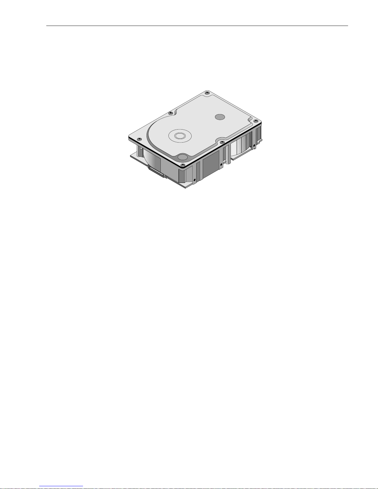
Figure 1. Barracuda 36FC family disc drive . . . . . . . . . . . . . . . . . . . . . . . . . . . . . . . . . . . . . . . . . . . . . . 1
Figure 2. Barracuda 36FC disc drive . . . . . . . . . . . . . . . . . . . . . . . . . . . . . . . . . . . . . . . . . . . . . . . . . . . 5
Figure 3. Typical Barracuda 36FC drive +12V current profile . . . . . . . . . . . . . . . . . . . . . . . . . . . . . . . 20
Figure 4. Typical Barracuda 36FC drive +5V current profile . . . . . . . . . . . . . . . . . . . . . . . . . . . . . . . . 21
Figure 5. DC current and power vs. input/output operations per second . . . . . . . . . . . . . . . . . . . . . . . 22
Figure 6. Locations of PCBA components listed in Table 2 . . . . . . . . . . . . . . . . . . . . . . . . . . . . . . . . . 23
Figure 7. Recommended mounting . . . . . . . . . . . . . . . . . . . . . . . . . . . . . . . . . . . . . . . . . . . . . . . . . . . 25
Figure 8. Mounting configuration dimensions . . . . . . . . . . . . . . . . . . . . . . . . . . . . . . . . . . . . . . . . . . . . 27
Figure 9. Physical interface . . . . . . . . . . . . . . . . . . . . . . . . . . . . . . . . . . . . . . . . . . . . . . . . . . . . . . . . . 31
Figure 10. LED indicator connector . . . . . . . . . . . . . . . . . . . . . . . . . . . . . . . . . . . . . . . . . . . . . . . . . . . . 32
Figure 11. Air flow . . . . . . . . . . . . . . . . . . . . . . . . . . . . . . . . . . . . . . . . . . . . . . . . . . . . . . . . . . . . . . . . . . 33
Figure 12. Physical interface . . . . . . . . . . . . . . . . . . . . . . . . . . . . . . . . . . . . . . . . . . . . . . . . . . . . . . . . . 49
Figure 13. Port bypass circuit physical interconnect . . . . . . . . . . . . . . . . . . . . . . . . . . . . . . . . . . . . . . . 49
Figure 14. FC-AL SCA device connector dimensions . . . . . . . . . . . . . . . . . . . . . . . . . . . . . . . . . . . . . . 50
Figure 15. J6 connector dimensions . . . . . . . . . . . . . . . . . . . . . . . . . . . . . . . . . . . . . . . . . . . . . . . . . . . . 50
Figure 16. FC-AL transmitters and receivers . . . . . . . . . . . . . . . . . . . . . . . . . . . . . . . . . . . . . . . . . . . . . 52
Figure 17. Transmit eye diagram . . . . . . . . . . . . . . . . . . . . . . . . . . . . . . . . . . . . . . . . . . . . . . . . . . . . . . 57
Figure 18. Receive eye diagram . . . . . . . . . . . . . . . . . . . . . . . . . . . . . . . . . . . . . . . . . . . . . . . . . . . . . . . 57
Page 10

Page 11
Barracuda 36FC Product Manual, Rev. B 1
1.0 Scope
This manual describes Seagate Technology®, LLC, Barracuda 36FC (Fibre Channel) disc drives.
Barracuda 36FC drives support the Fibre Channel Arbitrated Loop and SCSI Fibre Channel Protocol specifica-
tions to the extent described in this manual. The Fibre Channel Interface Manual (part num ber 77767496)
describes the ge neral Fibre Chan nel Arbitrated Loop character istics of t his and othe r Seagate Fibre Channel
drives.
Figure 1.
Barracuda 36FC
family disc drive
Page 12

Page 13

Barracuda 36FC Product Manual, Rev. B 3
2.0 Applicable standards and reference documentation
The drive has been developed as a system peripheral to the highest standards of design and construction. The
drive depends upon i ts host equip ment to provide adequ ate power and environment i n order to achieve optimum performance and compli ance with applicable industry and governm ental regulations. Special attention
must be given in the areas of safety, power distribution, shielding, audible noise control, and temperature regulation. In particular, the drive must be secur e ly mo unte d i n o rd er to guara ntee the s pec if ied per for ma nc e char acteristics. Mounting by bottom holes must meet the requirements of Section 8.5.
2.1 Standards
The Barracuda 36FC family complies with Seagate standards as noted in the appropriate sections of this manual and the Seagate Fibre Channel Interface Manual, part number 77767496.
The Barracuda 36FC disc dr i ve is a UL recogni zed componen t per UL1 950, C SA certified to CAN/ CSA C22. 2
No. 950-95, and VDE certified to VDE 0805 and EN60950.
2.1.1 Electromagnetic compatibility
The drive, as delivered, is designed for system integration and installation into a suitable enclosure prior to use.
As such the drive is suppli ed as a subassembly and is not su bject to Subpar t B of Part 15 of the FCC Rules
and Regulations nor the Radio Interference Regulations of the Canadian Department of Communications.
The design characteristics of the drive serve to minimize radiation when installed in an enclosure that provides
reasonable shielding. As such, the drive is capable of meeting the Class B limits of the FCC Rules and Regulations of the Canadian Department of Communications when properly packaged. However, it is the user’s
responsibility to assure that the drive meets the appropriate EMI req uirements in their syst em. Shielded I/O
cables may be required if the e nclosure does not provide ad equate sh ielding. If the I/O c ables are externa l to
the enclosure, shielded cables should be used, with the shields grounded to the enclosure and to the host controller.
2.1.1.1 Electromagnetic susceptibility
As a component assembly, the drive is not required to meet any susceptibility per formance requ irements. It is
the responsibility of tho se integrating the dr ive within their sy stem s to perform thos e tests req uired and design
their system to ensu re that equipment operating in the sam e system as the drive or external to the s ystem
does not adversely affect the pe rformance o f the dr ive. See Section 5.1.1 o n page 13 and Table 1, DC power
requirements, on page 19.
2.1.2 Electromagnetic compliance
Seagate uses an indep endent laborator y to confir m compliance wi th the directives/standar ds for CE Marking
and C-Tick Marking. The drive was tested in a representative system for typical applications. The selected system represents the most popular characteristics for test platforms. The system configurations include:
• 486, Pentium, and PowerPC microprocessors
• 3.5-inch floppy disc drive
• Keyboard
• Monitor/display
• Printer
• External modem
• Mouse
Although the test system with this Seagate model complies with the directives/standards, we cannot guarantee
that all systems will comply. The computer manufacturer or system i ntegrator shall confir m EMC complianc e
and provide the appropriate marking for their product.
Electromagnetic compliance for the European Union
If this model has the CE Marki ng it complies with the European Union requirem ents of the Electromagnetic
Compatibility Direc tive 89/336/EEC o f 03 May 1989 as ame nded by Direct ive 92/31/EE C of 28 Ap r il 1992 an d
Directive 93/68/EEC of 22 July 1993.
Page 14

4 Barracuda 36FC Product Manual, Rev. B
Australian C-Tick
If this model has the C-Tick Markin g it complies with the Australia/New Zea land Standard A S/NZS3548 199 5
and meets the Electro magnetic Compatibility (EMC) Framework requirements of Australia’s Spectrum Management Agency (SMA).
2.2 Reference documents
Barracuda 36FC Installation Guide
Seagate part number: 77767544
Fibre Channel Interface Manual
Seagate part number: 77767496
ANSI Fibre Channel Documents
X3.230-1994 FC Physical and Signaling Interface (FC-PH)
X3.297.1997 FC-PH-2 Fibre Channel Physical and Signaling Interface-2
X3.303.1998 FC-PH-3 Fibre Channel Physical and Signaling Interface-3
X3.272-1996 FC Arbitrated Loop (FC-AL)
X3.269-1996 Fibre Channel Protocol for SCSI (FCP)
NCITS TR-19 Private Loop SCSI Direct Attach (PLDA)
NCITS TR-20 Fabric Loop Attachment (FC-FLA)
SFF-8045 Specification for 40-pin SCA-2 Connector with Parallel Selection.
SFF-8067 Specification for 40-pin SCA-2 Connector with Bidirectional Enclosure Services
Interface.
ANSI Small Computer System Interface (SCSI) Documents
X3.131-1994 (SCSI-2)
X3.270-1996 (SCSI-3) Architecture Model
NCITS 305-199X (SCSI-3) Enclosure Services
30553-001 Specification for Acoustic Test Requirement and Procedures
In case of conflict between this document and any referenced document, this document takes precedence.
Page 15

Barracuda 36FC Product Manual, Rev. B 5
3.0 General description
BarracudaTM 36FC drives combine sof t adjacent layer (SAL) magnetoresistive (MR) heads, par tial respo nse/
maximum likelihood (PRML) read channel electronics, embedded servo technology , and a Fibre Channel interface to provide high performance, hig h capacity data storage for a variety of systems in cluding engineering
workstations, network servers, mainframes, and supercomputers.
Barracuda 36FC dri ves are random access stora ge devices designed to supp or t the Fibre Cha nnel Arbitrate d
Loop (FC-AL) and SCSI Fibre Channe l Protocol as describe d in the ANSI specificatio ns, this document, and
the Fibre C hannel Interface Manual (part number 77767 496 ) which d escr ibes the general i nterface character-
istics of this drive. ST136475FC drives are classified as intelligent peripherals and provide level 2 conformance
(highest level) with the ANSI SCSI-1 standard.
The head and disc as sembly (HDA) is sealed at the factory. Air recirculates withi n the HDA through a nonreplaceable filter to maintain a contamination-free HDA environment.
See Figure 2 for an exploded view of the drive. Never disassemble the HDA. This exploded view is for information only. Do not attempt to service items in the sealed enclosure (heads, media, actuator, etc.) as this requires
special facilities. The drive conta ins no parts replace able by the user and openin g the HDA for any reason
voids your warranty.
Figure 2. Barracuda 36FC disc drive
Barracuda 36FC drives use a dedicated landing zone at the innermost radius of the media to eliminate the possibility of destroying or degrading dat a by landing in th e data zone. The heads au tomatically go to the lan ding
zone when power is removed from the drive.
An automatic shipping lock prevents potential damage to the heads and discs that results from movement during shipping and handl ing. The shipping lock disengages and the head lo ad process begins when power is
applied to the drive.
Barracuda 36FC dr ives decode track 0 location d ata from the ser vo data embedded on each sur face to eliminate mechanical transducer adjustments and related reliability concerns.
The drives also use a high-performance actuator assembly with a low-inertia, balanced, patented, straight arm
design that provides excellent performance with minimal power dissipation.
Page 16

6 Barracuda 36FC Product Manual, Rev. B
3.1 Standard features
Barracuda 36FC drives have the following standard features:
• Integrated dual port FC-AL controller
• Concurrent dual port transfers
• Support for FC arbitrated loop, private and public attachment
• Differential copper FC drivers and receivers
• Downloadable firmware using the FC-AL interface
• 128-deep task set (queue)
• Supports up to 32 initiators
• Drive selection ID and configuration options are set on the FC-AL backpanel or through interface com-
mands. Jumpers are not used on the drive.
• Supports SCSI Enclosure Services through the interface connector
• Fibre Channel worldwide name uniquely identifies the drive and each port
• User-selectable logical block size (512 to 4,096 bytes per logical block)
• Selectable frame sizes from 128 to 2,112 bytes
• Industry standard 3.5-inch low profile form factor dimensions
• Programmable logical block reallocation scheme
• Flawed logical block reallocation at format time
• Programmable auto write and read reallocation
• Reed-Solomon error correction code
• Sealed head and disc assembly (HDA)
• No preventive maintenance or adjustments required
• Dedicated head landing zone
• Automatic shipping lock
• Embedded Grey Code track address to eliminate seek errors
• Self-diagnostics performed at power on
• 1:1 interleave
• Zone bit recording (ZBR)
• Vertical, horizontal, or top down mounting
• Dynamic spindle brake
• 1,024 Kbyte data buffer. See Section 4.5
• Embedded servo design
• Reallocation of defects on command (Post Format)
• Fibre Channel interface transports SCSI protocol
3.2 Media description
The media used on the dr ive has a di ameter of a pproximately 84 mm (approximate ly 3.4 inch es). The aluminum substrate is coate d with a thin film magnet ic material, overcoated wi th a proprietar y protective layer for
improved durability and environmental protection.
3.3 Performance
• Programmable multi-segmentable cache buffer
• 106 Mbytes/sec maximum instantaneous data transfers per port.
• 7,200 RPM spindle; average latency = 4.17 msec
• Command queuing of up to 128 commands
• Background processing of queue
• Supports start and stop commands
• Adaptive seek velocity; improved seek performance
3.4 Reliability
• 1,000,000 hour MTBF
• LSI circuitry
• Balanced low mass rotary voice coil actuator
Page 17

Barracuda 36FC Product Manual, Rev. B 7
• Self-Monitoring Analysis and Reporting Technology (S.M.A.R.T.)
• Dithering
3.5 Unformatted and formatted capacities
Formatted capacity depends on the spare reallocation sectors scheme selected, the number of data tracks per
sparing zone, and the number of alternate sectors (LB As) per sparing zone. The following table shows the
standard OEM model read capacities data. Total LBAs = read capacity data shown below + 1.
Formatted Unformatted
ST136475FC 43D671Fh blocks (36.42 Gbytes with 512 bytes per block) 43.2 Gbytes
Standard OEM models are formatted to 512 bytes per block. You can order other capacities by requesting a different sparing scheme and logical block size.
The sector size is selectable at format time. Users having the necessary equipment may modify the data block
size before issuing a format command and obtain different formatted capacities than those listed.
ST136475FC dr ives use a zone spar ing scheme. The drive is divided into frequency zones with a variable
number of spares in each zone.
3.6 Programmable drive capacity
Using the Mode Select command, the drive can change its capacity to something less than maximum. See the
Mode Select (6) parameter list table in the Fibre Channel Interface Manual, par t number 7767 496. A value of
zero in the Number of Blocks field indica tes that the dr ive will not change the ca pacit y it is curren tly formatted
to have. A number other than zero and less than the maximum number of LBAs in th e Number of Bl ocks field
changes the total drive capacity to the value in the Number of Blocks field. To restore the drive to maxi mum
capacity, enter a value of FFFFFFFF in the Number of Blocks field.
3.7 Factory-installed accesso r ies
OEM standard drives are shipped with the Barracuda 36FC Installation Guide (part number 77767544).
3.8 Factory-installed options
You may order the following items which are incorporated at the m anufacturing facility durin g production or
packaged before shipping. Some of the options available are (not an exhaustive list of possible options):
• Other capacities can be ordered depending on sparing scheme and sector size requested.
• Single-unit shippi ng pack. The drive is nor mally shipped in bulk packaging to provide maximum p rotection
against transit damage. Units shipped individually require additional protection as provided by the single unit
shipping pack. Users planning single unit distribution should specify this option.
• The Barracuda 36FC Installation Guide, part number 77767544, is usually included with each standard OEM
drive shipped, but extra copies may be ordered.
3.9 User-installed accessories
The following accessories are available. All kits may be installed in the field.
• Evaluation kit, part number 73473641.
This kit provides an adapte r car d (“T-card”) to allow cable connectio ns for two FC ports and DC p ower. Two
twin axial cables, 6 feet in length, are included for the input and output connections to the FC interface.
• Single-unit shipping pack.
Page 18

Page 19

Barracuda 36FC Product Manual, Rev. B 9
4.0 Performance characteristics
This section provides detailed information concerning performance-related characteristics and features of Barracuda 36FC drives.
4.1 Internal drive characteristics
ST136475FC
Drive capacity 36.4 ..........................Gbytes (formatted, rounded off value)
Read/write data heads 20
Bytes per track 186,000 ....................Bytes (average, rounded off values)
Bytes per surface 2,184 ........................Mbytes (unformatted, rounded off value)
Tracks per surface (total) 11,721 ......................Tracks (user accessible)
Tracks per inch 12,580 ......................TPI
Peak bits per inch 223 ...........................KBPI
Internal data rate 137-240....................Mbits/sec (variable with zone)
Disc rotation speed 7,200 ........................rpm (+
Avg rotational latency 4.17 ..........................msec
4.2 Seek performance characteristics
See Section 9.5, “FC-AL physical interface” on page 49 and the Fibre Channel Inte rface Manual (part number
77767496) for additional timing details.
4.2.1 Access time
0.5%)
Including controller overhead
(without disconnect)
Read Write
Average Typical
Single track Typical
Full stroke Typical
1. Execution time measured from receipt of the FCP Command to the FCP Response.
2. Assumes no errors and no sector has been relocated.
3. Typical access times are measured under nominal conditions of temperature, voltage, and horizontal orientation as
measured on a representative sample of drives.
4. Access time = controller overhead + average seek time.
Access to data = controller overhead + average seek time + latency time.
3,4
3,4
3,4
7.7 8.4
0.9 1.2
16 17
1, 2
(msec)
4.2.2 Format command execution time for ≥ 512-byte sectors
ST136475FC
Maximum (with verify) 80 minutes
Maximum (without verify) 40 minutes
Page 20

10 Barracuda 36FC Product Manual, Rev. B
4.2.3 General performance characteristics
ST136475FC
Minimum sector interleave 1 to 1
Data buffer to/from disc media (one 512-byte logical block)*
Minimum 16.2 MBytes/sec
Average 25.3 MBytes/sec
Maximum 28.3 MBytes/sec
Fibre Channel Interface maximum instantaneous transfer rate 106 Mbytes/sec* per
port (dual port = 212
Mbytes/sec*)
Logical block sizes
Default is 512-byte data blocks
Variable 512 to 4,096 bytes per sector in n + 4 intervals (n = number
of bytes per sector).
Read/write consecutive sectors on a track
Flaw reallocation performance impact (f or flaws reallocated at format time
using the spare sectors per sparing zone reallocation scheme.)
Overhead time for head switch in sequential mode
Overhead time for one track cylinder switch in sequential mode
Average rotational latency
*Assumes no errors and n o relocated log ical b loc ks. Rate meas ured from th e start of the first logica l
block transfer to or from the host.
Yes
Negligible
1.0 msec
1.1 msec (typical)
4.17 msec
4.3 Start/stop time
If the Motor Start option is disabled, the drive becomes ready within 31 seconds after DC power is applied. If a
recoverable error condition is detected during the start sequence, the drive executes a recovery procedure and
the time to become ready may exceed 31 seconds. Stop time is less than 20 seconds (maximum) from removal
of DC power.
If the Motor Star t option is enabled, the i nternal contr oller accepts th e commands list ed in the Fibre Channel
Interface Manual less than 3 seconds after DC power has been applied. After the Moto r Start co mmand has
been received, the drive becomes ready for normal operations within 25 seconds (excluding the error recovery
procedure). The Motor Start command can also be used to command the drive to stop the spindle.
There is no power control switch on the drive.
4.4 Prefetch/multi-segmented cache control
The drive provides a prefetch (read look-ahe ad) and multi-segmented cache con trol algorithms th at in many
cases can enhance s ystem performance. Cache refers to the drive buffer storage space when it is used in
cache operations. To select this feature, the host sends the Mode Sel ect command wi th the proper values in
the applicable bytes in page 08h. Prefetch and cache operations are indep end ent features from the sta ndp oin t
that each is en abled and disabled ind ependently us ing the Mode Select comm and; however, in actual operation, the prefetch feature overlaps cache operation somewhat as described in sections 4.5.1 and 4.5.2.
All default cache and prefetch mode pa rameter values (Mode Page 08h) for standard OEM versions of this
drive family are given in Table 16.
Page 21

Barracuda 36FC Product Manual, Rev. B 11
4.5 Cache operation
Note.
Refer to the Fibre Channel Interface Manual for more detail concerning the cache bits.
Of the 1,024 kbytes physical buffer space in the d rive, 924 kbytes can be u sed as a cac he. The buffer can be
divided into logical segments (using Mode Select Page 08h, byte 13) from which data is read and to which data
is written.
The drive keeps track of the logical block addresses of the data stored in each segment of the buffer. If the
cache is enabled (see RCD bit in the Fibre Channel Interface Manual), data reques te d by the h ost with a r ea d
command is retr ieved from the buffer, if possible, before any disc access is initia ted. If ca che operation is not
enabled, the buffer (still segmented with the required number of segm ents) is still used, but only a s circular
buffer segments during disc medium read operations (disregarding Prefetch operation for the moment). That is,
the drive does not check in the buffer segments for the requested read data, but goes directly to the medium to
retrieve it. The retrieved data merely passes thr ou gh some buffer segment on the way to the host. On a ca ch e
miss, all data transfers to the host are in accordance with buffer-full ratio rules. On a cache hit, the drive ignores
the buffer-full ratio rules. See the explanation provided with the information about Mode Page 02h (disconnect/
reconnect control) in the Fibre Channel Interface Manual.
The following is a simplified description of the prefetch/cache operation:
Case A
—read command is received and the first logical block is already in the cache:
1. Drive transfers to the initiator the first logical block requested plus all subsequent contiguous logical blocks
that are already in the cache. This data may be in multiple segments.
2. When a requested logica l block is reached that is not in any cache seg ment, the drive fetches it and any
remaining requested logical block addresses fr om the disc and pu ts them in a se gment of the ca che. The
drive transfers the remaining requested log ical blocks from the cache to the host in accordance with the
Mode Select Disconnect/Reconnect parameters, page 02h.
3. If the prefetch feature is enabled, refer to section 4.5.2 for operation from this point.
Case B
—A Read command requests data, and the first logical block is not in any segment of the cache:
1. The drive fetches the requested logic al blocks from the disc and transfers them into a segment, and the n
from there to the host in accordance with the Mode Select Disconnect/Reconnect parameters, page 02h.
2. If the prefetch feature is enabled, refer to section 4.5.2 for operation from this point.
During a prefetch, the drive crosses a cylinde r boundary to fetch data only if the Discontinuit y (DISC) bit is se t
to 1 in bit 4 of byte 2 of the Mode Select parameters page 08h. Default is one for bit 4.
Each cache segment is actually a self-contained circ ular buffer whose length is an integer number of logical
blocks. The wrap-around capability of the individual segments greatly enhances the ca che’s overall perfor-
mance, allowing a wide range of user-selectable configu rations. The drive supports operation of any inte ger
number of segments from 1 to 16. Divide the 924 Kbytes in the buffer by the number of segments to get the
segment size. Default is 3 segments.
Note.
The size of each segment is not repo r ted by Mode Sense c ommand pa ge 08h, bytes 14 and 15. The
value 0XFFFF is always reported regardless of the actual size of the segment. Sending a size specification using the Mode Selec t co mmand (bytes 14 a nd 15) does not set up a new seg ment s ize. If the
STRICT bit in Mode page 00h (byte 2, bit 1) is set to one, the drive responds as it does for any attempt
to change an unchangeable parameter.
4.5.1 Caching write data
Write caching is a wr ite op eration by the dr ive that makes use of a drive buffer storage area where the data t o
be written to the medium is stored whil e the drive p erforms the Write command.
If read caching is enabled (RCD=0), then data written to the medium is retained in the cache to be made available for future read cache hits. The s ame buffer space and segme ntat ion is u sed a s set up for read func tions.
The buffer segmentation scheme is set up or changed independently, having nothing to do with the state of
RCD. When a write co mmand is issued, if RCD=0 , the cache is first checked to see if any logical blocks that
are to be writte n are already stored in the cach e from a previous read or write comman d. If there are, the
respective cache segments are cleared. The new data is cached for subsequent Read commands.
Page 22

12 Barracuda 36FC Product Manual, Rev. B
If the number of write data logical blocks exceed the size of the segment being written into, when the end of the
segment is reached, the data is written into the beginning of the same cache segment, overwriting the data that
was written there at the begin nin g of the operat ion ; however, the drive does not overwrite data that has not yet
been written to the medium.
If write caching is enabled (WCE=1), then the drive may return Good status on a write command after the data
has been transferred into the cache, but before the data has been written to the medium. If an error occurs
while writing the data to the medium, and Good status has already been returned, a deferred error will be generated.
The Synchronize Cache command may be used to force the drive to write all cached write data to the medium.
Upon completion of a Synchronize Cache command, all data received from previous write commands will have
been written to the medium.
Table 16 shows the mode default settings for the drive.
4.5.2 Prefetch operation
If the Prefetch feature is enabled, data in conti guous lo gical blocks on the disc i mmedia tely b eyond that which
was requested by a Read command are retrieved and stored in the buffer for immediate transfer from the buffer
to the host on subsequent Rea d comma nds tha t request th ose log ical blocks (this is tr ue even if cache operation is disabled). Though the pr efetch operation uses the buffer as a cache, finding the reques ted data in the
buffer is a prefetch hit, not a cache operation hit.
To enable Prefetch, us e Mode Select page 08h, byte 12, bit 5 (Disable Read Ahea d - DRA bit). DRA bit = 0
enables prefetch.
Since data that is prefetched replaces data already in som e buffer segments, the host can limit the amoun t of
prefetch data to optimize system performanc e. The Max Prefetch field (bytes 8 and 9) limits the amount of
prefetch. The drive does not use the Prefetch Ceiling field (bytes 10 and 11).
During a prefetch operation, the drive cross es a cy linder bou nda ry to fetch more data only if Mode paramete rs
page 08h, byte 2, bit 4 is set to 1 (Discontinuity--DISC bit).
When prefetch (read look-ahe ad) is enabled (enabled by DRA = 0), it operates under the control of ARLA
(Adaptive Read Look-Ahead). If the host uses software interleave, ARLA enables prefetch of contiguous blocks
from the disc when it sense s that a prefetch hit will l ikely occur, even if two consecutive read operations were
not for physically contiguous blocks of data (e.g. “software interleave”). ARLA disables prefetch when it decides
that a prefetch hit will not likely occur. If the host is not using softwa re interleave, and if two sequential read
operations are not for contiguous blocks of data , ARL A dis ables pre fetch, but as long as s equ enti al read oper ations request contiguous blocks of data, ARLA keeps prefetch enabled.
Page 23

Barracuda 36FC Product Manual, Rev. B 13
5.0 Reliability specifications
The following reliability speci fications assume correc t host and drive operational in terface, including all interface timings, power supply voltages, environmental requirements and drive mounting constraints
Seek error rate:
Read Error Rates
Recovered Data
Unrecovered Data
Miscorrected Data
Interface error rate:
1
Less than 10 errors in 10
Less than 10 errors in 10
Less than 1 sector in 10
Less than 1 sector in 10
Less than 1 error in 10
Less than 1 error in 10
See Section 9.6.4, “Differential PECL input.” on page 57
MTBF: 1,000,000 hours
Service life: 5 years
Preventive maintenance: None required
1. Error rate specified with automatic retries and data correction with ECC enabled and all flaws reallocated.
5.1 Error rates
The error rates stated in this manual assume the following:
• The drive is operated in accordance with thi s manual using DC power as defined in paragraph 6.2, “DC
power requirements.”
• The drive has been formatted with the FC-AL Format command.
• Errors caused by media defects or host system failures are excluded from error rate computations.
• Assume random data.
8
seeks
12
bits transferred (OEM default settings)
15
bits transferred
21
bits transferred
12
bits transferred with minimum receive eye.
14
bits transferred with typical receive eye.
5.1.0.1 Interface errors
An interface error is defin ed as a failure of the receiver on a por t to recover the data as transmitted by the
device port connected to the receiver. The error may be detected as a running disparity error, illegal code, loss
of word sync, or CRC error. The total error rate for a loop of devices is the sum of the indi vidual device error
rates.
5.1.1 Environmental interference
When evaluating systems operation under conditio ns of electromagnetic int erference (EMI), the performance
of the drive within the system is consid ered ac ceptable if t he dri ve does not gene rate an unrec overable condition.
An unrecoverable error, or condition, is defined as one that:
• is not detected and corrected by the drive itself
• is not detected from the error or fault status provided through the drive or FC-AL interface
• is not recovered by normal drive or system recovery procedures without operator intervention
5.1.2 Write errors
Write errors can occur as a result of media defects, environmental interference, or equipm ent malfunction.
Therefore, write errors are not predictable as a function of the number of bits passed.
If an unrecoverable write error occurs beca use of a n equipm ent mal functi on in the dr ive, the error is classi fied
as a failure affecting MTBF. Unrecoverable write errors are thos e that ca nnot be cor rected wi thin two attem pts
at writing the record with a read verify after each attempt (excluding media defects).
5.1.3 Seek errors
A seek error is defined as a failure of the drive to position the heads to the addressed track. There must not be
more than ten recoverable seek errors in 10
drive automatically per forms an error recover y process. If the error r ecovery process fails, a seek posi tioning
8
physical seek operations. After detect ing an i nit ial se ek er ror, the
Page 24

14 Barracuda 36FC Product Manual, Rev. B
error (15h) is repor ted wit h a Medium err or (3h) or Har dware error (4h) repo rt ed in the Sense Key. This is an
unrecoverable seek error. Unrecoverable seek errors are classified as failures for MTBF calculatio ns. Refer to
the Fibre Channel Interface Manual, part number 77767496, for Request Sense information.
5.2 Reliability and service
You can enhanc e the reliability of Ba rracuda 36FC disc drives by ensu ring that the drive receives ade quate
cooling. Section 6.0 provides temperature measurements and se ction 8.4 provides cooling and air flow information which you can use to enhance the service life of the drive.
5.2.1 Mean time between failure (MTBF)
The production disc drive achieves an MTBF of 1,000,000 hours when operated in an environment that
ensures the case temperatures spec ified in Sectio n 6.4.1 are not exceeded. Shor t-ter m excursions up to the
specification limits of th e op erati ng e nvironmen t wi ll not a ffect MTBF p er formanc e. Ope rating th e drive at case
temperatures above these values will adversely affect the drive’s ability to meet specifications. See Section 6.4,
“Environmental limits”.
The MTBF target is specified as device power-on hours (POH) for all drives in service per failure.
The following expression defines MTBF:
MTBF per measurement period = Estimated power-on oper ating hours in the period
Number of drive failures in the period
Estimated power-on operating hours means power-on hours per disc drive times the total number of disc drives
in servic e. Each disc dr ive must have accumulated at least ni ne months of op eration. Data is c alculated on a
rolling average base for a minimum period of six months.
MTBF is based on the following assumptions:
• 8,760 power-on hours per year
• 250 average on/off cycles per year
• Read/seek/write operation during 20% of power-on hours
• Operating at nominal voltages
• System provides adequate cooling to ensure the case temperatures specified in Section 6.4.1 are not
exceeded.
Drive failure means any stoppage or substandard performance caused by drive malfunction.
A S.M.A.R.T. (Self-Monitor ing Analysis and Repor ting Technology) predictive failure indicates that the drive is
deteriorating to an imminent failure and is considered an MTBF hit.
5.2.2 Field failure rate vs time
The expected field failure rate is listed below. Drive utilization will vary. An estimate range of utilization is:
• 720 power-on hours (POH) per month
• 250 on/off cycles per year
• Read/seek/write operation 20% of POH
• System provides adequate cooling to ensure the case temperatures specified in Section 6.4.1 are not
exceeded.
Month Parts per million (PPM)
1 2,364
2 1,422
3 1,403
4 1,391
5 1,317
6 1,255
7 1,162
8+ 1,025
Page 25

Barracuda 36FC Product Manual, Rev. B 15
Failure rate is calculated as follows:
• No system-induced failures counted
• PPM targets include 30% no defect found and handling failures
• Based on 1,000,000 MTBF and 720 POH per month
• Month 1’s rate includes a 300 PPM installation failure
5.2.3 Preventive maintenance
No routine scheduled preventive maintenance is required.
5.2.4 Service life
The drive has a usefu l service life of five years. Depot repair or r eplac eme nt of major parts is perm itt ed d uring
the lifetime.
5.2.5 Service philosophy
Special equipment i s requir ed to repair the dr ive HDA. To achieve the above service l ife, repairs must be performed only at a proper ly equ ipped and s taffed Seagate ser v ice and r epair facili ty. Troubleshooting and repa ir
of PCBs in the field is not recommen ded becaus e of the extensive diagnostic equipm ent required for effective
servicing. There are not spare parts available for this drive. The drive warranty is voided if the HDA is opened.
5.2.6 Service tools
No special tools are requi red for site instal lat ion or recomm ended for site maintenance. Refer to Section 5.2.5.
The depot repair philosophy of the drive precludes the necessity for special tools. Field repair of the drive is not
practical because users cannot purchase individual parts for the drive.
5.2.7 Hot plugging the drive
Inserting and removing the dr ive on the FC-AL will interrupt loop operati on. The interrup tion occurs wh en the
receiver of the next device in the loop must synchronize to a different input signal. FC error detection mechanisms, character sync, running disparity, word sync, and CRC are able to detect any error. Recovery is initiated
based on the type of error.
The disc drive defaults to the FC-AL Moni toring s tate, Pass-through state, when it is powered-on by switching
the power or hot plugged. T he control line to a n optiona l por t bypass circuit (external t o the dr ive), defaults to
the Enable Bypass state. If the bypass circuit is prese nt, the next device in the loop wil l co nti nue to recei ve the
output of the previous device to the newly inserted device. If the bypass circuit is not present, loop operation is
temporarily disrupted until the next device starts receiving the output from the newly inserted device and
regains synchronization to the new input.
The Pass-through state is disabled while the drive performs self test of the FC interface. The control line for an
external port bypass circuit remains in the Enable Bypass state while self test is running. If the bypass circuit is
present, loop operation may continue. If the bypass circuit is not present, loop operation will be halted while the
self test of the FC interface runs.
When the self test completes successfully, the control line to the bypass circuit is disabled and the drive enters
the FC-AL Initializing state. The receiver on the next device in the loop must synchronize to output of the newly
inser ted drive.
If the self-test fails, the control line to the bypass circuit remains in the Enable Bypass state.
Note.
It is the responsibil ity of th e system s inte grator to assu re that no tem perature, ener gy, voltage hazard,
or ESD potential hazard is presented during the hot connect/disconnect operation. Discharge the static
electricity from the drive carrier prior to inserting it into the system.
Caution.
The drive motor must come to a complete stop prior to changing the plane of operation. This time is
required to insure data integrity.
Page 26

16 Barracuda 36FC Product Manual, Rev. B
5.2.8 S.M.A.R.T.
S.M.A.R.T. is an acro nym for Self-Monito ring A nalysis and Reporting Technology. This technol ogy is intended
to recognize conditions tha t indicate imminent d rive failure and is designed to provide sufficient warni ng of a
failure to allow you to back up the data before an actual failure occurs.
Note.
The drive’s firmware monitors speci fic attributes for degradation over time but can’t predict instantaneous drive failures.
Each monitored att r ibute has been s elec ted to moni tor a speci fic set of failure condi tions i n the operati ng performance of the drive and the thresholds are optimized to minimize “false” and “failed” predictions.
Controlling S.M.A.R.T.
The operating mode of S.M.A.R.T. is controlled by the DEXCPT and PERF bits on the Informational Exceptions
Control mode page ( 1Ch). Use th e DEXCPT bit to enable or disable the S.M.A.R.T. feature. Setting the DEXCPT bit disables all S.M.A.R.T . functions. When enabled, S.M.A.R.T. collects on-line data as the drive performs
normal read an d write operations. When the PE RF bit is set, the drive is conside red to be in “On-line Mode
Only” and will not perform off-line functions.
You can measure o ff-line attributes and force the dr ive to save the data by using the Rezero Unit command.
Forcing S.M.A.R.T. resets the timer so that the next scheduled interrupt is in two hours.
You can interrogate the drive through the host to determine the time remaining before the next scheduled measurement and data logging process occurs. To accomplish this, issue a Log Sense command to log page 0x3E.
This allows you to control when S.M.A.R.T. interruptions occur. Forcing S.M.A.R.T. with the RTZ command
resets the timer.
Performance impact
S.M.A.R.T. attr ibute data is saved to the disc so th at the events that caused a predictive failure can be r ecreated. The drive measures and saves parameters onc e every two hours subj ect to an idle per iod on the F C-A L
bus. The process of measur i ng off-li ne att r ibute data a nd saving data to the d isc is unin terr uptable. The m aximum on-line only processing delay is summarized below:
Maximum processing delay
On-line only delay
DEXCPT = 0, PERF = 1
S.M.A.R.T. delay times 30 milliseconds 200 milliseconds
Fully-enabled delay
DEXCPT = 0, PERF = 0
Reporting control
Reporti ng is controll ed by the MRIE b its in the Infor mational E xceptio ns Control mo de page (1C h). Subje ct to
the repor ting me thod, th e firmware will issu e to the host an 01-5Dx x sens e cod e. The erro r code is p reser ved
through bus resets and power cycles.
Determining rate
S.M.A.R.T. monitors the rate at which errors occur and signals a predictive failure if the rate of degraded errors
increases to an unacceptable level. To determine rate, error events are logged and compared to the number of
total operations for a given attribute. The inte r val defines the numbe r of operat ions over which t o measur e the
rate. The counter that keeps track of the current number of operations is referred to as the Interval Counter.
S.M.A.R.T. measur es error rates. All erro rs for each monit ored attribute are recorded. A counter keeps track of
the number of errors for the current interval. This counter is referred to as the Failure Counter.
Error rate is the number of errors per operation. The algorithm that S.M.A.R.T. uses to record rates of error is to
set thresholds for the number of e rrors an d their inte r val. If the numbe r of e rrors exceeds the threshol d before
the interval expires, the error rat e is considered to be unacceptable. If the number of er rors does not exceed
the threshold before the interval expires, the error rate is considered to be acceptable. In either case, the interval and failure counters are reset and the process starts over.
Page 27

Barracuda 36FC Product Manual, Rev. B 17
Predictive failures
S.M.A.R.T. signal s predi ctive failures when the d rive is pe rforming unaccep tably for a period o f time. The f ir mware keeps a running count of the number of times the error rate for each attribute is unacceptable. To accomplish this, a counter is increme nted each time the er ror rate is unaccepta ble and decremented (not to exceed
zero) whenever the error rate is acceptable. If the counter continually increm ents such that it reaches the predictive threshold, a pre dictive failure is signaled. Th is counter is referred to as the Failure Histor y Counter.
There is a separate Failure History Counter for each attribute.
5.2.9 Product warranty
Beginning on the da te of sh ip men t to t he cus tom er an d c onti nuing for a per io d of five years, Seagate warrants
that each product (includ ing componen ts and subass emblies) that fails to function pr operly unde r normal use
due to defect in materials o r workmanship or due to nonc onformance to the applicable s pecifications will be
repaired or replaced, at Sea gate’s option and at no charge to the customer, if returned by customer at customer’s expense to Seagate’s designated facility in accordance wi th Seagate’s warranty procedure. Seagate
will pay for transporting the repair or replacement item to the customer. For more detailed warranty information,
refer to the standard terms and conditions of purchase for Seagate products on your purchase documentation.
The remaining warranty for a particular drive can be determined by calling Seagate Customer Service at
1-800-468-3472. You can also determine remaini ng warranty us i ng the S ea gate web s ite ( www.seagate.com).
The drive serial number is required to determine remaining warranty information.
Shipping
When transporting or shipping a drive, use only a Seagate-approved container. Keep your original box.
Seagate approved containers are easily identified by the Seagate Approved Package label. Shipping a drive in
a non-approved container voids the drive warranty.
Seagate repair centers may refuse receip t of compon ents imp roper ly pa ckaged or obviously damaged in transit. Contact your authorized S eagate distr ibutor to purchase ad ditional boxes. Seagate recommends sh ipping
by an air-ride carrier experienced in handling computer equipment.
Product repair and return information
Seagate customer se rvice centers are the only facilities author ized to service Seagate drives. Seagate does
not sanction any third-par ty repair facilities. Any unauthor ized repair or tampering with the factor y seal voids
the warranty.
Page 28

Page 29

Barracuda 36FC Product Manual, Rev. B 19
6.0 Physical/electrical specifications
This section provides information relating to the physical and electrical characteristics of the drive.
6.1 AC power requirements
None.
6.2 DC power requirements
The voltage and current req uirements for a single dr ive are shown below. Val ues indicated app ly at the dr ive
connector.
Table 1: DC power requirements
ST136475FC
Notes (Amps) (Amps)
Voltage +5V +12V [2]
Regulation [5] ±5% ±5% [2]
Avg idle current DCX
Maximum starting current
(peak DC) DC [3] 0.75 2.63
(peak AC) AC [3] 3.1
Delayed motor start (max) DC [1] [4] 0.55 0.25
Peak operating current:
Typical DCX
Maximum DC [1] 0.75 1.30
Maximum (peak) DC 1.1 2.6
[1] [7] 0.7 0.95
[1] [6] 0.75 1.25
[1] Measured with average reading DC ammete r. Instantaneous +12V current peaks wi ll exceed these val-
ues. Power supply at nominal voltage.
[2] For +12 V, a –10% tolera nc e i s allowed during ini tia l spindle start but must retu rn to ±5% before reaching
7,200 RPM. The ±5% must be maintained after the dr ive signifies that its power-up sequence has been
completed and that the drive is able to accept selection by the host initiator.
[3] See +12V current profile in Figure 3.
[4] This condition occurs when the Motor Star t option is enabled and the drive has not yet received a Star t
Motor command.
[5] See paragraph 6.2.1, “Conducted noise immunity.” Specified voltage tolerance includes r i ppl e, nois e, and
transient response.
[6] Operating condition is defined as random 8 block reads at 208 I/Os per second. Current and power speci-
fied at nominal voltages. Increasing +5 volt supply by +5% increases 5 volt current by < 0.5%. Decreasing
+12 volt supply by 5% increases +12 volt current by 1.4%.
[7] During idle, the dr ive heads are relocated every 60 seconds to a random location within the ban d from
track zero to one-fourth of maximum track.
General DC power requirement notes.
1. Minimum current loadi ng for each supply voltage is not less than 4% of the maximum operating curren t
shown.
2. The +5V and +12V supplies should employ separate ground returns.
3. Where power is provided to multiple drives from a common supply, careful consideration for individual drive
power requirements should be noted. Where multiple units are powered on simultaneously, the peak starting current must be available to each device.
4. Parameters, other than spindle start, are measured after a 10-minute warm up.
Page 30

20 Barracuda 36FC Product Manual, Rev. B
6.2.1 Conducted noise immunity
Noise is specified as a periodi c and random distribution of frequencie s covering a band from DC to 10 MHz.
Maximum allowed noise values given below are peak-to- peak measurements and apply at the drive power
connector.
+5V +12V (with spindle motor not running)
0 to 100 kHz 150mV 150mV
100 kHz to 10 MHz 100mV 100mV
6.2.2 Power sequencing
The drive does not requir e power sequencing. T he drive protects aga inst inadver tent wr iting dur ing power-up
and down.
6.2.3 Current profiles
Figure 3 identifies th e dri ve +12V curren t profile an d Figur e 4 identi fies the d rive +5V cu rrent prof ile. The current during the various times is as shown:
T0 Power is applied to the drive.
T1 Controller self-tes ts are perfor med.
T2 Spindle begins to accelerate under current limiting after performing internal diagnostics.
T3 Spindle is up to speed and the Head-Arm restraint is unlocked.
All times and currents are typical. See Table 1 for maximum current requirements.
Note:
+12 Volt Current during spindle start – Typical Amperes
3.0
2.5
2.0
1.5
Amps
1.0
0.5
0.0
Min. AC
T0 T1 T2 T3 T4
Peak AC Envelope
Peak DC
0.0 2.0 4.0 6.0 10.0 12.0 14.0 16.0
Figure 3. Typical Barracuda 36FC drive +12V current profile
8.0 18.0
TIME (seconds)
Page 31

Barracuda 36FC Product Manual, Rev. B 21
+5 Volt Current during spindle start – Typical Amperes
1.2
1.0
AC component
0.8
0.6
Amps
0.4
0.2
Nominal (average)
DC curve
0.0
T0
T1 T2 T3 T4
0.0 5.0 10.0 15.0 25.0 30.0 35.0 40.0
20.0 45.0
TIME (seconds)
Figure 4. Typical Barracuda 36FC drive +5V current pr o file
Page 32

22 Barracuda 36FC Product Manual, Rev. B
6.3 Power dissipation
To obtain typical operating random read (8 blocks) power dissipation at nominal voltages, refer to Figure 5. The
drive user must decide what number of I/O ope rations constitutes a typica l number of I/O operations for their
installation. To calculate BTUs per h our, multiply watts by 3.4123. Typic al Power dissipation under idle conditions is 14.9 watts (50.8 BTUs per hour).
1.4
1.2
1.0
0.8
Amperes
0.6
0.4
0.2
0.0
0204060
I/Os per Second
Figure 5. DC current and power vs. input/output operations per second
80 100 120
140
16
12
5V A
12V A
Watts
Watts
8
6.4 Environmental limits
Temperatu re an d humidity values experienced by the drive must be such that cond ens ati on doe s n ot o cc ur on
any drive part. A ltitude and atmospher ic pressure specificat ions are referenced to a standa rd day at 58.7°F
(14.8°C). Maximum wet bulb temperature is 82°F (28°C).
6.4.1 Temperature
a. Operating
With cooling designed to mainta in the ca se te mperature s of Table 2, the drive meets all speci fica tions over
a 41°F to 122°F (5°C to 50°C) drive ambient temperature range with a maximum temperature gradient of
36°F (20°C) per hour. The enclosure for the drive should be designed such that the temperatures at the
locations specif ied in Table 2 are not exceeded. Air flow may be needed to achieve these temperature values (see Section 8.4 a nd 8.4.1). Ope ration at case te mperatures ab ove these values may adversely affect
the drives ability to meet specifications.
The MTBF specification for the drive is based on operating in an environment th at ensures that the case
temperatures specified in Table 2 are not exceeded. O ccasiona l excursions t o drive ambi ent tempe ratures
of 122°F (50°C) or 41°F (5°C) may occur with out impact to specified MTB F. Air flow may be needed to
achieve these temperatures (see Section 8.4.1). Continual or sustained operation at case temperatures
above these values may degrade MTBF.
To confirm that the required cooling for the electronics and HDA is provided, place the drive in its final
mechanical configuration , per for m random wr i te/ re ad op erations. Aft er the tem pera tures sta bi lize, measure
the case temperature of the components listed in Table 2 (see note [2]).
The maximum allowable HDA case temperature is 60°C. Operatio n of the dr ive at the ma ximum c ase t emperature is intended for shor t time periods only. Continuous operation at the elevated temperatures will
reduce product reliabili ty.
Page 33

Barracuda 36FC Product Manual, Rev. B 23
Table 2: PCBA and HDA temperatures
Items in
Figure 6
Maximum allowable
case temp erature (°C)
operating
Maximum allowable
case [3] temperatures (°C)
to meet MTBF spec.
HDA [2] 60 45
1 67 52
2 73 58
3 87 72
465 50
Notes.
[1] Section 8.4.1 descr ibes the air-flow patter ns used when gene rating the 1 million hours MTBF guide-
lines in column 2. Air flow was opposite tha t s hown in S ec tio n 8. 4.1. Local air velocity was 0 .92 m/s ec
(180 lfpm). Inlet ai r temperature to the dr ive was 77 °F (25°C), plus 9°F (5°C) temperature rise in the
test enclosure (86°F/30°C ambient local to the drive).
[2] Measure HDA temp at point labeled “HDA” on Figure 6.
[3] PCB mounted integrated circuit case.
b. Non-operating
–40° to 158°F (–40° to 70°C) package ambient w ith a maximum gradient of 36°F (20°C) per hour. This
specification assumes that the drive is packaged in the shipping container designed by Seagate for use with
drive.
HDA Temp.
Check Point
Figure 6. Locations of PCBA components listed in Table 2
1.00
14
2
3
Page 34

24 Barracuda 36FC Product Manual, Rev. B
6.4.2 Relative humidity
The values below assume that no condensation on the drive occurs.
a. Operating
5% to 95% non-condensing relative humidity with a maximum gradient of 10% per hour.
b. Non-operating
5% to 95% non-condensing relative humidity.
6.4.3 Effective altitude (sea level)
a. Operating
–1,000 to +10,000 feet (–305 to +3,048 meters)
b. Non-operating
–1,000 to +40,000 feet (–305 to +12,210 meters)
6.4.4 Shock and vibration
Shock and vibration limits spec ified in this documen t are mea sure d dire ctly on the dr i ve chassis. If the dr ive is
installed in a n enclosu re to whic h the stat ed shock and/o r vibratio n criter ia is applied, resonance s may occur
internally to the enclosure resulting in drive movement in excess of the stated limits. If this situation is apparent,
it may be necessary to modify the enclosure to minimize drive movement.
The limits of sho ck and vibration de fined within this document are speci fied with the drive mounted by any o f
the four methods shown in Figure 7, and in ac cordance wit h the restricti ons of Sectio n 8.5. Orient ation of the
side nearest the LED may be up or down.
6.4.4.1 Shock
a. Operating—normal
The drive, as installed for normal operation, shall operate error free while subjected to intermittent shock not
exceeding 5.0 Gs at a maximum duration of 11 ms ec (half s inewave). Shock may be applied in the X, Y, or
Z axis.
b. Operating—abnormal
Equipment, as installed for normal operation, does not incur physical damage while subjected to inter mittent shock not exceeding 10 Gs at a maximum duration of 11 msec ( half sinewave). Shock occurring a t
abnormal levels may promote degraded operational performance during the abnormal shock period. Specified operational performance will continue when normal operating shock levels resume. Shock may be
applied in the X, Y, or Z axis. Shock is not to be repeated more than two times per second.
c. Non-operating
The limits of non- operating shock shal l appl y to all c onditi ons of h andlin g a nd transpo rtation. This inc ludes
both isolated drives and integrated drives.
The drive subjected to nonrepeti tive shock not exceeding 50 Gs at a maximum duration of 11 msec (half
sinewave) shall not exhibit device damage or performan ce degradati on. Shock may be appl ied in the X, Y,
or Z axis.
The drive subjected to nonrepeti tive shock not exceeding 150 Gs at a maximum duration of 2 msec (half
sinewave) does not exhibit device damage or performance degradation. Sh ock may be applied in the X , Y,
or Z axis.
The drive subjected to nonr epetiti ve shock not exceeding 100 Gs at a maxi mum durati on of 0.5 ms ec (hal f
sinewave) does not exhibit device damage or performance degradation. Sh ock may be applied in the X , Y,
or Z axis.
Page 35

Barracuda 36FC Product Manual, Rev. B 25
d. Packaged
Disc drives shipped as lo ose load ( not pall etized) general fr eight will b e packaged to withs tand drop s from
heights as defined in the table below. For additional details refer to Seagate specifications 30190-001
(under 100 lbs/45 kg) or 30191-001 (over 100 lbs/45 Kg).
Package size Packaged/product weight Drop height
<600 cu in (<9,800 cu cm) Any 60 in (1524 mm)
600-1800 cu in (9,800-19,700 cu cm) 0-20 lb (0 to 9.1 kg) 48 in (1219 mm)
>1800 cu in (>19,700 cu cm) 0-20 lb (0 to 9.1 kg) 42 in (1067 mm)
>600 cu in (>9,800 cu cm) 20-40 lb (9.1 to 18.1 kg) 36 in (914 mm)
Drives packaged in single o r multipacks with a gr oss weight o f 20 pounds (8.95 kg) or less by Seaga te for
general freight shipmen t shall withs tand a drop tes t from 48 in ches (1,070 mm) again st a concre te floor or
equivalent.
Z
Y
X
Figure 7. Recommended mounting
X
Z
Y
Page 36

26 Barracuda 36FC Product Manual, Rev. B
6.4.4.2 Vibration
a. Operating - normal
The drive as installed for normal operation, shall comply with the complete specified performance whil e
subjected to continuous vibration not exceeding
5-22 Hz @ 0.02 inches (0.51 mm) displacement peak to peak
22-350 Hz @ 0.5 G 0 to peak
Vibration may be applied in the X, Y, or Z axis.
b. Operating - abnormal
5-22 Hz @ 0.03 inches (0.76 mm) displacement peak to peak
22-350 Hz @ 0.75 G (X, Y, or Z axis) 0 to peak
c. Non-operating
The limits of non-operating vibration shall apply to all conditions of handling and transportation. This
includes both isolated drives and integrated drives.
The drive shall not incur physical dama ge or degraded performan ce as a resu lt of continuous vi bration not
exceeding
5-22 Hz @ 0.081 inches (2.05 mm) displacement peak to peak
22-350 Hz @ 2.00 G 0 to peak
Vibration may be applied in the X, Y, or Z axis.
6.4.5 Air cleanliness
The drive is designed to operate in a typical office environment with minimal environmental control.
6.4.6 Acoustics
Sound power during idle mode shall be 4.2 bels typical when measured to ISO 7779 specification.
There will not be any discrete tone s more than 10 dB above the masking nois e on typical drives when mea-
sured according to Sea gate specifi cation 30553-00 1. There will no t be any tones more than 2 4 dB above the
masking noise on any drive.
6.4.7 Electromagnetic susceptibility
See Section 2.1.1.1.
Page 37

Barracuda 36FC Product Manual, Rev. B 27
6.5 Mechanical specifications
Refer to Figure 8 for detailed mounting configuration dimensions. See Section 8.5, “Drive mounting.”
Height: 1 .62 in 41.1 mm
Width: 4.000 in 101.6 mm
Depth: 5.75 in 146.05 mm
Weight: 2.2 pounds 0.99 kilograms
B
Motherboard Ref.
P
R[3]
H
1.875–.0051.875–.005
(.809)
[4]
Common centerline
in the horizontal
(X axis) direction
of the drive
Pin 1
J
K
[2]
Low
Profile
Half
Height
N
.136
[1]
F
D
E
L
C
M
Notes:
Mounting holes three on each side, 6-32 UNC.
[1]
Max screw length into side of drive is 0.15 in.
(3.81 mm).
Mounting holes four on bottom, 6-32 UNC.
[2]
Max screw length into bottom of drive is 0.15 in.
(3.81 mm).
Keep-out zone for any components on
[3]
backplane.
Connector is centered on module and flush
[4]
with end of base.
A
Inches Millimeters
5.75
A
–
0.025
4.00
B
–
0.015
1.026
C
max
.620
D
ref
4.000
E
–
0.010
.250
F
+
0.011
—
0.005
3.750
H
–
0.010
2.380
J
–
0.010
1.750
K
–
0.010
0.181
L
+
0.013
—
0.007
1.622
M
+
0.027
—
0.021
1.620
N
–
0.025
.1215
P
max
.1215
R
max
146.05
101.6
26.060
15.748
101.600
6.350
95.25
60.45
44.450
4.590
41.20
41.150
3.080
3.080
– .64
– .381
max
ref
– .25
+ .28
— .12
– .25
– .25
– .50
+ .33
— .18
+ .69
— .53
– .64
max
max
Figure 8. Mounting configuration dimensions
Page 38

Page 39

Barracuda 36FC Product Manual, Rev. B 29
7.0 Defect and error management
The drive, as delivered, complies with this prod uct manual . The read error rates and specifi ed storage cap acities are not dependent upon use of defect management routines by the host (initiator).
Defect and error management in the SCSI protocol involves the drive internal defect/error man agement and
FC-AL system error considerations (errors in communications between the initiator and the drive). T ools for use
in designing a defect/error management plan are b riefly ou tlined in this section. References to other sec tions
are provided when necessary.
7.1 Drive internal defects/errors
During the initial d rive format operati on at the factor y, media defects are identified, tagged as being unusa ble,
and their locations reco rded on the drive primary defects list (referred to as the “P’ list and also as the ETF
defect list). At factory format time, these known defects are also reallocat ed, that is, reassigned to a new place
on the medium and the l ocation listed in the defects reallocation table. The “P” li st is not alter ed after factory
formatting. Locations of defects found and reallocated d uring error r ecovery procedures after drive shipment
are listed in the “G” l ist (defects growth list). Th e “P” and “G” lists may be referenced by the initiator using the
Read Defect Data command.
Details of the SCSI comman ds supported by the drive are desc ribed in the Fibre Channel Inter face Manual.
Also, more information on the drive Error Recovery philosophy is present ed in the Fibre Channel Interface
Manual.
7.2 Drive error recovery procedures
When an error occurs during drive operation, the drive, if programmed to do so, performs error recovery procedures to attempt to recover the data. The error recovery procedures used depend on the options previously set
in the Error Recovery Parameters mode pag e. Error rec overy and defect managem ent may involve using several SCSI commands descr ibed in the Fibre C hann el Interface Manual. The dr ive imple ments selec table error
recovery time limits required in video applications.
The error recovery scheme supported by the drive provides a way to control the total error recovery time for the
entire command in addition to controlling t he r ec overy level for a single LBA. The to tal amo unt of ti me s pe nt i n
error recovery for a command can b e li mi ted us ing the Rec overy Ti me Lim it bytes in the Err or Recover y mode
page. The total amount of time spen t in error recovery for a single LBA can be limited using the Read Retr y
Count or Write Retry Count bytes in the Error Recovery mode page.
The drive firmware error recovery a lgorithms co nsists of 12 levels for read recoveries and 16 levels for write.
Each level may consist of multiple steps, where a step i s defined as a re covery functio n involving a single reread or re-write attem pt. The ma ximum level used by the drive in LBA recovery is determined by the read and
write retry counts.
Table 3 equate s the read and write retr y count with the maximum poss ible recovery time for read and write
recovery of individua l LBA s. The time s given do not i nclude t ime taken to perform r eall ocations. Rea llocati ons
are performed when the ARRE bit (for reads) or AWRE bit (for writes) is one, the RC bit is zero, and the recovery time limit for the command has not yet been met. Time needed to perform reallocation is not counted
against the recovery time limit.
Page 40

30 Barracuda 36FC Product Manual, Rev. B
When the RC bit is one, reallocation s are disabled even if the ARRE or AWRE bits are one. The drive will still
perform data recovery actions within the limits defined by the Read Retr y Count, Write Retry Count, and
Recovery Time Limit parameters. However, the drive does not report any unrecovered errors.
Table 3: Read and write retry count maximum recovery times
Maximum recovery time per
Read retry count
0 108.68 0 91.96
1 125.4 1 117.04
2 426.36 2 125.4
3 459.8 3 150.48
4 526.68 4 300.96
5 593.56 5 359.48
6 677.16 6 593.56
7 802.56 7 618.64
8 836 8 660.44
9 911.24 9 685.52
10 2,371.24 10 1,735.68
11 (default) 3,422.04 11 1,760.76
1
LBA (cumulative, msec)
Write retry count
12 1,769.12
13 1,794.2
14 1,944.68
15 2,003.2
Maximum recovery time per
1
LBA (cumulative, msec)
[1] Setting these retr y co unts to a value below the default setting could result i n degradation of t he unrecov-
ered error rate. For example, suppose the read/wr ite recovery page has the RC bit = 0, th e read retry
count set to 4, and the recovery ti me limit set to 450. A 4-block read command can take up to 526.68
msec recovery time for each block and a maximum of 4 50 msec recovery for all four blocks. If either o f
these limits is reached and a block has not yet been recovered, the command wil l end with Che ck Condition status and an unrecoverable read error will be reported.
7.3 FC-AL system errors
Information on the rep orting of ope rational errors or faults across the int erface is given in the Fibre Channel
Interface Manual. The FCP Respons e r eturns information to the ho st a bou t numer ous k ind s of error s or faults.
The Receive Diagnostic Results reports the results of diagnostic operations performed by the drive.
Status returned by the drive to the initiator is described in the Fibre Channel Interface Manual. Status reporting
plays a role in systems error management and its use in that respect is described in sections where the various
commands are discussed.
Page 41

Barracuda 36FC Product Manual, Rev. B 31
8.0 Installation
Barracuda 36FC disc drive installation is a plug-and-play process. There are no jumpers, switches, or terminators on the drive. Simply plug the dr ive into the ho st’s 40-pin Fibre Channel backpanel conn ector (F C-SCA)
no cables are required. See Section 9.5 for additional information about this connector.
Use the FC-AL interface to select drive ID and all option configurations for devices on the loop.
If multiple devices are on the same FC-AL and physical addresses are used, set the device selection IDs (SEL
IDs) on the backpanel so that no two devices have the same selection ID. This is called the hard assigned arbitrated loop physical address (AL_PA). There are 125 AL_PAs available (see Table 22 on page 55). If you set
the AL_PA on the backpanel to any value other than 0, the device plugged into the backpanel’s SCA connector
inherits this AL_PA. In the event you don’t successfully assign unique hard addresses (and therefore have
duplicate select ion IDs as si gne d to t wo or mo r e devices), the FC- A L gen erate s a mess age ind ic ati ng t his c ondition. If you set the AL_PA on the backpanel to a value of 0, the system issues a unique soft-assigned physical
address automatically.
Loop initialization i s the process used to verif y or obtain an address. The loop initialization pro cess is performed when power is applied to the drive, when a device is added or removed from the Fibre Channel loop, or
when a device times out attempting to win arbitration.
• Set all option selec tions in the connector pr ior to applying power to the dr ive. If you change options after
applying power to the drive, recycle the drive power to activate the new settings.
• It is not necess ar y to low-level format th is dr ive. The d rive is shippe d fro m the factor y low-level formatted in
512-byte logical blocks. You need to reformat the drive only if you want to select a different logical block size.
—
8.1 Drive ID/option selection
All drive options are ma de thr oug h th e i nte rface connector ( J1) . Table 19 on page 51 provides the pi n des criptions for the 40-pin Fibre Channel single connector (J1).
8.2 LED connections
A connector, J6, is provided on the printed c ircu it bo ar d asse mbly (P CBA) to pr ovide port bypass, drive active,
and drive fault LED connections (see Figure 10 on pa ge 32). See Sections 9.5.7, 9. 5.8, and 9.5.9 for descri ptions of LED functions.
J6
Figure 9. Physical interface
Page 42

32 Barracuda 36FC Product Manual, Rev. B
Drive
Front
Pin 1
J6
Reserved
Port A Bypass LED [1]
Port B Bypass LED [1]
Fault LED [1]
Reserved
Active LED [2]
Reserved
+5V
Active LED [1]
Ground [3]
[1] The drive has a 2.2K ohm resistor in series with thi s LED dri ver. Tie the minus side of an
external high-efficien cy LED (i.e., 2ma) to this pin. Connec t the plus side of the LED to
+5V.
[2] An external current-li miting resi stor is requ ired when conn ecting an LE D to this pi n. The
minus side of the resistor/LED combination is connected to this pin. Connect the plus side
to +5V.
[3] Jumper storage location (across pins 2 and 4).
Figure 10. LED indicator connector
8.2.1 J6 connector requirements
Recommended mating connector part number: Berg receptacle, 6-position, Berg part number 690-006.
8.3 Drive orientation
The drive may be mounted in any o rientation. All drive perform ance characterizations, however, have been
done with the drive in horizontal (discs level) and vertical (drive on its side) orientations, which are the two preferred mounting orientations.
8.4 Cooling
Cabinet cooling must be des igned by th e custo mer so that the ambien t temperatu re immedi ately s urroundin g
the drive will not exceed temperature c onditions specified in Section 6.4.1, “Temperature.” Specific consideration should be given to make sure adequate air circulation is present around the printed circuit board (PCB) to
meet the requirements of Section 6.4.1, “Temperature.”
Page 43

Barracuda 36FC Product Manual, Rev. B 33
8.4.1 Air flow
The rack, cabinet, or drawer environment for the drive must provide heat removal from the electronic s and
head and disc assembly (HDA). You should confirm that adequate heat removal is provided using the temperature measurement guidelines described in Section 6.4.1.
Forced air flow may be required to keep temp eratures at or be low the s pecified case te mpe ratures of Table 2,
in which case the drive should be oriented, or air flow directed, so that the least amount of air flow resistance is
created while pr oviding air flow to the el ectronics and HDA. Also, the shor test possible path b etween the air
inlet and exit should be c hosen to min imize the travel length of a ir heate d by the dr ive and oth er he at sourc es
within the rack, cabinet, or drawer environment.
If forced air is determined to be necessa r y, possible air-flow patterns are shown in Figure 11. T he air-flow patterns are created by one or more fans, either forcing or drawing air as shown in the illustrations. Conduction,
convection, or other forced air-flow patter ns are acceptable a s long as the temperatu re measurement guidelines of Section 6.4.1 are met.
Above unit
Under unit
Above unit
Under unit
Figure 11. Air flow
Note. Air flows in the direction shown (back to front)
or in reverse direction (front to back)
Note. Air flows in the direction shown or
in reverse direction (side to side)
8.5 Drive mounting
Mount the drive using the bottom or side mounting holes. If you mount the drive using the bottom holes, ensure
that you do not physically distort the drive by attempting to mount it on a stiff, non-flat surface.
The allowable mounting surface stiffness is 80 lb/in (14.0 N/mm). The following equation and paragraph define
the allowable mounting surface stiffness:
where K is the mounting s urface stiffness (units in lb/in or N/mm) and X is the ou t-of-plane surface disto rtion
(units in inches or millim eters). The ou t-of-plane distor tion (X) i s deter mined by defini ng a plane wi th three of
the four mounting points fixed and evaluating the out-of-plane deflection of the four th mounting point when a
known force (F) is applied to the fourth point.
Note.
Before mounting the drive in any kind of 3.5-inch to 5.25-inch adapter frame, verify with Seagate Tech-
K x X = F < 15lb = 67N
Page 44

34 Barracuda 36FC Product Manual, Rev. B
nology that the drive can meet the shock and vibration s pecifications given herein while mounted i n
such an adapter frame. Adap ter frames that are available may not have a mechanical structure capable of mounting the drive so that it can meet the shock and vibration specifications listed in this manual.
8.6 Grounding
Signal ground (PCBA) and HDA ground are connecte d together in the drive and cannot be separate d by the
user. The equipment in which the drive is moun ted i s co nnec te d dire ct ly to th e HDA and PCBA wi th n o el ectrically isolating shock mounts. If it is desired for the system chassis to not be connected to the HDA/PCBA
ground, the systems integrator or user must provide a nonconductive (electr ically isol ating) method of mou nting the drive in the host equipment.
Increased radiated emissions may result if you do not provide the maximum surface area ground connection
between system ground and drive ground. This is the system designer’s and integrator’s responsibility.
Page 45

Barracuda 36FC Product Manual, Rev. B 35
9.0 Interface requirements
This section partially describes the interface requirements as implemented on ST136475FC drives. Additional
information is provided in the Fibre Channel Interface Manual (part number 77767496).
9.1 FC-AL features
This section lists the Fibre Channel-specific features supported by Barracuda 36FC drives.
9.1.1 Fibre Channel link service frames
Table 4 lists the link services supported by Barracuda 36FC drives.
Table 4: Link services supported
Type of frame Link ser v ice
Basic link service frames Abort Sequence (ABTS)
Basic link service reply frames Basic_Accept (BA_ACC)
Basic_Reject (BA_RJT)
Extended link service frames N_Port Login (PLOGI)
Fabric Login (FLOGI)
Logout (LOGO)
Process Login (PRLI)
Process Logout (PRLO)
Read Link Status (RLS)
Fabric Address Notification (FAN)
Port Discovery (PDISC)
Address Discov ery (ADISC)
Third-party Process Logout (TRPLO)
Extended link service reply frames Accept (ACC)
Link Service Reject (LS_RJT)
Fibre Channel Services Register FC-4 Types (RFT_ID)
9.1.2 Fibre Channel task management functions
Table 5 lists the Fibr e C hannel SCSI Fibre Chann el Pr oto co l (F C S CSI F CP) task management func ti ons supported.
Table 5: Fibre Channel SCSI FCP task management functions
Task name Supported
Terminate task No
Clear ACA Yes
Target reset Yes
Clear task set Yes
Abort task set Yes
9.1.3 Fibre Channel task management responses
Table 6 lists the FC SCSI FCP response codes returned for task management functions supported.
Table 6: FC SCSI FCP response codes
Function name Response code
Function complete 00
Function not supported 04
Function reject 05
Page 46

36 Barracuda 36FC Product Manual, Rev. B
9.1.4 Fibre Channel port login
Table 7 identifies the required content of the N_Port Login (PLOGI) payload from an initiator.
T a b le 7: N_Port login (PLOGI) payload
Bytes
0-15 03 00 00 00 09 09 BB BB CF XX FS FS XX XX XX XX Common
16-31 XXXXXXXXPNPNPNPNPNPNPNPNNNNNNNNN
32-35 NN NN NN NN
36-47 XXXXXXXXXXXXXXXXXXXXXXXXClass 1
48-51 XX XX XX XX
52-63 XXXXXXXXXXXXXXXXXXXXXXXXClass 2
64-67 XX XX XX XX
68-79 SOSOIC IC XXXXFSFSXXCSXXXXClass 3
80-83 OS OS XX XX
84-95 XXXXXXXXXXXXXXXXXXXXXXXXReserved
96-99 XX XX XX XX
100-111 XXXXXXXXXXXXXXXXXXXXXXXXVendor
112-115 XX XX XX XX Version
X Indicates a four-bit (hex) field is not checked.
x Indicates a single bit is not checked.
BB BB-Credit. This field is not checked. The FC-AL drive uses BB-Credit of zero (0).
CF Common features. This binary field selects the common features requested by the initiator login.
MSB Continuously increasing offset Must = 1
Random relative offset Not checked. Port Login Accept will return a 0—not supported.
Valid vers ion level x
N_Port/F_Port Must = 0, N_Port
Alternate credit model Must = 1
Other bits reserved xxx XX
FS Receive buffer field size. The FS field in the common and Class 3 parameters is checked for the range 128 < FS < 2,112 and a
multiple of four bytes. For multiple frame sequences, all frames but the last frame of the sequence must be this size. Only the
receive buffer field size in the Class 3 parameters is used.
PN Port name (initiator’s)—saved with the login parameters. If a change of the port name/AL_PA address association is detected dur-
ing a Port DISCovery, and implicit logout occurs and the initiator returns a LS_RJT.
NN Node name. The node name is not checked or saved by the drive.
SO Service options Class 3 only.
MSB Class valid Must = 1
Intermix x
Stacked connection req. xx
Sequential delivery x
Other bits reserved xxx XX
IC Initiator control
MSB XID reassign xx
Proc Assc 10 or 11 causes the login to be rejected. Other values are accepted.
Other bits XXX
CS Concurrent sequences Must be a value greater than 0.
OS Open sequences per exchange Must be a value greater than 0.
Page 47

Barracuda 36FC Product Manual, Rev. B 37
9.1.5 Fibre Channel port login accept
Table 8 identifies the N_Port Login access payload values.
Table 8: N_Port Login Accept (ACC) payload
Bytes
0-15 02 00 00 00 09 09 00 00 88 00 FS FS 00 FF 00 01 Common
16-31 000001F420PP002037UIUIUI20000020
32-35 37 UI UI UI
36-47 000000000000000000000000Class 1
48-51 00 00 00 00
52-63 000000000000000000000000Class 2
64-67 00 00 00 00
68-79 800000000000FSFS00FF0000Class 3
80-83 00 01 00 00
84-95 000000000000000000000000Reserved
96-99 00 00 00 00
100-111 000000000000000000000000Vendor 112-115 00 00 00 00 Version
FS Recei ve buffer field size . The drive returns and u se s the rec eive buffer size from the N_Port Login Class 3 rec eive
buffer.
UI Unique identifier. This 24-bit field is uniquely assigned to the drive. This same UI appears in the Port Name and
Node Name fields.
PP Port identifier field.
01 P_LOGI received on Port A.
02 P_LOGI received on Por t B.
9.1.6 Fibre Channel Process Login
Table 9 lists the process login payload data.
T a b le 9: Process Login (PLRI) payload
Bytes
0-15 20 10 00 14 08 00 20 00 XX XX XX XX XX XX XX XX
16-19 00000022
XX Indicates fields that are not used.
9.1.7 Fibre Channel Process Login Accept
Table 10 lists Barracuda 36FC process login accept payload data.
Table 10: Process Login Accept (ACC) payload
Bytes
0-15 02 10 00 14 08 00 21 00 00 00 00 00 00 00 00 00
16-31 00000012
Page 48

38 Barracuda 36FC Product Manual, Rev. B
9.1.8 Fibre Channel fabric login
Table 11 lists the fabric login payload from the drive.
Table 11: Fabric Login (FLOGI) payload
Bytes
0-15 04 00 00 00 09 09 00 00 08 00 08 40 00 00 00 00 Common
16-31 000002F420PP002037UIUIUI02000020
32-35 37 UI UI UI
36-47 000000000000000000000000Class 1
48-51 00 00 00 00
52-63 000000000000000000000000Class 2
64-67 00 00 00 00
68-79 800000000000084000000000Class 3
80-83 00 00 00 00
84-95 000000000000000000000000Reserved
96-99 00 00 00 00
100-111 000000000000000000000000Vendor 112-115 00 00 00 00 Version
UI Unique identifier. This 24-bit field is uniquely assigned to the drive. This same UI appears in the Port Name and Node Name
fields.
PP Port identifier field.
01 FLOGI originated on Port A.
02 FLOGI originated on Port B.
Page 49

Barracuda 36FC Product Manual, Rev. B 39
9.1.9 Fibre Channel fabric accept login
Table 11 lists the required content of the Fabric Login Accept (ACC) payload from the fabric.
Table 12: Fabric Login Accept (ACC) payload
Bytes
0-15 02 00 00 00 09 09 BB BB CF XX FS FS R_ A_ T0 V_ Common
16-31 E_D_T0 V_PNPNPNPNPNPNPNPNNNNNNNNN
32-35 NN NN NN NN
36-47 XXXXXXXXXXXXXXXXXXXXXXXXClass 1
48-51 XX XX XX XX
52-63 XXXXXXXXXXXXXXXXXXXXXXXXClass 2
64-67 XX XX XX XX
68-79 SOSOxx xx XXXXFSFSXXxx XXXXClass 3
80-83 OS OS XX XX
84-95 XXXXXXXXXXXXXXXXXXXXXXXXReserved
96-99 XX XX XX XX
100-111 XXXXXXXXXXXXXXXXXXXXXXXXVendor 112-115 XX XX XX XX Version
X Indicates a four-bit (hex) field is not checked.
x Indicates a single bit is not checked.
BB BB-Credit. This field is not checked. The FC-AL drive uses BB-Credit of zero (0).
CF Common features. This binary field selects the common features requested by the fabric login.
MSB Continuously increasing offset x
Random relative offset x
Valid versi on level x
N_Port/F_Port Must = 1, F_Port
Alternate credit model Must = 1
Other bits reserved xxx XX
FS Receive buff er field size. The FS field in the common and Class 3 parameters is checked for the range 128 < FS < 2,112 and a
multiple of four bytes. The receive buff er field size in the Class 3 parameters is used. The drive uses the lower FS of Fabric Login
Accept or N_Port Login when sending frames to an initiator.
PN Port Name. The fabric port name is saved with the login parameters. If a change of the port name is detected during a FAN, an
implicit logout occurs and a LS_RJT is returned to the fabric.
NN Node Name. The drive does not check or save the node name.
SO Service Options—Class 3 only.
MSB Class valid Must = 1
Intermix x
Stacked connection req. xx
Sequential delivery Must = 1
Other bits reserved xxx XX
Page 50

40 Barracuda 36FC Product Manual, Rev. B
9.1.10 Fibre Channel Arbitrated Loop options
Table 13 lists the FC-AL options supported by Barracuda 36FC drives.
Table 13: FC-AL options supported
Option Supported
OPEN Half Duplex Accepted from another device.
OPEN Full Duplex Sent to open another device.
Accepted from another device.
Private Loop Yes
Public Loop Yes
Old Port State No
Loop Position Yes
Loop Position Report Yes
9.2 Dual port support
ST136475FC drives have two independent FC-AL ports. These ports may be connected on independent loops
or on the same loop. Port A and Port B may be connected in any order or combination.
• If both ports are connected on independent loops and hard addressing is used, the drive interface address is
selected through the interface connector, both ports will seek the same loop address. If no conflict, bot h
ports will have the same loop address.
• If both por ts are con nec ted in th e sa me l oop and h ar d add ress i ng is used , at least one por t wi ll attempt taking a soft address to prevent an address conflict.
Note.
When a Barracuda 36FC drive is connected in loops with previous Seagate FC drive products:
Barracuda 4LP FC (ST32171FC, ST34371FC, and ST34571FC)
Barracuda 9FC (ST19171FC)
Cheetah 4LP FC (ST34501FC)
Cheetah 9FC (ST19101FC)
the connection of Port A a nd B for thes e p roduc ts must follow the requirements in thei r product manuals.
Subject to buffer availability, the Barracuda 36FC drives support:
• Concurrent por t transfers—The drive su ppor ts re ceiving transfers on both po r ts at t he same ti me when th e
ports are on independent loops.
• Full duplex—The drive su pports sending F CP_Data, FCP_RSP, FCP_XFR_RDY and ELS transfers while
receiving frames on both ports.
Page 51

Barracuda 36FC Product Manual, Rev. B 41
9.3 SCSI commands supported
Table 14 lists the SCSI commands that ST136475FC drives support.
T a b le 14: Supported command s
Command code Supported Command name
00h Y Test unit ready
01h Y Rezero unit
03h Y Request sense
Y Extended sense
Y Field pointer bytes
Y Actual retry count bytes
04h Y Format unit [9.3.1]
NBlock format
Y Bytes from Index
Y Physical sector format
N DPRY bit supported
Y DCRT bit supported
Y STPF bit supported
Y IP bit supported
Y DSP bit supported
Y IMMED bit supported
N VS (vendor specific)
07h Y Reassign blocks
08h Y Read
0Ah Y Write
0Bh Y Seek
12h Y Inquiry
Y Vital product data page (00h)
Y Unit serial number page (80h)
Y Implemented operating def. page (81h)
Y Firmware numbers page (C0h)
Y Date code page (C1h)
Y Jumper settings page (C2h)
Y Device behavior page (C3h)
15h Y Mode select (same pages as Mode Sense command shown below) [3]
16h Y Reserve
Y 3rd party reserved
N Extent r eservation
17h Y Release
18h N Copy
1Ah Y Mode sense
Y Unit attention page (00h)
Y Error recovery page (01h)
Y Disconnect/reconnect control (page 02h) DTDC and DIMM not used
Y Format page (03h)
Y Rigid disc drive geometry page (04h)
Page 52

42 Barracuda 36FC Product Manual, Rev. B
T a b le 14: Supported command s
(continued)
Command code Supported Command name
Y Verify error recov ery page (07h)
Y Caching parameters page (08h)
Y Control mode page (0Ah)
N Notch and partition page (0Ch)
N Xor control page (10h)
Y Fibre Channel Interface control page (19h)
Y Power control page (1Ah)
Y Information exceptions control page (1Ch)
1Bh Y Start unit/stop unit (spindle ceases to rotate)
1Ch Y Receive diagnostic results
Y Supported diagnostics pages (00h)
Y Translate page (40h)
Y Enclosure services page
1Dh Y Send diagnostics page
Y Supported diagnostics page (00h)
Y Translate page (40h)
25h Y Read capacity
28h Y Read extended
Y Disable page out
Y Force unit access
N Relative address
2Ah Y Write extended
Y Disable page out
Y Force unit access
N Relative address
2Bh Y Seek extended
2Eh Y Write and verify
Y Disable page out
Y Byte check
N Relative address
2Fh Y Verify
Y Disable page out
Y Byte check
N Relative address
30h N Search d ata high
31h N Search d ata equal
32h N Search d ata low
33h N Set limits
34h N Prefetch
35h Y Synchronize cache
36h N Lock-unlock-cache
37h Y Read defect data
39h N Compare
3Ah N Copy and verify
Page 53

Barracuda 36FC Product Manual, Rev. B 43
T a b le 14: Supported command s
(continued)
Command code Supported Command name
3Bh Y Write buffer
Y Write combined header and data mode (0)
Y Write data mode (2)
N Download microcode mode (4)
Y Download microcode and save modes (5)
N Download microcode with offsets mode (6)
Y Download microcode with offsets and save mode (7)
Y Firmware download option [2]
3Ch Y Read buffer
Y Read combined header and data mode (0)
Y Read data mode (2)
Y Read descriptor mode (3)
3Eh Y Read long
3Fh Y Write long
40h Y Change definition
41h Y Write same
N PBdata
NLBdata
42-4Bh N Not used
4Ch Y Log Select
N DU bit
YDS bit
YTSD bit
NETC bit
NTMC bit
NLP bit
4Dh Y Log Sense
Y Cache statistics page (37h)
Y Non-medium error page (06h)
Y Pages supported list (00h)
Y Power-on time page (3Eh)
Y Read error counter page (03h)
Y S.M.A.R.T. status log page (2Fh)
Y S.M.A.R.T. attribute log page (30h)
Y Verify error counter page (05h )
Y Write error counter page (02h)
4E-4Fh N Not used
50h N XD wri te
51h N XP write
52h N XD read
53-54h N Not used
55h Y Mode Select (10) [3]
Y Capacity programming
56h Y Reserved (10)
Page 54

44 Barracuda 36FC Product Manual, Rev. B
T a b le 14: Supported command s
Command code Supported Command name
57h Y Released (10)
58-59h N Not used
5Ah Y Mode Sense (10) [3]
5B-5Dh N Not used
5E Y Persistent reserve in
5F Y Persistent reserve out
60-7Fh N Not used
80h N XD write extended
81h N Rebuild
82h N Regenerate
83-8Fh N Not used
C0-DFh N Not used
EO-FFh N Not used
(continued)
Y 3rd party reserve
N Extent r eservation
[1] Barracuda 36FC drives can format to any multiple of four bytes per logical block in the range 512 to 4,096
bytes.
Warning.
[2]
Power loss durin g flash programming can re sult i n fir m ware corr upti on. Th is us ually makes th e
drive inoperable.
[3] Reference Mode Sense command 1Ah for mode pages supported.
Page 55

Barracuda 36FC Product Manual, Rev. B 45
9.3.1 Inquiry data
Table 15 lists th e Inquir y com mand data th at the dr ive should retur n to the i nitiator per the format given in the
Fibre Channel Interface Manual.
T a ble 15:
Bytes Data (hex)
0-15 00 00 02** 22 8B 00 PP 0A 53 45 41 47 41 54 45 20 Vendor ID
16-31 [53 54 31 33 36 34 37 35 46 43] 20 20 20 20 20 20 Product ID
32-47 R# R# R# R# S# S# S# S# S# S# S# S# 00 00 00 00
48-63 00 00 00 00 00 00 00 00 00 00 00 00 00 00 00 00
64-79 00 00 00 00 00 00 00 00 00 00 00 00 00 00 00 00
80-95 00 00 00 00 00 00 00 00 00 00 00 00 00 00 00 00
96-111 00 43 6F 70 79 72 69 67 68 74 20 28 63 29 20 31* *Copyright
112-127 39* 39* 39* 20 53 65 61 67 61 74 65 20 41 6C 6C 20 notice
128-143 72 69 67 68 74 73 20 72 65 73 65 72 76 65 64 20
* Copyright year (changes with actual year).
** 02 = SCSI-2 implemented with some SCSI-3 features (default).
PP 50 = Inquiry data for an Inquiry command received on Port A.
70 = Inquiry data for an Inquiry command received on Port B.
R# Four ASCII digits representing the last four digits of the product firmware version number.
S# Eight ASCII digits representing the eight digits of the product serial number.
[ ] Bytes 16 through 25 reflect drive model (ST136475FC shown).
Barracuda 36FC
inquiry data (ST136475FC data shown)
9.3.2 Mode Sense data
The Mode Sense command provides a way for the drive to report i ts operating parameters to the ini tiator. The
drive maintains four sets of mode parameters:
1. Default values
Default values are hard-coded in the drive firmware stor ed in flash E-PROM (nonvolatile memor y) on the
drive’s PCB. These default values can be changed only by downloading a complete set of new firmware
into the flash E-PROM. An in itiator c an reque st and recei ve from the dri ve a list of default values and use
those in a Mode Select comma nd to set up new current and saved values, where the values are changeable.
2. Saved values
Saved values are stored on the dri ve’s media using a Mode Selec t com mand. On ly pa rameter values that
are allowed to be changed can be changed by this method. Parameters in the saved values list that are not
changeable by the Mode Select command get their values from default values storage.
When power is applied to the drive, it takes saved values from the media and stores them as current values
in volatile memory. It is not possible to change the current values (or the saved values) with a Mode Select
command before the drive achieves operating speed and is “ready.” An attempt to do so results in a “Check
Condition” status.
On drives requiri ng unique saved values, the required un ique saved values are stored i nto the saved values storage location on the me dia prior to shippin g the drive. Some dr ives may have unique fir m ware wit h
unique default values also.
On standard OEM dri ves, the saved values are taken from the default values list and stored into the saved
values storage location on the media prior to shipping.
3. Current values
Current values are volatile values being used by the drive to control its operation. A Mode Select command
can be used to change the values identifi ed as changeable values. Orig inally, current values are installed
from saved or default values after a power on reset, hard reset, or Bus Device Reset message.
Page 56

46 Barracuda 36FC Product Manual, Rev. B
4. Changeable values
Changeable values form a bit mask, stored in nonvolatile memory, that dictates which of the current values
and saved values can be changed by a Mode Select command. A one (1) indicates the value can be
changed. A zero (0) in dicates the value is not changeable. For example, in Table 16 , refer to Mode page
81, in the row entitled “CHG.” These are hex numbers representing the ch ang eable values for Mode page
81. Note in columns 5 and 6 (bytes 04 and 05), there is 00h which indicates that in bytes 04 and 05 none of
the bits are changea ble. Note also th at bytes 06, 07, and 09 are not changeable, because those fi eld s are
all zeros. In byte 02, hex value FF equates to the binary pattern 11111111. If there is a zero in any bit position in the field, it means that bit is not changeable. Since all of the bits in byte 02 are ones, all of these bits
are changeable.
The changeable values list can only be changed by downloading new firmware into the flash E-PROM.
Note.
Because there are of ten several different versions of drive control firmware in the total po pulation of
drives in the field, the Mode Sens e values given in the following tables may not exactly match those of
some drives.
The following tables list the values of the data bytes returned by the drive in response to the Mode Sense command pages for SCSI implementation (see the Fibre Chan nel Interface Manual).
Definitions:
DEF = Default value. Standard OEM drives are shipped configured this way.
CHG = Changeable bits; indicates if default value is changeable.
Page 57

Barracuda 36FC Product Manual, Rev. B 47
Table 16: Mode Sense data default and changeable values for ST136475FC drives
ST136475FC
Bytes
00 01 02 03 04 05 06 07 08 09 10 11 12 13 14 15 16 17 18 19 20 21 22 23
Mode
Sense
A7 00 10 08 04 3D 67 20 00 00 02 00
Header
<------------------------------------------------ Mode sense pages data ------------------------------------------------>
DEF
81 0A C0 0B E8 00 00 00 0F 00 FF FF
CHG 81 0A FF FF 00 00 00 00 FF 00 FF FF
DEF 82 0E 80 80 00 00 00 00 00 00 01 A6 00 00 00 00
CHG 82 0E FF FF 00 00 00 00 00 00 FF FF 00 00 00 00
DEF 83 16 2A F8 00 00 00 10 00 00 01 30 02 00 00 01 00 30 00 34 40 00 00 00
CHG
83 16 00 00 00 00 00 00 00 00 00 00 00 00 00 00 00 00 00 00 00 00 00 00
DEF 84 16 00 2D C9 14 00 00 00 00 00 00 00 00 00 00 00 00 00 00 1C 27 00 00
CHG
84 16 00 00 00 00 00 00 00 00 00 00 00 00 00 00 00 00 00 00 00 00 00 00
DEF 87 0A 00 0B E8 00 00 00 00 00 FF FF
CHG 87 0A 0F FF 00 00 00 00 00 00 FF FF
DEF 88 12 14 00 FF FF 00 00 FF FF FF FF 80 03 00 00 00 00 00 00
CHG 88 12 B5 00 00 00 FF FF FF FF 00 00 A0 FF 00 00 00 00 00 00
DEF 8A 0A 02 00 00 00 00 00 00 00 00 00
CHG 8A 0A 03 F1 08 00 00 00 00 00 00 00
DEF 99 06 00 00 00 00 00 00
CHG 99 06 00 7F 01 00 00 00
DEF 9A 0A 00 03 00 00 00 01 00 00 00 04
CHG 9A 0A 00 03 00 00 00 00 00 00 00 00
DEF 9C 0A 00 00 00 00 00 00 00 00 00 01
CHG 9C 0A 8D 0F FF FF FF FF FF FF FF FF
DEF 80 02 00 00
CHG 80 02 37 40
<--- Read capacity data --->
04 3D 67 1F 00 00 02 00
Page 58

48 Barracuda 36FC Product Manual, Rev. B
9.4 Miscellaneous operating features and conditions
Table 17 lists var ious features and con ditio ns. A “Y” in the support colum n indi cates the feature or con dition is
supported. An “N” in the support column indicates the feature or condition is not supported.
T a b l e 17: Miscella neo us fe atur es
Supported Feature or condition
Y FC-AL selective reset
Y Automatic contingent allegiance
N Asynchronous event notifi cat ion
N Synchronized (locked) spindle operation
Y Segmented caching
N Zero latency read
Y Queue tagging (up to 128 queue tags supported)
Y Deferred error handling
Y Parameter rounding (controlled by Round bit in Mode Select page 0)
Y Reporting actual retry count in Extended Sense bytes 15, 16, and 17
N Adaptive caching
Y SMP = 1 in Mode Select command needed to save RPL and rotational offset bytes
T a b l e 18: Miscella neo us status
Supported Status
Y Good
Y Check condition
Y Condition met/good
YBusy
Y Intermediate/good
Y Intermediate/condition met/good
Y Reservation conflict
Y Task set full
YACA active
Y ACA active, faulted initiator
Page 59

Barracuda 36FC Product Manual, Rev. B 49
9.5 FC-AL physical interface
Figure 12 shows the locatio n of the J1 Fibre Channel s in gle conne ction attachment (FC-S CA) a nd th e J 6 c onnector. Figure 14 provides the dimensions of the FC- SCA. Figure 15 provides the dimen sions of the J6 connector.
Details of the physical, elec trical, and logic al characterist ics are provided within this section. The ope rational
aspects of Seagate’s Fibre Channel drives are provided in the Fibre Channel Interface Manual..
J6
Figure 12. Physica l inter face
9.5.1 Physical characteristics
This section defines physical interface connector.
9.5.1.1 Physical description
FIbre Channel drives may be connected in a loop together or with other compa tible FC-AL devices. A maximum of 127 devices m ay have addresses; however, one of th e addresses is rese rved for a fabric por t switch
device. This means 126 addresses are available for FC-AL devices. More FC-AL compatible devices may
physically reside on the loop, but they will not be functi onal because they would not be able to obtain valid
addresses.
Port bypass circuits (P BCs) allow devices to be ins er ted into unpopula ted locat ions or removed from the loop
with loop operation re covery after a bri ef interruptio n. These PBCs are located externa l to the FC-AL device.
Figure 13 shows the relationship between the PBC and FC-AL device.
Port Bypass
Circuit
From Previous
Port Bypass
Circuit N–1
Drive
MUX
To Next
Drive
Port Bypass
Circuit N+1
Drive N–1
Figure 13. P ort bypa ss circuit physical interconnect
Select
SerialInSerial
Out
Drive N
Drive N+1
Page 60

50 Barracuda 36FC Product Manual, Rev. B
9.5.2 Connector requirements
Recommended mating SCA part number:
Part description Positions Part number Features
AMP Vertical (SCA sequence) 40 787317-1
Berg 40 71781
Methode 40 512-220-91-101N
Molex 40 717431040
With polarization
With polarization
With polarization
With polarization
The FC-AL SCA device connector is illustrated in Figure 14. The J6 connector is illustrated in Figure 15.
1.618 ± .003 in
(41.1 ± 0.08 mm)
Pin 20
Pin 40
.64 in
(16.24 mm)
1.28 in
(32.47 mm)
1.618 ± .003 in
(41.10 ± 0.08 mm)
1.492 ± .009 in
(37.90 ± 0.24 mm)
Mating end Housing
.05 in
(1.27 mm)
typ.
.025 in (0.635 mm)
Contact (typ.)
Pin 1
Pin 21
0.264+.007 in
(6.71+0.18 mm)
(–0.25 mm)
Figure 14. FC-AL SCA device connector dimensions
–.010 in
0.197 ± .003 in
(5.00 ± .08 mm)
0.226 in
(6.50 mm)
0.106 ± .010 in
(2.70 ± 0.25 mm)
2 places
min.
0.394 ± .004 in
(10.0 ± 0.10 mm)
0.039 in
(0.75 mm)
0.051 ± .006 in
(1.30 ± 0.16 mm)
min.
0.024 in
(0.60 mm)
0.079 ± .010 in
(2.00 ± .25 mm)
0.060 ± .010 in
(1.52 ± 0.25 mm)
min.
(initial point
of contact)
2 places
.079
(2 mm)
Figure 15. J6 connector dimensions
.787
(19.99 mm)
.079 (2 mm)
J6
.708
(17.983 mm)
Page 61

Barracuda 36FC Product Manual, Rev. B 51
9.5.3 Electrical description
Fibre Channel drives use the FC-SCA connector for:
• DC power
• FC-AL interface
• Drive select (device identification)
• Option selection
• Enclosure Services interface
This 40-pin connector is designed to plug directly into a backpanel. External cables are not required.
9.5.4 Pin descriptions
This section provides a pin-out of the FC-SCA and a description of the functions provided by the pins.
Table 19: FC-SCA pin descriptions
Pin Signal name Signal type Pin Signal name Signal type
1* -EN bypass port A TTL output 21 12 Volts charge
2* 12 Volts 22 Ground
3* 12 Volts 23 Ground
4* 12 Volts 24* +Port A_in Diff. PECL input pair
5* -Parallel ESI 25* -Port A_in
6* Ground
7* Active LED out Open collector out 27* +Port B_in Diff. PECL input pair
8* Reserved 28* -Port B_in
9* Start_1 TTL input 29 Ground
10* Start_2 TTL input 30* +Port A_out Diff PECL output pair
11* -EN bypass po rt B TTL output 31* -Port A_out
12* SEL_6 TTL input/output 32 Ground
13* SEL_5 TTL input/output 33* +Port B_out Diff PECL output pair
14* SEL_4 TTL input 34* -Port B_out
15* SEL_3 TTL input/output 35 Ground
16* Fault LED out Open collector out 36 SEL_2 TTL input/output
17* Reserved NC 37 SEL_1 TTL input/output
18* Reserved NC 38 SEL_0 TTL input/output
19* 5 Volts 39 Reserved NC
20 * 5 Volts 40 5 Volts c harge
[9.3.1]
26 Ground
*Short pins in mating backpanel connector.
[1] This pin may be connected t o external logic to detect the presenc e of the drive. The dri ve connects this
pin to the common ground.
Page 62

52 Barracuda 36FC Product Manual, Rev. B
9.5.5 FC-AL transmitters and receivers
A typical FC-AL differential copper transmitter and receiver pair is shown in Figure 16. The receiver is required
to provide the AC coupling to eliminate ground shift noise.
68
TX
Transmitter
TY
150
Figure 16. FC-AL transmitters and receivers
150
68
Differential
Transfer Medium
.01µf
150
.01µf
RX
Receiver
RY
9.5.6 Power
Power is supplied through the FC-SCA with support for +5 volts and + 12 volts. All of the voltage pins in the
drive connector are the same length.
Four 12 volt pins provide +12 volt power to the drive. The current return for the +12 volt power supply is through
the common ground p ins. The supply current and retur n current must be distributed as evenly as possible
among the pins. The maximum current typically occurs while the drive motor is starting.
Three 5 volt pins provide logic power to the drive. The current return for the +5 volt power supply is through the
common ground pins. Distribute supply and return current as evenly as possible among the voltage and ground
pins.
The mating connector pins use shorter contacts to achieve power surge reductions and to aid in “hot plugging”
the drives. There are longer voltage contacts in the connector to enable the drive filter capacitors to charge.
Current to the drive through the long charg e pin s is li mi ted by the syst em in which the d ri ve operates. Three of
the +12 volt pins are shorter to allow capacitive pre-charging through the longer +12 volt charge pin. Tw o of the
+5 volt pins are shorter to allow capacitive precharging through the longer +5 volt charge pin.
9.5.7 Fault LED Out
The Fault LED Out signal is driven by the drive when:
• the drive detects failure of both ports
• the drive detects an internal failure
• the drive receives the appropriate fault LED command from the host
The Fault LED Out signal is designed to pull down the cathode of an LED. The anode is attached to the proper
+5 volt supply through a n appropriate current-l imiting resistor. The LED and the current-li miting resistor are
external to the drive.
9.5.8 Active LED Out
The Active LED Out signal is driven by the drive as indicated in Table 20.
T a b le 20: Active LED Out conditions
Normal command activity LED status
Spun down and no activity Slow blink (20% on and 80% off a 2 sec cycle)
Spun down and activity (command executing) On
Spun up and no activity On
Spun up and activity (command executing) Off
Spinning up or down Blinks steadily (50% on and 50% off)
Format in progress, each cylinder change Toggles on/off
Page 63

Barracuda 36FC Product Manual, Rev. B 53
The Active LED Out signal is designed to pull down the cathode of an LED. The anode is attached to the proper
+5 volt supply through an approp riate current limiting resisto r. The LED and the current limiting r esistor are
external to the drive.
9.5.9 Enable port bypass signals
The – Enable Bypass Port A (– EN BYP Port A ) and – Enable Bypass Port B (– EN BYP Port B) signals control
the port bypass circuits (PBC) located external to the disc drive. The PBC allows a loop to remain functional in
the event of a drive failure or removal. When these signal s are ac tive, low, the PBC bypasses the drive on the
associated por t. When an Enable Bypass s ignal is active, the correspo nding Port Bypass LED signal in c onnector J1 is dri ven low by the disc drive. A pull down resistor, 1K, located with the PBC s hould be used to
insure the bypass is enabled if the disc drive is not installed.
The Enable Bypass signal is active under failing conditions within the drive, on detection of the Loop Port
Bypass primitive sequence, or on removal of the drive. In the bypass state the drive continues to receive on the
inbound fibre. Enable Bypass may be deactivated by detection of a Loop Port Enable primiti ve seque nc e if th e
drive has completed self-test and a hardware failure is not present.
Failure modes detected by the disc drive that will enable bypass include:
• Transmitter/receiver wrap test failure
• Loss of receive clock
• Loss of transmission clock
• Drive interface hardware error
9.5.10 Motor start controls
The drive’s motor is started accor ding to the Star t_1 and Star t_2 signals descr ibed in Table 21. The state of
these signals can be wired into the backplane socket or driven by logic on the backplane.
Table 21: Motor start control signals
Case Start_2 Start_1 Motor spin function
1 Low Low Motor spins up at D C power on.
2 High Low Motor spins up only when SCSI Start command is received.
3 Low High M ot or sp ins up a fter a delay of 12 sec ond s ti mes the modulo 8 va lue of
the numeric SEL ID of the drive from DC power on.
4 High High The drive will not spin up.
9.5.11 SEL_6 through SEL_0 ID lines
The SEL_6 through SEL_0 ID lines de termi ne dr ive address, and, op tionally, for an Enclosure Servic es Interface. When the Parallel ESI line is high, the enclosure backpanel must provide address information on the SEL
line. Refer to table 22 for a mapping of SEL to FC-AL p hysical addresses (AL_ PA) . You can thin k of the SEL
lines as the equivalent of a backpanel logic plug. T he dr ives does not provid e pull up res istors on th ese lines.
The backpanel is required to provide high and low inputs to th e SEL_ID lines per the spe cifi cation s in table 23
on page 56 .
Note.
Table 22 gives AL_PA values for each SEL value. The first entr y in the table is SEL_ID 00. The last
entry is SEL_ID 7D. SEL_ID 7E is AL_PA 00 which is not valid for an NL_Port, so is not included in the
table. Also, SEL_ID 7Fh does map to a valid AL_PA; however, this value signals the drive that physical
addresses are not b eing ass igned u sing the SEL li nes an d that a “soft” address will be deter mined by
FC-AL loop initialization.
When the Parallel ESI line is low, the enclosure backpanel logic switches to ESI mode i f supported. There are
two modes of ESI, seven bits of enclosure status and a bidirec tional mode. ESI support and the mode ar e
determined by the dri ve using a discovery pr ocess. Refer to the Fibre Chan nel Inter face Manual for a descrip tion of ES I operation.
Page 64

54 Barracuda 36FC Product Manual, Rev. B
9.5.11.1 Parallel Enclosure Services Interface (ESI)
The parallel ESI l ine is an output from the drive. This li ne provides the enclosure with an indi cation of the
present function of the SEL lines. A hi gh level, the default state, indi cates the dri ve requires addr ess in formation on the SEL lines. A low level indicates the dr ive is attempti ng an ES I transfer. The enclosure may not support ESI on any or all drive locations. It may only support the address function. Support of ESI is discovered by
the drive. Refer to the Fibre Channel Interface Manual for a description of ESI operations.
Page 65

Barracuda 36FC Product Manual, Rev. B 55
T a b le 22: Arbitrated loop ph ysic al ad dres s (AL_PA) values
AL_PA
(hex)
SEL ID
(hex)
Setting
(dec)
AL_PA
(hex)
SEL ID
(hex)
Setting
(dec)
AL_PA
(hex)
SEL ID
(hex)
Setting
(dec)
EF 00 00 A3 2B 43 4D 56 86
E8 01 01 9F 2C 44 4C 57 87
E4 02 02 9E 2D 45 4B 58 88
E2 03 03 9D 2E 46 4A 59 89
E1 04 04 9B 2F 47 49 5A 90
E0 05 05 98 30 48 47 5B 91
DC 06 06 97 31 49 46 5C 92
DA 07 07 90 32 50 45 5D 93
D9 08 08 8F 33 51 43 5E 94
D6 09 09 88 34 52 3c 5F 95
D5 0A 10 84 35 53 3A 60 96
D4 0B 11 82 36 54 39 61 97
D3 0C 12 81 37 55 36 62 98
D2 0D 13 80 38 56 35 63 99
D1 0E 14 7C 39 57 34 64 100
CE 0F 15 7A 3A 58 33 65 101
CD 10 16 79 3B 59 32 66 102
CC 11 17 76 3C 60 31 67 103
CB 12 18 75 3D 61 2E 68 104
CA 13 19 74 3E 62 2D 69 105
C9 14 20 73 3F 63 2C 6A 106
C7 15 21 72 40 64 2B 6B 107
C6 16 22 71 41 65 2A 6C 108
C5 17 23 6E 42 66 29 6D 109
C3 18 24 6D 43 67 27 6E 110
BC 19 25 6C 44 68 26 6F 111
BA 1A 26 6B 45 69 25 70 112
B9 1B 27 6A 46 70 23 71 113
B6 1C 28 69 47 71 1F 72 114
B5 1D 29 67 48 72 1E 73 115
B4 1E 30 66 49 73 1D 74 116
B3 1F 31 65 4A 74 1B 75 117
B2 20 32 63 4B 75 18 76 118
B1 21 33 5C 4C 76 17 77 119
AE 22 34 5A 4D 77 10 78 120
AD 23 35 59 4E 78 0F 79 121
AC 24 36 56 4F 79 08 7A 122
AB 25 37 55 50 80 04 7B 123
AA 26 38 54 51 81 02 7C 124
A9 27 39 53 52 82 01 7D 125
A7 28 40 52 53 83
A6 29 41 51 54 84
A5 2A 42 4E 55 85
Page 66

56 Barracuda 36FC Product Manual, Rev. B
9.6 Signal characteristics
This section desc ribes the electrical signal cha rac ter i sti c s o f the drive’s input and output signals. See Table 19
on page 51 for signal type and signal name information.
9.6.1 TTL input characteristics
Table 23 provides the TTL characteristics.
T a b le 23: TTL char acte ristics
State Voltage Current
Input high 1.9 < V
Input low -0.5V < V
Output high (-EN Bypass A, B) 2.4 < V
Output low (-EN Bypass A, B) V
Output high (-Par all el ESI) 2.4 V
VOH > 0.9V
Output low (-Parallel ESI) 0 < V
Output high (all other outputs) 2.4 V
VOH > 0.9V
Output low (all other outputs) 0 < V
< 5.5V IIH = ±500nA max.
IH
< 0.9V IOL = ±500nA max.
IL
< 5.25V IOH < -3mA
OH
< 0.5V IOL < 3mA
OL
< V
CC
OH
CC
< .45V IOL < 2.4mA
OL
< V
CC
OH
CC
< .45V IOL < 1.6mA
OL
IOH < -2.4mA
I
< -500µA
OH
IOH < -1.6mA
I
< -500µA
OH
9.6.2 LED driver signals
Fault and Active LED signals are located in the FC-SCA connector (J1) and through the indicator connector
(J6). See Table 24 for the output characteristics of the LED drive signals.
T a b l e 24: LED drive signal
State Current drive available Output voltage
LED off, high 0 < IOH < 100µA
LED on, low I
< -30 mA 0 < VOL < 0.8V
OL
9.6.3 Differential PECL output
The serial PECL output signal voltage characteristics are provided in T able 25. The outputs are not AC coupled
in order to deliver maximum signa l without r ise and fall time degradation . You must AC couple the receiver to
isolate potentially different DC characteristics of the outputs and the receiver.
Table 25: Differential PECL output characteristics
Description Parameter Notes
Serial output voltage swing 300 < V
< 650 mV Centered at 1.32V
out
Page 67

Barracuda 36FC Product Manual, Rev. B 57
Figure 17 provides the data output valid eye diagram relative to the bit cell time.
941 ps
Vout (mv)
800 ps
Figure 17. Transmit eye diagram
9.6.4 Differential PECL input
The serial PECL input signal voltage characteristics are provided in Table 26.
Table 26: Differential PECL input characteristics
Description Parameter Notes
Serial input voltage swing 200mV < V
< 1300 mV AC coupled
in
Figure 18 provides the d ata valid eye diagram for typical and mi nimum requirements to recover data at the
specified interface error rate. The inputs are AC coupled on the drive.
941 ps
Vin (mv)
659 ps
376 ps
Figure 18. Receive eye diagram
Typical
Minimum
Page 68

Page 69

Barracuda 36FC Product Manual, Rev. B 59
10.0 Seagate Technology support services
Online Services
Internet
www.seagate.com
hours daily by e-mail for your disc or tape questions.
Presales Support:
Disc: http://www.seagate.com/support/email/email_presales.html or DiscPresales@Seagate.com.
Tape: http://www.seagate.com/support/email/email_tape_presales.html or
Tape_Sales_Support@Seagate.com.
Technical Support:
Disc: http://www.seagate.com/support/email/email_disc_support.html or DiscSupport@Seagate.com.
Tape: http://www.seagate.com/support/email/email_tape_support.html or TapeSupport@Seagate.com.
Server Appliance: http://www.seagate.com/support/email/email_nas_support.html or
NAS_Support@Seagate.com.
Reseller Marketplace
Reseller Marketplace is the storage industry’s first collaborative, e-commerce marketplace offering res ellers
the fastest, most efficient online purcha sing process for Seagate storage so lutions. The Reseller Marketplace
at http://marketplace.seaga te.com, an exclusive service for US resellers participatin g in the Seagate Partner
Program (SPP), is designed to str eamline the purc hasing proces s of Seagate solutio ns and provide unprec edented value to Seagate’s resellers through real-ti me pricin g and availability, fast and easy compari son shopping, and seamless integration with key distributors for a one-stop shopping experience.
for information about Sea gate products and ser vices. Worldwide suppor t is available 24
For support, questions and comments: http://reseller.seagate.com/benefits/T1.html or 1-877-271-3285 (tollfree) 9
SeaBOARD
products and is available 24 hours daily . Set your communications software to eight data bits, no parity and one
stop bit (8-N-1).
. to 7 P.M. (eastern time) Mon day through Friday.
A.M
®
is a computer bulletin board sy st em tha t co ntai ns information about Seagate disc and tape drive
Automated Services
SeaFONE® (1-800-SEAGATE)
help service s. Using a touch-tone phone, you can fin d answers to service ph one numbers, commonly a sked
questions, troubleshooting tips and specifications for disc dri ves and tape drives 24 hours daily. International
callers can reach this service by dialing +1-405-936-1234.
SeaFAX
support information by return FAX 24 hours daily. This service is available worldwide.
®
is Seagate’s automated FAX delivery system. Using a touch-tone phone, you can obtain tech nical
is Seagate’s toll-free number (1-800-732- 4283) to access our a utomated self-
Presales Support
Presales Support
Our Presales Suppor t staff can he lp you determine whic h Seagate products are bes t suited for your specific
application or computer system.
Disc: 1-877-271-3285; Tape: 1-800-626-6637; Server Appliance: 1-800-732-4283.
Online Tape Purchases
US customers can purc hase Seagate data cartri dges, tape supplies, accessories, and selec t Seagate tape
drive products 24 hours daily at http://buytape.seagate.com.
Page 70

60 Barracuda 36FC Product Manual, Rev. B
Technical Support
If you need help installing your drive, consult your dealer. Dealers are familiar with their unique system configurations and can help you with system confl icts and other tec hnica l issues. If you need add ition al help, you can
talk to a Seagate tec hnical sup por t specia list. Before callin g, note your sy stem configurat ion and dr ive model
number (ST####).
SeaTDD™ (+1-405-936-1 687)
comments 24 hours daily and exchange messages with a technical support specialist from 8:00
12:15
. and 1:30 P.M. to 6:00 P.M. (central time) Monday through Friday.
P.M
is a telecommuni cations device for the deaf (TDD) . You can sen d questio ns or
. to
A.M
Customer Service (CSO)
Warranty Service
Seagate offers worldwide customer supp or t for Seagate drives. Seagate direct OEM, Distri bution and System
Integrator customers should contact their Seagate service center representative for warranty information.
Other customers should contact their place of purchase.
Authorized Service Center s
If you live outside the US, you can contact an Authorized Service Center for service.
USA/Canada/Latin America Support Services
Presales Support
Call Center Toll-free Direct dial FAX
Disc: 1-877-271-3285 +405-936-1210 +1-405-936-1683
Tape: 1-800-626-6637 +1-714-641-2500 +1-714-641-2410
Server Appliance: 1-800-732-4283 +1-405-936-1234 +1-405-936-1683
Technical Support (SeaFONE)
1-800-SEAGATE or +1-405-936-1234 (for specific product phone number)
FAX: Disc: +1-405-936-1685; Tape and Server Appliance: +1-405-936-1683
SeaFAX
SeaTDD
SeaBOARD
1-800-SEAGATE
+1-405-936-1687
Disc: +1-405-936-1600; Tape: +1-405-936-1630
Warranty Service
Call Center Toll-free Direct dial FAX / Internet
USA 1-800-468-3472 +1-405-949-7758 +1-405-949-6740
Mexico and Latin America — +1-405-949-7758 +1-405-949-6738
Canada
Memofix* 1-800-636-6349 +1-905-660-4936 or +1-905-660-4951
http://www.memofix.com
Adtech* 1-800-624-9857 +1-905-812-8099 or +1-905-812-7807
http://www.adtech1.com
Brazil
MA Informatica* — +55-21-516-6649 +55-21-223-3156
e-mail: sgt_cso@gbl.com.br
*Authorized Service Centers
Page 71

Barracuda 36FC Product Manual, Rev. B 61
European Support Services
For European customer support, dial the toll-free number for your specific country for presales support, technical support, SeaFAX and warranty service.
If your country is not liste d here, dial our Eu ropea n call c enter at +31- 20-3 16-7222 from 8 :30
. to 5:00 P.M.
A.M
(European central time) Mon day through Friday. The European call cen ter is lo ca ted i n A ms ter dam , The Ne therlands.
Call Center
Austria 0 800-20 12 90
Belgium 0 800-74 876
Denmark 80 88 12 66
France 0 800-90 90 52
Germany 0 800-182 6831
Ireland 1 800-55 21 22
Italy 800-790695
Netherlands 0 800-732 4283
Norway 800-113 91
Poland 00 800-311 12 38
Spain 900-98 31 24
Sweden 0 207 90 073
Switzerland 0 800-83 84 11
Turkey 00 800-31 92 91 40
United Kingdom 0 800-783 5177
SeaBOARD
Germany +49-89-1409331
Fax Services—All European Countries
Presales/Technical Support/Warranty Service 31-20-653-3513
Africa/Middle East Support Services
For presales, technical suppor t, warranty service and FAX services in Africa and the Middle East, dial our
European call ce nter at +31- 20-316- 7222 fr om 8:3 0
. to 5:00 P.M. (European central ti me) Monday throug h
A.M
Friday, or send a FAX to +31-20-653-3513. The Eu ropean call center is lo cated in Amsterdam, The Netherlands.
Asia/Pacific Support Services
For Asia/Pacific presales and technical suppor t, dial the toll-free number for your specific co untry. The Asia/
Pacific toll-free numbers are available from 6:00
ern time) and 4:00
. to 4:00 P.M. (Singapore time ) Monday through Friday. If your country is not listed here,
A.M
direct dial one of our technical support locations.
Call Center Toll-free Direct dial FAX
Australia 1800-14-7201 +61-2-9725-3366 +61-2-9725-4052
Hong Kong 800-90-0474 — +852-2368 7173
Indonesia 001-803-1-003-2165 ——
Japan ——+81-3-5462-2979
Singapore 800-1101-150 +65-488-7584 +65-488-7528
Taiwan — +886-2-2514-2237 +886-2-2715-2923
Thailand 001-800-11-0032165 ——
Warranty Service
Call Center Toll-free Direct dial FAX
Asia/Pacific and Australia — +65-485-3595 +65-488-7503
Japan — +81-3-5462-2904 +81-3-5462-2979
. to 10:45 A.M., and 12:00 P.M. to 6:00 P.M. (Australian east-
A.M
Page 72

Page 73

Barracuda 36FC Product Manual, Rev. B 63
Index
Numerics
12 volt
pins 52
3rd party reserve command 44
5 volt pins 52
A
Abort Sequence (ABTS) 35
abort task set function 35
AC coupling 52
AC power requirements 19
ACA active status 48
ACA active, faulted initiator status 48
Accept (ACC) 35
acoustics 26
active LED Out signal 52
Actual retry count bytes command 41
actuator 6
assembly design 5
adaptive caching 48
Address Discovery (ADISC) 35
addresses 49
air cleanliness 26
air flow 22, 33
illustrated 33
air inlet 33
Alternate credit model 36, 39
altitude 24
ambient 23
ambient temperature 22, 32
ANSI documents
fibre channel 4
SCSI 4
arbitrated loop physical address (AL_PA) 31
arbitration 31
asynchronous event notification 48
audible noise 3
auto write and read reallocation
programmable 6
automatic contingent allegiance 48
average idle current 19
average rotational latency 9
B
backpanel 51
backplane 53
basic link service frames 35
Basic_Accept (BA_ ACC) 35
Basic_Reject (BA_RJT) 35
BB 36, 39
BB-Credit 36, 39
Block format command 41
buffer
data 6
space 11
busy status 48
bypass circuit 15
Byte check command 42
Bytes from Index command 41
bytes per surface 9
bytes per track 9
C
cache operation 11
cache segments 11
Cache statistics page 43
Caching parameters page (08h) command 42
caching write data 11
Canadian Department of Communications 3
capacity
formatted 7
unformatted 7, 9
Capacity programming 43
case temperature 22
CF 36, 39
Change definition command 43
character sync 15
charge pins 52
check condition status 48
Class 3 parameters 36, 39
class B limit 3
Class valid 36, 39
clear ACA function 35
clear task set function 35
commands supported 41
Common features 36, 39
Compare command 42
Concurrent sequences 36
condensation 24
condition met/good status 48
connector
illustrated 50
requirements 50
continuous vibration 26
Continuously increasing offset 36, 39
Control mode page (0Ah) command 42
cooling 32
Copy and verify command 42
Copy command 41
CRC 15
error 13
CS 36
Current profiles 20
customer service 17
D
data block size
modifing the 7
data buffer to/from disc media 10
data heads
Page 74

64 Barracuda 36FC Product Manual, Rev. B
read/write 9
data rate
internal 9
data transfer rate 10
data valid eye 57
Date code page command 41
DC power 51
requirements 19
DCRT bit 41
defect and error management 29
deferred error handling 48
description 5
Device behavior page 41
device selection IDs 31
devices 31
differential PECL input 57
dimensions 27
Disable page out command 42
disc rotation speed 9
Disconnect/reconnect control (page 02h) command
41
Download microcode and save modes (5) 43
Download microcode mode (4) 43
Download microcode with offsets and save mode (7)
43
Download microcode with offsets mode (6) 43
DPRY bit 41
drive 26
drive active LED connection 31
drive characteristics 9
drive fault LED connection 31
drive ID 31
drive ID/option select headers 31
drive mounting 27, 33
drive orientation 32
drive select 51
driver signals 56
drivers and receivers 6
DS bit 43
DSP bit 41
DU bit 43
dual port support 40
E
electrical
description of connector 51
signal characteristics 56
specifications 19
electromagnetic compatibility 3
electromagnetic interference (EMI) 13
electromagnetic susceptibility 26
EMI 13
EMI requirements 3
enable bypass
port A 53
port B 53
signal 53
state 15
Enclosure Services interface 51
Enclosure services page command 42
environment 33
environmental
interference 13
limits 22
requirements 13
environmental control 26
error
detection mechanisms, FC 15
management 29
rates 13
error correction code
96-bit Reed-Solomon 6
Error recovery page (01h) command 41
ETC bit 43
extended link service
frames 35
reply frames 35
Extended sense command 41
Extent reservation command 44
F
fabric 39
Fabric Address Notification (FAN) 35
Fabric Login (FLOGI) 35
FAN 39
fault LED out signal 52
FC-AL
document 4
interface 31, 51
options supported 40
physical interface 49
SCA device connector, illustrated 50
selective reset 48
FCC rules and regulations 3
FCP
for SCSI, document 4
response codes 35
task management functions 35
FC-PH document 4
features 6
interface 35
Fibre Channel documents 4
Fibre Channel Interface control page 42
Fibre Channel Interface Manual 1, 3, 4
Fibre Channel Services 35
Field pointer bytes command 41
firmware 6
corruption 44
Firmware download option command 43
Firmware numbers page command 41
flawed sector reallocation 6
FLOGI
received on Port A 38
received on Port B 38
Page 75

Barracuda 36FC Product Manual, Rev. B 65
Force unit access command 42
form factor 6
format 31
Format command execution time 9
Format page (03h) command 41
Format unit command 41
FS 36, 37, 39
function
complete, code 00 35
not supported, code 05 35
reject, code 04 35
G
Good status 48
gradient 23, 24
ground shift noise 52
grounding 34
H
hard assigned arbitrated loop phys ic al add re ss
(AL_PA) 31
HDA 23, 33, 34
temperature 23
head and disc assembly (HDA) 5
head and disc assembly. See HDA
heads
read/write data 9
heat removal 33
heat source 33
host equipment 34
hot plugging the drive 15
humidity 24
humidity limits 22
I
IC 36
ID and configuration options 6
IMMED bit 41
Implemented operating def. page command 41
Information exceptions control page (1Ch) command
42
Initiator control 36
Inquiry command 41
inquiry data 45
installation 31
guide 4
interface 31
commands supported 41
description 49
error rate 13
errors 13
illustrated 49
physical 49
requirements 35
interleave 6
minimum 1 0
intermediate/condition met/good status 48
intermediate/good status 48
Intermix 36, 39
internal data rate 9
internal defects/errors 29
internal drive characteristics 9
IP bit 41
J
J1 connector 31
J6 connector 31, 32
Jumper settings page command 41
jumpers 31
L
latency
average rotational 9, 10
LBdata 43
LED driver signals 56
Link Service Reject (LS_RJT) 35
link services supported 35
Lock-unlock-cache command 42
Log select command 43
Log sense command 43
logic power 52
logical block address 11
logical block realloc ati on scheme 6
logical block size 6, 10
logical segments 11
Logout (LOGO) 35
loop 49, 53
disruption 15
initialization 31
loop position
FC-AL options 40
loop position report
FC-AL options 40
LP bit 43
LS_RJT 36, 39
LSI circuitry 6
M
maintenance 13
maximum delayed motor start 19
maximum start current 19
mean time between failure (MTBF) 14
media description 6
minimum sector interleave 10
miscellaneous feature support
Adaptive caching 48
Asynchronous event notification 48
Automatic contingent allegiance 48
Deferred error handling 48
FC-AL selective reset 48
Parameter rounding 48
Queue tagging 48
Page 76

66 Barracuda 36FC Product Manual, Rev. B
Reporting actual retry count 48
Segmented caching 48
SMP = 1 in Mode Select command 48
Synchronized (locked) spindle operation 48
Zero latency read 48
miscellaneous sta tus suppor t
ACA active 48
ACA active, faulted initiator 48
Busy 48
Check condition 48
Condition met/good 48
Good 48
Intermediate/condition met/good 48
Intermediate/good 48
Reservation conflict 48
Task set full 48
miscorrected media data 13
Mode select
(10) command 43
command 41
Mode sense
(10) command 44
command 41
data, table 45, 47
monitoring state 15
motor start
controls 53
option 10
mounting 33
holes 33
orientations 32
mounting configuration 27
mounting configuration dimensions 27
MTBF 13, 14, 22
defined 14
N
N_Port Login (PLOGI) 35
payload 36
payload values 37
NN 36, 39
Node Name 39
Node name 36
noise
audible 3
noise immunity 20
Non-medium error page 43
non-operating 24, 26
temperature 23
non-operating vibration 26
Notch and partition page 42
O
office environment 26
old port state
FC-AL options 40
OPEN Full Duplex
FC-AL options 40
OPEN half duplex
FC-AL options 40
Open sequences per exchange 36
operating 24, 26
option configurations 31
option selection 51
options 7, 40
orientation 24
OS 36
out-of-plane distortion 33
overhead time
for head switch 10
for one track cylinder switch 10
P
P_LOGI
received on Port A 37
received on Port B 37
package size 25
packaged 25
Pages supported list 43
parameter rounding 48
pass-through state 15
PBC 49, 53
PBdata 43
PCB
temperature 23
PCBA 34
peak bits per inch 9
peak operating current 19
peak-to-peak measurements 20
PECL input 57
performance charact eris tic s
detailed 9
general 10
performance degradation 24
performance highligh ts 6
physical damage 26
physical interface 49
description 49
Physical sector format command 41
physical specifications 19
PI 37, 38
pin descriptions 51
PN 36, 39
port bypass circuit 15, 49, 53
port bypass LED connection 31
Port DISCovery 36
Port Discovery (PDISC) 35
port identifier field 37, 38
port login 36
accept 37
Port Name 39
Port name (initiator’s) 36
power 52
dissipation 22
Page 77

Barracuda 36FC Product Manual, Rev. B 67
requirements, AC 19
requirements, DC 19
sequencing 20
Power control page (1Ah) command 42
power distribution 3
Power-on time page 43
Prefetch command 42
prefetch/multi-segmented cache control 10
preventive maintenance 13
printed circuit board (PCB)
cooling 32
private loop
FC-AL options 40
Proc Assc 36
Process Accept (ACC) 37
Process Login (PRLI) 35, 37
Process Login Accept (ACC) payload 37
process login payload data 37
Process Logout (PRLO) 35
public loop
FC-AL options 40
pull down resistor 53
Q
queue tagging 48
R
radio interference regulations 3
Random relative offset 36, 39
RCD bit 11
Read buffer command 43
Read capacity command 42
Read combined header and data mode (0) 43
Read command 41
Read data mode (2) 43
Read defect data command 42
Read descriptor mode (3) 43
Read error counter page 43
read error rates 13
Read extended command 42
Read Link Status (RLS) 35
Read long command 43
read/write data heads 9
Reassign blocks command 41
Receive buffer field size 36, 39
receive buffer field size 37
Receive diagnostic results command 42
receive eye
diagram 57
receivers 52
recommended mounting 25
recovered media data 13
reference
documents 4
Regenerate command 44
Register FC-4 Types (RFT_ID) 35
Relative address command 42
relative humidity 24
Release command 41
Released (10) command 44
reliability 6
and service 14
specifications 13
repair and return information 17
reporting actual retry count 48
Request sense command 41
reservation conflict status 48
Reserve command 41
Reserved (10) command 43
resonance 24
return information 17
Rezero unit command 41
Rigid disc drive geometry page
command 41
rotation speed 9
running disparity 15
S
S.M.A.R.T. attribute log page 43
S.M.A.R.T. status log page 43
safety 3
SCA part numbers 50
SCSI interface
commands supported 41
Search data
equal command 42
high command 42
low command 42
Seek command 41
seek error
defined 13
rate 13
Seek extended command 42
seek performance characteristics 9
seek time
average typical 9
full stroke typical 9
single track typical 9
segmented caching 48
SEL ID 31
lines 53
standard feature 6
Self-Monitoring Analysis and Reporting Technology
7, 16
Send diagnostics page co mma nd 42
Sequential delivery 36, 39
service
life 13, 15
philosophy 15
tools 15
Service Options 39
Service options 36
Set limits command 42
shielding 3
Page 78

68 Barracuda 36FC Product Manual, Rev. B
shipping 17
shipping container 23
shock 24
and vibration 24
shock mount 34
signal
characteristics 56
LED driver 56
single-unit shipping pack kit 7
SMART 7, 16
SMP = 1 in Mode Select command 48
SO 36, 39
spindle brake 6
Stacked connection req. 36, 39
standards 3
Start unit/stop unit command 42
start/stop time 10
STPF bit 41
support services 59
Supported diagnostics pages command 42
surface stiffness
allowable for non-flat surface 33
switches 31
Synchronize cache comma nd 42
synchronized spind le
operation 48
system chassis 34
tracks per surface 9
Translate page command 42
transmit eye diagram 57
transmitters 52
transporting the drive 17
TSD bit 43
TTL input characteristics 56
U
UI 37, 38
unique identifier 37, 38
Unit attention page (00h) command 41
Unit serial number page command 41
unrecoverable
error 13
write error, defined 13
unrecovered media data 13
V
Valid version level 36, 39
Verify command 42
Verify error counter page 43
Verify error recovery page (07h) command 42
vibration 24, 26
Vital product data page command 41
VS 41
T
target reset function 35
task management functions 35
Abort task set 35
Clear ACA 35
Clear task set 35
Target reset 35
terminate task 35
task management response codes 35
Function complete 00 35
Function not supported 05 35
Function reject 04 35
task set full status 48
technical support services 59
temperature 22, 33
ambient 22
case 22
gradient 22
limits 22
non-operating 23
PCB and HDA 23
regulation 3
See also cooling
terminate task function 35
terminators 31
Test unit ready command 41
Third-party Process Logout (TRPLO) 35
TMC bit 43
tracks per inch 9
W
warranty 17
word sync 15
Write and verify command 42
Write buffer command 43
Write combined header and data mode (0) 43
Write command 41
Write data mode (2) 43
Write error counter page 43
write errors 13
Write extended command 42
Write long command 43
Write same command 43
X
XD read 43
XD write 43
XD write extended command 44
XID reassign 36
Xor control page 42
XP write 43
Z
zero latency read 48
zone bit recording (ZBR) 6
Page 79

Page 80

Seagate Technology, LLC
920 Disc Drive, Scotts Valle y, California 95066-4544, USA
Publication Number: 77767543, Rev. B, Printed in USA
 Loading...