

Page 1

SEACAT SBE 19
CONDUCTIVITY, TEMPERATURE, DEPTH RECORDER
OPERATING MANUAL
SEA-BIRD ELECTRONICS, INC.
1808 136th Place NE
Bellevue, Washington 98005 USA
Phone: (425) 643 9866 Fax: (425) 643-9954 Telex: 292915 SBEI
email: [email protected]
vers. 19.19
Page 2

L I M I T E D L I A B I L I T Y S T A T E M E N T
Extreme care should be exercised when using or servicing this equipment. It should be used or
serviced only by personnel with knowledge of and training in the use and maintenance of
oceanographic electronic equipment.
SEA-BIRD ELECTRONICS, INC. disclaims all product liability risks arising from the use or servicing of
this system. SEA-B IRD ELECTR ONI CS, I NC. has no way of controll ing the use of this equipment or of
choosing the personnel to operate it, and therefore cannot take steps to comply w i th laws pertaining to
product liability, including laws which impose a duty to warn the user of any dangers involved in
operating this equipment. Therefore, acceptance of this system by t he customer shall be conclusivel y
deemed to include a covenant by the customer to defend, indemnify, and hold SEA-BIRD
ELECTRONICS, INC. harmless from all product liabilit y claims arising from the use of servicing of this
system.
Page 3

SBE 19 SEACAT PROFILER
TABLE OF CONTENTS
1-1 INTRODUCTION
1-2 FUNCTIONAL DESCRIPTION
1-2.1 SENSORS
1-2.2 SENSOR INTERFACE
1-2.3 REAL-TIME CLOCK
1-2.4 MEMORY
1-2.5 MAGNETIC REED SWITCH
1-2.6 DATA I/O
1-2.7 BATTERIES
1-2.8 HOUSING AND MECHANICAL DE SIG N
1-3 SPECIFICATIONS
2-1 CONFIGURATION OPTIONS
2-2 SEACAT PROFILER COMMUNICATION FUNDAMENTALS
2-2.1 COMMAND FORMAT
2-2.2 EDITING
2-2.3 COMMAND SUMMARY
2-2.4 DIAGNOSTICS
2-2.5 STATUS
2-2.6 SETUP
2-2.7 LOGGING
2-2.8 STOP LOGGING
2-2.9 DATA RETRIEVAL
..........................................................................................................
.........................................................................................
............................................................................................................
.............................................................................................
...............................................................................................
.............................................................................................................
.....................................................................................
............................................................................................................
..........................................................................................................
....................................................................
........................................................................................................
..........................................................................................
............................................................................................
..............................................................................................................
.........................................................................................
....................................................................................................
.............................................................................................................
................................................................................................................
...........................................................................................................
...................................................................................................
...............................................................................................
................................................
1
2
2
2
2
3
3
4
4
4
5
6
7
8
9
9
10
11
12
16
17
17
2-3 DATA FORMAT
2-3.1 PROFILING MODE
2-3.1.1 PAINE STRAIN GAUGE PRE SSURE
2-3.1.2 PAROSCIENTIFIC DIGIQUARTZ PRE SSURE SENSOR
2-3.2 MOORED MODE
2-4 SEASOFT SOFTWARE CONFIGURATION FILES
2-5 OPERATION USING TERM19
2-5.1 TERMINAL SET UP FORM
2-5.2 DATA UPLOAD SETUP FORM
2-5.3 TERMINAL PROGRAM: FIELD OPERATION
2-6 DATA RECORDING AND REA DOUT: SA MPLE SESSIONS
2-6.1 SAMPLE SESSION - PROFILING MODE
2-6.1.1 RECORD DATA WITH SEACAT PROFILER (COMPUTER INITIATED)
2-6.1.2 RECORD DATA WITH SEACAT PROFILER (MAGNETIC SWITCH INITIATED)
2-6.1.3 RETRIEVE DATA FROM SEACAT PROFILER
2-6.1.4 DISPLAY SEACAT PROFILER DATA USING SEASOFT
.........................................................................................................
................................................................................................
...................................................................
..................................................................................................
...........................................................
.......................................................................................
.....................................................................................
...............................................................................
..............................................................
...................................................................
......................................................
..........................................
...............................................
.....................
.........
........................................
18
19
19
22
23
23
24
25
27
29
29
30
30
30
31
32
Page 4

3-1 INSTALLATION AND OPERATING INSTRUCTIONS
3-1.1 BATTERY INSTALLATION
3-1.2 PUMP OPERATION
3-1.3 DEPLOYMENT
3-1.4 OPTIMIZING DATA QUALITY
3-1.5 RECOVERY
3-1.6 STORAGE
.....................................................................................................
.........................................................................................................
...........................................................................................................
.....................................................................................
..............................................................................................
................................................................................
.........................................................
32
33
33
34
34
35
36
4-1 COMMON PROBLEMS AND THEIR CURES
4-1.1 UNABLE TO COMMUNICATE WITH PROFILER
4-1.2 NO DATA RECORDED
4-1.3 NONSENSE DATA
4-1.4 RESETTING THE SBE 19's INTERNAL MEMORY
5-1 ROUTINE MAINTENANCE AND CALIBRAT ION
5-1.1 CORROSION PRECAUTIONS
5-1.2 CONDUCTIVITY CELL STORAGE
5-1.3 SENSOR CALIBRATION
6-1 DESCRIPTION OF SEACAT PROFILER CIRCUITRY
6-1.1 BATTERY WIRING AND POWE R SUPPL Y
6-1.2 SENSOR MULTIPLEXING
6-1.3 WEIN-BRIDGE OSCILLATOR
6-1.4 SQUARING CIRCUITS AND AP COUNTE R
6-1.5 A/D CONVERTER (INTERNAL DIA G NOSTICS)
6-1.6 CPU AND DATA I/O
6-1.7 REAL-TIME CLOCK
6-1.8 MEMORY
7-1 DISASSEMBLY/REASSEMBLY INST RUCT IONS
............................................................................................................
..........................................................................................
...............................................................................................
.................................................................................
........................................................................................
......................................................................................
..................................................................................
.............................................................................................
..............................................................................................
....................................................................
...............................................................
...........................................................................
................................................................
..............................................................
...............................................................
........................................................
......................................................
..........................................................
.......................................................
36
36
37
37
37
38
38
38
38
40
40
40
41
41
41
41
42
42
42
7-2 O-RING SIZES
ver 19.19 This manual i s intended to be used wi th SBE 19 SEACAT PRO FILERS with firmw are versions
3.1b and above or versions 4.0b and above.
............................................................................................................
43
Page 5

1-1 INTRODUCTION
The SBE 19 SEACAT Profiler i s designed to measure elect rical conductivit y, temperat ure, and pressure i n
marine or fresh water environments to depths up to 10,500 meters. The standard SEACAT Profiler will
operate in two modes, profiling and moored. Profiling mode is designed for applications where vertical
profiles of the measured parameters are required. In profiling mode, the sample rate can be varied f rom
twice a second to once every 4 minutes i n half-second increments. Moored mode provides a means of
acquiring time series measurements at sample rates of once every 15 seconds to once every 8 hours,
adjustable in one-second increments.
Self-powered (9 D-size alkaline batteries provide 26 hours operation in prof iling mode) and self-contained,
the SBE 19 features the proven Sea-Bird conductivity and temperature sensors and a precision
semiconductor strain-gauge pressure transducer. The 1024K byte CMOS static RAM will record 24 hours
of conductivity, t emperature, and pressure data while sam pling at two scans per second (48, 96 , or 192
hours with optional 2, 4, or 8 megabyte memories). Set-up, check-out, and dat a extraction are perform ed
without opening the housing. S imultaneous real time monitoring is possible using t he SEACAT Profiler's
two wire RS-232C transmit capability. Sea-Bird's powerful SEASOFT CTD software derives salinity,
density, sound velocity, and other ocean parameters from stored CTD values and may be used for data
analysis, plotting, and archiving. Ext ernal sensors may be powered and thei r frequency or voltage out puts
acquired by the SBE 19.
Standard SEACAT Profilers are supplied with 1024K byte memory, 600 meter capability plastic housings,
SBE 5M submersible pump for pumped conductivity, a second bulkhead connector wired for 4 single
ended auxiliary A/D inputs, and alkaline batteries.
SEACAT Profiler options include:
• aluminum or titanium housings for use to 3400, 6800, or 10500 meters
• 2, 4, or 8 megabyte memories
• internal optical isolation and cable drivers for real time telemetry over cables up to 7000 meters long
• 2 differential input, 4 auxiliary A/D channels
• sensors for dissolved oxygen, pH, fluorescence, light (PAR), light transmission, and turbidity
• SBE 5T submersible pump for use with dissolved oxygen and/or pumped fluorometer sensors
The SEACAT Profiler can be used with the SBE 32 Carousel Water Sampler and the SBE 33 Carousel Deck
Unit. The SBE 32 Carousel provides +15 VDC power to the SBE 19 and has ample power avai lable for
auxiliary sensors not normally supported by battery-powered CTDs. The CTD data from the SEACAT
Profiler is converted into single wire telemetry for transmission over long (10,000 meter) seacables.
Bottles may be closed at any depth without interrupting CTD data via software control using the
SEASAVE program or from the front panel of the SBE 33 Deck Unit.
Also available for use with the SEACAT Profiler is the SBE 36 CTD Deck Unit and PN 90227 Power Data
Interface Module (PDIM). These items provide real time power and data handling capabilities over single
conductor seacables using the same method as employed in t he SBE 32/SB E 33 Carousel Wat er Sampl er.
The PDIM is a small pressure housing that is mounted on or near the CTD. It provides +15 VD C power t o
the SEACAT Profiler and interfaces two way RS232 communications from the SEACAT Profiler to the
telemetry used on the seacable.
1
Page 6

1-2 FUNCTIONAL DESCRIPTION
1-2.1 SENSORS
SEACAT embodies the sensor elements (Pyrex cell and pressure-protected thermistor) and Wein-bridge
oscillator interface technique previously employed in Sea-Bird's modular SBE 3 and SBE 4 sensors, but
differs in using multiplexing to allow a single oscillator to service both temperature and conductivity
measurements.
The pressure sensor is either a Paine strain-gauge sensor or a Paroscientific Digiquartz pressure sensor.
1-2.2 SENSOR INTERFACE
Temperature or conductivity dependent variable frequencies generated by the Wein-bridge are acquired
(digitized) using a hybri d peri od counting technique (AP Counter) l i ke that used in the Sea-Bird SBE 9 CTD.
The AP Counter determines integer and fractional cycles of the variable frequency during a fixed time
interval of 0.125 seconds (this period, and therefore t he count accuracy, is determined using a precision
quartz TCXO). The result ing count is offset and scaled in preparation for storage in CMOS static RAM.
Drift associated with changes in ambient temperat ure or component aging is compensated i n SEACAT by
switching stable resistors (Vishay types) into the Wein-bridge oscillator once per minute. The resulting
frequencies (representing the approximate upper and lower frequency limits of t he oscillat or) are measured
and used to correct circuit drift. Consequently, the accuracy of S EACAT electronics is limited principally
by the stability of the Vis h a y re s i s to rs a n d time-base quartz c rys ta l.
The strain gauge pressure sensor is operated as a DC bridge. The amplified sensor output signal is acquired
by a 12-bit plus sign A/D converter providing an effective resolution of 0.015%.
1-2.3 REAL-TIME CLOCK
To minimize battery current drai n, a low power 'watch' crystal is used as the real-time-clock frequency
source. Initial error, ambient temperature-induced drift, and agi ng of the 'watch' crystal is com pensated by
measuring its actual frequency against the TCXO each time SEACAT Profiler powers up. The measured
discrepancy (if any) is used to arithmetically correct the low power clock.
Clock power is supplied by the main batt ery or t he int ernal li thi um back-up, depending on w hich vol tage i s
higher. Even a 'dead' main battery will usually supply the very small clock power drain (less than
60 microamperes), so the back-up cells will last indefinitely.
2
Page 7

1-2.4 MEMORY
Memory consists of eight low standby-power CMOS static 128K X 8 RAM chips. Each recorded CTD scan
contains 6 bytes of data (standard units), and 4000 bytes are reserved for scratch-pad use, including
storage of header information containing cast number (up to 150 casts), time/date, and beginning and
ending sample number for the cast. SEACAT Profiler sample capacity may be predicted by use of the
following relationships:
M = memory size 1,048,576 bytes (1024K memory)
Z = scratch-pad reserved area, approximately 4000 bytes
B = bytes per scan (6 in a standard system)
S = # scans re c orded (samp l e s) = (M - Z) / B
For the standard 1024K version, the memory can hold approximately 174,000 samples of C, T, and P.
Either the lithium back-up or the main battery (whichever has the higher volt age) will keep the memory
intact. The main battery may be replaced without disturbing the memory contents.
1-2.5 MAGNETIC REED SWITCH
A magnetic switch is mounted on t he conductivity cell guard. When SEACAT Profiler is quiescent (the
CPU is not active) and set to profiling mode, sliding the switch t o the 'on' positi on switches on power to
the CPU. If the battery voltage is great er than 7.2 volts and there is room in memory for data, SEACAT
Profiler will write a header containing real time and cast number, and begin storing CTD data in memory.
When the magnetic switch is pushed to the 'off' position, SEACAT Profiler will quit logging data and enter
its low power quiescent mode. T he magnetic swi tch should be of f (t owards the connector end cap) when
the SEACAT Profiler is not l ogging CTD data, i.e., during storage, set-up and diagnostic interrogation, or
data extraction.
Operation of the magnetic switch while in moored mode has no effect.
3
Page 8

1-2.6 DATA I/O
SEACAT Profiler receives set-up instructions and outputs diagnostic information or previously recorded
data via a 3-wire RS-232C link, and is factory-configured for 600 baud (1200 baud with optional
Paroscientific pressure sensor), 7 data bits, 1 stop bit, and even parity. SEACAT Profiler RS-232 levels are
directly compatible with standard serial interface cards (IBM Asynchronous Communications Adapter or
equal). The communications baud rate can be changed to alternate values using the SBn command as
documented in section 2-2.6.
1-2.7 BATTERIES
A standard SEACAT Profiler uses 9 'D'-cell alkaline batteries or rechargeabl e nickel cadmium batteries. If
necessary, carbon-zinc or mercury cells can also be used, but
voltages must not be used.
shipping purposes) are provided to backup the memory and the real time clock in the event of main battery
failure or exhaustion. An auxiliary power source (10 - 15 volts DC) may be connected to the main I/O
bulkhead to permit testing and data retrieval without af fecting batt ery capacity on t hose units that do not
have the optional optical isolation i nstalled. The main batteries may be replaced without affecting either
the real-time clock or memory.
1-2.8 HOUSING AND MECHANICAL DE SIG N
On-board lithium batteries (non-hazardous units which are unrestricted for
lithium 'D' cells w ith their higher terminal
The SEACAT Profiler main housing is a cy lindrical pressure vessel having an outside diameter of 99 mm
(3.9 inches) and flat end-caps. The sensor end cap is retained by a bolt-ci rcle, whil e the bat tery end- cap is
threaded on.
Main seals are single piston 'O' -rings grooved into the end caps. Aluminum- housed SEACAT Profi lers are
hard-coat anodized and designed for use to depths of 3400 or 6800 meters; titanium housings are used
for up to 10,500 meters. The aluminum housings employ anodes for corrosion protection.
4
Page 9

1-3 SPECIFICATIONS
Measurement Range
Accuracy
Resolution:
Sensor Calibration:
: Temperature 0.01 ºC/6 months
: Temperature -5 to +35 ºC
Conductivity 0 to 7 S/m (0 to 70 mmho/cm)
Pressure
Strain Gauge Sensor 100, 150, 300, 500, 1000, 1500, 3000, 5000,
10000, or 15000 psia
Digiquartz Sensor 100, 200, 300, 400, 1000, 2000, 3000, 6000,
10000, or 15000 psia
Conductivity 0.001 S/m/month
Pressure
Strain Gauge Sensor 0.25% of full scale range (100 - 1500 psia)
0.15% of full scale range (3000 - 15000 psia)
Digiquartz Sensor 0.02% of full scale range
Temperature 0.001 ºC
Conductivity 0.0001 S/m
Pressure
Strain Gauge Sensor 0.015% of full scale range (100 - 15000 psia)
Digiquartz Sensor 0.001%
Temperature -1 to +31 ºC (measurements outside this range
may be at slightly reduced accuracy due to
extrapolation errors)
Conductivity 0 to 7 S/m. Physical calibration over the range
1.4 - 6 S/m. Measurements outside this range may
be at slightly reduced accuracy due to
extrapolation errors.
Pressure 0 to full scale in 20% steps
Counter time-base
Memory:
Real-time clock:
Batteries:
Materials:
: Quartz TCXO, ±2 ppm p e r year aging; ±2 pp m vs . te mperature (-5 to +30 ºC ).
CMOS static RAM, 1024K or (optional) 2, 4, or 8 Mbyte; battery-backed for
minimum 3 years data retention.
Watch-crystal type 32,768 Hz; battery-backed for minimum of 1 year operation
irrespective of condition of main battery. Corrected for drift and aging by
comparison to SEACAT counter time-base.
9 alkaline 'D'-cell s prov ide 8 amp-hours at 20 ºC (5 am p-hours at 0 ºC) and 3 year
data retention reserve.
600 Meter Pressure Case, acetal copolymer (plastic)
3400 Meter Pressure Case, 6061-T6 anodized aluminum
6800 Meter Pressure Case, 7075-T6 anodized aluminum
7000 Meter Pressure Case, 3AL-2.5V titanium
10500 Meter Pressure Case, 6AL-4V titanium
5
Page 10
2-1 CONFIGURATION OPTIONS
The SEACAT Profiler’s standard confi guration includes an externally mounted SBE 5M submersi ble pump,
used to provide a constant flow rate through the conductivity cell. Optionally, if configured with a
dissolved oxygen sensor, pumped fluoromet er, or SEACAT T-C Duct , the more powerful S BE 5T pump is
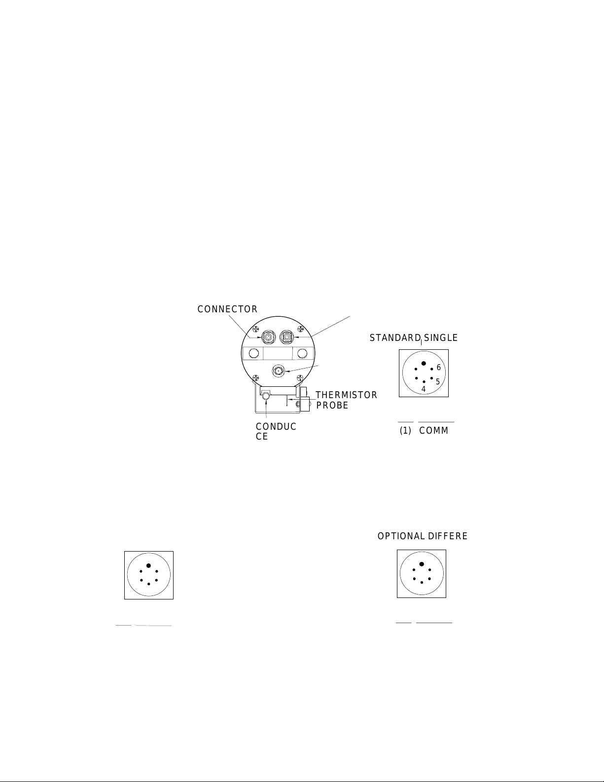
used. In either case, the pump is powered via a Y-cable connected to the 6-pin Data I/O bulkhead
connector on the end cap. Two pins provide power for the pump; the remaining four pins are for
communication and external power (Figure 1) . The Y-cable has 2 branches: one connect ing to the pump,
and the other providing the connection to a computer with a 4- pin male connect or (RMG- 4-MP ) (f igure 2).
If the Profiler is conf igured without a pump, it i s supplied with a 6-pin to 4- pin adapter cable to connect
the Y-cable to the computer.
The SEACAT Profiler can be configured with a wide range of auxiliary sensors. A second 6-pin bulkhead
connector on the end cap serves as the input port for the auxiliary sensor signal voltages and provides
power to the sensors (Figure 1).
Figure 1
Connector Congurations for the SEACAT Profiler.
INPUT/OUTPUT
CONNECTOR
STANDARD I/O CONNECTOR
1
2
4
3
(XSG-4BCL-HP)
PIN
SIGNAL
(1) COMMON
(2) DATA RECEIVE
(3) DATA TRANSMIT
(4) AUX POWER IN
I/O CONNECTOR WITH OPTIONAL PUMP
DATA I/O CONNECTOR
1
6
2
5
3
4
(AG-306-HP)
PIN
SIGNAL
(1) COMMON
(2) DATA RECEIVE
(3) DATA TRANSMIT
(4) PUMP POWER COMMON
(5) PUMP POWER +
(6) AUX POWER IN
AUXILIARY INPUT
THERMISTOR
PROBE
CONDUCTIVITY
CELL
CONNECTOR
STANDARD SINGLE ENDED INPU TS
PRESSURE
PORT
1
6
2
5
3
4
(AG-306-HP)
PIN SIGNAL
(1) COMMON
(2) VOLTAGE 0
(3) VOLTAGE 3
(4) VOLTAGE 1
(5) VOLTAGE 2
(6) AUX POWER OUT
OPTIONAL DIFFERENTIAL INPUTS
1
6
2
5
3
4
(AG-306-HP)
PIN SIGNAL
(1) COMMON
(2) VO LTAGE 0 SIGNAL
(3) VOLTAGE 0 COMMO N
(4) VO LTAGE 1 SIGNAL
(5) VOLTAGE 1 COMMON
(6) AUX POWER OUT
6
Page 11
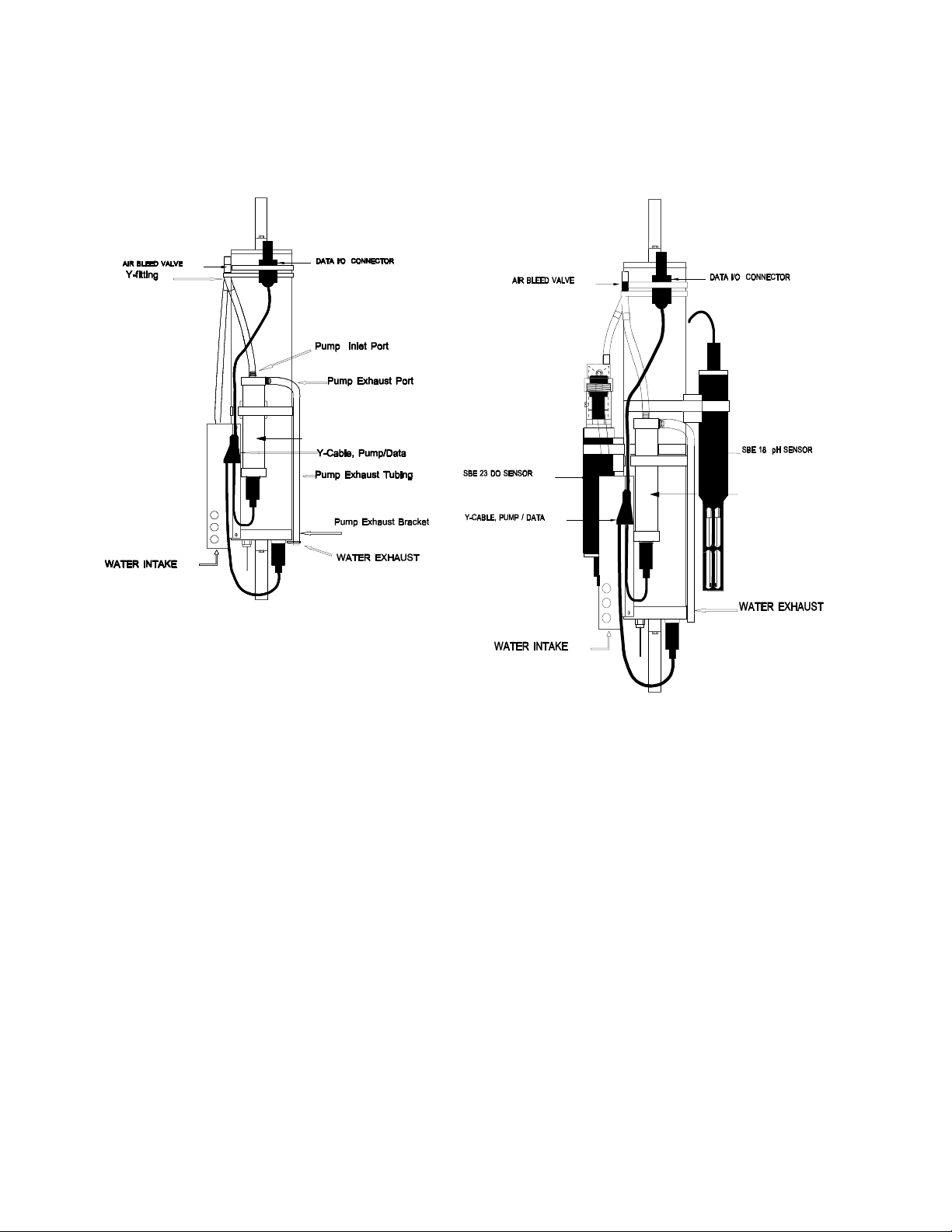
The SEACAT Profiler is configured with the SBE 5 pump t o insure a reliable flow of water through the
p
conductivity cell and optional dissolved oxygen sensor regardless of descent rate. Figure 2 shows the
plumbing arrangement of a CTD equipped w ith a pump. Secti ons 2-2 .6 and 3-1 .2 of t his manual contai ns
additional information on the configuration and operation of the pump.
SBE 5 Pum
SBE 5 Pump
Figure 2
SBE 19 with SBE 5 pump
Figure 3
SBE 19 with pump, and
optional dissolved oxygen and pH sensors
Figure 3 shows the SEACAT Profiler configured with the pump and the optional SBE 23 dissolved ox ygen
and SBE 18 pH sensors. Application note 29 included in this manual contains additional information
concerning the configuration of the SEACAT Profiler with optional sensors.
2-2 SEACAT PROFILER COMMUNICATION FUNDAMENTALS
SEACAT Profiler is factory configured for: 600 baud (1200 baud with optional Paroscientific pressure
sensor), 7 Data Bits, 1 St op Bit, Even Pari ty. SEACAT Prof iler output s - and expects to receive - industry
standard RS-232 levels. If the TERM19 program is used to communicate with the SEACAT Profiler use the
F2 (function 2) key to set these parameters (see Section 2-5).
Remove the rubber cap from SEACAT Profiler' s I/O bulkhead connector or from t he I/O connector on the
pump Y-cable by pulling it firmly upward. Install the Sea-Bird I/O cable connector, aligning t he raised bump
on the side of the connector with the large pin on the SEACAT connector. The other end of the I /O cable
has a DB-25S for connection to your computer's serial port.
7
Page 12

To begin communicating with S EACAT Profiler, the magnetic switch should be of f. Mate the 4-pin test
cable to the computer's serial port. If you are using Sea-Bird SEAS OFT software, the serial port m ust be
an IBM Asynchronous Communications Adapter, or equal. Run the TERM19 program and establish
communications with the Profiler. SEACAT Profiler is now in command mode and may be queried for
various responses as described in the following sections of this manual.
About two minutes of keyboard inactivity will cause SEACAT Profiler t o time out and go into quiescent
state. To regain control, press the ent er or carriage return key (CR ) sev eral ti mes until t he S> is displayed
again. After completing a session with SEACAT Profiler, enter
enter the quiescent state immediately.
If the board-mounted internal lithium bat tery has been removed, disconnect ed, or exhausted, set t he date
and time with the ST command, set the pump parameters with the SP command, and enable the
acquisition of e xte rn al voltages with the SV c o mma n d if a uxiliary sensors are installed.
2-2.1 COMMAND FORMAT
Commands to SEACAT Profiler can be entered in upper or lower case letters. Responses made by SEACAT
Profiler are indicated in b o ld typ e . SE ACAT Pro file r will s en d # whenever an invalid command is entered.
The following table describes the keyboard symbols used in this manual:
qs(CR)
. This will make SEACAT Profiler
Symbol
(CR) Carriage Return CR 0D Return
NULL Null character NULL 00 Home Key
^ Control Key -- -- Ctrl
^C Escape Function ETX 03 Ctrl + C or
^C Escape Function ESC 1B Esc
When running TERM19, the Esc Key must be used to perform the Escape Function.
* Commands followed by * alter SEACAT Profiler memory and will prompt the user twice before
[] Braces indicate optional parameters of the command. Items enclosed in braces need not be entered.
executing (* is not part of the command). To execute the com mand enter Y in response to
Y/N
then hold down the Ctrl key and enter Y i n response to
will abort the comman d .
Description
ASCII
HEX
Key Sequence
are you sure ^Y/N
message
. Any other responses
8
Page 13

2-2.2 EDITING
The following keys are used to edit entries to SEACAT Profiler.
Description
Carriage return: enters the command or line CR 0D
Backspace: deletes the previous character BS 08
Kill line: Ctrl X CAN 18
Kill line: Escape ESC 1B
Kill line: Ctrl C ETX 03
2-2.3 COMMAND SUMMARY
Type
Diagnostics J Measure standby current
Status DS Display current status
Setup CN Set conductivity channel to narrow range (fresh water)
Command
TE Extended memory test
TM Memory test
VR Display voltag e s
FR Display frequencies
CS Set conductivity channel to standard range (salt water)
IR Initialize ram
LW Set time to pause after each line (0 is the default)
MM Set mode to moored
MP Set mode to profiling
PN Disable pump control logic
QS Quit session, enter quiescent state
SB Change default baud rate for communications and real time data
SP Enable and set pump control parameters
SR Set sampling rate (profiling mode)
SI Set sample interval (moored mode)
ST Set date and time
SV Set the number of external voltages to sample
VD Set time to delay before measuring voltages in moored mode
Description
ASCII
HEX
Logging IL Initialize logging
GL Start logging, overwrite existing data
QL Quit logging in moored mode
RL Resume logging, do not overwrite data
HOME KEY or Ctrl-Z will halt logging in profiling mode
Data Retrieval DC Dump data by cast
DD Dump data by scan s
DH Display headers
9
Page 14

2-2.4 DIAGNOSTICS
J(CR)
TE(CR)*^C
pass x
ram 0, OK
ram 1, OK
ram 2, OK
etc.
At the test conclusion or when an Escape Function character is received, SEACAT Profiler displays:
ram test passed with no errors
NOTE
: TE command not available in Profiler firmware version 4.0b or greater.
TM(CR)*^C
VR(CR)^C
Measure Standby current.
Extended memory test.
DESTROYED!
the RAM is then compared to the pattern. Each pass the pattern is incremented by one.
Each pass takes approximately 20 seconds and the test concludes after 10 passes. For
each pass SEACAT Profiler sends the following message:
Memory test.
as extended memory test except that the test concludes after pass 0 is completed.
NOTE
: TM command not available in Profiler firmware version 4.0b or greater.
Display voltages. The first column is the main battery voltage divided by 8.514. The
second column is a voltage that represents the temperature in the pressure sensor The
third column is the pressure sensor voltage. 0, 2 or 4 columns are added after the last
column depending on how many external voltages are sampled.
An incrementing pattern is writ ten into all locations of each RAM. Data in
.
WARNING, ALL DATA IN SEACAT PROFILER WILL BE DESTROYED!
WARNING, ALL DATA IN SEACAT PROFILER WILL BE
Same
CAUTION
Example: VR(CR) SEACAT will send:
0.982 0.745 4.716
FR(CR)^C
CAUTION
: After execution of the VR command, SEACAT will run continuously until the Escape
Function is implemented. Unless an external power source is being used, the normal
170 mA current will be drawn from the battery du rin g th is time.
Display corrected and uncorrected frequencies.
: After execution of the FR command, SEACAT will run continuously until the Escape
Function is implemented. Unless an external power source is being used, the normal
170 mA current will be drawn from the battery du rin g th is time.
10
Page 15

Example: FR(CR) SEACAT will send:
aaaaa.aaa bbbbb.bbb ccccc.ccc ddddd.ddd eeeee.eee fffff.fff
aaaaa.aaa is the 400 ohm reference resistor frequency
bbbbb.bbb is the 5000 ohm reference resistor frequency
ccccc.ccc is the frequency generated by the temperature sensor
ddddd.ddd is the frequency generated by the conductivity cell
eeeee.eee is the corrected temperature frequency
fffff.fff is the corrected conductivity frequency
2-2.5 STATUS
DS(CR)
Example: DS(CR) SEACAT Profiler will send:
SEACAT PROFILER V3.1B SN 936 02/10/94 13:33:06.439
strain gauge pressure sensor: S/N = 12345, range = 1000 psia, tc = 240
clk = 32767.766 iop = 172 vmain = 8.1 vlith = 5.7
mode = PROFILE ncasts = 0
sample rate = 1 scan every 0.5 seconds
samples = 0 free = 174126 lwait = 0 msec
battery cutoff = 7 .2 vo lts
number of voltages sampled = 0
logdata = NO
If the pump is installed and pum p control is enabled via the SP com m and the pump control paramete rs will
be displayed.
Display operating status: software version, serial number and current time;
pressure sensor type, serial number, range and temperat ure compensation value
for strain gauge sensors; real time clock frequency, operating current (milliamps),
main battery voltage, l ithium battery volt age; operating mode, number of stored
casts; sample rate; number of stored samples, number of samples free in
memory, and number of milliseconds to wait after sending a carriage return line
feed (provides extra time for sl ow com put ers); battery cut-of f v ol tage; number of
external voltages that are being sam pled; and whether data is being logged or
not (moored mode)
SEACAT PROFILER V3.1B SN 936 02/10/94 13:33:23.989
strain gauge pressure sensor: S/N = 12345, range = 1000 psia, tc = 240
clk = 32767.766 iop = 172 vmain = 8.1 vlith = 5.8
mode = PROFILE ncasts = 0
sample rate = 1 scan every 0.5 seconds
minimum raw conductivity frequency for pump turn on = 3206 hertz
pump delay = 40 seconds
samples = 0 free = 174126 lwait = 0 msec
battery cutoff = 7 .2 vo lts
number of voltages sampled = 0
logdata = NO
11
Page 16

In moored mode the voltage sample delay is displayed.
SEACAT PROFILER V3.1B SN 936 02/10/94 13:33:39.549
strain gauge pressure sensor: S/N = 12345, range = 1000 psia, tc = 240
clk = 32767.766 iop = 172 vmain = 8.2 vlith = 5.6
mode = MOORED
sample interval = 30 seconds
delay before measuring voltages = 4 seconds
samples = 0 free = 174126 lwait = 0 msec
battery cutoff = 7 .2 vo lts
number of voltages sampled = 0
logdata = NO
If narrow range conductivity has been selected this is displayed in the header.
SEACAT PROFILER V3.1B SN 936 02/10/94 13:33:23.989
strain gauge pressure sensor: S/N = 12345, range = 1000 psia, tc = 240
Narrow Range Conductivity
clk = 32767.766 iop = 172 vmain = 8.1 vlith = 5.8
mode = PROFILE ncasts = 0
sample rate = 1 scan every 0.5 seconds
minimum raw conductivity frequency for pump turn on = 2000 hertz
pump delay = 40 seconds
samples = 0 free = 174126 lwait = 0 msec
battery cutoff = 7 .2 vo lts
number of voltages sampled = 0
logdata = NO
2-2.6 SETUP
SEACAT Profiler functions both as a profiling instrument and a moored or time series instrument. The
differences between these two modes i nvolve how the data are stored and whether the SEACAT runs
continuously or powers off between samples.
In profiling mode
battery supply. The unit sampl es at two samples per second. If t he sample rate is set to a sl ower value,
the unit continues to sample at two samples a second but only stores data at the specified rate. The
longest period between samples is 4 minutes. Temperature and conductivity data are stored as
uncorrected frequencies. The necessary reference frequenci es to convert the dat a to correct ed fr equencies
are stored every 120 samples. See Section 2-3 on data formats for additional information.
Commands that only affect profiling mode are:
PN Disable pump control logic
SP Set pump control parameters
SR Set s a mpling rate
DC Dump data by casts (see Section 2-2.9)
the instrument runs continuously, drawing the full operating current from the main
12
Page 17

In moored mode
seconds. The default amount of time that SEACAT Profiler will provide power to external sensors before
sampling them is 4.0 seconds. This value can be increased to a maximum of 32,000 seconds with the VD
command for instruments such as the Sea T ech fluorometer that need a longer time t o come to a st able
value. In particular, dissolved oxygen sensors require between two and three minutes to polarize after
application of power to the sensor. The voltage delay should be set to a minimum of 120 seconds and the
sample interval to a minimum of 150 seconds if an oxygen sensor is installed. The pump will be powered
for the entire time power is applied to the auxiliary sensors. The increased power going to pump will limit
the number of samples that can be taken to between 350 and 400 when the voltage delay value is set to
120 seconds for an oxygen sensor. The temperature and conductivity data are stored as corrected
frequencies.
Commands that only affect moored mode are:
SI Set sample interval
VD Set time to delay before measuring voltages in moored mode
All SEACAT Profilers are built with the capabilities to record external voltages. If the instrument was
ordered without auxiliary sensors, the number of voltages that the unit acquires was set to zero to
conserve memory usage. The SV command is used to enable this function if an auxiliary sensor is added
at a later date. Corresponding changes to the software conf iguration files also have to be made for the
SEASOFT software to recognize this change
the instrument powers down between sampl es. The f astest sample rate is once every 15
CN(CR)
CS(CR)
IR(CR)*^C
LWN(CR)
MM(CR)
MP(CR)
PN(CR)
QS(CR)
Set conductivity channel to narrow range (fresh water 0 - 0.6 S/m)
If narrow range is set the line 'Narrow Range Conductivity' will displayed in the status.
Set conductivity channel to standard range (salt water 0 - 6.5 S/m)
Initialize RAM (memory):
to 0. Sample number, header number, and data pointers are set to 0. Allow 1.5 minutes to
reset the entire memory. Memory initialization is optional, as SEACAT Profiler will write over
previously recorded information when the gl command (see below) is used. However,
knowledge of the initial memory contents (i. e., all zeros) can be a useful cross check when
data is retrieved .
Set wait interval of N milliseconds after each line of data; normally N = 0; increase for slower
computers. Nmax = 65535.
Set mode to moored.
Set mode to profiling.
Disable pump control logic.
Quit session. Puts SEACAT Prof iler in quiescent mode (50 microamps). Use this command
and then wait 3 seconds before turning on the magnetic switch when in profiling mode.
WARNING, ALL DATA WILL BE DESTRO YED!
All data bits are set
SBn(CR)
Change baud rate used by the SEACAT during normal communications.
13
Page 18

Upon initial power up or reset the SEACAT Profiler will default to communicating at 600 baud. This
command allows the user to change this baud rat e to one of the val ues l ist ed below. W hen this com mand
is given, the SEACAT will immediately change its baud rate and all subsequent communication will be at
the new baud rate. This baud rate will be retained by the SEACAT until power is removed from the circuit
boards (caused by disassembly or by using the reset switch l ocated on the battery bulkhead) or until a
new SB command is entered. The new baud rate is retained while the SEACAT is in quiescent mode
between samples. This setti ng does not affect t he baud rate controlled by the D D and DC commands for
uploading data from the SEACAT.
The possible values are:
n = 1 600 baud
n = 2 1200 baud
n = 3 9600 baud
Example: SB3 set baud rate to 9600
SP(CR)
minimum raw conductivity frequency for pump turn on = xxxx new value =
Enter a new value to change the minimum frequency or press carriage return to accept the current val ue.
The configuration sheet at the begi nning of the manual lists the uncorrected (r aw) frequency out put at 0
conductivity. For most salt water and estuarine applicat ions, enter the 0 conductivity frequency + 500 H z
(factory default) as the minimum frequency. For fresh water, 5 Hertz above the 0 conductivity frequency
is typically used.
pump delay time (seconds) = xxx, new value =
Enter a new value to change the delay tim e or press carri age return to accept the current value. A value of
30 to 45 seconds should give ample time for the tygon tubing and pump to fill with water after the Profiler
has been submerged.
The pump will start after the delay time, and aft er the conduct ivity cell's fr equency output is great er than
the minimum raw conductivity frequency. The pump will stop as soon as the raw conductivity frequency
drops below the minimum.
See Data Format (Section 2-3) for details on computing raw conductivity frequency from HEX data.
SR(CR)
For the pump to prime properly at the surface, it is necessary for the pump and tygon tubing to be
filled with water before the pump is turned on. This command sets the pump turn on parameters.
You will be asked:
Set sample rate as prompted for profiling mode.
Example: SR(CR) SEACAT Profiler will prompt:
number of 0.5 sec intervals between samples =
the sample rate is 1 scan every 0.5 seconds
The maximum allowable number of 0.5 second intervals between samples is 480 (4 minutes between
samples).
1
14
Page 19

SI(CR)
Example: SI(CR) SEACAT Profile r will p ro mp t:
Set sample interval as prompted for moored mode.
number of seconds between samples =
sample interval = 60 seconds
The minimum sample interval is 15 seconds, the maximum is 32000 seconds.
ST(CR)
Example: ST(CR)
date (MMDDYY) =
time (HHMMSS) =
The date is set to April 23, 1987. The time is set to 19:10:26.
SVN(CR)
Example: SV2(CR) will set the nu mb e r of voltages to acqu i re to 2.
The possible values are 0, 2, or 4 voltages.
Enter a new value that reflects the number of external vol tages that are to be recorded through t he 6-pin
auxiliary connector on the end cap. If the number of voltages is changed, a corresponding change must be
made in the software configuration files for the SEASOFT software to recognize the change.
Set date and time as prompted
042387(CR)
191026(CR)
Set the number of external voltages to sample as prompted.
60
VDN(CR)
Example: VD11(CR) will add 11 seconds to the default value of 4.0 seconds.
The default and minimum value is 4.0 seconds. The maximum value is 32000 seconds. N is entered in
seconds. If a Sea Tech Fluorometer is installed, N should be 11 seconds (delay of 15 seconds). If an
oxygen sensor is installed, N should be a minimum of 116 seconds (delay of 120 seconds).
Set the time to delay before measuring external voltages in moored mode.
15
Page 20

2-2.7 LOGGING
In profiling mode, data logging can be initiated by turning on the magnetic switch while the SEACAT
Profiler is in the quiescent st ate or by using the GL or RL commands when the CPU is active and the
magnetic switch is on. Turning on the magnetic switch while the CPU is active will not start logging. If the
switch is left on when the unit is put in the quiescent stat e (ei ther by using t he QS comm and or by t imi ng
out), the unit will start logging when the next attempt to establish communications is made. Logging
commences approximately 5 seconds after t he movement of the switch or the receipt of the GL or RL
command. The first time the switch is turned on after receipt of the IL com mand, the data recording will
start at the beginning of memory and any previously recorded data will be written over, whether the
memory has been initialized or not. When the switch is subsequently turned off, recording will stop. Each
time the switch is turned on again, recording will continue with new data stored after the previously
recorded data and a new header written to indi cate the time, date, increment ed cast num ber, and sam ple
numbers contained in the cast. The maximum number of casts that can be taken is 100.
In moored mode, logging is initiated by using the GL or RL commands. The switch should be l eft in t he off
position, but has no effect on logging. If the switch is turned on while the SEACAT profiler is in the
quiescent state and in moored mode, the CPU will enter the active state but logging will not begin. If no
communications a re e s ta blished the unit will time o u t a n d e n ter the quiescent s ta te a fte r 3 min u te s .
In both profiling and moored mode, data is transmitted real time at 600 baud (1200 baud if the optional
Paroscientific Digiquartz pressure sensor is installed), or at the baud rate specified with the SB command.
If memory is filled to capacity, data logging and the transmission of real time data will continue, but
excess data will no t b e sa ve d in memory.
IL(CR)*
GL(CR)*
QL(CR)
RL(CR)*
Initialize logging. Use this comm and to reset data point ers and the cast number
data has been removed from SEACAT Profiler
Go log. Start logging data. For this command to work in prof iling mode, the magnetic switch
must be on. The first scan is set to 0 so any previously recorded data will be written over,
whether the memory has been initialized or not. This command is useful for l aboratory t esti ng
of SEACAT Profiler when in profiling mode.
Quit logging data in moored mode. When loggi ng data in moored mode, S EACAT Profil er will
respond only to the DS, QS and QL commands. The QL command is given when
communications have been established with SEACAT Profiler and the
Resume logging data. Same as gl command except that the sample number is not reset.
Previously recorded data will not be overwritten. In profiling mode a new cast is started. In
moored mode data is stored after the last previously stored sample.
and prior to recording new data.
S>
prompt is present.
after existing
16
Page 21

2-2.8 STOP LOGGING
In profiling mode, turn off the magnetic switch. Logging may also be terminated in profiling mode by
sending a NULL character (CONTROL Z or HOME KEY in TERM19) to SEACAT Profiler.
In moored mode, logging is terminated by establishing communications with the SEACAT Profiler and
sending the QL command.
2-2.9 DATA RETRIEVAL
In TERM19 data retrieval is determined by the set up of the configuration file. TERM19 communicates
with the SEACAT Profil er using the following commands. T he SEACAT Profiler is capable of t ransmitting
stored data at the following baud rates:
B = 1 600 bau d B = 2 1200 bau d
B = 3 9600 bau d B = 4 19,200 baud
B = 5 38,400 baud
B is the number used below to specify to SEACAT Profiler what baud rate to use to dump data.
DC[Bn](CR)
Example: DC11(CR) SEACAT Profiler will send at 600 baud
Y
aaaaaaaaaaaa
bbbbbbbbbbbb
.
.
nnnnnnnnnnnn
DD[B[n1],n2](CR)^C
Example: DD(CR) SEACAT Profiler will send:
aaaaaaaaaaaa
bbbbbbbbbbbb
.
.
nnnnnnnnnnnn
Display raw data from cast n at the baud rate determined by B. If n i s om i tted, data from cast
0 displayed. If B is omi tted the default baud rat e is used. The first line consists of 'Y ' (valid
cast number) or 'N' (invalid cast number). Subsequent lines have the format described in
section 2-3. This command is valid for profiling mode only.
Valid cast number
scan 0 data, cast # 1
scan 1 data, cast # 1
scan n data, cast # 1, where n+1 is the total number of scans of data stored in cast # 1
Raw data is displayed in HEX at the baud rate specified by B. If B , n1 and n2 are
omitted all logged data is displayed at the default baud rate. Entering n1,n2
displays samples n1 through n2. The data f ormat is described in sect ion 2-3. This
command is valid for both moored and profiling modes.
scan 0 data
scan 1 data
scan n data, where n+1 is the total number of scans of data stored in SEACAT Profiler
17
Page 22

DH[[n1],n2](CR)^C
A new header is written when data logging is started or resumed in profiling mode. In moored mode a new
header is written when data logging is initiated and every 1000 samples thereafter.
Example: DH(CR) SEACAT Profiler will send (moored mo d e )
cast N MM/DD HH:MM:SS samples X to Y sample interval = NNN seconds stop = ZZZ
N cast number
MM/DD HH:MM:SS month, day, hour, minute and second read from real time clock when this cast
X first sample in this c a s t
Y last sample in this cast
NNN is th e s ample interval
ZZZ is the reason logging was halted
Possible values for ZZZ are: batfail battery voltage too low
Display headers. If n1 and n2 are omi tted all headers are displayed. Entering n1
and n2 displays headers n1 through n2. If n1 equals n2 then onl y that one header
is displayed.
was initiated.
switch off magnetic switch turned off
recv cmd received NULL or CNTL Z character, or QL command
timeout error condition
unknown error condition
?????? error condition
In profiling mode the sample rate is shown as the number or scans every NNN seconds.
Sample: DH(CR) (in profiling mode)
cast 0 11/05 08:01:15 samples 0 to 3540 sample rate = 1 scan every 0.5 seconds stop = recv cmd
cast 1 11/05 12:30:33 samples 3541 to 8795 sample rate=1 scan every 0.5 seconds stop=recv cmd
cast 2 11/05 15:45:11 samples 8795 to 10816 sample rate=1 scan every 0.5 seconds stop=switch off
2-3 DATA FORMAT
Data storage format in SEACAT Profiler varies depending on whether the instrument is in moored or
profiling mode.
Data is retrieved from S EACAT Profiler and stored on the computer system i n hexadecimal format using
the program TERM19.
18
Page 23

2-3.1 PROFILING MODE
Temperature and conductivity data are stored as uncorrected (raw) frequencies. The reference data t hat is
used to convert to corrected frequencies is stored in the 5th and 6th scans. Subsequently, after every 120
scans two data scans are replaced by the two reference scans.
2-3.1.1 PAINE STRAIN GAUGE PRE SSURE
Twelve ASCII HEX characters representing six bytes are transmitted per CTD scan. If two external
voltages are sampled, 9 bytes will be transmitted. If four external voltages are sampled, 12 bytes will be
transmitted. A carriage return and line feed follows the data from the last CTD scan.
The data format for CTD scans is:
aaaabbbbpppp
aaaa four HEX characters representing 2 bytes of temperature data
bbbb four HEX characters representing 2 bytes of conductivity data
pppp four HEX characters representing 2 bytes of pressure data
The data format for CTD plus two external voltages is:
aaaabbbbuuuvvvpppp
aaaa four HEX characters representing 2 bytes of temperature data
bbbb four HEX characters representing 2 bytes of conductivity data
uuu three HEX characters representing 12 bits of voltage data (V0)
vvv three HEX characters representing 12 bits of voltage data (V1)
pppp four HEX characters representing 2 bytes of pressure data
The data format for CTD plus four external voltages is:
aaaabbbbuuuvvvxxxyyypppp
aaaa four HEX characters representing 2 bytes of temperature data
bbbb four HEX characters representing 2 bytes of conductivity data
vvv three HEX characters representing 12 bits of voltage data (V0)
www three HEX characters representing 12 bits of voltage data (V1)
xxx three HEX characters representing 12 bits of voltage data (V2)
yyy three HEX characters representing 12 bits of voltage data (V3)
pppp four HEX characters representing 2 bytes of pressure data
Temperature:
1. T = decimal equivalent of aaaa
2. Raw temperature frequency = T / 17 + 1950
Standard Conductivity:
1. C = decimal equivalent of bbbb
2. Raw conductivity frequency = sqrt(C * 2900 + 6250000)
19
Page 24

Narrow Range Conductivity:
1. C = decimal equivalent of bbbb
2. Raw conductivity frequency = sqrt(C * 303 + 6250000)
Voltage:
1. V = decimal equivalent of uuu, vvv, xxx, or yyy
2. Volts = V / 819;
Pressure:
1. P = decimal equivalent of bits 0 through 13 of pppp. Bit 14 is the sign bit. If bit 14 is 0 the
number is positive, if it is 1 the number is negative.
2. Pressure number = P;
If the most significant bit of pppp is a 1, then the CTD scan contains reference resistor frequency
information.
The data for ma t for reference s is:
xxrrrrrrpppp
if xx = 05 then the scan contains high frequency reference data and the conductivity range is Standard
if xx = 08 then the scan contains high frequency reference data and the conductivity range is Narrow
Range
if xx = FF then the scan contains low frequency reference data
pppp is pressure data as described above
rrrrrr is the reference data
If external voltages are recorded they will appear between rrrrrr and pppp as described above.
High frequency reference frequency is the decimal equivalent of rrrrrr / 256.
Low frequency reference frequency is the decimal equivalent of rrrrrr / 256.
The references are read and stored every 120 samples.
Example:
scan 117 = 69CC43220EA4
scan 118 = 052A34398EA5
scan 119 = FF0B45808EA4
scan 120 = 69CE431E0EA5
scan 117 (CTD):
aaaa = 69CC, T = 27084, temperature frequency = 3543.177
bbbb = 4322, C = 17186, conductivity frequency = 7489.286
pppp = 0EA4, P = 3748, pressure number = 3748
scan 118 (High frequency reference)
xx = 05
rrrrrr = 2A3439, Refhi = 10804.225
pppp = 8EA5, P = 3749, pressure number = 3749
20
Page 25

scan 119 (Low frequency reference)
xx = FF
rrrrrr = 0B4580, Reflow = 2885.500
pppp = 8EA4, P = 3748, pressure number = 3748
scan 120 (CTD):
aaaa = 69CE, T = 27086, temperature frequency = 3543.177
bbbb = 431E, C = 17182, conductivity frequency = 7488.511
pppp = 0EA5, P = 3749, pressure number = 3749
The reference data is used to compute the corrected temperature and conductivity frequencies.
The algorithm for computing the corrected frequencies is:
fraw = raw frequency (input to correction algorithm)
fcor = corrected frequency (algorithm output)
fhisq = Refhi * Refh i
flowsq = Reflow * Reflow
fcor = sqrt{ [((fraw * fr aw) - b) / a] - PC }
where:
a = (fhisq - flowsq) / X3
b = flowsq - (a / X2)
using the following constants:
KK = 2.4018669e-11
X1 = 9.6036247e-9
X2 = 1.1949587e-7
X3 = (X2 - X1) / (X2 * X1)
PC = 1 / (1e6 * KK)
Use the corrected values for temperature frequency and conductivity to convert to temperature and
conductivity according to the sensor calibration certificates.
21
Page 26

2-3.1.2 PAROSCIENTIFIC DIGIQUARTZ PRE SSURE SENSOR
18 ASCII HEX characters representing 9 bytes are stored per CTD scan. A carriage return line feed follows
the data from the last CTD scan .
The data format for CTD scans is :
aaaabbbbppppppcccc
aaaa = four HEX characters representing 2 bytes of temperature data
bbbb = four HEX characters representing 2 bytes of conductivity data
pppppp = six HEX characters representing 3 bytes of Digiquartz pressure data
cccc = four HEX characters representing 2 bytes of pressure temperature data
The SEACAT has the capability to record up to four external voltages. If enabled, the voltage data will
appear between the pressure and the pressure temperature data.
The data format for temperature, conduct ivity and external voltages is the same as for t he strain gauge
pressure sensor.
Pressure (Digiquartz):
1. P = decimal equivalent of pppppp
2. Pressure frequency = P / 256.0
Pressure Temperature:
1. C = decimal equivalent of cccc
2. Pressure Temperature Voltage = C / 819.0
3. Pressure Temperature = ( Voltage + 9.7917 ) * 23.6967 - 273.15 (degrees Centigrade)
EXAMPLE
aaaabbbbppppppuuuvvvcccc = 69CC432268D1B8003005908AA
aaaa = 69CC, T = 27084, Temperature Frequency = 3525.474
bbbb = 4322, C = 17186, Conductivity Frequency = 6506.970
pppppp = 8D1B80, P = 9247616, Pressure frequency = 36123.5
uuu = 030, V0 = 48, Voltage 0 = 0.059
vvv = 059, V1 = 89, Voltage 1 = 0.109
cccc = 08AA, C = 2218, Pressure Temperature = 23.0
22
Page 27

2-3.2 MOORED MODE
Moored mode temperature and conductivity data are stored as corrected frequencies. The reference
information is not stored with the data. Ot herwise, the data format i s the same as profiling mode except
for the conversion of temperature and st andard range conductivity from hex adecimal numbers to decim al
frequencies.
The correct scaling for moored mode temperature and standard range conductivity are:
Temperature:
1. T = decimal equivalent of aaaa
2. Temperature frequency = T / 19 + 2100
Standard Conductivity:
1. C = decimal equivalent of bbbb
2. Conductivity frequency = sqrt(C * 2100 + 6250000)
Narrow Range Conductivity:
1. C = decimal equivalent of bbbb
2. Raw conductivity frequency = sqrt(C * 303 + 6250000)
Use these values for temperature frequency and conductivity frequency to convert to temperature and
conductivity according to the sensor calibration certificates.
The conversion of pressure and voltages are the same as profiling mode.
2-4 SEASOFT SOFTWARE CONFIGURATION FILE S
The program TERM19 is used to communicate with and retrieve data from SEACAT Profiler. TERM19
creates the file TERM19.CFG to store its setup parameters so they do not have to be reentered every
time. The file TERM1 9.CF G, w ith t ypical set- up paramet ers for using y our SEACAT (assum ing instal lat ion
on C: drive) is included on the SEASOFT distribution disks that accompanied your SBE 19.
The program SEACON creates or modifies a f ile SEASOFT.CON, which is used by SEASOF T modules to
obtain calibration coefficients and instrument configuration information. For new instruments this
information was entered at t he factory, and a correct copy of this file should have been included on t he
software distribution disks that accompanied your SBE 19. If the instrument is recalibrated or the
configuration is changed (such as adding external sensors), SEACON must be run to either enter t he new
calibration information or to modify the instrument configuration settings.
Refer to the instrument "configuration page" and/or calibration certificates in this manual, and the
SEASOFT software manual for additional information.
23
Page 28

2-5 OPERATION USING TERM19
TERM19 is a terminal emulation program designed to communicate with SEACAT Profiler: characters
typed on the keyboard are sent to SEACAT Prof iler and characters sent by SEACAT Profiler are displayed
on the console. TERM19 expects to find the file TERM19.CFG in the current directory.
SEACAT Profiler will automatically send ^S and ^Q characters if the comput er does not keep up with the
data sent by SEACAT Profiler.
The main terminal scre en is shown below:
┌──────────────────────────────────────────────────────────────────────────────┐
│
SBE 19 Terminal Program 4.0 Thursday January 16, 1992 4:50 pm
├──────────────────────────────────────────────────────────────────────────────┤
│
<F1> Help <F2> Setup <F3> Status <F4> Headers <F5> Capture
│
<F6> Wake Up <F7> Baud Rate <F8> Init Log <F9> Upload <F10> Exit
│
│
│
│
<F1>Help <Ctrl-C>Halt Instr <Ctrl-F10 or Home>Stop Log Baud = 600 Capt = NO
└──────────────────────────────────────────────────────────────────────────────┘
│
│
│
│
│
│
│
Press F2 and select Communication Set Up to set the COMM port and baud rate. Exit the Set Up form
(press Esc) and press F6 to establish communications with the instrument. To abort the attempt to
establish communications press the Esc Key.
Once communications have been established characters transmitted by the instrument will be displayed in
the center portion of the main screen.
The active function keys are:
F1
F2
F3
F4
F5
F6
Display help screens.
Display the termina l s e t u p form.
Display instrument status.
Display instrument headers.
Capture instrument responses to a file on disk (use F9 for data upload).
Reestablish communications with the instrument. The instrument will 'go to sleep'
after two minutes without receiving any commands from the computer.
F7
F8
Change the baud rate.
Initialize logging. Reset the scan and cast pointers in t he instrument to 0. U pload any
data in the instrument before sending this command.
24
Page 29

F9
Upload data from the instrum ent. The upload parameters are configured i n the set up
menu (Function Key 2).
F10
Exit to DOS.
Ctrl-C Sends Ctrl-C to the instrument to halt the display voltages and display frequencies
diagnostics.
Ctrl-F10 or Home Stop Logging (sends a Null character to the instrument).
On the bottom status line:
Baud =Displays the current baud rate
Capt =Displays the capture to disk status. If Y ES all replies from the inst rum ent are being written to a file
on disk.
The function keys are used to control various features of the term inal program and to send commands to
the instrument for data uploading, initializat ion, and status information. If communi cations or instrument
problems are encountered, refer to Section 2-2 for the diagnostic and data commands.
In particular, if the terminal program is not able to establish communications with the instrument by
cycling through the baud rates and comm ports , set the baud rate (as documented on the conf iguration
page) with the F7 key and verify the set up parameters accessed through the F2 key. Subsequent
attempts at communicating with the instrument can be made by pressing the enter key or via the F6 key.
2-5.1 TERMINAL SET UP FORM
┌──────────────────────────────────────────────────────────────────────────────┐
│
SBE 19 Terminal Program 4.0 Thursday January 16, 1992 4:50 pm
└──────────────────────────────────────────────────────────────────────────────┘
╔══════════════════════════════════════════════════════════════════════════════╗
║
TERM19 Set Up Parameters
╠══════════════════════════════════════════════════════════════════════════════╣
║
SBE 19 EPROM (Firmware) Version = 3.0 or Greater
║
║
Communication Set Up = <Press Enter To Modify>
║
║
Data Upload Set Up Parameters = <Press Enter To Modify>
║
║
Header = Prompt for Header Information
║
║
Header Form = <Press Enter To Modify>
║
╚══════════════════════════════════════════════════════════════════════════════╝
<F1> Help; <Esc> Exit; <Enter> Modify the field
│
║
║
║
║
║
║
║
║
║
║
║
The EPROM Version is recorded on the conf iguration sheet of your instrum ent manual and also displayed
in the first line of th e r e p ly to the display statu s (F3) r e p l y.
25
Page 30

The Communication Set Up Form is:
┌──────────────────────────────────────────────────────────────────────────────┐
│
SBE 19 Terminal Program 4.0 Thursday January 16, 1992 4:51 pm
└──────────────────────────────────────────────────────────────────────────────┘
╔══════════════════════════════════════════════════════════════════════════════╗
║
TERM19 Set Up Parameters
╠══════════════════════════════════════════════════════════════════════════════╣
║
SBE 19 EPROM (Firmware) Version = 3.0 or Greater
║
║
Communi║ Communication Set Up = ║
║
║
Data Up║ Serial Port = COM1 ║
║
║ ║
║
Header ║ Baud Rate = 300 ║
║
║ ║
║
Header ║ Data Upload Baud Rate = 9600 ║
║
║ ║
║
║ Data Bits = 8 Data Bits ║
║
║ ║
║
║ Parity = No Parity ║
║
║ ║
║
║
║
╚══════════════════════════════════════════════════════════════════════════════╝
<F1> Help; <Esc> Exit; <Enter> Modify the field
╔════════════════════════════════════════════════════════════╗
╠════════════════════════════════════════════════════════════╣
╚════════════════════════════════════════════════════════════╝
│
║
║
║
║
║
║
║
║
║
║
║
║
║
║
║
║
║
║
Standard instruments are set to 7 data bits, even parity
Firmware Versions Less than 3.0:
baud rate = 9600
upload baud rate = 9600
Firmware Versions 3.0 or greater:
baud rate = 600
upload baud rate is programmable to 600, 1200, 9600, 19200, or 38400
use slower upload baud rates with slow computers and long cables.
use 38400 baud with short cables and 386- or 486-based PCs.
26
Page 31

2-5.2 DATA UPLOAD SETUP FORM
┌──────────────────────────────────────────────────────────────────────────────┐
│
SBE 19 Terminal Program 4.0 Thursday January 16, 1992 4:51 pm
└──────────────────────────────────────────────────────────────────────────────┘
╔══════════════════════════════════════════════════════════════════════════════╗
║
TERM19 Set Up Parameters
╠══════════════════════════════════════════════════════════════════════════════╣
║ ╔══════════════════════════════════════════════════════════════════════════╗ ║
║ ║
Data Upload Set Up Parameters = ║
║ ╠══════════════════════════════════════════════════════════════════════════╣ ║
║ ║
Upload = Upload One Cast ║
║ ║
║
║ ║
Echo During Upload = Display One '.' Every 16th...║
║ ║
║
║ ║
Output HEX Data File Path = C:\CTDDATA\ ║
║ ║
║
║ ║
Upload File Name Choice = Prompt for File Name ║
║ ║
║
║ ║
Default Upload File Name [.HEX] = upld ║
║ ║
║
║ ║
Upload Session Number [0-99] = 3 ║
║ ║
║
║ ╚══════════════════════════════════════════════════════════════════════════╝ ║
╚══════════════════════════════════════════════════════════════════════════════╝
│
║
║
║
║
║
║
║
║
║
║
║
║
║
║
The Upload choices are:
Upload All Data Separated by Casts:
All data will be uploaded. A separate file will be written for each cast.
Upload Data By Cas t Nu mber Range:
The user will be prompted for the beginning and ending cast numbers. A separate file will be
written for each cast.
Upload One Cast:
The user will be pro m p te d fo r th e c a s t n umber range. One file will b e written.
Upload All Data as On e File :
The terminal program will send the 'DD' (dump data) command rather than the 'DC' dump cast
command to the instrument. For diagnostic use only with SBE 19. One file will be written.
Upload Data By Scan Number Range:
The terminal program will prompt the user for the beginning and ending scan number and then
send the 'DD' (dump data) command to the instrument. For diagnostic use only. One file will be
written.
27
Page 32

The Echo Choices are:
Echo Data During Upload:
The HEX data from the instrument is displayed on the screen as it is received
Display One '.' Every 16th s c a n during Upload :
Will shorten the time required to uplo a d th e data.
Output HEX Data File Path =
Enter the path where you wish the uploaded HEX file to be written.
Upload File Name Cho ic e :
If one cast is uploaded at a time the upload file name can be up to 8 characters long. TERM 19 will add
a .HEX extension to the name.
If multiple casts are uploaded ( 'Upload All Data Separat ed by Casts' is selected in the set up form ) then
the filename can be up to 6 characters long. Term 19 will add 2 characters signifying the cast number
to the name and add a .HEX extension to the name.
If the upload file name choice is 'Use Default File Name' then the uploaded file name is:
NNNNXXYY.HEX where
NNNN is the default u pload file name (one to four ch a r a c te r s )
XX is the upload session number
YY is the cast number
Header:
Include Default Header in Upload File:
The default header form is included in the upload file. The user is not prompted to add any
information.
Prompt For Header Information:
Each time a cas t is uploaded the u s e r will b e prompted to fill out th e header form
Don't Include Header in Upload File:
Header information is not included in the upload file
Upload File Name Cho ic e =
Use Default File Name:
The user is not prompted for the file name. The upload session num ber and cast number are added
to the default file name to form the actual file name.
Prompt for File Name:
The user is prompted for the file name.
28
Page 33

Default Upload File Na me [.HEX] =
If the upload file name choi ce is 'Use Def ault Fil e Name' then this def ault f ile name is used al ong with
the upload session number and the cast number to f orm the com plete upl oad fi le. The m axim um lengt h
for the default file name is 4 characters. The file name extension need not be entered.
Upload Session Number [0 - 99] =
The upload session number is incremented each time data is uploaded (Functi on Key 9). It is reset by
setting this field to 0.
Header Form:
The header form is customized by editing t his f orm. The ent ries are f ree form and 0 t o 12 lines may be
entered. If header = 'Prompt for Header Information' this form will be displayed for the user to fill in. If
header = 'Inclu d e Default Header', on ly this form will be included in the uploa d file .
2-5.3 TERMINAL PROGRAM: FIELD OPERATION
Connect the instrument to the computer's serial port. Run TERM19 ( the file TERM19.CFG creat ed during
setup should be in the current directory). Press F6 to establish communications with the SBE 19
(...communications established... will be displayed when this occurs and the S> will show on the screen
indicating that the SBE 19 is ready t o accept com mands) . I f comm unicat ions are not est abli shed, press F 2
and select Communication Set U p. Verify that the seri al port, baud rate, data bits, and parity are correct
for your configuration.
To upload data, press Function Key F9. The prompts that you see will be determined by the current setup
read from TERM19.CFG. TERM19 will automa tic a lly o b ta in s ta tus a n d header information fro m th e SBE 19
and then proceed to transfer the data to the upload file(s ). When the upload is complete, the screen will
display the message 'Data U pload is Complet e, Press < ESC> t o continue'. Press <ESC> to continue. If
you wish to reset the memory point ers to initialize logging press Funct ion Key 8. In addition to resett ing
the pointers TERM19 will p u t th e SBE 19 in quiescent mo d e a n d then return to DOS.
2-6 DATA RECORDING AND REA DOUT: SA MPL E SESSIONS
These examples assume the software has been installed on the computer. Consult the S EASOFT manual
for installation instruction s .
Connect SEACAT Profiler to the serial port with the cable supplied.
There should be new (or freshly charged) batteries in SEACAT Profiler.
29
Page 34

2-6.1 SAMPLE SESSION - PROFILING MODE
Verify that the file SEASOFT.CON is correct for your system by running the SEACON program and
examining the instrument configuration and calibration information with that contained in this manual.
2-6.1.1 RECORD DATA WITH SEACAT PROFILER (COMPUTER INITIATED)
1. If the magnetic switch is on , tu r n it off.
2. Connect SEACAT Profiler test cable to SEACAT Profiler and the RS-232C port on an IBM PC/XT/AT or
compatible. Type cd \profiler to change to the profiler subdirectory. Type term19.
3. Enter DS(CR) to display SEACAT Profiler status. A typical response would be:
SEACAT PROFILER V3.1B SN 936 02/10/94 13:33:06.439
strain gauge pressure sensor: S/N = 12345, range = 1000 psia, tc = 240
clk = 32767.766 iop = 172 vmain = 8.1 vlith = 5.7
mode = PROFILE ncasts = 0
sample rate = 1 scan every 0.5 seconds
samples = 0 free = 174126 lwait = 0 msec
battery cutoff = 7 .2 vo lts
number of voltages sampled = 0
logdata = NO
4. Turn the magnetic switch on. Enter GL( CR) [go log comm and].
recorded data has not yet been removed from SEACAT
start logging Y/N ?
the GL command automatically initializes SEACAT Profiler; it is not necessary to send the IL command
before sending the GL command.)
5. After a few seconds you will see data (in HEX) displayed on the CR T at 2 scans per second. Wait a
few minutes while 'cast 0' data is recorded by SEACAT Profiler.
6. Press the HOME key to end 'cast 0'. S> will be displayed.
7. To record a second cast repeat steps 4 - 6, entering RL(CR) [resume logging] instead of gl(CR) in
step 4.
2-6.1.2 RECORD DATA WITH SEACAT PROFILER (MAGNETIC SWITCH INITIATED)
1. If the magnetic switch is tur n e d on, turn it off.
2. Connect SEACAT Profiler test cable to SEACAT Profiler and the RS-232C port on an IBM PC/XT/AT or
compatible. Type cd \profiler to change to the profiler subdirectory. Type term19.
. Type ^y(CR) [ CTRL Y] in response to t he prompt
Profiler. Type y(CR) in response to the prom pt
Do not use this command if previously
are you sure ^Y/N ?
. (Note that
30
Page 35

3. Enter DS(CR) to display SEACAT Profiler status. A typical response would be:
SEACAT PROFILER V3.1B SN 936 02/10/94 13:33:06.439
strain gauge pressure sensor: S/N = 12345, range = 1000 psia, tc = 240
clk = 32767.766 iop = 172 vmain = 8.1 vlith = 5.7
mode = PROFILE ncasts = 1
sample rate = 1 scan every 0.5 seconds
samples = 505 free = 173616 lwait = 0 msec
battery cutoff = 7 .2 vo lts
number of voltages sampled = 0
logdata = NO
4. Enter IL(CR) to 'init ialize logging'. Type y (CR) in response to the prompt
^y(CR) [CTRL Y] in response to the prompt
recorded data has not yet been removed from SEACAT Profiler
5. Enter DS(CR) to display SEACAT Profiler STATUS. Check that ncasts = 0 and samples = 0.
6. Enter QS(CR) to 'quit session' and put SEACAT Profiler in quiescent mode.
7. Wait 3 seconds, then turn on the magnetic switch to begin l ogging data. Aft er a few seconds you wil l
see data (in HEX) displayed on the CRT at 2 scans per second. Wai t a few m inutes whil e 'cast 0 ' data
is recorded by SEACAT Profiler.
8. Turn off the magnetic switch and wait a few seconds. This will terminate the recording of 'cast 0'.
Turn on the magnetic switch again t o resume data logging. Turn off the magnetic sw itch after a f ew
minutes to end recording of 'cast 1'.
2-6.1.3 RETRIEVE DATA FROM SEACAT PROFILER
Before attempting to retrieve data, it will be necessary t o record data in SEACAT Prof iler by following the
steps outlined in section 2-6.1.2 above. To retrieve the recorded data:
1. If the magnetic switch is tur n e d on, turn it off.
are you sure ^Y/N ?. Do not use this command if previ ously
.
initialize logging Y /N ?
. Type
2. Connect the SEACAT Profiler test cable to SEACAT Profiler and the RS-232C port on an IBM PC/XT/AT
or compatible. Type cd \profiler to change to the profiler subdirectory. Type term19.
3. Enter DS(CR) to display SEACAT Profiler status. The following is typical:
SEACAT PROFILER V3.1B SN 936 02/10/94 13:33:06.439
strain gauge pressure sensor: S/N = 12345, range = 1000 psia, tc = 240
clk = 32767.766 iop = 172 vmain = 8.1 vlith = 5.7
mode = PROFILE ncasts = 2
sample rate = 1 scan every 0.5 seconds
samples = 1505 free = 172616 lwait = 0 msec
battery cutoff = 7 .2 vo lts
number of voltages sampled = 0
logdata = NO
31
Page 36

4. Enter DH(CR) to display headers.
cast 0 09/10 08:01:15 samples 0 to 924 sample rate = 1 scan every 0.5 seconds stop = recv cmd
cast 1 09/10 12:30:33 samples 925 to 1504 sample rate = 1 scan every 0.5 seconds stop = recv
5. Use the F2 key to verify the data upload parameters are set correctly.
6. Use the F9 key to upload the data into a hexadecimal file.
In each file (one per cast) will be stored the DS and DH command responses as well as the hexadecimal
data itself. Each line of the DS or DH responses will be will have an asterisk in the first position.
7. Press F10 to r eturn to DOS.
2-6.1.4 DISPLAY SEACAT PROFILER DATA USING SEASOFT
The program SEASAVE is used to display the 'raw' hexadecimal data output from SEACAT Profiler in
engineering units, and compute derived variables. In the main screen of SEASAV E, select archi ved data to
view recorded files, or select real-time data to log directly to a computer disk. In the next SEASAVE
screen, the type of display and other param eters are set before the data are actually present ed. Refer to
the SEASOFT manual for det ailed information on the use of the SEASAVE program, as well as the other
programs used to analyze, process, and plot SBE 19 data.
3-1 INSTALLATION AND OPERATING INSTRUCTIONS
SEACAT Profilers are shipped with new alkaline batteries installed, unless rechargeable nickel cadmium
batteries were ordered.
for the first time
the SEACAT Profiler will be in quiescent mode drawing 50 microamperes or less. The initialization routines
described below will have been performed at the factory and the real-time clock will be running (set t o
Pacific Time).
To gain experience with SEACAT Profiler communications prot ocol, the S ample Set -up Sessions descri bed
in Section 2-6 may be follo we d at this time.
If a separate power supply is available and will be used for testing, connect the power supply to the 4 pin
bulkhead connector (see Section 2-1 for hook-up instructions).
Power will be drawn from either the main batteries, the external power source, or the internal printed
circuit-mounted lithium back-up cells (5.6 volts), depending on which voltage source is highest.
having the magnetic switch turned on when neither main battery nor external power sources are
connected.
If using a Sea-Bird junction box, connect the box to SEACAT Profiler using the 4-pin to MS cable provided.
Connect the box to the computer serial port using the DB-25 cable. Connect AC m ains power. Press the
red power button to provide power to SEACAT Profiler. The junction box supplies about
15 volts, so SEACAT Profiler's batte rie s will n ot be depleted whe n th e ju n c tio n box is in use.
(see Application note 21 in t his manual for chargi ng and use inst ructions). As delivered,
Rechargeable batteries should always be charged before using the SEACAT Profiler
Avoid
32
Page 37

3-1.1 BATTERY INSTALLATION
Unthread the battery compartment end cap (end cap without any connectors). Remove the t hree Phillipshead machine screws from the battery retainer plate immediately inside the pressure housing. Lift this
plate clear. Batteries are instal led with the + term inal against the flat battery cont acts and the - terminal
against the spring contacts. Sl ide the batteries into their respecti ve slots. Align the retainer plate so that
the flat and spring contacts are over the + and - battery contacts respectively, and re-install the plate.
screws must be fully tightened, or battery power to the circuitry will be intermittent
voltage (approximately 9 volts) at the screw heads marked BAT POS and BAT NEG. If the magnetic
switch is turned off, the Profiler will enter quiescent mode. In this mode, the clock runs and memory is
kept alive, but the power drain i s only about 50 microam peres. Check t he ' O' - ring and m ati ng surf ace and
rethread the end cap.
3-1.2 PUMP OPERATION
Normally, the conductivity cell must be in water before the pump will run. After the cell enters the water,
there is a delay before turn-on so that all the air in the pump t ubing can escape. If the pump m otor turns
on when there is air in the impeller housing, primi ng i s uncertain and a proper flow rate cannot be ensured.
The tubing extending above the air-bleed hole will contain a small reserve of water. This maintains the
pump prime (for up to one minute, depending on the length of tubing above the air-bleed), even though the
Profiler is lifted up so t hat the cell inlet and pump outlet are just below the w ater surface. This allows
beginning the actual profile very near the top of the water.
above the water surface or the prime will be lost.
5 seconds, then turn the switch on, submerge the SEACAT complet ely, and wai t for t he pump delay ti me
before beginning the profile.
If this happens, turn the switch off. Wait at least
The cell inlet and pump outlet must not come
. Check for battery
The
Pump turn-on occurs when two conditions programmed using the SP (set pump) command have been met:
'raw frequency' from the conductivity interface circuit exceeds the minimum 0 conductivity frequency
value entered, and the delay interval has elapsed.
For oceanic water in the 35 ppt range, enter the set point for the minimum 0 conductivity frequency as
3500 Hz, since actual in-water frequencies will always be higher. For fresh/nearly fresh water, the set
point frequency must be only slightly higher (e.g., 5 Hz) than the 0 conductivity 'raw frequency' shown on
the instrument configuration sheet . If the set point is too cl ose to the 0 conductiv ity 'raw frequency,' the
pump may turn on when the SEACAT is in air as result of small drifts in the electronics. Some
experimentation may be required, and in some cases it may be necessary to rely only on the pump delay
time to control the pump. If so, set a frequency lower than the '0 conductivity raw frequency' value.
The second entry made via the SP command sets the time delay. The necessary delay can be j udged by
immersing the Profiler (switch off, not running) just below the air-bleed hole at the top of the tygon tubing.
Measure the time needed to completely fill the tubing (30 seconds is typical) and set the delay to about
1.5 times longer. When actually using the Profiler, be sure to 'soak' t he instrument just under t he surface
for at least the time required for pump turn on.
Entries made with the SP comm and are permanently stored in the Profiler and remain i n effect until you
change them. The only exception is if the Profiler is completely reset. This occurs only with disassembly of
the electronics from the housing (along with disconnection of t he battery connector to the electronics card
set) or if the toggle swi tch at the bottom of t he battery compart ment (newer unit s only) is placed in the
'reset' position.
33
Page 38

3-1.3 DEPLOYMENT
Check that the anodes have not been eroded away, and that hardware and ext ernal fittings are secure.
Refer to Section 2 for information on program ming SEACAT Profi ler for the desired operati ng routine, and
confirm that memory capacity is suffici ent. Make sure that the self-diagnostic battery voltage is proper.
A screen dump (to a printer) of SEACAT P rofiler' s response to the DS command makes a usef ul record of
the instrument's pre-deployment condition.
In general, the following steps should be taken before putting the Profiler in the water:
1. Turn the magnetic switch off (slide towards connector end cap).
2. Use the IL command to initialize the memory.
3. Use DS to check that time, date, vbatt are satisfactory and that ncasts = 0 and samples = 0.
4. Use QS to return SEACAT Profiler to qui escent conditions.
switch is turned on before auto power-down (about 2 minutes later)
Put a light coating of silicon grease
5.
connector I/O port.
6. Remove the Tygon tubing (usually filled with deionized water) looped end-to-end around the
conductivity cell.
7. Immediately prior to deployment, turn on the magnetic switch (slide towards the center of the case).
The Profiler is ready to go into the wate r .
on the dummy cover and install it on SEACAT Profiler' s bulkhead
If this step is omitted
Profiler will not take data!
, and the magnetic
3-1.4 OPTIMIZING DATA QUALITY
Experience has shown that a profiling speed of about 1 meter/second is usual l y satisfactory. However, the
magnitude of ship motion, and the dynamic ef fect it has on data quality , has to be considered as operating
conditions change. Slow profiling speeds (especially with an unpumped CTD) causes degraded fl ushing of
the conductivity cell, and ‘ sal i ni ty spiking’ can be severe in areas of strong t em perature gradients. In rough
seas or other conditions (small boats) where the ship’s dynamic motion is large, the profiling speed should
be increased (up to as much as 2-3 meters/second) to reduce the dynamic errors (‘spiking’ ) caused by t he
rapidly changing rate of descent/ascent of the CTD (yo-yo effect).
In common with other CTD equipment, the Profiler is intended for obtaining downcast data, and will not
generally give best quality resul ts on the upcast. If you must have upcast data, invert the Profiler so that
the sensors are at the top - in which case t he downcast data should be ignored.
the instrument not be positioned in a way that causes the water that will flow past its sensors to be
thermally contaminated by other instruments, sample bottles, etc
temperature and conductivity of the water in which they are immersed, and it i s quite remarkable how
much this can be influenced by other objects! SEACATs equipped with the submersible pump are abl e to
get better data with slow descent rates than unpumped SEACATs. Since t he pump creates and maint ains
a constant and optimum flow, the SEACAT can be l owered more slowly to give great er vert ical resol ution
in the profile data, especially on lakes, protected bays, or other calm conditions. The minimum descent
rate for pumped SEACATs should be adjusted according to t he magnitude of shi p motion (i. e., sea stat e).
On a very calm lake, 10 cm/second is feasible if used with a constant winch speed.
. The sensors will respond to the
It is very important that
When a pumped SEACAT is installed on a water sampler, good conductivity (and optional dissolved
oxygen) data can be collected, even when stopped to collect a water sample, because the water will
continue to flow through the sensors. However, the manner in which the SEACAT is mounted on the
34
Page 39

water sampler can have a dramatic effect on data qualit y. The opt ional SEACAT T-C D uct can be used to
overcome dynamic errors induced by a poor mounting method or location (see Application Note 51).
Where the water temperature is markedly different from the temperature at which the Profiler has been
stored, better results will be obtained if the Profiler is allowed to equilibrate to the water temperature at
the surface (soak) for a minute or two before begi nning the profile. The reason is not that the electroni cs
are temperature sensitive - t hey are not - but that t he thermal influence of the instrument housing on the
water entering the cell will be reduced. In cases where the difference between water temperature and
SEACAT storage temperature are extreme, more 'soak time' should be allowed.
'Spiking' is sometim es seen in t he derived val ues for sal init y, density , or sound v elocit y and resul ts largel y
from response time mismatching of the conductivity and temperature sensors, especially when the
profiling descent rate is non-uniform. This is a problem in all CTD work, and the suppressi on of the effect
(it is never eliminated) has been the goal of instrument manufacturers and ocean researchers for many
years. The greatest immunity to spiking will be found in premium CTD equipment such as the Sea-Bird
SBE 9, which uses very fast sensors (0.07 second), high speed (24 Hz) parallel signal acquisition, and a
pumped-flow (constant tim e response) conductiv ity sensor. SEACAT Prof iler's st atic accuracy i s the same
as that achieved by the SBE 9, but its dynamic responses - owi ng to its simpler, less costly, and more
compact design - are not as ideal.
The amount of 'spiking' with SEACAT Profiler will depend on the temperature gradient encountered, and
will be much worse where coupled surface motion causes the instrument to stop - or even reverse - its
descent. In the event of heavy ship motion, it may be worth letting the instrument 'free-fall'.
Where very heavy seas cause severe ship motion and result in periodic reversals of the instrument
descent, it is possible to greatly improve the data set by removing those scans t aken when the pressure
signal is not increasing. Consult t he SEASOFT manual for information on programs that can be used to
correct data for the influences of ship motion and to minimize salinity spiking.
3-1.5 RECOVERY
CAUTION!! IMPROPERLY SEALED PRES SURE HOUSINGS MAY FLOOD IN SUCH A WAY AS TO TRAP
AND COMPRESS THE AIR INSIDE. IF THIS HAPPENS, A POTENTIALLY LIFE-THREATENING EXPLOSION
CAN OCCUR WHEN THE INSTRUMENT IS BROUGHT TO THE SURFACE.
ACCORDINGLY, A MALFUNCTIONING INSTRUMENT SHOULD BE TREATED WITH GREAT CAUTION
UNTIL IT HAS BEEN DETERMINED THAT ABNORMAL INTERNAL PRESSURE DOES NOT EXIST, OR HAS
BEEN RELIEVED.
IF THE SEACAT IS UNRESPONSIVE TO I/O COMMANDS OR SHOWS OTHER SIGNS OF FLOODING OR
DAMAGE, LOOSEN EACH OF THE SENSOR END RETAINING HARDWARE 1/2 TURN. IF THERE IS
INTERNAL PRESSURE, THE END CAP WILL `FOLLOW' THE SCREWS OUT, AND THE SCREWS WILL
NOT BECOME EASIER TO TURN. IN THIS EVENT, LOOSEN THE I/O BULKHEAD CONNECTOR AT LEAST
TWO TURNS TO RELIEVE ANY INT E RNAL PRESSURE.
Rinse the conductivity sensor with fresh water, and replace the distilled-water filled Tygon tubing.
Remove the dummy cover from t he I/O port, and connect S EACAT to a com puter serial port . If the main
batteries are exhausted, they must be replaced before data can be read out.
35
Page 40

The program TERM19 (supplied with SEACAT) may be used with an IBM PC/XT/AT or compatible to
create MS-DOS fil es from the recorded data.
put on a write-protect tab, and store the disk in a safe place
Leave the main batteries in place when storing SEACAT to prevent depletion of the back-up lithium cells
by the real-time clock. Even an 'exhausted' main battery will power the clock (50 microamperes) almost
indefinitely. Sea-Bird's SEASOFT CTD data acquisition software may be used to tabulate and plot the
archived data set. See the SEASOFT Installation Instructions for further information.
3-1.6 STORAGE
SEACAT Profiler should be rinsed with fresh water after use and prior t o storage. When possibl e, keep t he
conductivity cell in distilled water (see section 5-1.2 CONDUCTIVITY CELL STORAGE). If SEACAT Profiler
is to be stored for long periods, the batteries should be left in place and changed yearly.
4-1 COMMON PROBLEMS AND THEIR CURES
The most common difficulties w ith SEACAT Profiler involve im proper setup of the SEASOFT routi nes in
the companion computer. Read the software manual for general guidance.
Profilers are shipped with the software set up to match the configuration of your instrument, and have the
calibration coefficients already entered. We recommend that you make copies of the SEASOFT disks
supplied, place write-protect stickers on the originals, and store them in a secure place. Then do your
actual work using the copies.
Make a back-up disk containing a copy of the MS- DOS f ile,
!
4-1.1 UNABLE TO COMMUNICATE WITH PROFILER
The I/O cable supplied with Profiler will permit connection to the DB- 25P input connectors used on 'IBM
Asynchronous Adapter Cards', i.e., standard RS-232 interfaces. Pin 1 of the Profiler I/O bulkhead (large
pin) goes to DB-25 pin 7 (ground). Pr ofiler pin 2 (CCW f rom large pin) goes to DB- 25 pin 2, and Profil er 3
(opposite the large pin) goes to DB-25 pin 3.
If you are using an IBM PC or equival ent and cannot establish communication (the S> is not displayed in
response to multiple [CR]s), verify the setup parameters in TERM19. TERM19 permits choice of
communications port 1 or 2 (must agree with your serial card configuration) and of the I/O baud rate
which must be 600 baud, even parity, one stop bit for standard Profilers (1200 baud for Profilers with a
Paroscientific Digiquartz pressure sensor). TERM19 writes a file called 'TERM19.CFG' to the current
directory.
communications may be established.
This file must be copied to the directory from which TERM19 is being run before
36
Page 41

4-1.2 NO DATA RECORDED
Profiler must be in quiescent mode before it will respond to the magnetic swit ch and begin taking data.
Quiescent mode is entered by entering QS[CR] when communicating with a computer or terminal, or
waiting about 3 minutes after the last keyboard command. It is best to always use the QS command when
ending a data readout, diagnostic, or set-up session with a computer or terminal.
Verify that the memory is not full (use the DS command; 'f ree = 0' if memory i s full). O nce the memory
is full, no further data will be recorded. It is generally best to upload all previous data before beginning
another deployment. Then use the IL command to reset memory. DS will show 'samples = 0' and 'free =
42958' (or 'free = some other number', depending on the Profiler’s memory capacity).
4-1.3 NONSENSE DATA
If an uploaded data file yields nonsense values (9999.99, for example), the problem is usually an incorrect
value in the instrument configuration or firmware version as entered in SEACON.
CONFIGURATION at the beginning of the manual for the correct configuration of your CTD system
If the TERM19 program fails to correctly upload the data, verify that the firmware version (see
configuration page) and the data upload baud rate in the TERM19 setup (F2 key) are set correctly.
Unreasonable values for temperature, conductivity, etc. are usually the result of incorrect entries i n the
calibration coefficients section of SEACON. Check that the values entered agree with the calibration
certificates supplied with your unit.
See INSTRUMENT
.
4-1.4 RESETTING THE SBE 19's INTERNAL MEMORY
In rare cases the memory resident program that controls the microprocessor in the SBE 19 can be
corrupted by a severe static shock or other problem. This program can be reloaded from the EPROM
located in the SBE 19 by removing all power from the internal circuitry. When the main batteries are
removed or exhausted, the small lithium batteries located on the i nternal circuit cards keep memory al ive.
If the lithium battery power is removed from the circuitry, the SBE 19 will lose all memory. When power is
reapplied, a fresh copy of the firmware is loaded into volatile memory from the EPROM.
On the battery side of t he bulkhead located in the SBE 19 housing is a small two- position switch. This
switch can be used to disconnect the internal lithi um batteri es from t he electronics. Access to t his swi tch
is through the battery compartment . When the main batteries are removed, this sw itch is visible on the
battery bulkhead. To reset the SBE 19, move the switch to the reset position and leave it there for
5 minutes to allow several capacitors to drain. Then m ov e t he sw i tch back to the on position. Reinstall the
main batteries and communicate with the SBE 19 using the TERM19 program.
NOTE: All contents of memory will be lost when the SBE 19 is reset. This includes data stored in memory
and all variable parameters that are user configurable.
Use the ST command to reset the date and ti me, the SV command to enable the acquiring of external
voltages, and the SP command to reset the pump start parameters.
37
Page 42

5-1 ROUTINE MAINTENANCE AND CALIBRATION
5-1.1 CORROSION PRECAUTIONS
On aluminum-housed units, t here is a large zi nc anode screwed into t he battery end- cap, and a second on
the conductivity cell guard is also used on plastic versions. These anodes should be checked f rom time t o
time to see that they are securely fastened, and have not been eaten away.
All the stainless steel screws t hat are exposed to salt w ater have been generously l ubricated wit h NEVER
SEEZ Blue Moly (available through marine hardware stores). After a deployment, it is wise to remove these
screws and re-lubricate them with a similar com pound. This compound is electrically conduct ive, so care
should be used not to get it on circuit boards.
SEACAT Profiler should be rinsed with fresh water after use and prior to storage.
5-1.2 CONDUCTIVITY CELL STORAGE
When possible, keep the conductivity cell in distilled water during periods of non-use by looping a length of
water-filled Tygon tubing end to end. If it is not practical to leave the conductivity cell stored with distilled
water in it (due to the danger of freezing, for example) merely rinse the cell with distilled water after each
use (to remove salt water), then blow lightly through the cell to insure that no water is trapped inside. This
is easily done using the Tygon tubes supplied. Loop the tubing end to end of the cell to keep out airborne
contaminants. If the cell has been stored dry, wet with a 1% solution of Triton X 100 (or other non-ionic
detergent) before use. Triton X100 may be obtained through a medical supply distributor.
5-1.3 SENSOR CALIBRATION
Sea-Bird sensors are calibrated by subjecting them to known physical conditions, and measuring the sensor
responses. Then coefficients are computed which may be used with appropriate algorithms to obtain
engineering units. The conductivity and temperature sensors on SEACAT Profiler are supplied fully
calibrated, with coefficients as printed on their respective Calibration Certificates.
SEACAT Profiler may be returned to Sea-Bird for calibration or calibrated using standard laboratory
equipment and methods. If the latter is elected, Sea-Bird can supply software for coefficient generation.
Because temperature is varied to yield a wide range of conductivities from baths of just two salinities,
performance of a conductivity calibration on SEACAT Profiler will always yield a temperature calibration as
well.
If SEACAT Profiler is recalibrat ed, run SEACON and enter the new cali bration coefficients
the menu prompts.
in response to
38
Page 43

5-1.3.1 CONDUCTIVITY SENSOR CALIBRATION
The conductivity sensor incorporates a fixed preci sion resist or in parall el wi th t he cell. When t he cell i s dry
and in air, the sensor's electrical circuitry will output a frequency representative of the fixed resistor. This
frequency is recorded on the calibration certificate and should remain stable (within 1 Hz) over time.
The primary mechanism for calibration drif t i n conducti vit y sensors is t he f ouling of the cel l by chem ical or
biological deposits. The effect is to change the cell geom etry, resulting in a shift in cell constant. A second
drift mechanism is associated w i th change in the quality of the pl atinized electrodes, and this effect is al so
induced by fouling. Accordingly, the most im portant determi nant of long- term sensor accuracy i s t he stat e
of cleanliness of the cell, and it is for this reason that storage in distilled water is suggested.
We recommend that the conductiv ity sensors be calibrated before and after im portant deployments, but
particularly when the cell has been exposed to contamination by oil slicks or biological material.
5-1.3.2 TEMPERATURE SE NSOR CALIBRATION
The primary source of temperature sensor calibration drift is the aging w i th time of the thermist or el em ent .
This will usually be a few thousands of a degree during the first year, and less in subsequent intervals. The
sensor drift is not substanti al l y dependent upon the environmental conditions of use, and -- unli ke platinum
or copper elements -- the thermistor sensor is insensitive to shock.
5-1.3.3 PRESSURE SENSOR CALIBRATION
The strain-gauge pressure sensor is a semi-conductor type, which is capable of meet ing S EACAT Prof iler' s
error specification with some all owance for aging and ambient-temperature induced drift . For demanding
applications, or where the sensor's air ambient pressure response has changed significantly, calibration
using a dead-weight generator is recommended. The end-cap's 5/ 16-24 straight thread permits mechanical
connection to the pressure source. The pressure port uses an oil-filled capillary to buffer the pressure
sensor against rapid thermal variations (a source of short-term error) and to prevent galvani c reactions in
aluminum housed units.
To recalibrate the pressure transducer, remove the ny lon fitting (with short at tached 1/8-inch OD plastic
tube) from the lower end cap of the sensor housing. There is silicon oil in this fitting, so there will be some
spillage. The end cap is tapped with a 5/16-24 straight thread t o accept your pressure fitting. U se a fitting
that has an O-ring face seal, such as Swagelok-200-1-OR.
After calibration, turn the instrument so the lower end cap is facing up, remove the fitting and fill the
cavity with silicon oil (such as Dow Corning DC200 fluid, with 200 centistokes viscosity). Use a 2-inch
long 21 gauge hypodermic needle (supplied, with syringe) inserted as far as it will go into the small hole at
the bottom of the cavity. Then replace the nylon fitting. The oil in the cavit y should fill the nylon fitting
and 1/8-inch tube as the fitting is screwed in.
39
Page 44

6-1 DESCRIPTION OF SEACAT PROFILER CIRCUITRY
SEACAT Profiler circuitry is contained on three rectangular (approximately 75 X 250 mm) printed boards
supporting analog, cpu, and memory funct ions. The cpu and m emory boards are interconnect ed at several
points by means of pin and socket SIP connectors to form a digital 'module'. A single DIP interboard
connector is used to carry the 26 lines between the analog board and the digital module.
6-1.1 BATTERY WIRING AND POWE R SUPPL Y
SEACAT Profiler's main batt ery is a series connection of 'D '-cells that drop i nto the battery com partment
as a cluster of three end-to-end st acks (t hree batt eries each) . The posit iv e batt ery connecti ons are contact
areas on double-thick printed circuit disks that form the internal bulkhead and battery retainer plates.
Battery negative contacts are heavy beryllium-copper springs. The three cell stacks are aligned by plastic
insulated aluminum spacers which also serve as electrical interconnects. The battery-to-circuit card
connection is made by means of a Molex-type 6-pin pc board connector (J6).
The Analog board contains two series-connected lithium cells (1/2 AA non-hazardous) which are diode
OR'd with the main battery (and external power source, if used). The lithium supply is capable of
supporting all SEACAT Profiler f unctions and serves to permit orderly shut-down in the event of failed or
exhausted main batteries.
Whenever the main power switch is 'on', battery voltage is connected to a low-power regulator chip
(Intersil 7663) used to supply 5 volts (+ 5C) to the real-time clock (RTC) and memory circuits. When a
conductivity/temperat ure sample is to be taken, the RTC 'wakes up' the CPU by switching on a power
MOSFET to connect battery voltage to the main supply regulator (National Semiconductor LM 2950, +
5volts). The CPU checks that main battery voltage is adequate (minimum 5.9 volts) before proceeding
with the measurement routine.
6-1.2 SENSOR MULTIPLEXING
The conductivity cell and thermistor are sequentially connected to a single Wein-bridge oscillator circuit by
means of mercury-wetted relays dri ven by NPN saturated switches under cont rol of the CPU. The relays
will retain their low (0.1 ohm) initial contact resistance within 0.005 ohms throughout a life-time of
200 X 10
6
operations minimum (over 3 years continuous operation of S EACAT Profiler). Every 120th scan
substitutes two reference resistors to allow arithmetic cancellation of most of the electronic drift sources.
Relay coil power is derived directly from the unregulated battery line through emitter-follower Q7. The
advantage is that the system regulator is not requi red to handle the ( relativ ely large) and intermit tent rel ay
coil current.
40
Page 45

6-1.3 WEIN-BRIDGE OSCILLATOR
The Wein-bridge oscillator (WBO) is configured as a controlled-gain amplifier using high-frequency bipolar
transistors and low-valued load resistors to achieve minimum phase shift. An input FET provides high
impedance to the WBO frequency -determi ning components ( two fi xed capacitors, a fixed resistor, and t he
unknown sensor resistance) while an emitter follower presents and a low driving impedance to the
MOSFET gain control element.
The WBO output of 0. 16 volts p-p (smal l enough to avoid signifi cant self-heati ng in the SEACAT Profiler
sensors) is amplified to supply the higher AC level (approximately 1. 2 volts p-p) needed to activate the
AGC detector.
6-1.4 SQUARING CIRCUITS AND AP COUNTE R
The amplified WBO output is squared by CMOS inverters connected as Schmidt-triggers. While the
squared WBO signal is selected by t he CPU controlled MUX, the AP counter circuit (on the Memory board)
is used to count its frequency. A 12-bit CMOS counter (4040) acquires the integer count during a 0.125
second interval, while a second 4040 counts the TCXO frequency (2.097 mHz) to yield a number
representing the 'fractional' cycle of the input frequency. The CPU uses the two counts to compute a
single number representative of WBO frequency, at a resolution equal to 1/(0.125 X 2.097e6) or
1/262,000. This is comparable to the counter resolution obtained with other Sea-Bird CTD equipment.
6-1.5 A/D CONVERTER (INTERNAL DIAG NOSTIC S)
A 12-bit plus sign A/D converter (National S emiconductor ADC1205) is used on the CPU board to obt ain
diagnostic information relating to SEACAT Profiler status and functionality. A pre-amplifier and buffer
(Precision Monolithics OP220) are used to condition the internal signal levels selected by the MUX. Main
supply current is determined by measuring t he voltage across a 0. 5 ohm resist or, while m ain unregulated
and lithium back-up voltages are sensed using resistive dividers. To assure ability of the back-up lithium
supply to power SEACAT Profiler f unctions, its voltage is measured under typical l oad. SEACAT Profiler
quiescent current (RTC and memory only supported) is also measured by the A/D.
6-1.6 CPU AND DATA I/O
SEACAT Profiler's CPU is configured around an 80C85 CMOS 8-bit microprocessor (CPU board), with
program storage in CMOS EPROM (27C256, Memory Board). Communication with SEACAT Profiler is via
RS-232 interface to the XR88C681 UAR T (CPU Board), while level conversion is handled by a LT1081;
this chip serves a double role in supplying a source of +/- 12 v power used to drive the A/D converter' s
precision 5 volt reference (PMI REF02).
A time-out signal is generated which resets the CPU after 5 seconds of cpu inactivity. The time-out
feature is intended to protect agai nst inadvertent incapacitat ion resulting f rom some unforeseen sof tware
'loop'. The reset inhibit is detected on the CPU Board in response to periodically imbedded lines of code
which cause a write instruction to location C1 HEX.
41
Page 46

6-1.7 REAL-TIME CLOCK
RTC oscillator circuitry (Memory Board transistor oscillator, CMOS buffer/squaring) is on the Memory
Board. A flip-flop converts the 3 v p-p squared oscillator output to the 5 volt level required for SEACAT
Profiler's digital circuitry. The RTC oscillator frequency is count ed during each data acquisition cycle using
SEACAT Profiler's precision TCXO. The results are used to ari thmetically correct the int er-sample interval
and recorded time. The clock/calendar chip is on the CPU Board (National Semiconductor MM58167A).
CPU Board uses tri-state buff ers to protect t he clock/calendar from inadvert ent wake- alarm rewrit e during
power-up.
6-1.8 MEMORY
Eight low-power CMOS static RAM chips (Memory Board, Hitachi HM628128) are used for main data
memory. Bank switching is used, and memory contents protected on power-up by tri-state latches.
7-1 DISASSEMBLY/REASSEMBLY INSTRUC TIONS
COMPLETE DISASSEMBLY WIL L DESTROY ANY DATA PREVIOUSLY STORED IN SEA C A T PROFIL ER!
Great care must be taken during assembly and reassembly to avoi d breaking t he conductiv it y cell . The cell
is robust and well protected when the i nstrument is intact, but becomes extremely vulnerable during the
disassembly/reassembly procedure.
Remove the four machine screws retaining the sensor guard to the housing and set the guard aside.
Remove the small screw holding t he upper (opposite end- cap) end of the conducti vity cell to the housing.
Now remove the four screws retaining the sensor end-cap to the cylindrical housing. The end-cap and
attached electronics chassis may now be sli d out of the pressure cylinder. The Molex connector toward
the battery end of the analog electronics board (the board to which the yellow lithium batteries are
mounted) must be unmated before the chassis/end-cap assembly may be fully removed.
For reassembly, reverse the disassembly process, being careful t hat the mat ing surfaces are clean and the
'O'-ring greased, undamaged, and properly positioned. Use a new desi ccant package. Re- mate the Molex
connector (be careful that the connector socket holes are lined up properly with respect to the mating
header pins).
42
Page 47

7-2 O-RING SIZES
O-RING SIZES (600, 3400, AND 6800 METER CASE PROFILERS)
Battery end-cap (piston) seal: Parker 2-234E603-70
Battery end-cap (face) seal: Parker 2-153N674-70
Sensor end-cap (piston) seal: Parker 2-233E603-70
Sensor end-cap (crush) seal Parker 5-374E603-70
I/O bulkhead connector: Parker 2-017N674-70
Conductivity cell penetrator: Parker LS-001
O-RING SIZES (7000 AND 10500 METER CASE PROFILERS)
Battery end-cap (piston) seal: Parker 2-234E603-70
Battery end-cap (face) seal: Parker 2-153N674-70
Sensor end-cap (piston) seal: Parker 2-233E603-70
Sensor end-cap (crush) seal Parker 5-374E603-70
I/O bulkhead connector: Parker 2-017N674-70
Conductivity cell face seal: Parker 2-110E603-70
43
 Loading...