

Page 1
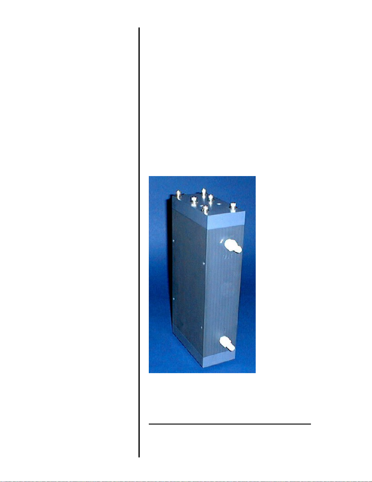
SBE 45 MicroTSG
THERMOSALINOGRAPH
Conductivity and Temperature Monitor
with RS-232 Interface
Serial Number: 4566782-0402
User Manual, Version 015
Sea-Bird Electronics, Inc.
13431 NE 20th Street
Bellevue, Washington 98005 USA
: 425/643-9866
Tel
Fax:425/643-9954
Page 2

This page intentionally left blank.
Page 3

SBE 45 MICRO-TSG OPERATING AND REPAIR MANUAL
Manual Generation Date....................................................................................................................................................................................................................................
1
Limited Liability Statement...............................................................................................................................................................................................................................
2
Declaration of Conformity.................................................................................................................................................................................................................................
4
SBE 45 Configuration - S/N 0402...........................................................................................................................................................................................................................
5
SBE 45 Manual - Version 015...............................................................................................................................................................................................................................
6
SBE 45 Reference Sheet - Version 007......................................................................................................................................................................................................................
59
SBE 45 Specification Sheet................................................................................................................................................................................................................................
61
PN 90402 Manual - Version 008.............................................................................................................................................................................................................................
63
SBE 45 Calibrations.......................................................................................................................................................................................................................................
95
Appnotes..................................................................................................................................................................................................................................................
98
Drawings..................................................................................................................................................................................................................................................
125
Warranty..................................................................................................................................................................................................................................................
136
Service Request Form......................................................................................................................................................................................................................................
139
TABLE OF CONTENTS
SEA-BIRD ELECTRONICS, INC.
13431 NE 20th St.
Bellevue, Washington 98005 USA
Phone: (425) 643 9866
Fax: (425) 643 9954
Email: [email protected]
Page 4

1
Manual Generation Date: 13 February 2012
Page 5

2
L I M I T E D L I A B I L I T Y S T A T E M E N T
Extreme care should be exercised when using or servicing this equipment. It should be used or
serviced only by personnel with knowledge of and training in the use and maintenance of
oceanographic electronic equipment.
SEA-BIRD ELECTRONICS, INC. disclaims all product liability risks arising from the use or servicing of
this system. SEA-BIRD ELECTRONICS, INC. has no way of controlling the use of this equipment or of
choosing the personnel to operate it, and therefore cannot take steps to comply with laws pertaining to
product liability, including laws which impose a duty to warn the user of any dangers involved in
operating this equipment. Therefore, acceptance of this system by the customer shall be conclusively
deemed to include a covenant by the customer to defend, indemnify, and hold SEA-BIRD
ELECTRONICS, INC. harmless from all product liability claims arising from the use of servicing of this
system.
Page 6

3
This page intentionally left blank.
Page 7
4
Page 8

Instrument Configuration:
Serial Number 37SI64195-8524
Pressure Sensor None
Firmware Version 3.0j
Memory 8192Kb
Interface Type RS-232
Conductivity Range 0-7 S/m
Baud Rate 9600, 8 data bits, no parity
Zero Conductivity 2491.031 Hz
Maximum Depth 7000 meters
5
SBE45 MicroTSG
(Thermosalinograph)
Conductivity & Temperature Monitor
with RS-232 Serial Interface
Instrument Configuration:
Serial Number 4566782-0402
Firmware Version V 1.1b
Interface Type RS-232
Conductivity Range 0-7 S/m
Baud Rate 4800
Power Up Jumper Autopower Pins 1 & 2
Maximum Depth 0
CAUTION - This instrument is not intended for
underwater use.
Page 9
6
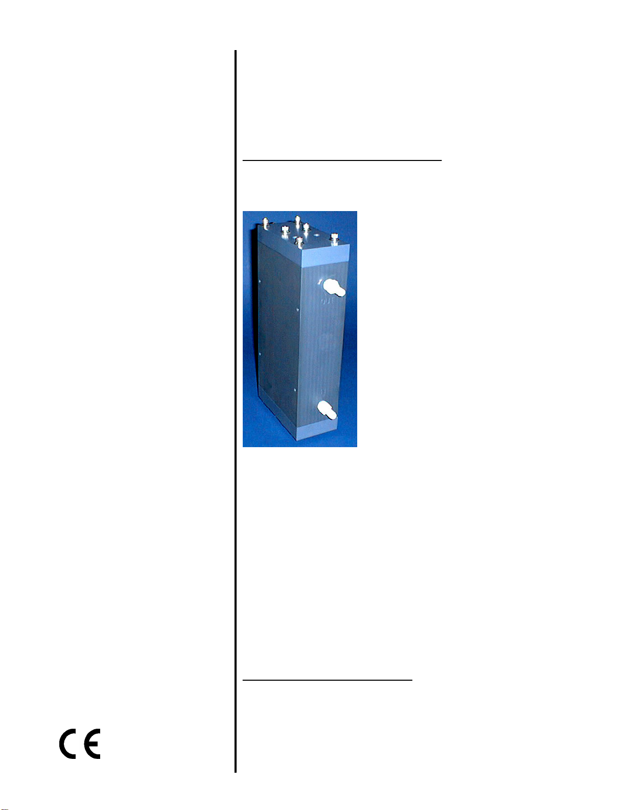
SBE 45 MicroTSG (Thermosalinograph)
Conductivity and Temperature Monitor
with RS-232 Interface
Note: NEW ADDRESS
as of January 18, 2010
User’s Manual
Sea-Bird Electronics, Inc.
13431 NE 20
Bellevue, Washington 98005 USA
Telephone: 425/643-9866 Manual Version #015, 01/26/10
Fax: 425/643-9954 Firmware Version 1.1b and later
E-mail: [email protected] Seasave V7 Version 7.20a and later
Website: www.seabird.com SBE Data Processing Version 7.20a and later
th
Street
Page 10

7
Limited Liability Statement
Extreme care should be exercised when using or servicing this equipment. It should be used or serviced
only by personnel with knowledge of and training in the use and maintenance of oceanographic
electronic equipment.
SEA-BIRD ELECTRONICS, INC. disclaims all product liability risks arising from the use or servicing
of this system. SEA-BIRD ELECTRONICS, INC. has no way of controlling the use of this equipment
or of choosing the personnel to operate it, and therefore cannot take steps to comply with laws
pertaining to product liability, including laws which impose a duty to warn the user of any dangers
involved in operating this equipment. Therefore, acceptance of this system by the customer shall be
conclusively deemed to include a covenant by the customer to defend, indemnify, and hold SEA-BIRD
ELECTRONICS, INC. harmless from all product liability claims arising from the use or servicing of
this system.
2
Page 11

8
Table of Contents SBE 45
Table of Contents
Section 1: Introduction ........................................................................ 5
About this Manual .............................................................................................5
Quick Start.........................................................................................................5
Unpacking MicroTSG........................................................................................6
Section 2: Description of MicroTSG .................................................. 7
System Description............................................................................................7
Specifications.....................................................................................................9
Dimensions and Connector..............................................................................10
Sample Timing.................................................................................................11
Baud Rate, Cable Length, Power, and Data Transmission Rate......................12
Remote Temperature Sensor (optional)...........................................................14
Section 3: Installing System .............................................................. 15
Installing Software...........................................................................................15
System Schematic and Installation Guidelines ................................................16
Power-Up Jumper Check .................................................................................18
Installing MicroTSG ........................................................................................19
Section 4: Setting Up MicroTSG ...................................................... 20
Communications Test and Setup......................................................................20
Sampling Modes ..............................................................................................24
Polled Sampling........................................................................................24
Autonomous Sampling .............................................................................25
Serial Line Synchronization (Serial Line Sync)........................................26
Timeout Description ........................................................................................26
Command Descriptions....................................................................................27
Data Output Format .........................................................................................32
Setting Up Configuration (.xmlcon or .con) File .............................................33
Section 5: Operating System ............................................................. 34
Acquiring Real-Time Data with Seasave.........................................................34
Processing Data................................................................................................36
Section 6: Routine Maintenance and Calibration.......................... 37
Corrosion Precautions......................................................................................37
Cleaning and Storage.......................................................................................37
Replacing Anti-Foulant Device (SBE 45)........................................................39
Sensor Calibration............................................................................................40
Section 7: Troubleshooting................................................................ 41
Problem 1: Unable to Communicate with MicroTSG......................................41
Problem 2: Nonsense or Unreasonable Data....................................................41
Problem 3: Salinity Lower than Expected .......................................................41
Glossary .............................................................................................. 42
3
Page 12

Table of Contents SBE 45
Appendix I: Functional Description................................................. 43
Sensors.............................................................................................................43
Sensor Interface ...............................................................................................43
Appendix II: Electronics Disassembly/Reassembly ........................ 44
Appendix III: Command Summary ................................................. 45
Appendix IV: AF24173 Anti-Foulant Device .................................. 47
Appendix V: Replacement Parts ...................................................... 51
Index.................................................................................................... 52
9
4
Page 13

10
Section 1: Introduction SBE 45
Section 1: Introduction
This section includes a Quick Start procedure, and photos of a standard
SBE 45 MicroTSG shipment.
About this Manual
This manual is to be used with the SBE 45 MicroTSG Conductivity and
Temperature Monitor. It is organized to guide the user from installation
through operation and data collection. We’ve included detailed specifications,
command descriptions, maintenance and calibration information, and helpful
notes throughout the manual.
Sea-Bird welcomes suggestions for new features and enhancements of our
products and/or documentation. Please contact us with any comments or
suggestions ([email protected] or 425-643-9866). Our business hours are
Monday through Friday, 0800 to 1700 Pacific Standard Time (1600 to 0100
Universal Time) in winter and 0800 to 1700 Pacific Daylight Time (1500 to
0000 Universal Time) the rest of the year.
Quick Start
Follow these steps to get a Quick Start using the MicroTSG.
The manual provides step-by-step details for performing each task:
1. Perform pre-check procedures (see Sections 3 and 4):
A. On the Configuration Sheet (in the manual), check the factory-set
power-up mode jumper setting. For a description of how the jumper
setting affects operation, see Power-Up Jumper Check in Section 3:
Installing System.
B. Test power and communications.
C. Establish setup and operating parameters.
D. Check status (DS) and calibration coefficients (DC) to verify setup.
2. Deploy the MicroTSG (see Sections 3, 4, and 5):
A. Verify the AF24173 Anti-Foulant Device is installed.
B. Install the MicroTSG.
C. Send commands to run the system.
5
Page 14
Section 1: Introduction SBE 45
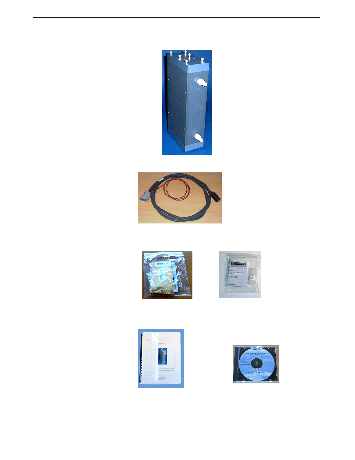
Unpacking MicroTSG
Shown below is a typical MicroTSG shipment.
I/O cable
Spare parts kit
MicroTSG User Manual
MicroTSG
Conductivity cell cleaning
solution (Triton X-100)
Software, and Electronic Copies of
Software Manuals and User Manual
11
6
Page 15
12
Section 2: Description of MicroTSG SBE 45
Section 2: Description of MicroTSG
This section describes the functions and features of the MicroTSG, including:
• System description
• Specifications
• Dimensions and connector
• Sample timing
• Baud rate, cable length, and power requirements
• Optional remote temperature sensor
System Description
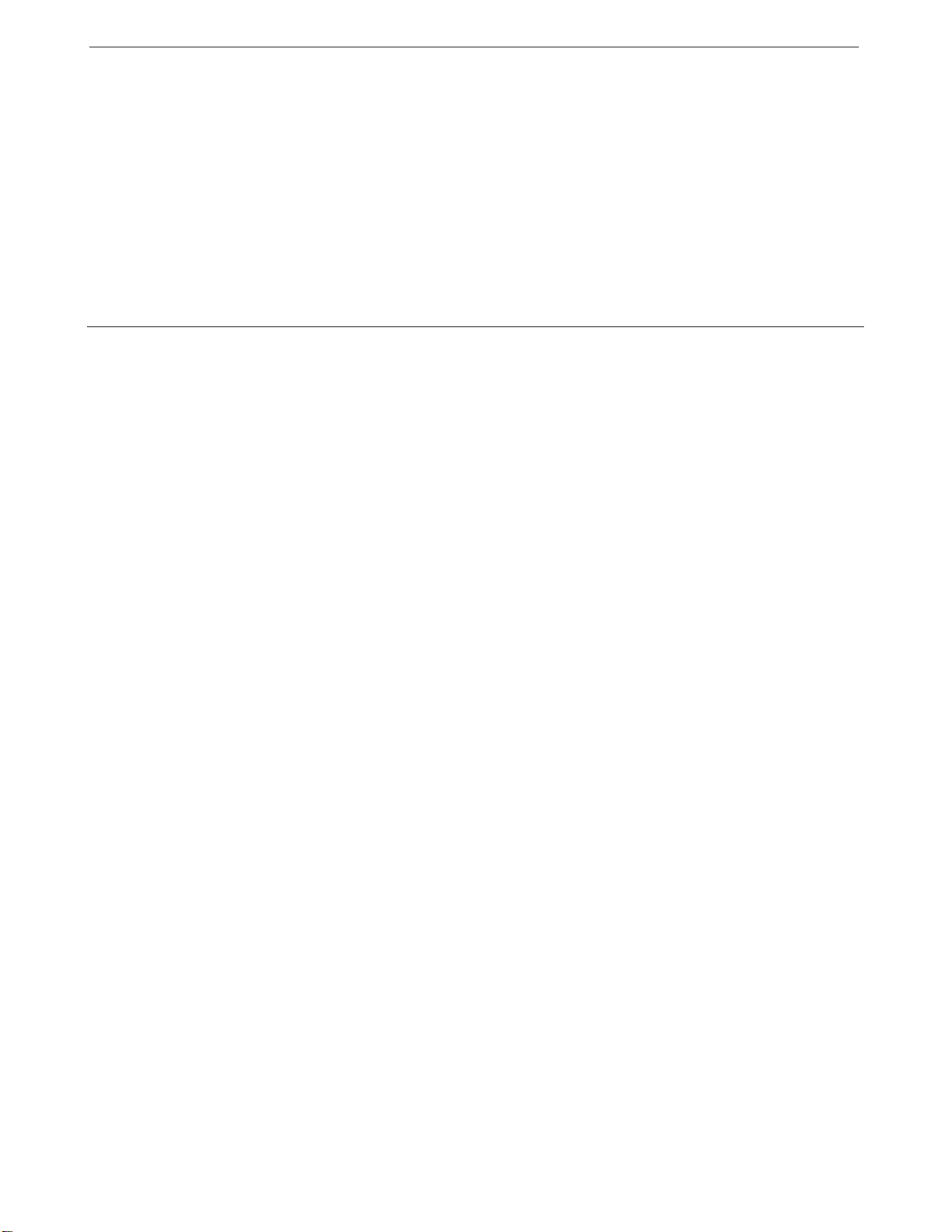
The SBE 45 MicroTSG is an externally powered, high-accuracy, conductivity
and temperature monitor, designed for shipboard determination of sea surface
(pumped-water) conductivity and temperature.
Communication with the MicroTSG is over an internal, 3-wire, RS-232C link,
providing real-time data transmission. Commands can be sent to the
MicroTSG to provide status display, data acquisition setup, data acquisition
and display, and diagnostic tests. User-selectable operating modes include:
• Polled sampling – On command, the MicroTSG takes one sample and
sends the data to the computer.
• Autonomous sampling – At pre-programmed intervals, the MicroTSG
samples and sends the data to the computer. The MicroTSG does not enter
quiescent (sleep) state between samples.
• Serial Line Sync - A pulse on the serial line causes the MicroTSG to
wake up, sample, and enter quiescent (sleep) state automatically.
Calibration coefficients stored in EEPROM allow the MicroTSG to transmit
data in engineering units. The MicroTSG retains the temperature and
conductivity sensors used in the SBE 21 Thermosalinograph, but has improved
acquisition electronics that increase accuracy and resolution, and lower power
consumption. The MicroTSG’s aged and pressure-protected thermistor has a
long history of exceptional accuracy and stability (typical drift is less than
0.002 °C per year). Electrical isolation of the conductivity electronics
eliminates any possibility of ground-loop noise.
The MicroTSG’s internal-field conductivity cell is unaffected by external
fouling. A plastic cup with O-ring retainer at one end of the cell retains the
expendable AF24173 Anti-Foulant Device.
7
Page 16
Section 2: Description of MicroTSG SBE 45
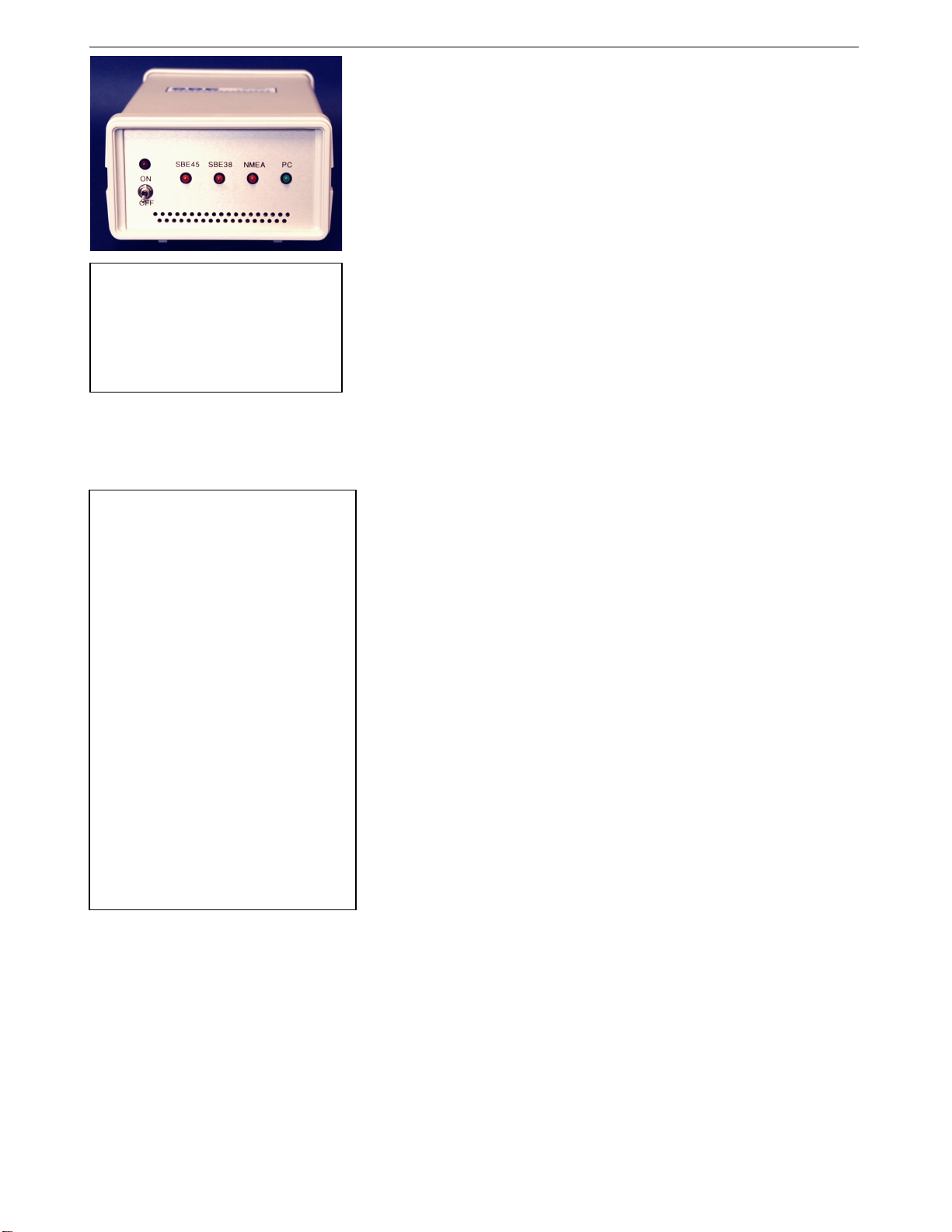
An optional AC- or DC-powered 90402 - SBE 45 Power, Navigation, and
Remote Temperature Interface Box provides:
• Power and an opto-isolated RS-232C interface for the MicroTSG
• An opto-isolated NMEA receiver for an optional NMEA navigation
device which supports NMEA 0183 protocol, outputting data in GGA,
GLL, RMA, RMC, or TRF format (NMEA navigation device not supplied
by Sea-Bird)
• Power and an RS-232C interface for an optional SBE 38 remote
Note:
See the Interface Box manual for
operation of the MicroTSG with the
Interface Box. The Interface Box can
be added to the system at any time,
and does not need to be part of the
original MicroTSG order.
temperature sensor
• An RS-232C computer interface
Decoded Latitude, Longitude, date, and time and SBE 38 temperature data are
appended to the MicroTSG data stream in the Interface Box. The data is
transmitted to the computer for storage and/or display.
The MicroTSG is supplied with a powerful 2000/XP software package,
©
Seasoft
V2, which includes:
Notes:
• Help files provide detailed
information on the software.
• Software manuals on CD-ROM
contain detailed information on
Seasave V7 and SBE Data
Processing.
• Sea-Bird also supplies an older
version of Seasave, SeasaveWin32. However, all Seasave
instructions in this manual are
written for Seasave V7. See
Seasave-Win32’s manual and/or
Help files if you prefer to use the
older software.
• Sea-Bird supplies the current
version of our software when you
purchase an instrument. As software
revisions occur, we post the revised
software on our FTP site. See our
website (www.seabird.com) for the
latest software version number, a
description of the software changes,
and instructions for downloading the
software from the FTP site.
• SEATERM – terminal program for easy communication and data
retrieval, can send commands to the MicroTSG to provide status display,
data acquisition setup, data display and capture, and diagnostic tests.
• Seasave V7 – program for acquiring, saving, and displaying real-time or
archived data.
• SBE Data Processing – program for calculation and plotting of
conductivity, temperature, data from auxiliary sensors, and derived
variables such as salinity and sound velocity.
13
8
Page 17
14
Section 2: Description of MicroTSG SBE 45
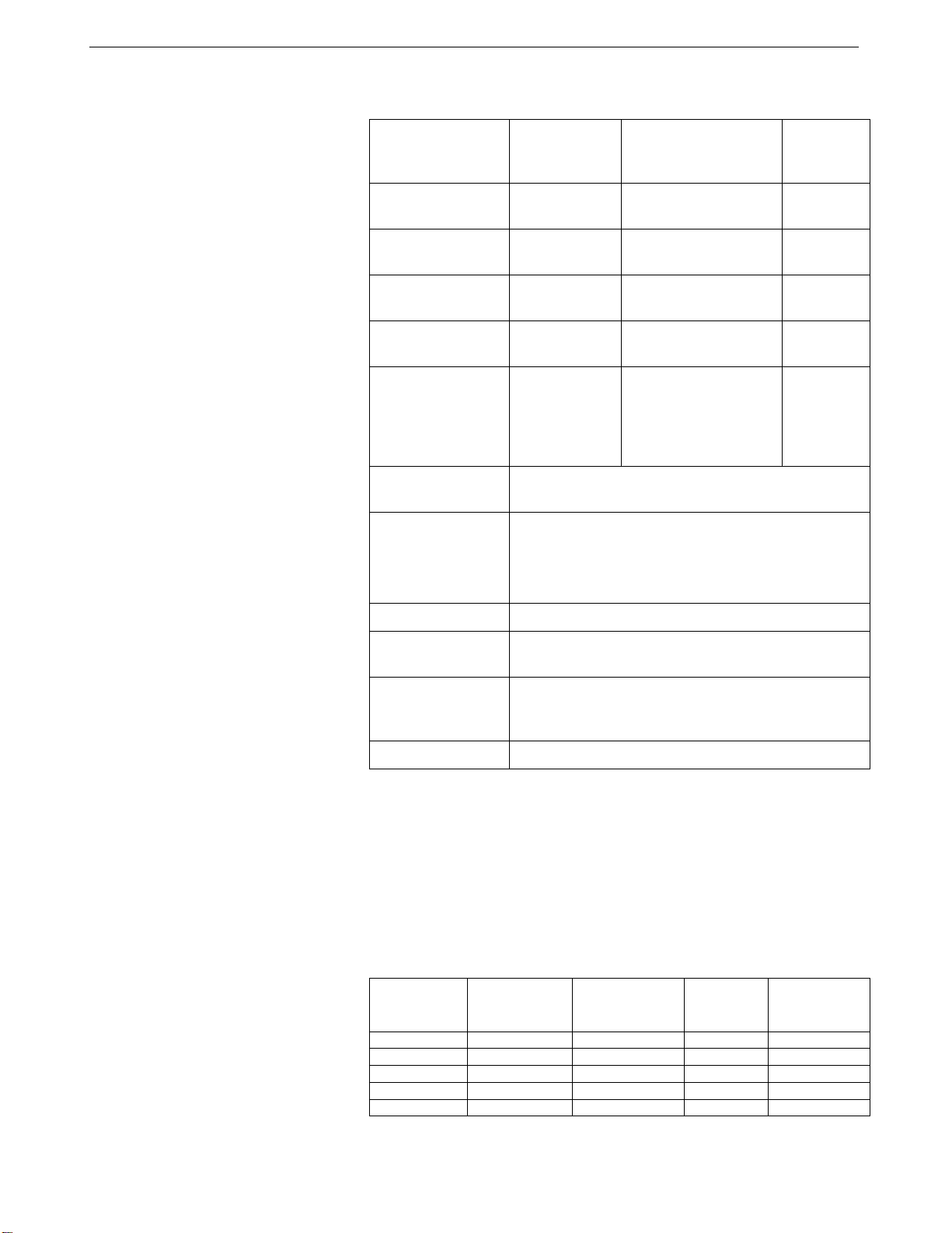
Specifications
Temperature
(°C)
1
Conductivity
(S/m)
Salinity
(PSU),
typical
Measurement
Range
Initial Accuracy
Typical Stability
(per month)
Resolution 2
Sensor
Calibration
Range
Counter
Time-Base
Input Power
Materials
Recommended
Flow Rate
-5 to +35
0.002
0.0002
0.0001
0 to 7
(0 to 70 mS/cm)
0.0003
(0.003 mS/cm)
0.0003
(0.003 mS/cm)
0.00001
(0.0001 mS/cm)
-
0.005
0.003
0.0002
0 to 6; physical
calibration over the
+1 to +32
range 2.6 to 6 S/m,
-
plus zero
conductivity (air)
Quartz TCXO, ±2 ppm per year aging;
±5 ppm vs. temperature (-5 to +30 °C)
8 - 30 VDC
Quiescent (sleep) Current: 10 microamps
Operating Current: 34 milliamps at 8 VDC
30 milliamps at 12-30 VDC
PVC housing
10 to 30 milliliters/second
(0.16 to 0.48 gallons/minute)
Maximum Safe
Operating
34.5 decibars (50 psi)
Pressure
Weight
4.6 kg (10.2 lbs)
Notes:
1
Temperature specifications above are for MicroTSG’s temperature sensor.
For optional remote temperature sensor (SBE 38), which can be integrated
with optional 90402 Interface Box Measurement range: -5 to +35 °C Initial accuracy: 0.001 °C
Resolution: 0.0003 °C Calibration: -1 to +32 °C
Typical stability: 0.001 °C in 6 months, certified
2
Resolution
Typical RMS noise with fixed resistors on temperature and conductivity inputs:
NCycles *
1 0.000190 0.000014 0.00027 0.00066
2 0.000170 0.000010 0.00016 0.00057
4 0.000150 0.000005 0.00015 0.00055
8 0.000087 0.000005 0.00009 0.00033
16 0.000078 0.000004 0.00007 0.00025
Temperature
(°C)
Conductivity
(S/m)
Salinity
(psu)
Sound
Velocity
(m/sec)
* NCycles = number of measurements to average per sample.
9
Page 18
Section 2: Description of MicroTSG SBE 45
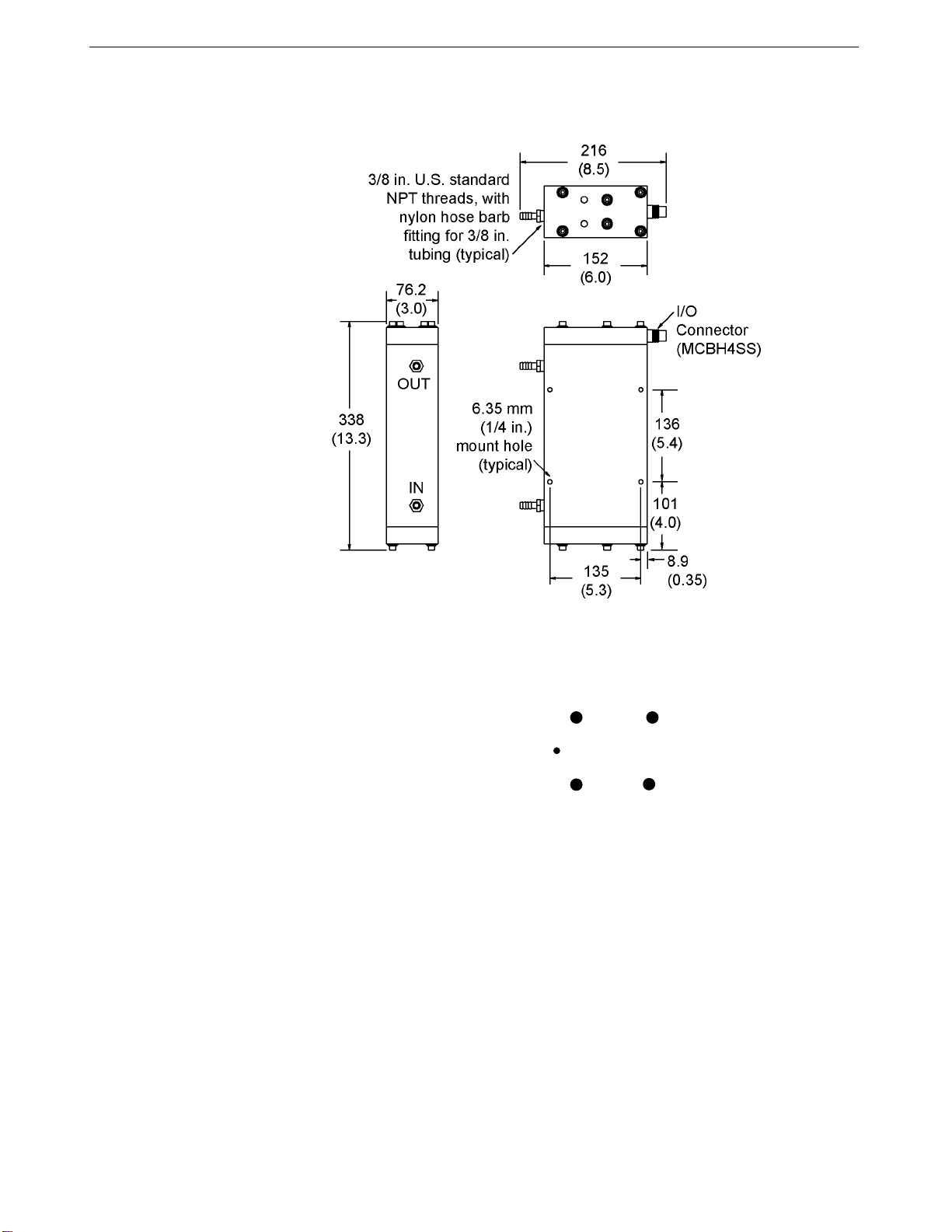
Dimensions and Connector
Dimensions in millimeters (inches)
15
MCBH4SS
Transmit Pin 3 Power Pin 4
Orientation Pin
Ground Pin 1
Receive Pin 2
Ground pin = Computer data common (pin 1)
Receive pin = RS-232C receive data transmitted from computer (pin 2)
Transmit pin = RS-232C transmit from MicroTSG to computer (pin 3)
Power pin = 8-30 VDC (pin 4)
10
Page 19
16
Section 2: Description of MicroTSG SBE 45
Sample Timing
The time to acquire the temperature and conductivity varies, depending on the
mode of operation.
Note:
See Command Descriptions in
Section 4: Setting Up MicroTSG
for descriptions of AutoRun=, Go,
SingleSample=, NCycles=, and
Interval=.
Notes:
• The time to transmit computed
parameters is dependent on baud
rate. See Baud Rate, Cable
Length, Power, and Data
Transmission Rate.
For autonomous sampling, if the
•
total time required for the sample
is greater than the user-input
sample interval (Interval=), the
MicroTSG begins the next sample
as soon as it finishes transmitting
the current sample.
Polled Sampling Mode
Polled Sampling Mode is in effect when:
• PCB J1 jumper is set to Normal or Autopower, AutoRun=N, and
sampling is started with Go (if SingleSample=Y) or with a polled
sampling command
Time from end of take sample command to beginning of reply (seconds)
= (NCycles * 0.1336) + 0.459
Autonomous Sampling Mode
Autonomous Sampling Mode is in effect when:
• PCB J1 jumper is set to Normal or Autopower, AutoRun=Y, and
SingleSample=N, or
• PCB J1 jumper is set to Normal (pins 2 and 3), AutoRun=N,
SingleSample=N, and sampling is started with Go
Time to acquire temperature and conductivity (seconds)
= (NCycles * 0.1336) + 0.287
Serial Line Sync Mode
Serial Line Sync Mode is in effect when:
• PCB J1 jumper set to Normal (pins 2 and 3), AutoRun=Y, and
SingleSample=Y
Time from wake-up to beginning of reply (seconds)
= (NCycles * 0.1336) + 1.643
Total Sampling Time
Once temperature and conductivity are acquired, the time to calculate the
desired parameters is not a function of the mode of operation:
• Time to compute temperature = 8.8 msec
• Time to compute conductivity = 15.4 msec
• Time to compute salinity = 83 msec
• Time to compute sound velocity = 35 msec
Total time required for sample =
time to acquire temperature and conductivity
+ time to compute selected parameters
+ time to transmit computed parameters
11
Page 20

Section 2: Description of MicroTSG SBE 45
Baud Rate, Cable Length, Power, and Data Transmission Rate
Baud Rate, Cable Length, and Data Transmission Rate
Notes:
• Baud rate is set with Baud=.
• Real-time output rate is set
with Interval=.
• Output format is set with
OutputCond=, OutputSal=, and
OutputSV=.
See Command Descriptions in
Section 4: Setting Up MicroTSG for
command details.
The rate that data can be transmitted from the MicroTSG is dependent on the
amount of data to be transmitted per scan and the serial data baud rate:
Time to transmit data =
(number of characters * 10 bits/character) / baud rate
where
Number of characters is dependent on the included data and output
format (see Data Output Format in Section 4: Setting Up MicroTSG).
Add 2 to the number of characters shown in the output format, to
account for the carriage return and line feed at the end of each scan.
Include decimal points, commas, and spaces when counting the
number of characters.
Note that the MicroTSG transmits data after it has completed the previous
sample and before it starts the next sample. See Sample Timing above for
information on sampling time.
The length of cable that the MicroTSG can drive to transmit real-time data is
also dependent on the baud rate. The allowable combinations are:
Maximum Cable Length (meters) Maximum Baud
800 1200
400 2400
200 4800 (factory set default)
100 9600
50 19200
25 38400
17
Example –
What is the minimum transmission time over 100 m of cable with OutputCond=Y, OutputSal=Y, OutputSV=Y, and
OutputFormat=0?
With 100 meters of cable, the MicroTSG requires a baud rate of 9600 or less.
Number of characters (from Data Output Format in Section 4: Setting Up MicroTSG) =
8 (T) + 2 (comma & space) + 8 (C) + 2 (comma & space) + 8 (salinity) + 2 (comma & space) + 8 (sound velocity)
+ 2 (carriage return & line feed) = 40
Time required to transmit data = (40 characters * 10 bits/character) / 9600 = 0.042 seconds = 42 msec
What is the minimum total time required per sample (Interval=), if averaging 4 measurements/sample (NCycles=4)
and operating in Autonomous Sampling Mode?
In Autonomous mode, time to acquire T and C (from Sample Timing above)
= (NCycles * 0.1336) + 0.287 = (4 * 0.1336) + 0.287 = 0.82 seconds
Total sampling time
= time to acquire T and C + time to compute parameters (from Sample Timing above) + time to transmit data
= 0.82 + (.0088 + .0154 + .083 + .035) + .042 = 1.00 second
Therefore, set Interval=1, transmitting 1 sample every second.
12
Page 21
18
Section 2: Description of MicroTSG SBE 45
Power and Cable Length
Note:
Common wire resistances:
Gauge Resistance (ohms/foot)
12 0.0016
14 0.0025
16 0.0040
18 0.0064
19 0.0081
20 0.0107
22 0.0162
24 0.0257
26 0.0410
28 0.0653
There are two issues to consider:
• Limiting the IR loss to 1 volt; higher IR loss will prevent the
instrument from transmitting real-time data because of the difference in
ground potential.
• Supplying enough power at the power source so that sufficient power is
available at the instrument after considering IR loss.
Looking at each issue separately:
Limiting IR Loss to 1 Volt
The limit to cable length is typically reached when the maximum current times
the power common wire resistance is more than 1 volt, because the difference
in ground potential of the MicroTSG and ground controller prevents the
MicroTSG from transmitting real-time data.
= 1 volt = IR
V
limit
limit
Where I is the current required by the MicroTSG (34 milliamps at 8 VDC;
see Specifications above).
Maximum cable length = R
/ wire resistance per foot
limit
Example – For 18 gauge wire, what is the maximum distance to transmit power to the MicroTSG?
If this the controlling factor for maximum cable length if wanting to transmit at 1200 baud?
For 34 milliamp current, R
For 18 gauge wire, resistance is 0.0064 ohms/foot.
Therefore, maximum cable length is 29 ohms / 0.0064 ohms/foot = 4531 feet = 1381 meters.
Note that 1381 meters > 800 meters (maximum distance MicroTSG can transmit data at 1200 baud), so IR loss is not
controlling factor for this example.
Example 2 – Same as above, but there are 4 MicroTSGs powered from the same power supply.
R
= V
limit
Therefore, maximum cable length is 7.35 ohms / 0.0064 ohms/foot = 1148 feet = 350 meters (this is cable length to
MicroTSG furthest from power source).
/ I = 1 volt / (0.034 amps * 4 MicroTSGs) = 7.35 ohms
limit
limit
= V
/ I = 1 volt / 0.034 amps = 29 ohms
limit
Supplying Enough Power to MicroTSG
Another consideration in determining maximum cable length is supplying
enough power at the power source so that sufficient voltage is available, after
the IR loss in the cable, to power the MicroTSG.
Example – For 18 gauge wire, what is the maximum distance to transmit power to the MicroTSG if using a 8.5 volt power
source to supply power?
Is this the controlling factor for maximum cable length if wanting to transmit at 1200 baud?
MicroTSG’s input power specification is 8 – 30 volts. Therefore, a 0.5 volt IR drop (8.5 volts – 8 volts) would still provide
enough power to MicroTSG.
V = IR 0.5 volts = (.034 amps) * (0.0064 ohms/foot * cable length) Cable length = 2297 ft = 700 meters
Note that 700 meters < 800 meters (maximum distance MicroTSG can transmit data at 1200 baud), so IR drop in power
is controlling factor for this example. Using a higher voltage power supply or a different wire gauge (12, 14, or 16 gauge)
would provide sufficient power at MicroTSG to allow an 800 meter cable length.
Example 2 – Same as above, but there are 4 MicroTSGs powered from the same power supply.
V = IR 0.5 volts = (.034 amps * 4 MicroTSGs) *(0.0064 ohms/foot * cable length)
Cable length = 574 ft = 175 meters (this is cable length to MicroTSG furthest from power source).
13
Page 22

Section 2: Description of MicroTSG SBE 45
Remote Temperature Sensor (optional)
The optional 90402 – SBE 45 Power, Navigation, and Remote Temperature
Notes:
• See the Interface Box manual for
operation of the MicroTSG with
the Interface Box. The Interface
Box can be added to the system
at any time, and does not
need to be part of the original
MicroTSG order.
• Sea-Bird software (Seasave realtime data acquisition and SBE
Data Processing’s Data
Conversion and Derive modules)
uses the data from the
MicroTSG’s temperature and
conductivity sensors to calculate
salinity, and then uses that
salinity with the temperature from
the remote temperature sensor
to calculate density and
sound velocity.
Interface Box can append the output of an optional SBE 38 temperature sensor
to the output from the MicroTSG. Often, the MicroTSG is mounted in the
interior of the vessel. In this configuration the recorded conductivity is correct,
but the water temperature has changed as it has passed through the plumbing
system. The remote temperature sensor can be placed in a location that
provides more accurate measurement of the sea surface water temperature.
The ideal location for the remote sensor is at the seawater intake (before
the pump) near the bow of the ship. This minimizes contamination of the
surface temperature measurement by the ship’s own thermal mass.
To compute salinity, always use the data from the temperature sensor on
the MicroTSG, not from the remote temperature sensor. Conductivity has
a strong thermal coefficient; therefore, it is critical to know the temperature of
the water when the conductivity sensor samples it in order to compute salinity
correctly. On a typical installation, there may be 20 to 30 meters of plumbing
between the remote temperature sensor and the MicroTSG. As the water flows
through the pipes it changes temperature dramatically, making the data from
the remote temperature sensor an inaccurate representation of the temperature
when the water reaches the conductivity sensor. Use the remote temperature
sensor only to report surface temperature, and to calculate density and
sound velocity (density and sound velocity are a function of salinity
and temperature).
19
14
Page 23
20
Section 3: Installing System SBE 45
Section 3: Installing System
This section provides information on:
• Software installation
• System schematic and installation guidelines
• Power-up mode jumper setting check
• MicroTSG installation
Installing Software
Sea-Bird recommends the following minimum system requirements for
Notes:
• Help files provide detailed
information on the software.
Separate software manuals on the
CD-ROM contain detailed
information on Seasave V7 and
SBE Data Processing.
• Sea-Bird also supplies an older
version of Seasave, SeasaveWin32. However, all Seasave
instructions in this manual are
written for Seasave V7. See
Seasave-Win32’s manual and/or
Help files if you prefer to use the
older software.
• It is possible to use the MicroTSG
without the SEATERM terminal
program by sending direct
commands from a dumb terminal or
terminal emulator, such as Windows
HyperTerminal.
• Sea-Bird supplies the current
version of our software when you
purchase an instrument. As software
revisions occur, we post the revised
software on our FTP site. See our
website (www.seabird.com) for the
latest software version number, a
description of the software changes,
and instructions for downloading the
software from the FTP site.
installing the software: Windows 2000 or later, 500 MHz processor,
256 MB RAM, and 90 MB free disk space for installation. Although
SEASOFT V2 was designed to work with a PC running Win 2000/XP;
extensive testing has not shown any compatibility problems when using the
software with a PC running Windows Vista.
If not already installed, install Sea-Bird software programs on your computer
using the supplied software CD.
1. Insert the CD in your CD drive.
2. Install software: Double click on SeasoftV2_date.exe (date is the date that
version of the software was created). Follow the dialog box directions to
install the software. The installation program allows you to install the
desired components. Install all the components, or just install
SEATERM (terminal program), Seasave V7 (real-time data acquisition),
and SBE Data Processing (data processing).
The default location for the software is c:\Program Files\Sea-Bird. Within that
folder is a sub-directory for each component.
15
Page 24
Section 3: Installing System SBE 45
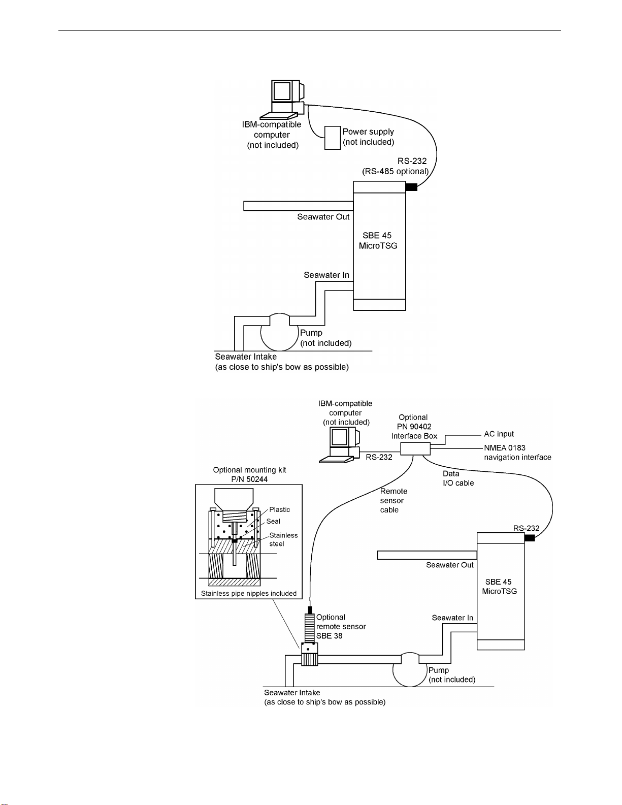
System Schematic and Installation Guidelines
21
MicroTSG with Optional PN 90402 Interface Box,
SBE 38 Remote Temperature Sensor, and
NMEA Navigation Device
(see PN 90402 – SBE 45 Power, Navigation, and Remote
Temperature Interface Box manual for operating details)
16
Page 25
22
Section 3: Installing System SBE 45
Sea-Bird does not provide detailed installation instructions for the MicroTSG,
given the unique nature of every ship and type of installation. The installation
of the MicroTSG should be done by qualified shipfitters, with the oversight of
a competent ship designer or naval architect. Consider the following:
• The MicroTSG can be mounted anywhere it will fit that is accessible for
maintenance and cleaning. For safety, mount the MicroTSG above the
water line.
Note:
The optional Interface Box appends
data from the optional SBE 38
remote temperature sensor to the
MicroTSG data stream.
¾ If the remote temperature sensor is not used, mount the MicroTSG as
close to the seawater intake as possible to avoid thermal
contamination from long plumbing runs. Thermal contamination will
not affect salinity accuracy, but the MicroTSG will report the
temperature of the water when it reaches the instrument.
¾ If the remote temperature sensor is used, the MicroTSG can be
mounted in the ship’s lab or other convenient location.
• Sea-Bird does not recommend or supply a pump.
¾ The pump must provide 10 to 30 milliliter/second
(0.16 to 0.48 gallons/minute) flow.
¾ Pressure at the MicroTSG is limited to 34.5 decibars (50 psi).
¾ Research vessels often maintain seawater delivery systems for a
variety of scientific purposes, including feed to a thermosalinograph.
Many vessels use engine raw cooling water. However, because the
MicroTSG is designed for a flow rate of 10 to 30 milliliters/second,
ensure that most of the coolant flow bypasses the MicroTSG.
¾ Pleasure-boat pumps designed for salt water and for below-fluid level
(non-priming) may be satisfactory, although their flow rates are much
too high (more than 15 gallons/minute). Some method – flow
restricting orifice, bypass, etc. – is needed to reduce the flow rate to
the required level. Additionally, pleasure-boat pumps are not usually
certified for below-waterline use.
• Bubbles in the plumbing of a flow-through system are a common problem
and will cause noisy salinity data. To minimize bubbles:
¾ Place the pump below the water line to push rather than lift the water.
¾ Locate the MicroTSG’s hull intake as deep as possible, as far as
possible from bubble sources (bow wake, propeller, etc.).
• Depending on the chosen design of a permanent seawater supply
(including pump, intake fitting, pipes, etc.), a de-bubbling device may be
needed to separate bubbles from the water before it enters the MicroTSG.
Note that a de-bubbler may cause additional temperature errors for the
MicroTSG’s primary temperature sensor; salinity accuracy (and accuracy
of an optional remote temperature sensor) is not affected. Not all ships
require de-bubblers, but many do for best quality salinity data. Large
single point salinity spikes can be removed with the Wild Edit module in
SBE Data Processing.
• Route cabling as cleanly as possible, avoiding sources of noise. Electric
motors are a particular problem. Avoid routing the cable next to
generators and air conditioners. Cables longer than 3 meters should be
installed inside an earthed metal conduit by a qualified electrician. This
minimizes the potential for external signals to disrupt communication and
ensures that high voltage lines (such as the sea cable) are sufficiently
protected. Cables shorter than 3 meters can be used without shielding
when installing or bench testing the instrument.
• If practical, mount the optional SBE 38 remote temperature sensor outside
the hull. However, the SBE 38 is usually mounted in the remote sensor
mount kit, which has 1-inch pipe threads on each end; plumb the mount kit
into your seawater system. Install the SBE 38 as close to the seawater intake
as possible (before the pump), near the bow of the ship. Since the
installation is below the water line, consult your ship’s engineer / naval
architect / shipyard regarding the actual installation. We cannot offer advice
in this matter as each ship is different and plumbing regulations vary.
17
Page 26
Section 3: Installing System SBE 45
Power-Up Jumper Check
The MicroTSG’s Printed Circuit Board (PCB) has a jumper that controls how
the MicroTSG wakes up:
• Autopower (default) – The MicroTSG wakes up when power is applied.
System capability is dependent on the external wiring configuration:
¾ Three wires – This configuration is useful in simple systems where
Note:
For a three-wire external wiring
configuration, or to use the MicroTSG
with the Interface Box, set:
• J1 jumper to Autopower
• AutoRun=Y, and
• SingleSample=N
See Section 4: Setting Up MicroTSG.
Note:
See Appendix II: Electronics
Disassembly/Reassembly for details
on accessing the PCB to change the
jumper setting.
• Normal – The MicroTSG wakes up when there is a pulse on the serial
Verify the jumper setting in one of the following ways:
• Check the Configuration Sheet (in the manual) for the factory setting, or
• Connect the MicroTSG to the computer as described in Communications
a controller applies power, waits for data, and then removes
power. Only three of the four wires (Power, Ground, and Transmit)
are needed for operation, since it is not necessary to command the
MicroTSG to take samples. Note that the MicroTSG does not
respond to any commands in this configuration, so initial setup
of the system must be performed with all four wires in place
(see Command Descriptions in Section 4: Setting Up MicroTSG).
¾ Four wires – With all four wires (Power, Ground, Receive, and
Transmit), the MicroTSG can receive and respond to most
commands. Note that the MicroTSG does not respond to QS in
this configuration.
interface lines. In this configuration, the MicroTSG can be controlled
using the documented commands and can be commanded into a quiescent
(sleep) state with QS.
Test and Setup in Section 4: Setting Up MicroTSG. Set the appropriate
communications settings, wake up the MicroTSG with the Connect button
on SEATERM’s Toolbar, and then enter QS after the S> prompt.
The response indicates whether the jumper is in the Normal or
Autopower configuration:
¾ Autopower – system returns S> prompt, indicating that the
MicroTSG is not in quiescent (sleep) state.
¾ Normal – system does not return S> prompt, indicating that the
MicroTSG is in quiescent (sleep) state.
23
18
Page 27
24
Section 3: Installing System SBE 45
Installing MicroTSG
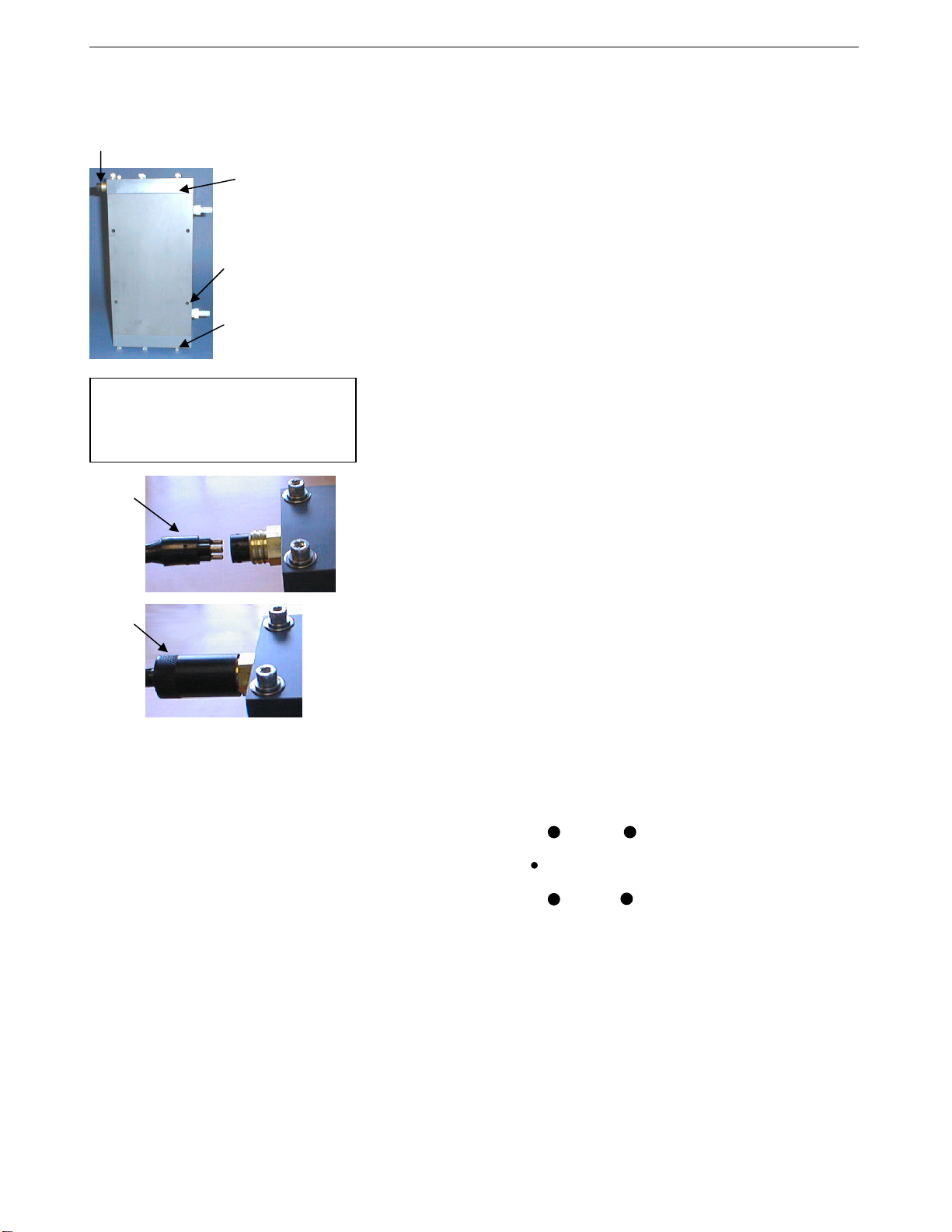
Electrical
connector
Top plate
Bolt hole
(typical)
Bottom plate
CAUTION:
Do not use WD-40 or other
petroleum-based lubricants, as they
will damage the connector.
I/O
cable
connector
Locking
sleeve
1. New MicroTSGs are shipped with an AF24173 Anti-Foulant Device preinstalled. Verify that the Anti-Foulant Device is in the anti-foulant device
cup (see Section 6: Routine Maintenance and Calibration for access to
and replacement of the Anti-Foulant Device).
2. Mount the MicroTSG, with the electrical connector at the top, using the
1
/4-inch bolt holes on the sides. Provide clearance as follows:
four
• Bottom — 152 mm (6 inches) clearance for removal of the
bottom plate, to allow access for replacing the AF24173 Anti-Foulant
Device and cleaning.
• Top — 305 mm (12 inches) clearance for removal of the top plate, to
allow access for removing sensors and electronics.
• Sides — small clearance by using washers with the mounting
hardware, to prevent binding when removing the top or bottom plate.
3. Install the I/O cable:
A. Lightly lubricate the sides of the rubber prongs on the cable connector
with silicone grease (DC-4 or equivalent).
B. Install the cable connector, aligning the long pin with the small hole
on the MicroTSG’s bulkhead connector.
C. Place the locking sleeve over the connector. Tighten the sleeve finger
tight only. Do not overtighten the locking sleeve and do not use a
wrench or pliers.
4. Install the piping connections to the MicroTSG. The housing is tapped
3
/8-inch U.S. standard NPT threads. Nylon hose barb fittings for
with
3
/8-inch tubing are provided.
5. Verify that the hardware and external fittings are secure.
6. For use without optional Interface Box: Connect the MicroTSG to the
computer and power supply.
• Connect the I/O cable connector to your computer’s serial port.
• Connect the I/O cable connector’s red (+) and black (-) wires to a
power supply (8-30 VDC).
Transmit Pin 3 Power Pin 4
Orientation Pin
Ground Pin 1
Receive Pin 2
Ground pin: Computer data common (pin 1)
Receive pin: RS-232C receive data transmitted from computer (pin 2)
Transmit pin: RS-232C transmit from MicroTSG to computer (pin 3)
Power pin: 8-30 VDC (pin 4)
7. For use with optional Interface Box: See schematic in System Schematic
and Installation Guidelines above, and see PN 90402 – SBE 45 Power,
Navigation, and Remote Temperature Interface Box manual.
19
Page 28
Section 4: Setting Up MicroTSG SBE 45
S
Section 4: Setting Up MicroTSG
This section provides information on:
• MicroTSG setup
• Sampling modes and example sets of operation commands
• Timeout description
• Command descriptions
• Data output format
• Setting up configuration (.xmlcon or .con) file for real-time data
acquisition and data processing
Communications Test and Setup
The power and communications test will verify that the system works,
prior to deployment.
Note:
See SEATERM’s Help files.
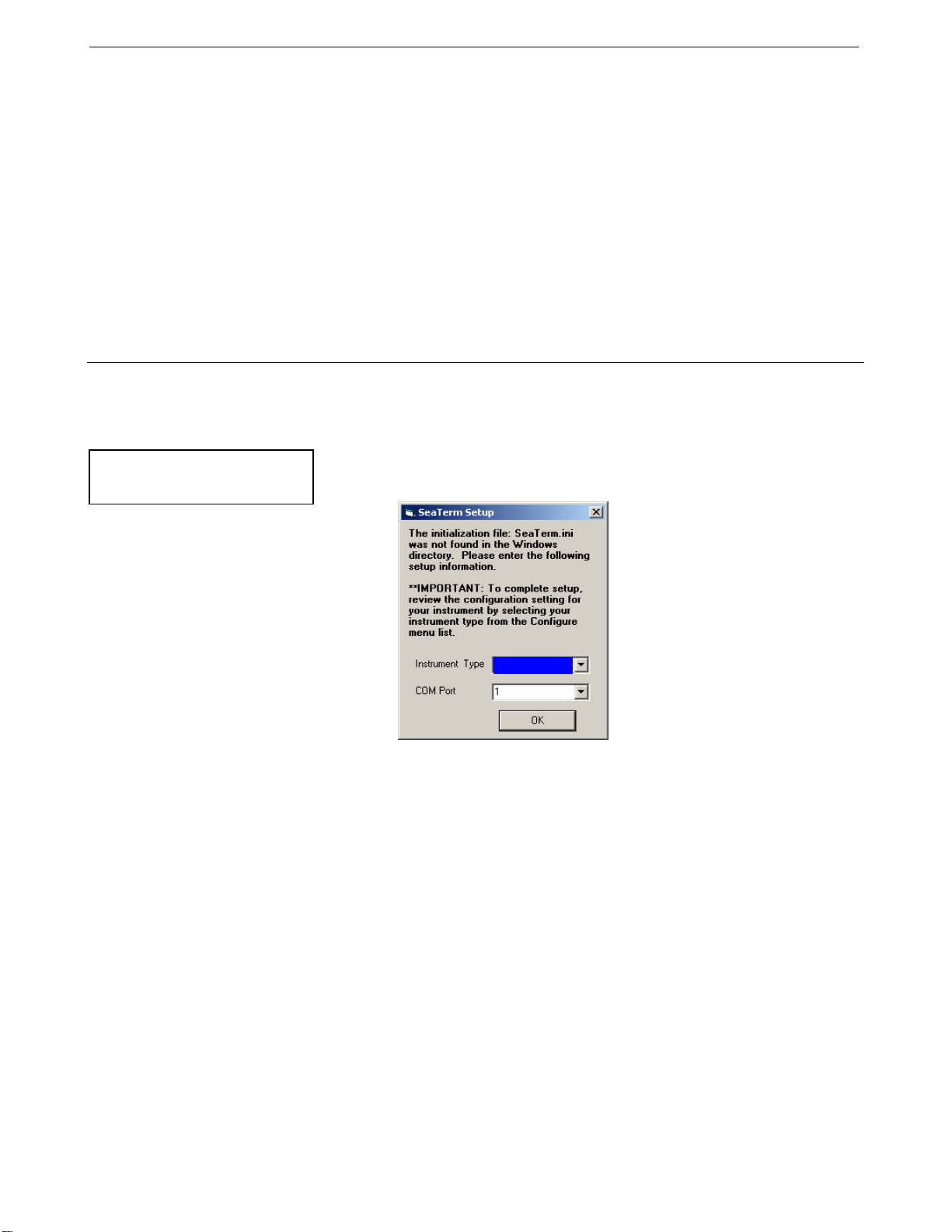
1. Double click on Seaterm.exe. If this is the first time the program is used,
the configuration dialog box may appear:
25
BE45
Select the instrument type (SBE 45) and the computer COM port for
communication with the MicroTSG. Click OK.
20
Page 29
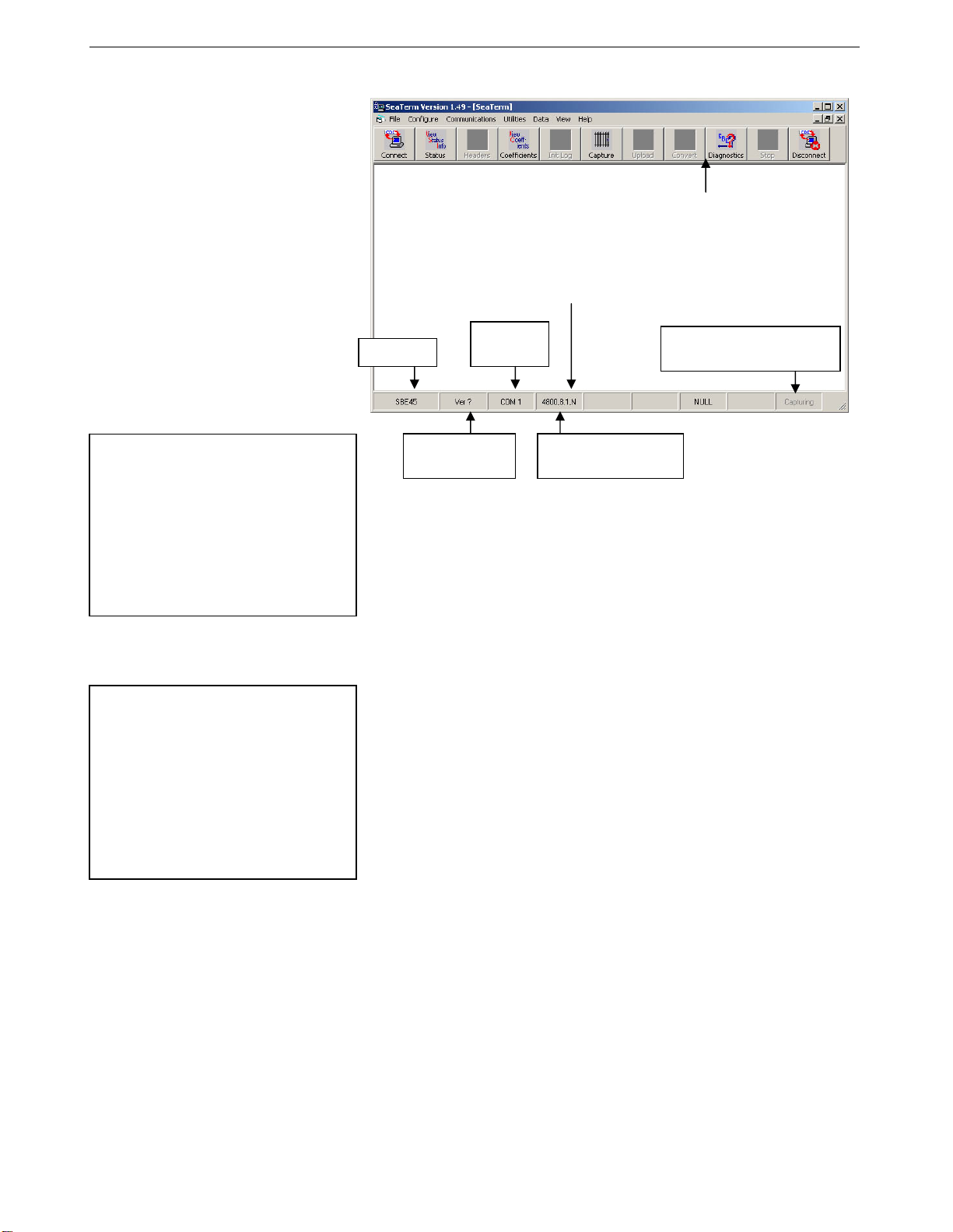
26
Section 4: Setting Up MicroTSG SBE 45
2. The main screen looks like this:
Menus
Toolbar
Command/Data Echo Area
Status bar
Note:
There is at least one way, and as
many as three ways, to enter
a command:
• Manually type a command in
Command/Data Echo Area
• Use a menu to automatically
generate a command
• Use a Toolbar button to
automatically generate a command
Note:
Once the system is configured and
connected (Steps 3 through 5), to
update the Status bar:
• on the Toolbar, click Status; or
• from the Utilities menu, select
Instrument Status.
SEATERM sends the status command,
which displays in the Command/Data
Echo Area, and updates the
Status bar.
Instrument
EPROM version
Instrument
Computer
COM port
Baud rate, data bits,
stop bits, and parity
Capture to file status – grayed
out if not capturing
• Menus – Contains tasks and frequently executed instrument
commands.
• Toolbar – Contains buttons for frequently executed tasks and
instrument commands. All tasks and commands accessed through the
Toolbar are also available in the Menus. To display or hide the
Toolbar, select View Toolbar in the View menu. Grayed out Toolbar
buttons are not applicable.
• Command/Data Echo Area – Echoes a command executed using a
Menu or Toolbar button, as well as the instrument’s response.
Additionally, a command can be manually typed in this area, from the
available commands for the instrument. Note that the instrument must
be ‘awake’ for it to respond to a command (use Connect on the
Toolbar to wake up the instrument).
• Status bar – Provides status information. To display or hide the Status
bar, select View Status bar in the View menu.
21
Page 30
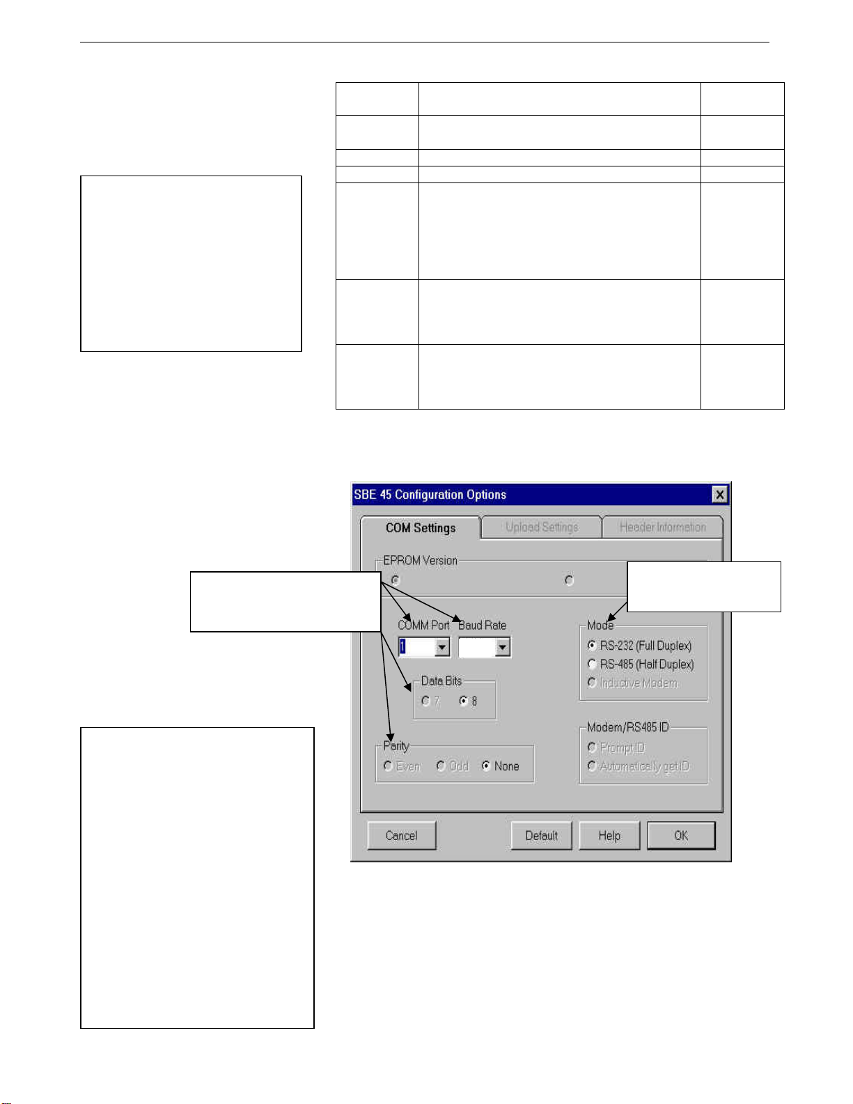
Section 4: Setting Up MicroTSG SBE 45
4
Following are the Toolbar buttons applicable to the MicroTSG:
Note:
.cap file created by SEATERM is
not compatible with our postprocessing software (SBE Data
Processing). Instead of using
SEATERM’s capture utility, use
Seasave (our real-time data
acquisition software) to create a
.hex file that is compatible with
SBE Data Processing
(see Section 5: Operating System).
Toolbar
Buttons
Connect
Re-establish communications with MicroTSG.
Computer responds with S> prompt.
Description
Status Display instrument status.
Coefficients Display calibration coefficients.
Capture instrument responses on screen to file.
File has .cap extension. Click Capture again to
Capture
turn off capture. Capture status displays in Status
bar. As MicroTSG has no internal memory, you
must capture before sampling begins to save data
for future review and processing.
Perform one or more diagnostic tests on
Diagnostics
MicroTSG. Diagnostic test(s) accessed in this
manner are non-destructive – they do not write
over any existing instrument settings.
Equivalent
Command*
(press Enter
key)
DS
DC
—
DS, DC, TS,
and TSR
Free computer COM port used to communicate
Disconnect
with MicroTSG. COM port can then be used by
another program. Note that MicroTSG must be
—
connected to COM port for data to be obtained.
*See Command Descriptions.
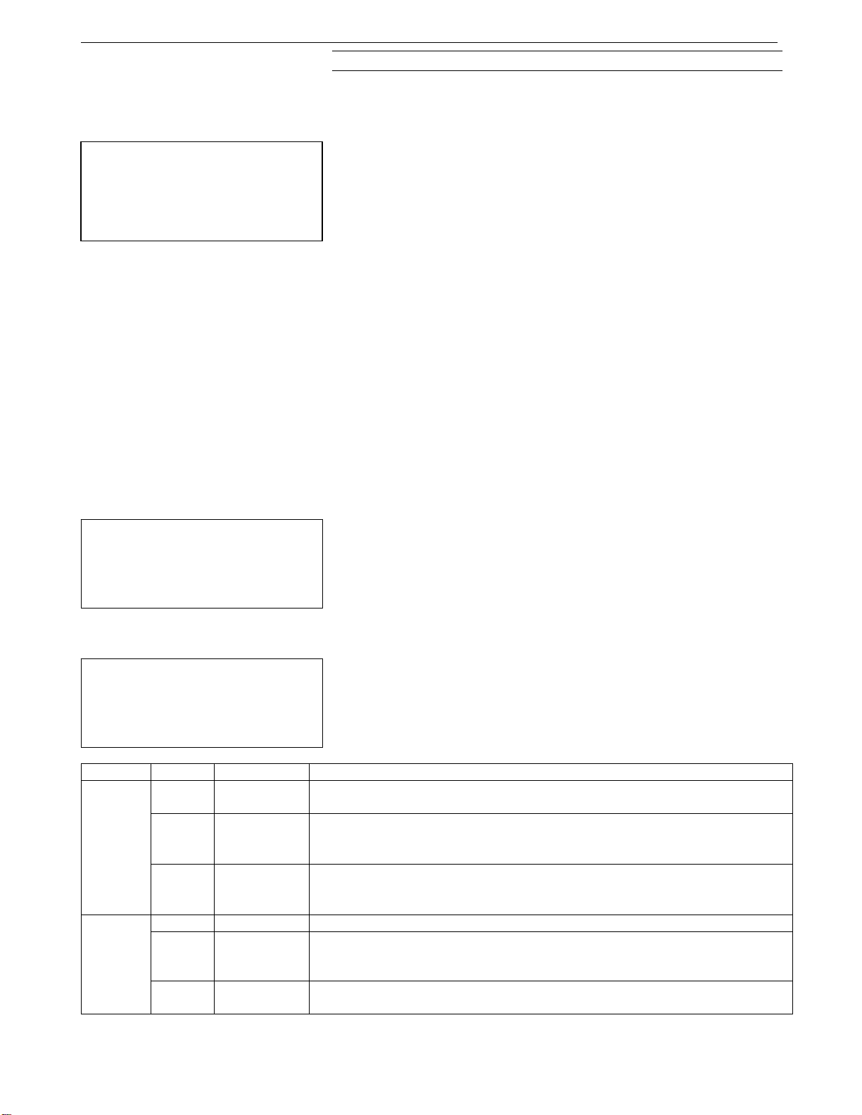
3. In the Configure menu, select SBE 45 TSG. The dialog box looks
like this:
27
Computer COM port, baud rate,
data bits, and parity for
communication between computer
and MicroTSG.
Note:
• SEATERM’s baud rate must be the
same as the MicroTSG baud rate
(set with Baud=). Baud is factoryset to 4800, but can be changed by
the user (see Command
Descriptions).
• When you click OK, SEATERM
saves the Configuration Options
settings to the SeaTerm.ini file in
your Windows directory.
SeaTerm.ini contains the last saved
settings for each instrument. When
you open SEATERM and select the
desired instrument (SBE 37, 45,
etc.) in the Configure menu, the
Configuration Options dialog box
shows the last saved settings for
that instrument.
Interface for communication
between computer and
MicroTSG.
800
Make the selections in the Configuration Options dialog box:
• COMM Port: COM 1 through COM 10, as applicable
• Baud Rate: 4800 (documented on Configuration Sheet in manual)
• Data Bits: 8
• Parity: None
• Mode: RS-232 (Full Duplex)
Click OK to save the settings.
22
Page 31

28
Section 4: Setting Up MicroTSG SBE 45
4. In the Communications menu, select Options / Cycle baud
when connecting.
5. Click Connect on the Toolbar. SEATERM tries to connect to the
MicroTSG at the baud set in Step 3. If it cannot, it cycles through all other
possible baud rates to try to connect. When it connects, the display looks
like this:
S>SBE45 V 1.1b
S>
This shows that correct communications between the computer and
MicroTSG has been established. If the system does not respond as shown:
• Click Connect again.
• Verify the correct instrument was selected in the Configure menu and
the settings were entered correctly in the Configuration Options
dialog box.
• Check cabling between the computer and MicroTSG.
6. Display MicroTSG status information by clicking Status on the Toolbar.
The display looks like this:
SBE45 V 1.1b SERIAL NO. 1258
not logging data
sample interval = 30 seconds
output conductivity with each sample
do not output salinity with each sample
do not output sound velocity with each sample
do not start sampling when power on
do not power off after taking a single sample
do not power off after two minutes of inactivity
A/D cycles to average = 4
7. Command the MicroTSG to take a sample by typing TS and pressing the
Enter key. The display looks like this (if output conductivity with each
sample, do not output salinity with each sample, and do not output sound
velocity with each sample displayed in response to the status command in
Step 6) :
23.7658, 0.00019
where 23.7658 = temperature in degrees Celsius
0.00019 = conductivity in S/m
These numbers should be reasonable; i.e., room temperature and
zero conductivity.
8. Establish the sampling scheme, after reviewing the information in this
section on sampling modes and commands.
9. Command the MicroTSG to go to sleep (quiescent state) by typing QS
and pressing the Enter key. The response indicates whether the PCB’s J1
jumper is in the Normal or Autopower configuration:
Notes:
• See Power-Up Jumper Check in
Section 3: Installing System
for a description of Autopower
and Normal.
• See Appendix II: Electronics
Disassembly/Reassembly to access
the PCB and move the jumper.
• Autopower – system returns S> prompt.
• Normal – system does not return S> prompt.
If necessary, remove the PCB and move the jumper to the desired pins.
The MicroTSG is ready for deployment.
23
Page 32

Section 4: Setting Up MicroTSG SBE 45
Sampling Modes
The MicroTSG has three basic sampling modes for obtaining data: Polled
Sampling, Autonomous Sampling, and Serial Line Synchronization Sampling.
However, commands and the J1 jumper setting on the MicroTSG’s PCB
can be used in various combinations to provide a high degree of
operating flexibility.
Shown below are descriptions and examples of the three basic sampling
modes. Note that the MicroTSG’s response to each command is not shown in
the examples. Review the operation of the basic sampling modes and the
commands described in Command Descriptions before setting up your system.
Polled Sampling
Note:
After waking the MicroTSG, you may
need to press the Enter key several
times and send Stop to interrupt
sampling, depending on how the
instrument was set up the last time it
was used.
On command, the MicroTSG takes one sample of data and sends the data to
the computer.
Examples: Polled Sampling Mode (user input in bold)
Example 1: J1 jumper in Normal position (pins 2 and 3).
Wake up MicroTSG. Set up to wait for command each time MicroTSG
wakes up, and send salinity with data. Send status command to verify
setup. Send power-off command after all parameters are entered.
Assuming that power is always applied:
(Click Connect on Toolbar to wake up.)
S>AUTORUN=N
S>OUTPUTSAL=Y
S>DS (to verify setup)
S>QS
When ready to take a sample (repeat as desired): wake up MicroTSG,
command it to take a sample and output converted data to computer, and
send power-off command.
(Before first sample, click Capture on Toolbar to capture data to a file – program
requests file name for data to be stored.)
(Click Connect on Toolbar to wake up.)
S>TS
S>QS
Example 2: J1 jumper in Autopower position (pins 1 and 2).
Wake up MicroTSG. Set up to wait for command each time MicroTSG
wakes up, and send salinity with data. Send status command to verify
setup. Remove power after all parameters are entered.
(Apply power to wake up.)
S>AUTORUN=N
S>OUTPUTSAL=Y
S>DS (to verify setup)
(Remove power.)
When ready to take a sample (repeat as desired): wake up MicroTSG,
command it to take a sample and output converted data to computer, and
remove power.
(Before first sample, click Capture on Toolbar to capture data to a file – program
requests file name for data to be stored.)
(Apply power to wake up.)
S>TS
(Remove power.)
29
24
Page 33

30
Section 4: Setting Up MicroTSG SBE 45
Autonomous Sampling
Notes:
• After waking the
MicroTSG, you may
need to press the Enter
key several times and
send Stop to interrupt
sampling, depending on
how the instrument was
set up the last time it
was used.
• If using the MicroTSG
with the Interface Box,
set up the MicroTSG to
operate in autonomous
sampling mode:
¾ J1 jumper in
Autopower position
(pins 1 and 2)
¾ AutoRun=Y
¾ SingleSample=N
Examples: Autonomous Sampling Mode (user input in bold)
Example 1: J1 jumper in Normal position (pins 2 and 3), AutoRun=Y.
Set up to take a sample every 20 seconds. Send status command to verify setup. Send power-off
command after all parameters are entered. Assuming that power is always applied:
(Click Connect on Toolbar to wake up.)
S>SINGLESAMPLE=N
S>INTERVAL=20
S>AUTORUN=Y
S>DS (to verify setup)
S>QS
When ready to begin sampling:
(Click Capture on Toolbar to capture data to a file – program requests file name for data to be stored.)
(Click Connect on Toolbar to wake up – sampling begins automatically.)
When ready to stop sampling and go to sleep:
(Press Enter key to get S> prompt.)
S>STOP
S>QS
Example 2: J1 jumper in Normal position (pins 2 and 3), AutoRun=N.
Set up to take a sample every 20 seconds. Send status command to verify setup. Send power-off
command after all parameters are entered. Assuming that power is always applied:
(Click Connect on Toolbar to wake up.)
S>SINGLESAMPLE=N
S>INTERVAL=20
S>AUTORUN=N
S>DS (to verify setup)
S>QS
When ready to begin sampling:
(Click Capture on Toolbar to capture data to a file – program requests file name for data to be stored.)
(Click Connect on Toolbar to wake up.)
S>GO
When ready to stop sampling and go to sleep:
(Press Enter key to get S> prompt.)
S>STOP
S>QS
Example 3: J1 jumper in Autopower position (pins 1 and 2).
Set up to take a sample every 20 seconds. Send status command to verify setup. Remove power
after all parameters are entered.
(Apply power to wake up.)
S>SINGLESAMPLE=N
S>INTERVAL=20
S>AUTORUN=Y
S>DS (to verify setup)
(Remove power.)
When ready to begin sampling:
(Click Capture on Toolbar to capture data to a file – program requests file name for data to be stored)
(Apply power to wake up; sampling begins automatically.)
When ready to stop sampling:
(Remove power.)
To change the setup:
(Apply power to wake up; sampling begins automatically. Press Enter key several times to get S> prompt.)
S>STOP
S> (send desired commands)
(Remove power.)
The MicroTSG samples data at pre-programmed intervals, defined by
Interval=, and sends the data to the computer. The MicroTSG does not enter
quiescent (sleep) state between samples.
25
Page 34

Section 4: Setting Up MicroTSG SBE 45
Serial Line Synchronization (Serial Line Sync)
Note:
After waking the MicroTSG, you may
need to press the Enter key several
times and send Stop to interrupt
sampling, depending on how the
instrument was set up the last time it
was used.
In Serial Line Sync Mode, a simple pulse (a single character) on the RS-232
line causes the MicroTSG to wake up, take and output a single sample, and
automatically go to sleep (enter quiescent state). This mode is enabled if
AutoRun=Y, SingleSample=Y, and the PCB’s J1 jumper is in the
Normal position (pins 2 and 3).
Example: Serial Line Sync Mode (user input in bold)
(J1 jumper in Normal position – pins 2 and 3)
Set up to take a sample upon receipt of any character and then
automatically go to sleep. Send status command to verify setup. Send
power-off command to MicroTSG after all parameters are entered –
system automatically wakes up and goes to sleep for each sample upon
receipt of a character. Assuming that power is always applied:
(Click Connect on Toolbar to wake up.)
S>SINGLESAMPLE=Y
S>AUTORUN=Y
S>DS (to verify setup)
S>QS
When ready to take a sample (repeat as desired):
(Before first sample, click Capture on Toolbar to capture data to a file – program
requests file name for data to be stored)
(Press Enter key to wake up, sample, and go to sleep.)
When ready to stop sampling or change setup:
(Press Enter key several times to get S> prompt)
S>STOP
S> (Enter desired commands)
S>QS
31
Timeout Description
The MicroTSG has a timeout algorithm when jumpered in the Normal
configuration (PCB J1 pins 2 and 3). If the MicroTSG does not receive a
command or sample data for two minutes and AutoOff=Y, it powers down its
communication circuits. This places the MicroTSG in quiescent state, drawing
minimal current. To re-establish control (wake up), click Connect on the
Toolbar or press the Enter key. The system responds with the S> prompt.
26
Page 35

32
Section 4: Setting Up MicroTSG SBE 45
Command Descriptions
This section describes commands and provides sample outputs.
See Appendix III: Command Summary for a summarized command list.
When entering commands:
• Input commands to the MicroTSG in upper or lower case letters and
register commands by pressing the Enter key.
• The MicroTSG sends ? CMD if an invalid command is entered.
• If the system does not return an S> prompt after executing a command,
press the Enter key to get the S> prompt.
• If in quiescent state, re-establish communications by clicking Connect on
the Toolbar or pressing the Enter key to get an S> prompt.
Status Command
DS Display operating status and setup parameters.
Equivalent to Status on Toolbar.
List below includes, where applicable,
command used to modify parameter.
• Firmware version and serial number
• Logging status -
logging data,
logging data, not
or unknown status
• Sample interval time [Interval=]
• Output conductivity with each sample
[OutputCond=]?
• Output salinity with each sample
[OutputSal=]?
• Output sound velocity with each sample
[OutputSV=]? If yes, sound velocity
algorithm [SVAlgorithm=].
• Start sampling automatically when power on
[AutoRun=]?
• Go to sleep after taking single sample
[SingleSample=]?
• Go to sleep after 2 minutes of inactivity
[AutoOff=]?
• A/D cycles to average per sample
[NCycles=]
• Output format (does not appear if
OutputFormat=0. Shows conductivity
leading space is suppressed if
OutputFormat=1; shows conductivity and
salinity order reversed if OutputFormat=2)
Example: (user input in bold)
S>DS
SBE45 V 1.1b SERIAL NO. 1258
not logging data
sample interval = 10 seconds [Interval=]
output conductivity with each sample [OutputCond=]
do not output salinity with each sample [OutputSal=]
do not output sound velocity with each sample [OutputSV= and SVAlgorithm=]
do not start sampling when power on [AutoRun=]
do not power off after taking a single sample [SingleSample=]
do not power off after two minutes of inactivity [AutoOff=]
A/D cycles to average = 4 [NCycles=]
27
Page 36

Section 4: Setting Up MicroTSG SBE 45
Setup Commands
Notes:
• The MicroTSG’s baud rate (set
with Baud=) must be the same
as SEATERM’s baud rate (set in
the Configure menu).
• The maximum baud rate is
dependent on cable length.
See Baud Rate, Cable Length,
Power, and Data Transmission
Rate in Section 2: Description
of MicroTSG.
Baud=x x= baud rate (1200, 2400, 4800, 9600, 19200,
or 38400). Default 4800.
OutputFormat=x x=0 (default): Output order is temperature,
Notes:
• See Data Output Format.
• Seasave, SBE Data Processing,
and the optional Interface Box
are all compatible with any
combination of output
parameters, if OutputFormat=0
or 1.
x=1: Suppress space before
x=2: Reverse conductivity and salinity order.
conductivity, salinity, sound velocity.
conductivity output.
This is not compatible with Seasave, SBE Data
Processing, or optional Interface Box.
OutputCond=x x=Y (default): calculate and output
conductivity (S/m).
x=N: do not.
OutputSal=x x=Y: calculate and output salinity (psu).
x=N (default): do not.
OutputSV=x x=Y: calculate and output sound velocity
(m/sec). Can be calculated as Chen and Millero
or as Wilson; select desired algorithm with
SVAlgorithm=.
x=N (default): do not.
SVAlgorithm=x x=C: If OutputSV=Y, calculate sound
velocity using Chen and Millero formula
(UNESCO Technical Papers in Marine
Science #44). Default.
x=W: If OutputSV=Y, calculate sound
velocity using Wilson formula (UNESCO
Technical Papers in Marine Science #44).
NCycles=x x= number of measurements to average per
sample (default = 4). Increasing NCycles=
increases measurement resolution and time
required for measurement. See Sample Timing
in Section 2: Description of MicroTSG.
QS Quit session and place MicroTSG in quiescent
(sleep) state. Sampling stops. Applicable only
if PCB J1 jumper is in Normal position.
33
28
Page 37
34
Section 4: Setting Up MicroTSG SBE 45
Operating Commands
Operating commands configure the MicroTSG’s response upon waking up,
and direct the MicroTSG to sample data once or at pre-programmed intervals.
Note:
If the total time required for the sample
is greater than Interval=, the
MicroTSG begins the next sample as
soon as it finishes transmitting the
current sample.
Interval=x x= interval (seconds) between samples
(maximum 32767 seconds). MicroTSG
samples at this interval, and does not enter
quiescent (sleep) state between samples.
Minimum time between samples determined by
NCycles=, desired calculated parameters
(salinity, etc.), and baud rate; see Sample
Timing and Baud Rate, Cable Length, Power,
and Data Transmission Rate
in Section 2:
Description of MicroTSG.
AutoOff=x (Functional only if J1 jumper on PCB is in
Normal position)
x=Y: Go to sleep (enter quiescent state) if
2 minutes have elapsed without receiving a
command or without sampling data.
x= N: Do not automatically go to sleep.
AutoRun=x x=Y or N: Interacts with SingleSample= and
J1 jumper setting, as described in
table below.
SingleSample=x x=Y or N: Interacts with AutoRun= and J1
Note:
If the MicroTSG is sampling data and
the external voltage is less than
6.15 volts for ten consecutive scans,
the MicroTSG halts logging.
Go Start sampling, as defined by SingleSample=
jumper setting, as described in table below.
and Interval=.
Only applicable if:
• AutoRun=N, or
• AutoRun=Y and you previously sent Stop
to stop sampling.
Note:
You may need to send Stop several
times to get the MicroTSG to respond.
This is most likely to occur if sampling
with a small Interval=.
Stop Stop sampling. Press Enter key to get
S> prompt before entering Stop.
J1 Jumper AutoRun SingleSample Effect
Wake up (when Connect on Toolbar clicked or Enter key pressed while asleep) state
and wait for command.
Wake up (when Connect on Toolbar clicked or Enter key pressed while asleep) and
sample at rate specified by Interval=.
To stop sampling and get S> prompt, type Stop and press Enter key.
Wake up (when Connect on Toolbar clicked or Enter key pressed while asleep), take
and output single sample, and automatically go to sleep. To wake up and get S>
Normal
(pins 2
and 3)
N
Y or N
Y N
Y Y
prompt, type Stop and press Enter key. Referred to as Serial Line Sync Mode.
Y or N Wake up when power applied and wait for command.
Wake up when power applied and sample at rate specified by Interval= until power
removed. Required settings for MicroTSG in 3-wire (power, ground, and
transmit) configuration or when using MicroTSG with Interface Box.
Wake up when power applied and take and output a single sample. Wait for another
command until power removed.
Autopower
(pins 1
and 2)
N
Y N
Y Y
29
Page 38

Section 4: Setting Up MicroTSG SBE 45
Polled Sampling Commands
These commands are used by an external controller to request a sample from
the MicroTSG. The MicroTSG stores data for the most recent sample in its
RAM. The MicroTSG does not automatically go to sleep after executing
these commands. Do not send these commands if the MicroTSG is sampling
data at pre-programmed intervals (defined by Interval= and SingleSample=).
TS Take sample, hold converted data in RAM,
output converted data.
TSR Take sample, hold raw data (temperature and
conductivity only) in RAM, output raw data.
SLT Send last sample from RAM, output converted
data, then take new sample and hold converted
data in RAM.
TH Take sample, hold converted data in RAM.
SH Send held converted data from RAM.
Testing Commands
TT Measure temperature 100 times or until Esc
key is pressed, output converted data.
TC Measure conductivity 100 times or until Esc
key is pressed, output converted data.
TTR Measure temperature 100 times or until Esc
key is pressed, output raw data.
TCR Measure conductivity 100 times or until Esc
key is pressed, output raw data.
35
30
Page 39

36
Section 4: Setting Up MicroTSG SBE 45
Calibration Coefficients Command
DC Display calibration coefficients.
Equivalent to Coefficients on Toolbar.
Notes:
• See individual Coefficient
Commands below for definitions
of the data in the example.
• Dates shown are when
calibrations were performed.
Calibration coefficients are
initially factory-set and
should agree with Calibration
Certificates shipped with
MicroTSGs.
Note:
F = floating point number
S = string with no spaces
Example: (user input in bold)
S>DC
SBE45 V 1.1b 0011
temperature: 08-apr-96
TA0 = -9.420702e-05
TA1 = 2.937924e-04
TA2 = -3.739471e-06
TA3 = 1.909551e-07
conductivity: 09-apr-96
G = -1.036689e+00
H = 1.444342e-01
I = -3.112137e-04
J = 3.005941e-05
CPCOR = -9.570001e-08
CTCOR = 3.250000e-06
WBOTC = 1.968100e-05
The individual Coefficient Commands listed below are used to modify a
particular coefficient or date:
Temperature
TCalDate=S
TA0=F
TA1=F
TA2=F
TA3=F
S=Temperature calibration date.
F=Temperature A0.
F=Temperature A1.
F=Temperature A2.
F=Temperature A3.
Conductivity
CCalDate=S
CG=F
CH=F
CI=F
CJ=F
WBOTC=F
CTCor=F
CPCor=F
S=Conductivity calibration date.
F=Conductivity G.
F=Conductivity H.
F=Conductivity I.
F=Conductivity J.
F=Conductivity wbotc.
F=Conductivity ctcor.
F=Conductivity cpcor.
31
Page 40

Section 4: Setting Up MicroTSG SBE 45
Data Output Format
Each scan ends with a carriage return <CR> and line feed <LF>. Leading
zeros are suppressed, except for one zero to the left of the decimal point.
All data is separated with a comma and a space, except as noted.
Notes:
• For OutputFormat=1, the space
before the conductivity output is
eliminated. The remainder of the
data format is unchanged from
OutputFormat=0.
• Seasave, SBE Data Processing,
and the optional Interface Box
are all compatible with any
combination of output
parameters, if OutputFormat=0
or 1.
The converted output data format is:
• If OutputFormat=0 (default):
ttt.tttt, cc.ccccc, sss.ssss, vvvv.vvv
• If OutputFormat=1:
ttt.tttt,cc.ccccc, sss.ssss, vvvv.vvv
• If OutputFormat=2:
ttt.tttt, sss.ssss, cc.ccccc, vvvv.vvv
Note: OutputFormat=2 is not compatible with Seasave, SBE Data
Processing, or the optional Interface Box.
where
t = temperature (degrees Celsius, ITS-90)
c = conductivity (S/m); data sent only if OutputCond=Y
s = salinity (psu); data sent only if OutputSal=Y
v = sound velocity (meters/second), calculated by Chen-Millero
(if SVAlgorithm=C) or Wilson (if SVAlgorithm=W) equation;
data sent only if OutputSV=Y
37
Example 1: Sample data output when OutputFormat=0,
OutputCond=Y, OutputSal=N, and OutputSV=N:
23.7658, 0.00019
(temperature, conductivity)
Example 2: Sample data output when OutputFormat=1,
OutputCond=Y, OutputSal=N, and OutputSV=N:
23.7658,0.00019
(temperature,conductivity)
32
Page 41
38
Section 4: Setting Up MicroTSG SBE 45
Setting Up Configuration (.xmlcon or .con) File
Notes:
• Seasave and SBE Data Processing
versions 7.20a introduced .xmlcon
files (in XML format). Versions 7.20a
and later allow you to open a .con or
.xmlcon file, and to save t to a .con
or .xmlcon file. Seasave and SBE
Data Processing use the same file.
• A new or recalibrated instrument
ships with a configuration file that
reflects the current configuration as
we know it. The file is named with
the instrument serial number,
followed by a .con extension. For
example, for an instrument with
serial number 2375, Sea-Bird names
the file 2375.con. You may rename
the file (but not the extension) if
desired; this will not affect the
results.
Seasave and SBE Data Processing, our real-time data acquisition and data
processing software (respectively), require a configuration file. The
configuration file defines the MicroTSG – which parameters are output by the
MicroTSG, and the data output rate - and indicates whether NMEA and
SBE 38 data is to be appended to the data stream. The software uses the
configuration file to interpret and process the data. If the configuration file
does not match the actual instrument configuration, the software will not
be able to interpret and process the data correctly.
To verify the contents of the .xmlcon or .con file:
1. Double click on Seasave.exe.
2. Click Configure Inputs. On the Instrument Configuration tab, click Open. In
the dialog box, select the .xmlcon or .con file and click Open.
3. The configuration information appears on the Instrument Configuration
tab. Verify the output matches the output programmed into the SBE 45,
and the use of the optional Interface Box, SBE 38, and NMEA matches
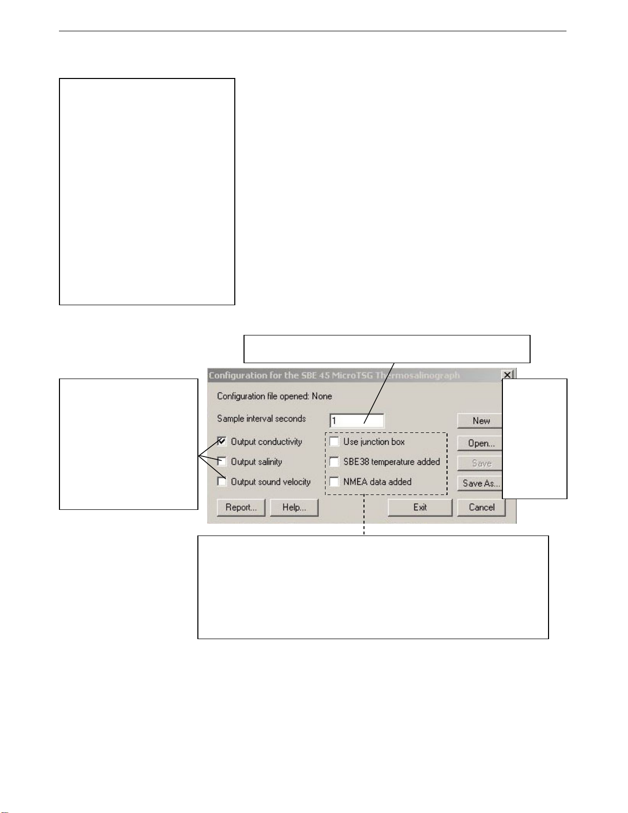
your system. Click Modify to bring up a dialog box (shown below) to
change the configuration.
Define data in MicroTSG data
stream:
• Output conductivity with each
scan - Must agree with MicroTSG
setup (OutputCond=).
• Output salinity with each scan –
Must agree with MicroTSG setup
(OutputSal=).
• Output sound velocity with each
scan – Must agree with MicroTSG
setup (OutputSV=).
See reply from DS for setup
programmed into MicroTSG.
Time between scans. Must agree with MicroTSG setup (Interval=); see reply
from DS.
New to create
new .xmlcon or
.con file for this
CTD.
Open to select
different .xmlcon
or .con file.
Save or Save
As to save
current .xmlcon
or .con file
settings.
• Use junction box – Select if MicroTSG data transmitted to computer through Interface Box.
• SBE 38 temperature added – only applicable if Use junction box is selected. Select if
Interface Box connected to SBE 38 remote temperature sensor. If selected, Seasave and
SBE Data Processing (Data Conversion and Derive modules) use remote temperature data
when calculating density and sound velocity.
• NMEA data added – only applicable if Use junction box is selected. Select if Interface Box
connected to a NMEA navigation device. Seasave automatically adds current latitude,
longitude, and universal time code to data header. Select NMEA (Lat/Lon) Interface in
Seasave’s Configure menu to control how Lat/Lon data is incorporated.
See PN 90402 – SBE 45 Power, Navigation, and Remote Temperatue Interface Box manual.
4. Click Save or Save As to save any changes to the .xmlcon or .con file.
Click Exit when done reviewing /modifying the configuration.
33
Page 42
Section 5: Operating System SBE 45
Section 5: Operating System
This section covers acquiring real-time data with Seasave, and processing data
Note:
For acquiring data in Seasave, the
MicroTSG must be set up for
autonomous sampling
(SingleSample=N).
Acquiring Real-Time Data with Seasave
Note:
See Seasave’s manual and/or
help files.
Note:
The baud rate between the
MicroTSG and computer (defined
in Configure Inputs, on the Serial
Ports tab) must agree with the
baud rate programmed into the
MicroTSG with Baud=.
with SBE Data Processing.
• Seasave saves the data in the format – data format and header information
– that is required by SBE Data Processing. If you use other software
to acquire data, the data will not be in the format required by
SBE Data Processing.
If using the MicroTSG with PN 90402 - SBE 45 Power, Navigation, and
Remote Temperature Interface Box, see the Interface Box manual for
operating the system.
1. Turn on power to the MicroTSG.
• If the MicroTSG is set to AutoRun=Y and the J1 jumper is in the
Autopower position (start sampling automatically when power is
turned on): MicroTSG will start sampling and transmitting data to the
computer. Note that the data will not appear in Seasave until you tell
Seasave to start real-time data acquisition in Step 7.
• If the MicroTSG is set to AutoRun=N or the J1 jumper is in the
Normal position: Run SEATERM, click SEATERM’s Connect
button, command the MicroTSG to start sampling (Go), click
SEATERM’s Disconnect button, and then close SEATERM.
See Section 4: Setting Up MicroTSG.
2. Double click on Seasave.exe.
3. Perform any desired setup in the Configure Inputs, Configure Outputs,
and Display menus.
39
34
Page 43
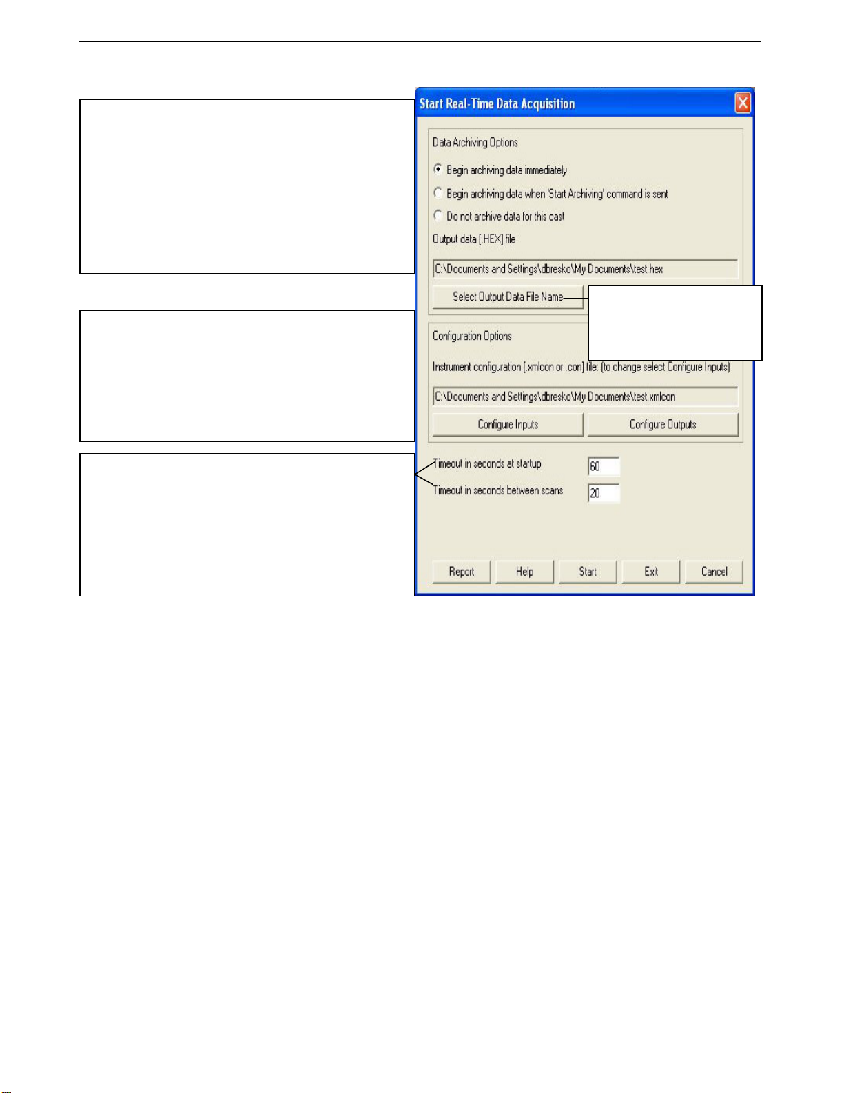
40
Section 5: Operating System SBE 45
4. In the RealTime Data menu, select Start Acquisition. The dialog box looks
like this:
Data Archiving Options:
• Begin archiving data immediately to store raw (frequencies,
A/D counts, and/or voltages) real-time data as soon as Start
button is clicked and communication is established.
• Begin archiving data when ‘Start Archiving’ command is
sent to control when data begins to be written to file. If you
make this selection, when you click Start button and
communication is established, a dialog box with Start Archiving
button appears. Click this button when ready to begin saving
scans to file, or select Start Archiving in Real-Time Data menu.
• Do not archive data for this cast to not save data to a file.
Real-time data will still appear in displays.
Click Select Output Data File
Configuration Options: Currently selected instrument
configuration (.xmlcon or .con) file is shown, containing information
on output from MicroTSG, use of Interface Box, and inclusion of
NMEA and SBE 38 data with output from MicroTSG. To modify
input configuration (xmlcon or .con file, serial ports, TCP/IP ports,
and/or miscellaneous), click Configure Inputs. To modify outputs
(serial data output, serial ports shared file output, mark variables,
TCP/IP output, TCP/IP ports, SBE 14 remote display, header form,
and/or diagnostics), click Configure Outputs.
Name. Save Archived Data As
dialog box appears; browse to
desired file location, enter desired
file name, and click Save.
• Timeout in seconds at startup: Time allowed before first data
scan is received from MicroTSG. Seasave will time out and stop
attempting to acquire data if data is not received from MicroTSG
within this time period.
• Timeout in seconds between scans: Maximum gap allowed
between scans after first data scan is received from MicroTSG.
Seasave will time out and stop attempting to acquire data if data
is not received from MicroTSG within this time period (for
example, if a problem with power interrupts data acquisition,
Seasave stops attempting to acquire data after this gap).
5. In the Start Real-Time Data Acquisition dialog box, click Start.
A. If you selected Begin archiving data immediately or Begin archiving
data when ‘Start Archiving’ command is sent above, and selected
Prompt for Header Information in the Header Form setup (Configure
Outputs), the Header Information dialog box appears. Fill in the
desired header and click OK.
B. If you selected Check Scan Length in the Options menu, Seasave
checks the configuration (.xmlcon or .con) file to verify that the scan
length defined by the configuration file matches the MicroTSG (i.e.,
number of sensors and inclusion of NMEA is as defined in the file). If a
Scan length error appears, verify that:
• You are using the correct .xmlcon or .con configuration file.
• The configuration file has been updated as necessary if you added
C. Seasave sends a message: Waiting for data . . . Seasave will time out
if data is not received within Timeout in seconds at startup.
D. Real-time data then starts appearing in the screen display(s).
6. To stop real-time data acquisition: In the Real-Time Data menu,
select Stop.
7. Stop the MicroTSG sampling by turning off power.
or deleted outputs, added or deleted Interface Box, etc.
35
Page 44
Section 5: Operating System SBE 45
Processing Data
Process the data in SBE Data Processing.
Note:
See the SBE Data Processing
manual and/or Help files.
Note:
Although we provide this
technique for editing a .hex file,
Sea-Bird’s strong
recommendation, as described
above, is to always convert the
.hex data file and then edit the
converted (.cnv) file.
1. Convert the .hex data file created by Seasave to a .cnv file in SBE Data
Processing’s Data Conversion module.
2. Once the data is converted, it can be further processed and plotted in
SBE Data Processing’s other modules.
Editing .hex Data File
Sometimes users want to edit the .hex data file before beginning processing, to
remove data at the beginning of the file corresponding to instrument soak time,
to remove blocks of bad data, to edit the header, or to add explanatory notes.
Editing the .hex file can corrupt the data, making it impossible to perform
further processing using Sea-Bird software. We strongly recommend that
you first convert the data to a .cnv file (using Data Conversion in SBE Data
Processing), and then use other SBE Data Processing modules to edit the
.cnv file as desired.
The procedure for editing a .hex data file described below has been found to
work correctly on computers running Windows 98, 2000, and NT. If the
editing is not performed using this technique, SBE Data Processing may
reject the edited data file and give you an error message.
1. Make a back-up copy of your .hex data file before you begin.
2. Run WordPad.
3. In the File menu, select Open. In the Open dialog box: for Files of type,
select All Documents (*.*). Browse to the desired .hex file and click Open.
4. Edit the file as desired, inserting any new header lines after the System
Upload Time line. Note that all header lines must begin with an asterisk
(*), and *END* indicates the end of the header. An example is shown
below (for an SBE 21 data file), with the added lines in bold:
* Sea-Bird SBE 21 Data File:
* FileName = C:\Odis\SAT2-ODIS\oct14-19\oc15_99.hex
* Software Version Seasave Win32 v1.10
* Temperature SN = 2366
* Conductivity SN = 2366
* System UpLoad Time = Oct 15 1999 10:57:19
* Testing adding header lines
* Must start with an asterisk
* Place anywhere between System Upload Time & END of header
* NMEA Latitude = 30 59.70 N
* NMEA Longitude = 081 37.93 W
* NMEA UTC (Time) = Oct 15 1999 10:57:19
* Store Lat/Lon Data = Append to Every Scan and Append to .NAV
File When <Ctrl F7> is Pressed
** Ship: Sea-Bird
** Cruise: Sea-Bird Header Test
** Station:
** Latitude:
** Longitude:
*END*
5. In the File menu, select Save (not Save As). If you are running
Windows 2000, the following message displays:
You are about to save the document in a Text-Only format,
which will remove all formatting. Are you sure you want to
do this?
Ignore the message and click Yes.
6. In the File menu, select Exit.
41
36
Page 45
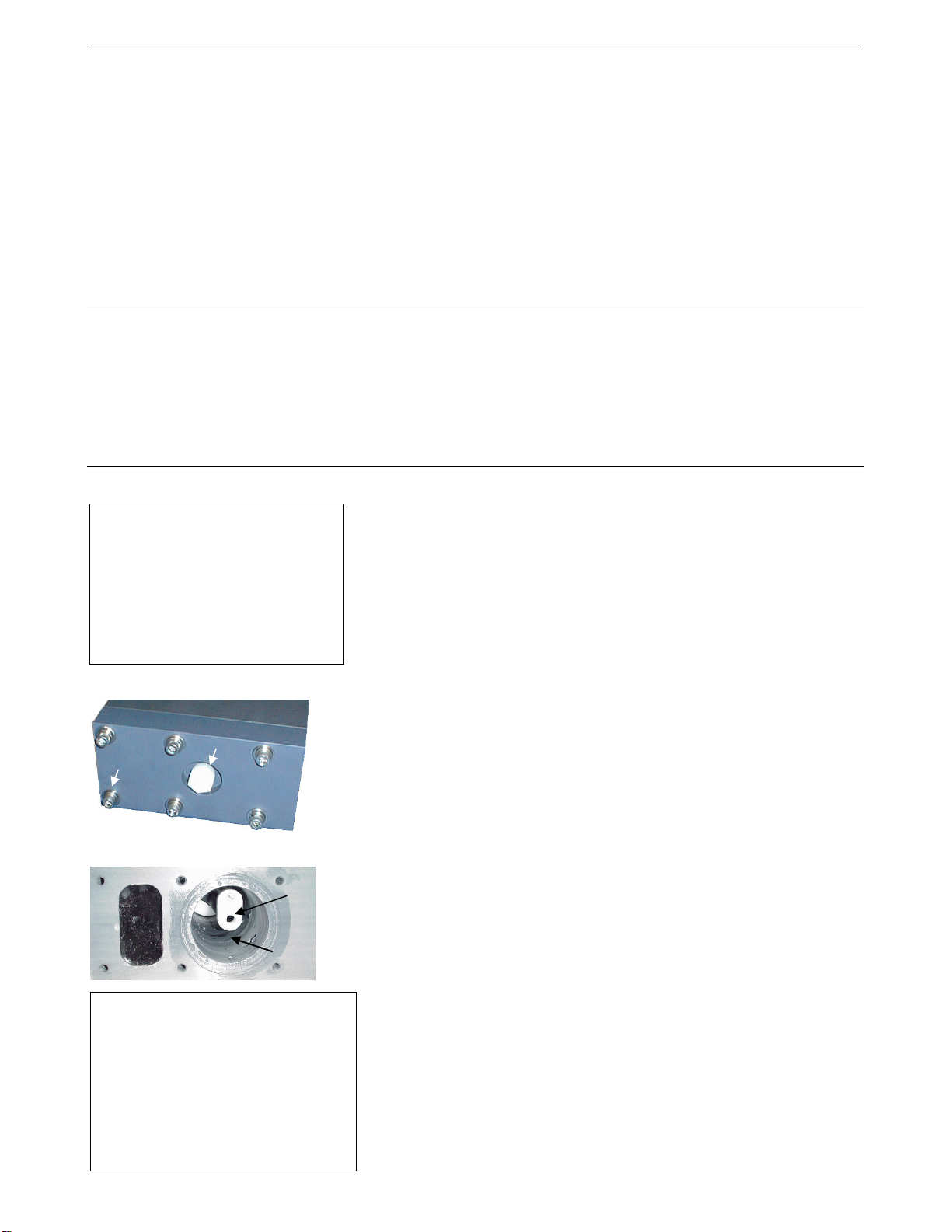
42
Section 6: Routine Maintenance and Calibration SBE 45
Section 6: Routine Maintenance and Calibration
This section reviews corrosion precautions, conductivity cell cleaning and
storage, replacement of the Anti-Foulant Device, and sensor calibration. The
accuracy of the MicroTSG is sustained by the care and calibration of the
sensors and by establishing proper handling practices.
Corrosion Precautions
All hardware exposed to seawater is titanium; the housing is plastic. No
corrosion precautions are required. The MicroTSG should be cleaned after use
and prior to storage, as described in Cleaning and Storage.
Cleaning and Storage
CAUTION:
The MicroTSG’s conductivity cell is
shipped dry to prevent freezing in
shipping.
MicroTSG with water in the
conductivity cell. Freezing
temperatures (for example, in Arctic
environments or during air shipment)
can break the cell if it is full of water.
CAUTION:
• Do not put a brush or any object
• Do not spray any solutions
If fouling remains in the conductivity
cell after these procedures, return the
MicroTSG to Sea-Bird for internal
cleaning and recalibration.
Do not store the
Drain
Screw
(typical)
inside the cell.
directly into the open end of
the cell.
plug
Bottom
plate
Plastic cap on
conductivity
cell
Flushing
chamber
Clean the MicroTSG and conductivity cell:
• Monthly (during sustained use)
• Before periods of non-use – If the cell is not rinsed between usage, salt
crystals may form on the platinized electrode surfaces. When the
instrument is used next, sensor accuracy may be temporarily affected until
these crystals dissolve.
• If the data looks incorrect –
¾ Unusually noisy data may be caused by debris going through the cell.
¾ Unusually smooth data may be caused by a blockage in the flow path
or in the cell.
¾ Shifted data may be caused by fouling inside the cell.
Follow this cleaning procedure:
Step 1: Clean Out Drain
A. Keeping the MicroTSG in an upright position, remove the drain plug from
the housing’s bottom plate.
B. Allow any water to drain out and remove any sediment or debris from
the drain.
Step 2: Inspect and Clean Flushing Chamber
A. Remove the bottom plate:
i. Remove the six
washers securing the plate to the housing body. Hold the bottom plate
as you remove the hardware, to prevent the plate from falling.
ii. Pull the bottom plate straight down from the housing body, being
careful not to damage the conductivity cell, which sits in the housing.
B. Use a flashlight to inspect the flushing chamber and conductivity cell for
debris or fine deposits. If this is a routine monthly maintenance, and there
is no evidence of debris or fine deposits, proceed to Step 4: Clean Bottom
Plate Assembly.
C. Gently spray fresh water up into the chamber to remove any fine deposits
inside the housing. Be careful not to hit the conductivity cell with the
spray hose.
1
/4-inch socket head screws, lock washers, and flat
37
Page 46
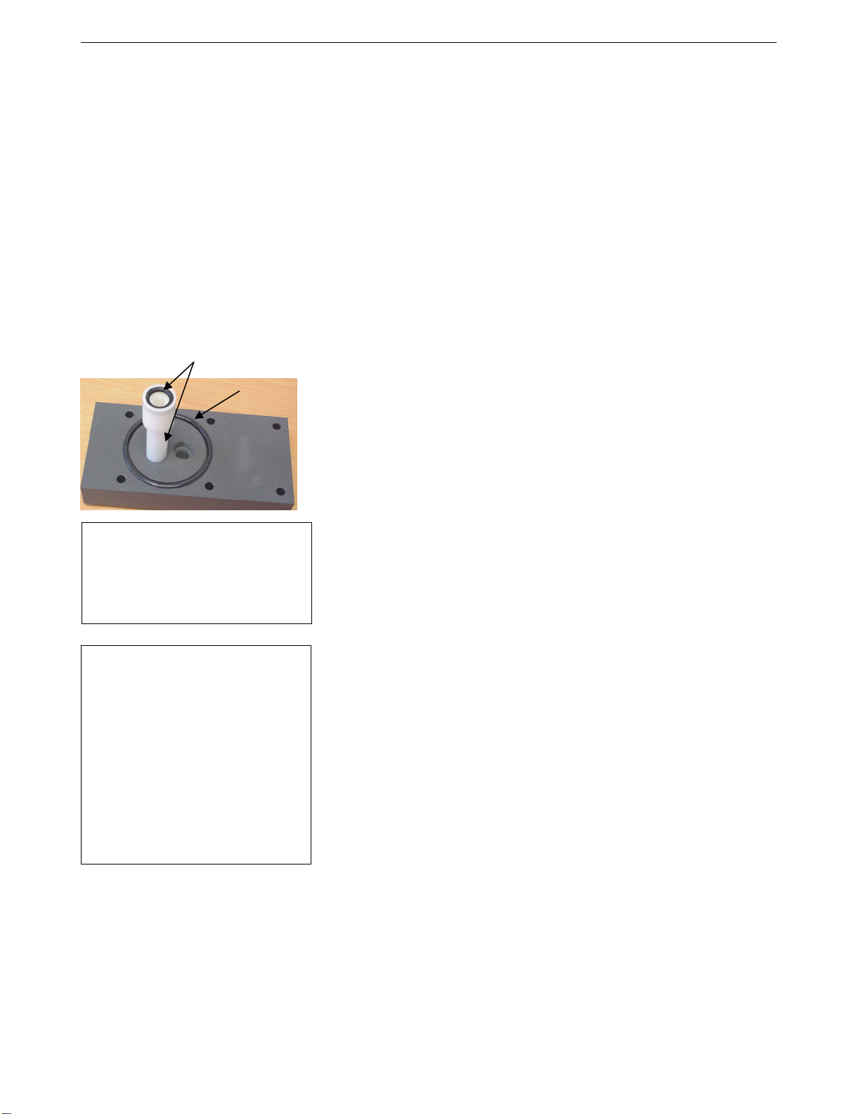
Section 6: Routine Maintenance and Calibration SBE 45
Step 3: Flush Inside of Conductivity Cell
A. Remove the external plumbing connecting the seawater intake and drain
lines to the MicroTSG.
B. Clean the inside of the conductivity cell with a series of slow back flushes
into the OUT port (reverse of the normal operation flow). Collect the
drainage in a bucket held below the open housing:
• Refer to Application Note 2D: Instructions for Care and Cleaning
of Conductivity Cells for conductivity cell cleaning materials and
concentrations.
• The Active Use (after each cast) section of the application note is not
applicable to the MicroTSG.
C. If the MicroTSG is being stored, gently blow-dry the conductivity cell
and flushing chamber. Do not use compressed air, which typically
contains oil vapor.
D. Reinstall the external plumbing connecting the seawater intake and drain
lines to the MicroTSG.
Flush through anti-foulant device cup
O-ring
Note:
Early versions of the SBE 45 had a
rectangular o-ring in addition to the
round o-ring on the bottom plate; see
the photo in Replacing Anti-Foulant
Device (SBE 45).
CAUTION:
• If you remove sensors and
electronics from the housing to
troubleshoot, avoid getting
anything on the PCB, which can
be damaged by water or other
materials. See Appendix II:
Electronics Disassembly/
Reassembly.
• Do not put any object inside the
conductivity cell to clean it.
Return the MicroTSG to Sea-Bird
for internal cleaning and
recalibration.
Step 4: Clean Bottom Plate Assembly
A. Remove the O-ring on the bottom plate. Put the O-ring aside, being
careful to protect it from damage or contamination.
B. Flush the anti-foulant device cup on the bottom plate with fresh water, to
remove any debris or fine deposits. See Replacing Anti-Foulant Device
for details on touching or handling the AF24173 Anti-Foulant Device.
C. Rinse the bottom plate with fresh water.
D. Remove water from the O-ring and the bottom plate with a lint-free cloth
or tissue.
E. Inspect the O-ring and mating surfaces for dirt, nicks, and cuts. Clean as
necessary. Apply a light coat of O-ring lubricant (Parker Super O Lube) to
the O-ring and mating surfaces.
F. Replace the O-ring on the bottom plate.
Step 5: Reinstall Bottom Plate
A. Align the bottom plate with the housing body, ensuring the end of the
anti-foulant device cup is aligned with the conductivity cell. Slowly
position the bottom plate on the housing.
B. Re-secure the bottom plate to the housing body with the six
socket head screws, lock washers, and flat washers.
C. Reinstall the drain plug in the bottom plate.
If the data still looks incorrect after cleaning, it may be caused by:
• a problem with the electrical connections
• a problem with the PCB
• internal fouling in the conductivity cell that was not removed by flushing
• sensors that need to be recalibrated
1
/4-inch
43
38
Page 47
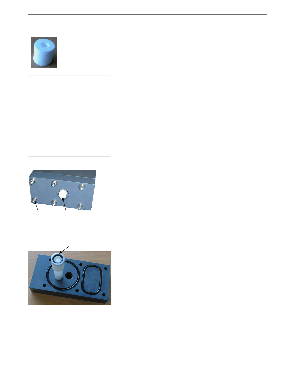
p
44
Section 6: Routine Maintenance and Calibration SBE 45
Replacing Anti-Foulant Device (SBE 45)
The MicroTSG has an anti-foulant device cup inside the housing. New
MicroTSGs are shipped with an Anti-Foulant Device pre-installed in the cup.
AF24173
Anti-Foulant
Device
WARNING!
AF24173 Anti-Foulant Devices
contain bis(tributyltin) oxide. Handle
the devices only with rubber or latex
gloves. Wear eye protection. Wash
with soap and water after handling.
Read precautionary information on
product label (see Appendix IV)
before proceeding.
It is a violation of US Federal Law to
use this product in a manner
inconsistent with its labeling.
Screw
(typical)
Drain
plug
O-ring, Anti-Foulant
Device, and cu
Anti-Foulant Devices are sold packaged in pairs. The second device should be
retained as a spare; reseal in its original plastic bag and store in a cool location.
Wearing rubber or latex gloves, follow this procedure:
1. Keeping the MicroTSG in an upright position, remove the drain plug from
the housing’s bottom plate. Allow any water to drain out and remove any
sediment or debris from the drain before proceeding.
2. Remove the bottom plate:
1
A. Remove the six
/4-inch socket head screws, lock washers, and flat
washers securing the bottom plate to the housing body. Hold the
bottom plate as you remove the hardware, to prevent it from falling.
B. Pull the bottom plate straight down from the housing body, being
careful not to damage the conductivity cell, which sits in the housing
at the end of the anti-foulant device cup.
3. Remove the Anti-Foulant Device:
A. Place the bottom plate on a horizontal surface. Remove the small
O-ring securing the Anti-Foulant Device in the anti-foulant
device cup.
B. Remove the old Anti-Foulant Device. If it is difficult to remove, use
needle-nose pliers and carefully break up the material.
4. Clean the bottom plate assembly:
A. Remove the two O-rings on the bottom plate. Put the O-rings aside,
being careful to protect them from damage or contamination.
B. Rinse the bottom plate and flush the inside of the anti-foulant device
cup and post with fresh water to remove sediment or debris.
C. Remove water from the O-rings and the bottom plate with a lint-free
cloth or tissue.
D. Inspect the O-rings and mating surfaces for dirt, nicks, and cuts.
Clean as necessary. Apply a light coat of O-ring lubricant (Parker
Super O Lube) to the O-rings and mating surfaces.
E. Replace the O-rings on the bottom plate.
5. Place the new Anti-Foulant Device in the cup, and replace the O-ring.
6. Reinstall the bottom plate:
A. Align the bottom plate with the housing body, ensuring the end of the
Anti-Foulant Device cup is aligned with the conductivity cell. Slowly
position the bottom plate on the housing.
1
B. Re-secure the bottom plate to the housing body with the six
/4-inch
socket head screws, lock washers, and flat washers.
C. Reinstall the drain plug in the bottom plate.
39
Page 48

Section 6: Routine Maintenance and Calibration SBE 45
Sensor Calibration
Sea-Bird sensors are calibrated by subjecting them to known physical
conditions and measuring the sensor responses. Coefficients are then
computed which may be used with appropriate algorithms to obtain
engineering units. The conductivity and temperature sensors on the MicroTSG
are supplied fully calibrated, with coefficients printed on their respective
Calibration Certificates (see back of manual). These coefficients have been
stored in the MicroTSG’s EEPROM.
Note:
Do not disassemble the MicroTSG
to send the sensors to Sea-Bird for
recalibration. Package the entire
MicroTSG for shipment, after
removing the AF24173 Anti-Foulant
Device (see Replacing Anti-Foulant
Device). Store the AF24173 AntiFoulant Device for future use.
We recommend that MicroTSGs be returned to Sea-Bird for calibration.
Conductivity Sensor Calibration
The conductivity sensor incorporates a fixed precision resistor in parallel with
the cell. When the cell is dry and in air, the sensor’s electrical circuitry outputs
a frequency representative of the fixed resistor. This frequency is recorded on
the Calibration Certificate and should remain stable (within 1 Hz) over time.
The primary mechanism for calibration drift in conductivity sensors is the
fouling of the cell by chemical or biological deposits. Fouling changes the cell
geometry, resulting in a shift in cell constant.
Accordingly, the most important determinant of long-term sensor accuracy is
the cleanliness of the cell. We recommend that the conductivity sensors be
calibrated before and after deployment, but particularly when the cell has been
exposed to contamination by oil slicks or biological material.
Temperature Sensor Calibration
The primary source of temperature sensor calibration drift is the aging of the
thermistor element. Sensor drift will usually be a few thousandths of a degree
during the first year, and less in subsequent intervals. Sensor drift is not
substantially dependent upon the environmental conditions of use, and —
unlike platinum or copper elements — the thermistor is insensitive to shock.
45
40
Page 49

46
Section 7: Troubleshooting SBE 45
Section 7: Troubleshooting
Note:
See the PN 90402 – SBE 45 Power,
Navigation, and Remote Temperature
Interface Box manual for additional
troubleshooting steps when
interfacing with the Box.
This section reviews common problems in operating the MicroTSG, and
provides the most common causes and solutions.
Problem 1: Unable to Communicate with MicroTSG
The S> prompt indicates that communications between the MicroTSG and
computer have been established. Before proceeding with troubleshooting,
attempt to establish communications again by clicking Connect on
SEATERM’s toolbar or hitting the Enter key several times.
Cause/Solution 1: The I/O cable connection may be loose. Check the cabling
between the MicroTSG and computer (or optional Interface Box) for a
loose connection.
Cause/Solution 2: The instrument type and/or its communication settings may
not have been entered correctly in SEATERM. Select the SBE 45 in the
Configure menu and verify the settings in the Configuration Options dialog
box. The settings should match those on the instrument Configuration Sheet.
Cause/Solution 3: The I/O cable may not be the correct one. Verify the cable
is the correct one.
Problem 2: Nonsense or Unreasonable Data
The symptom of this problem is data that contains nonsense values (for
example, 9999.999) or unreasonable values (for example, values that are
outside the expected range of the data).
Cause/Solution 1: A data file with nonsense values may be caused by
incorrect instrument configuration in the .xmlcon or .con file. Verify the
settings in the configuration file match your system.
Cause/Solution 2: Unreasonable values may be caused by incorrect calibration
coefficients programmed into the MicroTSG. Verify the coefficients match the
instrument Calibration Certificates, using DC.
Problem 3: Salinity Lower than Expected
Cause/Solution 1: A fouled conductivity cell will report lower than correct
salinity. Large errors in salinity indicate that the cell is extremely dirty, has
something large lodged in it, or is broken. Proceed as follows:
1. Clean the conductivity cell as described in Cleaning and Storage in
Section 6: Routine Maintenance and Calibration.
2. Remove larger droplets of water by blowing through the conductivity cell.
Do not use compressed air, which typically contains oil vapor.
3. Running the MicroTSG in air, use TSR to look at the raw conductivity
frequency. It should be within 1 Hz of the zero conductivity value printed
on the conductivity cell Calibration Sheet. If it is significantly different,
the cell is probably damaged.
41
Page 50

Glossary SBE 45
Glossary
Fouling – Biological growth in the conductivity cell during deployment.
PN 90402 - SBE 45 Power, Navigation, and Remote Temperature
Interface Box – Optional Box provides:
• Power and an opto-isolated RS-232C interface for the MicroTSG
• An opto-isolated NMEA receiver for a NMEA navigation device
(NMEA navigation device not supplied by Sea-Bird)
• Power and an RS-232C interface for an SBE 38 remote
temperature sensor
• An RS-232 computer interface
PCB – Printed Circuit Board.
Scan – One data sample containing temperature and conductivity, as well as
derived variables (salinity and sound velocity).
SBE 45 MicroTSG – High-accuracy conductivity and temperature monitor.
SBE Data Processing – Sea-Bird’s Win 2000/XP data processing
software, which calculates temperature and conductivity,
as well as data from auxiliary sensors, and derives variables such as
salinity and sound velocity.
Seasave V7 – Sea-Bird’s Windows 2000/XP software used to acquire,
convert, and display real-time or archived raw data.
SEASOFT V2– Sea-Bird’s complete Windows 2000/XP software package,
which includes software for communication, real-time data acquisition, and
data analysis and display. SEASOFT V2 includes SEATERM, Seasave V7,
SBE Data Processing.
SEATERM – Sea-Bird’s Win 95/98/NT/2000/XP terminal program used to
communicate with the MicroTSG. SEATERM can send commands to the
MicroTSG to provide status display, data acquisition setup, data display and
capture, and diagnostic tests.
Super O-Lube – Silicone lubricant used to lubricate O-rings and O-ring
mating surfaces. Super O-Lube can be ordered from Sea-Bird, but should also
be available locally from distributors. Super O-Lube is manufactured by
Parker Hannifin (www.parker.com/ead/cm2.asp?cmid=3956).
TCXO – Temperature Compensated Crystal Oscillator.
Triton X-100 – Reagent grade non-ionic surfactant (detergent), used for
cleaning the conductivity cell. Triton can be ordered from Sea-Bird, but should
also be available locally from chemical supply or laboratory products
companies. Triton is manufactured by Mallinckrodt Baker (see
www.mallbaker.com/changecountry.asp?back=/Default.asp for local
distributors).
47
42
Page 51

48
Appendix I: Functional Description SBE 45
Appendix I: Functional Description
Sensors
The MicroTSG embodies the same sensor elements (3-electrode, 2-terminal,
borosilicate glass cell, and pressure-protected thermistor) previously employed
in Sea-Bird’s modular SBE 3 and SBE 4 sensors, in the SEACAT and
SEACAT plus family, and in the SBE 37 MicroCAT family.
Sensor Interface
Temperature is acquired by applying an AC excitation to a hermetically-sealed
VISHAY reference resistor and an ultra-stable aged thermistor with a drift rate
of less than 0.002 °C per year. A 24-bit A/D converter digitizes the outputs of
the reference resistor and thermistor. AC excitation and ratiometric
comparison using a common processing channel avoids errors caused by
parasitic thermocouples, offset voltages, leakage currents, and reference errors.
Conductivity is acquired using an ultra-precision Wein Bridge oscillator to
generate a frequency output in response to changes in conductivity. A high
stability TCXO reference crystal with a drift rate of less than 2 ppm/year is
used to count the frequency from the Wein Bridge oscillator.
43
Page 52
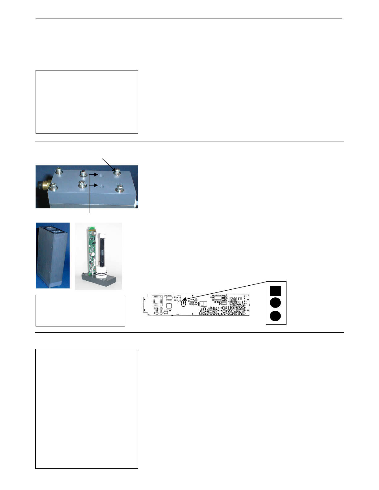
Appendix II: Electronics Disassembly/Reassembly SBE 45
)
Appendix II: Electronics Disassembly/Reassembly
Note:
Do not disassemble the MicroTSG
to send the sensors or PCB to
Sea-Bird for recalibration or repair.
Package the entire MicroTSG for
shipment, after removing the
AF24173 Anti-Foulant Device
(see Section 6: Routine Maintenance
and Calibration).
Disassembly
Screw (typical, 6 places)
Do not remove
CAUTION:
Avoid getting anything on the
PCB, which can be damaged by
water or other materials.
Do not disassemble the MicroTSG electronics unless:
• moving the J1 jumper on the PCB to change operation from Autopower
(default) to Normal, or vice versa, or
• troubleshooting a problem, requiring access to the PCB or sensors
1
1. Remove the six
/4-inch socket head screws, lock washers, and flat
washers securing the top plate to the housing body. Do not remove the
two screws that are recessed in the top plate – these secure the
electronics to the top plate.
2. Remove the top plate by pulling up on it firmly and steadily. It may be
necessary to slightly twist the top plate back and forth to loosen the o-ring
seals. Lift the top plate vertically off the housing body, being careful not
to hit the conductivity cell on the housing body.
3. Remove any water from the O-ring mating surfaces on the top plate
assembly and on the housing with a lint-free cloth or tissue.
4. If applicable, verify/change J1 jumper setting.
PCB (labeled 10235
1
2
3
J1
Pin position on J1:
• Autopower (default) –
pins 1 and 2
• Normal –
pins 2 and 3
49
Reassembly
Note:
Before delivery, a desiccant package
is placed in the electronic chamber,
and the chamber is filled with dry
Argon gas. These measures help
prevent condensation. To ensure
proper functioning:
1. Install a new desiccant bag each
time you open the housing. If a
new bag is not available, see
Application Note 71: Desiccant
Use and Regeneration (drying).
2. If possible, dry gas backfill each
time you open the housing. If you
cannot, wait at least 24 hours
before redeploying, to allow the
desiccant to remove any moisture.
1. Remove any water from the O-rings and mating surfaces with a lint-free
cloth or tissue. Inspect the O-rings and mating surfaces for dirt, nicks, and
cuts. Clean as necessary. Apply a light coat of O-ring lubricant (Parker
Super O Lube) to O-rings and mating surfaces.
2. Align the top plate with the housing body, with the conductivity cell’s
round end cap aligned with the round opening in the housing body.
Slowly lower the top plate, checking that it remains aligned with the
housing body. You will feel resistance as the O-rings on the sensor end
cap enter the housing.
1
3. Re-secure the top plate to the housing body with the six
/4-inch socket
head screws, lock washers, and flat washers.
44
Page 53
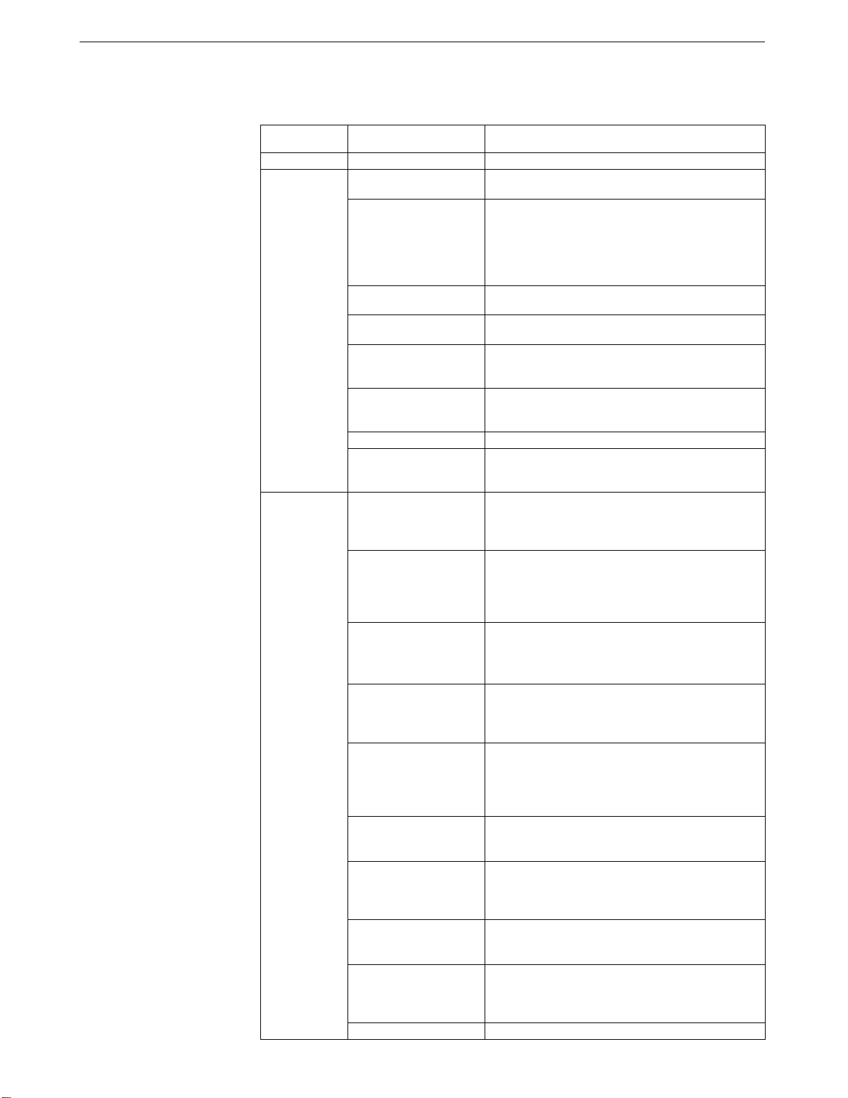
50
Appendix III: Command Summary SBE 45
Appendix III: Command Summary
CATEGORY COMMAND DESCRIPTION
Status DS
Baud=x
OutputFormat=x
OutputCond=x
Setup
OutputSal=x
OutputSV=x
SVAlgorithm=x
NCycles=x
QS
Interval=x
AutoOff=x
J1 jumper - Normal
AutoRun=N
SingleSample=
Y or N
Operating
PCB’s J1
jumper interacts
with these
commands:
• Autopower –
pins 1 and 2
• Normal –
pins 2 and 3
J1 jumper - Normal
AutoRun=Y
SingleSample=N
J1 jumper - Normal
AutoRun=Y
SingleSample=Y
J1 jumper - Autopower
AutoRun=N
SingleSample=Y or N
J1 jumper - Autopower
AutoRun=Y
SingleSample=N
J1 jumper - Autopower
AutoRun=Y
SingleSample=Y
Go
Stop
Display status.
x= baud rate (1200, 2400, 4800, 9600, 19200,
or 38400). Default 4800.
x=0 (default): Output order is temperature,
conductivity, salinity, sound velocity.
x=1: Suppress space before conductivity output.
x=2: Reverse conductivity and salinity order (not for
use with Seasave, SBE Data Processing, or optional
Interface Box).
x=Y (default): Output conductivity (S/m) with data.
x=N: Do not.
x=Y: Output salinity (psu) with data.
x=N (default): Do not.
x=Y: Output sound velocity (m/sec) with data,
calculated as defined by SVAlgorithm=.
x=N (default): Do not.
x=C (default): Calculate sound velocity as Chen
and Millero.
x=W: Calculate sound velocity as Wilson.
x = A/D cycles to average per sample (default=4).
Quit session and place MicroTSG in quiescent (sleep)
state. Sampling stops. Applicable only if PCB J1
jumper in Normal position.
x= interval (seconds) between samples (maximum
32767). Minimum time between samples determined
by NCycles=, desired parameters (salinity, etc.), and
baud rate.
(Functional only if J1 jumper in Normal position)
x=Y: Go to sleep (enter quiescent state) if 2 minutes
have elapsed without receiving a command or without
sampling data.
x=N: Do not automatically go to sleep.
Wake up when Connect on Toolbar clicked or Enter
key pressed while in quiescent (sleep) state, wait for a
command.
Wake up when Connect on Toolbar clicked or Enter
key pressed while in quiescent (sleep) state, sample at
rate specified by Interval=. To stop sampling and get
S> prompt, type Stop and press Enter key.
Wake up when Connect on Toolbar clicked or Enter
key pressed while in quiescent (sleep) state, take and
output a single sample, automatically go to sleep. To
wake up and get S> prompt, type Stop and press
Enter key.
Wake up when power applied, wait for a command.
Wake up when power applied, sample at rate specified
by Interval= until power removed. Required settings
for running MicroTSG in 3-wire (power, ground,
transmit) configuration or with Interface Box.
Wake up when power applied, take and output a
single sample. Wait for another command until
power removed.
Start sampling, as defined by SingleSample=
and Interval=. Applicable if AutoRun=N, or
AutoRun=Y and you previously sent Stop to
stop sampling.
Stop sampling.
45
Page 54

Appendix III: Command Summary SBE 45
CATEGORY COMMAND DESCRIPTION
Polled
Sampling
Do not send these
commands if
MicroTSG is
sampling data at
pre-programmed
intervals.
Testing
Coefficients
(F=floating
point number;
S=string with
no spaces)
Dates shown
are when
calibrations
were
performed.
Calibration
coefficients are
initially factory-
set and should
agree with
Calibration
Certificates
shipped with
MicroTSGs.
TS
TSR
SLT
TH
SH
TT
TC
TTR
TCR
DC
TCalDate=S
TA0=F
TA1=F
TA2=F
TA3=F
CCalDate=S
CG=F
CH=F
CI=F
CJ=F
WBOTC=F
CTCor=F
CPCor=F
Take sample, hold converted data in RAM, output
converted data
Take sample, hold raw data in RAM, output raw data.
Send converted data from last sample in RAM, then
take new sample and hold converted data in RAM.
Take sample, hold converted data in RAM.
Send held converted data from RAM.
Measure temperature 100 times or until Esc key is
pressed, output converted data.
Measure conductivity 100 times or until Esc key is
pressed, output converted data.
Measure temperature 100 times or until Esc key is
pressed, output raw data
Measure conductivity 100 times or until Esc key is
pressed, output raw data.
Display calibration coefficients; all coefficients and
dates listed below are included in display. Use
individual commands below to modify a particular
coefficient or date.
S=Temperature calibration date.
F=Temperature A0.
F=Temperature A1.
F=Temperature A2.
F=Temperature A3.
S=Conductivity calibration date.
F=Conductivity G.
F=Conductivity H.
F=Conductivity I.
F=Conductivity J.
F=Conductivity wbotc.
F=Conductivity ctcor.
F=Conductivity cpcor.
51
46
Page 55
52
Appendix IV: AF24173 Anti-Foulant Device SBE 45
Appendix IV: AF24173 Anti-Foulant Device
AF24173 Anti-Foulant Devices supplied for user replacement are supplied in
polyethylene bags displaying the following label:
FOR USE ONLY IN SEA-BIRD ELECTRONICS' CONDUCTIVITY SENSORS TO CONTROL THE GROWTH OF AQUATIC ORGANISMS
WITHIN ELECTRONIC CONDUCTIVITY SENSORS.
ACTIVE INGREDIENT:
Bis(tributyltin) oxide…………..…………………………..... 53.0%
OTHER INGREDIENTS: ………………………………..... 47.0%
Total………………………………………………………..... 100.0%
DANGER
See the complete label within the Conductivity Instrument Manual for Additional Precautionary Statements and Information on the Handling, Storage, and
Disposal of this Product.
Net Contents: Two anti-foulant devices
Sea-Bird Electronics, Inc. EPA Registration No. 74489-1
13431 NE 20
Bellevue, WA 98005
th
Street EPA Establishment No. 74489-WA-1
AF24173 ANTI-FOULANT DEVICE
47
Page 56
Appendix IV: AF24173 Anti-Foulant Device SBE 45
AF24173 Anti-Foulant Device
FOR USE ONLY IN SEA-BIRD ELECTRONICS’ CONDUCTIVITY SENSORS TO CONTROL
THE GROWTH OF AQUATIC ORGANISMS WITHIN ELECTRONIC CONDUCTIVITY
SENSORS.
ACTIVE INGREDIENT:
Bis(tributyltin) oxide…………..…………………………..... 53.0%
OTHER INGREDIENTS: ………………………………..... 47.0%
Total………………………………………………………..... 100.0%
DANGER
See Precautionary Statements for additional information.
FIRST AID
If on skin or
clothing
• Take off contaminated clothing.
• Rinse skin immediately with plenty of water for15-20 minutes.
• Call a poison control center or doctor for treatment advice.
If swallowed
• Call poison control center or doctor immediately for treatment advice.
• Have person drink several glasses of water.
• Do not induce vomiting.
• Do not give anything by mouth to an unconscious person.
If in eyes
• Hold eye open and rinse slowly and gently with water for 15-20
minutes.
• Remove contact lenses, if present, after the first 5 minutes, then continue
rinsing eye.
• Call a poison control center or doctor for treatment advice.
HOT LINE NUMBER
Note to Physician Probable mucosal damage may contraindicate the use of gastric lavage.
Have the product container or label with you when calling a poison control center or doctor, or
going for treatment. For further information call National Pesticide Telecommunications
Network (NPTN) at 1-800-858-7378.
Net Contents: Two anti-foulant devices
Sea-Bird Electronics, Inc. EPA Registration No. 74489-1
13431 NE 20
Bellevue, WA 98005
th
Street EPA Establishment No. 74489-WA-1
53
48
Page 57

54
Appendix IV: AF24173 Anti-Foulant Device SBE 45
PRECAUTIONARY STATEMENTS
HAZARD TO HUMANS AND DOMESTIC ANIMALS
DANGER
Corrosive - Causes irreversible eye damage and skin burns. Harmful if swallowed. Harmful if
absorbed through the skin or inhaled. Prolonged or frequently repeated contact may cause allergic
reactions in some individuals. Wash thoroughly with soap and water after handling.
PERSONAL PROTECTIVE EQUIPMENT
USER SAFETY RECOMMENDATIONS
Users should:
• Remove clothing immediately if pesticide gets inside. Then wash thoroughly and put on
clean clothing.
• Wear protective gloves (rubber or latex), goggles or other eye protection, and clothing to
minimize contact.
• Follow manufacturer’s instructions for cleaning and maintaining PPE. If no such instructions
for washables, use detergent and hot water. Keep and wash PPE separately from other
laundry.
• Wash hands with soap and water before eating, drinking, chewing gum, using tobacco or
using the toilet.
ENVIRONMENTAL HAZARDS
Do not discharge effluent containing this product into lakes, streams, ponds, estuaries, oceans, or other
waters unless in accordance with the requirements of a National Pollutant Discharge Elimination
System (NPDES) permit and the permitting authority has been notified in writing prior to discharge.
Do not discharge effluent containing this product to sewer systems without previously notifying the
local sewage treatment plant authority. For guidance contact your State Water Board or Regional
Office of EPA. This material is toxic to fish. Do not contaminate water when cleaning equipment or
disposing of equipment washwaters.
PHYSICAL OR CHEMICAL HAZARDS
Do not use or store near heat or open flame. Avoid contact with acids and oxidizers.
DIRECTIONS FOR USE
It is a violation of Federal Law to use this product in a manner inconsistent with its labeling. For use
only in Sea-Bird Electronics’ conductivity sensors. Read installation instructions in the applicable
Conductivity Instrument Manual.
49
Page 58
Appendix IV: AF24173 Anti-Foulant Device SBE 45
STORAGE AND DISPOSAL
PESTICIDE STORAGE: Store in original container in a cool, dry place. Prevent exposure to
heat or flame. Do not store near acids or oxidizers. Keep container tightly closed.
PESTICIDE SPILL PROCEDURE: In case of a spill, absorb spills with absorbent material. Put
saturated absorbent material to a labeled container for treatment or disposal.
PESTICIDE DISPOSAL: Pesticide that cannot be used according to label instructions must be
disposed of according to Federal or approved State procedures under Subtitle C of the Resource
Conservation and Recovery Act.
CONTAINER HANDLING: Nonrefillable container. Do not reuse this container for any other
purpose. Offer for recycling, if available.
Sea-Bird Electronics/label revised 01-28-10
55
50
Page 59
y
56
Appendix V: Replacement Parts SBE 45
Appendix V: Replacement Parts
Part
Number
3/8" NPT to Hose Barb
30541
801542.1
30411 Triton X-100
801392
171888
60036
30507
31058
30818
Fitting for 3/8" Tygon
tubing, Parker, N6MCB6
AF24173 Anti-Foulant
Device
4-pin MCIL-4MP to
9-pin DB-9S I/O cable
with power leads,
2.4 m (8 ft) long
25-pin DB-25S to 9-pin
DB-9P cable adapter
Spare hardware/
O-ring kit
O-ring,
Parker 2-206N674-70
O-ring,
Parker 2-239N674-70
O-ring,
Parker 2-203N674-70
Part Application Description
Intake and exhaust nozzles on
water jacket
Bis(tributyltin) oxide device
inserted into anti-foulant
device cup
Octyl Phenol Ethoxylate –
Reagent grade non-ionic
cleaning solution for
conductivity cell (supplied in
100% strength; dilute as
directed)
From MicroTSG to computer 1
For use with computer with
DB-25 connector
Assorted hardware and
O-rings, including:
• 31132 Cap screw, 1/4-20 x
13/4”, 316 stainless steel
(secures top and bottom plates
to housing body)
• 30254 Washer, 1/4” split ring
lock, stainless steel
(for screw 31132)
• 30570 Washer, 1/4” flat,
stainless steel
(for screw 31132)
• 31057 O-ring, Parker
2-229N674-70
(round seal between bottom
plate and housing)
• 31062 Plug N6HPL, 3/8 NPT
Nylon (drain plug for
bottom plate)
Seal for conductivity cell end,
secures AF24173 Anti-Foulant
Device in anti-foulant
device cup
Large seal for top plate to
housing body
Seal for top plate to housing
body center screws
Quantit
MicroTSG
2
1
1
1
-
1
1
2
in
51
Page 60

Index SBE 45
Index
57
.
.con file · 33
.xmlcon file · 33
A
Anti-Foulant Device · 47
removal before shipping to Sea-Bird · 40
replacing · 39
B
Baud rate · 12
Bubbles · 16
C
Cable length · 12, 13
Calibration · 40
Cleaning · 37
Command summary · 45
Commands
autonomous sampling · 29
averaging · 28
baud · 28
calibration coefficients · 31
descriptions · 27
format · 28
operating · 29
polled sampling · 30
sampling · 29
setup · 28
sleep · 28
status · 27
testing · 30
Communication defaults · 22
Configuration file · 33
Connector · 10
Corrosion precautions · 37
D
Data acquisition · 34
Data output format · 32
Data processing · 36
Data transmission rate · 12
Description · 7
Dimensions · 10
E
Electronics disassembly/reassembly · 44
F
Format
data output · 32
Functional description · 43
G
Glossary · 42
I
Installation
remote temperature sensor · 14
system · 19
Installation guidelines · 16
Interface Box · 16
J
Jumper
power-up · 18, 23, 44
M
Maintenance · 37
Modes · See Sampling modes
Mounting · 16
O
Operating system · 34
P
Parker Super O-Lube · 42
Parts
replacement · 51
Power · 13
Processing data · 36
Pump · 16
Q
Quick start · 5
R
Real-time acquisition · 34
Remote temperature sensor · 14, 16
Replacement parts · 51
52
Page 61

58
Index SBE 45
S
Sample timing · 11
Sampling modes · 24
SBE 38 remote temperature sensor · 14, 16
SBE Data Processing · 8, 15, 33, 36
Schematic · 16
Seasave · 8, 15, 33, 34
SEASOFT · 8, 15
SEATERM · 8, 15, 20
Setup · 20
Software · 8, 15
Specifications · 9
Storage · 37
Super O-Lube · 42
System
operation · 34
schematic · 16
System description · 7
T
Terminal program · 8
Testing · 20
Timeout description · 26
Triton · 42
Troubleshooting · 37, 41
U
Unpacking MicroTSG · 6
53
Page 62

SBE 45 MicroTSG (RS-232) Reference Sheet
(see SBE 45 MicroTSG User’s Manual for complete details)
Deployment
1. Verify setting of Power-Up Jumper J1 (see product configuration sheet on manual front cover for factory-setting):
• Autopower (default) – pins 1 and 2. The MicroTSG wakes up when power is applied.
• Normal – pins 2 and 3. The MicroTSG power up (wakes up) when there is a pulse on the serial lines. In this configuration,
the MicroTSG can be commanded into a quiescent (sleep) state with the QS command.
If the factory-setting listed on the product configuration sheet does not match your desired operation, see the manual for
procedures for accessing the PCB.
2. Mount MicroTSG on ship, with electrical connector at top, using four
• Bottom — 152 mm (6 inches) clearance for removal of the bottom plate, to allow access for replacing the anti-foul cylinder
and cleaning.
• Top — 305 mm (12 inches) clearance for removal of the top plate, to allow access for removing sensors and electronics.
• Sides — small clearance by using washers with the mounting hardware, to prevent binding when removing the top or
bottom plate.
3. Install piping connections to MicroTSG’s
4. Wiring to MicroTSG:
A. Install I/O cable connector, aligning long pin with small hole on MicroTSG I/O connector.
B. Tighten locking sleeve on I/O cable connector.
C. Connect I/O cable connector to computer serial port.
D. Connect I/O cable connector’s red and black wires to power supply (8-30 VDC).
3
/8-inch U.S. Standard NPT threads.
1
/4-inch bolt holes on sides. Provide clearance as follows:
59
Communication Setup Parameters
1. Double click on the SEATERM icon.
2. Once the main screen appears, in the Configure menu select the SBE 45 TSG. Input:
• Serial Port: COM1 through COM10 are available
• Baud Rate: 4800 (or other if applicable)
• Data Bits: 8
• Parity: No Parity
• Mode: RS-232 (full duplex)
Sampling Modes
User-selectable modes include:
• Polled sampling – The MicroTSG takes one sample and sends the data to the computer. Polled sampling is useful for testing.
• Autonomous sampling – The MicroTSG samples data at pre-programmed intervals, defined by the Interval= command, and
sends the data to the computer. The MicroTSG does not enter quiescent (sleep) state between samples.
• Serial Line Sync - A pulse on the serial line causes the MicroTSG to wake up, take and output a single sample, and enter
quiescent (sleep) state automatically.
Reference Sheet Version #007, 06-11-08; Firmware Version 1.1b
1
Page 63

60
Command Instructions and List
• Input commands in upper or lower case letters and register commands by pressing the Enter key.
• If in quiescent (sleep) state, re-establish communications by pressing Connect on the Toolbar or the Enter key to get S> prompt.
• If system does not return S> prompt after executing a command, press Enter key to get S> prompt.
• MicroTSG sends ?CMD if invalid command is entered.
Shown below are the commands used most commonly in the field. See the Manual for a complete list and detailed descriptions.
CATEGORY COMMAND DESCRIPTION
Status
Setup
Operating Mode
Interface PCB’s J1
jumper interacts with
these commands:
• Autopower
(default) –
pins 1 and 2
• Normal –
pins 2 and 3
Sampling
Do not send if
MicroTSG is
sampling data at
pre-programmed
intervals.
Testing
Coefficients
SingleSample=Y or N
J1 jumper - Autopower
SingleSample=Y or N
J1 jumper - Autopower
J1 jumper - Autopower
DS
Baud=x
OutputFormat=x
OutputCond=x
OutputSal=x
OutputSV=x
SVAlgorithm=x
NCycles=x
QS
Interval=x
AutoOff=x
J1 jumper - Normal
AutoRun=N
J1 jumper - Normal
AutoRun=Y
SingleSample=N
J1 jumper - Normal
AutoRun=Y
SingleSample=Y
AutoRun=N
AutoRun=Y
SingleSample=N
AutoRun=Y
SingleSample=Y
Go
Stop
TS
TSR
SLT
TH
SH
TT
TC
TTR
TCR
DC
Reference Sheet Version #007, 06-11-08; Firmware Version 1.1b
Display status.
x= baud rate (1200, 2400, 4800, 9600, 19200, 38400). Default 4800.
x=0 (default): Output order is temperature, conductivity, salinity, sound velocity.
x=1: Suppress space before conductivity output.
x=2: Reverse conductivity and salinity order (not for use with SEASAVE, SBE Data
Processing, or optional Interface Box).
x=Y (default): Output conductivity (S/m) with data.
x=N: Do not output conductivity with data.
x=Y: Output salinity (psu) with data.
x=N (default): Do not output salinity with data.
x=Y: Output sound velocity (m/sec) with data, calculated as defined by SVAlgorithm=.
x=N (default): Do not output sound velocity with data.
x=C (default): Calculate sound velocity as Chen and Millero.
x=W: Calculate sound velocity as Wilson.
x = number of A/D cycles to average (default=4).
Quit session and place MicroTSG in quiescent (sleep) state. Sampling stops. Applicable
only if Interface PCB J1 jumper in Normal position.
x = interval between samples (maximum 32767 seconds). Minimum time between samples
determined by NCycles, desired parameters (salinity, etc.), and baud rate.
(Functional only if J1 jumper in Normal position)
x=Y: Power-off (enter quiescent state) if 2 minutes have elapsed without receiving
command or sampling data.
x=N: Do not automatically power-off.
Wake up when Enter key pressed while in quiescent (sleep) state, wait for command.
Wake up when Enter key pressed while in quiescent (sleep) state, sample at rate specified by
Interval=. To stop sampling and get S> prompt, type Stop and press Enter key.
Wake up when Enter key pressed while in quiescent (sleep) state, take and output single
sample and automatically power-off. To wake up and get S> prompt, type Stop and press
Enter key.
Wake up when power applied, wait for a command.
Wake up when power applied, sample at rate specified by Interval= until power removed.
These are the required settings for running MicroTSG in 3-wire (power, ground, and
transmit) configuration or with a 90402 Interface Box.
Wake up when power applied, take and output a single sample. Wait for another command
until power removed.
Start sampling, as defined by SingleSample= and Interval=.
Applicable if AutoRun=N, or AutoRun=Y and you previously sent Stop to stop sampling.
Stop sampling data.
Take sample, hold converted data in MicroTSG’s RAM, output converted data
Take sample, hold raw data in MicroTSG’s RAM, output raw data.
Send converted data from last sample in MicroTSG’s RAM, then take new sample and hold
converted data in MicroTSG’s RAM.
Take sample, hold converted data in MicroTSG’s RAM.
Send held converted data from MicroTSG’s RAM.
Measure temperature for 100 samples or until Esc key is pressed, output converted data.
Measure conductivity for 100 samples or until Esc key is pressed, output converted data.
Measure temperature for 100 samples or until Esc key is pressed, output raw data.
Measure conductivity for 100 samples or until Esc key is pressed, output raw data.
Display calibration coefficients.
2
Page 64
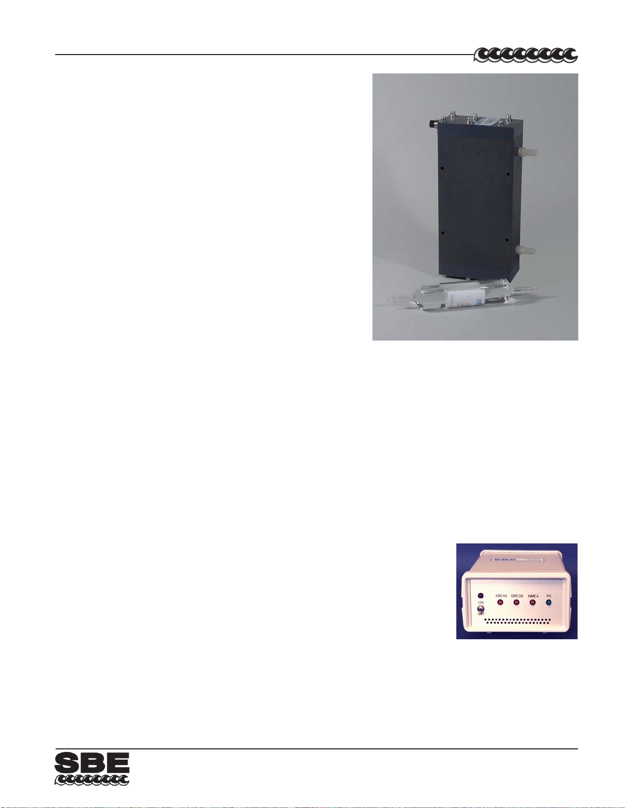
61
MicroTSG (Thermosalinograph)
The SBE 45 MicroTSG Thermosalinograph is an externally
powered, high-accuracy instrument, designed for shipboard
determination of sea surface (pumped-water) conductivity and
temperature. Salinity and sound velocity can also be computed. The
MicroTSG is constructed of plastic and titanium to ensure long life with
minimum maintenance.
OPERATION OVERVIEW
Communication with the MicroTSG is over an internal, 3-wire,
RS-232C link, providing real-time data transmission. Commands can
be sent to the MicroTSG to provide status display, data
acquisition setup, data display and capture, and diagnostic tests. Userselectable operating modes include:
• Polled sampling – On command, the MicroTSG takes one sample
and sends the data to the computer.
• Autonomous sampling – At pre-programmed intervals, the
MicroTSG samples and sends the data to the computer.
The MicroTSG does not enter quiescent (sleep) state between
samples.
• Serial Line Sync – A pulse on the serial line causes the MicroTSG
to wake up, sample, and enter quiescent state automatically .
SBE 45
Calibration coefficients stored in EEPROM allow the MicroTSG to transmit data in engineering units.
SENSORS
The MicroTSG retains the temperature and conductivity sensors used in the SBE 21 Thermosalinograph, but has
improved acquisition electronics that increase accuracy and resolution, and lower power consumption. The MicroTSG’s
aged and pressure-protected thermistor has a long history of exceptional accuracy and stability (typical drift is less than
0.002 °C per year). Electrical isolation of the conductivity electronics eliminates any possibility of ground-loop noise.
The MicroTSG’s internal-field conductivity cell is unaffected by external fouling, and uses expendable
anti-foulant devices.
OPTIONAL PN90402 - SBE 45 POWER, NA VIGATION, and REMOTE TEMPERATURE INTERF ACE BOX
An optional AC- or DC-powered Interface Box:
• Provides isolated DC power and an optically isolated RS-232 data interface.
• Contains a NMEA 0183 port for appending navigation information from a NMEA navigation
device to the data stream.
• Contains an RS-232 port for appending the output of an optional remote temperature
sensor (SBE 38), allowing for measurement of sea surface temperature with minimal
thermal contamination from the ship’s hull.
• Outputs the data stream (MicroTSG , NMEA navigation device, and SBE 38 data) to the
computer over an RS-232 interface.
SOFTWARE
The MicroTSG is supplied with a powerful Win 2000/XP software package, SEASOFT© V2. SEASOFT’s modular
programs include:
• SEA TERM — terminal program for instrument setup and data display .
• Seasave — real-time data acquisition and display
• SBE Data Processing — filtering, aligning, averaging, and plotting of data and derived variables.
Sea-Bird Electronics, Inc.
13431 NE 20th Street, Bellevue, Washington 98005 USA
Website: http://www.seabird.com
E-mail: [email protected]
Telephone: (425) 643-9866
Fax: (425) 643-9954
Page 65
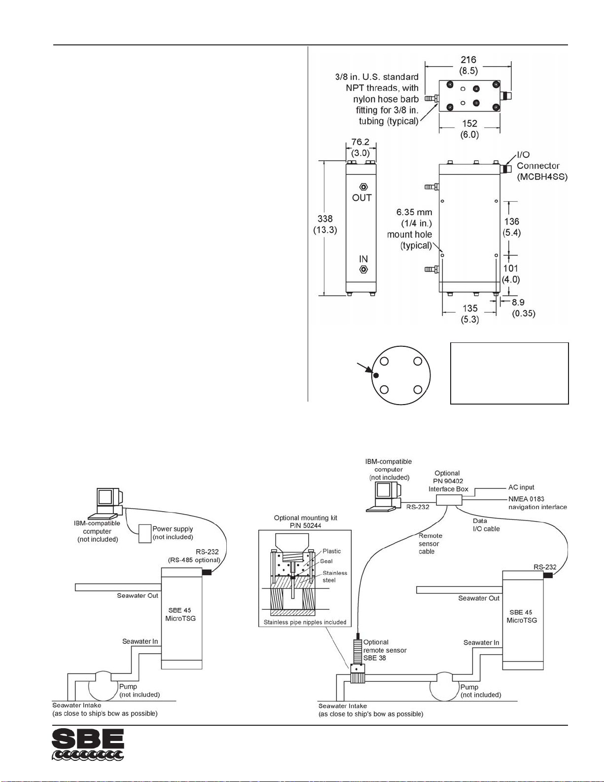
62
MicroTSG (Thermosalinograph)
SPECIFICA TIONS
Measurement Range
Conductivity: 0-7 S/m (0-70 mS/cm)
Temperature *: -5 to 35 °C
Initial Accuracy
Conductivity: 0.0003 S/m (0.003 mS/cm)
Temperature *: 0.002 °C
Salinity: 0.005 PSU, typical
Typical S tability (per month)
Conductivity: 0.0003 S/m (0.003 mS/cm)
Temperature *: 0.0002 °C
Salinity: 0.003 PSU, typical
Resolution
Conductivity: 0.00001 S/m (0.0001 mS/cm)
Temperature *: 0.0001 °C
Salinity: 0.0002 PSU, typical
Calibration Range
Conductivity: 0-6 S/m (60 mS/cm); physical
calibration 2.6-6 S/m (26-60 mS/cm),
plus zero conductivity (air)
Temperature *: +1 to +32 °C
Time Resolution 1 second
Clock Stability 13 seconds/month
Input Power 8-30 VDC
Acquisition Current 34 mA at 8 VDC; 30 mA at 12-30 VDC
Quiescent Current 10 microamps
Acquisition Rate 1 Hz maximum
Operating Pressure 34.5 decibars (50 psi) maximum
Flow Rate 10 to 30 ml/sec (0.16 to 0.48 gal/min)
Materials PVC housing
Weight 4.6 kg (10.2 lbs)
* For specifications for optional SBE 38 remote temperature sensor,
see SBE 38 datasheet.
orientation
For
SBE 45
Dimensions in
millimeters
(inches)
4
1
Pin Signal
3
1 Common
2 RS-232 RX from computer
3 RS-232 TX to computer
4 External power in
2
(8 - 30 VDC)
System Schematic: SBE 45
System Schematic: SBE 45 with Optional PN 90402 Interface Box
and Remote T emperature Sensor
Sea-Bird Electronics, Inc.
13431 NE 20th Street, Bellevue, Washington 9800 5 USA
Website: http://www.seabird.com
12/09
E-mail: [email protected]
Telephone: (425) 643-9866
Fax: (425) 643-9954
Page 66
63
PN 90402 - SBE 45 Power, Navigation, and Remote Temperature Interface Box
For use with SBE 45 MicroTSG
Note: NEW ADDRESS
as of January 18, 2010
User’s Manual
Sea-Bird Electronics, Inc.
13431 NE 20
Bellevue, Washington 98005 USA
Telephone: 425-643-9866 Manual Version #008, 02/02/10
Fax: 425-643-9954 Firmware Version 2.0 and later
E-mail: [email protected] Seasave V7 Version 7.20a and later
Website: www.seabird.com SBE Data Processing Version 7.20a and later
th
Street
Page 67

64
Limited Liability Statement
Extreme care should be exercised when using or servicing this equipment. It should be used or serviced
only by personnel with knowledge of and training in the use and maintenance of oceanographic
electronic equipment.
SEA-BIRD ELECTRONICS, INC. disclaims all product liability risks arising from the use or servicing
of this system. SEA-BIRD ELECTRONICS, INC. has no way of controlling the use of this equipment
or of choosing the personnel to operate it, and therefore cannot take steps to comply with laws
pertaining to product liability, including laws which impose a duty to warn the user of any dangers
involved in operating this equipment. Therefore, acceptance of this system by the customer shall be
conclusively deemed to include a covenant by the customer to defend, indemnify, and hold SEA-BIRD
ELECTRONICS, INC. harmless from all product liability claims arising from the use or servicing of
this system.
2
Page 68

Table of Contents SBE 45 Interface Box
Table of Contents
Section 1: Introduction ........................................................................ 4
About this Manual .............................................................................................4
Unpacking Interface Box ...................................................................................5
Section 2: Interface Box Description.................................................. 6
System Description............................................................................................6
Specifications.....................................................................................................7
System Communications ...................................................................................7
Connections, Switches, and LEDs .....................................................................8
Data Output Format ...........................................................................................9
Section 3: Setting Up System ............................................................ 10
Installing Software...........................................................................................10
Communications Test and Setup......................................................................11
Commands .......................................................................................................14
Setting Up Instruments ....................................................................................17
SBE 45......................................................................................................17
SBE 38......................................................................................................17
NMEA Navigation Device........................................................................18
Setting Up SBE 45 Configuration (.xmlcon or .con) File in Seasave ..............19
65
Section 4: Operating System ............................................................. 20
Acquiring Real-Time Data with Seasave.........................................................20
Processing Data with SBE Data Processing.....................................................21
Section 5: Routine Maintenance ....................................................... 22
Section 6: Troubleshooting................................................................ 23
Problem 1: Unable to Communicate with Interface Box .................................23
Problem 2: Unable to Communicate with SBE 45 through Interface Box.......23
Problem 3: Unable to Communicate with SBE 38 through Interface Box.......24
Problem 4: Unable to Communicate with NMEA Navigation Device
through Interface Box .....................................................................................
Problem 5: Nonsense or Unreasonable Data....................................................24
Problem 6: Changing SBE 45 and/or SBE 38 Baud Rate without Cables
for Direct Connection .....................................................................................
24
25
Glossary .............................................................................................. 26
Safety and Electrical Symbols .........................................................................26
Appendix I: NMEA Data................................................................... 27
NMEA Raw Message Formats ........................................................................27
Troubleshooting NMEA ..................................................................................28
Problem 1: Yellow NMEA LED Not Flashing..........................................28
Problem 2: Yellow NMEA LED Flashing,
but Lat/Lon Data Not Displaying .............................................................
NMEA Simulation Program ............................................................................29
28
Appendix II: Replacement Parts ...................................................... 31
Index.................................................................................................... 32
3
Page 69

66
Section 1: Introduction SBE 45 Interface Box
Section 1: Introduction
This section includes photos of a standard PN 90402 – SBE 45 Power,
Navigation, and Remote Temperature Interface Box shipment.
About this Manual
This manual is to be used with the PN 90402 – SBE 45 Power, Navigation,
and Remote Temperature Interface Box for the SBE 45 MicroTSG. It is
organized to guide the user from installation through operation. We have
included specifications, setup and operation descriptions, and helpful notes
throughout the manual.
Sea-Bird welcomes suggestions for new features and enhancements of our
products and/or documentation. Please contact us with any comments or
suggestions ([email protected] or 425-643-9866). Our business hours are
Monday through Friday, 0800 to 1700 Pacific Standard Time (1600 to 0100
Universal Time) in winter and 0800 to 1700 Pacific Daylight Time (1500 to
0000 Universal Time) the rest of the year.
4
Page 70
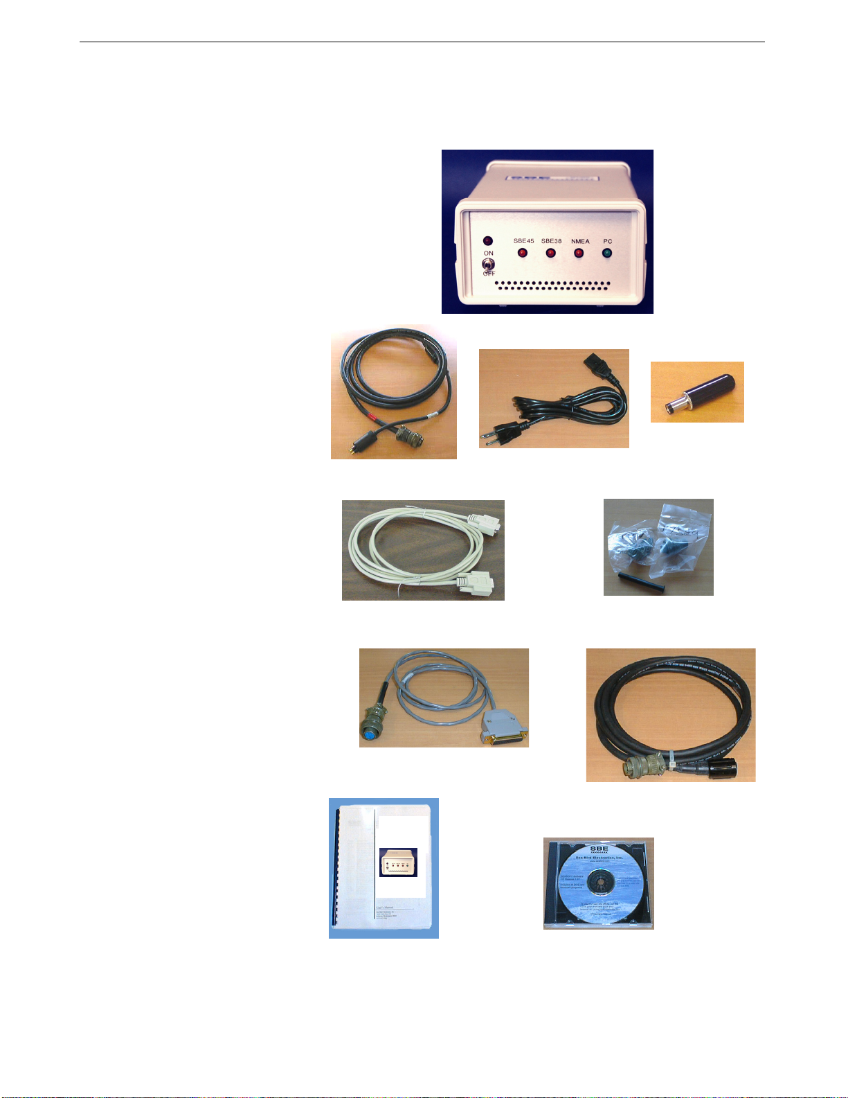
Section 1: Introduction SBE 45 Interface Box
Unpacking Interface Box
Shown below is a typical PN 90402 – SBE 45 Power, Navigation, and Remote
Temperature Interface Box shipment.
Cable -
SBE 45 to Interface Box
I/O cable (Interface Box
to computer)
Navigation Interface test cable
(Interface Box to NMEA navigation
device simulation computer)
PN 90402 -
SBE 45 Power, Navigation,
and Remote Temperature
Interface Box
For use with SBE 45
MicroTSG
Interface Box
Manual
Interface Box
DC power
connector
AC power cable
Connectors for SBE 45,
SBE 38, and NMEA
(3 connectors/Interface Box)
(optional) Cable -
SBE 38 to Interface Box
Software, and Electronic Copies of
Software Manuals and User Manual
67
5
Page 71

68
Section 2: Interface Box Description SBE 45 Interface Box
Section 2: Interface Box Description
This section describes the functions and features of the Interface Box, system
communications, and output data format.
System Description
The PN 90402 – SBE 45 Power, Navigation, and Remote Temperature
Interface Box provides continuous power and an opto-isolated RS-232C
interface for the SBE 45 MicroTSG Thermosalinograph. Additionally, the
Interface Box provides:
• An opto-isolated NMEA receiver for an optional NMEA navigation
device (not supplied by Sea-Bird)
• Power and an RS-232C interface for an optional SBE 38 remote
temperature sensor
Baud rates between the Interface Box and SBE 45, SBE 38, NMEA navigation
device, and computer are user-programmable.
The Interface Box merges position data and SBE 38 remote temperature data
with SBE 45 data. The NMEA Interface decodes messages that are output
Notes:
• Help files provide detailed
information on software use.
• NMEATest, a NMEA navigation
device simulation program, is
part of the SBE Data Processing
installation.
• Separate software manuals on CDROM contain detailed information on
the setup and use of Seasave V7
and SBE Data Processing.
• Sea-Bird also supplies an older
version of Seasave, SeasaveWin32. However, all Seasave
instructions in this manual are
written for Seasave V7. See
Seasave-Win32’s manual and/or
Help files if you prefer to use the
older software.
from navigation devices supporting NMEA 0183 protocol, outputting data in
GGA, GLL, RMA, RMC, or TRF format. Decoded Latitude, Longitude, date,
and time and SBE 38 temperature data are appended to the SBE 45 data stream
in the Interface Box. The data, in ASCII engineering units, is passed to the
computer for storage and/or display.
The Interface Box can be AC- or DC-powered:
• AC power - universal 85-265 VAC input with frequency of 47-63 Hz
• DC power - 10-28 VDC input.
The Interface Box is supplied with a powerful Win 2000/XP software package,
SEASOFT V2, which includes:
• SEATERM – terminal program for easy setup.
• Seasave V7 – program for acquiring, converting, and displaying real-time
or archived raw data.
• SBE Data Processing – program for calculation and plotting of
conductivity, temperature, pressure, auxiliary sensor data, and derived
variables such as salinity and sound velocity.
6
Page 72
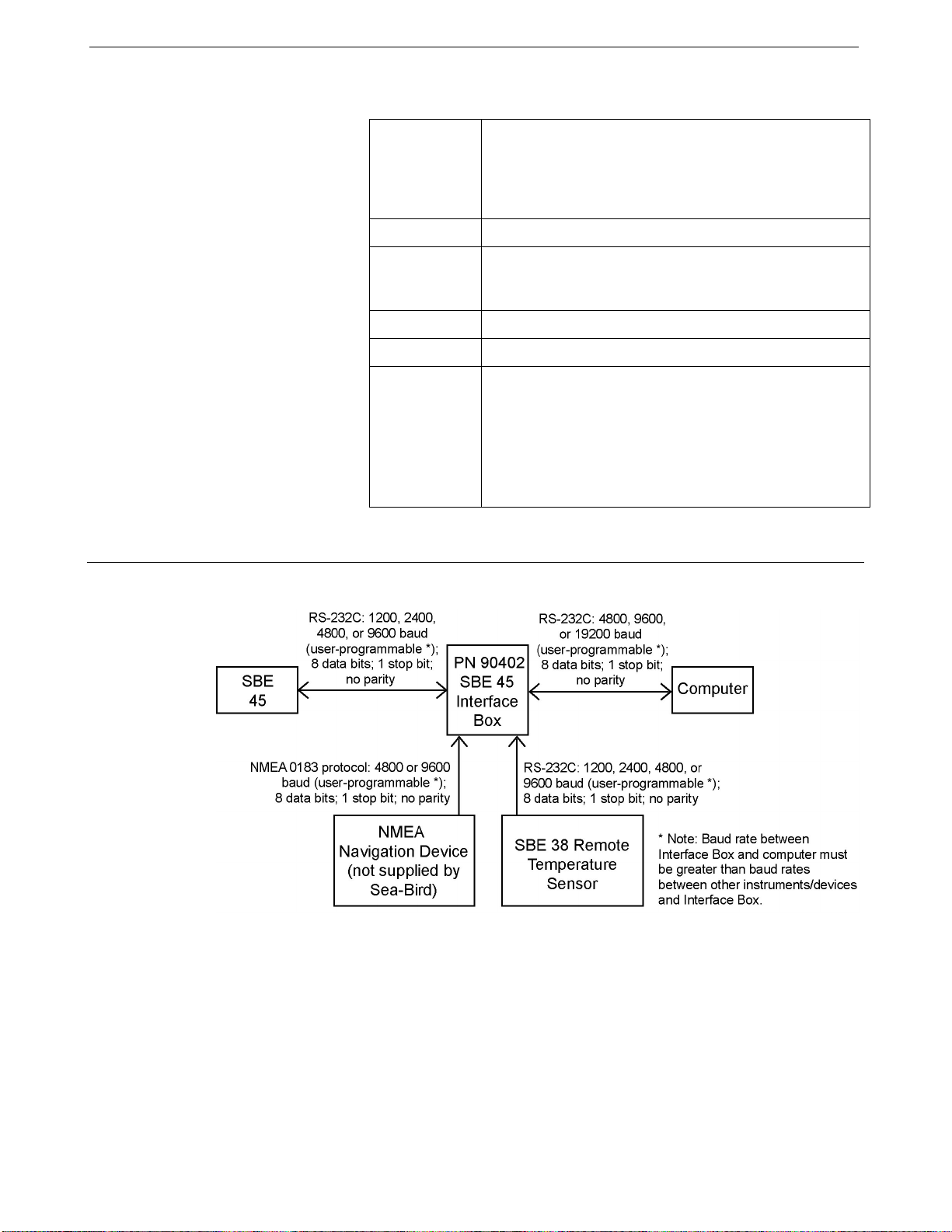
Section 2: Interface Box Description SBE 45 Interface Box
Specifications
Power
Requirements
AC: 100-240 VAC / 47-63Hz / 0.25A,
The Interface Box should always be used with a threeterminal outlet that includes a protective earth.
or
DC: 10-28 VDC / 0.10A
69
System Communications
Fuse
Operating
Current
Dimensions
Weight
Installation
Environment
5x20mm, 250VAC Slow-Blow, 0.5 Amp
Interface Box alone: 27 mA
Interface Box with SBE 45: 65 mA
Interface Box with SBE 45 and 38: 80 mA
200 x 121 x 76 mm (7.875 x 4.75 x 3 inch)
1.1 kg (2.5 lbs)
Interface Box operates properly under the following
conditions:
• Indoor use
• Altitude up to 2000 meters
• Temperature from 5 °C to 40 °C
• Maximum relative humidity 80%, non-condensing
• Mains supply voltage ±10%
7
Page 73
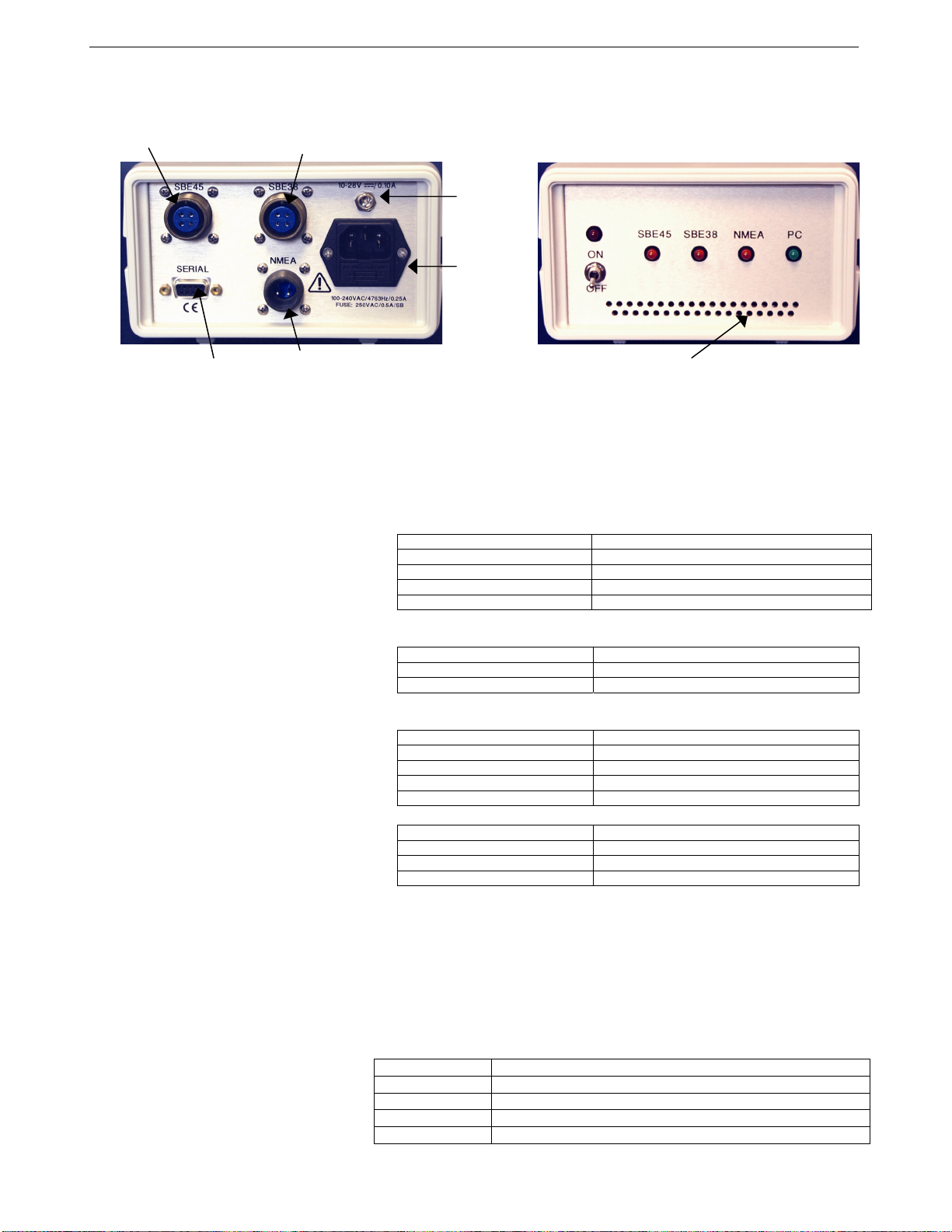
70
Section 2: Interface Box Description SBE 45 Interface Box
Connections, Switches, and LEDs
Communications with
and power to SBE 45
To computer
Communications with
and power to SBE 38
Output from NMEA device
Connections:
Cables longer than 3 meters should be installed inside an earthed metal conduit
by a qualified electrician. This minimizes the potential for external signals to
disrupt communication and ensures that high voltage lines (such as the sea
cable) are sufficiently protected. Cables shorter than 3 meters can be used
without shielding when installing or bench testing the instrument.
• SBE 45 - to SBE 45 MicroTSG; use supplied 4-pin MS-3106A-14S-2P
• NMEA - to NMEA navigation device; use supplied 2-pin
• SBE 38 - to SBE 38 remote temperature sensor; use supplied 4-pin
• Serial - to computer with supplied DB-9P/DB-9S cable.
• AC Input - to standard, 3-prong, grounded, VAC power supply, using the
Power Switch and Red LED:
Switch turns power to Interface Box on/off. Red LED turns on to indicate
power is on.
LEDs:
Indicate if Interface Box is communicating with other parts of system:
DC
Input
AC
input
Ventilation
connector or supplied cable:
Interface Box Function
Pin A Common
Pin B RS-232 data transmit to SBE 45
Pin C RS-232 data receive from SBE 45
Pin D Power to SBE 45
MS-3106A12S-3S connector or supplied test cable:
Interface Box Function
Pin A NMEA A (signal)
Pin B NMEA B (signal return)
MS-3106A-14S-2P connector or optional cable:
Interface Box Function
Pin A Common
Pin B RS-232 data transmit to SBE 38
Pin C RS-232 data receive from SBE 38
Pin D Power to SBE 38
Interface Box Function
Pin 2 RS-232 data transmit to computer
Pin 3 RS-232 data receive from computer
Pin 5 Ground
supplied UL/IED-approved power cord, or
DC Input - to VDC power supply.
LED: Flashes when carriage return (decimal 13) received from:
Yellow SBE 45 SBE 45
Yellow SBE 38 SBE 38
Yellow NMEA NMEA navigation device
Green PC Computer
8
Page 74

Section 2: Interface Box Description SBE 45 Interface Box
Data Output Format
The time between each output scan is governed by the SBE 45’s setup.
The Interface Box outputs the most recent data from the SBE 38 and/or
NMEA navigation device with each scan of SBE 45 data. The Interface Box
outputs data in the following format and order:
Format=0 (standard format)
Notes:
• Inclusion of all parameters except
for t1 (temperature from SBE 45) is
dependent on configuration – if the
system does not include the
specified instrument or the
parameter is not enabled, the
corresponding data is not included in
the output data stream, shortening
the data string.
• Not all NMEA navigation devices
transmit time and / or date.
• The SBE 45 must be set up to
output data with OutputFormat=0 or
1 (SBE 45 OutputFormat=2 is not
compatible with the Interface Box).
Note:
When using Format=1:
• Set up the SBE 45 with:
¾ OutputFormat=0 or 1,
¾ OutputSV=Y, and
¾ OutputCond=Y and/or
OutputSal=Y
and connect an SBE 38 to the
Interface Box.
• The Interface Box will not output any
parameters other than what is
shown at right, regardless of settings
in the SBE 45 or connection of the
Interface Box to a NMEA navigation
device.
• Format=1 is not compatible with
Seasave real-time data acquisition
software or SBE Data Processing
post-processing software.
t1=ttt.tttt, c1=cc.ccccc, s = sss.ssss, sv=vvvv.vvv,
t2 = ttt.tttt, lat = DD MM.MMMM W, lon = DDD MM.MMMM W,
hms = HHMMSS, dmy = DDMMYY
where
• t1 = temperature from SBE 45 (°C, ITS-90).
• c1 = conductivity from SBE 45 (S/m);
output if OutputCond=Y in SBE 45.
• s = salinity (psu) calculated from t1 and c1 by SBE 45;
output if OutputSal=Y in SBE 45.
• sv = sound velocity (m/sec); output if OutputSV=Y in SBE 45.
¾ If the Interface Box is acquiring data from an SBE 38 remote
temperature sensor and if the SBE 45 is set to OutputCond=Y or
OutputSal=Y: the Interface Box recalculates sound velocity based
on s (or t1 and c1) from the SBE 45 and temperature t2 from the
SBE 38. This provides the most accurate sound velocity results,
because sound velocity is a function of salinity and temperature, and
the SBE 38 typically provides more accurate sea surface temperature
than the thermosalinograph, since it is closer to the seawater intake.
¾ Otherwise: the Interface Box outputs sound velocity calculated from
t1 and c1 by the SBE 45.
• t2 = temperature from SBE 38 (°C, ITS-90 if Format=C in SBE 38;
number of digits after decimal point is set with Digits= in SBE 38).
• lat = latitude from NMEA navigation device.
DD = degrees.
MM.MMMM = minutes and fractions of minutes; number of digits after
decimal point is number of digits in received NMEA string.
W = N (north) or S (south).
• lon = longitude from NMEA navigation device.
DDD = degrees.
MM.MMMM = minutes and fractions of minutes; number of digits after
decimal point is number of digits in received NMEA string.
W = E (east) or W (west).
• hms = time from NMEA navigation device (hour, minute, second).
• dmy = date from NMEA navigation device (day, month, year).
All data is separated with a comma and a space. Each scan ends with a
carriage return <CR> and line feed <LF>. Leading zeros are suppressed,
except for one zero to the left of the decimal point.
Format=1 (custom format for interfacing with a Kongsberg EM 300
Multibeam Echo Sounder)
tt.ttt vvvv.v
where
• tt.ttt = temperature from SBE 38 remote temperature sensor (°C, ITS-90).
• vvvv.v = sound velocity (m/sec) calculated in Interface Box from:
¾ salinity based on conductivity and temperature measured by
SBE 45, and
¾ temperature measured by SBE 38 remote temperature sensor
Temperature and sound velocity data is separated with a space. Each scan ends
with a carriage return <CR> and line feed <LF>. Leading zeros are
suppressed, except for one zero to the left of the decimal point.
71
9
Page 75

72
Section 3: Setting Up System SBE 45 Interface Box
Section 3: Setting Up System
This section covers:
• Installing Sea-Bird software
• Communications testing and setup
• System commands
• Setting up the SBE 45 configuration (.xmlcon or .con) file
Installing Software
Sea-Bird recommends the following minimum system requirements for
SEASOFT V2: Windows 2000 or later, 500 MHz processor, 256 MB RAM,
and 90 MB free disk space for installation. Although SEASOFT V2 was
designed to work with a PC running Win 2000/XP; extensive testing has not
Notes:
• Help files provide detailed
information on the software.
• NMEATest, a NMEA navigation
device simulation program, is
part of the SBE Data Processing
installation.
• Separate software manuals on CDROM contain detailed information on
the setup and use of Seasave V7
and SBE Data Processing.
• Sea-Bird also supplies an older
version of Seasave, SeasaveWin32. However, all Seasave
instructions in this manual are
written for Seasave V7. See
Seasave-Win32’s manual and/or
Help files if you prefer to use the
older software.
• Sea-Bird supplies the current
version of our software when you
purchase an instrument. As software
revisions occur, we post the revised
software on our FTP site. See our
website (www.seabird.com) for the
latest software version number, a
description of the software changes,
and instructions for downloading the
software from the FTP site.
shown any compatibility problems when using the software with a PC running
Windows Vista.
If not already installed, install Sea-Bird software on your computer using the
supplied software CD.
1. Insert the CD in your CD drive.
2. Install software: Double click on SeasoftV2_date.exe (date is the date
that version of the software was created). Follow the dialog box directions
to install the software. The installation program allows you
to install the desired components. Install all the components, or just
install SEATERM (terminal program), Seasave V7 (real-time data
acquisition), and SBE Data Processing (data processing).
The default location for the software is c:\Program Files\Sea-Bird. Within that
folder is a sub-directory for each program.
10
Page 76
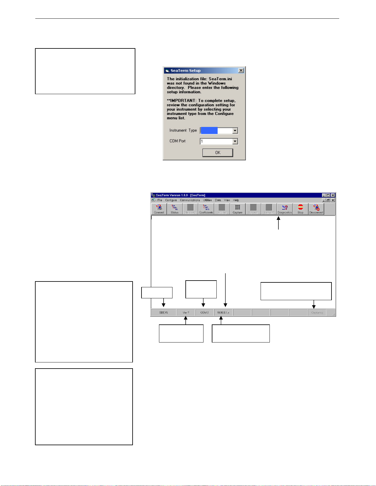
Section 3: Setting Up System SBE 45 Interface Box
Communications Test and Setup
Notes:
• See SEATERM’s Help files.
The Interface Box is not available
•
in the list of instrument types.
Select SBE 45 as the instrument
type.
1. With power to the Interface Box off, double click on SeaTerm.exe. If this
is the first time SEATERM is used, the setup dialog box may appear:
SBE 45
Select the instrument type (SBE 45 TSG) and the computer COM port for
communication with the Interface Box. Click OK.
2. The main screen looks like this:
73
Note:
There is at least one way, and as
many as three ways, to enter
a command:
• Manually type a command in
Command/Data Echo Area
• Use a menu to automatically
generate a command
• Use a Toolbar button to
automatically generate
a command
Note:
Once the system is configured and
connected (Steps 3 and 4 below),
to update the Status bar:
• on the Toolbar, click Status; or
• from the Utilities menu, select
Instrument Status.
SEATERM sends the status
command, which displays in the
Command/Data Echo Area, and
updates the Status bar.
Menus
Toolbar
Command/Data Echo Area
Status bar
Computer
Instrument
Instrument
EPROM version
COM port
Baud rate, data bits,
stop bits, and parity
• Menus – Contains tasks and frequently executed instrument commands.
• Toolbar – Contains buttons for frequently executed tasks and instrument
commands. All tasks and commands accessed through the Toolbar are
also available in the Menus. To display or hide the Toolbar, select View
Toolbar in the View menu. Grayed out Toolbar buttons are not applicable.
• Command/Data Echo Area – Echoes a command executed using a Menu
or Toolbar button, as well as the instrument’s response. Additionally, a
command can be manually typed in this area, from the available
commands for the instrument.
• Status bar – Provides status information. To display or hide the Status bar,
select View Status bar in the View menu.
Capture to file status – grayed
out if not capturing
11
Page 77
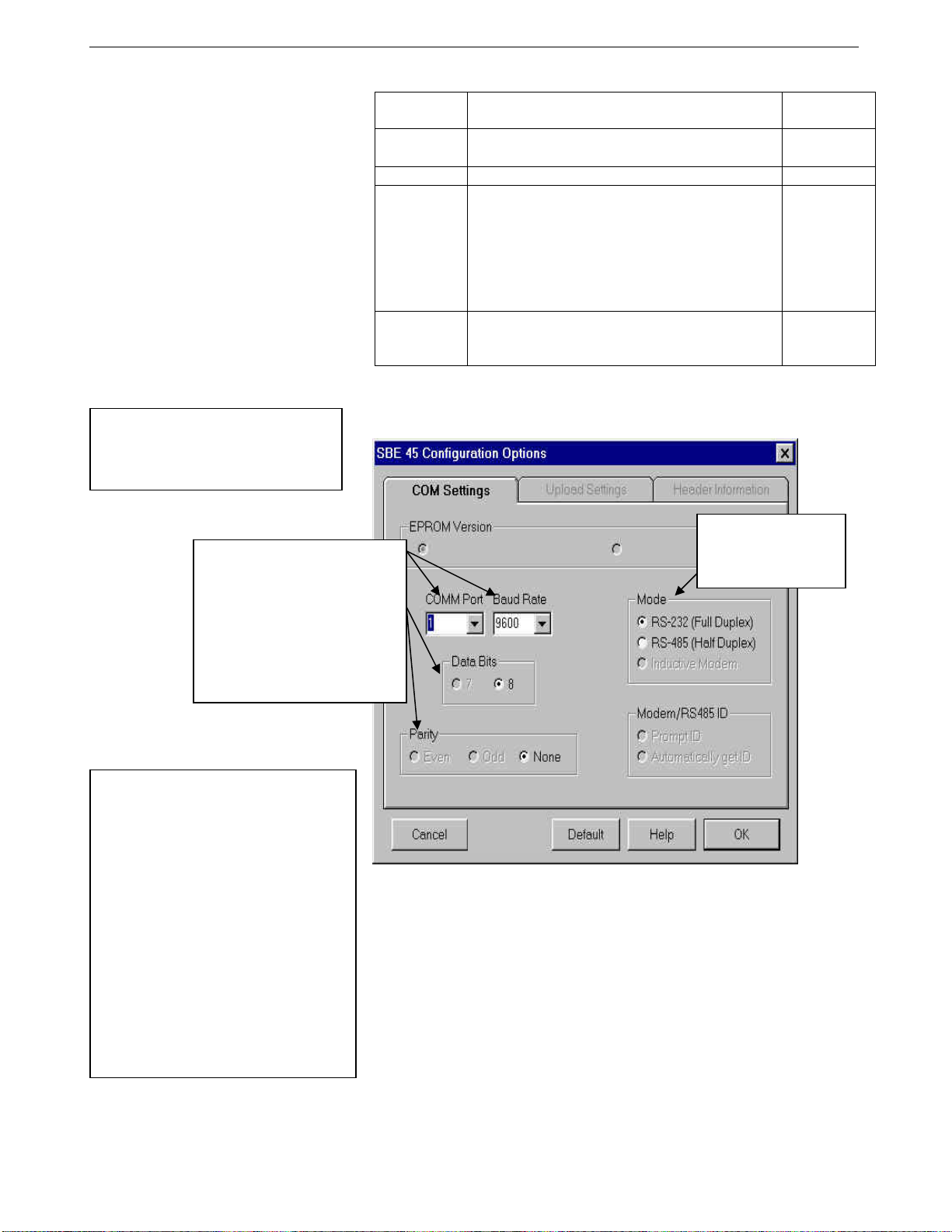
74
Section 3: Setting Up System SBE 45 Interface Box
Following are the Toolbar keys applicable to the Interface Box:
Toolbar
Keys
Connect
Re-establish communications with Interface Box.
Computer responds with S> prompt.
Description
Status Display instrument status.
Equivalent
Command*
(press Enter
key)
DS
Capture instrument responses on screen to file.
Interface Box has no internal memory; you must
capture before sampling begins to save data
Capture
for future review and processing, or use
—
Seasave for data acquisition. File has .cap
extension. Press Capture again to turn off
capture. Capture status displays in Status bar.
Free computer COM port used to communicate
Disconnect
with Interface Box. COM port can then be used
—
by another program.
*See Command Descriptions.
Note:
The Interface Box is not available in
the list of instrument types. Select
SBE 45 as the instrument type.
3. In the Configure menu, select SBE 45 TSG. The dialog box looks
like this:
Computer COM port, baud rate,
data bits, and parity for
communication between computer
and Interface Box.
Select 4800, 9600, or 19200 baud
(set this greater than baud rate
you will use to communicate
between Interface Box
and SBE 45, SBE 38, and
NMEA navigation device).
Notes:
• SEATERM’s baud rate must be the
same as the Interface Box baud rate
(set with PCBaud=). Baud is factoryset to 9600, but can be changed by
the user (see Commands).
• When you click OK, SEATERM
saves the Configuration Options
settings to the SeaTerm.ini file in
your Windows directory.
SeaTerm.ini contains the last saved
settings for each instrument
(SBE 37, 45, etc.). When you open
SEATERM and select the desired
instrument in the Configure menu,
the Configuration Options dialog box
shows the last saved settings for
that instrument.
Interface for
communication between
computer and Interface
Box. Select RS-232.
Make the selections in the Configuration Options dialog box. Click OK to
save the settings.
4. Turn on power to the Interface Box. The display looks like this (if the
Interface Box is set up to power-up in Normal mode with the
IMode=NORMAL command; see Commands for details):
SBE45 Junction Box V 1.4
mode is normal
If the system does not respond as described:
• Click Connect on the Toolbar to attempt to establish communications.
• Verify the SBE 45 was selected in the Configure menu and settings
were entered correctly in the Configuration Options dialog box.
• Check cabling between the computer and the Interface Box.
• If the response shows
mode is connect45, the Interface Box is set
up to power-up in SBE 45 mode (IMode=CONNECT45). Type @ to
return to Normal mode for communication with the Interface Box.
12
Page 78
Section 3: Setting Up System SBE 45 Interface Box
5. If the SBE 45 was set to AutoRun=Y and its J1 jumper was set to pins 1
and 2 (begin sampling automatically on power up), data from the Interface
Box begins scrolling on the screen. Each time data is received from an
Note:
The Interface Box outputs data at the
SBE 45’s data output rate. If the
SBE 45 is not outputting any data,
data from the SBE 38 and/or NMEA
navigation device will not appear at all.
instrument (SBE 45, SBE 38, and NMEA navigation device), the
corresponding LED on the Interface Box flashes. If data is
not received, is incorrect, or is not updating properly for some or
all instruments:
• Verify that the instrument is connected to the Interface Box and that
the proper cable is used.
• Check the baud rate of each instrument (SBE 45, SBE 38, and NMEA
navigation device). These baud rates must be less than the baud rate
for communication between the Interface Box and the computer. If
necessary, connect each instrument directly to the computer and use
SEATERM to reset its baud rate. See the appropriate instrument
manual for details.
• Check that the setup of each instrument is compatible with operation
with the Interface Box. See Setting Up Instruments.
• If data is not received from a NMEA navigation device, see
Appendix I: NMEA Data for troubleshooting information.
6. If desired, type Stop and press the Enter key to stop the scrolling data.
Note that you can send commands to the Interface Box and/or attached
instruments while it is transmitting data, but it easier to see what the
commands and responses are without the scrolling data.
7. Display Interface Box status information by clicking Status on the
Toolbar. The display looks like this:
SBE45 Junction Box V 1.4
SBE 45 baud rate = 4800
SBE 38 baud rate = 4800
NMEA baud rate = 4800
standard output format
Note that the baud rates shown must be less than the baud rate for
communication between the Interface Box and the computer.
8. Verify SBE 45 setup by putting the Interface Box in SBE 45 mode:
A. Type Connect45 and press the Enter key. If the SBE 45 is set for
AutoPower=Y and SingleSample=N, SBE 45 data will scroll across
the screen. Type Stop and press the Enter key to stop the scrolling
data.
B. Send desired setup commands to the SBE 45 (see Setting Up
Instruments for required setup parameters).
C. Type GO and press the Enter key to restart SBE 45 sampling. SBE 45
data should begin scrolling on the screen.
Note:
You must restart SBE 45 and SBE 38
sampling using Go before returning to
Normal mode, or these instruments
will not transmit their data to the
Interface Box.
D. Type @ to return to Normal mode for communication with the
Interface Box.
9. Verify SBE 38 setup by putting the Interface Box in SBE 38 mode:
A. Type Connect38 and press the Enter key. If the SBE 38 is set for
AutoPower=Y, SBE 38 data will scroll across the screen. Type Stop
and press the Enter key to stop the scrolling data.
B. Send desired setup commands to the SBE 38 (see Setting Up
Instruments for required setup parameters).
C. Type Go and press the Enter key to restart SBE 38 sampling. SBE 38
data should begin scrolling on the screen.
D. Type @ to return to Normal mode for communication with the
Interface Box.
10. Type Start and press the Enter key to restart data transmission through
the Interface Box.
The system is ready for deployment.
75
13
Page 79

76
Section 3: Setting Up System SBE 45 Interface Box
Commands
This section describes commands and provides sample outputs.
When entering commands:
• Input commands to the Interface Box in upper or lower case letters and
register commands by pressing the Enter key.
• The Interface Box sends ? if an invalid command is entered.
• If the system does not return an S> prompt after executing a command,
press the Enter key to get the S> prompt.
• The Interface Box can accept commands while transmitting data. Type in
any command and press the Enter key; the S> is not required.
Status Command
DS Display firmware version and baud rate
settings. Equivalent to Status button
on Toolbar.
List includes, where applicable, command
used to modify parameter.
• firmware version
• SBE 45 baud rate [45Baud=]
• SBE 38 baud rate [38Baud=]
• NMEA baud rate [NMEABaud=]
• output format [Format=] –
standard output format or
output format 1
Note:
Baud rate for communication
between Interface Box and
computer must be greater than baud
between Interface Box and SBE 45,
SBE 38, and NMEA navigation
device.
Example: (user input shown in bold)
S>DS
SBE45 Junction Box V 1.4
SBE 45 baud rate = 4800 [45Baud=]
SBE 38 baud rate = 4800 [38Baud=]
NMEA baud rate = 4800 [NMEABaud=]
standard output format [Format=]
Baud Rate Commands
PCBaud=x x= baud rate for communication between
Interface Box and computer
(4800, 9600, or 19200). Default 9600.
45Baud=x x= baud rate for communication between
Interface Box and SBE 45 (1200, 2400,
4800, or 9600). Default 4800. Must match
baud set in SBE 45 with Baud=.
38Baud=x x= baud rate for communication between
Interface Box and optional SBE 38 (1200,
2400, 4800, or 9600). Default 4800. Must
match baud set in SBE 38 with Baud=.
NMEABaud=x x= baud rate for communication between
Interface Box and optional NMEA
navigation device (4800 or 9600).
Default 4800. Must match baud of
NMEA navigation device.
14
Page 80

Section 3: Setting Up System SBE 45 Interface Box
Mode Commands
IMode=x x=Normal: On power-up, Interface Box is
Notes:
• IMode=Connect45 is not
compatible with Seasave real-time
data acquisition software.
• Type @ or press the Esc key to
exit SBE 45, SBE 38, or NMEA
mode and return to Normal mode
for communicating with the
Interface Box.
in Normal mode for communicating with
Interface Box.
x=Connect45: On power-up,
Interface Box is in SBE 45 mode, for
communicating with SBE 45 through
Interface Box. Equivalent to powering up
in Normal mode, and then immediately
sending Connect45. When you send
IMode=Connect45, Interface Box is also
immediately placed in SBE 45 mode.
Example: (user input shown in bold)
With the Interface Box in Normal mode, turn power on. Interface Box responds as follows:
S>SBE 45 Junction Box V 1.4
mode is normal
S>IMODE=CONNECT45 (send command to change start-up mode; also switches to SBE 45 mode now)
Connected to SBE 45, press @ or Esc to return to normal mode
S>DS (transmitted to SBE 45, so status response is from SBE 45)
SBE45 V 1.1 SERIAL NO. 0059
. . . . (see SBE 45 manual for remainder of SBE 45 status response)
S> (send other commands to SBE 45 as desired)
@ (put Interface Box back in normal mode)
mode switched back to normal
S>DS (transmitted to Interface Box, so status response is from Box)
SBE45 Junction Box V 1.4
. . . . (see above for remainder of Interface Box status response)
Turn power off and then on again. Interface Box starts up in SBE 45 mode:
S>SBE 45 Junction Box V 1.4
Mode is connect 45
SBE45 V 1.1
S> (send commands to SBE 45 as desired)
77
Connect45 Put Interface Box in SBE 45 mode,
allowing you to send commands to
SBE 45 through Interface Box.
Example: (user input shown in bold)
S>CONNECT45
Connected to SBE 45, press @ or Esc to return to normal mode
S>DS (transmitted to SBE 45, so status response is from SBE 45)
SBE45 V 1.1 SERIAL NO. 0059
. . . . (see SBE 45 manual for remainder of SBE 45 status response)
S>OUTPUTSV=N (do not output sound velocity from SBE 45)
@
mode switched back to normal
S>DS (transmitted to Interface Box, so status response is from Interface Box)
SBE45 Junction Box V 1.4
. . . . (see above for remainder of Interface Box status response)
Connect38 Put Interface Box in SBE 38 mode,
allowing you to send commands to
SBE 38 through Interface Box.
ConnectNMEA Put Interface Box in NMEA mode,
allowing you to look at data as transmitted
by NMEA navigation device.
15
Page 81

78
Section 3: Setting Up System SBE 45 Interface Box
Output Format Command
Note:
See Data Output Format in Section 2:
Interface Box Description for details.
• Format=1 is not compatible with
Seasave real-time data acquisition
software or SBE Data Processing
post-processing software.
Format=x x=0: Output standard format (default)
t1=ttt.tttt, c1=cc.ccccc, s =
sss.ssss, sv=vvvv.vvv, t2 =
ttt.tttt, lat = DD MM.MMMM W,
lon = DDD MM.MMMM W, hms =
HHMMSS, dmy = DDMMYY
x=1: Output custom format for Kongsberg
EM 300 Multibeam Echo Sounder
tt.ttt vvvv.v
Note:
Interface Box starts transmitting data
automatically when power is turned on
and stops when power is removed.
Use Stop to stop transmitting data
temporarily while setting up the
instruments, and then restart
transmitting data by sending Start.
Sampling Commands
Start Start transmitting data.
Stop Stop transmitting data.
Diagnostic Command
*EETest Test EEPROM; reset baud rates to defaults
(new bauds take effect on next power up).
Example: (user input shown in bold)
S>*eetest
wr: 128
. .
wr: 1920
rd: 256
. .
rd: 1792
passed EEprom test
S>
16
Page 82

Section 3: Setting Up System SBE 45 Interface Box
Setting Up Instruments
Notes:
• In SEATERM, use the @
character or press the Esc key to
exit SBE 45 mode, SBE 38 mode,
or NMEA mode and return to
Normal mode for communicating
with the Interface Box.
• If you reset the baud rate, you
may need to turn power off and
then on again to resume
communications at the new baud
rate.
• SBE 45 OutputFormat=2 is not
compatible with the Interface Box.
SBE 45
Set the SBE 45 J1 jumper to Autopower (pins 1 and 2) for use with the
Interface Box (this is the default setting when the SBE 45 is shipped).
With the SBE 45 directly connected to the computer, set the SBE 45 baud rate
with Baud= to match the baud rate set in the Interface Box with 45Baud=.
The remaining setup can be performed with the SBE 45 directly connected to
the computer, or through the Interface Box. With the Interface Box connected
to the computer and SBE 45, send Connect45 to the Interface Box to put the
Interface Box in SBE 45 mode and send commands to the SBE 45 through the
Interface Box.
• Set up the SBE 45 to begin sampling when power is applied by sending
AutoRun=Y and SingleSample=N.
• Set up the SBE 45 to output data in the following order: temperature,
conductivity, salinity, and sound velocity by sending OutputFormat=0 or
OutputFormat=1.
Note: The SBE 45 always outputs temperature. Conductivity is output if
OutputCond=Y, salinity is output if OutputSal=Y, and sound velocity is
output if OutputSal=Y.
• Set the other sampling and output parameters for the SBE 45 as desired
(see the SBE 45 manual).
SBE 38
With the SBE 38 directly connected to the computer:
• Set the SBE 38 baud rate with Baud= to match the baud rate set in the
Interface Box with 38Baud=.
• Set up the SBE 38 to communicate using RS-232 with Interface=232.
The remaining setup can be performed with the SBE 38 directly connected to
the computer, or through the Interface Box. With the Interface Box connected
to the computer, SBE 45, and SBE 38, send Connect38 to the Interface Box to
put the Interface Box in SBE 38 mode and send commands to the
SBE 38 through the Interface Box.
• Set up the SBE 38 to begin sampling when power is applied by sending
AutoRun=Y.
• Set the output format and number of digits with Format= and Digits=.
You must set the format to converted data (Format=C) if you will
process the data with SBE Data Processing.
• Set the other sampling parameters for the SBE 38 as desired (see the
SBE 38 manual).
79
17
Page 83
80
Section 3: Setting Up System SBE 45 Interface Box
NMEA Navigation Device
The Interface Box is designed to decode messages that are output from
navigation devices supporting NMEA 0183 protocol, outputting messages in
GGA, GLL, RMA, RMC, or TRF format. Verify that the navigation device
baud rate matches the baud rate set in the Interface Box with NMEABaud=
(4800 or 9600).
Note:
Not all NMEA navigation devices
transmit time and / or date.
The most recent decoded Latitude, Longitude, time, and date data is appended
to the end of the SBE 45 data stream in the Interface Box and passed to the
computer for storage and/or display with the SBE 45 data. Position data format
is detailed in Appendix I: NMEA Data. The Yellow NMEA LED on the
Interface Box flashes each time a NMEA message is received (should be the
same rate at which your navigation device is transmitting).
Example 1: SBE 45 is set up to output data once every 10 seconds. A navigation device
outputs its NMEA message once every 5 seconds. The Yellow NMEA LED flashes
every 5 seconds. However, only the most recent NMEA message is appended to each
scan of SBE 45 data.
Example 2: SBE 45 is set up to output data once every 1 second. A navigation device
outputs its NMEA message once every 5 seconds, and the Yellow NMEA LED flashes
every 5 seconds. The same message is appended to each scan of SBE 45 data within
that 5 seconds.
While communicating with the Interface Box, send the ConnectNMEA
command to view the raw NMEA data.
18
Page 84
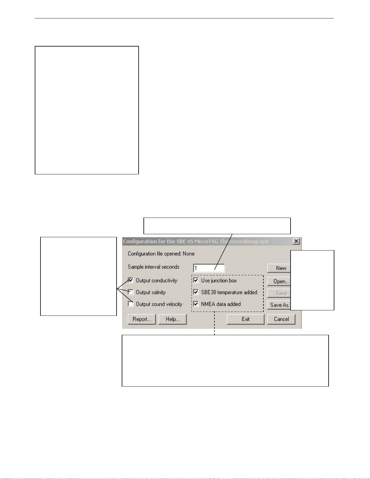
Section 3: Setting Up System SBE 45 Interface Box
Setting Up SBE 45 Configuration (.xmlcon or .con) File in Seasave
Notes:
• Seasave and SBE Data Processing
versions 7.20a introduced .xmlcon
files (in XML format). Versions 7.20a
and later allow you to open a .con or
.xmlcon file, and to save it to a .con
or .xmlcon file. Seasave and SBE
Data Processing use the same file.
• A new or recalibrated CTD ships
with a configuration file that reflects
the current configuration as we know
it. The file is named with the
instrument serial number, followed
by a .con extension. For example,
for a CTD with serial number 2375,
Sea-Bird names the file 2375.con.
You may rename the file (but not the
extension) if desired; this will not
affect the results.
The Interface Box integrates optional NMEA navigation device data and
optional SBE 38 data into the SBE 45 data stream. Seasave, Sea-Bird’s realtime data acquisition and display program, stores and displays this data along
with the SBE 45 data. Seasave requires a configuration file, which defines the
SBE 45 – which parameters are output by the SBE 45, and the data output rate
- and indicates whether NMEA and SBE 38 data is to be appended to the data
stream. Seasave (as well as our data processing software) uses the information
in the configuration file to interpret and process the data. If the configuration
file does not match the actual instrument configuration, the software will
not be able to interpret and process the data correctly.
To verify the contents of the .xmlcon or .con configuration file:
1. Double click on Seasave.exe.
2. Click Configure Inputs. On the Instrument Configuration tab, click Open. In
the dialog box, select the .xmlcon or .con file and click Open.
3. The configuration information appears on the Instrument Configuration
tab. Verify that the outputs match those programmed into your SBE 45,
and that the use of the Interface Box, and addition of remote temperature
and NMEA, are correct. Click Modify to bring up a dialog box (shown
below) to change the configuration.
81
Define data in SBE 45 data
stream:
• Output conductivity with each
scan - Must agree with SBE 45
setup (OutputCond=).
• Output salinity with each scan –
Must agree with SBE 45 setup
(OutputSal=).
• Output sound velocity with each
scan – Must agree with SBE 45
setup (OutputSV=).
See reply from DS for setup
programmed into SBE 45.
Time between scans. Must agree with SBE 45 setup (Interval=);
see reply from DS.
New to create new
.xmlcon or .con file
for this CTD.
Open to select
different .xmlcon or
.con file.
Save or Save As
to save current
.xmlcon or .con file
settings.
• Use junction box - Select if SBE 45 data transmitted to computer through Interface Box.
• SBE 38 temperature added – Select if Interface Box connected to SBE 38 remote
temperature sensor. If selected, Seasave and SBE Data Processing (Data Conversion and
Derive modules) use remote temperature data when calculating density and sound velocity.
• NMEA data added - Select if Interface Box connected to a NMEA navigation device.
Seasave automatically adds current latitude, longitude, and universal time code to data
header. Select NMEA (Lat/Lon) Interface in Seasave’s Configure menu to control how
Lat/Lon data is incorporated.
4. Click Save or Save As to save any changes to the .xmlcon or .con file.
Click Exit when done reviewing / modifying the configuration.
19
Page 85
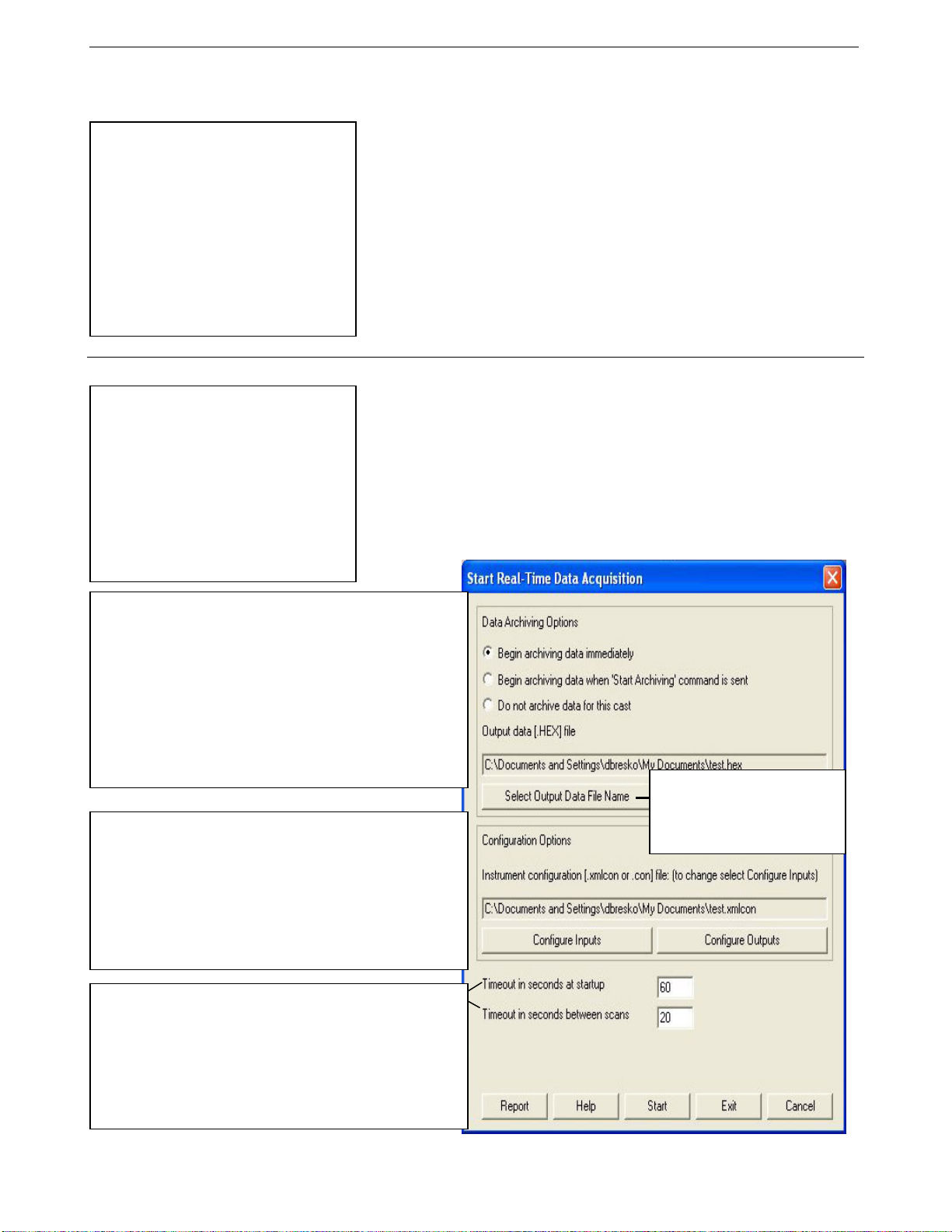
82
Section 4: Operating System SBE 45 Interface Box
Section 4: Operating System
Note:
For acquiring data in Seasave:
• SBE 45 must be set up for
autonomous sampling
(SingleSample=N, AutoRun=Y,
and J1 jumper in Autopower position
– pins 1 and 2), and with
OutputFormat=0 or 1. See Section
3: Setting Up System.
• Interface Box must be set up with
Format=0 (standard format) and
IMode=NORMAL (Normal mode).
This section covers acquiring real-time data with Seasave and processing data
with SBE Data Processing.
• Seasave saves the data in the format (data format and header) required by
SBE Data Processing. If you use other software to acquire data, the data
will not be in the format required by SBE Data Processing.
See Connections, Switches, and LEDs in Section 2: Interface Box Description
for wiring details.
Acquiring Real-Time Data with Seasave
Notes:
• If the system includes an SBE 38
remote temperature sensor,
Seasave uses the remote
temperature data when calculating
density and sound velocity.
• The baud between the Interface Box
and computer (defined in Configure
Inputs, on the serial Ports tab) must
agree with the baud programmed
into the Box with PCBaud=.
1. Turn on power to the Interface Box. The SBE 45 will start sampling and
transmitting data to the Interface Box. Data will not appear in Seasave
until you tell Seasave to start real-time data acquisition below.
2. Double click on Seasave.exe.
3. Perform any desired setup in the Configure Inputs, Configure Outputs,
and Display menus.
4. In the Real-Time Data menu, select Start. The dialog box looks like this:
Data Archiving Options:
• Begin archiving data immediately to store raw (frequencies,
A/D counts, and/or voltages) real-time data as soon as Start
button is clicked and communication is established.
• Begin archiving data when ‘Start Archiving’ command is
sent to control when data begins to be written to file. If you
make this selection, when you click Start button and
communication is established, a dialog box with Start Archiving
button appears. Click this button when ready to begin saving
scans to file, or select Start Archiving in Real-Time Data menu.
• Do not archive data for this cast to not save data to a file.
Real-time data will still appear in displays.
Configuration Options: Currently selected instrument
configuration (.xmlcon or .con) file is shown, containing information
on which parameters are output by SBE 45, SBE 45 data output
rate, and whether NMEA and SBE 38 data are appended to data
stream. To modify input configuration (.xmlcon or .con file, serial
port, water sampler, TCP/IP ports, and/or miscellaneous), click
Configure Inputs. To modify outputs (serial data output, shared file
output, mark variables, TCP/IP output, TCP/IP ports, SBE 14
remote display, PC alarms, header form and/or diagnostics), click
Configure Outputs.
• Timeout in seconds at startup: Time allowed before first data
scan is received from instrument. Seasave will time out and stop
attempting to acquire data if data is not received from instrument
within this time period.
• Timeout in seconds between scans: Maximum gap allowed
between scans after first data scan is received from instrument.
Seasave will time out and stop attempting to acquire data if data
is not received from instrument within this time period, Seasave
stops attempting to acquire data after this gap).
Click Select Output Data File
Name. Save Archived Data As
dialog box appears; browse to
desired file location, enter desired
file name, and click Save.
20
Page 86
Section 4: Operating System SBE 45 Interface Box
5. In the Start Real-Time Data Acquisition dialog box, click Start.
A. If you selected Begin archiving data immediately or Begin archiving
data when ‘Start Archiving’ command is sent above, and selected
Prompt for Header Information in the Header Form setup (Configure
Outputs), the Header Information dialog box appears. Fill in the
desired header and click OK.
B. If you selected Check Scan Length in the Options menu, Seasave
checks the configuration (.xmlcon or .con) file to verify that the scan
length defined by the configuration file matches the SBE 45 (i.e.,
number of outputs and inclusion of NMEA is as defined in the
configuration file). If a Scan length error appears, verify that:
• You are using the correct .xmlcon or .con file.
• The .xmlcon or .con file has been updated as necessary if you
added or deleted the SBE 38, added or deleted NMEA, etc.
C. Seasave sends a message: Waiting for data . . .. Seasave will time out if
data is not received within Timeout in seconds at startup.
D. Real-time data then starts appearing in the screen display(s).
6. To stop real-time data acquisition: In the Real-Time Data menu,
select Stop.
7. Stop the SBE 45 sampling by turning off power to the Interface Box.
83
Processing Data with SBE Data Processing
Note:
See the SBE Data Processing
manual and/or Help files.
1. Convert the .hex data file created by Seasave to a .cnv file in SBE Data
Processing’s Data Conversion module.
2. Once the data is converted, it can be further processed and plotted in
SBE Data Processing’s other modules. Note that if the data stream
includes SBE 38 remote temperature data, SBE Data Processing’s Data
Conversion and Derive modules use the remote temperature data when
calculating density and sound velocity.
21
Page 87

84
Section 5: Routine Maintenance SBE 45 Interface Box
Section 5: Routine Maintenance
To clean the Interface Box:
1. Disconnect the power and any other cables from the Interface Box.
2. Using a soft cotton cloth dampened with warm water, clean the exterior of
the Interface Box with gentle pressure. Use special care cleaning around
any connectors, to avoid getting water into them.
3. Wait until the Interface Box is completely dry before reconnecting power
cables and other electrical connections.
22
Page 88

Section 6: Troubleshooting SBE 45 Interface Box
Section 6: Troubleshooting
This section reviews common problems in operating the Interface Box, and
provides the most likely causes and solutions.
Problem 1: Unable to Communicate with Interface Box
The Interface Box message prompt indicates that communications between the
Interface Box and computer have been established. Before proceeding with
troubleshooting, attempt to establish communications again by clicking the
Connect button on SEATERM’s toolbar or hitting the Enter key several times.
Cause/Solution 1: The I/O cable connection may be loose. Check the cabling
between the Interface Box and computer for a loose connection.
Cause/Solution 2: The instrument type and/or its communication settings may
not have been entered correctly in SEATERM. Select SBE 45 in the Configure
menu and verify the settings in the Configuration Options dialog box. The
settings should match those on the instrument Configuration Sheet.
Cause/Solution 3: The I/O cable may not be the correct one. The I/O cable
supplied with the Interface Box permits connection to the DB-9P input
connectors used on standard RS-232 interfaces.
85
Problem 2: Unable to Communicate with SBE 45 through Interface Box
In SEATERM, while communicating with the Interface Box, send Connect45.
The following message should appear:
connected to SBE 45 . . .
This indicates that communications between the Interface Box and SBE 45
have been established. If this messages does not appear:
Cause/Solution 1: The cable connection may be loose. Check the cabling
between the SBE 45 and Interface Box for a loose connection.
Cause/Solution 2: The cable between the SBE 45 and Interface Box may not
be the correct one. Verify that the cable is the correct one.
Cause/Solution 3: The instrument type and/or its communication settings may
not have been entered correctly in SEATERM. Select SBE 45 in the Configure
menu and verify the settings in the Configuration Options dialog box. The
settings should match those on the instrument Configuration Sheet.
Cause/Solution 4: The baud rate for communication between the SBE 45 and
Interface Box may not match. The SBE 45’s baud rate (set with Baud= when
Note:
If applicable, see Problem 6:
Changing SBE 45 and/or SBE 38
Baud Rate without Cables for Direct
Connection below.
directly communicating with the SBE 45) must be the same as the baud rate
set in the Interface Box with 45Baud=.
Cause/Solution 5: The SBE 45 baud rate may be too high. The baud rate for
communication between the Interface Box and computer must be greater than
the baud rate between the Interface Box and SBE 45.
• Increase the Interface Box baud rate using PCBaud=. Or
• Connect the SBE 45 directly to the computer and decrease its baud rate
using Baud=. Then, with the Interface Box connected to the computer,
use 45Baud= to match the baud set in the SBE 45.
23
Page 89
86
Section 6: Troubleshooting SBE 45 Interface Box
Problem 3: Unable to Communicate with SBE 38 through Interface Box
In SEATERM, while communicating with the Interface Box, send Connect38.
The following message should appear:
connected to SBE 38 . . .
This indicates that communications between the Interface Box and SBE 38
have been established. If this messages does not appear:
Cause/Solution 1: The cable connection may be loose. Check the cabling
between the SBE 38 and Interface Box for a loose connection.
Cause/Solution 2: The cable between the SBE 38 and Interface Box may not
be the correct one. Verify that the cable is the correct one.
Cause/Solution 3: The baud rate for communication between the SBE 38 and
Interface Box may not match. The SBE 38’s baud rate (set with Baud= when
Note:
If applicable, see Problem 6:
Changing SBE 45 and/or SBE 38
Baud Rate without Cables for Direct
Connection below.
directly communicating with the SBE 38) must be the same as the baud rate
set in the Interface Box with 38Baud=.
Cause/Solution 4: The SBE 38 baud rate may be too high. The baud rate for
communication between the Interface Box and computer must be greater than
the baud rate between the Interface Box and SBE 38.
• Increase the Interface Box baud rate using PCBaud=. Or
• Connect the SBE 38 directly to the computer and decrease its baud rate
using Baud=. Then, with the Interface Box connected to the computer,
use 38Baud= to match the baud set in the SBE 38.
Problem 4: Unable to Communicate with NMEA Navigation Device through Interface Box
See Appendix I: NMEA Data for NMEA troubleshooting.
Problem 5: Nonsense or Unreasonable Data
The symptom of this problem is data that contains nonsense values (for
example, 9999.999) or unreasonable values (for example, values that are
outside the expected range of the data).
Cause/Solution 1: A data file with nonsense values may be caused by
incorrect instrument configuration in the .xmlcon or .con file. Verify the
settings in the configuration file match your system.
Cause/Solution 2: Unreasonable values may be caused by incorrect
calibration coefficients programmed into the instrument. Verify the calibration
coefficients in the SBE 45 and (optional) SBE 38 match the Calibration
Certificates. To verify calibration coefficients, use DC while communicating
with each instrument (either directly connected to the computer or through the
Interface Box) in SEATERM.
Cause/Solution 3: Unreasonable values may be caused by setting the
SBE 45’s output format to OutputFormat=2, which is incompatible with the
Interface Box. Verify that the SBE 45 is set to OutputFormat=0 or
OutputFormat=1 by sending DS while communicating with the SBE 45
(if the SBE 45 is set to OutputFormat=2, the last line of the DS response
shows conductivity and salinity order reversed).
24
Page 90

Section 6: Troubleshooting SBE 45 Interface Box
Problem 6: Changing SBE 45 and/or SBE 38 Baud Rate without Cables for Direct Connection
Note:
If you have a cable for direct
connection of the SBE 45 to the
computer and the SBE 38 to the
computer, see Setting Up
Instruments in Section 3: Setting Up
System to change the baud rates.
The baud rate for communication between the Interface Box and computer
must be greater than the baud rate between the Interface Box and SBE 45 and
baud rate between the Interface Box and the SBE 38. If you need to change the
baud rate in the SBE 45 and/or SBE 38 for compatibility with the Interface
Box, this procedure allows you to change the baud rate while the instrument is
communicating through the Interface Box. The procedure is written assuming
that the SBE 45 and SBE 38 are set to 9600 baud, but that you want the
computer to communicate with the Interface Box at 9600 baud.
In SEATERM:
1. Establish communications with the Interface Box, as described in Steps 1
through 4 in Communications Test and Setup in Section 3: Setting Up
System.
2. With the Interface Box in Normal mode, send PCBaud=19200
to change the baud rate between the Interface Box and the computer
to 19200.
3. In the Configure menu, select the SBE 45 and set the baud rate to 19200.
Turn power to the Interface Box off, and then on again. The Interface Box
is now communicating at 19200 baud.
4. To modify the SBE 45 baud rate:
A. Send 45Baud=9600 to set the baud rate in the Interface Box for
communication with the SBE 45 to 9600.
B. Send Connect45 to communicate with the SBE 45.
C. If the SBE 45 is sampling data, stop sampling by sending Stop (you
may need to send the command several times).
D. Send Baud=4800 to set the SBE 45 baud rate to 4800.
E. Type @ to return to Normal mode for communication with the
Interface Box.
F. Send 45Baud=4800 to set the baud rate in the Interface Box for
communication with the SBE 45 to 4800.
5. To modify the SBE 38 baud rate:
A. Send 38Baud=9600 to set the baud rate in the Interface Box for
communication with the SBE 38 to 9600.
B. Send Connect38 to communicate with the SBE 38.
C. If the SBE 38 is sampling data, stop sampling by sending Stop (you
may need to send the command several times).
D. Send Baud=4800 to set the SBE 38 baud rate to 4800.
Type @ to return to Normal mode for communication with the
E.
Interface Box.
F. Send 38Baud=4800 to set the baud rate in the Interface Box for
communication with the SBE 45 to 4800.
6. Send PCBaud=9600 to change the baud rate between the Interface Box
and the computer to 9600.
7. In the Configure menu, select the SBE 45 and set the baud rate to 9600.
Turn power to the Interface Box off, and then on again. The Interface Box
is now communicating with the computer at 9600 baud. If the SBE 45 and
SBE 38 are set up to begin sampling when power is applied, data will
appear.
87
25
Page 91
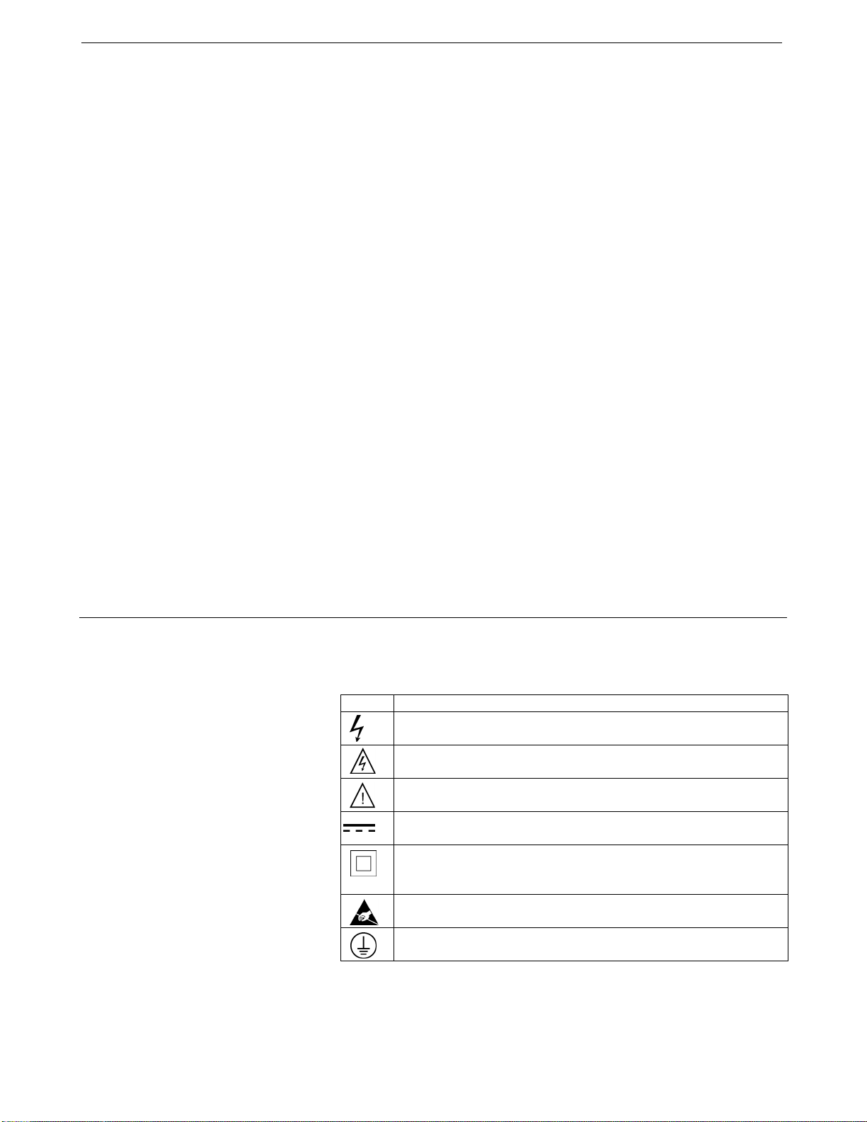
88
Glossary SBE 45 Interface Box
Glossary
NMEATest – Sea-Bird’s NMEA message simulation program, which
simulates NMEA messages for testing purposes. NMEATest is installed as
part of the SBE Data Processing installation.
PCB – Printed Circuit Board.
SBE 45 MicroTSG – High-accuracy conductivity and temperature monitor.
SBE Data Processing – Sea-Bird’s Win 2000/XP data processing
software, which calculates temperature and conductivity, as well as data from
auxiliary sensors, and derives variables such as salinity and sound velocity.
Scan – One data sample containing temperature and conductivity, as well as
data from auxiliary sensors.
Seasave V7 – Sea-Bird’s Win 2000/XP software used to acquire, convert,
and display real-time or archived raw data.
SEASOFT V2– Sea-Bird’s complete Win 2000/XP software package, which
includes software for communication, real-time data acquisition, data analysis
and display, and NMEA message simulation. SEASOFT V2 includes
SEATERM, Seasave, SBE Data Processing.
SEATERM – Sea-Bird’s Win 95/98/NT/2000/XP terminal program used to
communicate with the Interface Box and/or the SBE 45. SEATERM can send
commands to provide status display, data acquisition setup, data display and
capture, and diagnostic tests.
Safety and Electrical Symbols
Some or all of the following symbols may be used on the Interface Box:
Symbol Description
Potentially hazardous voltage.
Hazardous! Voltage > 30 VDC may be present.
Attention! There is a potential hazard; consult the manual before
continuing.
DC (Direct Current).
Double insulated. The metal enclosure of the Interface Box is
isolated such that protection from electrical shock is provided
through reinforced electrical insulation.
Static awareness. Static discharge can damage part(s).
Protective earthing terminal.
26
Page 92

Appendix I: NMEA Data SBE 45 Interface Box
Appendix I: NMEA Data
NMEA Raw Message Formats
The Interface Box can interpret NMEA data from a NMEA navigation device
if the data is in one of the following formats:
Notes:
• -- represents two device-specific
characters.
• See the table below for definitions
of message parameters.
• <CR> is carriage return.
• <LF> is line feed.
where
Field Type Symbol Definition
Status A
Latitude
Longitude
Time hhmmss.ss
Checksum
llll.ll
a N or S
yyyyy.yy
b E or W
* Optional Checksum Delimiter.
hh
Single character field:
A = Yes, data valid, warning flag clear V = No, data invalid, warning flag set
Fixed/Variable length field:
degrees|minutes.decimal - 2 fixed digits of degrees, 2 fixed digits of minutes, and variable
number of digits for decimal-fraction of minutes. Leading zeros always included for degrees and
minutes to maintain fixed length. Decimal point and associated decimal-fraction are optional if
full resolution not required.
Fixed/Variable length field:
degrees|minutes.decimal - 3 fixed digits of degrees, 2 fixed digits of minutes, and variable number
of digits for decimal-fraction of minutes. Leading zeros always included for degrees and minutes to
maintain fixed length. Decimal point and associated decimal - fraction optional if full resolution
not required.
Fixed/variable length field:
hours|minutes|seconds.decimal - 2 fixed digits of hours, 2 fixed digits of seconds, and variable
number of digits for decimal-fraction of seconds. Leading zeros always included for hours,
minutes, and seconds to maintain fixed length. Decimal point and associated decimal-fraction
optional if full resolution not required.
Optional Checksum Field:
Absolute value calculated by exclusive OR’ing 8 data bits (no start or stop bits) of each character
in message, between, but excluding $ and *.
GGA - Global Positioning System Fix Data
Time, position, and fix-related data for a GPS receiver.
$--GGA,hhmmss.ss,llll.ll,a,yyyyy.yy,b,x,xx,x.x,x.x,M,x.x,M,x.x,xxxx*hh<CR><LF>
GLL - Geographic Position - Latitude/Longitude
Latitude and Longitude of present position, time of position fix, and status.
$--GLL,llll.ll,a,yyyyy.yy,b,hhmmss.ss,A*hh<CR><LF>
RMA - Recommended Minimum Specific Loran-C Data
Position, course, and speed data provided by a LORAN-C receiver.
$--RMA,A,llll.ll,a,yyyyy.yy,b,x.x,x.x,x.x,x.x,x.x,a*hh<CR><LF>
RMC - Recommended Minimum Specific GPS/TRANSIT Data
Time, date, position, course, and speed data provided by a GPS or TRANSIT
navigation receiver.
$--RMC,hhmmss.ss,A,llll.ll,a,yyyyy.yy,b,x.x,x.x,ddmmyy,x.x,a*hh<CR><LF>
TRF - TRANSIT Fix Data
Time, date, position, and information related to a TRANSIT fix.
$--TRF,hhmmss.ss,ddmmyy,llll.ll,a,yyyyy.yy,b,x.x,x.x,x.x,x.x,xxx,A*hh<CR><LF>
89
27
Page 93

90
Appendix I: NMEA Data SBE 45 Interface Box
Troubleshooting NMEA
Problem 1: Yellow NMEA LED Not Flashing
Cause/Solution 1: Wiring may be incorrect. Check cables and connections
between the Interface Box, NMEA navigation device, and computer.
Cause/Solution 2: NMEA navigation device may be set to the wrong
communication parameters (Interface Box requires 4800 or 9600 baud, 8 data
bits, 1 stop bit, and no parity). Reset device’s communication parameters.
Verify that the baud rate in the Interface Box for communication with the
NMEA navigation device is set to match (NMEABaud=), and that the baud
rate is less than the baud rate for communication between the Interface Box
and the computer.
Cause/Solution 3: NMEA navigation device may not be transmitting data. See
the device manual for setup details. To verify that it is sending data, connect
an oscilloscope with ground on NMEA B (T17) and the probe on NMEA A
(T16). The signal should be less than 0.5 volts between messages and have
pulses greater than 4 volts for at least 0.2 milliseconds during the message.
Cause/Solution 4: Interface Box may not be operating properly. To verify, use
the simulation program supplied with SEASOFT V2. This program simulates
a NMEA navigation device transmitting a NMEA message. See NMEA
Message Simulation Program for details.
Problem 2: Yellow NMEA LED Flashing, but Lat/Lon Data Not Displaying
Cause/Solution 1: NMEA navigation device may be transmitting NMEA
messages in a format that cannot be interpreted by the Interface Box. To
verify, view the raw NMEA messages:
1. With the Interface Box running in Normal mode, type ConnectNMEA
and press the Enter key to switch to NMEA mode. The display looks
like this:
Decode NMEA messages, press @ or Esc to return to normal mode
2. The raw NMEA data should begin scrolling on the screen, followed by
the decoded data. A typical RMC NMEA message is:
NMEA: $LGRMC,123113.21,A,3625.12,N,12121.34,W,1.2,4.5,231294,1.2,a*45<CR><LF>
Decoded: , lat=36 25.12 N, lon=121 21.34 W, hms=123113, dmy=231294
See NMEA Raw Message Formats for a description of all the NMEA
messages the Interface Box can decode.
• If a different NMEA message is received than the Interface Box is
set up to decode, reconfigure your NMEA navigation device to
transmit GGA, GLL, RMA, RMC, or TRF.
• If no NMEA messages are received in NMEA mode, the problem
could be in the Interface Box, cable, or NMEA navigation device.
Verify that the Interface Box is operating properly using the
simulation program supplied with SEASOFT V2. This program
simulates a NMEA navigation device transmitting a NMEA message.
See NMEA Message Simulation Program for details.
3. Type @ to return to Normal mode.
28
Page 94
Appendix I: NMEA Data SBE 45 Interface Box
NMEA Simulation Program
Sea-Bird provides a NMEA message simulation program, NMEATest, as a
troubleshooting aid. NMEATest, part of the SEASOFT V2 package, simulates
a NMEA navigation device transmitting NMEA messages. If the system does
not work with the NMEA navigation device, but works with NMEATest, the
problem is with the interface cable from the NMEA navigation device to the
Interface Box or in the NMEA navigation device itself.
NMEATest is just a simulation, and does not provide an actual data stream
from an actual NMEA navigation device. The data transmission baud rate
(4800 or 9600) and time between messages are user-programmable. The
NMEA message format (RMA, RMC, GLL, or GGA) generated by the
program is also user-programmable. Alternatively, the user can specify an
existing raw NMEA data file to use for the simulation; see NMEA Raw
Message Formats for the required raw data format.
Note:
You can also run the simulation
using only one computer, if the
computer has a spare COM port.
Note:
The Interface Box must be
connected to the SBE 45 to test the
Box, because the Box only
transmits a scan of data when data
is received from the SBE 45.
To execute the simulation program, a second computer (computer 2) is
needed to emulate the NMEA navigation device. A laptop computer is
adequate for this purpose. Install NMEATest on computer 2 (NMEATest is
part of the SBE Data Processing installation).
Use the NMEA Interface test cable (PN 801422 - supplied with the Interface
Box) to connect the Interface Box to the simulation computer. The simulation
test cable connections are:
MS-3106A12S-3S DB-9S Function
Pin A Pin 3 NMEA A (signal)
Pin B Pin 5 NMEA B (signal return)
Proceed as follows (instructions are written assuming you are using a second
computer to emulate the NMEA navigation device):
1. On computer 1, double click on Seaterm.exe.
2. Turn on power to the Interface Box. SEATERM displays:
SBE 45 Junction Box V 1.4
Data from the SBE 45 should begin scrolling on the screen.
3. On computer 2, double click on nmeatest.exe (in same directory as SBE
Data Processing). The NMEATest screen appears.
4. On the NMEATest screen, click on the Configure menu. The Configure
dialog box appears. Select:
• NMEA message to be simulated (RMA, RMC, GLL, or GGA) or
select an existing NMEA data file on your computer by clicking Send
File and browsing to the desired file
• Baud rate (4800 or 9600) for transmission of simulated NMEA data
to Interface Box – must be less than baud rate between Interface
Box and computer 1
• COMM port on computer 2 for transmission of NMEA data to
Interface Box
• Message interval (time between simulated messages to be transmitted
to Interface Box)
Click OK.
91
29
Page 95

92
Appendix I: NMEA Data SBE 45 Interface Box
5. On the NMEATest screen, click Start. NMEA data should begin to display
on the NMEATest screen. Additionally, NMEA data should begin to
display appended to the SBE 45 data in SEATERM on computer 1. The
yellow NMEA LED should flash on the Interface Box each time the
simulation program transmits a new position. The appended data should
correspond to the most recent simulation program data. For example, if
NMEATest is set to output RMC data:
NMEATest output -
RMC: 2212.345,N, 04459.876,E, 15 May 2002 00:00:22
SEATERM output (appended after SBE 45 data and optional SBE 38 data) -
lat=22 12.345 N, lon=044 59.877 E, hms=000022, dmy=150502
See NMEA Raw Message Formats for the NMEA message formats.
If properly decoded data appears in SEATERM, the Interface Box is working
properly. If the system works with the simulation program but does not work
when connected to the actual NMEA navigation device, the problem is with
the cable from the NMEA navigation device to the Interface Box, or in the
NMEA navigation device itself.
• Verify that the cable pinouts are correct, especially at the NMEA
navigation device. See Connections, Switches, and LEDs in Section 2:
Interface Box Description and also refer to the NMEA navigation device
documentation.
• If the cable is correct, verify that the NMEA navigation device is on and is
configured to send data. Many NMEA navigation devices have
programmable NMEA outputs and may need to be configured before they
will transmit NMEA messages. Refer to the NMEA navigation device
documentation, or contact the device’s manufacturer for customer support.
30
Page 96

Appendix II: Replacement Parts SBE 45 Interface Box
Appendix II: Replacement Parts
Part
Number
171887
171888
801216
80437 or
80438
801422
17015
17315
17316 MS3057-4A clamp Assembled to 17315 1
17317 MS-3420-4 boot Assembled to 17315 1
17412 MS-3106A-14S-2P
17413 Clamp Assembled to 17412 2
17414 Boot Assembled to 17412 2
17671 MS-3106A-12S-3S
17413 Clamp Assembled to 17671 1
17414 Boot Assembled to 17671 1
DB-9P to DB-9S cable,
3 m (10 ft)
25-pin DB-25S to
9-pin DB-9P
cable adapter
4-pin MCIL-4MP to
4-pin MS3106A-14S-2P
cable, 2.5 m (8 ft ) long
4-pin RMG-4FS to
4-pin MS-3106A-14S-2P:
80437 – 2.5 m (8 ft)
80438 – 10 m (33 ft)
2-pin MS-3106A-12S-3S to
9-pin DB-9S NMEA
Interface test cable,
1.8 m (6 ft)
Interface Box AC power
cable
MS-3106A12S-3S
connector
Part
Application
Description
From Interface Box to
computer
For use with computer
with DB-25 connector
From SBE 45 to
Interface Box
From SBE 38 to
Interface Box
From NMEA on
Interface Box to
computer running
NMEA simulation
program for test
purposes
Connect Interface Box
to AC power source
2-pin NMEA
connector to
Interface Box
4-pin SBE 45 and
SBE 38 connector to
Interface Box
2-pin NMEA
connector
Quantity
1
-
1
1
1
1
1
2
1
93
31
Page 97

94
Index SBE 45 Interface Box
Index
raw message formats · 27
.
.con file · 19
.xmlcon file · 19
B
Baud rate · 7
C
Cleaning · 22
Commands
baud rate · 14
diagnostic · 16
mode · 15
output format · 16
sampling · 16
status · 14
Communications · 7, 12
Configuration file · 19
Connections · 8
simulation program · 29
troubleshooting · 28
NMEATest · 6, 10, 29
O
Operating system · 20
P
Parts
replacement · 31
Power-up
mode · 15
Processing data · 21
R
Real-time acquisition · 20
Replacement parts · 31
Routine maintenance · 22
D
Data acquisition · 20
Data format · 9
Data processing · 21
Description · 6
E
Electrical symbols · 26
F
Format · 9
G
Glossary · 26
I
Installing software · 10
Instrument setup · 17
L
LEDs · 8
S
Safety symbols · 26
SBE 38 · 17
baud rate · 14, 17
mode · 15, 17
setup · 17
SBE 45 · 17
baud rate · 14, 17
mode · 15, 17
setup · 17
SBE Data Processing · 6, 10, 19, 21
Seasave · 6, 10, 19, 20
SEASOFT · 6, 10
SEATERM · 6, 10
Setting up instruments · 17
Setup · 11
Simulation program · 29
Software · 6, 10
Specifications · 7
System
communications · 7
description · 6
operation · 20
wiring · 8
T
Testing · 11
Troubleshooting · 28
M
Maintenance · 22
N
NMEA · 18
baud rate · 14, 18
mode · 15, 18
U
Unpacking · 5
W
Wiring · 8
32
Page 98

CALIBRATION SHEETS
SBE 45 Temperature Calibration - S/N 0402.................................................................................................................................................................................................................
1
SBE 45 Conductivity Calibration - S/N 0402................................................................................................................................................................................................................
2
95
Page 99
Residual, (Degrees C)
96
SENSO
CALIBRA
ITS-90
a0 = 5
a1 = 2
a2 = -1
a3 = 1
BATH T
(ITS
1.00
4.50
15.00
18.50
24.00
29.00
32.50
Tempera
R
C
13431
Phone:
SERIAL NUM
TION DATE:
OEFFICIENTS
.724520e-00
.658577e-00
.827700e-00
.335867e-00
EMP
90)
-
00
00
00
00
00
01
01
ure ITS-90 = 1/{a
t
+1) 425-643-9
(
Sea
NE 20th
ER: 040
B
1-Jan-1
3
5
4
6
7
INSTRUME
OUTPUT
744013.
634618.
401693.
347069.
277505.
227834.
199120.
0 + a1[
2
2
(n)] + a2
l
n
Bird El
-
treet, Bellev
S
66 Fax (+1) 425
8
T
N
0
6
2
1
6
0
0
2
[
(n)] + a3
l
n
ctronic
e
ue, WA 98
-643-9954 Ema
SBE 45
ITS-90
[
l
n
T
EMPERATURE
T
INST TEMP
(ITS-90)
1.0000
4.5000
15.0000
18.5000
24.0000
29.0001
32.5001
3
(n)]} - 2
, Inc
s
005-2010
il: seabird@sea
EMPERATUR
0
-0
0
-0
-0
-0
0
3.15
(
7
°C)
.
U
bird.co
CALIBRATIO
E
SCALE
R
(
S
A
m
DATA
N
ESIDUAL
ITS-90)
.0000
.0000
.0000
.0000
.0000
.0000
.0000
0.02
0.01
0.00
-0.01
Residual
= instrument temp
erature - bath te
peratur
m
e
Date, Del
31-Jan-12 0.00
ta T (mdeg C)
-0.02
-5 0 5 10 15 20 25 30 35
Temperature, Degrees C
Page 100
Residual, (S/m)
97
SENSO
CALIBRA
COEFFIC
g = -9.
h = 1.
i = -4.
j = 5.
BATH T
(ITS
22.00
1.00
4.50
15.00
18.50
24.00
29.00
32.50
f = INST
Conductiv
t = tempe
R
13431
Phone:
SERIAL NUM
TION DATE:
IENTS
795662e-001
448786e-001
310804e-004
434011e-005
EMP BATH
90) (PS
-
00 0.00
00 34.70
00 34.68
00 34.64
00 34.63
00 34.62
01 34.62
01 34.62
FREQ * sqrt(1.0
ity = (g + hf
rature[
(
:
2
°C)]; p = pre
Sea
NE 20th
+1) 425-643-9
ER: 040
B
1-Jan-1
3
SAL BATH C
) (Siemens/
U
00 0.000
95 2.967
93 3.273
65 4.252
76 4.597
79 5.153
28 5.674
05 6.045
+ WBOTC * t) /
+ if3 + jf4) / (1 + δt + εp) Sieme
ssure[decibars];
Bird El
-
treet, Bellev
S
66 Fax (+1) 425
8
2
2
O
N
D
INST FRE
m) (Hz)
0 2607.0
0
0 5233.6
7
2 5432.2
9
8 6022.8
9
1 6216.8
2
9 6517.9
6
9 6787.0
1
1 6972.5
7
1000.
0
δ = CTcor
ctronic
e
ue, WA 98
-643-9954 Ema
SBE 45
PSS 197
CPcor =
CTcor =
WBOTC =
s/meter
n
; ε = CPcor
C
8
Q INST CO
(Siemens/
4 0.0000
0 2.9677
8 3.2739
5 4.2529
5 4.5972
1 5.1536
8 5.6742
9 6.0457
;
, Inc
s
005-2010
il: seabird@sea
ONDUCTIVITY
: C(35,15,0) = 4.
-9.5700e-0
3.2500e-0
1.5981e-0
D RESID
N
m) (Siemens
0.000
0
-0.000
0
0.000
3
0.000
9
0.000
2
-0.000
7
0.000
1
-0.000
0
.
S
U
bird.co
CALIBRATIO
914 Siemens/m
2
0
8
0
6
0
7
A
U
/m)
0
0
0
0
0
0
0
0
A
m
DATA
N
ter
e
L
0
1
1
1
0
2
2
1
Residual
0.002
0.001
0.000
-0.001
= instrument cond
uctivity - bath c
nductivit
o
y
Date, Slo
31-Jan-12 1.0000000
pe Correction
-0.002
0 1 2 3 4 5 6 7
Conductivity (Siemens/m)
 Loading...