

Page 1

801 Avenida Acaso, Camarillo, Ca. 93012 • (805) 494-0622 •
www.sdcsecurity.com • E-mail: [email protected]
INSTALLATION INSTRUCTIONS IP100HK (Hager)
ELECTRIC LATCH RETRACTION DEVICE KIT
MODELS: 4501-RIM & 4501-SVR
ELECTRICAL DATA
12VDC @ 700/110mA
RED (+) BLK (-)
PATENT #8,851,530
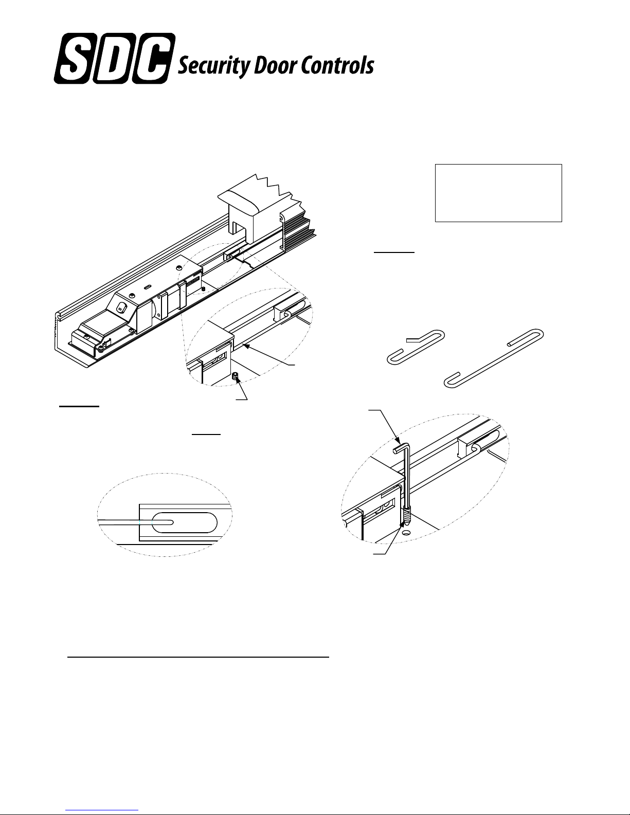
Step 1
Slide the Electric Latch Retraction
assembly into device and attach
the linkage to the latch retraction
rod (short linkage for standard,
long linkage for 4' device).
Short
Step 2
SET SCREW
Carefully slide the assembly
back out until the linkage JUST
IP100 LINKAGE
TIGHTEN SET
SCREWS TO
LOCK DEVICE
IN POSITION
Long
makes contact with the latch
retraction rod. Tighten set
screws.
SET
SCREWS
Retrofit Installation Note:
42" or 48" exit devices that have been modified to fit a 36" or
smaller opening, may not have the required space to fit the standard E. L. R. assembly. Always
verify the distance from the end of the touchpad to the end rail, and if necessary, consult with the
factory for appropriate selection.
NOTE Retro-Fitting Vertical Rod Devices:
Before retro-fitting an electric latch assembly into a vertical device, the following must be done
to ensure proper alignment. Disconnect the vertical rods from the device. Install the electric
latch assembly as shown above. Once the ELR is properly installed energize it so that the
push pad is dogged down, by doing so it will allow for proper alignment for the vertical rods.
Finally reconnect the vertical rods to the device and make the proper adjusments.
Any suggestions or comments to this instruction or
P:\INSTALLATION INST\SWITCH KITS\INST-IP100HK.vsd REV - 09-15 Page 1
product are welcome. Please contact us through
our website or email engineer@sdcsec urity.com
Page 2
801 Avenida Acaso, Camarillo, Ca. 93012 • (805) 494-0622 •
www.sdcsecurity.com • E-mail: [email protected]
INSTALLATION INSTRUCTIONS IP100HK (Hager)
ELECTRIC LATCH RETRACTION DEVICE KIT
MODELS: 4501-RIM & 4501-SVR
ELECTRICAL DATA
12VDC @ 700/110mA
RED (+) BLK (-)
PATENT #8,851,530
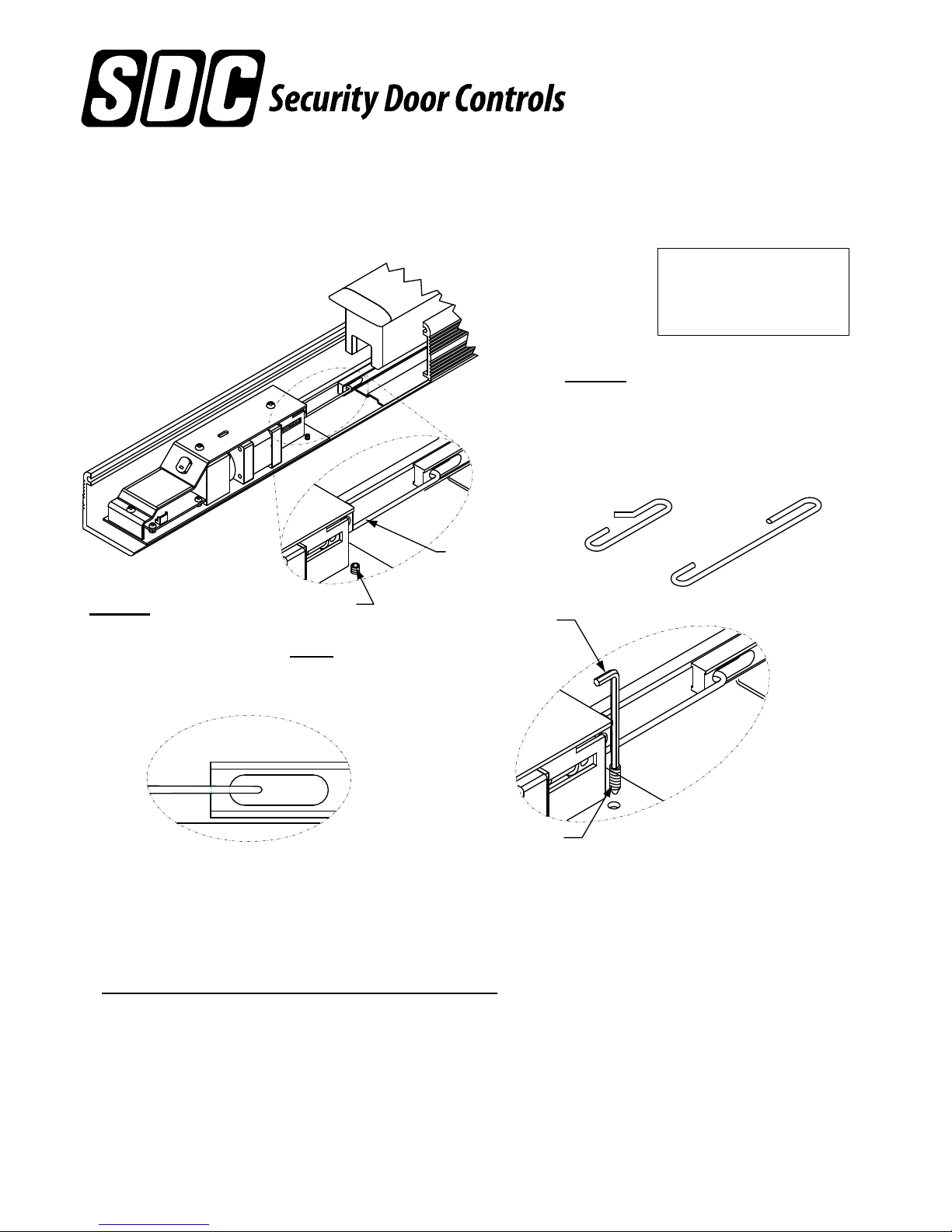
Step 1
Slide the Electric Latch Retraction
assembly into device and attach
the linkage to the latch retraction
rod (short linkage for standard,
long linkage for 4' device).
Short
Step 2
SET SCREW
Carefully slide the assembly
back out until the linkage JUST
IP100 LINKAGE
TIGHTEN SET
SCREWS TO
LOCK DEVICE
IN POSITION
Long
makes contact with the latch
retraction rod. Tighten set
screws.
SET
SCREWS
Retrofit Installation Note:
42" or 48" exit devices that have been modified to fit a 36" or
smaller opening, may not have the required space to fit the standard E. L. R. assembly. Always
verify the distance from the end of the touchpad to the end rail, and if necessary, consult with the
factory for appropriate selection.
NOTE Retro-Fitting Vertical Rod Devices:
Before retro-fitting an electric latch assembly into a vertical device, the following must be done
to ensure proper alignment. Disconnect the vertical rods from the device. Install the electric
latch assembly as shown above. Once the ELR is properly installed energize it so that the
push pad is dogged down, by doing so it will allow for proper alignment for the vertical rods.
Finally reconnect the vertical rods to the device and make the proper adjusments.
Any suggestions or comments to this instruction or
P:\INSTALLATION INST\SWITCH KITS\INST-IP100HK.vsd REV - 09-15 Page 1
product are welcome. Please contact us through
our website or email engineer@sdcsec urity.com
Page 3
801 Avenida Acaso, Camarillo, Ca. 93012 • (805) 494-0622 •
www.sdcsecurity.com • E-mail: [email protected]
INSTALLATION INSTRUCTIONS IP100HK (Hager)
ELECTRIC LATCH RETRACTION DEVICE KIT
MODELS: 4501-RIM & 4501-SVR
ELECTRICAL DATA
12VDC @ 700/110mA
RED (+) BLK (-)
PATENT #8,851,530
Step 1
Slide the Electric Latch Retraction
assembly into device and attach
the linkage to the latch retraction
rod (short linkage for standard,
long linkage for 4' device).
Short
Step 2
SET SCREW
Carefully slide the assembly
back out until the linkage JUST
IP100 LINKAGE
TIGHTEN SET
SCREWS TO
LOCK DEVICE
IN POSITION
Long
makes contact with the latch
retraction rod. Tighten set
screws.
SET
SCREWS
Retrofit Installation Note:
42" or 48" exit devices that have been modified to fit a 36" or
smaller opening, may not have the required space to fit the standard E. L. R. assembly. Always
verify the distance from the end of the touchpad to the end rail, and if necessary, consult with the
factory for appropriate selection.
NOTE Retro-Fitting Vertical Rod Devices:
Before retro-fitting an electric latch assembly into a vertical device, the following must be done
to ensure proper alignment. Disconnect the vertical rods from the device. Install the electric
latch assembly as shown above. Once the ELR is properly installed energize it so that the
push pad is dogged down, by doing so it will allow for proper alignment for the vertical rods.
Finally reconnect the vertical rods to the device and make the proper adjusments.
Any suggestions or comments to this instruction or
P:\INSTALLATION INST\SWITCH KITS\INST-IP100HK.vsd REV - 09-15 Page 1
product are welcome. Please contact us through
our website or email engineer@sdcsec urity.com
 Loading...