

Page 1
801 Avenida Acaso, Camarillo, Ca. 93012 • (805) 494-0622 •
www.sdcsecurity.com • E-mail: [email protected]
INSTALLATION INSTRUCTIONS
55 SERIES ELECTRIC STRIKE
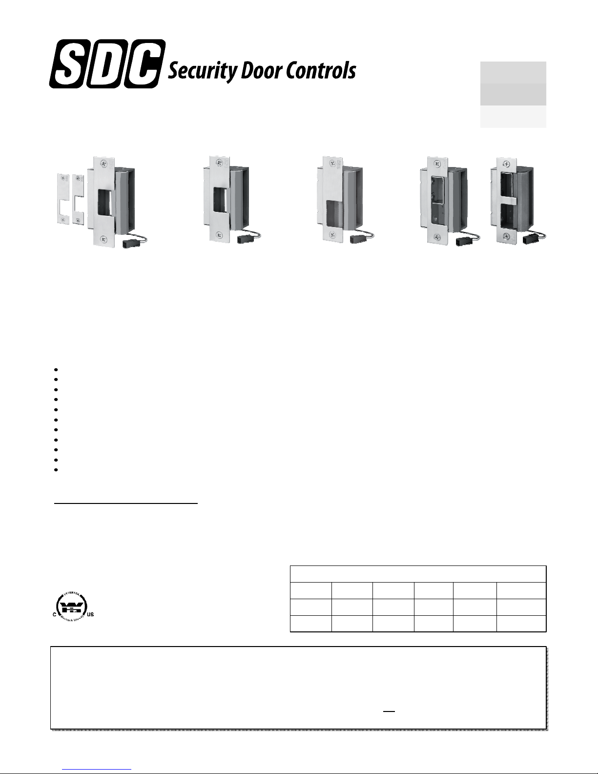
55-ABC Universal Strike Pak for
multiple cylindrical and mortise
lockset applications.
55-A for cylindrical locksets
With 1/2" to 3/4" latch.
SDC 55 Series heavy duty electric strikes are designed
for use with cylindrical and mortise locksets and mortise
exit devices. Several faceplate configurations eliminate
the need for centerline relocation, making them perfect
for new or retrofit construction.
FEATURES:
Non-handed
No Centerline relocation
Up to 3/4” latch and 1” deadbolt
1/8”Horizontal alignment adjustment
Field selectable Fail-Safe/Fail-Secure
Field selectable 12/24VDC
Stainless steel, corrosion resistant
Tamper resistant heavy duty construction
Plug-in connector
Fits ANSI 115.1 frame prep. with face modification
Patent pending
OPTIONAL MONITORING OUTPUTS:
LCM (Keeper Deadlocked Monitor)
Signals keeper is closed and deadlocked and/or unlocked.
LBM (Latch Bolt Monitor)
Signals latch is extended into strike and/or retracted.
DBM (Deadbolt Monitor)
Signals deadbolt is extended into strike and /or retracted.
55-B / 55-C For mortise
locksets with up to a 3/4" latch
55-D / 55-E / 55-F for mortise
locksets with latch and deadbolt
INSTALLATION
1. Verify lock compatibility, refer to page 2 and Fig. 6, page 4.
2. For proper frame preparation, refer to template drawings,
Fig. 4 & 5, page 4.
2. Factory supplied in Failsecure mode. For Failsafe mode refer
to Fig. 2, page 3
3. Determine minimum wire gauge required. See wire gauge chart below.
4. CAUTION! Before connecting power wires check for proper operating
voltage at opening with a volt meter. Voltage must be within +/- 10%
of strike operating voltage for proper operation.
5. Configure strike for 12 or 24VDC operation. Refer to pigtail power
connector wiring in Fig. 1, Page 3. Connect wires to power source.
6. To install the strike into the frame opening:
A) Position the wiring either down or up or toward the back of the
hollow metal frame. Make sure wires are completely clear of strike,
so they are not pinched when mounting strike in the frame.
B) Insert mounting screws through the faceplate and secure into
mounting tabs.
7. After installation check horizontal alignment. There should be 1/32”
allowable movement when the door is pulled toward the keeper.
8. ALIGNMENT ADJUSTMENT: Loosen mounting screws, shift strike
body behind faceplate horizontally as shown in Fig. 3A, page 3,
then tighten mounting screws.
9. For excessive horizontal alignment issues, remove shim filer bar from
the keeper as shown in Fig. 3B, page 3
10. The Electric Door Strike MUST be installed in such a way and in such a
location so as not to impair the operation of an emergency exit or panic
hardware mounted on the door.
Strike Input - Minimum Wire Gauge Requirements
Warnock Hersey Tested according to:
UL 10C, 3 Hr Fire Rated (Fail-Secure only).
UL Tested according to:
UL 1034 Burglary-Resistant
OPERATION:
Fail-Secure (Power-to-Unlock): Unlocked when energized.
Locked when de-energized and during power failure.
Application: For non fire rated and fire rated doors (exception,
may not be used on stairwell doors). May not be maintained in
the unlocked (energized) state when used with fire rated doors.
P:\INSTALLATION INST\ELECTRIC STRIKES\INST-55\INST-55.vsd REV D 10-12 Page 1
Voltage 100 ft 150 ft 200 ft 250 ft 300 ft
12VDC 18 Ga 16 Ga 14 Ga 14 Ga ---
24VDC 18 Ga 18 Ga 18 Ga 16 Ga 16 Ga
Monitoring outputs: Minimum 22 Gage wire recommended
Fail-Safe (Power-to-Lock): Locked when energized. Unlocked
when de-energized and during power failure.
Application: Non-fire rated doors only.
CAUTION: Fail-safe is not permitted with the UL Fire Door
Accessory label.
Page 2
55 SERIES ELECTRIC STRIKE
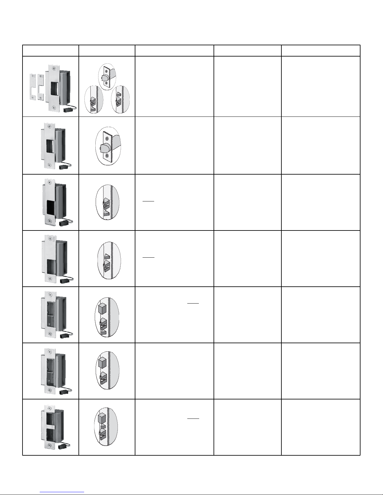
Strike body and faceplate(s) provided as shown below.
Faceplates are interchangeable and may be ordered separately.
UNIVERSAL APPLICATION KITS
Order strike bodies and different faceplates separately
to accommodate all applications.
Model Lockset Application Compatible Locks Operation
55-ABC
55-A
55-B
55-C
Universal Strike Pak
• Adaptable to all 55-A, 55-B, 55C
applications listed below.
• 5 strike body and faceplates
• For new and retrofit installation
• No relocation of the centerline.
• Bored (Cylindrical) locks.
• No relocation of the centerline.
• Mortise locksets and exit devices
with or without a deadlatch located
below the latchbolt.
• For new and retrofit installation
• No relocation of the centerline.
• Mortise locksets and exit devices
with or without a deadlatch located
above the latchbolt.
• For new and retrofit installation
• No relocation of the centerline.
• All cylindrical locksets
with .5" or .625" latchbolts.
See 55-A
• All mortise locksets listed
with 55-B & 55-C
• All cylindrical locksets
with .5" or .625" latchbolts
• Adams Rite 4720 ANSI and
compatible narrow stile locks.
• Accurate
• Arrow
• Best
• Corbin Russwin
• Falcon
• Marks
• Sargent
• Yale
• Dorma
• SDC
• Baldwin
• Hager
• Schlage
After releasing the latchbolt, the
keeper returns to the locked position.
After releasing the latchbolt, the
keeper returns to the locked
position.
After releasing the latchbolt, the
keeper returns to the locked position.
After releasing the latchbolt, the
keeper returns to the locked position.
55-D
• Mortise locksets with a deadbolt
and a deadlatch located below
the latchbolt.
• Deadbolt will not release.
• For new and retrofit installation
• No relocation of the centerline.
55-E
• Mortise lockset with a deadbolt.
• Deadbolt will not release.
• For new and retrofit installation
• No relocation of the centerline.
55-F
• Mortise locksets with a deadbolt
and a deadlatch located above
the latchbolt.
• For new and retrofit installation
• Deadbolt will not release.
P:\INSTALLATION INST\ELECTRIC STRIKES\INST-55\INST-55.vsd REV D 10-12 Page 2
• Accurate
• Arrow
• Best
• Corbin Russwin
• Dorma
• Baldwin
• SDC
• Schlage
• Hager
• Falcon
• Marks
• Sargent
• Yale
When the deadbolt is projected
manually, the strike will not release.
When the deadbolt is retracted,
access is accomplished by
electrically releasing the keeper.
When the deadbolt is projected
manually, the strike will not release.
When the deadbolt is retracted,
access is accomplished by
electrically releasing the keeper.
When the deadbolt is projected
manually, the strike will not release.
When the deadbolt is retracted,
access is accomplished by
electrically releasing the keeper.
Page 3
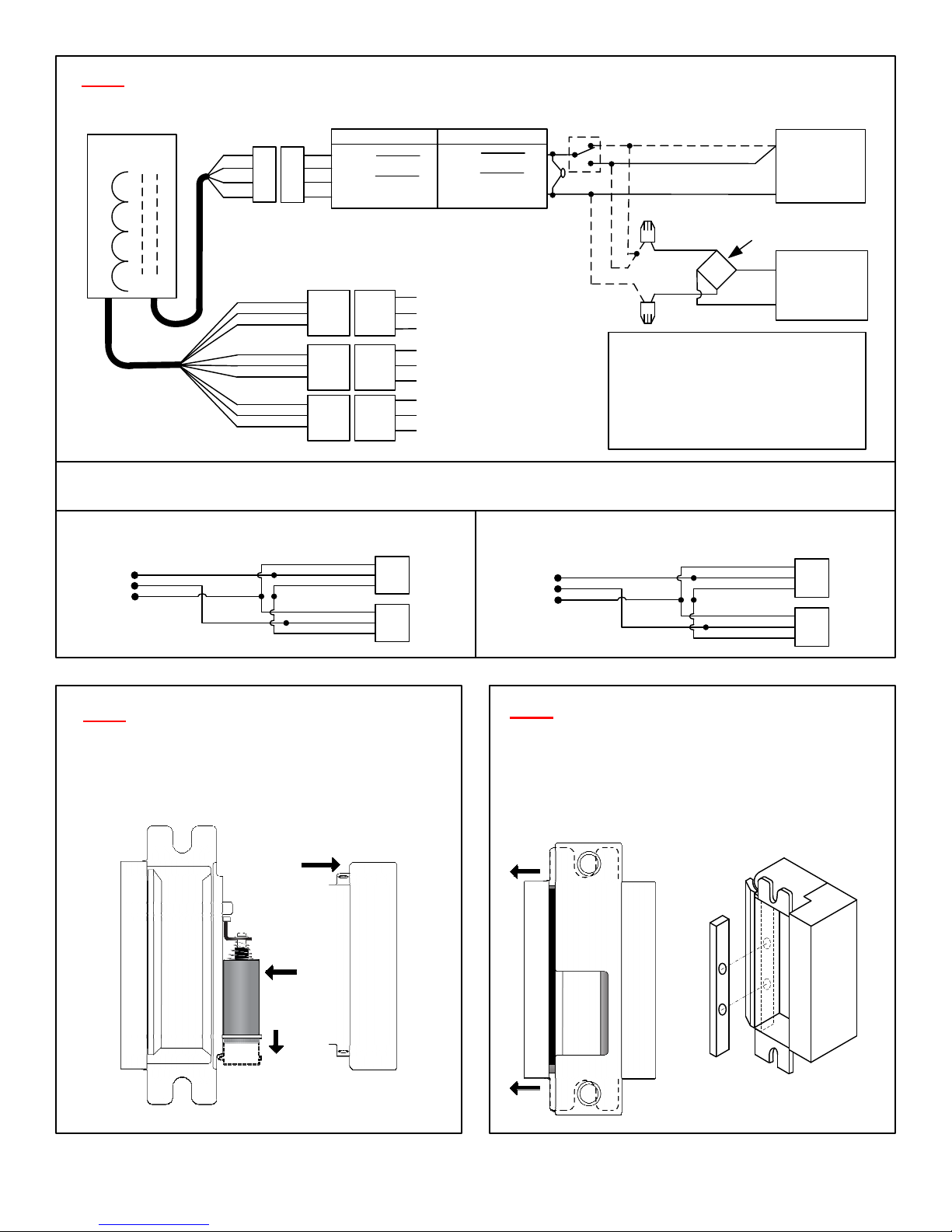
FIG. 1
WIRE DIAGRAM - 55 SERIES ELECTRIC STRIKE
ACCESS
CONTROL
+
_
MOV
*
*
Fail-Safe
+
Fail-Secure
-
AC to DC Rectifier
+ RED
- WHT
Strike Input: Dual Voltage
Contacts: SPDT, Dry, 5 Amp @ 30V
NOTE: LCM Contacts Reversed
*
SDC BR64XL
+
YEL
~
YEL
~
~
~
-
600 mA @ 12VDC
300 mA @ 24VDC
When in Failsafe Mode
STRIKE
Power
Connector
ORG/BLK
WHT/BLK
YEL/BLK
ORG
WHT
YEL
ORG/RED
WHT/RED
YEL/RED
SDC 12/24V Pigtail P/N CA-55-4
12V/600mA 24V/300mA
Red
Red
Black
Cable 1
NOTE: Power wires must not be connected
to supply wires larger than 18AWG
+
_
White
Cable 2
Monitoring
Connectors
LCM
LBM
DBM
N/C (Powered = Open)
COM
N/O (Powered = Closed)
N/C (Latched = Open)
COM
N/O (Latched = Closed)
N/C (Bolt Thrown = Open)
COM
N/O (Bolt Thrown = Closed)
HIGH SECURITY DOOR SECURE MONITORING: LCM & LBM Required
LCM & LBM wired in series indicates door is closed, latched and strike is deadlocked or door is open or unlocked
FAIL SECURE MODE – Door Secure or Unlocked Status
COM
N/O
N/C
YEL/BLK
WHT/BLK
ORG/BLK
ORG
WHT
YEL
LCM
LMB
FAIL SAFE MODE – Door Secure or Unlocked Status
ORG/BLK
COM
N/O
N/C
WHT/BLK
YEL/BLK
ORG
WHT
YEL
12 or 24V
DC
Power Supply
12 or 24V
AC
Transformer
LCM
LMB
FIG. 2 FIELD REVERSIBLE
FAILSAFE / FAILSECURE
Failsecure Mode: Factory supplied, Failsecure
Failsafe Mode: Remove cover, push solenoid toward
end of strike as shown below.
Remove Cover
Failsecure
Shown
Failsafe
P:\INSTALLATION INST\ELECTRIC STRIKES\INST-55\INST-55.vsd REV D 10-12 Page 3
FIG. 3 HORIZONTAL ALIGNMENT ADJUSTMENT
3A-Nominal Alignment: Loosen mounting screws.
Shift strike body behind the faceplate horizontally.
Tighten mounting screws.
3B-Excessive Alignment Issues:
Remove shim filler bar from keeper.
3A 3B
Page 4
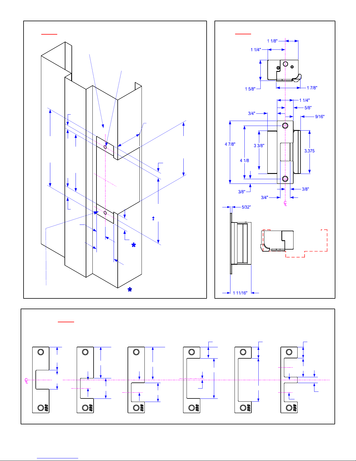
FIG. 4 FRAME PREPARATION – 55 Electric Strike
CENTER LINE OF STRIKE AND LOCK,
AND LOCK BOLT SHOULD ALIGN HORIZONTALLY
2X TAP FOR #12-24 UNC THDS THRU
.250
4.875
(4-7/8”)
+.015
-.000
(1/4”)
3.625
(3-5/8”)
+.015
-.000
C
L
C
L
1.688
(1-11/16”)
.375
(3/8”)
FIG. 5 STRIKE DIMENSIONS
3.375
(3-3/8”)
+.015
-.000
.625
5/8”
4.125
(4-1/8”)
.005
.625
5/8”
.734
1.250
1-1/4”
+.015
-.000
2X 5/32” MTG TAB DEPTH (TYP)
47/64” STANDARD ANSI
FIG. 6 FACE PLATES – All faceplates are interchangeable for application requirements
55-A 55-B 55-C 55-D 55-E 55-F
1-3/4"
2-5/16”
2-5/8"
7/8"
2-31/32"
7/8"
7/8"
2 x 1-3/8"
1- 3/8"
P:\INSTALLATION INST\ELECTRIC STRIKES\INST-55\INST-55.vsd REV D 10-12 Page 4
5/8"
1-3/8"
7/8"
1-3/8"
1/8"
3-1/4"
3/8"
2 x7/8"
 Loading...