

Page 1
801 Avenida Acaso, Camarillo, Ca. 93012 • (805) 494-0622 •
www.sdcsecurity.com • E-mail: serv [email protected]
INSTALLATION INSTRUCTIONS
FS23M, 1090, 1190 SERIES
OVERHEAD INSTALLATION HORIZONTAL
1. Examine the top rail of the door for the most suitable location for the strike. Mark the door for the end of the strike close t to
the lock stile, and make a corresponding mark on the header to line up with the first mark.
2. Locate center line of door thickness on the header and attach adhesive cut out template to header. Lining it up with marks,
center punch the tab-mounting screw locations and counter-sink for #10 screw. Saw or rout out the cutout area.
SIDEJAMB INSTALLATION VERTICAL
3. Examine the lock stile jamb for the point nearest the center of the door height, with space available for the lock and strike.
Mark the door stile horizontal for the top end of the strike and make a corresponding mark on the jamb.
4. Locate center line of door thickness on the jamb and attach adhesive cutout template to jamb, lining up the the top of the
cutout with the horizontal mark on the jamb. Center punch the tab mounting screw location s and counter sink for #10 screw.
Saw or rout the cutout 1-1/2” x 8”.
5. Attach the mounting tabs inside.
6. (FS23M only) bore 5/16” hole for pilot lamp on inside face of frame as shown.
7. Attach power supply leads to lock leads as shown. Handle the lock carefully; do not hang it by the wire leads. Insert wires
into the header cavity carefully so they do not interfere with proper locating of the lock in the cutout.
8. Insert lock. Horizontally, the bolt end is nearest the lock stile. Vertically, the bolt must be at the top end of the cutout. Secure
with 10/32 machine screw.
9. Using strike for a template, mark screw hole location and drill holes for screws supplied. Mortise as required. Attach strike.
10. The automatic relock switch is set for 1/8” clearance between the top of the door and transom bar or head jamb. Any
additional gap may be compensated for by loosening the lock nut and turning the switch assembly clockwise until proper
adjustment is reached. Be sure to tighten lock nut when adjustment is satisfactory.
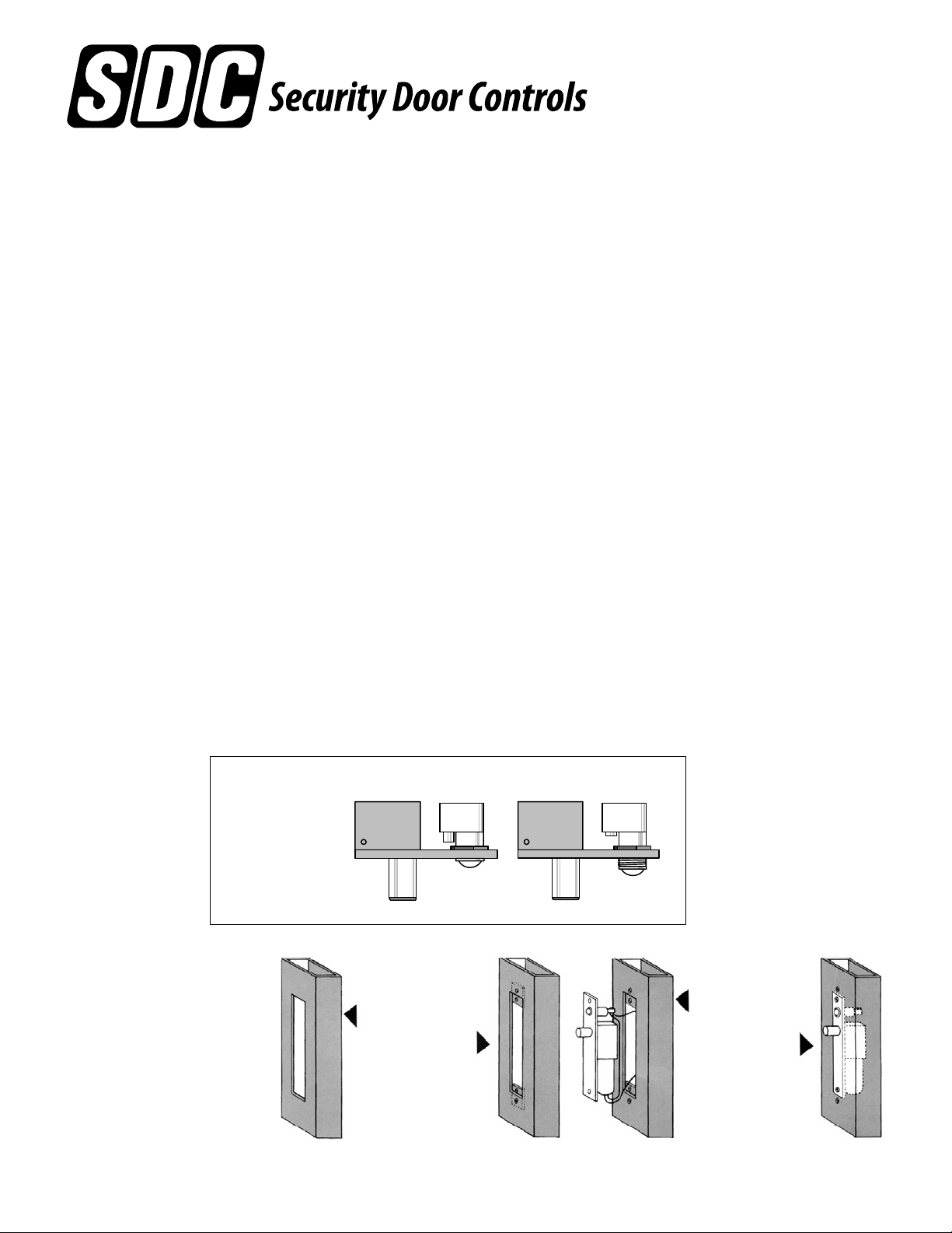
Auto Relock Switch
Adjustable for Wide Door Gap
Loosen nut.
Turn assembly
clockwise for wide
door gap.
Tighten nut.
Fig. 2
3. Connect wiring
to lock.
4. Slide lock into
position, attach
to tabs.
Easy Installation or Servicing
All Space Saver locks are
easily installed in any existing
entrance merely by mortising
out a cutout, attaching the
wiring, inserting the lock, and
bolting it into position with two
Fig. 1
1. Mortise cutout in
tube for face plate
(fits flush with
surface of tube).
2. Position screws
for attaching
tabs, drill holes,
attach tabs.
attaching tabs. Cutting studs is
no longer a problem or
expense.
P:\INSTALLATION INST\Electric Bolt Locks\INST-90 DEG Dual Coil\INST-90 DEG.vsd REV E 06-13 Page 1
Any suggestions or comments to this instruction or
product are welcome. Please contact us through
our website or email [email protected]
Page 2
1190A
Face plate: 8” x 1-1/2” x 0.125”
(203.2mm x 38.1mm x 3.175mm)
I.D. Requirements: 8” x 1-1/2” x 1-1/2”
(203.2mm x 38.1mm x 38.1mm)
Solenoid: Continuous duty
Standard voltage: 24VDC @ .7 Amp
Strike: M-Mortise 4” x 1-1/2” x 0.125” (101.6mm x 38.1mm x 3.175mm)
Bolt: 3/4” (6.35mm) dia. S.S., 3/4” (6.35mm) throw
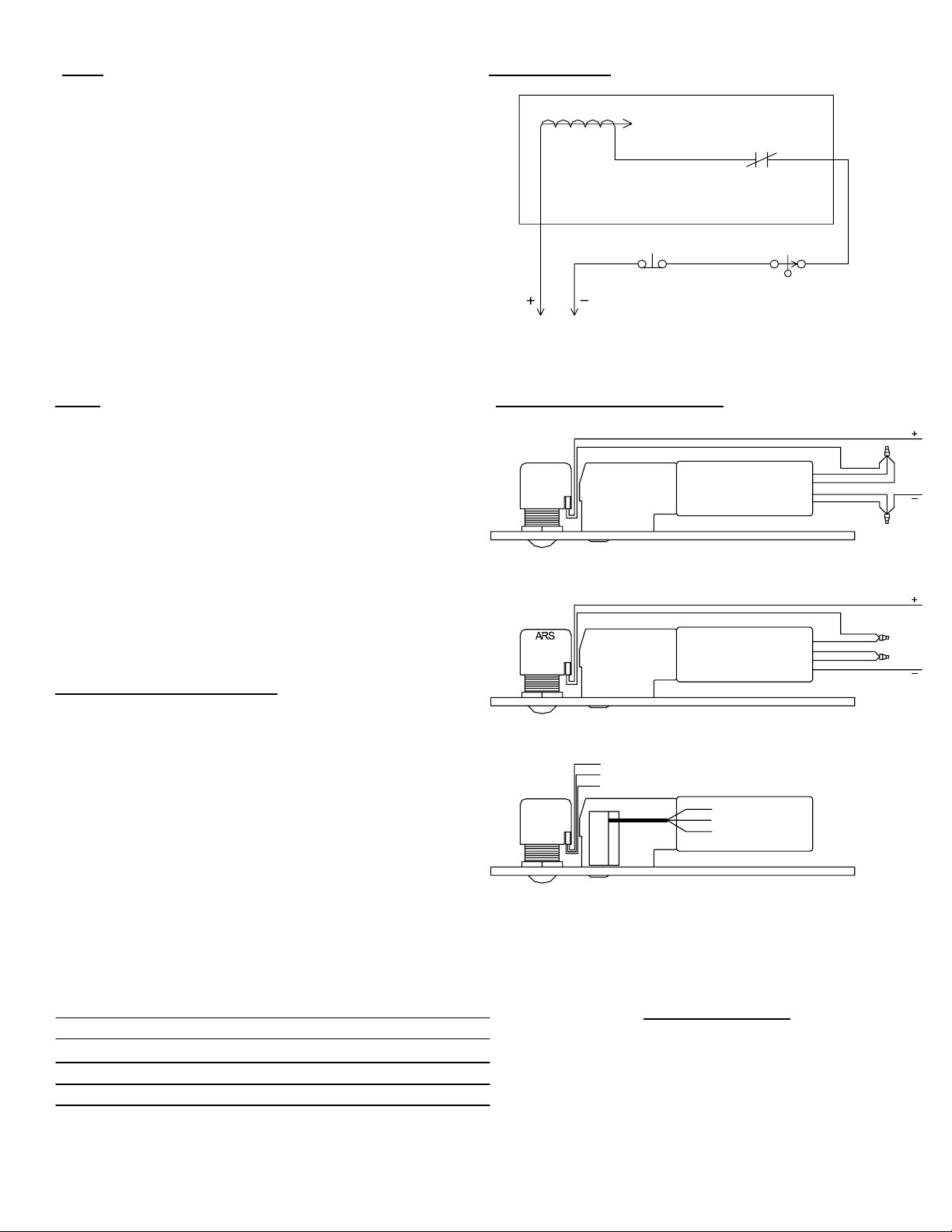
FOR 1190A ONLY:
RED
POWER
FOR FS23M AND 1091A/1091ADC:FS23M
A.R.S.
YELYELWHT
N.O.
ACCESS CONTROLS
N.C.
N.C.
DOOR IS SHOWN CLOSED AND LOCKED.
UNLOCKING MAY BE CONTROLLED BY
MULTIPLE SWITCH LOCATIONS.
Face plate: 8” x 1-1/2” x 1/8”
(203.2mm x 38.1mm x 3.175mm)
I.D. Requirements: 8” x 1-1/2” x 1-1/2”
(203.2mm x 38.1mm x 38.1mm)
Solenoid: Continuous duty
Dual Voltage:
12VDC@ .9 Amp
24VDC@ .45 Amp
Strike: M-Mortise 4” x 1-1/2” x 0.125” (101.6mm x 38.1mm x 3.1 75mm)
For wood 1-3/4” deep (44.45mm)
Bolt: 5/8” (15.88mm) dia. nylon with magnet insert, 5/8” (15.88mm)
throw.
Red pilot lamp standard to indicate door locked.
1091A/1091ADL (DEADLOCKING)
Face plate: 8” x 1-1/2” 0.125” (35.1mm x 35.1mm x 3.175mm)
1091STA: 4-7/8” x 1-1/4” x 0.0937” ANSI
(123.53mm x 31.75mm x 2.28mm)
I.D. Req. 8” x 1-1/2” x 1-1/2”
(203.2mm x 38.1mm x 38.1mm)
Solenoid: Continuous duty
Dual Voltage:
12VDC @ .9 AMP
24VDC @ .45 AMP
Strike: M-Mortise 4” x 1-1/2” x 0.125” (101.6mm x 38.1mm x 44 .45mm)
Bolt: 5/8” (15.88mm) dia. S.S., 3/4” (6.35mm) throw
ARS
DPS
12 VDC CONFIGURATION
24 V CONFIGURATION
RED = N/C
WHT = COM
BLU = N/O
BPS
CONTACT RATING
5 AMPS @ 125 VAC
DPS / BPS CONFIGURATION
YEL
YEL
YEL
YEL
RED = N/C
WHT = COM
BLU = N/O
RED
BLK
BLU
WHT
RED
BLK
BLU
WHT
BOLT POSITION SENSOR (MAGNETIC)
B Indicates bolt locked or unlocked .25 Amp
Problem Solution
Bolt does not project Check voltage and alignment
DOOR POSITION SWITCH (MECHANICAL)
D Indicates door opened or closed 5 Amp
Bolt projects but chatters Voltage too low.
Bolt will not retract Strike misaligned
P:\INSTALLATION INST\Electric Bolt Locks\INST-90 DEG Dual Coil\INST-90 DEG.vsd REV E 06-13 Page 2
TROUBLE SHOOTING
of strike.
 Loading...