

Page 1
SECURITY DOOR CONTROLS
3580 Willow Lane, Westlake Village, CA 91361-4921 • (805) 494-0622 • Fax: (805) 494-8861
www.sdcsecurity.com • E-mail: [email protected]
INSTALLATION INSTRUCTIONS
Model 936 EntryCheck
™
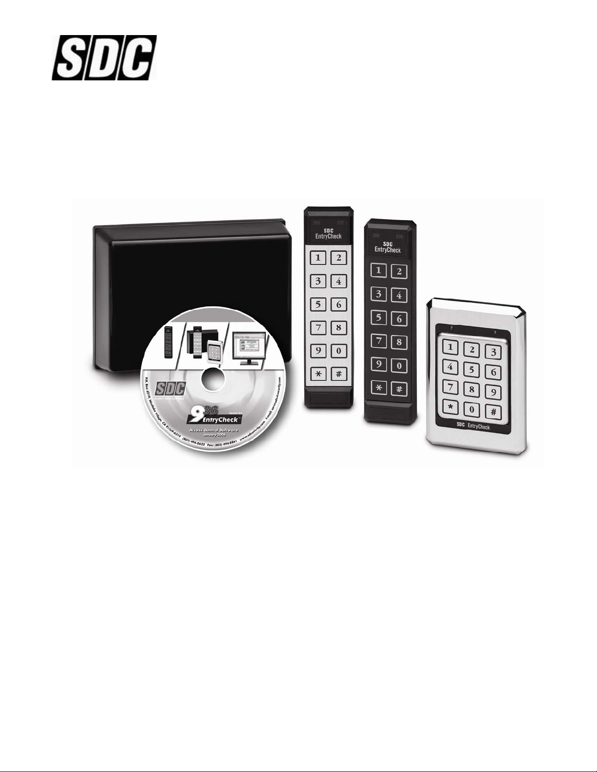
The 936 EntryCheck™ is a powerful yet easy to use, stand alone keyless entry system with features suitable for a
variety of access control requirements. Providing either a voltage output or dry contact closure, the 936 is designed
to control any fail-safe or fail-secure electric locking device.
™
The 936 EntryCheck
can accommodate up to 500 user codes, each assignable to one of three programmable
outputs. The 936 provides an enhanced level of security by storing the relay outputs in a separate control module.
The three relay outputs are available to provide a variety of access control configurations including single door
operation with two auxiliary output for a CCTV/Light Controller, Internal Alarm, 2nd/3rd Door, or Doorbell activation.
All user programming and system configuration can be performed through the Keypad or PC programming software.
Additional features include a tamper alarm, forced door alarm, door ajar alarm, remote bypass, time clock input, and
real-time event logging while connected to a PC.
P:\INSTALLATION INST\Access Control\INST-936.vsd 0106 Page i
Any suggestions or comments to this instruction or
product are welcome. Please contact us through
our website or email [email protected]
Page 2

TABLE OF CONTENTS
Introduction .................................................................................. 1
Overview - The 936 EntryCheck™ .................................................. 1
Keypad with Relay Control Module – Part Numbers....................... 1
Control Module Capabilities …........................................................ 2
Keypad Connector Diagram ........................................................... 3
Specifications ................................................................................. 4
Preparing for Installation ............................................................. 5
System Components ...................................................................... 5
The Installation Procedure ........................................................... 5
Required Tools ……......................................................................... 5
Prepare the Keypad for Installation.................................................. 6
Install the Wiring Cable .................................................................... 7
Installing the Control Module ........................................................... 7
Connecting the Locking Device ....................................................... 7
Hardware Setup ………….............................................................. 8
Voltage Selection …………............................................................. 8
Keypad Output Selection …………................................................. 8
Restoring System Defaults........................................................... 9
Keypad Reset …………................................................................... 9
Normal System Operation ......................................................... 10
Keypad LED Status Indicators ..................................................... 10
Tamper Alarm .............................................................................. 10
Control Module LED Status Indicators ......................................... 10
Operation Notes ........................................................................... 11
™
Using the 936 EntryCheck
Connecting the 936 EntryCheck
with a PC ...................................... 12
™
to a PC..................................... 12
Installing the CD-ROM................................................................... 12
Using Keypad Programmer Software. ........................................ 12
Using Keypad Logger Software. ................................................. 13
™
Programming the 936 EntryCheck
with the Keypad .............. 14
Programming the Control Module ................................................. 14
Programming Individual Users ...................................................... 18
936 EntryCheck
™
Diagrams ........................................................ 21
Control Module Circuit Board ........................................................ 21
Typical Hook-up Fail Safe or Fail Secure and CCTV Diagram ….. 22
P:\INSTALLATION INST\Access Control\INST-936.vsd 0106 Page ii
Page 3
INTRODUCTION
OVERVIEW - THE 936 EntryCheck
™
The SDC 936 EntryCheck™ Access Control System is an extremely versatile Keypad and
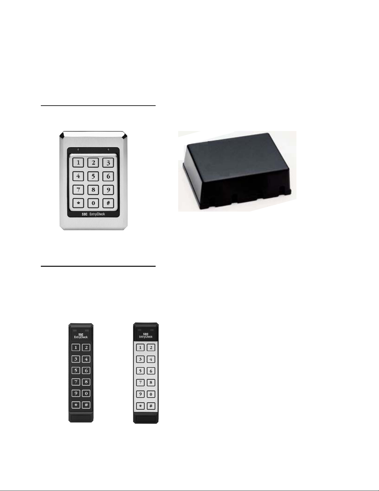
Relay Control Module. The 500-user code system consists of either a 3x4 or 2x6 Keypad
and a Relay Control Module.
KEYPAD WITH CONTROL MODULE - PART NUMBERS
3x4 Keypad with Control Module
P/N: 936 x KP-41U – Stainless Steel Bezel
KP-41U
936 RELAY CONTROL MODULE
2x6 Keypad with Control Module
P/N: 936 x KP-31Y – Black Illuminated
P/N: 936 x KP-31U – Stainless Steel Overlay
KP-31Y
P:\INSTALLATION INST\Access Control\INST-936.vsd 0106 Page 1
KP-31U
Page 4

CONTROL MODULE CAPABILITIES
Input Requirements
The Control Module accepts 12-24V AC/DC. System and Keypad current draw (max) is as
follows:
Standby: 50mA
During Operation: 150mA
Output Capabilities
Main Relay
The Main Relay will activate either a Fail-Safe or a Fail-Secure (Non Fail-Safe) electronic
locking device or other equipment. It may also be configured as a dry contact relay output to
control a gate operator or garage door opener. The main output is programmable from 01 to
99 seconds with optional timed or manual latching.
Output A
A relay contact output that can be programmed for one of the following:
1. CCTV or Light Controller -First key press triggers a Timed Output (1 to 99 seconds).
2. Auxiliary Output - Manual Control or Timed Output (1 to 99 seconds).
3. Second Door - Users can be assigned to open a 2nd door.
4. Doorbell - Press # at the Keypad to trigger a 1 second output for a doorbell (not included).
Output B
A relay contact output that can be programmed for one of the following:
1. CCTV or Light Controller -First key press triggers a Timed Output (1 to 99 seconds).
2. Auxiliary Output - Manual Control or Timed Output (1 to 99 seconds).
3. Third Door - Users can be assigned to open a 3rd door.
4. Internal Alarm System - Detect Break-in, Door-ajar & Tamper.
5. Doorbell - Press # at the Keypad to trigger a 1 second output for a doorbell (not included).
P:\INSTALLATION INST\Access Control\INST-936.vsd 0106 Page 2
Page 5
KEYPAD CONNECTOR DIAGRAM
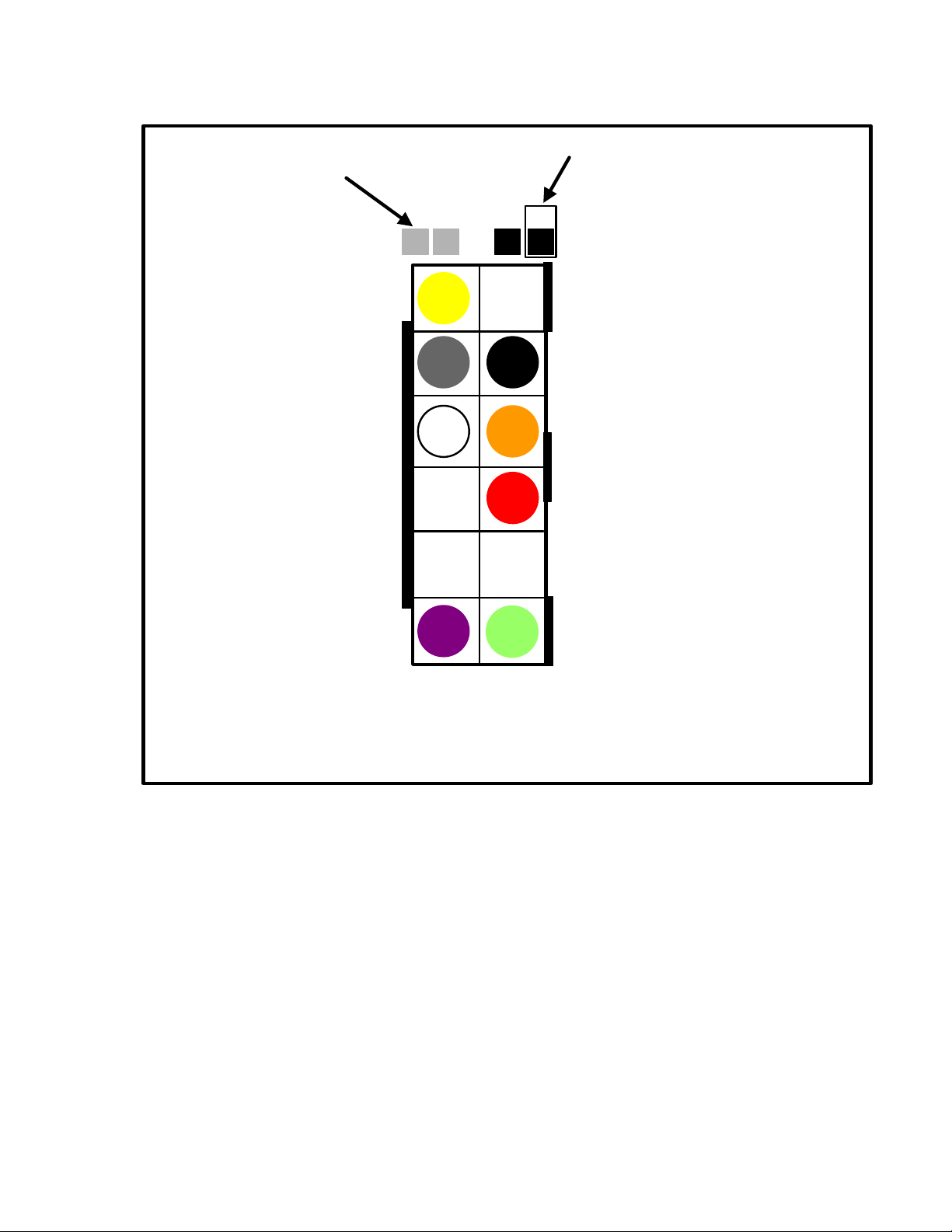
CONFIGURATION
PINS- “CONFIG”
YELLOW- Door Monitor
(Do NOT apply voltage)
GRAY*
SHIELD*
VOLTAGE SELECT
(Do NOT apply voltage)
12-24V (default)- Jumper on
one pin
5V- Jumper on both pins
BLACK*-Ground
ORANGE*- Program (Do NOT
apply voltage)
RED*- Input Voltage
VIOLET*
GREEN*- Output for Control
Module
*Connect to Control Module inputs
NOTE: The 2x6 connector is rotated 180 degrees
YELLOW- Anti Tailgate
If not used, this must be connected to BLACK. By adding a door monitor switch between
YELLOW and BLACK, the door will relock immediately after opening. If Output B is set up as
Internal Alarm, this switch will trigger the alarm if the door is opened without a code or if the door
is left open longer than the Door Ajar Time setting.
RED, BLACK, GREEN, VIOLET, GRAY, ORANGE and SHIELD – These wires all connect to
the Control Module.
TIME CLOCK
If TIME CLOCK is enabled in Set up (page 17), when the CLOCK terminal on the Control
Module circuit is connected to ground, through time clock or other switch contacts, all codes
work normally. When the CLOCK terminal is not grounded, only those codes with 24-hour
Access Authorization (page 18) will function. The disabled codes are still considered valid and
will not trigger the Tamper Alarm if tried repeatedly.
P:\INSTALLATION INST\Access Control\INST-936.vsd 0106 Page 3
Page 6
SYSTEM SPECIFICATIONS
Standby Current Draw: 50mA (including Keypad)
Input Voltage: 12 to 24V AC/DC
3 SPDT Relay Contacts at 6A (120VAC)Outputs:
Keypad Switch Life:
Keypad Operating
Environment:
3x4 Keypad Dimensions:
2x6 Keypad Dimensions:
3x4 Keypad Weight:
2x6 Keypad Weight:
Control Module Dimensions:
Control Module Operating
Environment:
>1 Billion Cycles
-40°F to + 160°F (-40°C to + 70°C)
100 % Relative Humidity
5 ⅛"H x 3 ⅜”W x 7/16"D (13 x 8.6 x 1.1cm)
7 ⅛"H x 1 ¾”W x ¾"D (18.1 x 4.4 x 1.9cm)
16 oz (454 gm)
4.4 oz (125 gm)
1 Red, 1 GreenLED’s:
5 ½"H x 7 ½"W x 2 ½"D
16 oz (454 gm)Control Module Weight:
-40°F to + 120°F (-40°C to + 49°C)
*The Control Module contains a serial interface to connect a PC for programming,
reading codes from a keypad, and logging transactions.
P:\INSTALLATION INST\Access Control\INST-936.vsd 0106 Page 4
COM Port (Serial)*Communication:
Page 7

PREPARING FOR INSTALLATION
936 EntryCheck
™
SYSTEM COMPONENTS
There are four primary components to be installed:
1. The Keypad should be mounted on the wall adjacent to the door. It should be on the
same side as the door strike and about 4 feet above the floor.
2. The Control Module should be mounted inside the building near a power source.
Typically the control module is hidden in a false ceiling or closet. The control module must
be located in an area where the temperature remains between -40°F and 120°F
(-40°C and +49°C).
3. The Wiring Cable connects the keypad to the control module. It is important not to locate
the cable adjacent to any wiring that carries line voltage. Included with the system is a 15foot 12 conductor jacketed wiring cable of which only 8 wires are used. If the Control
Module must be located further than 15 feet from the Keypad, additional cable may be
spliced. The maximum distance between the Keypad and the Control Module must not
exceed 1,000 feet. For runs over 200 feet, 18 gauge wire should be used. Under 200 feet,
20 gauge is acceptable.
4. The Electric Strike/Other Locking Device (not included) connects to the 936’s Relay
output(s) via the strike cable. (See Typical Wiring Diagrams pg 22). Please refer to the
installation instructions included with your locking device for specific mounting directions.
THE INSTALLATION PROCEDURE
REQUIRED TOOLS
You will need the following tools:
• Medium Phillips screwdriver
• ⅛" standard screwdriver
• Drill
• ⅞” or 1” (25mm) drill bit
• ½" (13mm) drill bit
5
/32" (4mm) drill bit
•
P:\INSTALLATION INST\Access Control\INST-936.vsd 0106 Page 5
Page 8

PREPARE THE KEYPAD FOR INSTALLATION
There are different procedures for mounting each Keypad. Identify the Keypad part number
and follow the appropriate mounting instructions below.
Mounting Instructions for KP-41U
The 3x4 keypad is designed to mount to a single gang switchbox or on a wall, pedestal or
any flat surface of at least 3 ½” by 5 ¼”. The composition of the mounting surface will
determine the fastening method required. If mounting to a surface other than a switchbox:
1. Select a flat surface (3 ½” by 5 ¼”) near the door where you wish to install the keypad.
2. Drill the large hole for the Keypad connector using a 1” (25mm) drill bit.
3. Place the connector on the back of the keypad in the large hole. Mark the keypad
mounting holes.
4. Drill clearance holes in accordance with fastening method used. (If mounting to wood,
drill small pilot holes and use #6 flat head wood screws provided. If mounting to metal,
drill two 5/32" clearance holes for #6 flat head machine screws provided.)
5. Do NOT mount the keypad at this time.
6. Proceed to Install the Wiring Cable.
Mounting Instructions KP-31U and KP-31Y
The 2x6 keypad is designed for mullion mount applications. It can also be mounted on a wall,
pedestal or any flat surface of at least 1 ¾” by 7”. The composition of the mounting surface will
determine the fastening method required:
1. Select a flat surface (1 ¾ ” by 7”) near the door where you wish to install the keypad.
2. Using the template, mark location of holes.
3. Drill the large hole using a 1” (25mm) drill bit.
4. Place the connector on the back of the keypad in the large hole to verify that the mounting
holes are aligned. Make adjustments if necessary.
5. Drill mounting holes in accordance with fastening method used. If mounting to wood, drill
small pilot holes and use #6 flat head wood screws provided. If mounting to metal, drill
5
/32" clearance holes for #6 flat head machine screws provided.
two
6. Do NOT mount the keypad at this time.
7. Proceed to Install the Wiring Cable.
P:\INSTALLATION INST\Access Control\INST-936.vsd 0106 Page 6
Page 9

INSTALL THE WIRING CABLE
1. Drill a ½” hole in the inside wall or ceiling where you want the cable to come through.
2. Pull cable through hole so the connector end goes to keypad. Route so there is minimal
cable at the keypad.
NOTE: Supplied with the system is a 12-conductor cable designed to connect keypad to
control module. You will also need a 3-conductor cable (not included) to connect the control
module to an electric strike or other locking device(s).
3. Attach the wiring connector to the Keypad.
4. Attach the Keypad to the wall.
5. Do NOT mount the Keypad labels until the system is programmed and tested.
INSTALLING THE CONTROL MODULE
1. Connect the Wiring Cable to Terminal Strip “A” following the color sequence on the circuit
™
board. (see 936 EntryCheck
Diagrams, pg 21)
2. Connect 12 to 24 Volts AC to Terminal Strip “C” to screws marked “12-24V AC IN”. If using
an external AC Adaptor, connect BLUE and BROWN to the 12-24V input screws. Connect
GREEN to the “EARTH” screw on Terminal Strip “A”. Plug adapter into a grounded (three
terminal) receptacle.
3. If connecting DC, make connections to Terminal Strip “B”, “DC IN/OUT” instead of “12-
24V AC IN”. Be sure polarity is correct.
IMPORTANT: The “EARTH” screw terminal on Terminal Strip “A” should be connected to a
true earth ground for proper system protection and operation.
CONNECTING THE LOCKING DEVICE
Connect the electric locking device to Terminal Strip “B” as outlined in the Typical Wiring
Diagram (see pg 22). Any 3 conductor, 18 gauge wire can be used to connect the Control
Module to the Locking Device. Included with each system are two MOV’s (metal oxide
varistor). The function of the MOV is to absorb any inductive kickback from the locking
device, protecting the circuit board. The MOV’s have been installed under the relay contact
screws and can be left there for normal “FAIL SECURE” lock operation. For “FAIL SAFE”
locks, move one leg from the “N.O.” screw to the “N.C.” screw (see pg 21-22). If possible,
install the MOV closer to the electric lock. For switching voltages higher than 36V, remove
the MOV. To provide proper grounding, connect the 3
rd
wire from the body of the locking
device to the “EARTH” screw on Terminal “A”.
BATTERY BACKUP
Battery backup is NOT required for User Code retention, however, you may wish to connect
an SDC Power Supply with battery backup to provide operation during a power interruption.
P:\INSTALLATION INST\Access Control\INST-936.vsd 0106 Page 7
Page 10

HARDWARE SETUP
VOLTAGE SELECTION
The factory default setting for the Keypad voltage is 12-24VDC. Verify that the jumper is
removed or placed over only one pin. If changing the voltage is necessary, make sure the
power is removed first.
KEYPAD OUTPUT SELECTION
IMPORTANT: Perform steps 1 through 9 below before configuring the control module
or programming users.
Once the voltage jumper is verified or correctly set:
1. Remove power.
2. Jumper the two pins above the connector labeled “CONFIG”.
3. Apply appropriate power. (You should hear 4 beeps and the RED LED will flash and the
GREEN LED will be solid).
4. Now that the Keypad is in configuration mode, enter 98 followed by #. You should hear 3
beeps indicating successful configuration (the RED LED will continue to flash and the
GREEN LED will be solid). If you hear a long error beep, reenter 98 followed by #. To change
the audible beep or illumination, proceed as follows. Otherwise, go to step 5.
a. To change the audible beep, enter
Code Audible Beep
201 # Normal Beep (factory default)
200 # Short Click (quieter)
b. To change the illumination on the KP-31Y only, enter the code as follows:
Code Standby Mode Normal Operation
210 # Off (factory default) Off (factory default)
211 # Off Dim
212 # Off Bright
213 # Dim Dim
214 # Dim Bright
5. Remove power.
6. Remove configuration jumper.
7. Re-apply power.
8. Press the PROGRAM button in the Control Module to establish the encoded connection.
This will put the system into setup mode.
9. Press * * to exit.
NOTE: If the configuration jumper is not removed, the LED's will flash and the
Keypad will beep continuously.
P:\INSTALLATION INST\Access Control\INST-936.vsd 0106 Page 8
Page 11

RESTORING SYSTEM DEFAULTS
KEYPAD RESET
In certain cases you may want to erase all user codes and restore system defaults. To
perform this procedure:
CAUTION: This procedure completely erases the memory and restores factory
defaults! Once the memory is cleared, all programmed User Codes are erased
and factory default settings are restored.
1. Remove power.
2. Jumper the two pins above the connector labeled “CONFIG”.
3. Apply appropriate power. (You should hear 4 beeps and the RED LED will flash and the
GREEN LED will be solid).
4. Once the Keypad is in configuration mode, enter 0099#. The Keypad will beep twice and
both LEDS will flash for approximately 10 seconds. (During this time, the Keypad will appear
dead. Do NOT remove power!)
5. Enter 98 followed by #. You should hear 3 beeps indicating successful completion (the
RED LED will continue to flash and the GREEN LED will be solid). If you hear a long error
beep, re-enter 98 followed by #. To change the audible beep or illumination, proceed as
follows. Otherwise, go to step 6.
a. To change the audible beep, enter the code as follows:
Code Audible Beep
201 # Normal Beep (factory default)
200 # Short Click (quieter)
b. To change the illumination on the KP-31Y only, enter the code as follows:
Code Standby Mode Normal Operation
210 # Off (factory default) Off (factory default)
211 # Off Dim
212 # Off Bright
213 # Dim Dim
214 # Dim Bright
6. Remove power.
7. Remove configuration jumper.
8. Re-apply power.
9. Press the PROGRAM button in the Control Module to establish the encoded connection.
This will put the system into setup mode.
10. Press * * to exit.
P:\INSTALLATION INST\Access Control\INST-936.vsd 0106 Page 9
Page 12

NORMAL SYSTEM OPERATION
When the system is first powered up (or when communication is broken between the Keypad
and the Control Module), the PROGRAM button in the Control Module must be pressed to
establish the encoded connection. This also puts the system into setup mode. To end, press
* * to exit. Or, the system will automatically exit programming if no entries are made for 30
seconds.
KEYPAD LED STATUS INDICATORS
A flashing green LED indicates that the door is unlocked (momentarily).
A solid green LED indicates that the door is unlocked (latched).
A solid red LED indicates that the door is locked.
Depending on how the System Options are configured, User Commands are used to operate
Manual Latching. The User Commands are trailing digits entered after an authorized user
code. The ability to use these User Commands depends on authorizations assigned to each
User (see pages 18-19).
As the Main Output activates, the green LED will flash for 5 seconds. While the green LED is
flashing, enter one (or more) of the following User Commands:
0 # to Latch the Door Closed (Main Relay, 2nd Door or 3rd Door)
1 # to Latch the Door Open (Main Relay, 2nd Door or 3rd Door)
2 # to Turn Output A OFF (2nd Output as Aux.)
3 # to Turn Output A ON (2nd Output as Aux.)
4 # to Turn Output B OFF (3rd Output as Aux.)
5 # to Turn Output B ON (3rd Output as Aux.)
TAMPER ALARM
An audible Tamper Alarm sounds when four incorrect code entries are made. After 30
seconds, the unit returns to standby mode.
CONTROL MODULE LED STATUS INDICATORS
Mode Green Red
Normal Operation On Off
Lockup Mode On Flashing
Setup Mode Flashing Off
Connection Problems Off On
P:\INSTALLATION INST\Access Control\INST-936.vsd 0106 Page 10
Page 13

OPERATION NOTES
Pressing the PROGRAM button on the Control Module sets a new Encode Code (EC)
between the Control Module and the Keypad and puts the Keypad into Programming Mode. If
no further programming is required, press * * to exit.
If the Control Module receives more than three (3) invalid EC’s in a row, the unit will go into
LockUp Mode. Once in LockUp Mode, the unit is essentially shut down and can only be
restored to normal operation by pressing the PROGRAM button.
Upon communication loss or LockUp, all relays are released and the Main Door latching is
cleared if set. The Remote Bypass will not work and the Keypad will be forced to the non-24
hour mode if enabled. If communication is lost for more than 2 seconds, the unit goes into
LockUp Mode and can only be restored to Normal Operation by pressing the PROGRAM
button.
If communication is lost with the Control Module or the Control Module is in LockUp Mode,
the Keypad will indicate the problem by flashing the Red LED very fast.
Since the Encode Code (EC) is only sent at the beginning of a Latch Open sequence, this is
the only time the unit knows if the EC’s match. Upon a power up, both units will communicate
with each other and the second and third relays, remote bypass and clock input will work
normally. Upon the first attempt to send an Control Module packet with a non-matching EC,
the device will be put into the LockUp mode, and from that point, until a new EC is
programmed, the unit will essentially be shut down.
Pressing the PROGRAM button while the unit has lost communication can cause the EC to
be erased and will require an EC setup upon re-establishing communication. For this reason,
it is recommended that the Keypad and the Control Module be powered by the same power
supply so they are both powered up and down at the same time.
Since the output is on to indicate a Non-Alarm status when using Output B relay as an Alarm,
a loss of communication or invalid EC will always create an alarm indication.
P:\INSTALLATION INST\Access Control\INST-936.vsd 0106 Page 11
Page 14
USING THE 936 EntryCheck™WITH A PC
CONNECTING THE 936 EntryCheck™ TO A PC
Connect the Control Module to a PC using a serial cable (not included) through the Serial
COM Port. (The Control Module is set for 9600 baud.)
INSTALLING THE CD-ROM
If the installation does not begin automatically, Install “Setup.exe” from the enclosed CD. The
files will default to C:/Program Files/SDC/EZKey unless otherwise re-directed.
USING KEYPAD PROGRAMMER SOFTWARE
1. Double-Click on the “SDC EZKeys Prog” icon.
2. Click “Set Up” and select appropriate options and COM Port.
3. Click “OK.”
Program Codes Tab
While on the “Program Codes” tab, enter the Keypad Master Code (default: 123) at the
bottom of the window.
To add a code, double-click an empty line or click [ ] and fill in the blanks.
To delete a code, highlight the code line and click [ ].
To change user options / authorizations, double-click the code line.
When finished, save the code chart file in either protected or unprotected format and upload
[ ] to the Control Module. If programming has been done at the Keypad, you can download
from the Keypad to a blank code chart (names are not stored in the Keypad so they will be
blank) or MERGE [ ] the Keypad information with an existing code chart. If there are
conflicts (e.g., two User Number 1's), you will be asked to select a resolution. Once complete,
you will need to save the chart and upload to the Keypad to make sure they both agree.
Temporary (Temp) Code Tab
You can program ONE temporary code that will be good for up to 99 hours 59 minutes.
To add a temp code:
1. Enter the Temp Code PIN.
2. Enter the number of hours and minutes you would like to use the temp code.
3. Check the “Allow 24 Hour Access” box, if a time clock is used.
4. Click on SET CODE to upload the temp code to the keypad.
GET CODE will download the current temp code from the keypad, if any.
To delete a temp code, click on GET CODE and then click on DELETE CODE.
Configuration Tab
Select GET CONFIGURATION to download the current Control Module configuration. Make
any changes to the existing configuration and then select SET CONFIGURATION to upload.
To change the Master Code, enter the new master code (3-8 digits) ,select SET MASTER,
and confirm changes.
P:\INSTALLATION INST\Access Control\INST-936.vsd 0106 Page 12
Page 15

USING KEYPAD LOGGER SOFTWARE
Running this log will record all actions of the 936 EntryCheck™. You can also print up to the
last 500 transactions. The date and times are taken from the computer, not the 936
EntryCheck™.
1. Double-Click on the “SDC EZKeys Log” icon.
2. Click “Set Up” and select appropriate options and COM Port.
3. Click “OK.”
4. Click on the GREEN square icon to start logging. To stop logging events and place the
program in “idle” mode, click on the RED square icon.
NOTE: You cannot use the Keypad Programmer while the Keypad Logger is running.
To clear the log, stop the event logger. Select the OPERATION menu, and CLEAR LOG.
Set up
If BIND is blank, the log will only list the User Number along with the action. If you BIND to an
existing Keypad Program File (see previous section), the user name will also be listed.
Select “Options” and “COM Port.”
Alarms
Loss of power- reported when power is restored.
Tamper Alarm- 4 incorrect code entries
Loss of communication between Keypad and Control Module (Keypad removed or broken
connection).
P:\INSTALLATION INST\Access Control\INST-936.vsd 0106 Page 13
Page 16
Programming the Control Module with the Keypad
To set up and program the system using the Keypad, proceed as follows. The System
Setup can only be modified if you know the Master Code (Default: 123). When the system is
initially set up, the default system settings should be reviewed prior to other programming.
To enter Control Module Setup mode:
Enter * 3
Enter the Master Code followed by #
Example: * 3 1 2 3 #
Proceed to one of the following eight programming options:
1.) Changing the Master Code (Default: 123)
A. Enter 1 #
B. Enter the New Master Code (3-8 digits) followed by #
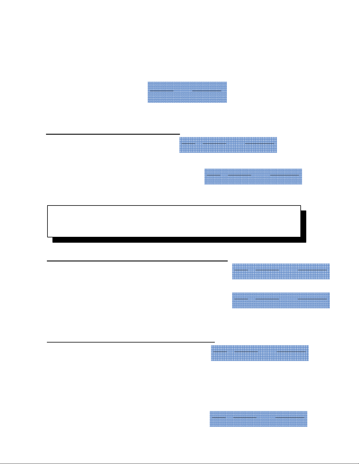
Red LED Green LED
Fast Flash Solid
Beep Red LED Green LED
Double Fast Flash Slow Flash
Beep Red LED Green LED
Triple Fast Flash Solid
C. Select another programming option (1-8) or enter * * to exit programming.
Note: If you forget the Master Code, locate and press the PROGRAM button on
the Control Module board. This will take you into System Setup. Once you enter
setup mode, you have 30 seconds to begin the program sequence.
2.) Setting the Main Door Open Time (Default: 5 Seconds)
A. Enter 2 #
Beep Red LED Green LED
Double Fast Flash Slow Flash
B. Enter the desired Door Open Time (1-99 seconds), followed by #
Example: 2 # 1 5 # (15 sec. Door Open Time)
Beep Red LED Green LED
Triple Fast Flash Solid
C. Select another programming option (1-8) or enter * * to exit programming.
3.) Setting Latching Option (Main Relay) (Default: Off)
A. Enter 3 #
Beep Red LED Green LED
Double Fast Flash Slow Flash
B. Select the desired latching option:
Off – 0 #
Manual – 9 9 #
Timed – Enter the desired time interval in hours (1-98), followed by #.
Example: 3 # 8 # (Sets timed latching for 8 hrs)
C. Select another programming option (1-8) or enter * * to exit programming.
P:\INSTALLATION INST\Access Control\INST-936.vsd 0106 Page 14
Beep Red LED Green LED
Triple Fast Flash Solid
Page 17

4.) Configuring Output A (Default: Aux #1)
A. Enter 4 #
B. Select one of the following (1 - 4):
i) CCTV / External Light
a. Enter 1 #
b. Enter the desired On Time (1-99 seconds), followed by #
Example: 4 # 1 # 1 5 # (Sets CCTV/Light Option for 15 seconds)
ii) Auxiliary Device #1
a. Enter 2 #
b. Enter the momentary output time (1-99 seconds), followed by # ; -or- Enter 0 to set the
auxiliary device for Manual Operation (ON/OFF), followed by #
Example: 4 # 2 # 0 # (Sets Auxiliary Device with Manual Operation)
iii) Second Door
a. Enter 3 #
b. Enter the desired Door Open Time (1-99 seconds), followed by #
c. Select the desired latching method:
Off- 0 #
Manual- 9 9 #
Timed-Enter the desired time interval in hours (1-98), followed by #
Example: 4 # 3 # 5 # 9 9 # (Sets Second Door with 5 second Door Open Time and Manual Latching)
iv) Doorbell
a. Enter 4 #
Example: 4 # 4 #
C. Select another programming option (1-8) or enter * * to exit programming.
Step Beep Red LED Green LED
ADouble Fast FlashSlow Flash
aDouble Fast FlashFast Flash
bTriple Fast FlashSolid
P:\INSTALLATION INST\Access Control\INST-936.vsd 0106 Page 15
Page 18

5.) Configuring Output B (Default: CCTV)
A. Enter 5 #
B. Select one of the following (1-5):
i) CCTV / External Light
a. Enter 1 #
b. Enter the desired On Time (1-99 seconds), followed by #
Example: 5 # 1 # 1 5 # (Sets CCTV/Light Option for 15 seconds)
ii) Auxiliary Device #2
a. Enter 2 #
b. Enter the momentary output time (1-99 seconds), followed by # ; -or- Enter 0 to set the
auxiliary device for Manual Operation (ON/OFF), followed by #
Example: 5 # 2 # 0 # (Sets Auxiliary Device with Manual Operation)
iii) Third Door
a. Enter 3 #
b. Enter the desired Door Open Time (1-99 seconds), followed by #
c. Select the desired latching method:
Off- 0 #
Manual- 9 9 #
Timed- Enter the desired time interval in hours (1-98), followed by #
Example: 5 # 3 # 5 # 9 9 # (Sets Second Door with 5 second Door Open Time and Manual Latching)
iv) Doorbell
a. Enter 4 #
Example: 5 # 4 #
v) Internal Alarm
a. Enter 5 #
b. Enter the desired Door Ajar Time (1-99 seconds), followed by #
Example: 5 # 5 # 1 0 # (Sets Internal Door with 10 second Door Ajar Time)
C. Select another programming option (1-8) or enter * * to exit programming.
Step Beep Red LED Green LED
ADouble Fast FlashSlow Flash
aDouble Fast FlashFast Flash
bTriple Fast FlashSolid
P:\INSTALLATION INST\Access Control\INST-936.vsd 0106 Page 16
Page 19

6.) Master Code Door Unlock Option (Default: Allow)
A. Enter 6 #
B. Enter 0 # to prevent the master code from unlocking the door.
C. Enter 1 # to allow the master code to unlock the door.
D. Select another programming option (1-8) or enter * * to exit programming.
7.) Time Clock Input (Default: Prevent)
A. Enter 7 #
B. Enter 0 # to prevent lockout
C. Enter 1 # to lockout all users that do not have 24 hour option enabled.
D. Select another programming option (1-8) or enter * * to exit programming.
8.) Baud Rate (if using Keypad with Control Module)
A. Enter 8 #
B. Enter 0 # to set Baud Rate to 2400
C. Enter 1 # to set Baud Rate to 9600 (default)
D. Select another programming option (1-8) or enter * * to exit programming.
Enter * * to complete the sequence and reset the system to normal operation.
Note:
If using a printer, 0 # will print Setup Configuration
P:\INSTALLATION INST\Access Control\INST-936.vsd 0106 Page 17
Page 20
Programming Individual Users with the Keypad
Authorized users (master code or any user authorized to program) can program users
directly from the Keypad. Each Individual User can be assigned various authorizations.
Review System Setup before programming individual users.
To enter User Programming mode:
Enter * 1
Enter the Master Code (Default: 123) followed by #
Example: * 1 1 2 3 #
NOTE: Once an authorized user enters programming mode, any combination of adding, modifying or deleting Users can
be performed without having to re-enter these steps each time. However, if more than 30 seconds elapse between each
step during programming, the system will reset and you will have to start from beginning.
Proceed to one of the following seven programming options:
1.) Adding a New User
A. Enter 1 #
B. Enter the User ID (1 to 499) followed by #
C. Enter the User Code/PIN (3-8 digits), followed by #
D. Enter the desired User Authorization Code (see below), followed by # (Repeat for additional
authorizations or skip to Step E for no authorizations.)
Code User Authorization
1 Latching Authorization
2 Program or Delete Users Authorization
3 Output A Authorization (see notes)
4 2nd Door (see notes)
5 Output B Authorization (see notes)
6 3rd Door (see notes)
7 24-hour Access (see notes)
E. Once all desired User Authorizations have been assigned, enter # to complete programming for this
User.
F. To program an additional User, return to Step B.
G. If no more Users are to be added, enter * * to select another programming option (1-7), or if you have
completed all User Programming, enter * * a second time to complete programming sequence and reset
system to normal operation.
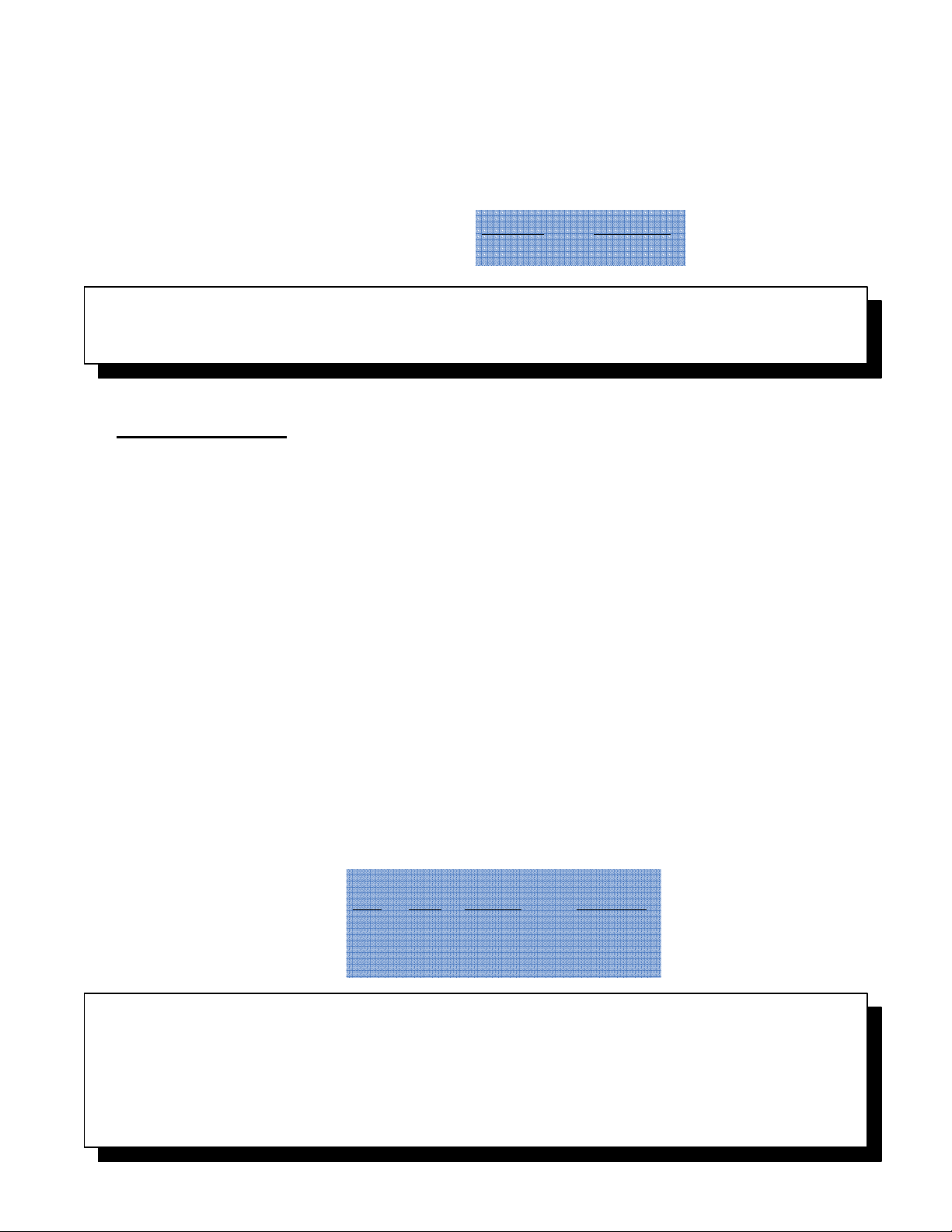
Keypad Status After Step Completion
Step
A Double Slow Flash Slow Flash
B-E Double Slow Flash Fast Flash
F Triple Slow Flash Slow Flash
Beep Red LED Green LED
Red LED Green LED
Slow Flash Solid
NOTES:
1. Auxiliary Device or 2nd or 3rd Door authorization depends on configuration of the A and B Outputs. See Control Module
Setup on pages 15-16.
2. If either Output is configured for 2nd or 3rd Door operation and a user is given 4# or 6# Authorization, their User Code will
activate the configured output, not the Main Relay.
3. 24 Hour Access requires an external time clock or keyswitch. This allows you to restrict access to Users who are not
assigned 24-hour Access. See Time Clock Input on page 3.
P:\INSTALLATION INST\Access Control\INST-936.vsd 0106 Page 18
Page 21

2.) Modify a User by User ID
A. Enter 2 #
B. Enter the User ID (1 to 499) for the User to be modified, followed by #
C. To change this User’s Code, enter the New User Code followed by #
D. To keep this User’s Code, enter #. Then, enter the desired User Authorization (see below),
followed by #. (Repeat for additional authorizations or skip to Step E for no authorizations.)
Code User Authorization
1 Latching Authorization
2 Program or Delete Users Authorization
3 Output A Authorization (see notes)
4 2nd Door (see notes)
5 Output B Authorization (see notes)
6 3rd Door (see notes)
7 24-hour Access (see notes)
E. Enter # to complete programming for this User.
F. To modify an additional User, return to Step B.
G. If no more Users are to be modified, enter * * to select another programming option (1-7), or if you
have completed all User Programming, enter * * a second time to complete programming sequence and
reset system to normal operation.
3.) Modify a User by User Code
A. Enter 3 #
B. Enter the User Code for the User you wish to modify, followed by #
C. To change this User’s Code, enter the New User Code followed by #
D. To keep this User’s Code, enter #. Then, enter the desired User Authorization, followed by #. (Repeat
for additional authorizations or skip to Step E for no authorizations.)
Code User Authorization
1 Latching Authorization
2 Program or Delete Users Authorization
3 Output A Authorization (see notes)
4 2nd Door (see notes)
5 Output B Authorization (see notes)
6 3rd Door (see notes)
7 24-hour Access (see notes)
E. Enter # to complete programming for this User.
F. To modify an additional User, return to Step B.
G. If no more Users are to be modified, enter * * to select another programming option (1-7) or if you have
completed all User Programming, enter * * a second time to complete programming sequence and reset
system to normal operation.
Note on Modifying Users:
Once you have begun to modify a User, previously programmed authorizations are deleted for this User.
P:\INSTALLATION INST\Access Control\INST-936.vsd 0106 Page 19
Page 22

4.) Deleting a User by User ID
A. Enter 4 #
B. Enter the User ID (1 to 499) for the User to be deleted, followed by #
C. To delete an additional User, return to Step B.
D. If no more Users are to be deleted, enter * * to select another programming option (1-7), or if you have
completed all User Programming, enter * * a second time to complete programming sequence and reset
system to normal operation.
5.) Deleting a User by User Code
A. Enter 5 #
B. Enter the User Code to be deleted, followed by #
C. To delete an additional User, return to Step B.
D. If no more Users are to be deleted, enter * * to select another programming option (1-7), or if you have
completed all User Programming, enter * * a second time to complete programming sequence and reset
system to normal operation.
6.) Adding a Temporary User
a. Enter 6 #
b. Enter the User Code / PIN (3-8 digits), followed by #
c. Enter the desired Temporary access Time (1-99 hours), followed by #
d. For 24-hour Access, enter 0 for No or 1 for Yes, followed by #
e. Enter * * to select another programming option (1-7), or if you have completed all User Programming,
enter * * a second time to complete programming sequence and reset system to normal operation.
7.) Deleting a Temporary User
a. Enter 7 #
b. Enter * * to select another programming option (1-7), or if you have completed all User Programming,
enter * * a second time to complete programming sequence and reset system to normal operation.
P:\INSTALLATION INST\Access Control\INST-936.vsd 0106 Page 20
Page 23
™
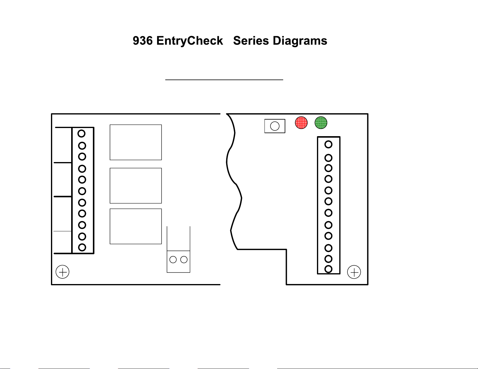
Control Module Circuit Board
NC 3
NO 3
COM3
NC 2
NO 2
COM2
NC 1
NO 1
COM1
12-24
DC IN/
OUT
B
11
10
PROGRAM
RED
GREEN
RELAY 3
9
8
7
6
RELAY 2
12
11
10
9
8
A
GND
BLACK
+12V
RED
VIOLET
GRAY
Clock
Terminals 2, 3, 4, 9,
10, 11, 12 to the
keypad
Terminals 7, 8 to
Clock or keyswitch
contacts.
Terminals 5,6 to
Remote Release
5
4
3
+
-
2
1
RELAY 1
12-24
AC IN
C
1 2
7
6
5
4
3
2
1
TO EARTH
Ground
Remote
Ground
ORANGE
GREEN
SHIELD
Button
If Door Monitor
switch is NOT used
connect keypad
Yellow to Black.
P:\INSTALLATION INST\Access Control\INST-936.vsd 0106 Page 21
Page 24
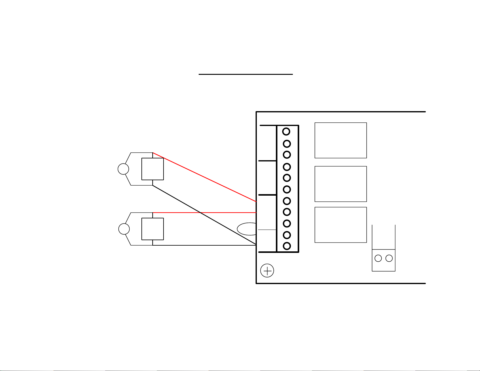
MOV
+
FAIL
SAFE
LOCK
-
Typical Wiring Diagram
NC 3
NO 3
COM3
NC 2
NO 2
COM2
B
11
10
RELAY 3
9
8
7
6
RELAY 2
+
FAIL
MOV
SECURE
LOCK
-
P:\INSTALLATION INST\Access Control\INST-936.vsd 0106 Page 22
NC 1
NO 1
COM1
12-24
DC IN/
OUT
5
4
3
+
-
2
1
RELAY 1
12-24
AC IN
C
1 2
 Loading...