

Page 1
SECURITY DOOR CONTROLS
3580 Willow Lane, Westlake Village, CA 91361-4921 • (805) 494-0622 • Fax: (805) 494-8861
www.sdcsecurity.com • E-mail: [email protected]
INSTALLATION INSTRUCTIONS
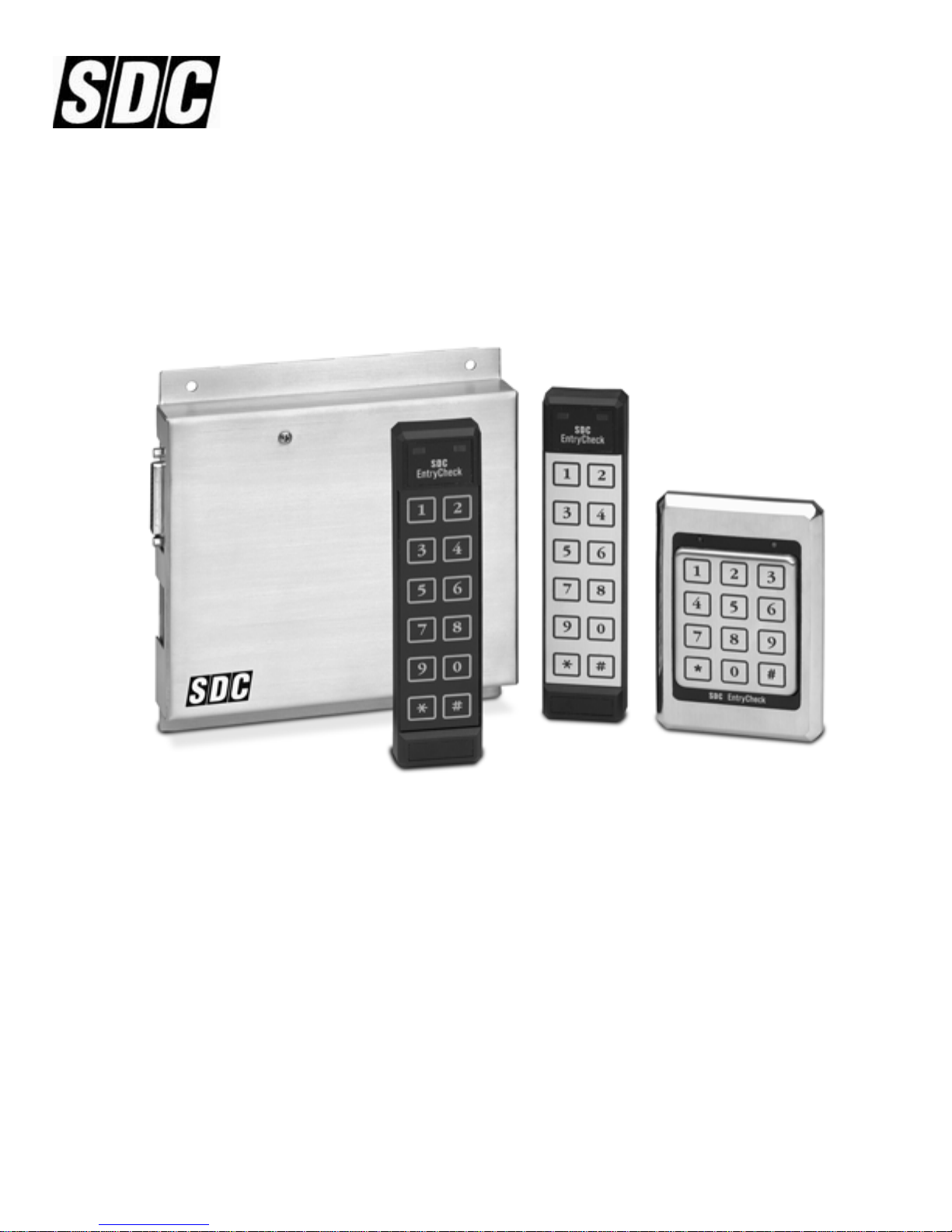
Model 935 EntryCheck™
The 935 EntryCheck™ is a powerful yet easy to use, stand-alone keyless entry system with features
suitable for a variety of access control requirements. Providing either a voltage output or dry contact
closure, the 935 is designed to control any fail-safe or fail-secure electric locking device.
™
The 935 EntryCheck
can accommodate up to 500 individual Users, each of which is assigned to one of
16 programmable User Groups. Some additional features include a 32-day holiday schedule, manual or
timed latching capabilities, and a built-in audit trail. The 935 contains a 24-hour nonvolatile real time
clock. The time clock enables access control management through individual time zones tied to each
User Group and is also used to provide a time/date stamp for the last 750 transactions, which are logged
in the 935's buffered audit trail. These transactions can easily be retrieved from a parallel printer
connected directly to the 935 EntryCheck
P:\INSTALLATION INST\ACCESS CONTROL\INST-935.vsd 0505 Page 1
™
control module.
Any suggestions or comments to this instruction or
product are welcome. Please contact us through
our website or email [email protected]
Page 2

Table of Contents
SYSTEM SPECIFICATIONS 3
INPUT REQUIREMENTS 4
OUTPUT CAPABILITIES 4
OPERATING TEMPERATURES 4
PREPARING FOR INSTALLATION 5
SYSTEM COMPONENTS 5
THE INSTALLATION PROCEDURE 5
REQUIRED TOOLS 5
PREPARE THE KEYPAD FOR INSTALLATION 5-6
INSTALL THE WIRING CABLE 7
MOUNT THE KEYPAD 7
PREPARE THE DOOR FOR THE ELECTRIC STRIKE 7
INSTALLING THE CONTROL MODULE 7
CONNECTING THE LOCKING DEVICE 8
SYSTEM HARDWARE SETUP 8
REMOTE BY-PASS 8
ANTI-TAILGATING 8
BATTERY BACKUP 8
OVERVIEW OF SYSTEM PROGRAMMING 9
SYSTEM SETUP 10
THE MASTER CODE 10
DOOR OPEN TIME / MAIN RELAY OUTPUT TIME 10
LATCHING 10
DURESS CODES 10-11
AUTOMATIC FEED LINE 11
DAYLIGHT SAVINGS TIME 12
PROGRAMMING SYSTEM SETUP 13-15
PROGRAMMING THE TIME CLOCK 16
PROGRAMMING THE HOLIDAY SCHEDULE 17
USER GROUPS 18
MODIFYING USER GROUPS 19-21
PROGRAMMING INDIVIDUAL USERS 22-24
NORMAL OPERATION 25
USER COMMANDS 25
TROUBLESHOOTING 26
APPENDIX A – CIRCUIT BOARD LAYOUT 27
APPENDIX B –TYPICAL WIRING DIAGRAMS 28
APPENDIX C – USER PROGRAMMING FORM 29
APPENDIX D – USER GROUP CONFIGURATION 30
P:\INSTALLATION INST\ACCESS CONTROL\INST-935.vsd 0505 Page 2
Page 3
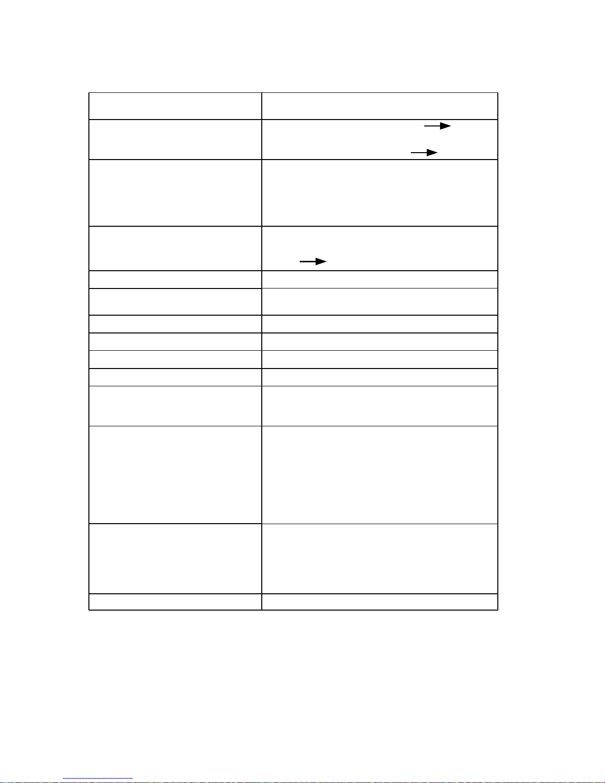
SYSTEM SPECIFICATIONS
Input Requirements: 12 to 24V AC/DC
Standby Current Draw:
12 or 24V w/ Non Illuminated Keypad 60mA
12 or 24V w/ Illuminated Keypad 100mA
3 SPDT Relay contacts at 6 Amps (120VAC)
Outputs:
Programmable Output
(Door Open Time)
Latching:
# of User Codes:
Code Length:
Access Code Protection:
Keypad Operating Environment:
Keypad Dimensions:
12-Pad 3x4
Voltage or Dry Contact
Fail Safe or Fail Secure Relay Configuration
1 to 99 seconds
Default 5 seconds
Off (Default) Manual (Toggle On/Off), Timed
500 Codes (1 Master, 499 User)
3 to 8 Digits
1-2-3Default Master Code:
3 Incorrect Code AttempsTamper Alarm:
Non-Volatile Memory
-40° C to + 70° C (-40° F to + 160° F)
100 % Relative Humidity
5 ⅛” x 3 ⅜” x 7/16”
Thinline 2x6
Control Module Operating
P:\INSTALLATION INST\ACCESS CONTROL\INST-935.vsd 0505 Page 3
Enviroment:
7 ⅛” x 1 ¾” x ¾”
-40° C to + 49° C (-40° C to + 120° F)
100 % Relative Humidity
6 ¾” x 7 ¾” x 1 ⅝”Control Module Dimensions:
Page 4
INPUT REQUIREMENTS
The 935 EntryCheck™ accepts 12 to 24 volts AC/DC. System current draw (maximum):
Standby: 100mA
During Operation: 200mA
IMPORTANT: When using 12VAC input voltage, the maximum current draw allowed is 1 Amp. Check
the specifications of your locking device. Make sure that the locking device and the 935 combined draw
is less than 1 Amp. For locking devices that draw more current, a separate power supply is required.
(See Appendix B Typical Wiring Diagrams - Page 28)
OUTPUT CAPABILITIES
The 935 EntryCheck™ provides three SPDT dry contact relays (rated at 6 Amps at 120 VAC).
Main Relay
– The main relay is intended to activate either a Fail-Safe or a Fail Secure (Non Fail-Safe)
electronic locking device. It may also be configured as a dry contact relay output to control a gate operator or
garage door opener. The main relay is programmable from 01 to 99 seconds with optional timed or manual
latching.
nd
2
Relay - Can be programmed for one of the following:
External Alarm System – Shunt or Enable/Disable an existing alarm
Internal Alarm System – Detect Break-in, Door-ajar, Duress and Tamper
Auxiliary Output – Manual Control or Timed Output (1 to 99 seconds)
rd
3
Relay – Can be programmed for one of the following:
Doorbell – Press # at the Keypad to trigger a 1 second output for a doorbell (not included)
CCTV or Light Controller – First key press triggers a Timed Output (1 to 99 seconds)
Auxiliary Output – Manual Control or Timed Output (1 to 99 seconds)
OPERATING TEMPATURES
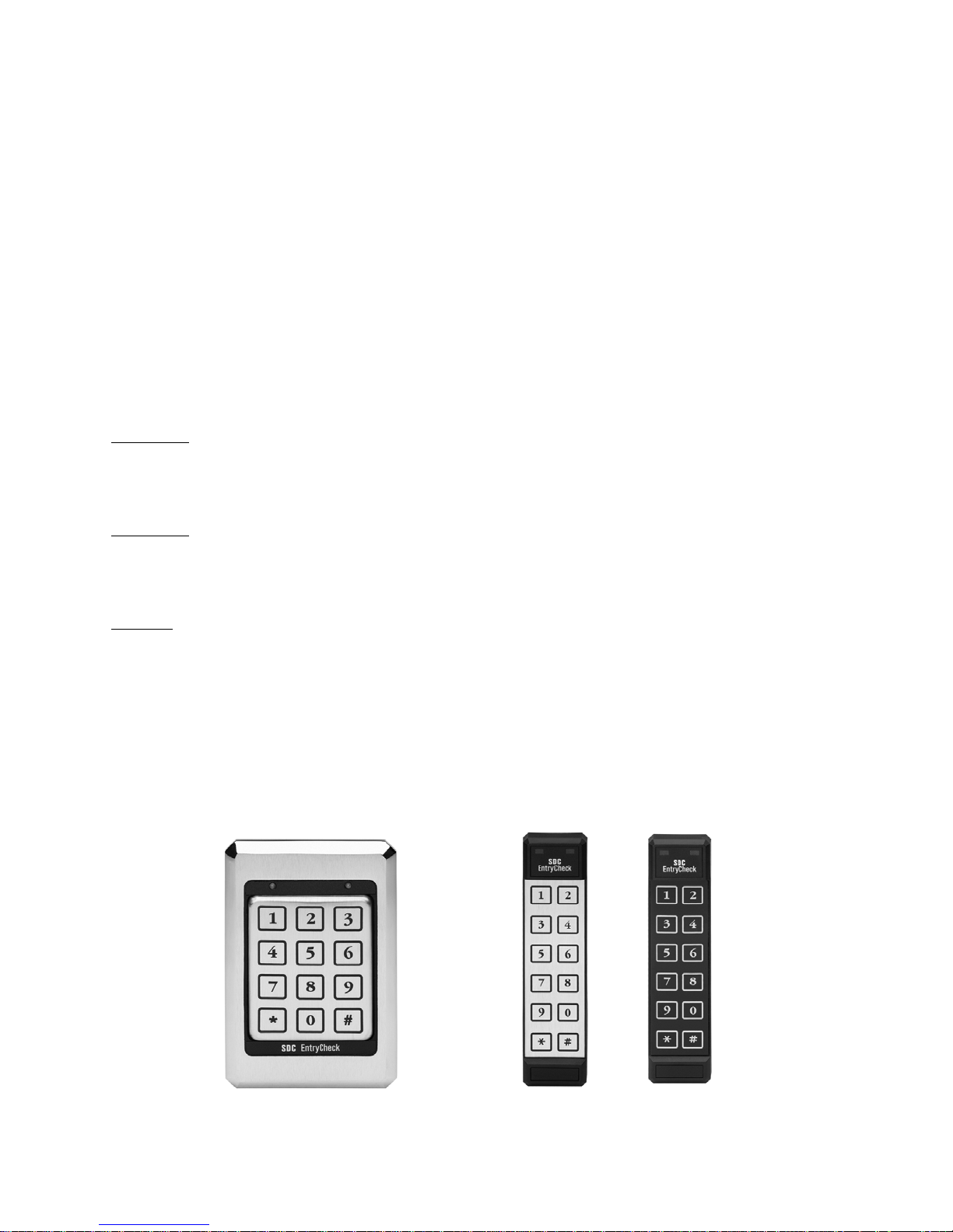
Operating temperatures can range from -40°C to +70°C (-40°F to 160°F). The 935 EntryCheck™ is
compatible with any of the following Keypad styles/configurations:
KP-40U
P:\INSTALLATION INST\ACCESS CONTROL\INST-935.vsd 0505 Page 4
KP-30U
KP-30Y
Page 5
PREPARING FOR INSTALLATION
SYSTEM COMPONENTS
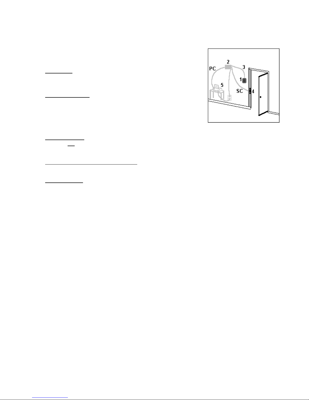
There are four primary components and one optional component to be
installed:
The Keypad should be mounted on the wall adjacent to the door. It
should be on the same side as the door strike and about 4 feet
above the floor.
The Control Module
power source. Typically the control module is hidden in a false
ceiling or closet. The control module must be located in an
environmentally controlled area where the temperature remains
between
–40C and + 49C (-40 F and +125 F.)
The Wiring Cable
important not to locate the cable adjacent to any wiring that carries
line voltage.
The Electric Strike/Other Locking Device (not included) connects to the 935 EntryCheck™ Main
Relay output. See Appendix B Typical Wiring Diagrams
A Parallel Printer
to have a “dedicated” printer, we suggest connecting a printer cable (PC) to the 935, which leads to
a nearby parallel printer. Anytime you need to print anything from the 935, simply connect the
printer cable to the printer.
Note: Many printers require bi-directional communication. The 935 may not work with these kinds of
printers. We suggest a basic dot matrix printer (i.e. Epson LX-300).
should be mounted inside the building near a
Typical Installation
connects the keypad to the control module. It is
(optional) – connects directly to the 935 EntryCheck™. Although it is not necessary
THE INSTALLATION PROCEDURE
REQUIRED TOOLS
You will need the following tools:
Medium sized, Phillips head screwdriver
1/8” standard screwdriver
Drill
7/8” or 1” (25mm) drill bit
1/2” (16mm) drill bit
5/32” (4mm) drill bit (For 12-Pad 3x4)
3/16” (6mm) drill bit (For Thinline 2x6)
PREPARE THE KEYPAD FOR INSTALLATION
There are different procedures for mounting each Keypad. Locate the Keypad part number on the back
of the Keypad and follow appropriate mounting instructions.
P:\INSTALLATION INST\ACCESS CONTROL\INST-935.vsd 0505 Page 5
Page 6

MOUNTING INSTRUCTIONS KP40U PAD 3X4
The 3x4 keypad is designed to mount to a single gang switchbox or on a wall, pedestal or any flat
surface of at least 3 ½ by 5 ¼”. The composition of the mounting surface will determine the fastening
method required. If mounting to a surface other than a switchbox:
1. Select a flat surface (3 ½” by 5 ¼”) near the door where you wish to install the keypad.
2. Drill the large hole for the Keypad connector using a ⅞” (25mm) drill bit.
3. Place the connector on the back of the keypad in the large hole. Mark the keypad mounting holes.
4. Drill clearance holes in accordance with fastening method used. (If mounting to wood, drill small
pilot holes and use #6 flat head wood screws provided. If mounting to metal, drill two
5
/32" clearance
holes for #6 flat head machine screws provided.)
5. Do NOT mount the keypad at this time.
6. Proceed to Install the Wiring Cable.
MOUNTING INSTRUCTIONS KP-30U AND KP-30Y 2X6:
The KP-30 is designed for mullion mount applications. It can also be mounted on a wall, pedestal or
any flat surface of at least 1 ¾” by 7”. The composition of the mounting surface will determine the
fastening method required:
1. Select a flat surface (1 ¾” by 7") near the door where you wish to install the keypad.
2. Using a Thinline template, mark location of holes.
3. Drill the large hole using a ⅞” or 1” (25mm) drill bit.
4. Place the connector on the back of the keypad in the large hole to verify that the mounting holes are
aligned. Make adjustments if necessary.
5. Drill mounting holes in accordance with fastening method used. (If mounting to plaster, use the #8
wood screws and plastic anchors included with the KP-30)
6. Do NOT mount the keypad at this time.
7. Proceed to Install the Wiring Cable.
P:\INSTALLATION INST\ACCESS CONTROL\INST-935.vsd 0505 Page 6
Page 7

INSTALL THE WIRING CABLE
1. Drill a ½” hole in the inside wall or ceiling where you want the cable to come through.
2. Pull the cable through the hole so the connector end goes to the keypad. Route it so there is minimal
cable at the keypad.
Note: Supplied with the system is a 6-conductor cable designed to connect the keypad to the control
module. You will also need a three-conductor cable (not included) to connect the control module to
the electric strike or other locking device.
MOUNT THE KEYPAD
1. Attach the wiring connector to the Keypad.
2. Attach the Keypad to the wall.
3. Do NOT mount the Keypad labels until the system is tested.
PREPARE THE DOOR FOR THE ELECTRIC STRIKE
Follow these instructions only if you are using an electric strike to unlock the door. If you are using the
main relay to activate a garage door, automatic gate, etc., skip this section. The new electric strike
should be checked to verify compatibility with existing door hardware prior to installation.
1. Remove existing strike.
2. Follow directions included with the strike for preparing the doorjamb.
3. Do NOT mount the strike at this time.
INSTALLING THE CONTROL MODULE
1. Connect the Wiring Cable to Terminal Strip “A” following the color sequence on the circuit board.
(See Appendix A Circuit Board Layout – Page 27)
2. For AC Input
Note: If using an external AC Adaptor, connect low voltage AC output to the 12-24V input screws.
Connect ground wire to one of the “EARTH GROUND” screws on Terminal Strip “A”. Plug adapter into
a grounded (three terminal) receptacle.
For DC Input
DC+”. Make sure the polarity is correct.
IMPORTANT: The “EARTH GROUND” screw terminal on Terminal Strip “A” should be connected to a
true earth ground for proper system protection and operation.
: Connect 12 to 24 Volts AC to Terminal Strip “B” to screws marked “12-24V AC IN”.
: Connect 12 to 24 Volts DC to Terminal Strip “B” to screws marked “POWER TAP/GND
P:\INSTALLATION INST\ACCESS CONTROL\INST-935.vsd 0505 Page 7
Page 8

CONNECTING THE LOCKING DEVICE
Connect the electric locking device to Terminal Strip “B” as outlined in the Typical Wiring Diagram
(Appendix B – Page 28). Any 3 conductor, 22 gauge wire can be used to connect the Control Module to
the Locking Device.
Included in the spare parts kit are two MOV’s (metal oxide varistor). The function of the MOV is to
absorb any inductive kickback from the locking device, protecting the circuit board. The MOV’s should
be installed as close to the electric lock as possible. See Typical Wiring Diagram (Appendix B – Page
28). If switching voltages higher than 36V, do not use the MOV. To provide proper grounding, connect
rd
the 3
wire from the body of the locking device to the “EARTH” screw on Terminal “A”
SYSTEM HARDWARE SETUP
REMOTE BY-PASS
In some cases, it may be necessary to control the door from a remote area such as a security station or
reception desk. The 935 EntryCheck
override. This can be accomplished by connecting a normally open
™
provides for a Remote By-Pass (Exit Switch) or Keypad
switch to the “REMOTE” and “GND”
screw terminals on the circuit board (See Appendix A – Page 27). When the Remote By-Pass switch is
depressed, the contact bypasses the Keypad and activates the main relay. The relay is activated for
the same time length as the programmed Door Open Time (See Programming System Setup for Door
Open Time – Page 10)
ANTI-TAILGATING
Some security applications require stricter door monitoring. Anti-tailgating can be accomplished by
installing a normally closed door monitor switch to the “DOOR MONITOR” and “GND” screw terminals
on the circuit board (See Appendix A – Page 27). This switch may be the output of a latch monitor
switch, a monitor maglock or an alarm switch that senses door movement. When this switch opens, it
will relock the door.
Note: If a door monitor switch is NOT used, you must jump the “MONITOR” screw terminals with the
factory installed wire.
BATTERY BACKUP
Battery backup is NOT required for User Code retention, however, you may wish to connect a SDC
Power Supply with battery backup to provide operation during a power interuption.
P:\INSTALLATION INST\ACCESS CONTROL\INST-935.vsd 0505 Page 8
Page 9

OVERVIEW OF SYSTEM PROGRAMMING
Once the 935 EntryCheck™ has been installed, the system is ready for programming. Before
proceeding with actual programming, we recommend you review the Suggested Initial Programming
Steps, System Defaults, System Options and the System Programming Commands & Feedback. We
suggest connecting a parallel printer directly to the 935 to verify programming.
Step
1
2
3
4
5
6
7
8
9
10
Description
Review System Defaults
Review System Setup
Make Changes in System Setup (Print to Verify)
Program the Time Clock (Print to Verify)
Program Holiday Schedule (Print to Verify)
Review Preprogrammed User Groups
Construct User Groups Configuration
Modify User Groups as needed (Print to Verify)
Construct a list of Individual Users, Codes and User Groups
Program Individual Users (Print to Verify)
System Option
Master Code
Door Open Time
Latching
Use of Duress Codes
2nd Relay
3rd Relay
Automatic Line Feed (ALF)
Daylight Savings Time (DST)
Time Clock Setting*
Default
1 2 3
5 Seconds
OFF
OFF
Auxiliary Controller for 5 seconds
CCTV/Light for 30 seconds
ON
ON
Wed 01/01/1999 00:00:00
Page
9
10
13
16
17
18
30
19
29
22
*Time Clock Setting Note
system is shipped from the factory in a “suspended clock” mode. The Time Clock will remain suspended
with the default setting until the Time Clock is properly set through system programming (page 20).
Failure to set the clock may cause “Access Denied” for Individual Users and the Default Time Clock
setting in the Audit Trail Date and Time stamp.
P:\INSTALLATION INST\ACCESS CONTROL\INST-935.vsd 0505 Page 9
: In order to preserve the internal battery life of the 935’s Time Clock, the
Page 10

THE MASTER CODE
SYSTEM SETUP
Knowledge of the Master Code is the highest privilege granted to a user of the 935 EntryCheck
™
system. There is only one Master Code, which is used to gain access to all programming areas
including System Setup. Typically only the facilities manager or security director should have access
to this code. The default Master Code, “1,2,3”, can be used for initial programming but should be
changed to a unique 3 to 8 digit code. The Master Code is reprogrammed through system setup.
Note
: If you forget the Master Code, locate the control module and remove the cover. Verify that the 5
dip switches are in the OFF position. Press “PGM SW” for at least 3 seconds. You will hear a double
beep at the keypad. Proceed to System Setup, Step 3 to change the Master Code (page 10).
Important:
If you set all 5 dip switches in the ON position and press “PGM SW”, this completely
erases the memory and restores system defaults!!!)
DOOR OPEN TIME / MAIN RELAY OUTPUT TIME
The Door Open Time refers to the length of time the door will remain unlocked following the entry of a
valid User Code. Although the default is set for 5 seconds, this setting can be changed to any value
between 01 and 99 seconds. See Programming System Setup (page 13-15).
LATCHING
There are three options for latching the door open or closed for extended periods of time. Latching
Authorization is determined in each User Group.
Off – Set as the default, this prevents latching.
1. Manual – This allows any authorized user to manually latch the door open (unlocked) or closed
(locked) indefinitely. If the 935 EntryCheck™ is set to Manual, latching is activated by entering
“1#” following entry of an authorized user code. Entering “0#” following an authorized code will
deactivate latching.
2. Timed – This allows any authorized user to latch the door open until a predetermined time of day
at which point the door will automatically latch closed. Entering “1#” following entry of an
authorized code will activate timed latching. Entering “0#” following entry of an authorized code
will deactivate timed latching.
DURESS CODES
The 935 EntryCheck™ can be configured to allow the use of Duress Codes. In emergency situations,
users who are forced to open the door against their will can use their Duress Code to open the door as
usual. In addition, if the 2
activate the alarm output. (The alarm output would typically be wired to a guard station or other
monitoring service that could respond to the emergency). If used, the Duress Code is the User Code
with the last digit increased by 1. For example: If your User Code is 3 3 3, your Duress Code is 3 3 4. If
your User Code 5 6 9, your Duress Code is 5 6 0.
Important:
If you wish to use the Duress Code Option, it must be set ON prior to any Individual User
Programming!!!
nd
Relay is configured to control the Internal Alarm, a duress code will also
P:\INSTALLATION INST\ACCESS CONTROL\INST-935.vsd 0505 Page 10
Page 11

2nd RELAY
The 2nd Relay can be configured as one of the following:
Controlling an External Alarm – The 2nd Relay can be configured to either enable/disable or shunt an
existing alarm system for 01 to 99 seconds.
Internal Alarm
– The 2nd Relay can be used to monitor and report events such as duress, break-in,
door ajar and tamper. In order to detect these occurrences, you will need to install a door monitor
switch or latch monitor switch.
Controlling an Auxiliary Device
momentary output. The 2nd Relay can be programmed to provide a momentary output for 01 to 99
seconds or a manual ON/OFF output. The 2
– By default, the 2nd Relay is configured to provide a 5 second
nd
Relay is activated by entering “3#” following entry of
an authorized User Code. Entering “2#” following entry of an authorized code will deactivate the 2
Relay.
3rd RELAY
The 3rd Relay can be configured as one of the following:
1. Activate a Doorbell
included with the 935 EntryCheck
“#” will activate the relay.
Note
: Do not precede the “#” with any other keystrokes.
2. Controller for a Closed Circuit TV (CCTV) or External Light
activate at the first touch of the Keypad and remain ON for a 30 second time interval after the last
keypad touch. This time interval can be adjusted from 01 to 99 seconds.
– The 3rd Relay can be used trigger a 1 second output to activate a doorbell (not
™
). If the 3rd Relay is programmed for a doorbell, simply entering
– By default, the 3rd Relay is configured to
nd
3. Controlling an Auxiliary Device
– The 3rd Relay can be configured to control an auxiliary device of
your choice. In this case the 3rd Relay can provide a momentary output for 01 to 99 seconds or a
manual ON/OFF output. The 3rd Relay is activated by entering “5#” following entry of an authorized
User Code. Entering “4#” following entry of an authorized code will deactivate the 3rd Relay.
AUTOMATIC FEED LINE
When connecting a parallel printer to the 935 EntryCheck
to advance the printer paper to the next line. In other cases, some printers have a built-in command to
automatically provide this line feed. If necessary, the printer line feed can be set ON or OFF. See
System Setup (page 15).
P:\INSTALLATION INST\ACCESS CONTROL\INST-935.vsd 0505 Page 11
™
, most printers require an automatic line feed
Page 12

DAYLIGHT SAVINGS TIME
By default, the 935 EntryCheck™ is configured to automatically adjust the time clock twice each year for
daylight savings time. The 935 makes the adjustment at 2 a.m. In areas where this adjustment is not
necessary, this option can be turned off. To adjust the setting for automatic Daylight Savings Time
adjustment, proceed to System Setup (page 15).
Notes to Remember When Programming
1. Knowledge of the Master Code is required to program System Setup. Knowledge of the Master
Code or an authorized User Code is required to program Users.
2. Each User/User Code is programmed into one of the 499 User ID’s (or User Locations). See
Appendix C for a User Programming Form.
3. User Codes can vary in length from 3 to 8 digits.
4. The # or key cannot be used as part of a User Code.
5. The system does not allow you to program duplicate codes.
6. The “#” key is used as an “Enter” key in programming and normal operation.
7. The “ ” command is used to complete a programming sequence or to reset the system back to
normal operation. If you are distracted or interrupted, while in the programming mode or in normal
operation, enter to reset the system back to normal operation. Depending on the level of
programming, you may need to enter several times until neither LED is flashing.
*
**
**
Key/Feedback
Double Beep
Triple Beep
Long Steady Beep
System Option
Begin Programming Sequence
*
Clear/Reset or Complete and Exit Programming
**
#
“Enter” Key
Entry accepted and more data needed
Completion of Programming Step
Error
RESETTING THE SYSTEM
In certain cases you may want to erase all programmed user codes and restore system defaults. To
perform this procedure, locate the control module, remove the cover and set all 5 dip switches in the ON
position. Press the “PGM SW” switch for at least 3 seconds. The keypad will beep rapidly 5 times
indicating the memory has been cleared. Once the system has been reset, set the dip switches to the
OFF position.
Important:
memory is cleared, all programmed Users (codes) are erased, the audit trail buffer is cleared, User
Groups and System Setup options are restored to the factory default settings!!!
P:\INSTALLATION INST\ACCESS CONTROL\INST-935.vsd 0505 Page 12
This procedure completely erases the memory and restores system defaults!!! Once the
Page 13
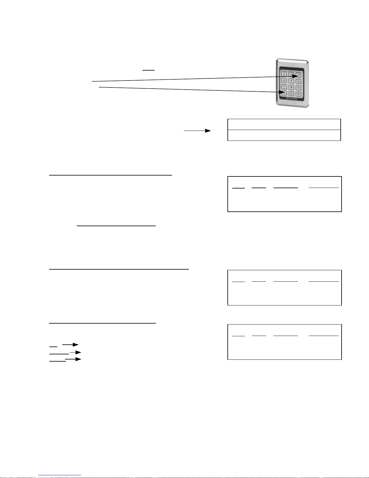
PROGRAMMING SYSTEM SETUP
The 935 EntryCheck™ System Setup can only be modified if you know
the Master Code. When the system is initially setup, the default
system settings should be reviewed prior
to other programming.
1. Enter * 3
2. Enter the Master Code followed by #
Example: 3 123 #
This opens programming and causes
*
Red LED Green LED
*
Slow Flash Solid
3. Proceed to one of the following options which requires programming:
To Change the Master Code (Default: 1,2,3)
A) Enter 1#
B) Enter the New Master Code
followed by #
C) Re-enter the New Master Code, followed by #
D) Return to Step 3 or enter to exit programming.
Note: If you forget the Master Code
installed in a secured area within 15’ of the keypad.) Remove the cover, locate and press
the “PGM SW” switch on the circuit board for 3 seconds (make sure the 5 dip switches are
OFF). This will take you to Step 3 of Programming System Setup. Once you press the
program switch, you have 1 minute to begin the program sequence.
**
, locate the control module. (The control module is typically
Step
Keypad Status after Step Completion
Green LED
Slow Flash
Solid
A)
B)
Beep
Double
Triple
Red LED
Slow Flash
Slow Flash
Setting the Door Open Time (Default: 5 Seconds)
A) Enter 2 #
B) Enter the desired Door Open
Time in two digits (01 to 99 seconds), followed by #
Example: 2 # 1 5 # Set a 15 second Door Open Time
C) Return to Step 3 or enter to exit programming.
Setting Latching Option (Default: Off)
A) Enter 3 #
B) Select desired latching option
Off
Enter 9900, followed by #
Manual Enter 9901, followed by #
Timed Enter the desired time (hour/minute) in four
digits (24 hour), followed by #
Example: 3 # 1 7 0 0 # Sets timed latching at 5:00 p.m.
C) Return to Step 3 or enter to exit programming.
**
**
Step
A)
B)
Step
A)
B)
Beep
Double
Triple
Beep
Double
Triple
Red LED
Slow Flash
Slow Flash
Red LED
Slow Flash
Slow Flash
Green LED
Slow Flash
Solid
Green LED
Slow Flash
Solid
P:\INSTALLATION INST\ACCESS CONTROL\INST-935.vsd 0505 Page 13
Page 14
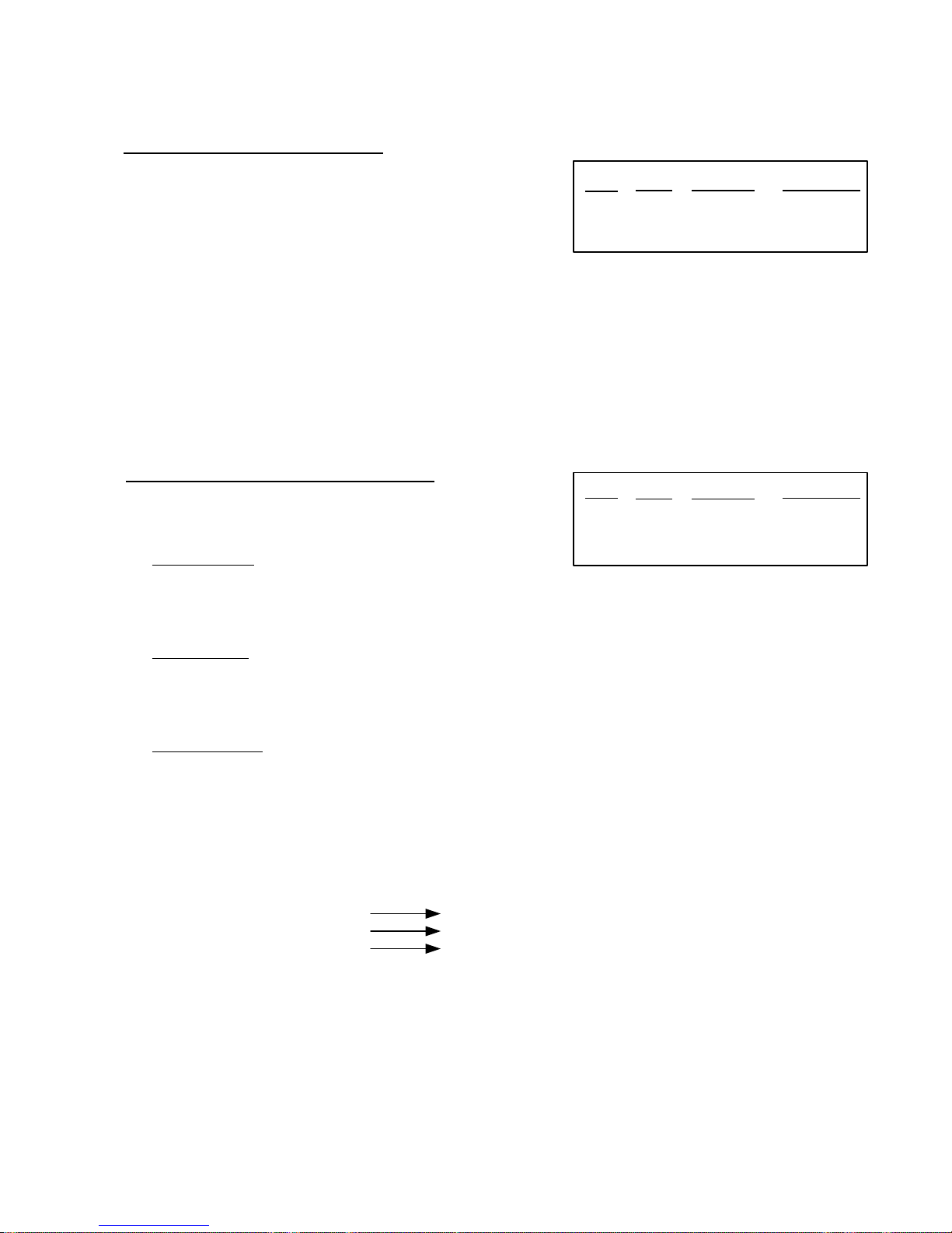
PROGRAMMING SYSTEM SETUP (Continued)
Keypad Status after Step CompletitionUsing Duress Codes (Default: OFF)
A) Enter 4 #
A)
B)
A)
ii.
Beep
Double
Triple
Beep
Double
i.
Double
Triple
B) Enter 0 # to turn OFF
use of Duress Codes
--or –
Enter 1 # to turn ON use of Duress Codes
C) Return to Step 3 or enter to exit programming.
Important Note: Duress Code Option must be determined and programmed prior to User
Programming!!! You should hear a triple beep after completing step B indicating the use of duress
codes has been successfully reprogrammed. A long steady beep indicates an error (i.e. there may be
individual user codes already programmed into the system. These codes must all be deleted in order
to set duress option to ON.)
Configuring 2nd Relay (Default: Aux 5 sec)
A) Enter 5 #
B) Select one of the following:
External Alarm
I. Enter 1 #
II. Enter the desired Alarm Shunt Output Time (01 - 99 seconds),
followed by #
**
Step
Step
Red LED
Slow Flash
Slow Flash
Red LED
Slow Flash
Slow Flash
Slow Flash
Green LED
Slow Flash
Solid
Green LED
Slow Flash
Fast Flash
Solid
Internal Alarm
I. Enter 2 #
II. Enter the desired Door Ajar Time in two digits (01-99 seconds),
followed by #
Auxiliary Device
I. Enter 3 #
II. Enter the momentary output time in two digits (01-99 seconds),
followed by #
-- or - Enter 0 0 to set the auxiliary device for Manual Operation (ON/OFF),
followed by #
Examples: 5 # 1 # 1 5 # Set External Alarm Shunt Option for 15 seconds
5 # 2 # 1 0 # Set Internal Alarm with a 10 second Door Ajar Time
5 # 3 # 0 0 # Set Auxiliary Device with Manual Operation
C) Return to Step 3 or enter to exit programming.
**
P:\INSTALLATION INST\ACCESS CONTROL\INST-935.vsd 0505 Page 14
Page 15
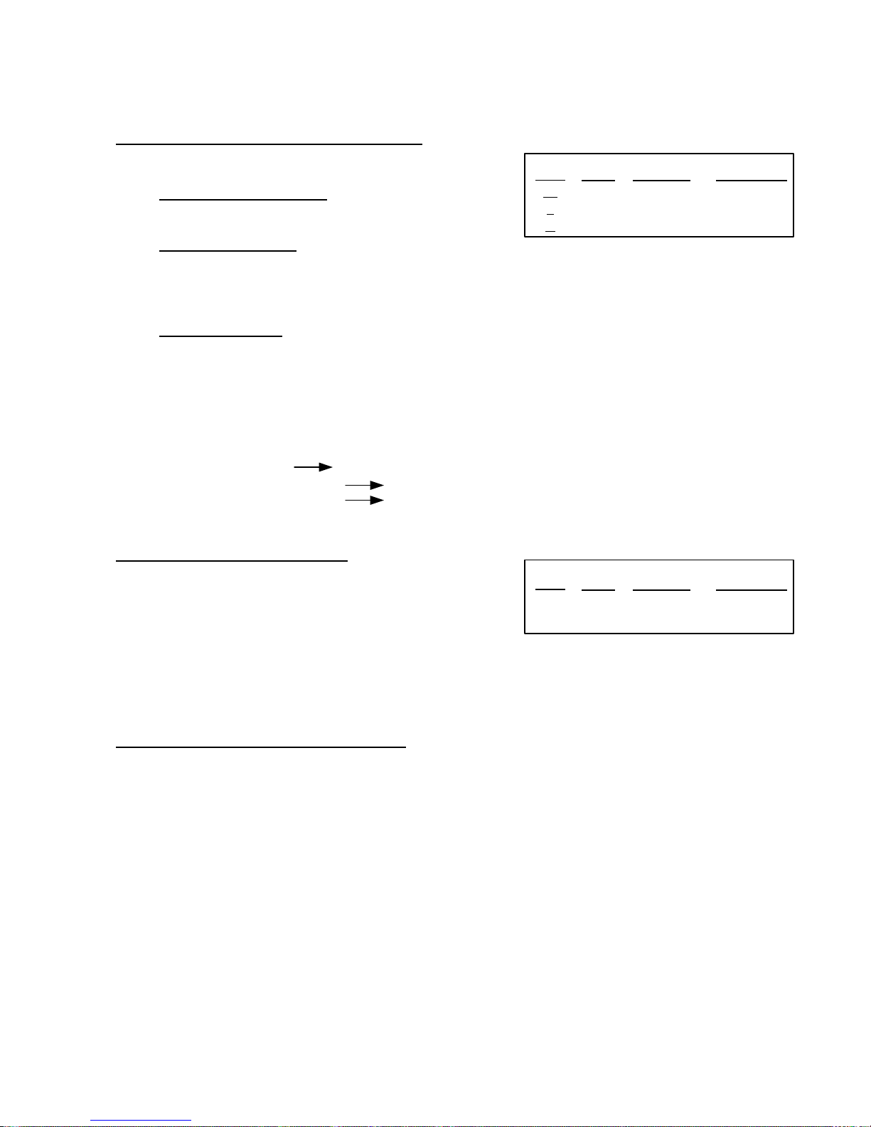
PROGRAMMING SYSTEM SETUP (Continued)
Configuring 3rd Relay (Default: CCTV 30 Sec)
A) Enter 6 #
B) Select one of the following:
Doorbell (1 second output)
I. Enter 1 #
CCTV / External Light
I. Enter 2 #
II. Enter the desired On Time in two digits (01-99 seconds),
followed by #
nd
2
Auxiliary Device
I. Enter 3 #
II. Enter the desired momentary output time in two digits (01-99 seconds) followed by #
-- or --
Enter 0 0 to set the auxiliary device for Manual Operation (ON/OFF), followed by #
C) Return to Step 3 or enter to exit programming.
Examples: 6 # 1 # Set Doorbell Option
6 # 2 # 2 5 # Set CCTV/Light with a 25 second On Time
6 # 3 # 0 0 # Set Auxiliary Device with Manual Operation
**
Keypad Status after Step Completition
Step
A)
ii.
Beep
Double
i.
Double
Triple
Red LED
Slow Flash
Slow Flash
Slow Flash
Green LED
Slow Flash
Fast Flash
Solid
Automatic Line Feed (Default: ON)
A) Enter 7 #
B) Enter 0 # to turn OFF
-- or --
Enter 1 # to turn ON
C) Return to Step 3 or enter to exit programming.
Note: The printer line feed setting should only be adjusted if you encounter printer problems
(i.e. An unnecessary extra line or printing on the same line).
Daylight Savings Time “DST” (Default: ON)
A) Enter 8 #
B) Enter 0 # to turn OFF
-- or --
Enter 1 # to turn ON
C) Return to Step 3 or enter to exit programming.
4. To Print System Setup, enter 9 #
5. Enter to complete programming sequence and reset the system to normal operation.
**
**
**
Step
A)
B)
Beep
Double
Triple
Red LED
Slow Flash
Slow Flash
Green LED
Slow Flash
Solid
P:\INSTALLATION INST\ACCESS CONTROL\INST-935.vsd 0505 Page 15
Page 16
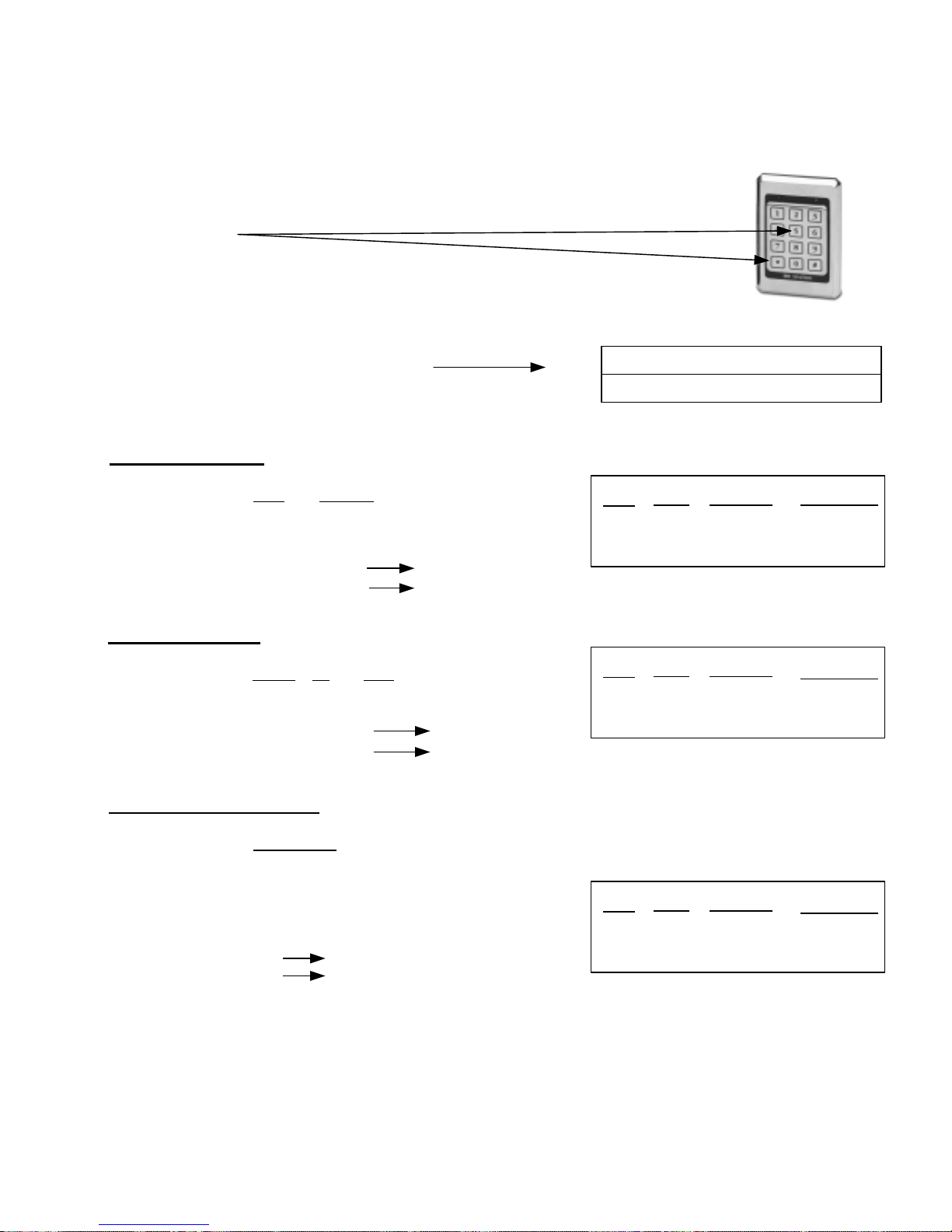
PROGRAMMING THE TIME CLOCK
Authorized users (master code holder or any user assigned to a User Group
given the authorization to program users) can program the 935 EntryCheck
time clock from the keypad.
1. Enter 5
*
™
’s
2. Enter the Master Code (or a User Code who is authorized to program), followed by #
Example: 5 123 #
This opens programming and causes
*
Red LED Green LED
Slow Flash Solid
3. Proceed to any of the following which requires programming:
To program the Time
A) Enter 1#
B) Enter the current hour and minutes in four digits (24 hour
clock), followed by #
C) Return to Step 3 or enter to exit programming.
Examples: 1 # 1 0 0 0 # 10:00 a.m.
1 # 1 5 1 5 # 3:15 p.m.
**
Keypad Status after Step Completion
A)
B)
Beep
Double
Triple
Step
Red LED
Slow Flash
Slow Flash
Green LED
Slow Flash
Solid
To program the Date
A) Enter 2#
B) Enter the current month, day and year in six digits, followed by #
C) Return to Step 3 or enter to exit programming.
Examples: 2 # 0 2 0 5 0 5 # February 5
2 # 1 1 1 5 0 4 # November 15th, 2004
To program the Day of Week
A) Enter 3#
B) Enter the current day of week followed by #
C) Return to Step 3 or if you have completed programming the
time clock,
Enter to complete programming sequence and reset
system to normal operation.
Examples: 3 # 1 # Monday
**
3 # 6 # Saturday
**
th
, 2005
4. To Print current Time/Date/Day of Week, enter 9 #
5. Enter to complete programming sequence and reset the
**
system to normal operation
Step
A)
B)
Step
A)
B)
Beep
Double
Triple
Beep
Double
Triple
Red LED
Slow Flash
Slow Flash
Red LED
Slow Flash
Slow Flash
Green LED
Slow Flash
Solid
Green LED
Slow Flash
Solid
P:\INSTALLATION INST\ACCESS CONTROL\INST-935.vsd 0505 Page 16
Page 17
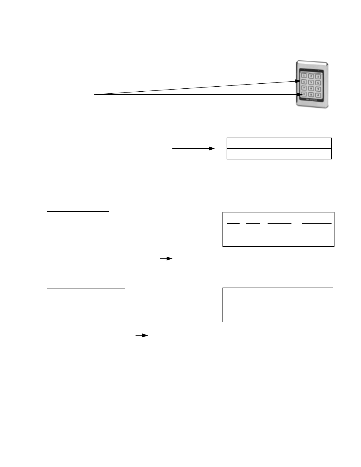
PROGRAMMING THE HOLIDAY SCHEDULE
The 935 EntryCheck
(master code holder or any user assigned to a User Group given the
authorization to program users) can program up to 32 holidays. Each User
Group is programmed to either authorize or prevent access on these scheduled
dates.
1. Enter 4
*
™
provides a 32-day holiday schedule. Authorized users
2. Enter the Master Code (or a User Code who is authorized to program),
followed by #
Example: 4 123 #
This opens programming and causes
*
Red LED Green LED
Slow Flash Solid
3. Proceed to any of the following which requires programming:
Adding a New Holiday
A) Enter 1#
B) Enter the holiday to add in four digits (month/day),
followed by #
C) To add an additional holiday, return to step B otherwise
enter and return to Step 3.
Example: 1 # 0 1 0 1 # 0 7 0 4 # Adds January 1
**
Keypad Status after Step Completion
A)
B)
Beep
Double
Triple
Step
st
and July 4th to the holiday schedule.
Red LED
Slow Flash
Slow Flash
Green LED
Slow Flash
Slow Flash
Deleting an existing Holiday
A) Enter 2#
B) Enter the holiday to delete in four digits
(month/day), followed by #
C) To delete an additional holiday, return to step B otherwise
enter and return to Step 3.
Examples: 2 # 1 1 2 6 # Deletes November 26
**
4. To Print the Holiday Schedule, enter 9 #
5. Enter to complete programming sequence and reset the system to normal operation.
P:\INSTALLATION INST\ACCESS CONTROL\INST-935.vsd 0505 Page 17
**
Red LED
Slow Flash
Slow Flash
A)
B)
Beep
Double
Triple
Step
th
from the holiday schedule.
Green LED
Slow Flash
Slow Flash
Page 18
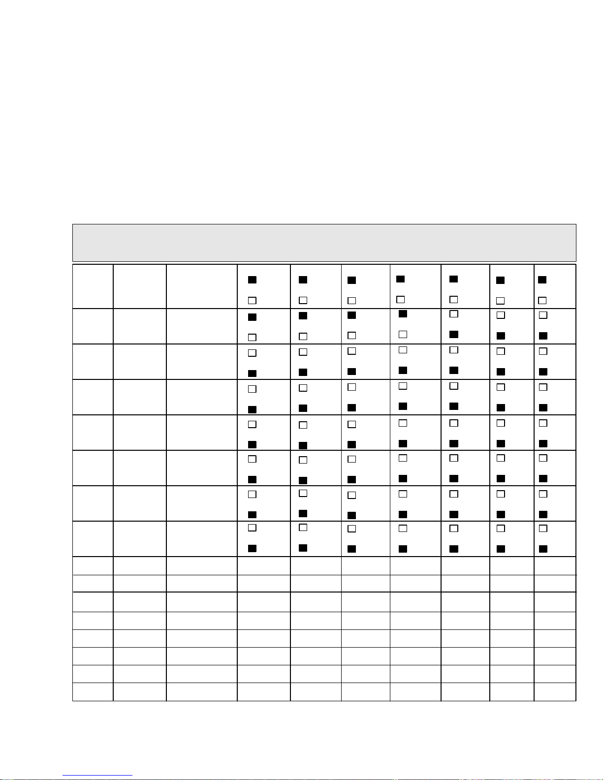
USER GROUPS
The 935 EntryCheck™ simplifies the process of programming users by providing 16 programmable User
Groups. Rather than assigning authorization options (i.e. latching, user programming and time zone
authorization) to each individual user, these authorizations are determined for each User Group. Individual
Users are then assigned to an appropriate User Group. Although these User Groups have been
preprogrammed with some typical authorization options, User Group authorizations can be modified to fit
your particular needs. (See Appendix D, page 30 for a User Group Configuration Worksheet)
Preprogrammed User Groups
User
Group
01
02
03
04
05
06
07
08
09
Days of
Entry
All 24 Hour
M, T, W,
TH, F
M, T, W,
TH, F
M, T, W,
TH, F
Sat &
Sun
24 Hour
Sat &
Sun
M, W,
F
T, TH
Times of
Entry
8am-
5pm
8am-
5pm
11pm-
7am
8am-
5pm
8am-
5pm
8am-
5pm
Latch
Yes
No
Yes
No
Yes
No
Yes
No
Yes
No
Yes
No
Yes
No
Yes
No
Temp
User
Yes
No
Yes
No
Yes
No
Yes
No
Yes
No
Yes
No
Yes
No
Yes
No
Delete
User
Yes
No
Yes
No
Yes
No
Yes
No
Yes
No
Yes
No
Yes
No
Yes
No
PGM
User
Yes
No
Yes
No
Yes
No
Yes
No
Yes
No
Yes
No
Yes
No
Yes
No
Relay
# 2
Yes
No
Yes
No
Yes
No
Yes
No
Yes
No
Yes
No
Yes
No
Yes
No
Relay
# 3
Yes
No
Yes
No
Yes
No
Yes
No
Yes
No
Yes
No
Yes
No
Yes
No
Holiday
Access
Yes
No
Yes
No
Yes
No
Yes
No
Yes
No
Yes
No
Yes
No
Yes
No
10
11
12
13
14
15
16
P:\INSTALLATION INST\ACCESS CONTROL\INST-935.vsd 0505 Page 18
Page 19
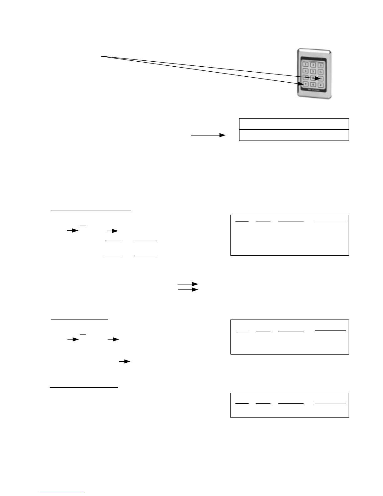
MODIFYING USER GROUPS
1. Enter 9
*
2. Enter the Master Code (or a User Code who is
authorized to program),
followed by #
Example: 9 123 #
This opens programming and causes
*
Red LED Green LED
Slow Flash Solid
3. To Modify a Group, enter the User Group
number in two digits (01-16),
followed by #.
Example: 0 2 # Select User Group 2
4. Proceed to any of the following which requires programming:
Time Zone – Add or Modify
A) Enter 1#
B) Select all similar days
(1 Mon, 2 Tue), followed by #
C) Enter start time hours
(24 hour time) followed by #
D) Enter stop time hours
(24 hour time) followed by #
E) To program additional days, return to step A otherwise return to Step 4.
and minutes in four digits
and minutes in four digits
Keypad Status after Step Completion
Step
A)
B)
C)
D)
Beep
Double
Double
Double
Triple
Red LED
Slow Flash
Slow Flash
Slow Flash
Slow Flash
Green LED
Fast Flash
Fast Flash
Fast Flash
Slow Flash
Examples: 1 # 1 5 # 0 8 3 0 # 1 7 0 0 # Mon & Fri Start: 8:30a.m. Stop: 5:00 p.m.
1 # 2 # 0 0 0 0 # 0 0 0 0 # Tuesday, 24 Hours
Time Zone – Delete
A) Enter 2#
B) Select all days to delete
(1 Mon, 2 Tue), followed by #
C) Return to Step 4
Examples: 2 # 1 # Deletes Monday’s Time Zone Authorization.
Latching Authorization
A) Enter 3 0 # to prevent latching
-- or --
Enter 3 1 # to authorize latching
B) Return to Step 4
Step
A)
B)
Step
A)
Beep
Double
Triple
Beep
Triple
Red LED
Slow Flash
Slow Flash
Red LED
Slow Flash
Green LED
Slow Flash
Slow Flash
Green LED
Slow Flash
P:\INSTALLATION INST\ACCESS CONTROL\INST-935.vsd 0505 Page 19
Page 20
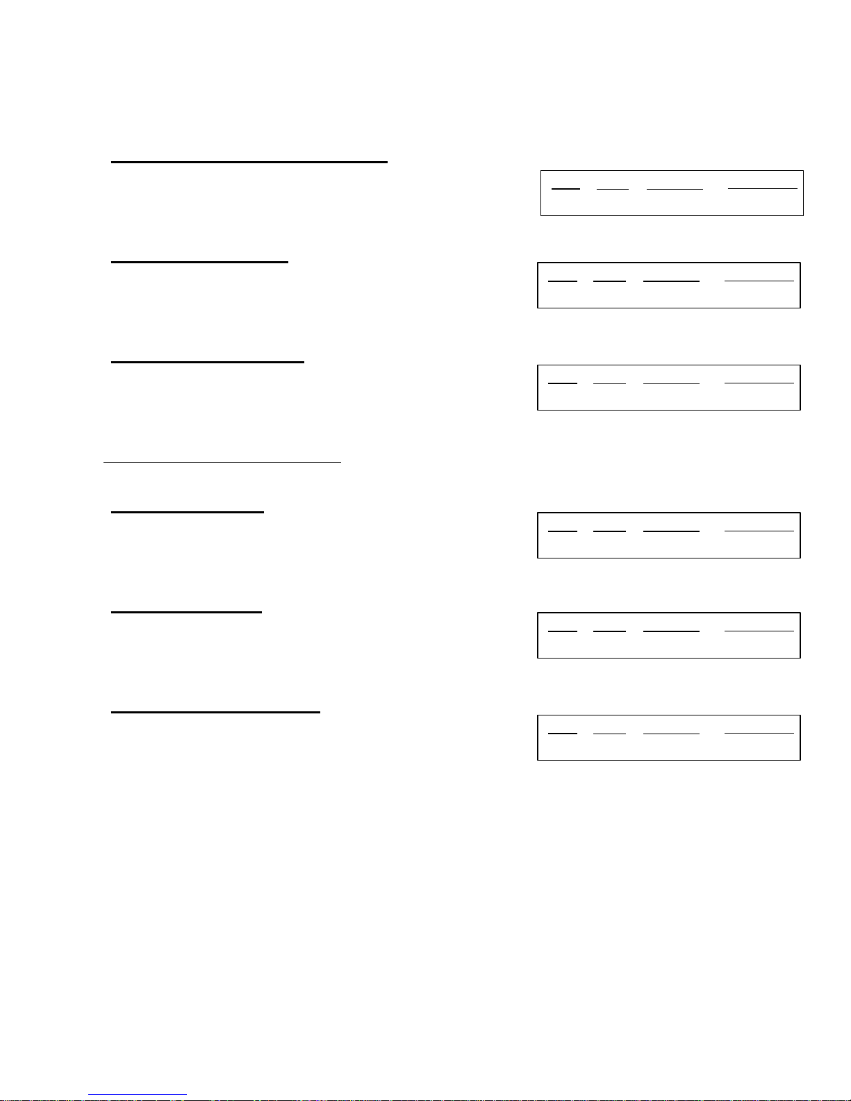
MODIFYING USER GROUPS (Continued)
Program a Temporary Code Authorization
A) Enter 4 0 # to prevent Temp Code Programming
-- or - Enter 4 1 # to authorize Temp Code Programming
B) Return to Step 4
Delete Users Authorization
A) Enter 5 0 # to prevent Deletion of Users
-- or - Enter 5 1 # to authorize Deletion of Users
B) Return to Step 4
Program Users Authorization
A) Enter 6 0 # to prevent User Programming
-- or - Enter 6 1 # to authorize User Programming
B) Return to Step 4
Notes on Program Users Authorization
: Authorization to Program Users also provides
authorization to Delete Users and Program Temporary Users
nd
2
Relay Authorization
A) Enter 7 0 # to prevent 2nd Relay Operation
-- or - Enter 7 1 # to authorize 2nd Relay Operation
B) Return to Step 4
Keypad Status after Step Completion
Step
A)
Step
A)
Step
A)
Step
A)
Beep
Triple
Beep
Triple
Beep
Triple
Beep
Triple
Red LED
Slow Flash
Red LED
Slow Flash
Red LED
Slow Flash
Red LED
Slow Flash
Green LED
Slow Flash
Green LED
Slow Flash
Green LED
Slow Flash
Green LED
Slow Flash
rd
3
Relay Authorization
A) Enter 8 0 # to prevent 3rd Relay Operation
-- or - Enter 8 1 # to authorize 3
rd
Relay Operation
B) Return to Step 4
Holiday Schedule Authorization
A) Enter 9 0 # to prevent access on holidays
-- or - Enter 9 1 # to authorize access on holidays
B) Return to Step 4
5. Once all changes have been made for this User Group, enter .
**
Step
A)
Step
A)
Beep
Triple
Beep
Triple
Red LED
Slow Flash
Red LED
Slow Flash
Green LED
Slow Flash
Green LED
Slow Flash
P:\INSTALLATION INST\ACCESS CONTROL\INST-935.vsd 0505 Page 20
Page 21

5. Printing User Group(s)
A) Enter 9 #
MODIFYING USER GROUPS (Continued)
Keypad Status after Step Completion
Step
A)
B)
Beep
Double
Triple
Red LED
Slow Flash
Slow Flash
Green LED
Slow Flash
Solid
B) To print a specific User Group
in two digits (01-16), followed by #
-- or - To print all User Groups
C) To print another User Group, return to step A)
Examples: 9 # 0 1 # To print authorizations and all users assigned to User Group 1
9 # 0 0 # To print authorizations only for all 16 User Groups
Notes on Printing User Group(s)
are printed followed by a list of all Individual Users currently assigned to the group. When all
Groups are selected to print, only group authorizations are printed,
6. To modify an additional User Group, return to step 3. Otherwise enter to complete
programming sequence and reset the system to normal operation.
, enter the User Group Number
, enter 0 0, followed by #
: When a specific User Group is selected to print, group authorizations
User
**
P:\INSTALLATION INST\ACCESS CONTROL\INST-935.vsd 0505 Page 21
Page 22
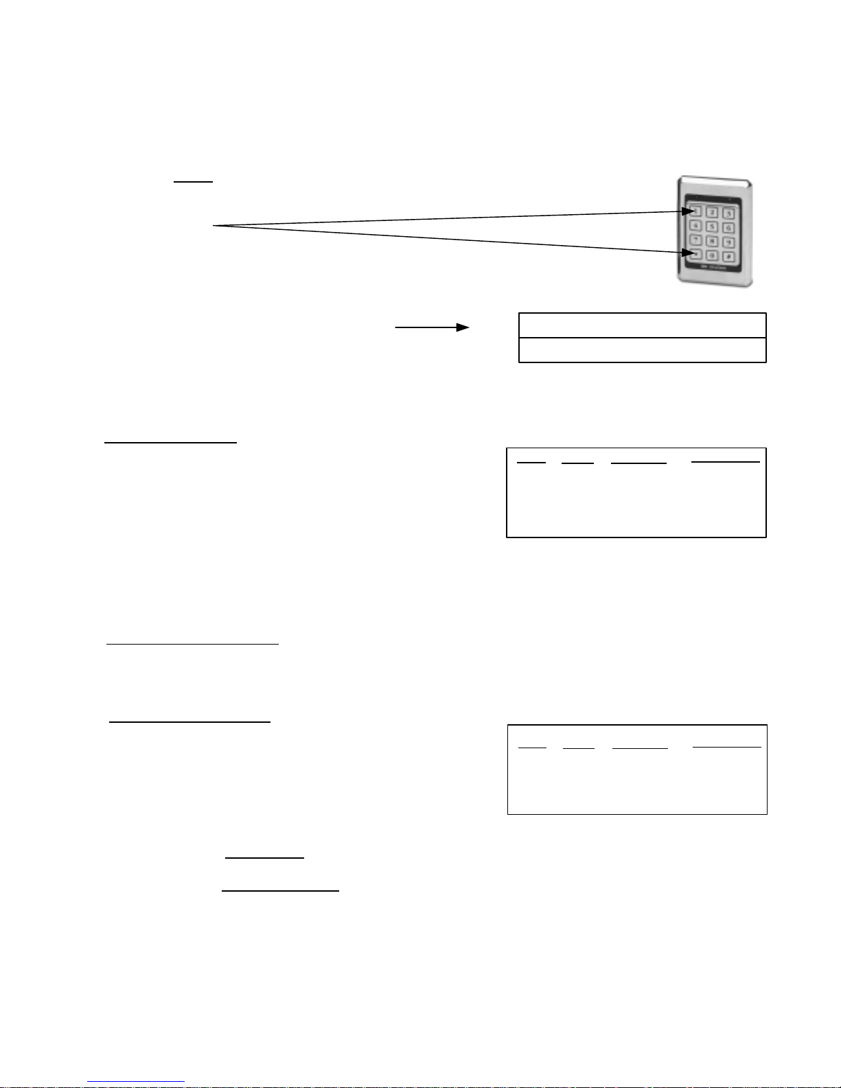
PROGRAMMING INDIVIDUAL USERS
Authorized users (master code or any user assigned to a User Group given the
authorization to program users) can program users directly from the keypad. Each
Individual User is assigned to one of 16 User Groups. Review System Setup and set the
Time Clock before
programming individual users.
1. Enter 1
*
2. Enter the Master Code (or a User Code who is authorized to program), followed by #
Example: 1 123 #
This opens programming and causes
*
Red LED Green LED
Slow Flash Solid
3. Proceed to any of the following which requires programming:
Adding a New User
A) Enter 1#
B) Enter the User ID (1 to 499), followed by #
C) Enter the User Code/PIN
(3 - 8 digits), followed by #
D) Enter the desired User Group number in two digits (01-16),
followed by #
E) To program an additional User, return to Step B.
F) If no more Users are to be added, enter and return to Step 3
or if you have completed all User Programming, enter a second
time to complete programming sequence and reset system to normal operation.
**
Keypad Status after Step Completion
Step
A)
B)
C)
D)
Beep
Double
Double
Double
Triple
Red LED
Slow Flash
Slow Flash
Slow Flash
Slow Flash
Green LED
Slow Flash
Fast Flash
Fast Flash
Slow Flash
Notes on Adding New Users
You should hear a triple beep after completing step D. A long steady beep indicates an error i.e. the
selected User ID or User Code is already assigned to another User.
Modifying a current User
A) Enter 2#
B) Enter the User ID (1 to 499) for the User you wish to modify, followed by #
C) To change this User’s Code:
-- or - To change this User’s User Group:
followed by #
D) To modify an additional User, return to Step B.
If no more Users are to be modified, enter and return to Step 3 or if you have completed all User
Programming, enter a second time to complete programming sequence and reset system to
normal operation.
**
:
Enter the New User Code, followed by #
Enter the desired User Group number in two digits (01-16),
**
Step
A)
B)
C)
Beep
Double
Double
Triple
Red LED
Slow Flash
Slow Flash
Slow Flash
Green LED
Slow Flash
Fast Flash
Slow Flash
P:\INSTALLATION INST\ACCESS CONTROL\INST-935.vsd 0505 Page 22
Page 23

PROGRAMMING INDIVIDUAL USERS (Continued)
Deleting a User by User ID
A) Enter 3 #
B) Enter the User ID to be deleted (1 - 499), followed by #
C) To delete an additional User, return to Step B
D) If no more Users are to be deleted, enter and return to
Step 3. If you have completed all User Programming, enter
a second time to complete programming sequence and reset
system to normal operation.
Deleting a User by User Code
A) Enter 4 #
B) Enter the User Code to be deleted, followed by #
C) To delete an additional User, return to Step B
D) If no more Users are to be deleted, enter and return to
Step 3. If you have completed all User Programming, enter
a second time to complete programming sequence and reset
system to normal operation.
Programming a Temporary User
A) Enter 5 #
B) Enter the Temporary User
Code (3 to 8 digits),
followed by #
C) Enter the number of Hours of Authorized Entry (01-99),
followed by #
D) Return to Step 3
**
**
**
**
Keypad Status after Step Completion
Step
A)
B)
Step
A)
B)
Step
A)
B)
C)
Beep
Double
Triple
Beep
Double
Triple
Beep
Double
Double
Triple
Red LED
Slow Flash
Slow Flash
Red LED
Slow Flash
Slow Flash
Red LED
Slow Flash
Slow Flash
Slow Flash
Green LED
Slow Flash
Slow Flash
Green LED
Slow Flash
Slow Flash
Green LED
Slow Flash
Slow Flash
Solid
Deleting the Temporary User
A) Enter 6 #
B) Return to Step 3
Step
A)
Beep
Triple
Red LED
Slow Flash
Green LED
Solid
4. To print Individual User(s)
A) Enter 9 #
B) To print a specific User
-- or - To print all Users
C) To print another User, return to Step A.
Note: For security reasons, the master code can not
5. Enter to complete programming sequence and reset the system to normal operation.
General Notes on Programming Individual Users: Once an authorized user completes steps 1 & 2 to
open the memory, any combination
having to re-enter Steps 1 & 2 each time. However, if more than 1 minute elapses between each step
during programming, the system will reset and you will have to start from Step 1.
**
, enter the User ID (1-499, 500 for Temporary), followed by #
, enter 0 0, followed by #
be printed.
of adding, modifying or deleting Users can be performed without
P:\INSTALLATION INST\ACCESS CONTROL\INST-935.vsd 0505 Page 23
Page 24
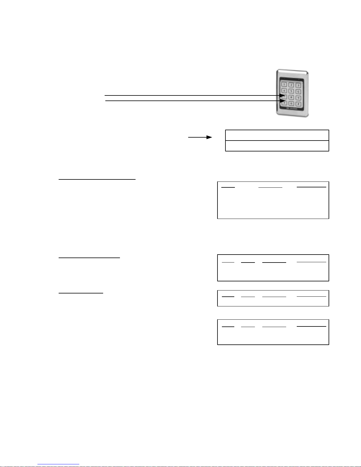
PRINTING AUDIT TRAIL TRANSACTIONS
The 935 EntryCheck
any user assigned to a User Group given the authorization to program users) can retrieve audit
transactions from a printer connected directly to the 935 control module.
1. Enter 7
*
™
logs the last 750 audit trail transactions. Authorized users (master code holder or
2. Enter the Master Code (or a User Code who is authorized to program), followed by #
Example: 7 123 #
This opens programming and causes
*
Red LED Green LED
Slow Flash Solid
3. Set Audit Trail Printing Options
Audit Trail Printing Options
1# To Print All Transaction Types
2# To Print Critical Transactions Only
3# To Print User ID and User Code/PIN
4# To Print User ID Only(No User Code)
Critical Transactions include:
*
Tamper, Door Ajar, Duress and Break-In
*
Keypad Status after Step Completion
Beep
Triple
Triple
Triple
Triple
Red LED
Slow Flash
Slow Flash
Slow Flash
Slow Flash
Green LED
Solid
Solid
Solid
Solid
4. User Selection (Default: All Users)
Select a Specific User
A) Enter 7 #
B) Enter User ID
(1-499, 500 for Temp), followed by #
Select All Users
A) Enter 8 #
5. Printing Audit Transactions
A) Enter 9 #
B) Enter the Number of Transactions to print (1-750), followed by #
C) To print additional Transactions, return to step A). To modify User Selection, return to step 4.
6. Enter to complete programming sequence and reset the system to normal operation.
**
Step
A)
B)
Step
A)
Step
A)
B)
Beep
Double
Triple
Beep
Triple
Beep
Double
Triple
Red LED
Slow Flash
Slow Flash
Red LED
Slow Flash
Red LED
Slow Flash
Slow Flash
Green LED
Slow Flash
Solid
Green LED
Solid
Green LED
Slow Flash
Solid
P:\INSTALLATION INST\ACCESS CONTROL\INST-935.vsd 0505 Page 24
Page 25
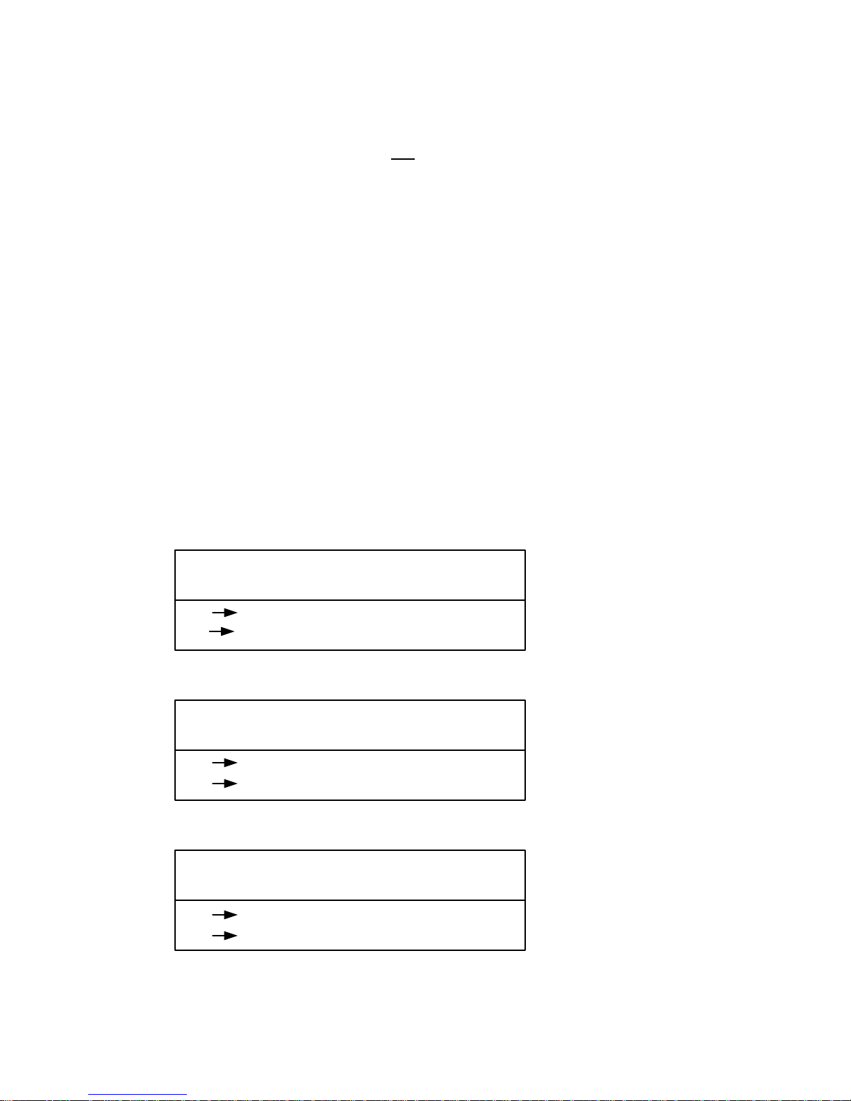
NORMAL OPERATION
On the Keypad, a solid green LED indicates that the door is unlocked. A solid red LED indicates that
the door is locked. Individual Users may gain access depending on the time zone authorization of the
User Group they have been assigned to and
EntryCheck
-When entering an Individual User Code to gain access, it must be followed by “#”.
-If access is denied for a valid User Code, be sure this User’s User Group has authorization for the
current day of the week and time of the day. Also check the Time Clock to verify the Time, Date and
Day of the Week are properly set.
™
’s time clock.
the current time/date programmed into the 935
USER COMMANDS
Depending on how the 935 EntryCheck™’s System Options are configured, User Commands are used
to operate Manual or Timed Latching and the 2
digits entered after an authorized user code. Authorization to use these Commands depends on
privileges or restrictions assigned to each User Group.
A) Enter the Master Code or an Authorized User Code, followed by #
B) As the Main Relay activates, the green LED will flash for 5 seconds (with each key press). While
the green LED is flashing, enter one (or more) of the following User Commands:
nd
and 3rd Relays. The User Commands are trailing
Latching (Main Relay
0 # to Latch the Door Closed
1 # to Latch the Door Open
Relay #2 (Configured for Auxiliary Device)
2 # to Turn Relay #2 OFF
3 # to Turn Relay #2 ON
Relay #3 (Configured for Auxiliary Device)
4 # to Turn Relay #3 OFF
5 # to Turn Relay #3 ON
P:\INSTALLATION INST\ACCESS CONTROL\INST-935.vsd 0505 Page 25
Page 26

TROUBLESHOOTING
These are a few troubleshooting suggestions to help assist with any problems you may experience. If the
problem continues or is not answered here, please call Security Door Controls (SDC) technical support at
1- (800) 413-8783. You can also visit SDC on the web at sdcsecurity.com.
I Changed the code, but the old code still unlocks the door
Remember there are a total of 500 Codes (1 Master Code and 499 User Codes) for the 935
EntryCheck™. Make sure you changed the desired code. It is recommended you Delete the User by
User Code then program the new user code.
The Keypad beeps but the door does not unlock
If the Keypad beeps but an authorized code does not unlock the door, there is an easy test to check
the wiring hookup to the primary
circuit board, locate and momentarily short the “GND” and “REMOTE” screws. This will activate the
output (same as if you enter a valid programmed code at the Keypad). If this test does not
lock, you may have wired the lock incorrectly to the 935 EntryCheck
page 28). If this test does activate the output (you should hear the relay click and the locking device
should unlock), then the problem may be one of the following:
locking device (the device connected to the Main Relay). On the
™
(see Typical Wiring Diagrams –
activate the
Programming
-If the unit has just been installed, the problem is most likely with programming the user
codes. Review Programming of Individual Users. Verify that the time clock is set to the correct time.
Also verify the User’s User Group Time Zone authorization.
Code Loss
- (Existing installations) There are typically two reasons for code loss, static or inductive
kickback. There is no way to determine if the system has been affected by either of these, however,
you can reprogram the system codes as described in User Code Programming. It is very important
the system is properly grounded and the MOV has been installed, otherwise static and code loss may
be an ongoing problem.
Keypad is completely dead
Interrupted Power - First check your power supply to see that power has not been cut off. Using a
voltmeter, check the incoming voltage on terminal strip “B” (12-24V AC/DC IN or the POWER TAP
DC+). If the voltage reads low, the electric locking device may be drawing too much current. To test,
remove the wires to the device and recheck the voltage. If the voltage now reads normal, check the
current draw of the locking device and make sure it falls within the system specifications.
Blown Fuse - Check the fuse on the circuit board. The purpose is to protect the power supply and
circuitry. If your locking device is drawing too much current or there is a short, the fuse will blow.
Replace with a 2 Amp Slo Blo only. A spare fuse is provided in the spare parts kit. Although the fuse
may appear intact, it is best to check with a voltmeter.
Keypad beeps all by itself
Random Beeping - Check for bad circuit ground going to the keypad. Is the black wire from the wiring
cable securely fastened to the screw on Terminal strip “A”? Check for bent pins on the back of the
keypad. Also check EARTH ground.
P:\INSTALLATION INST\ACCESS CONTROL\INST-935.vsd 0505 Page 26
Page 27
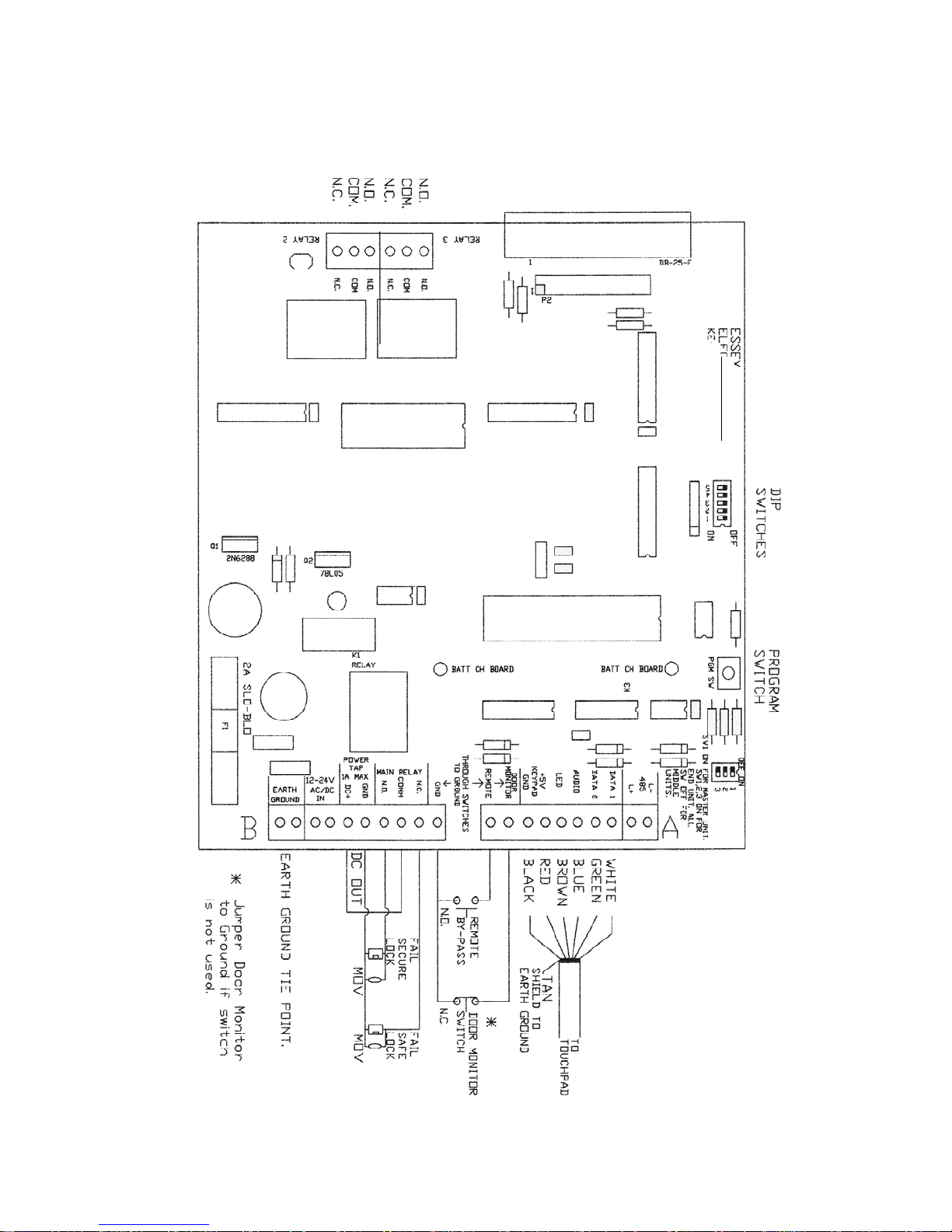
APPENDIX A – CIRCUIT BOARD LAYOUT
P:\INSTALLATION INST\ACCESS CONTROL\INST-935.vsd 0505 Page 27
Page 28
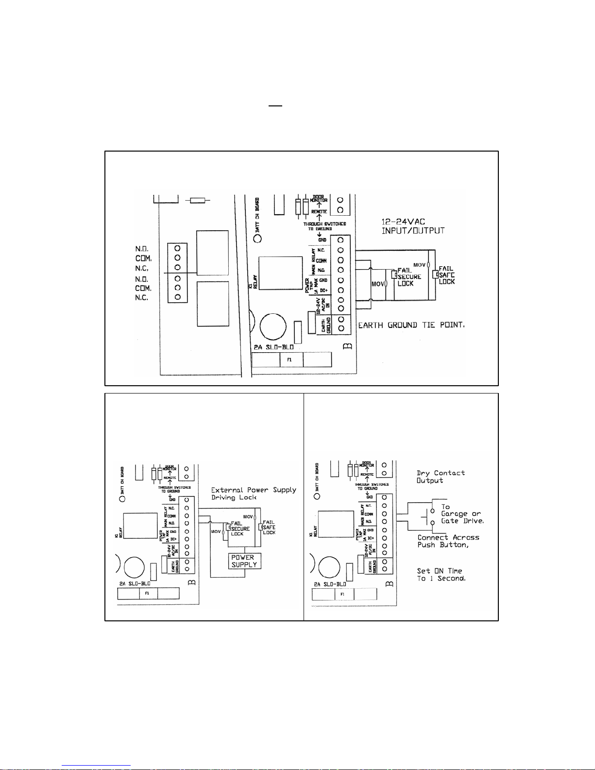
APPENDIX B – TYPICAL WIRING DIAGRAMS
Note: Some low current strikes or relays will cause relay chatter due to inductive kickback. Attach MOV
across strike or relay to eliminate chatter. Do not use MOV if switching voltages higher than 36V or dry
contact output.
Fail Safe or Fail Secure Lock controlled by 935 EntryCheck
12-24VAC Input/Output
Fail Safe or Fail Secure Lock
Controlled by 935 EntryCheck
And Powered by External
Power Supply
™
Garage Door or Gate Drive
Controlled by 935 EntryCheck
Dry Contact Output
™
™
P:\INSTALLATION INST\ACCESS CONTROL\INST-935.vsd 0505 Page 28
Page 29
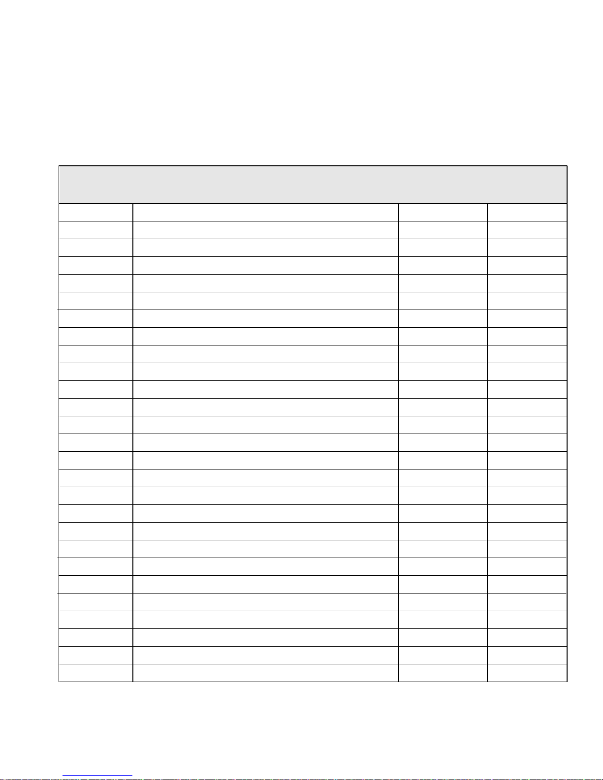
APPENDIX C – USER PROGRAMMING FORM
To Add a User: 1, Authorizied Code #, User ID #, User Code #, User Group #, , .
To Delete a User by ID: 1, Authorized Code #, 3 #, User ID to delete #, , .
To Delete a User by User Code: 1, Authorized Code #, 4 #, User Code to delete #, , .
For additional programming information, please refer to the Installation and Operations Manual.
User ID
(1-499)
*
*
User Name
**
**
****
*
User Code/PIN
(3 to 8 Digets)
****
User Group
(01-16)
P:\INSTALLATION INST\ACCESS CONTROL\INST-935.vsd 0505 Page 29
Page 30
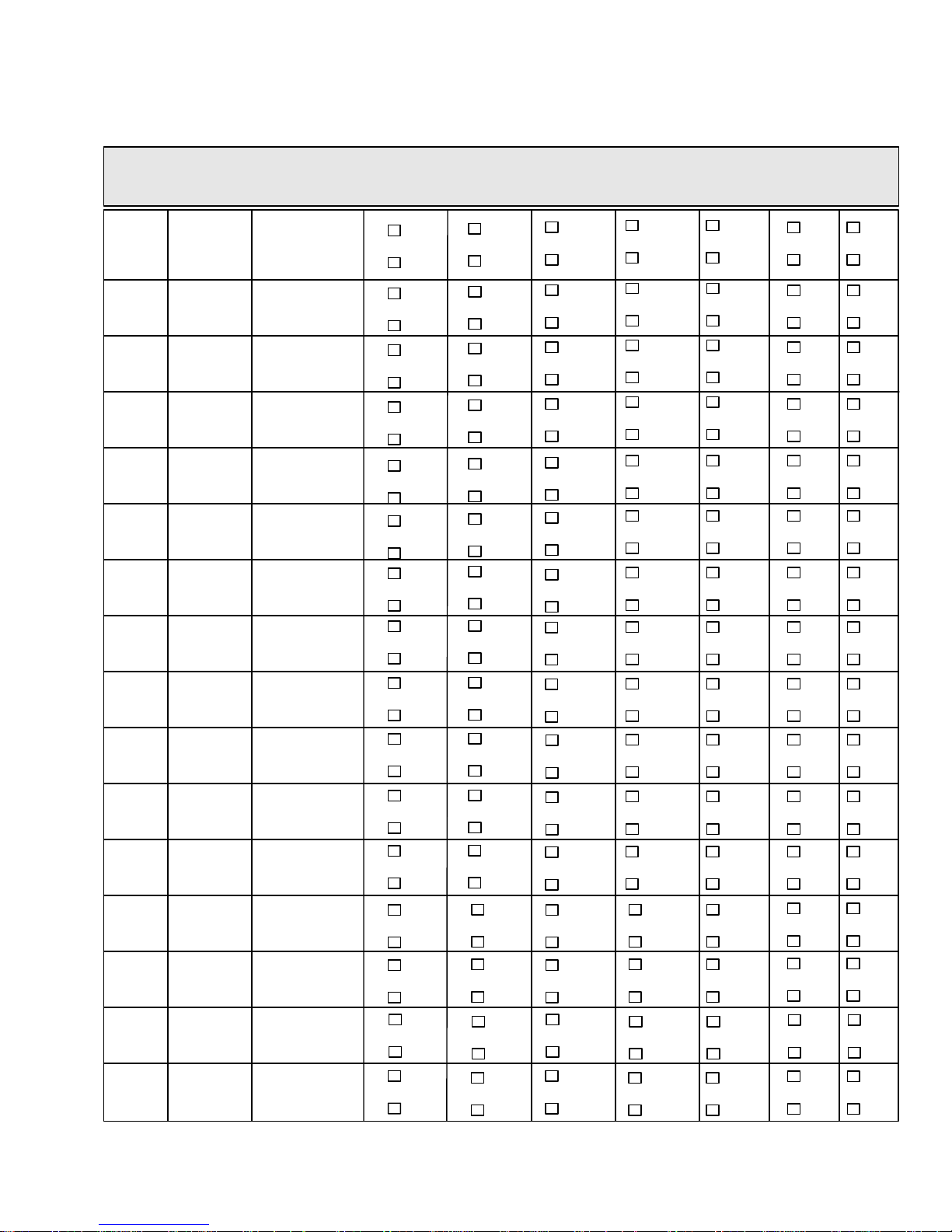
APPENDIX D – USER GROUP CONFIGURATION
User
Group
01
02
03
04
05
06
07
08
09
10
11
12
13
14
15
16
Days of
Entry
Times of
Entry
Latch
Yes
No
Yes
No
Yes
No
Yes
No
Yes
No
Yes
No
Yes
No
Yes
No
Yes
No
Yes
No
Yes
No
Yes
No
Yes
No
Yes
No
Yes
No
Yes
No
Temp
User
Yes
No
Yes
No
Yes
No
Yes
No
Yes
No
Yes
No
Yes
No
Yes
No
Yes
No
Yes
No
Yes
No
Yes
No
Yes
No
Yes
No
Yes
No
Yes
No
Delete
User
Yes
No
Yes
No
Yes
No
Yes
No
Yes
No
Yes
No
Yes
No
Yes
No
Yes
No
Yes
No
Yes
No
Yes
No
Yes
No
Yes
No
Yes
No
Yes
No
PGM
User
Yes
No
Yes
No
Yes
No
Yes
No
Yes
No
Yes
No
Yes
No
Yes
No
Yes
No
Yes
No
Yes
No
Yes
No
Yes
No
Yes
No
Yes
No
Yes
No
Relay
# 2
Yes
No
Yes
No
Yes
No
Yes
No
Yes
No
Yes
No
Yes
No
Yes
No
Yes
No
Yes
No
Yes
No
Yes
No
Yes
No
Yes
No
Yes
No
Yes
No
Relay
# 3
Yes
No
Yes
No
Yes
No
Yes
No
Yes
No
Yes
No
Yes
No
Yes
No
Yes
No
Yes
No
Yes
No
Yes
No
Yes
No
Yes
No
Yes
No
Yes
No
Holiday
Access
Yes
No
Yes
No
Yes
No
Yes
No
Yes
No
Yes
No
Yes
No
Yes
No
Yes
No
Yes
No
Yes
No
Yes
No
Yes
No
Yes
No
Yes
No
Yes
No
P:\INSTALLATION INST\ACCESS CONTROL\INST-935.vsd 0505 Page 30
 Loading...