

Page 1
EZ Option Upgrade Kits - Emlock© 1511, 1513, 1571, 1573
EMLock EZ Kits
Field Upgradeable Option Modules for 1511, 1513, 1571, 1573
SDC’s patented EMLock design represents the pinnacle of magnetic lock evolution.
The modular EMLock assembly makes them easy to stock, install, upgrade and maintain.
Field Upgradeable by Distributors, Installers and Maintenance Staff
No need to ever remove a lock from the frame to upgrade or exchange
internal components.
FIELD UPGRADE
• Relock Delay Timer
• Magnetic Bond Sensor
• Door Status Sensors
• Anti-Tamper Switch
• Holding Force Upgrade
• Energy Saver Upgrade
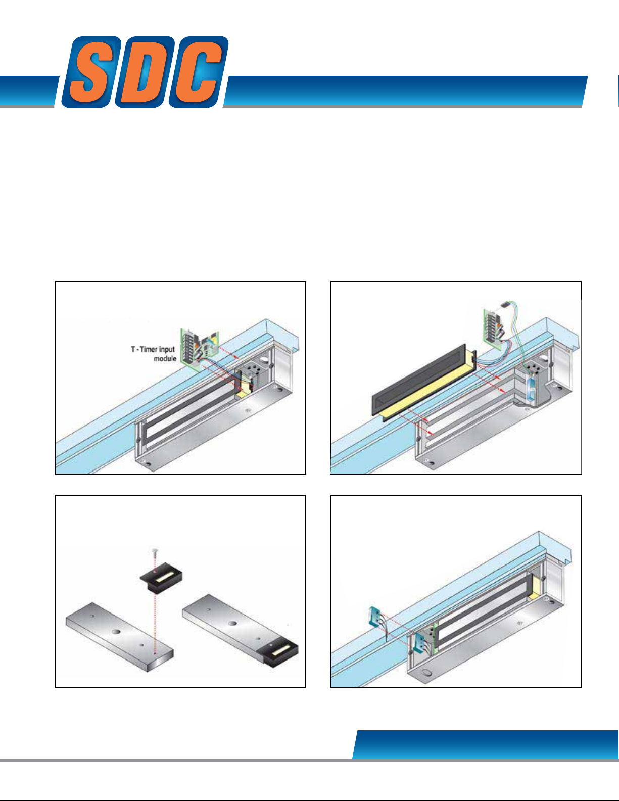
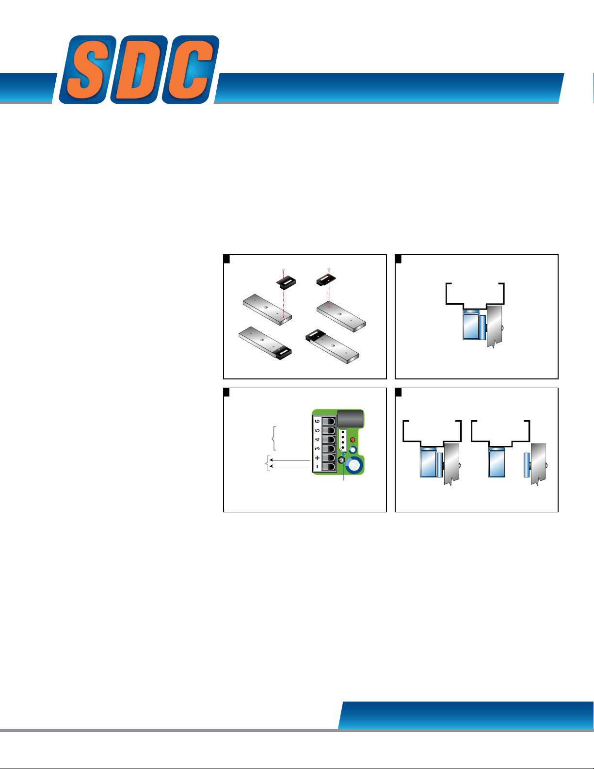
EZ-T-10 TIMER INPUT MODULE
Modular Kit
EZ-D-10: DOOR POSITION SENSOR
Modular Kit
EZ-B-10 MAGNETIC
BOND SENSOR
Modular Kit
EZ-A: ANTI-TAMPER SWITCH
Modular Kit
SECURITY DOOR CONTROLS
sdcsecurity.com [email protected]
Page 2
sdcsecurity.com [email protected]
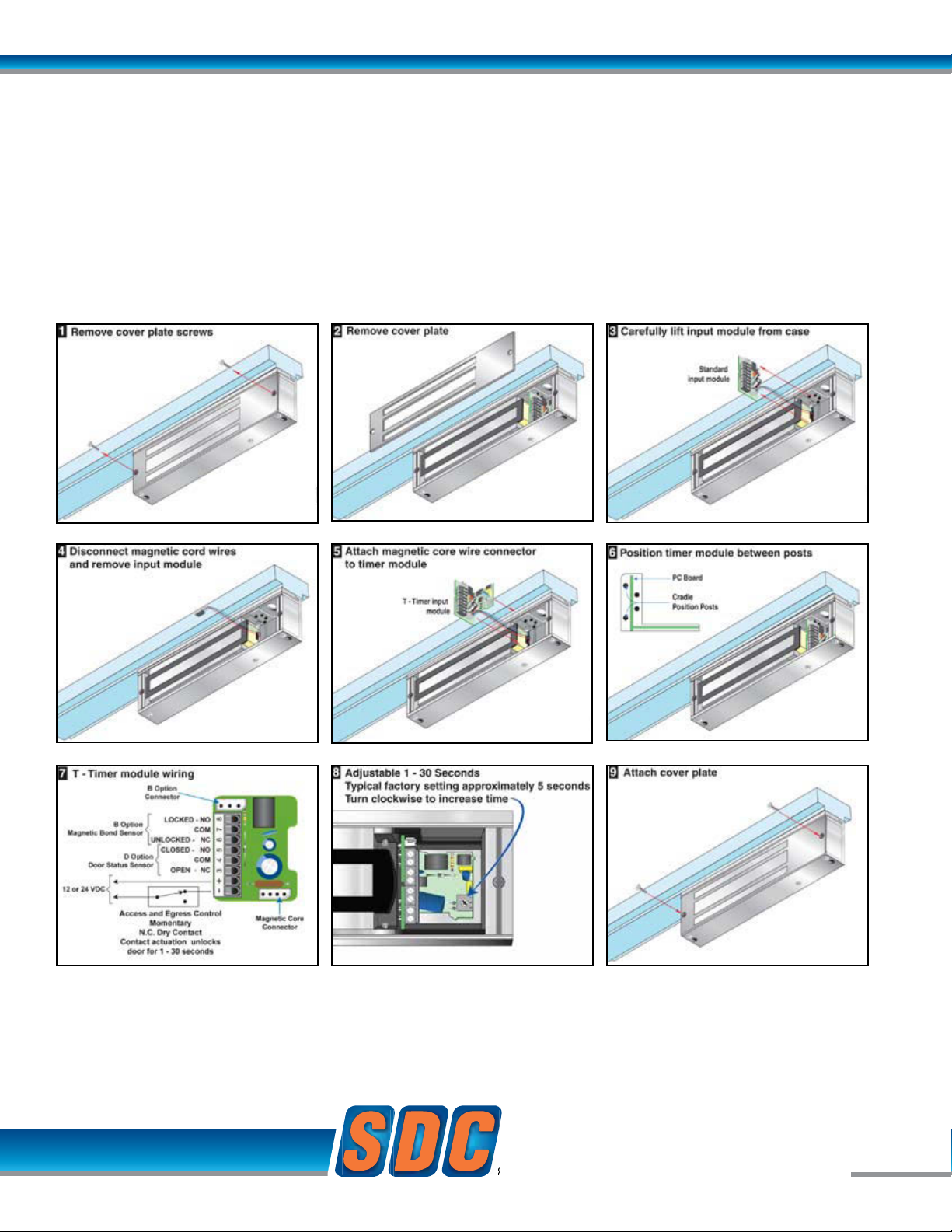
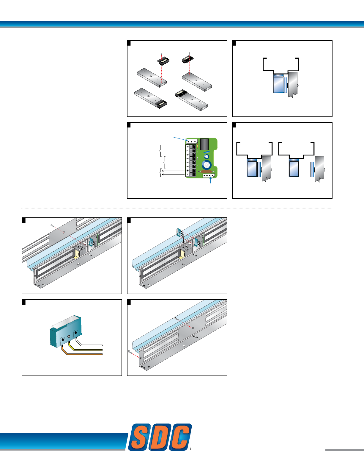
EZ-T-10 TIMER INPUT MODULE
Modular Kit
Relock Delay Timer, Adjustable 1 to 30 Seconds.
Application: The Timer Input Module delays relocking of access controlled doors to provide persons ample time needed
for entry or egress. Momentary interruption of power to the lock input activates the timer module.
Momentary, N.C. Dry Contact required. Contact actuation unlocks the door for 1 – 30 seconds.
SECURITY DOOR CONTROLS
SECURITY DOOR CONTROLS
© 2007 Security Door Controls Printed in the U.S.A. LIT-Datasheet date qty vendor
www.sdcsecurity.com [email protected]
[t] 800.413.8783 805.494.0622 [f] 805.494.8861
801 Avenida Acaso, Camarillo CA 93012 • PO Box 3670, Camarillo CA 93011-3670
Page 3
EZ Option Upgrade Kits - Emlock© 1511, 1513, 1571, 1573
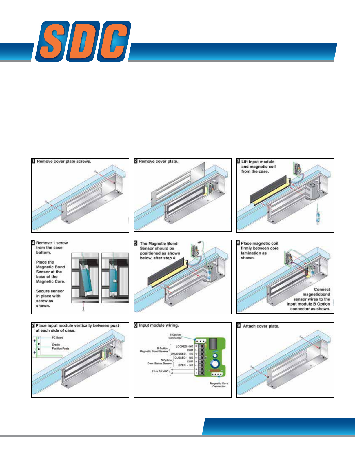
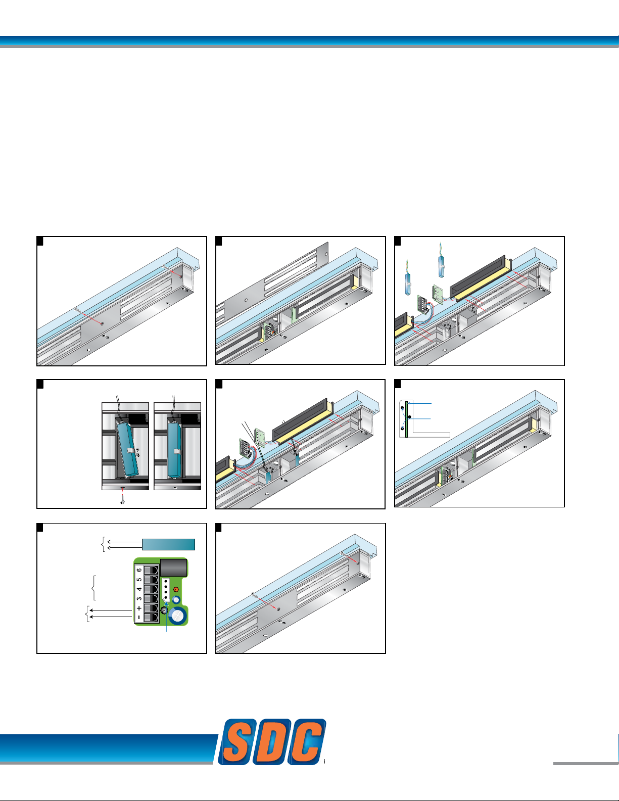
EZ-B-10 MAGNETIC BOND SENSOR
Modular Kit
* Not available for 1513, 1573
While a Door Status Sensor indicates the door is open
or closed, SDC’s Magnetic Bond Sensor provides higher
security monitoring by indicating the locked / unlocked
mode, tampering and low holding force. The use of
both the door status and magnetic bond sensor is
recommended for high security applications.
Application: Lock secure status annunciation,
mantrap system logic,
CCTV camera activation.
Output: SPDT Dry Contact,
250 mA @ 12/24VDC
SECURITY DOOR CONTROLS
sdcsecurity.com [email protected]
Page 4
sdcsecurity.com [email protected]
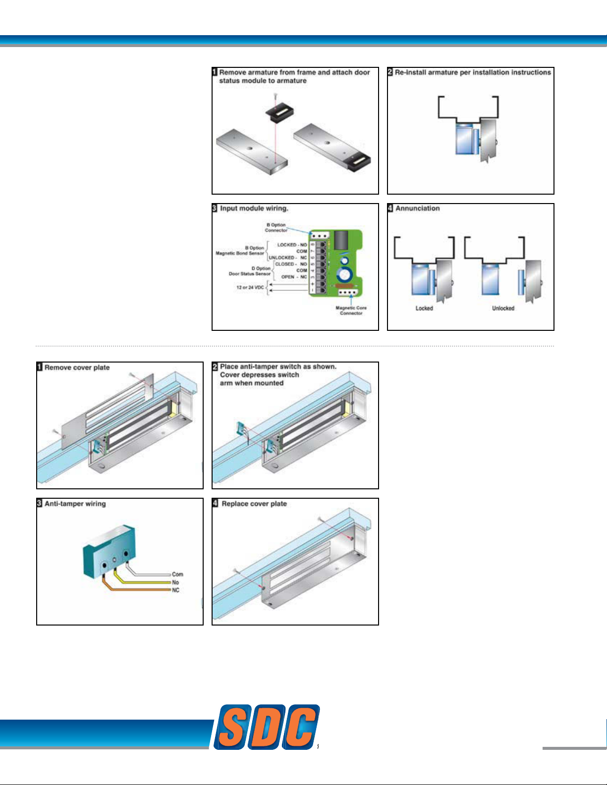
EZ-D-10: DOOR
POSITION SENSOR
Modular Kit
Indicates the door is open
and closed.
* Not available for 1513, 1573
Application:
Door position status annunciation,
anti-tailgating, interlock, mantrap and
communicating bathroom system
logic.
Output:
SPDT Dry Contact, 250 mA
@ 12/24VDC
EZ-A: ANTI-TAMPER
SWITCH - Modular Kit
Indicates cover plate removal
Output:
SPDT Dry Contact, 3 Amp @ 12/24VDC
SECURITY DOOR CONTROLS
SECURITY DOOR CONTROLS
© 2007 Security Door Controls Printed in the U.S.A. LIT-Datasheet date qty vendor
www.sdcsecurity.com [email protected]
[t] 800.413.8783 805.494.0622 [f] 805.494.8861
801 Avenida Acaso, Camarillo CA 93012 • PO Box 3670, Camarillo CA 93011-3670
Page 5
EZ Option Upgrade Kits - Emlock© 1511, 1513, 1571, 1573
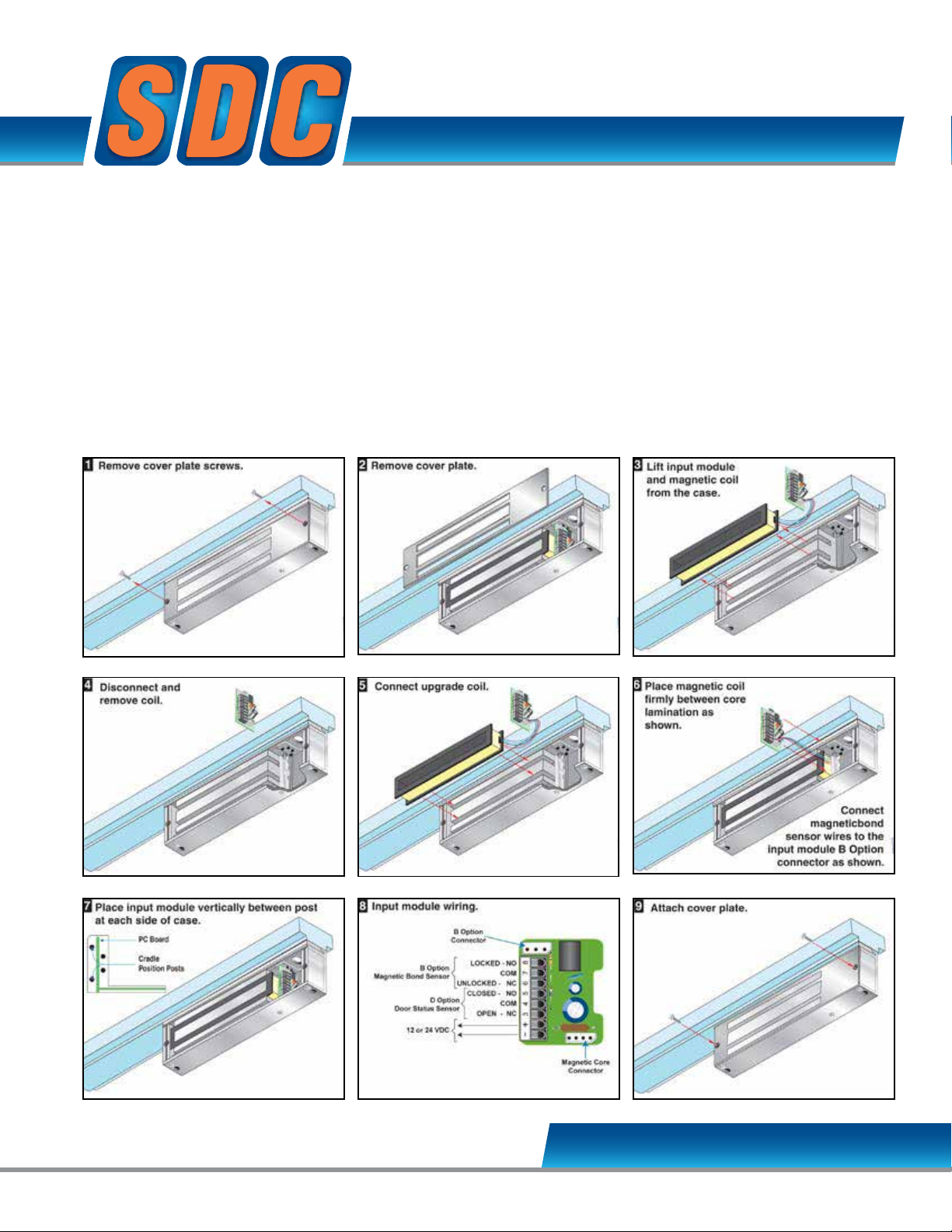
EZ – 1510W Holding Force Upgrade
EZ – 1570W Energy Saver Upgrade
All 1511, 1512, 1513, 1571, 1572 and 1573 magnetic coils are field interchangeable without removing the lock from the frame. There is no reason
to remove and ship a lock for exchange.
Benefits of this interchangeability include:
• EZ-1510W Holding Force Upgrade: Exchange 1200 lb coil with
1650 lb holding force coil
• EZ-1570W Energy Saver Upgrade: Save on power supply and
long term energy costs by exchanging 8.4 Watt,1650 lb coil
with 3 Watt, 1200 lb holding force coil
• Eliminate labor, shipping costs and time associated with special
orders or complete lock removal and replacement.
Applications
Distributors with limited stock may exchange coils to fulfill specific
special sales needs, i.e. a 1570 with Dark Bronze finish may be
upgraded to a 1511 with dark bronze finish and visa versa.
Installers may field upgrade to an Energy Saver where power supply
capacity is limited or upgrade to higher holding force where 1200 lbs
holding force proves inadequate, i.e. psychiatric or rehab center
applications.
SECURITY DOOR CONTROLS
sdcsecurity.com [email protected]
Page 6

sdcsecurity.com [email protected]
SECURITY DOOR CONTROLS
SECURITY DOOR CONTROLS
© 2007 Security Door Controls Printed in the U.S.A. LIT-Datasheet date qty vendor
www.sdcsecurity.com [email protected]
[t] 800.413.8783 805.494.0622 [f] 805.494.8861
801 Avenida Acaso, Camarillo CA 93012 • PO Box 3670, Camarillo CA 93011-3670
Page 7
EZ Option Upgrade Kits - Emlock© 1512 / 1572
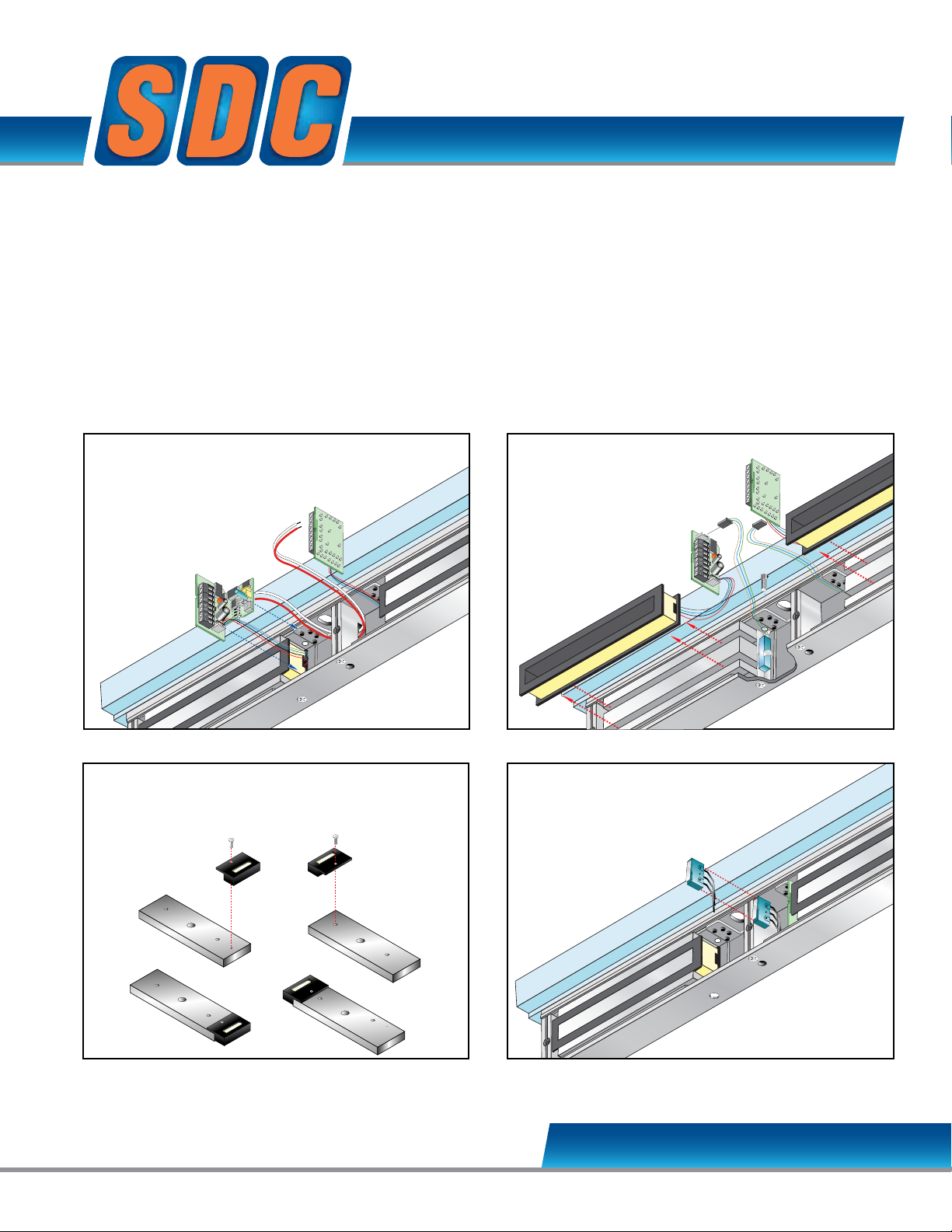
Re-install armature per installation instructionsAttach door status module to each armature
Attach magnetic core
wire connector to
timer module
Connect
output wires
5 6
Position timer modules
between posts
T - Timer input
module
Re-install armature per installation instructionsAttach door status module to each armature
5
The Magnetic Bond
+
3
4
5
6
7
8
EMLock EZ Upgrade Kits
Field Upgradeable Option Modules for 1512 and 1572
SDC’s patented EMLock design represents the pinnacle of magnetic lock evolution.
The modular EMLock assembly makes them easy to stock, install, upgrade and maintain.
Field Upgradeable by Distributors, Installers and Maintenance Staff
No need to ever remove a lock from the frame to upgrade or exchange
internal components.
FIELD UPGRADE
• Relock Delay Timer
• Magnetic Bond Sensor
• Door Status Sensors
• Anti-Tamper Switch
• Holding Force Upgrade
• Energy Saver Upgrade
EZ-T-10 TIMER INPUT MODULE
Modular Kit
EZ-D-10: DOOR POSITION SENSOR
Modular Kit
EZ-A: ANTI-TAMPER SWITCH
Modular Kit
SECURITY DOOR CONTROLS
sdcsecurity.com [email protected]
Page 8
sdcsecurity.com [email protected]
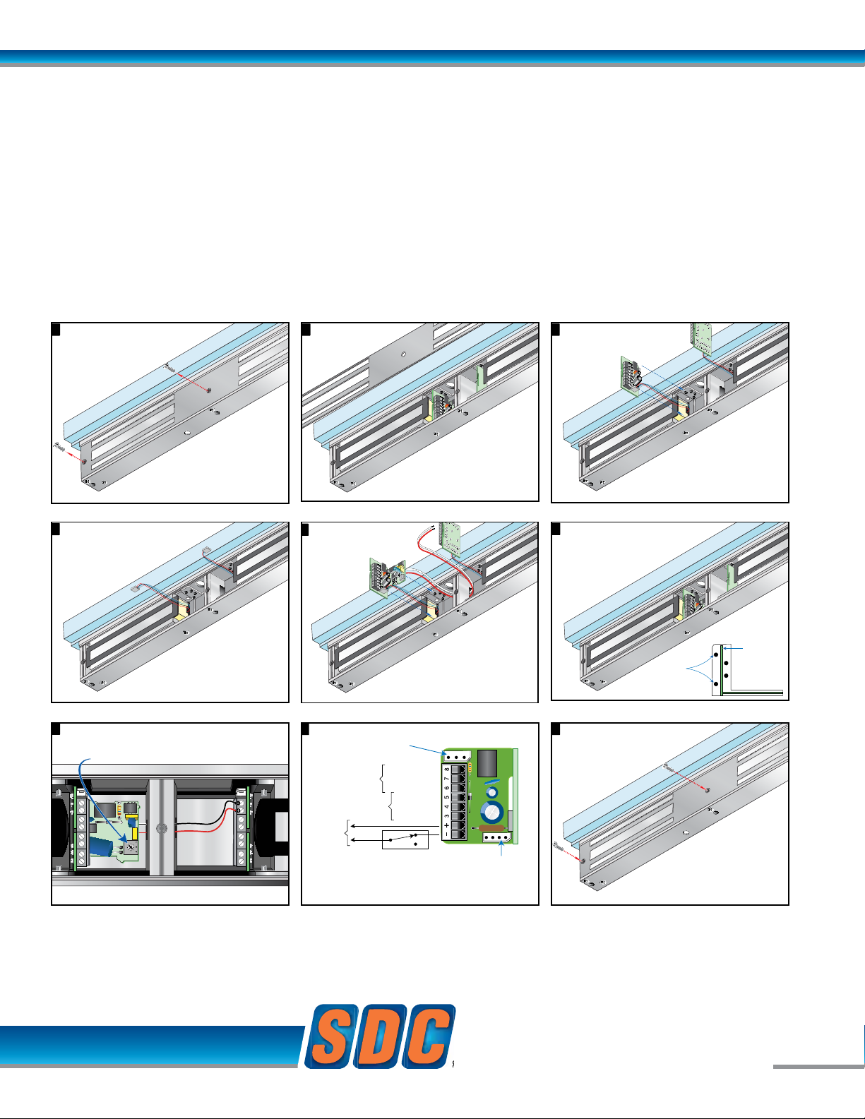
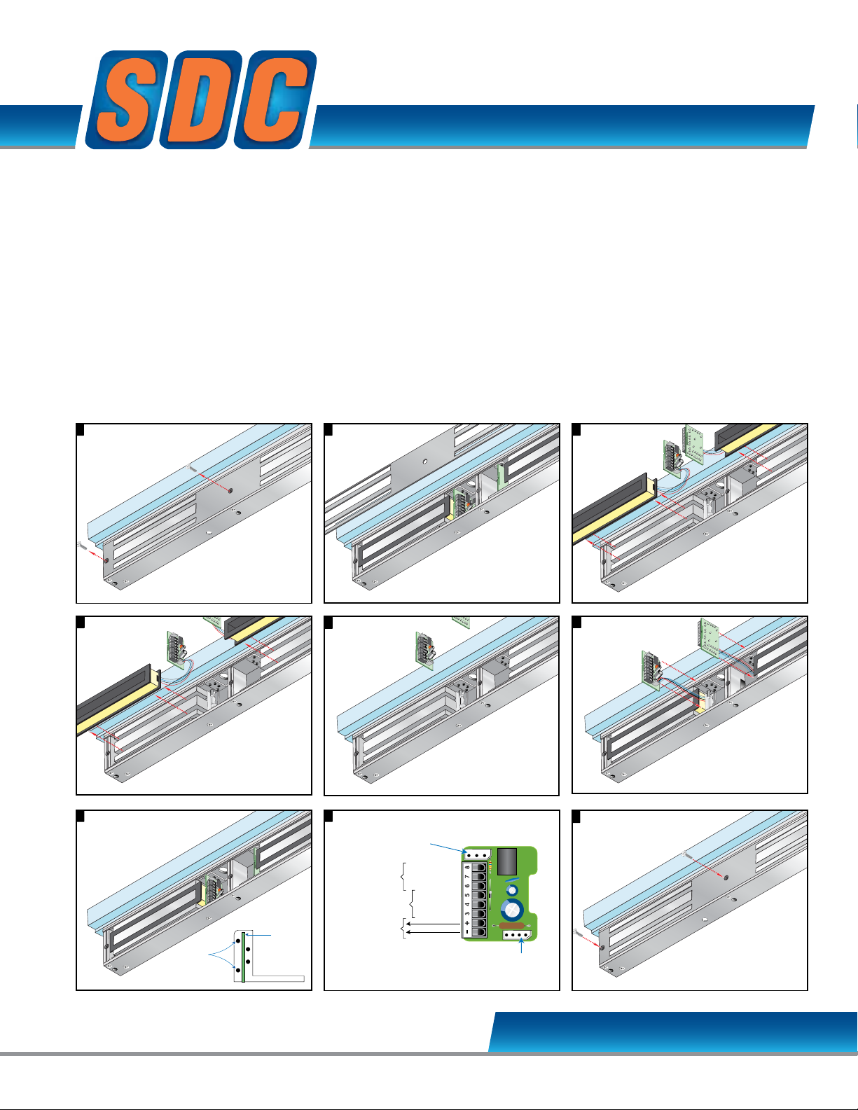
Remove cover plate screws
1
Remove cover plate
2
Remove cover plate
2
Carefully lift input
modules from case
3
Standard
input module
Carefully lift input
modules from case
3
Standard
input module
Disconnect magnetic
cord wires and remove
input module
4
Remove cover plate screws
1
Attach magnetic core
wire connector to
timer module
Connect
output wires
of timermodule
to input terminals
1 and 2 of standards
input module.
5
Remove cover plate
2
6
Position timer modules
between posts
Adjustable 1 - 30 Seconds
Typical factory setting approximately 5 seconds
Turn clockwise to increase time
Cradle
Position Posts
PC Board
T - Timer input
module
Remove cover plate
2
6
Position timer modules
between posts
Adjustable 1 - 30 Seconds
Typical factory setting approximately 5 seconds
Turn clockwise to increase time
Cradle
Position Posts
PC Board
Carefully lift input
modules from case
3
7
Disconnect magnetic
cord wires and remove
input module
4
T - Timer module wiring8
Adjustable 1 - 30 Seconds
Typical factory setting approximately 5 seconds
Turn clockwise to increase time
D2
B Option
Connector
B Option
Magnetic Bond Sensor
D Option
Door Status Sensor
Magnetic Core
Connector
12 or 24 VDC
LOCKED - NO
COM
UNLOCKED - NC
CLOSED - NO
COM
OPEN - NC
Access and Egress Control
Momentary
N.C. Dry Contact
Contact actuation unlocks
door for 1 - 30 seconds
Standard
input module
Disconnect magnetic
cord wires and remove
input module
4
T - Timer module wiring8
B Option
Connector
B Option
Magnetic Bond Sensor
D Option
Door Status Sensor
Magnetic Core
Connector
12 or 24 VDC
LOCKED - NO
COM
UNLOCKED - NC
CLOSED - NO
COM
OPEN - NC
Access and Egress Control
Momentary
N.C. Dry Contact
Contact actuation unlocks
door for 1 - 30 seconds
Remove cover plate screws
1
Attach magnetic core
wire connector to
timer module
Connect
output wires
of timermodule
to input terminals
1 and 2 of standards
input module.
5
9 Attach cover plate
T - Timer input
module
1 only required
EZ-T-10 TIMER INPUT MODULE
Modular Kit
Relock Delay Timer, Adjustable 1 to 30 Seconds. 1 only required for double EMLock®.
Application: The Timer Input Module delays relocking of access controlled doors to provide persons ample time needed
for entry or egress. Momentary interruption of power to the lock input activates the timer module.
Momentary, N.C. Dry Contact required. Contact actuation unlocks the door for 1 – 30 seconds.
Only 1 timer module is required for double Emlocks®.
SECURITY DOOR CONTROLS
© 2010 Security Door Controls Printed in the U.S.A. LIT-EZ Option Kit Upgrades 12.10
SECURITY DOOR CONTROLS
www.sdcsecurity.com [email protected]
[t] 800.413.8783 805.494.0622 [f] 805.494.8861
801 Avenida Acaso, Camarillo CA 93012 • PO Box 3670, Camarillo CA 93011-3670
Page 9
EZ Option Upgrade Kits - Emlock© 1512 / 1572
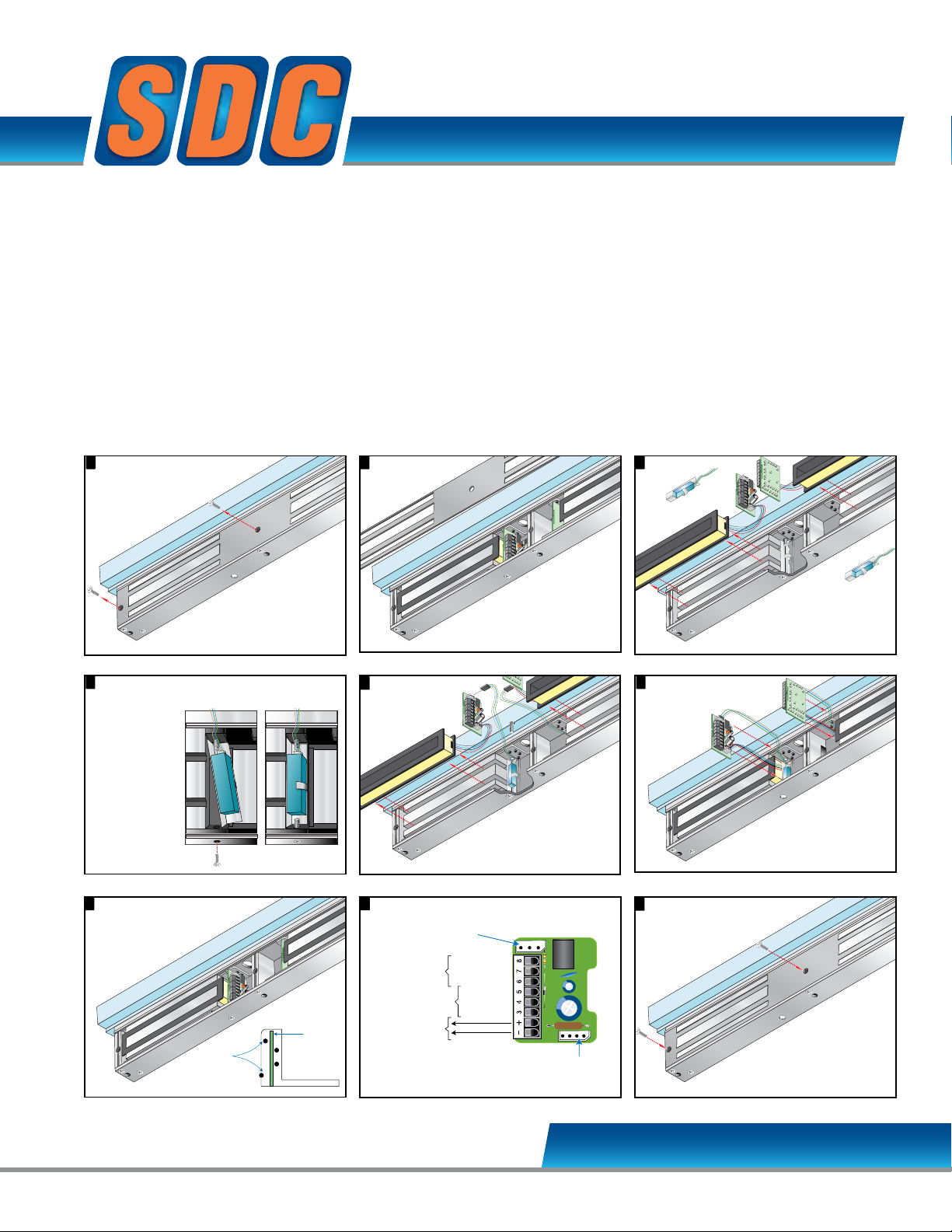
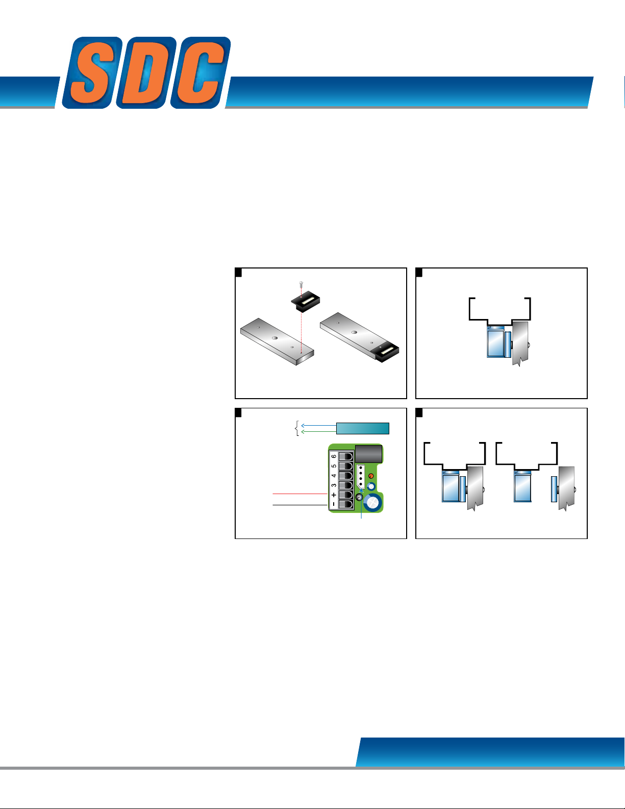
Remove cover plate screws.
1 2
Remove
cover plate.
2
Remove
3
Lift input module
and magnetic coil
from the case.
3
+
3
4
5
6
7
8
3
3
+
3
4
5
6
7
8
4
Remove 2 screw
Remove cover plate screws.
1 2
Remove
cover plate.
6
Place magnetic coil firmly
between core lamination
as shown.
connector as shown.
5
+
3
4
5
6
7
8
Remove
cover plate.
6
Place magnetic coil firmly
Input module wiring.8
B Option
Connector
B Option
Magnetic Bond Sensor
D Option
Door Status Sensor
Magnetic Core
Connector
12 or 24 VDC
LOCKED - NO
COM
UNLOCKED - NC
CLOSED - NO
COM
OPEN - NC
3
7
Lift input module
and magnetic coil
from the case.
43
Place input module vertically
Remove 2 screw
from the case
bottom.
Place the
Magnetic Bond
Sensors at the
base of each
Magnetic Core.
Secure sensor
in place with
screw as
shown.
+
3
4
5
6
7
8
+
3
4
5
6
7
8
Input module wiring.8
4
Remove 2 screw
from the case
bottom.
Place the
Magnetic Bond
Sensors at the
base of each
Magnetic Core.
Secure sensor
in place with
screw as
shown.
Remove cover plate screws.
1
9
5
The Magnetic Bond
Sensor should be
positioned as shown
below, after step 4.
+
3
4
5
6
7
8
Specify 2 for 1512, 1572
Modular Kit
While a Door Status Sensor indicates the door is open
or closed, SDC’s Magnetic Bond Sensor provides higher
security monitoring by indicating the locked / unlocked
mode, tampering and low voltage. The use of
both the door status and magnetic bond sensor is
recommended for high security applications.
cover plate.
EZ-B-10-2 MAGNETIC BOND SENSOR
from the case
bottom.
Place the
Magnetic Bond
Sensors at the
base of each
Magnetic Core.
Secure sensor
in place with
screw as
shown.
Application: Lock secure status annunciation,
mantrap system logic,
CCTV camera activation.
Output: 2 Contacts provided
2-SPDT Dry Contact,
250 mA @ 12/24VDC
positioned as shown
The Magnetic Bond
Sensor should be
below, after step 4.
Lift input module
and magnetic coil
from the case.
between core lamination
as shown.
Connect
magnetic
bond sensor
wires to the input
module B Option
connector as shown.
between post at each
side of case.
B Option
Magnetic Bond Sensor
D Option
Door Status Sensor
Cradle
Position Posts
PC Board
12 or 24 VDC
B Option
Connector
LOCKED - NO
COM
UNLOCKED - NC
CLOSED - NO
COM
OPEN - NC
Attach cover plate.
Magnetic Core
Connector
SECURITY DOOR CONTROLS
sdcsecurity.com [email protected]
Page 10
sdcsecurity.com [email protected]
1
3 4
2
Input module wiring. Annunciation
Re-install armature per installation instructionsAttach door status module to each armature
3 4
2
Input module wiring. Annunciation
Re-install armature per installation instructionsAttach door status module to each armature
3 4
Input module wiring. Annunciation
B Option
Connector
B Option
Magnetic Bond Sensor
D Option
Door Status Sensor
Magnetic Core
Connector
12 or 24 VDC
LOCKED - NO
COM
UNLOCKED - NC
CLOSED - NO
COM
OPEN - NC
Locked Unlocked
Locked Unlocked
1
3 4
2
Input module wiring. Annunciation
Re-install armature per installation instructionsAttach door status module to each armature
Remove cover plate Replace cover plate
Anti-tamper wiring
1 2
3 4
2
Input module wiring. Annunciation
Re-install armature per installation instructionsAttach door status module to each armature
Anti-tamper wiring
B Option
Connector
B Option
Magnetic Bond Sensor
D Option
Door Status Sensor
Magnetic Core
Connector
12 or 24 VDC
LOCKED - NO
COM
UNLOCKED - NC
CLOSED - NO
COM
OPEN - NC
3
2
3 4
Input module wiring. Annunciation
Anti-tamper wiring
Com
No
NC
B Option
Connector
B Option
Magnetic Bond Sensor
D Option
Door Status Sensor
Magnetic Core
Connector
12 or 24 VDC
LOCKED - NO
COM
UNLOCKED - NC
CLOSED - NO
COM
OPEN - NC
Locked Unlocked
3 4
Locked Unlocked
4
EZ-D-10-2: DOOR
POSITION SENSOR
Modular Kit
Indicates the door is open
and closed.
Application:
Door position status annunciation,
anti-tailgating, interlock, mantrap
and communicating bathroom
system logic.
Output: 2 Modules provided
SPDT Dry Contact, 250 mA
@ 12/24VDC
1 only required
EZ-A: ANTI-TAMPER
SWITCH - Modular Kit
Indicates cover plate removal
Output:
SPDT Dry Contact, 3 Amp @ 12/24VDC
SECURITY DOOR CONTROLS
© 2010 Security Door Controls Printed in the U.S.A. LIT-EZ Option Kit Upgrades 12.10
SECURITY DOOR CONTROLS
www.sdcsecurity.com [email protected]
[t] 800.413.8783 805.494.0622 [f] 805.494.8861
801 Avenida Acaso, Camarillo CA 93012 • PO Box 3670, Camarillo CA 93011-3670
Page 11
EZ Option Upgrade Kits - Emlock© 1512 / 1572
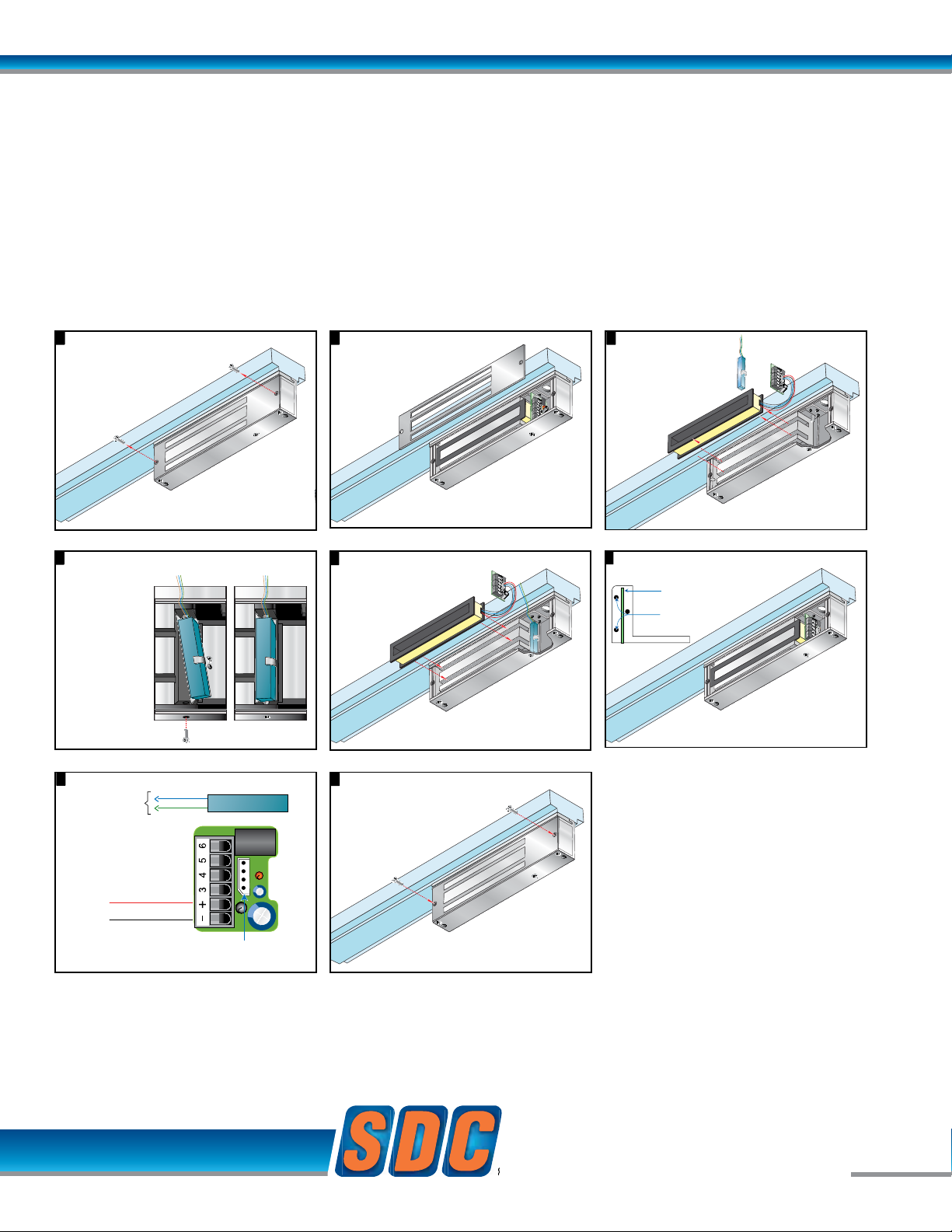
Remove cover plate screws.
1 2
Remove
cover plate.
2
Remove
3
Lift input modules
and magnetic
coils from
the case.
+
3
4
5
6
7
8
3
+
3
4
5
6
7
8
4
+
3
4
5
6
7
8
Remove cover plate screws.
1 2
Remove
cover plate.
6
Place magnetic coil
firmly between core
lamination as shown.
sensor wires to the
5
+
3
4
5
678
Remove
cover plate.
6
Place magnetic coil
Input module wiring.8
B Option
Connector
B Option
Magnetic Bond Sensor
D Option
Door Status Sensor
Magnetic Core
Connector
12 or 24 VDC
LOCKED - NO
COM
UNLOCKED - NC
CLOSED - NO
COM
OPEN - NC
3
7
Lift input modules
and magnetic
coils from
the case.
4
Place input modules
+
3
4
5
6
7
8
+
3
4
5
6
7
8
Disconnect and
remore coils
+
3
4
5
6
7
8
Input module wiring.8
4
Disconnect and
remore coils
+
3
4
5
6
7
8
Remove cover plate screws.
1
9
5
Connect
upgrade coils
+
3
4
5
6
7
8
Specify 2 for 1512, 1572
EZ – 1510W-2 Holding Force Upgrade
EZ – 1570W-2 Energy Saver Upgrade
All 1511, 1512, 1513, 1571, 1572 and 1573 magnetic coils are field interchangeable without removing the lock from the frame. There is no reason
to remove and ship a lock for exchange.
Benefits of this interchangeability include:
• EZ-1510W Holding Force Upgrade: Exchange 1200 lb coil with
1650 lb holding force coil
• EZ-1570W Energy Saver Upgrade: Save on power supply and
long term energy costs by exchanging 8.4 Watt,1650 lb coil
with 3 Watt, 1200 lb holding force coil
• Eliminate labor, shipping costs and time associated with special
orders or complete lock removal and replacement.
cover plate.
Disconnect and
remore coils
Connect
upgrade coils
Applications
Distributors with limited stock may exchange coils to fulfill specific
special sales needs, i.e. a 1570 with Dark Bronze finish may be
upgraded to a 1511 with dark bronze finish and visa versa.
Installers may field upgrade to an Energy Saver where power supply
capacity is limited or upgrade to higher holding force where 1200 lbs
holding force proves inadequate, i.e. psychiatric or rehab center
applications.
Lift input modules
and magnetic
coils from
the case.
firmly between core
lamination as shown.
vertically between posts
at each side of case.
B Option
Magnetic Bond Sensor
D Option
Door Status Sensor
Cradle
Position Posts
PC Board
12 or 24 VDC
B Option
Connector
LOCKED - NO
COM
UNLOCKED - NC
CLOSED - NO
COM
OPEN - NC
Magnetic Core
Connector
Attach cover plate.
SECURITY DOOR CONTROLS
sdcsecurity.com [email protected]
Connect
magnetic bond
sensor wires to the
input module B
Option connector
as shown.
Page 12

sdcsecurity.com [email protected]
SECURITY DOOR CONTROLS
SECURITY DOOR CONTROLS
© 2010 Security Door Controls Printed in the U.S.A. LIT-EZ Option Kit Upgrades 12.10
www.sdcsecurity.com [email protected]
[t] 800.413.8783 805.494.0622 [f] 805.494.8861
801 Avenida Acaso, Camarillo CA 93012 • PO Box 3670, Camarillo CA 93011-3670
Page 13
1
3
2
Input module wiring.
Install lock per installation instructions
Magnetic Bond Sensor
3
2
Input module wiring.
Magnetic Bond Sensor
3 4
Input module wiring. Annunciation
Locked Unlocked
EZ Option Upgrade Kits - Emlock© 1581
EMLock EZ Kits
Field Upgradeable Option Modules
SDC’s patented EMLock design represents the pinnacle of magnetic lock evolution.
The modular EMLock assembly makes them easy to stock, install, upgrade and maintain.
Field Upgradeable by Distributors, Installers and Maintenance Staff
No need to ever remove a lock from the frame to upgrade or exchange
internal components.
FIELD UPGRADE
• Magnetic Bond Sensor
• Door Status Sensors
• Tamper
EZ-D-80: DOOR
POSITION SENSOR
Modular Kit
Indicates the door is open
and closed.
Application:
Door position status annunciation,
anti-tailgating, interlock, mantrap and
communicating bathroom system
logic.
Output:
SPDT Dry Contact, 250 mA @ 12/24VDC
Attach door status module to armature
B Option
Magnetic Bond Sensor
POWER
NO
COM
NOT USED
DPS CO
{
NO
NC
Magnetic Core
Connector
Install lock per installation instructions
Locked Unlocked
SECURITY DOOR CONTROLS
sdcsecurity.com [email protected]
Page 14
sdcsecurity.com [email protected]
+
3
4
5
6
7
8
+
3
4
5
6
Remove cover plate screws.
1 2
Remove cover plate.
3
Lift input module
and magnetic coil
from the case.
4
Remove 1 screw
from the case
bottom.
Place the
Magnetic Bond
Sensor at the
base of the
Magnetic Core.
Secure sensor
in place with
screw as
shown.
+
3
4
5
6
7
8
+
3
4
5
6
Remove cover plate.
3
Lift input module
and magnetic coil
from the case.
4
Remove 1 screw
from the case
bottom.
Place the
Magnetic Bond
Sensor at the
base of the
Magnetic Core.
Secure sensor
in place with
screw as
shown.
+
3
4
5
6
3
Lift input module
and magnetic coil
from the case.
4
Remove 1 screw
from the case
bottom.
Place the
Magnetic Bond
Sensor at the
base of the
Magnetic Core.
Secure sensor
in place with
screw as
shown.
4
Remove 1 screw
from the case
bottom.
Place the
Magnetic Bond
Sensor at the
base of the
Magnetic Core.
Secure sensor
in place with
screw as
shown.
+
3
4
5
6
7
8
B Option
Magnetic Bond Sensor
NOT USED
POWER
DPS CO
NC
NO
Magnetic Core
Connector
+
3
4
5
6
Cradle
Position Posts
PC Board
+
3
4
5
6
Input module wiring.8
Remove cover plate screws.
1 2
Remove cover plate.
3
7
Lift input module
and magnetic coil
from the case.
Place input module vertically between post
a
t each side of case.
Remove 1 screw
from the case
bottom.
Place the
Magnetic Bond
Sensor at the
base of the
Magnetic Core.
Secure sensor
in place with
screw as
shown.
5
The Magnetic Bond Sensor
should be positioned as
shown below, after step 4.
+
3
4
567
8
B Option
Magnetic Bond Sensor
NOT USED
POWER
DPS CO
NC
NO
Magnetic Core
Connector
+34
5
6
Cradle
Position Posts
PC Board
Input module wiring.8
Remove cover plate.
3
7
Lift input module
and magnetic coil
from the case.
Place input module vertically between post
a
t each side of case.
Remove 1 screw
from the case
bottom.
Place the
Magnetic Bond
Sensor at the
base of the
Magnetic Core.
Secure sensor
in place with
screw as
shown.
B Option
Magnetic Bond Sensor
NOT USED
POWER
DPS CO
NC
NO
Magnetic Core
Connector
+
3
4
5
6
{
NO
COM
Input module wiring.8
3
Lift input module
and magnetic coil
from the case.
4
Remove 1 screw
from the case
bottom.
Place the
Magnetic Bond
Sensor at the
base of the
Magnetic Core.
Secure sensor
in place with
screw as
shown.
9
Attach cover plate.
4
Remove 1 screw
from the case
bottom.
Place the
Magnetic Bond
Sensor at the
base of the
Magnetic Core.
Secure sensor
in place with
screw as
shown.
9
Attach cover plate.
EZ-B-80 MAGNETIC BOND SENSOR
Modular Kit
While a Door Status Sensor indicates the door is open
or closed, SDC’s Magnetic Bond Sensor provides higher
security monitoring by indicating the locked / unlocked
mode, tampering and low holding force. The use of
both the door status and magnetic bond sensor is
recommended for high security applications.
Application: Lock secure status annunciation,
mantrap system logic,
CCTV camera activation.
Output: SPDT Dry Contact,
250 mA @ 12/24VDC
SECURITY DOOR CONTROLS
© 2007 Security Door Controls Printed in the U.S.A. LIT-Datasheet date qty vendor
SECURITY DOOR CONTROLS
www.sdcsecurity.com [email protected]
[t] 800.413.8783 805.494.0622 [f] 805.494.8861
801 Avenida Acaso, Camarillo CA 93012 • PO Box 3670, Camarillo CA 93011-3670
Page 15
EZ Option Upgrade Kits - Emlock© 1582
1
3
2
Input module wiring.
Install lock per installation instructions
Door Status Sensor
12 or 24 VDC
3
2
Input module wiring.
Door Status Sensor
12 or 24 VDC
3 4
Input module wiring. Annunciation
Locked Unlocked
EMLock EZ Kits
Field Upgradeable Option Modules
SDC’s patented EMLock design represents the pinnacle of magnetic lock evolution.
The modular EMLock assembly makes them easy to stock, install, upgrade and maintain.
Field Upgradeable by Distributors, Installers and Maintenance Staff
No need to ever remove a lock from the frame to upgrade or exchange
internal components.
FIELD UPGRADE
• Magnetic Bond Sensor
• Door Status Sensors
Specify 2 for 1582
EZ-D-80: DOOR
POSITION SENSOR
Modular Kit
Indicates the door is open
and closed.
Application:
Door position status annunciation,
anti-tailgating, interlock, mantrap and
communicating bathroom system
logic.
Output:
SPDT Dry Contact, 250 mA @ 12/24VDC
Attach door status module to armature
NOT USED
CLOSED - NO
D Option
Door Status Sensor
12 or 24 VDC
COM
OPEN - NC
Magnetic Core
Connector
Install lock per installation instructions
Locked Unlocked
SECURITY DOOR CONTROLS
sdcsecurity.com [email protected]
Page 16
sdcsecurity.com [email protected]
Remove cover plate screws.
1 2
Remove cover plate.
3
Lift input module
and magnetic coil
from the case.
+
3
4
5
6
2
Remove cover plate.
3
Lift input module
and magnetic coil
from the case.
Remove 1 screw
from the case
bottom.
Place the
Magnetic Bond
Sensor at the
base of the
Magnetic Core.
Secure sensor
in place with
screw as
shown.
+
3
4
5
6
3
Lift input module
and magnetic coil
from the case.
Remove 1 screw
from the case
bottom.
Place the
Magnetic Bond
Sensor at the
base of the
Magnetic Core.
Secure sensor
in place with
screw as
shown.
+
3
4
5
6
4
Remove 1 screw
from the case
bottom.
Place the
Magnetic Bond
Sensor at the
base of the
Magnetic Core.
Secure sensor
in place with
screw as
shown.
Cradle
Position Posts
PC Board
+
3
4
5
6
Remove cover plate screws.
1 2
Remove cover plate.
6
Place input module vertically between post
at each side of case.
5
The Magnetic Bond Sensor should
be positioned as shown
below, after step 4.
+
3
4
5
6
+
3
4
5
6
7
8
Cradle
Position Posts
PC Board
Remove cover plate.
6
Place input module vertically between post
at each side of case.
Remove 1 screw
from the case
bottom.
Place the
Magnetic Bond
Sensor at the
base of the
Magnetic Core.
Secure sensor
in place with
screw as
shown.
+
3
4
5
6
7
8
B Option
Magnetic Bond Sensor
NO - SPST
Magnetic Core
Connector
D Option
Door Status Sensor
12 or 24 VDC
NOT USED
CLOSED - NO
COM
OPEN - NC
Input module wiring.7
3
Lift input module
and magnetic coil
from the case.
4
Remove 1 screw
from the case
bottom.
Place the
Magnetic Bond
Sensor at the
base of the
Magnetic Core.
Secure sensor
in place with
screw as
shown.
8
Attach cover plate.
+
3
4
5
6
4
Remove 1 screw
from the case
bottom.
Place the
Magnetic Bond
Sensor at the
base of the
Magnetic Core.
Secure sensor
in place with
screw as
shown.
8
Attach cover plate.
Specify 2 for 1582
EZ-B-80 MAGNETIC BOND SENSOR
Modular Kit
While a Door Status Sensor indicates the door is open
or closed, SDC’s Magnetic Bond Sensor provides higher
security monitoring by indicating the locked / unlocked
mode, tampering and low holding force. The use of
both the door status and magnetic bond sensor is
recommended for high security applications.
Application: Lock secure status annunciation,
mantrap system logic,
CCTV camera activation.
Output: SPDT Dry Contact,
250 mA @ 12/24VDC
SECURITY DOOR CONTROLS
SECURITY DOOR CONTROLS
© 2007 Security Door Controls Printed in the U.S.A. LIT-Datasheet date qty vendor
www.sdcsecurity.com [email protected]
[t] 800.413.8783 805.494.0622 [f] 805.494.8861
801 Avenida Acaso, Camarillo CA 93012 • PO Box 3670, Camarillo CA 93011-3670
 Loading...